BlackHat EU 2010 Giannetsos Weaponizing Wireless Networks Slides
Calhoun: The NPS Institutional Archive
Theses and Dissertations Thesis Collection
2011-09
Design requirements for weaponizing man-portable
UAS in support of counter-sniper operations
Snyder, Derek J.
Monterey, California. Naval Postgraduate School
http://hdl.handle.net/10945/5543

NAVAL
POSTGRADUATE SCHOOL
MONTEREY, CALIFORNIA
THESIS
Approved for public release; distribution is unlimited
DESIGN REQUIREMENTS FOR WEAPONIZING MAN-PORTABLE UAS IN SUPPORT OF
COUNTER-SNIPER OPERATIONS
by
Derek J. Snyder
September 2011
Thesis Co-Advisors: Raymond R. Buettner Kevin D. Jones

THIS PAGE INTENTIONALLY LEFT BLANK
i
REPORT DOCUMENTATION PAGE Form Approved OMB No. 0704-0188 Public reporting burden for this collection of information is estimated to average 1 hour per response, including the time for reviewing instruction, searching existing data sources, gathering and maintaining the data needed, and completing and reviewing the collection of information. Send comments regarding this burden estimate or any other aspect of this collection of information, including suggestions for reducing this burden, to Washington headquarters Services, Directorate for Information Operations and Reports, 1215 Jefferson Davis Highway, Suite 1204, Arlington, VA 22202-4302, and to the Office of Management and Budget, Paperwork Reduction Project (0704-0188) Washington DC 20503. 1. AGENCY USE ONLY (Leave blank)
2. REPORT DATE September 2011
3. REPORT TYPE AND DATES COVERED Master’s Thesis
4. TITLE AND SUBTITLE Design Requirements for Weaponizing Man-Portable UAS in Support of Counter-Sniper Operations
5. FUNDING NUMBERS
6. AUTHOR(S) Derek J. Snyder 7. PERFORMING ORGANIZATION NAME(S) AND ADDRESS(ES)
Naval Postgraduate School Monterey, CA 93943-5000
8. PERFORMING ORGANIZATION REPORT NUMBER
9. SPONSORING /MONITORING AGENCY NAME(S) AND ADDRESS(ES) N/A
10. SPONSORING/MONITORING AGENCY REPORT NUMBER
11. SUPPLEMENTARY NOTES The views expressed in this thesis are those of the author and do not reflect the official policy or position of the Department of Defense or the U.S. Government. IRB Protocol number: NA.
12a. DISTRIBUTION / AVAILABILITY STATEMENT Approved for public release; distribution is unlimited
12b. DISTRIBUTION CODE A
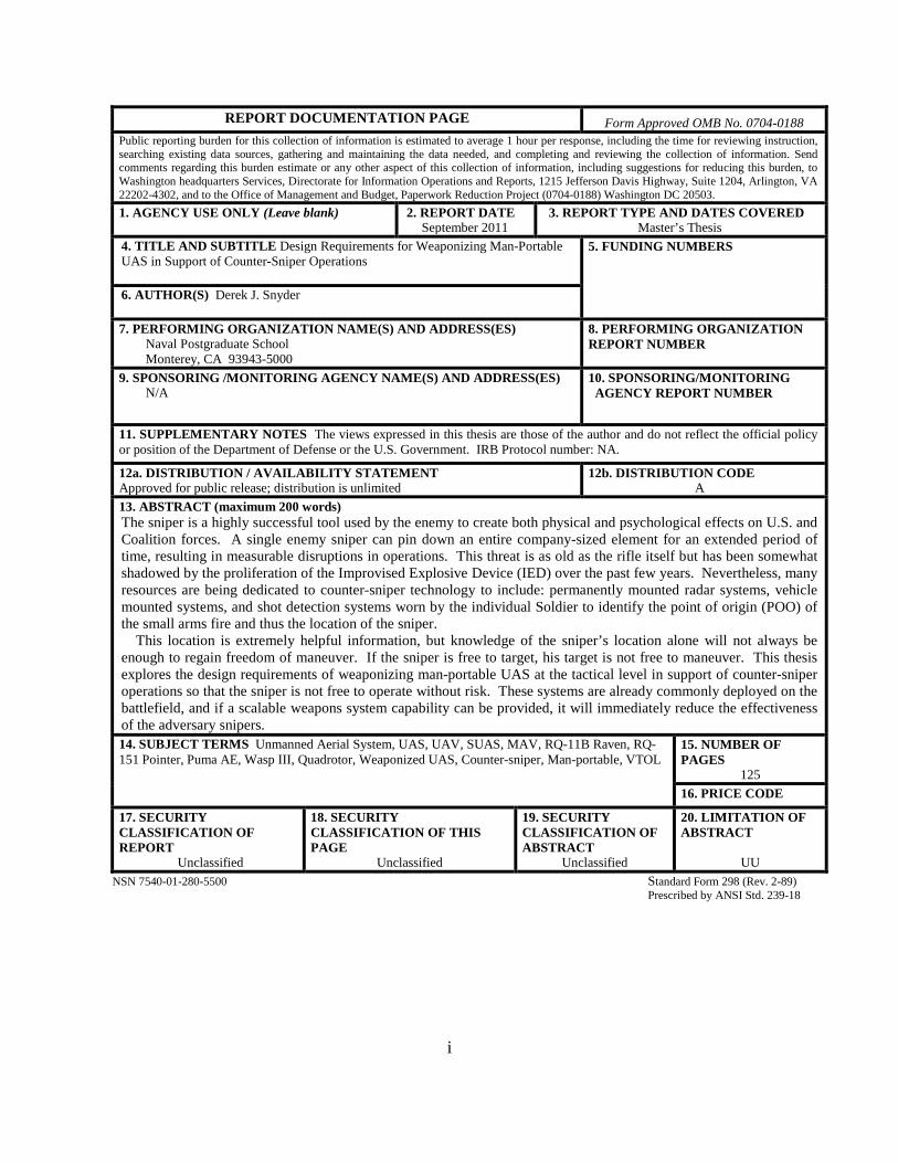
13. ABSTRACT (maximum 200 words) The sniper is a highly successful tool used by the enemy to create both physical and psychological effects on U.S. and Coalition forces. A single enemy sniper can pin down an entire company-sized element for an extended period of time, resulting in measurable disruptions in operations. This threat is as old as the rifle itself but has been somewhat shadowed by the proliferation of the Improvised Explosive Device (IED) over the past few years. Nevertheless, many resources are being dedicated to counter-sniper technology to include: permanently mounted radar systems, vehicle mounted systems, and shot detection systems worn by the individual Soldier to identify the point of origin (POO) of the small arms fire and thus the location of the sniper. This location is extremely helpful information, but knowledge of the sniper’s location alone will not always be enough to regain freedom of maneuver. If the sniper is free to target, his target is not free to maneuver. This thesis explores the design requirements of weaponizing man-portable UAS at the tactical level in support of counter-sniper operations so that the sniper is not free to operate without risk. These systems are already commonly deployed on the battlefield, and if a scalable weapons system capability can be provided, it will immediately reduce the effectiveness of the adversary snipers. 14. SUBJECT TERMS Unmanned Aerial System, UAS, UAV, SUAS, MAV, RQ-11B Raven, RQ-151 Pointer, Puma AE, Wasp III, Quadrotor, Weaponized UAS, Counter-sniper, Man-portable, VTOL
15. NUMBER OF PAGES
125 16. PRICE CODE
17. SECURITY CLASSIFICATION OF REPORT
Unclassified
18. SECURITY CLASSIFICATION OF THIS PAGE
Unclassified
19. SECURITY CLASSIFICATION OF ABSTRACT
Unclassified
20. LIMITATION OF ABSTRACT
UU NSN 7540-01-280-5500 Standard Form 298 (Rev. 2-89) Prescribed by ANSI Std. 239-18

ii
THIS PAGE INTENTIONALLY LEFT BLANK

iii
Approved for public release; distribution is unlimited
DESIGN REQUIREMENTS FOR WEAPONIZING MAN-PORTABLE UAS IN SUPPORT OF COUNTER-SNIPER OPERATIONS
Derek J. Snyder Major, United States Marine Corps
B.S., The Citadel, 2000
Submitted in partial fulfillment of the requirements for the degree of
MASTER OF SCIENCE IN INFORMATION WARFARE SYSTEMS ENGINEERING
from the
NAVAL POSTGRADUATE SCHOOL September 2011
Author: Derek J. Snyder
Approved by: Raymond R. Buettner, PhD Thesis Co-Advisor
Kevin D. Jones, PhD Thesis Co-Advisor
Dan C. Boger, PhD Chair, Department of Information Sciences

iv
THIS PAGE INTENTIONALLY LEFT BLANK

v
ABSTRACT
The sniper is a highly successful tool used by the enemy to create both physical and
psychological effects on U.S. and Coalition forces. A single enemy sniper can pin down
an entire company-sized element for an extended period of time, resulting in measurable
disruptions in operations. This threat is as old as the rifle itself but has been somewhat
shadowed by the proliferation of the Improvised Explosive Device (IED) over the past
few years. Nevertheless, many resources are being dedicated to counter-sniper
technology to include: permanently mounted radar systems, vehicle mounted systems,
and shot detection systems worn by the individual Soldier to identify the point of origin
(POO) of the small arms fire and thus the location of the sniper.
This location is extremely helpful information, but knowledge of the sniper’s
location alone will not always be enough to regain freedom of maneuver. If the sniper is
free to target, his target is not free to maneuver. This thesis explores the design
requirements of weaponizing man-portable UAS at the tactical level in support of
counter-sniper operations so that the sniper is not free to operate without risk. These
systems are already commonly deployed on the battlefield, and if a scalable weapons
system capability can be provided, it will immediately reduce the effectiveness of the
adversary snipers.

vi
THIS PAGE INTENTIONALLY LEFT BLANK
vii
TABLE OF CONTENTS
I. INTRODUCTION........................................................................................................1 A. THE PROBLEM ..............................................................................................1 B. OBJECTIVES ..................................................................................................4 C. THESIS STRUCTURE ...................................................................................5
II. PRESENT MILITARY UAS APPLICATIONS .......................................................7 A. UAS CATEGORIES ........................................................................................9 B. UAS MISSIONS .............................................................................................14 C. MAN-PORTABLE UAS ................................................................................16
1. FIXED WING SUAS .........................................................................17 a. RQ-11B Raven.........................................................................18 b. PUMA AE ................................................................................21 c. WASP III .................................................................................23
2. VERTICAL TAKEOFF-LANDING SUAS .....................................24 a. YRQ-16A..................................................................................25
D. INCREASING DEMAND FOR MAN-PORTABLE UAS .........................27 1. Increased Situational Awareness and Increased Standoff .............28 2. Increased Precision Targeting and Precision Lethality .................28 3. Decreased Response Time .................................................................29
III. THE SNIPER PROBLEM ........................................................................................31 A. ENEMY SNIPER PROBLEM IN OIF/OEF ...............................................31 B. CURRENT SNIPER DETECTION SYSTEMS .........................................33
1. Boomerang Vehicle Mounted Gunshot Detection System .............34 2. Individual Gunshot Detection System ..............................................35 3. Gunslinger Package for Advanced Convoy Security
(GunPACS) .........................................................................................36 C. CURRENT TACTICAL AND THEATER LEVEL UAS COUNTER-
SNIPER TECHNOLOGY .............................................................................37 1. Mini Weapons.....................................................................................38 2. Lethal Miniature Aerial Munitions Systems (LMAM) ..................39
IV. WEAPONIZED MAN-PORTABLE UAS DESIGN REQUIREMENTS .............43 A. INTRODUCTION..........................................................................................43 B. A SYSTEMS ENGINEERING APPROACH TO IDENTIFYING
REQUIREMENTS .........................................................................................43 1. The Systems Engineering Process ....................................................43
a. Systems Requirements Identification .....................................47 b. Determining Tasks ..................................................................49 c. Functional Analysis ................................................................50 d. System Design .........................................................................52
C. TNT/CBE 11-2 EXPERIMENTS MAC DILL AFB AUX FIELD (AVON PARK AIR FORCE RANGE) RQ-11B RAVEN ..........................55

viii
1. Quantitative/Qualitative Results ......................................................58 2. RQ-11 B Experiment Summary .......................................................62
D. PELICAN QUADROTOR EXPERIMENT CAMP ROBERTS, CA .......63 1. Quantitative/Qualitative Results for Pelican ...................................66 2. Pelican Quadrotor Experiment Summary.......................................69
E. TNT/CBE 11-3 EXPERIMENTS CAMP ROBERTS, CA RQM-151 POINTER AND GAUI 330X QUADROTOR .............................................69 1. Quantitative/Qualitative Results for Pointer...................................70 2. Quantitative/Qualitative Results for Quadrotor .............................77 3. CBE/TNT 11-3 Weaponized Pointer and Quadrotor
Experiment Summary .......................................................................83 F. SYSTEM DESIGN REQUIREMENTS .......................................................84
1. Navigation ...........................................................................................85 2. The Air Vehicle ..................................................................................87 3. Launch and Recovery ........................................................................88 4. Control Station ...................................................................................88 5. Communications ................................................................................89 6. Interfaces ............................................................................................89 7. Payload ................................................................................................89
a. The EO/IR Camera .................................................................89 b. The Weapon.............................................................................91
8. Support Equipment and Maintenance .............................................92 9. Transportation ...................................................................................92
V. CONCLUSIONS AND RECOMMENDATIONS ...................................................93 A. SUMMARY AND CONCLUSION ..............................................................93
LIST OF REFERENCES ......................................................................................................97
INITIAL DISTRIBUTION LIST .......................................................................................103
ix
LIST OF FIGURES
Figure 1. U.S. Army UAS effects on risk/time based on level of echelon (From U.S. Army unmanned aircraft systems roadmap 2010–2035, 2010) .........................3
Figure 2. Man-portable UAS used in support of counter-sniper operations .....................4 Figure 3. Joint UAS categories (From U.S. unmanned systems roadmap 2007–2032,
2010) ................................................................................................................10 Figure 4. USMC Tier I/II/III UAS categories (From Isherwood & Garrison, 2008) .....11 Figure 5. DoD U.S. flight hours (From hearing on budget request on unmanned
aerial vehicles, 2007) .......................................................................................14 Figure 6. Raven, Puma, and Wasp shared GCS (From Hoff, 2009) ...............................18 Figure 7. RQ-11 Raven B with GCS and handheld video monitor (From Defense
Industry Daily, 2011) .......................................................................................20 Figure 8. Puma AE launch from small craft (From Hoff, 2009) .....................................22 Figure 9. Wasp III micro air vehicle (From U.S. AFSOC, 2011) ...................................24 Figure 10. Fukashima number 4 reactor damage obtained by the RQ-16 T-Hawk
MAV (From Curry, 2011)................................................................................26 Figure 11. Honeywell RQ-16 T-Hawk diagram (From Frank, 2009) ...............................27 Figure 12. USMC UAS pre-mission flow (From FMFM 3-22-1, 1993) ..........................30 Figure 13. Individual gunshot detection system (From Hornyak, 2011) ..........................36 Figure 14. GunPACS weapon over watch system for use on the MTVR (From Clark,
2010) ................................................................................................................37 Figure 15. Spike missile and fire control system (From NAWCWD, 2010) ....................39 Figure 16. AeroVironment Switchblade LMAM (From Defense-Update, 2010) .............40 Figure 17. Systems engineering process (From Defense Acquisition University,
2001) ................................................................................................................45 Figure 18. Functional configurations in system of systems (SOS) configuration (From
Blanchard, 2008) ..............................................................................................46 Figure 19. Development spiral (From Mawn & Tokumaru, 2006) ...................................48 Figure 20. Raven B design products from the conceptual design phase through
system operations use and life cycle support ...................................................49 Figure 21. IDEF0 template to identify resource requirements (From Blanchard, 2008) ..51 Figure 22. Major steps of system design and development (From Blanchard, 2008) .......53 Figure 23. The cost impact due to changes (From Blanchard, 2008) ...............................54 Figure 24. Before and after weights in grams of the modified nonlethal paintball gun
used as UAS proof of concept payload in the experiments ............................57 Figure 25. RQ-11B experiment at Mac Dill Aux Field, Avon Park, FL ...........................57 Figure 26. Non-lethal weaponized Raven B during CBE 11-2, Avon Park, FL ...............59 Figure 27. Non-lethal weaponized Raven B during CBE 11-2, Avon Park, FL ...............59 Figure 28. Target used in the nonlethal weaponized RQ-11B experiment during CBE
11-2, Avon Park, FL ........................................................................................60 Figure 29. First person RQ-11B pilot and trigger operator view on RQ-11B GCS
flying the nonlethal weaponized RQ-11B firing at man-sized target during CBE 11-2, Avon Park, FL................................................................................61
x
Figure 30. Illustration of various movements of a quadrotor (From Domingues, 2009) ..64 Figure 31. Pelican Quadrotor experiment Camp Roberts McMillan Airfield, CA ...........65 Figure 32. Ascending Technologies AscTec autopilot interface ......................................67 Figure 33. Modified Ascending Technologies Pelican quadrotor with wireless camera
and nonlethal paintball gun ..............................................................................67 Figure 34. Pelican quadrotor armed with nonlethal paintball gun hovering in front of
the target...........................................................................................................68 Figure 35. Modified nonlethal multi-shot paintball gun weights ......................................72 Figure 36. Nonlethal paintball gun payload aboard the RQ-151 Pointer ..........................74 Figure 37. Nonlethal weaponized RQ-151 Pointer used during TNT/CBE 11-3
counter-sniper scenario ....................................................................................74 Figure 38. Counter-sniper target scenario using RQ-151 Pointer and man-sized mock-
up during TNT/CBE 11-3 ................................................................................75 Figure 39. First person RQ-151 Pointer pilot and trigger operator view on RQ-11B
GCS flying the nonlethal weaponized RQ-11B firing at man-sized target during TNT/CBE 11-3. The interlaced video composite shows the paint ball at two times during the shot ......................................................................75
Figure 40. Nonlethal weaponized Pointer counter-sniper scenario impact measurements during TNT/CBE 11-3 .............................................................76
Figure 41. Weaponized quadrotor system weights ...........................................................79 Figure 42. Counter-sniper target scenario using a quadrotor against a man-sized
target during TNT/CBE 11-3 ...........................................................................80 Figure 43. First person quadrotor pilot and trigger operator view while firing at man-
sized target during TNT/CBE 11-3 ..................................................................82 Figure 44. Nonlethal weaponized quadrotor counter-sniper scenario paintball impact
locations ...........................................................................................................83 Figure 45. UAV system—functional structure (From Austin, 2010) ................................85 Figure 46. C/A and P(Y) code frequency differences (From Abidin, 2002) .....................86 Figure 47. Processing gain comparison between the C/A and P(Y) code (From Hui
Hu, 2009) .........................................................................................................87 Figure 48. UAS camera look-down angle and vertical FOV ............................................90
xi
LIST OF TABLES
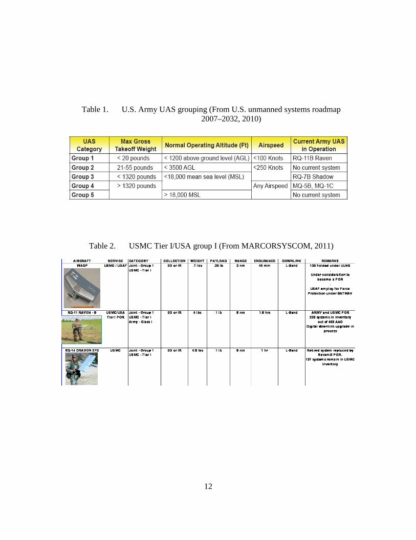
Table 1. U.S. Army UAS grouping (From U.S. unmanned systems roadmap 2007–2032, 2010) ......................................................................................................12
Table 2. USMC Tier I/USA group I (From MARCORSYSCOM, 2011) .....................12 Table 3. USMC Tier II & III, USA Group III & IV, and joint group 4 (From
MARCORSYSCOM, 2011) ............................................................................13 Table 4. COCOM and Military Department UAS needs prioritized by aircraft class
(From U.S. unmanned systems roadmap 2007–2032, 2007) ...........................16 Table 5. RQ-11 B Raven specifications (From Aerovironment, Inc., 2010a) ...............21 Table 6. Puma AE specifications (From AeroVironment Inc., 2010b) .........................22 Table 7. WASP III specifications (From AeroVironment Inc., 2011c) .........................24 Table 8. YRQ-16A T-Hawk specifications (From Flightglobal, 2011) .........................27 Table 9. Ascending Technologies Pelican Quadrotor Specifications (From AscTec,
2011) ................................................................................................................66 Table 10. RQ-151 Pointer specifications (From FMI 3-04.155, 2006) ...........................71 Table 11. GAUI 330X Quadrotor specifications (From TSH Gaui, 2011)......................78 Table 12. FlyCamOne3 camera specifications (From FlyCamOne, 2011)......................79

xii
THIS PAGE INTENTIONALLY LEFT BLANK
xiii
LIST OF ACRONYMS AND ABBREVIATIONS
AO Area of Operations
AF Air Force
C2 Command and Control
CG Center of Gravity
COIN Counter-Insurgency Operations
COTS Commercial Off-the-Shelf
COP Common Operational Picture
DARPA Defense Advanced Research Project Agency DAU Defense Acquisition University
DHS Department of Homeland Security
DoD Department of Defense
EO Electrical Optical
EOD Explosive Ordnance Disposal
FOB Forward Operating Base
FOV Field of View
FPV First Person Video
GPS Global Positioning System
GCS Ground Control Station
GTOW Gross Takeoff Weight
HMWWV High Mobility Multipurpose Wheeled Vehicle
HUD Heads-Up Display
HVT High Value Target
IED Improvised Explosive Device
IR Infrared
ISR Intelligence, Surveillance, and Reconnaissance
JMETL Joint Mission Essential Task List
JTF Joint Task Force
LOS Line-of-Sight
MAGTF Marine Air Ground Task Force
MAV Micro Air Vehicle
xiv
MCTL Marine Corps Task List
MET Mission Essential Task
METL Mission Essential Task List
MEU Marine Expeditionary Unit
MOS Military Occupational Specialty
MSL Mean Sea Level
MTVR Medium Tactical Vehicle Replacement
NPS Naval Postgraduate School
NRT Near Real-Time
NTA Navy Tactical Tasks
OEF Operation Enduring Freedom
OIF Operation Iraqi Freedom
OODA Observe Orient Decide Act
ONR Office of Naval Research
PID Positive Identification PO Payload Operator
POO Point of Origin
R&D Research and Development
RADAR Radio Detection and Ranging
RF Radio Frequency
ROE Rules of Engagement
RSTA Reconnaissance, Surveillance, and Target Acquisition
RVT Remote Video Terminal
SA Situational Awareness
SIGINT Signal Intelligence
SOF Special Operations Forces
SOP Standard Operating Procedures
SU Situational Understanding
SUAV Small Unmanned Aerial Vehicle
TIC Troops In Contact
TNT Tactical Network Topology
TST Time Sensitive Targets

xv
TTLI Tracking, Tagging, Locating and Identifying
TTP Tactics, Techniques, and Procedures
UAV Unmanned Aerial Vehicle
UAS Unmanned Aerial Systems
UJTL Universal Joint Task List
UNS Urgent Needs Statement
UNTL Universal Naval Task List
U.S. United States
UT Unit Trainer
USN United States Navy
USMC United States Marine Corps
USA United States Army
USSOCOM United States Special Operations Command
VO Vehicle Operator
WIA Wounded In Action
WX Weather

xvi
THIS PAGE INTENTIONALLY LEFT BLANK
xvii
EXECUTIVE SUMMARY
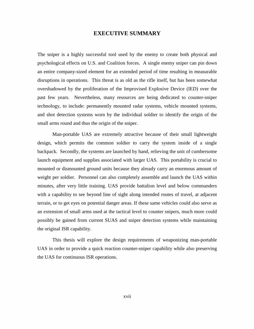
The sniper is a highly successful tool used by the enemy to create both physical and
psychological effects on U.S. and Coalition forces. A single enemy sniper can pin down
an entire company-sized element for an extended period of time resulting in measurable
disruptions in operations. This threat is as old as the rifle itself, but has been somewhat
overshadowed by the proliferation of the Improvised Explosive Device (IED) over the
past few years. Nevertheless, many resources are being dedicated to counter-sniper
technology, to include: permanently mounted radar systems, vehicle mounted systems,
and shot detection systems worn by the individual soldier to identify the origin of the
small arms round and thus the origin of the sniper.
Man-portable UAS are extremely attractive because of their small lightweight
design, which permits the common soldier to carry the system inside of a single
backpack. Secondly, the systems are launched by hand, relieving the unit of cumbersome
launch equipment and supplies associated with larger UAS. This portability is crucial to
mounted or dismounted ground units because they already carry an enormous amount of
weight per soldier. Personnel can also completely assemble and launch the UAS within
minutes, after very little training. UAS provide battalion level and below commanders
with a capability to see beyond line of sight along intended routes of travel, at adjacent
terrain, or to get eyes on potential danger areas. If these same vehicles could also serve as
an extension of small arms used at the tactical level to counter snipers, much more could
possibly be gained from current SUAS and sniper detection systems while maintaining
the original ISR capability.
This thesis will explore the design requirements of weaponizing man-portable
UAS in order to provide a quick reaction counter-sniper capability while also preserving
the UAS for continuous ISR operations.

xviii
THIS PAGE INTENTIONALLY LEFT BLANK

xix
ACKNOWLEDGMENTS
I would like to express my sincere appreciation to my thesis advisors for not only
steering me through the completion of this research but more importantly for dedicating
their lives to the advancement of U.S. and Coalition operational capabilities.
Thanks to Dr. Raymond Buettner for allowing me to take on this project and for
introducing me to one of the Naval Postgraduate School’s greatest experimentation
venues—the USSOCOM sponsored Tactical Network Testbed (TNT). Much
appreciation is also owed to Dr. Kevin Jones, who consistently used his vast knowledge
of unmanned systems to quickly turn ideas into payloads.
Special thanks to the NPS Center for Autonomous Vehicle Research for their
unlimited support and guidance. Very special thanks to Aurelio Monarrez, whose
professionalism and motivation have set the example for the center’s dedication to
advancing unmanned systems technology.
Thanks also to my Information Warfare Systems Engineering classmates of 2011,
for selflessly dedicating their precious time to ensuring we all “got it” on countless
occasions over the past two years. Without your help, I would have undoubtedly
floundered.
Most importantly, I would like to thank my wife, Melissa, and our daughters,
Hannah and Sidney, for sharing in this experience and by providing their unwavering
support throughout our time in Monterey.

xx
THIS PAGE INTENTIONALLY LEFT BLANK

1
I. INTRODUCTION
A. THE PROBLEM
Since the invention of the modern rifle, snipers have been successfully employed
in combat. Highly trained snipers are invaluable reconnaissance assets to a commander
and can be used for countless other missions to include counter-sniper operations. The
benefits gained through employing this capability accrue to our enemies as well,
particularly following the initial highly kinetic invasion phase of operations. Throughout
Operations Iraqi Freedom (OIF) and Enduring Freedom (OEF), enemy snipers have been
especially effective against U.S. and Coalition forces because of the nature of counter-
insurgency (COIN) operations (Jervis, 2006). U.S. forces of company-sized elements or
smaller routinely patrol vast distances over harsh terrain within their areas of
responsibility (AOR) via dismounted patrols on foot or mounted in convoys where they
are constantly exposed to sniper attacks. COIN operations require constant interaction
with the local populace in order to be successful, further increasing the risk of attack. In
this asymmetric environment, the enemy will employ any measure to prevent the success
of COIN operations and one of their most effective weapons is the time tested sniper
(Golnar, 2010).
Snipers can position themselves within crowded urban areas where they are
difficult to identify, and where risk of collateral damage prevents U.S. forces from using
large munitions to eliminate them. Snipers can use extreme terrain to create natural
obstacles and land barriers between themselves and U.S. forces to prevent counterattacks.
Once engaged by a sniper, conventional U.S. forces face the extremely challenging
problem of determining the sniper’s location, confirming the location, maneuvering to the
location, and finally eliminating the sniper. Consequently, an effective sniper can pin
down an entire company-sized element for an extended period of time, resulting in
measurable disruptions to operations. This disruption only escalates with added sniper-
induced casualties.
2
Until recent technological breakthroughs, nothing differentiated the strategy of a
Korean War era platoon commander pinned down by a sniper from that of a modern one
fighting in mountainous Afghanistan. Both commanders would have had to put someone
at risk by maneuvering into a position from which the sniper’s location could be
identified, while possibly attempting to draw fire from the sniper so that the sniper
reveals his location. Ultimately, someone would be required to maneuver in order to
eliminate the sniper or force him to reposition. Today, however, forces are equipped with
counter-sniper systems that immediately aid in determining the sniper’s location. This
saves valuable time in maintaining momentum, aids in quickly formulating a plan, and
reduces the chaos and confusion for a commander in the aftermath of a sniper attack. A
sniper’s suspected position is vital information to the commander; however, it does not
mitigate the risk to human life in maneuvering to counter the sniper.
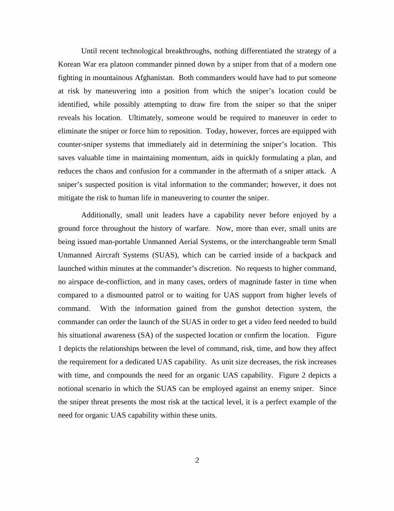
Additionally, small unit leaders have a capability never before enjoyed by a
ground force throughout the history of warfare. Now, more than ever, small units are
being issued man-portable Unmanned Aerial Systems, or the interchangeable term Small
Unmanned Aircraft Systems (SUAS), which can be carried inside of a backpack and
launched within minutes at the commander’s discretion. No requests to higher command,
no airspace de-confliction, and in many cases, orders of magnitude faster in time when
compared to a dismounted patrol or to waiting for UAS support from higher levels of
command. With the information gained from the gunshot detection system, the
commander can order the launch of the SUAS in order to get a video feed needed to build
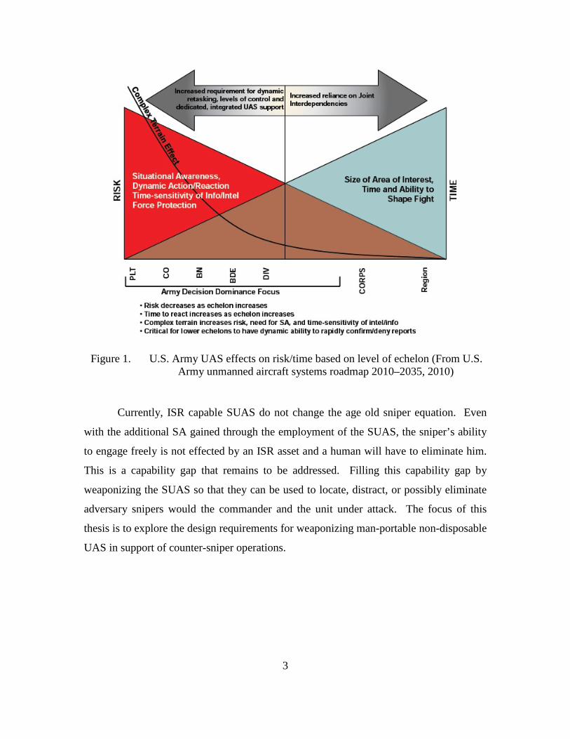
his situational awareness (SA) of the suspected location or confirm the location. Figure
1 depicts the relationships between the level of command, risk, time, and how they affect
the requirement for a dedicated UAS capability. As unit size decreases, the risk increases
with time, and compounds the need for an organic UAS capability. Figure 2 depicts a
notional scenario in which the SUAS can be employed against an enemy sniper. Since
the sniper threat presents the most risk at the tactical level, it is a perfect example of the
need for organic UAS capability within these units.
3
Figure 1. U.S. Army UAS effects on risk/time based on level of echelon (From U.S. Army unmanned aircraft systems roadmap 2010–2035, 2010)
Currently, ISR capable SUAS do not change the age old sniper equation. Even
with the additional SA gained through the employment of the SUAS, the sniper’s ability
to engage freely is not effected by an ISR asset and a human will have to eliminate him.
This is a capability gap that remains to be addressed. Filling this capability gap by
weaponizing the SUAS so that they can be used to locate, distract, or possibly eliminate
adversary snipers would the commander and the unit under attack. The focus of this
thesis is to explore the design requirements for weaponizing man-portable non-disposable
UAS in support of counter-sniper operations.

4
Figure 2. Man-portable UAS used in support of counter-sniper operations
B. OBJECTIVES
The goal of this research is to explore the design requirements of weaponizing
man-portable UAS through capabilities-based field experimentation. Conceptual design
requirements will be leveraged from existing man-portable UAS, specifically, by
weaponizing a RQ-11B Raven, RQ-151 Pointer, and COTS quadrotor UAS with a proof-
of-concept nonlethal paintball gun in order to explore the feasibility of taking an existing
system and modifying it with a small arms capability. Specific issues to be addressed
include:
1. The trigger mechanism controllability, functionality, operator workload, and
integration with the rest of the communications system. Much effort has gone into
optimizing how a soldier interfaces with current UAS and this could be affected by
adding the additional tasks of also targeting and firing on a sniper.
2. The armed UAS flight characteristics at various profiles. Size, Weight, and
Power (SWAP) considerations are inherent to all aircraft design. UAS will suffer
decreased endurance by adding any additional weight or parasitic drag. SUAS have a
5
fixed amount of available power. Any change to the design will affect the performance
of the aircraft. This work examined at the tradeoffs associated with the additional weight
and drag associated with adding a small arms payload, how the flight characteristics and
endurance are affected and if these tradeoffs are worth the additional counter-sniper
capability. SUAS are designed to work at low altitudes, which enable them to get close
enough to a sniper while being small enough to make them extremely hard to shoot
down. Because of their small size and low available power, the weight of the small arms
payload will be the limiting factor in the overall design of the system. This weight
restriction will require exploration into current technology in weapons miniaturization,
manufacturing materials, and advancements beyond the traditional heavy mechanical
small arms solutions being used by the operating forces.
3. The majority of the color electro-optical (EO) cameras on SUAS are hard
mounted into the payload in a fixed-focus and fixed-position optimal for persistent ISR
missions. This effort examined how the current cameras can be used in a counter-sniper
mission, how the camera can be bore-sighted and aimed and overall camera functionality
and compatibility with the rest of the communications systems.
4. Next, the research will explore how much weaponizing the SUAS will affect
the required launch time. One of the greatest attributes of the SUAS is their simplicity
and short time to launch. Potentially, the impact of the added workload of mounting and
arming a small arms payload is of concern. Safety concerns associated with launch and
recovery were also explored.
5. Finally, this work explored the overall effect gained by weaponizing the
SUAS, more specifically, how accurate was the nonlethal payload delivery with respect
to target location.
C. THESIS STRUCTURE
In Chapter II, the current UAS situation within the DoD, current man-portable
UAS variants, and the increasing demand for UAS is discussed. In Chapter III, the focus
is on the enemy with respect to DoD combat operations and how the potential for man-
portable UAS capabilities at the tactical level to counter this threat.

6
Chapter IV explores the design requirements for weaponizing man-portable UAS
in support of counter-sniper operations through field experiments, which utilized both
fixed wing and rotary wing man-portable UAS armed with a proof of concept nonlethal
paintball gun. Chapter IV also discusses the potential lethal small arms solutions to
weaponize man-portable UAS.
In Chapter V, the research findings are discussed and recommendations for future
work are suggested.
7
II. PRESENT MILITARY UAS APPLICATIONS
Since the execution of OIF and OEF, the United States has invested heavily in
unmanned systems, specifically UAS. The UAS revolution has impacted most aspects of
air warfare to include increased intelligence and situational awareness, increased lethality
and precision, and decreased collateral damage (Hearing on Budget Request on
Unmanned Aerial Vehicles [UAV] and Intelligence, Surveillance, and Reconnaissance
[ISR] Capabilities, 2007). However, the largest return on investment and the driving
factor for UAS proliferations has been the reduced risk gained by having a relatively
inexpensive robot replace a human in performing the dull, dirty, and dangerous missions.
Dull missions executed by manned aircraft such as ISR can span more than 20
hours per mission. Manned ISR missions require a pilot to fly for 11 hours or more,
which can be extremely taxing physiologically. “Military and civilian applications such
as extended surveillance can be a dulling experience for aircrew, with many hours spent
on watch without relief, and can lead to a loss of concentration and therefore a loss of
mission effectiveness” (Austin, 2010, p. 5). Taking mission effectiveness and safety
aside, we have hit a point in ISR extended flight time missions where the human has
become the limiting factor in keeping a platform airborne for the maximum possible time.
The overwhelming success of the Predator drone in Iraq and Afghanistan has been
recognized by other organizations that also face manpower shortages. Since September
11, 2001, the United States increased its ISR missions at unprecedented rates. The
Predator fleet was increased by 350% in order to support the demand (House of
Representatives, Air and Land Forces Subcommittee, 2007). “The little drone has
quickly become perhaps the busiest U.S. asset in the air. From June 2005 to June 2006,
Predators carried out 2,073 missions, flew 33,833 hours, surveyed 18,490 targets, and
participated in 242 separate raids. Even with this massive effort, there is demand for
more” (Singer, 2011).
The demand for UAS is also increasing within the Central Command area of
responsibility. The U.S. Department of Homeland Security (DHS) is responsible for

8
patrolling more than 3,000 miles of U.S. border—an infinitely large ISR mission that
falls into the “dull” category. The DHS has three Predators flying along the Mexican
border, two along the Canadian border, and one over the Caribbean. “In the last five
years, predators have helped net 40,000 pounds of drugs and nab 7,000 illegal
immigrants, according to Homeland Security” (Orr, 2010).
Dirty missions may require aircrews to fly into Nuclear, Biological, or Chemical
(NBC) contaminated air space where specialized suits would have to be worn and both
the aircraft and aircrews would have to undergo extensive detoxification procedures upon
completion of the mission (Austin, 2010). UAS can penetrate beyond the limits of
aircrew NBC gear or aircrew physiological limitations. In the event of NBC gear failure,
both the aircrew and aircraft could be lost. This is not the case with a robot (UAS Vision,
2011). Machines do not suffer from the same g-force limitations, they do not need to be
augmented with oxygen systems or pressurized cabins, neither do they succumb to crew
coordination mistakes (Austin, 2010).
On March 11, 2011, an earthquake off the coast of Japan triggered a tsunami that
hit the Japanese coast devastating everything in the path, including a nuclear power plant
which housed four nuclear reactors (Dorell, 2011). The damaged nuclear reactors were
leaking dangerous levels of radiation into the ocean and atmosphere for miles
surrounding the plant. This made the area extremely difficult to access by humans or
even land-based robots. “A camera was mounted on a remote-controlled helicopter
(Honeywell T-Hawk) to get pictures of the damaged reactors from above in hopes of
getting a better look at the damaged housings of the No. 1, 3 and 4 reactors” (Smith,
2011). Historically, a human would have accepted the risk of life-threatening radiation
exposure in order to assess the reactors, but robots can penetrate dirty areas with
sophisticated high-definition cameras (UAS Vision, 2011). Imagery gained from UAS in
situations like this is crucial for planners to accurately assess the situation and put the
least amount of human lives at risk during repair and containment missions.
A very important reason for investing in UAS is to reduce the risk to human life
associated with dangerous missions. “Lower downside risk and higher confidence in
mission success are two strong motivators for continued expansion of unmanned systems
9
across a broad spectrum of warfighting and peacetime missions” (Under Secretary of
Defense, 2007, p. 33). Technology is, however, a resource shared by all and does not
only favor the United States. The same benefits of technology enjoyed by the United
States are now beginning to spread throughout the globe and will also benefit the
militaries of enemy states. As enemy technology improves in anti-air defense systems,
the risk to the United States of sending highly trained aircrews aboard multimillion dollar
aircraft against them will begin to outweigh the intended effects. “Adversaries ashore are
obtaining new guided rockets, artillery, mortars, and missiles (G-RAMM). Together,
these developments undermine the lead in guided weapons warfare that the United States
and its allies have enjoyed since the end of Operation DESERT STORM, and they
threaten to eliminate the virtual operational sanctuary our Navy has enjoyed at sea since
World War II” (Work, 2010). UAS are generally smaller than their manned counterparts,
which results in a smaller radar cross section and therefore a reduced chance of being
eliminated by enemy air defenses. Additionally, UAS are much cheaper to build than
manned aircraft. The loss of a UAS does not also result in the loss of highly trained
aircrew (Austin, 2010).
Humans require complicated flight control systems and tailored physiological
support systems in order to fly. Human-machine interface points within the aircraft are
some of the most vital design requirements of a manned aircraft. By removing humans
and the associated cabin space, controls, and components needed by human pilots,
engineers can design UAS much more efficiently to accomplish the same missions and
carry the same payloads. “The UAV equipped with surveillance sensors can be typically
only 3–4% of the weight, require only 2.5% of the engine power (and 3% fuel
consumption) and 25% of the size (wing/rotor span) of the light aircraft” (Austin, 2010,
p. 7). Cost savings has been a driving factor for the shift from manned aircraft to UAS.
A. UAS CATEGORIES
Current UAS categorization within DoD can differ greatly depending on the level
of command, the service component, and within the joint services. While this is not
important when addressing the capabilities of the individual platforms, it becomes very

10
important when identifying what units are supported by what vehicles. Figure 3 depicts
the categories as defined by the Joint U.S. Unmanned Systems Roadmap 2007–2032
where UAS are categorized by takeoff weight and strike capability by listing them as
small, Tactical, Theater, or Combat. This differs from both the U.S. Marine Corps,
depicted in Figure 4, and the U.S. Army categories depicted in Table 1. The difference in
how UAS are categorized does introduce some possibilities for confusion. For instance,
the Joint definition for a small UAS is one that weighs less than 55 pounds. While not a
significant amount of weight, 55 pounds would not be considered man-portable for
tactical operations. Tables 2 and 3 list the current UAS within DoD and the categories to
which they belong. In order to understand why there are so many different vehicles, it
would be beneficial to understand the missions that the systems are required to perform.
Small—Gross takeoff weight (GTOW) less than 55 pounds. Tactical—GTOW between 55 and 1320 pounds. Theater—GTOW greater than 1320 pounds. Combat—An aircraft designed from inception as a strike platform with internal bomb bays or external weapons pylons, a high level of survivability, and GTOW greater than 1320 pounds. An example is the Navy Unmanned Combat Air System.
Figure 3. Joint UAS categories (From U.S. unmanned systems roadmap 2007–2032, 2010)
The USMC categorizes UAS by the level of command at which the UAS will be
flown in support of and based on the capabilities of the system (Figure 4). This is divided
into groups, or Tiers, based on operating altitude and range: Tier I UAS are flown at the
Battalion level and below; Tier II UAS are flown in support of the Battalion, Regiment,
Division, and Marine Expeditionary Unit (MEU) commanders. Tier III UAS are flown in
support of Joint operations, specifically a Joint Task Force (JTF), or Marine Air Ground
Task Force (MAGTF) commander.

11
Figure 4. USMC Tier I/II/III UAS categories (From Isherwood & Garrison, 2008)
The U.S. Army categorizes UAS into five groups, based on takeoff weight,
operating altitude and airspeed. The Army:
Currently employs UAS across all echelons as dedicated or organic support to tactical, operational, and strategic operations. The typical Army UAS echelons are:
Battalion-level and lower: close-range (less than 25 kilometers), short duration (one to two hours) missions that operate below the coordinating altitude and are thoroughly integrated with ground forces as an organic asset supporting tactical operations.
Brigade-level: medium-range (less than 125 kilometers), medium-duration (five to 10 hours) missions that integrate with ground forces and other aviation assets.
Division-level and higher: extended range (200 kilometers or more), long duration (16 hours or more), missions in direct support (DS), or general support (GS) and at the tactical or operational level. (UAS Roadmap, 2010)
12
Table 1. U.S. Army UAS grouping (From U.S. unmanned systems roadmap 2007–2032, 2010)
Table 2. USMC Tier I/USA group I (From MARCORSYSCOM, 2011)

13
Table 3. USMC Tier II & III, USA Group III & IV, and joint group 4 (From MARCORSYSCOM, 2011)
14
B. UAS MISSIONS
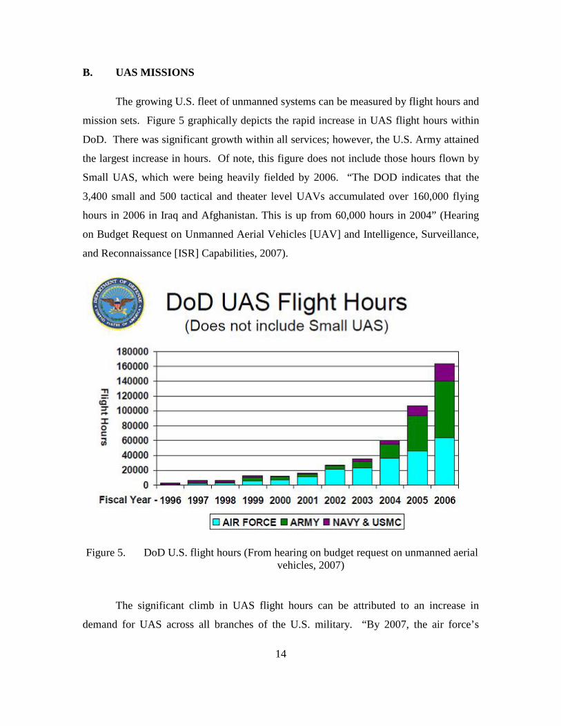
The growing U.S. fleet of unmanned systems can be measured by flight hours and
mission sets. Figure 5 graphically depicts the rapid increase in UAS flight hours within
DoD. There was significant growth within all services; however, the U.S. Army attained
the largest increase in hours. Of note, this figure does not include those hours flown by
Small UAS, which were being heavily fielded by 2006. “The DOD indicates that the
3,400 small and 500 tactical and theater level UAVs accumulated over 160,000 flying
hours in 2006 in Iraq and Afghanistan. This is up from 60,000 hours in 2004” (Hearing
on Budget Request on Unmanned Aerial Vehicles [UAV] and Intelligence, Surveillance,
and Reconnaissance [ISR] Capabilities, 2007).
Figure 5. DoD U.S. flight hours (From hearing on budget request on unmanned aerial vehicles, 2007)
The significant climb in UAS flight hours can be attributed to an increase in
demand for UAS across all branches of the U.S. military. “By 2007, the air force’s
15
drones were logging more than 250,000 flight hours a year. The next year air force
drones would log another 400,000 hours. The entire fleet of more than 700 Army drones
in Iraq logged 300,000 flight hours in 2007” (Singer, 2009, p. 226). What was once a
strategic level capability is now also organic to company sized elements and these tactical
level commanders are depending on small UAS as their eyes and ears while fighting in
extremely unforgiving terrain. The U.S. Army alone reached 1,000,000 total UAS flight
hours in May 2010, a significant achievement for a branch that serves as the nation’s
ground force:
It took 13 years to fly the first 100,000 hours and less than a year to fly the next 100,000. In the past two years alone the Army has flown more than 500,000 hours. As of April 14, the Army had flown 1,002,731 unmanned aerial system hours, nearly 90 percent of that time in Iraq and Afghanistan. (Carden, 2010)
This rapid accumulation of flight hours is not only the result of the rising demand for
UAS at all levels of command but, more importantly, the extensive utilization of the these
systems over increasingly diverse mission types.
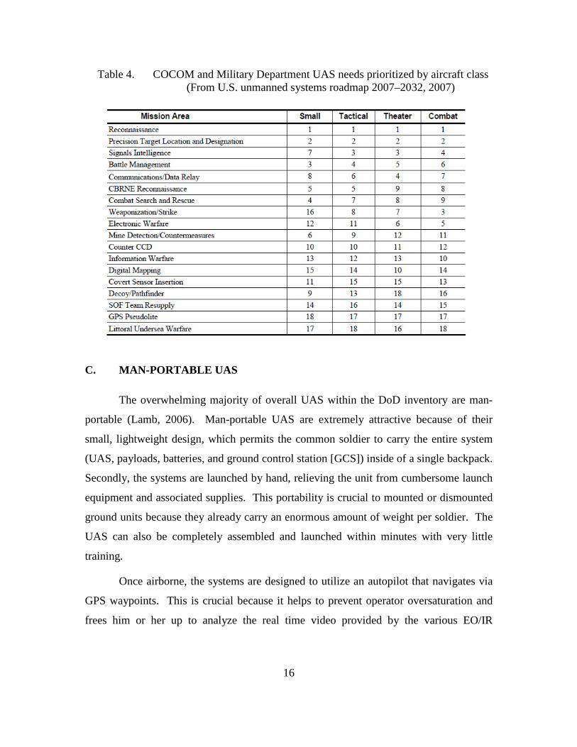
The U.S. Unmanned System Roadmap has identified 18 specific UAS mission
areas. Table 4 depicts each mission area listed from the highest priority (1) to lowest
priority (18). Reconnaissance and Precision Target Location and Designation remain the
top priorities at the Joint level. For the U.S. Army and U.S. Marine Corps, ISR also takes
the top priorities in UAS mission areas. This comes as little surprise as UAS have always
been used in support of these missions. However, the lower priority missions are on the
extreme end of the UAS employment spectrum. These low-priority irregular mission
types are examples of how the DoD is integrating UAS into a variety of missions far from
the roots of reconnaissance. They also exemplify how the DoD is striving to gain more
from these systems than just ISR; this thesis focuses on how man-portable UAS could be
used for multiple missions.
16
Table 4. COCOM and Military Department UAS needs prioritized by aircraft class (From U.S. unmanned systems roadmap 2007–2032, 2007)
C. MAN-PORTABLE UAS
The overwhelming majority of overall UAS within the DoD inventory are man-
portable (Lamb, 2006). Man-portable UAS are extremely attractive because of their
small, lightweight design, which permits the common soldier to carry the entire system
(UAS, payloads, batteries, and ground control station [GCS]) inside of a single backpack.
Secondly, the systems are launched by hand, relieving the unit from cumbersome launch
equipment and associated supplies. This portability is crucial to mounted or dismounted
ground units because they already carry an enormous amount of weight per soldier. The
UAS can also be completely assembled and launched within minutes with very little
training.
Once airborne, the systems are designed to utilize an autopilot that navigates via
GPS waypoints. This is crucial because it helps to prevent operator oversaturation and
frees him or her up to analyze the real time video provided by the various EO/IR
17
payloads available with the system. Once the operator desires to terminate the flight, the
UAS can be directed to a terminal waypoint where it will enter an auto-land mode so that
is can be collected and quickly disassembled.
These UAS are primarily used for close range ISR missions within a few
kilometers of the operating unit. They provide battalion level and below commanders
with a capability to see beyond line of site along intended routes of travel, at adjacent
terrain, or to get eyes on potential danger areas such as rooftops or higher surrounding
terrain. All tasks of the pre-UAS era that would have required the added time and risk
associated with employing a slowly moving dismounted element with a radio, to gain
intelligence that is relatively old when compared to the dynamics and tempo of current
operations at the tactical level. The EO/IR cameras capture real-time video with enough
resolution for the commander to determine the overall situation to include enough detail
to see a person holding a weapon. The advantage of real-time intelligence against an
enemy who does not enjoy the same, creates an information advantage for that
commander.
1. FIXED WING SUAS
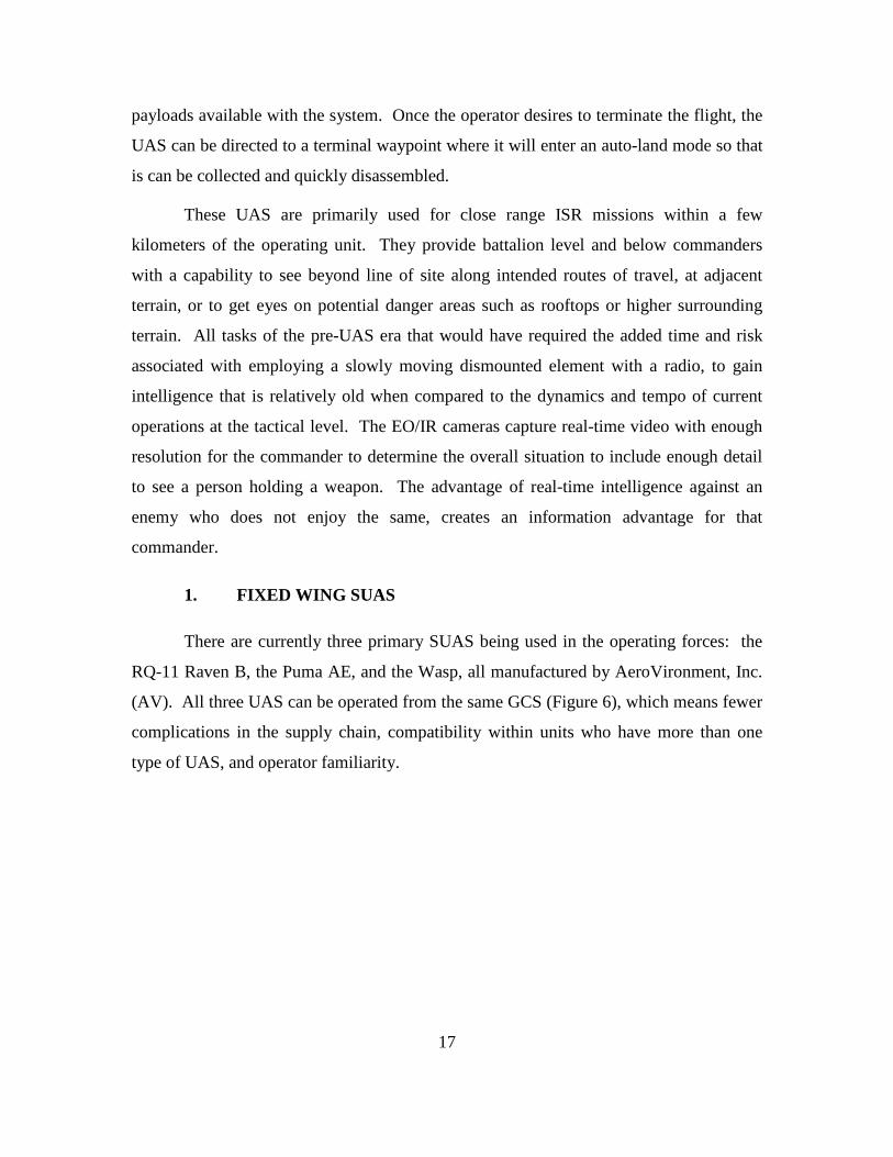
There are currently three primary SUAS being used in the operating forces: the
RQ-11 Raven B, the Puma AE, and the Wasp, all manufactured by AeroVironment, Inc.
(AV). All three UAS can be operated from the same GCS (Figure 6), which means fewer
complications in the supply chain, compatibility within units who have more than one
type of UAS, and operator familiarity.
18
Figure 6. Raven, Puma, and Wasp shared GCS (From Hoff, 2009)
a. RQ-11B Raven
When it comes to man-portable UAS, the RQ-11 Raven has been a
venerable workhorse at 500 ft and below. Weighing in at only 4.2 pounds (see Table 2),
the current Raven B is highly portable and quickly deployable. Its durable carbon fiber
construction has been proven to endure the rigors of combat. The standard system comes
with three airframes, three nose-cone payloads, two ground control stations, and all
associated batteries and spare parts. The batteries power a single electric engine for up to
90 minutes of flight. These batteries also provide power for a color high-resolution
down-looking, or side-looking camera or infrared camera, for day and night operations.
Once the Raven is hand launched (Figure 7), it can be flown autonomously or manually
out to ranges of 10 km and up to altitudes of 500 ft AGL. Once a target has been located,
the Raven can orbit overhead with very little engine noise and keep the target within
view.
The Raven was designed and produced by AeroVironment (AV) Inc., and
when it comes to man-portable UAS, AV has dominated the competition. The
company’s success has not been a trivial accomplishment or one that took place

19
overnight. Since the mid-1980s, AV has been developing man-portable UAS for use at
the tactical level starting with the FQM-151 Pointer. “Originally developed for the U.S.
Marine Corps in 1986, Pointer is a man-portable system that provides the capability for
troops to see over the next hill with a hand-launched UAV” (AeroVironment, 2011d).
Further development in man-portable UAS resulted in a contract between
AeroVironment and the USMC for the RQ-14 Dragon Eye/Swift:
The UAV was operationally used for the first time during OIF in 2003 for reconnaissance and battle damage assessment. In November 2003, the Dragon Eye production prime contract was awarded to AeroVironment, and the USMC’s procurement plans called for 467 Dragon Eye systems with 3 UAVs each. In early 2007, the official designation RQ-14A was finally allocated to the Dragon Eye. (Parsh, 2007a)
The Dragon Eye was later replaced by AeroVironment’s Raven line of man-portable
UAS.
The Raven A was quickly replaced by the Raven B, which now serves as
the primary man-portable fixed wing UAS within DoD. The Raven B is the product of
years of research and development and evaluation in support of combat operations in
both OIF and OEF. The Raven B is the most advanced SUAS within DoD and is used by
the USA, USMC, AF, and U.S. Special Operations Command (SOCOM). Additionally,
AV has delivered the Raven to numerous coalition partners resulting in the delivery of
over 9,000 airframes to both military and civilian organizations worldwide.
Dependability and ease of use are key features of the Raven. Operators
must complete a “10-day, 80-hour course of academic and operational instruction before
they’re qualified on the RQ-11B” (O’Connor, 2007). Many operators get qualified to fly
the Raven as a collateral duty, meaning they have another Primary Military Occupational
Skill (PMOS). The Army manual for Unmanned Aircraft System Operations states the
job description for a Raven B operator as “the Raven UAS Vehicle Operator (VO) (MOS
NONDESCRIPT) must be tactically, as well as technically proficient” (USA UAS
Operations, 2006). The UAS operator is responsible for mission programming into the
GCU, remote operating of the UAS, and handling recovery of the UAS. This system

20
provides a significant savings in time and costs to obtain valuable intelligence from the
air when compared to the costs of training human aviators over a two-year period. “The
Raven with its toy-like appearance may be fun to operate but training to minimize the
loss of Soldiers and damage to equipment is serious business” (Richardson, 2011). The
Raven’s lightweight fuselage is constructed of Kevlar, which can withstand nose dive
crashes into pavement, allowing the UAS to enter a deep stall and crash as its primary
way to land.
Finally, the Raven’s greatest capability is simply that it works. Many
systems introduced into the military result in added time and work for operators,
unacceptable life cycles, or high repair rates, which result in the operators bringing the
gear, but never using it. Ravens are being used heavily and are being incorporated into
doctrine while the demand for them continues to grow. “This shift in demand is driven
by platoons that are responsible for covering large swaths of land with few soldiers”
(Defense Daily, 2010).
Figure 7. RQ-11 Raven B with GCS and handheld video monitor (From Defense Industry Daily, 2011)
21
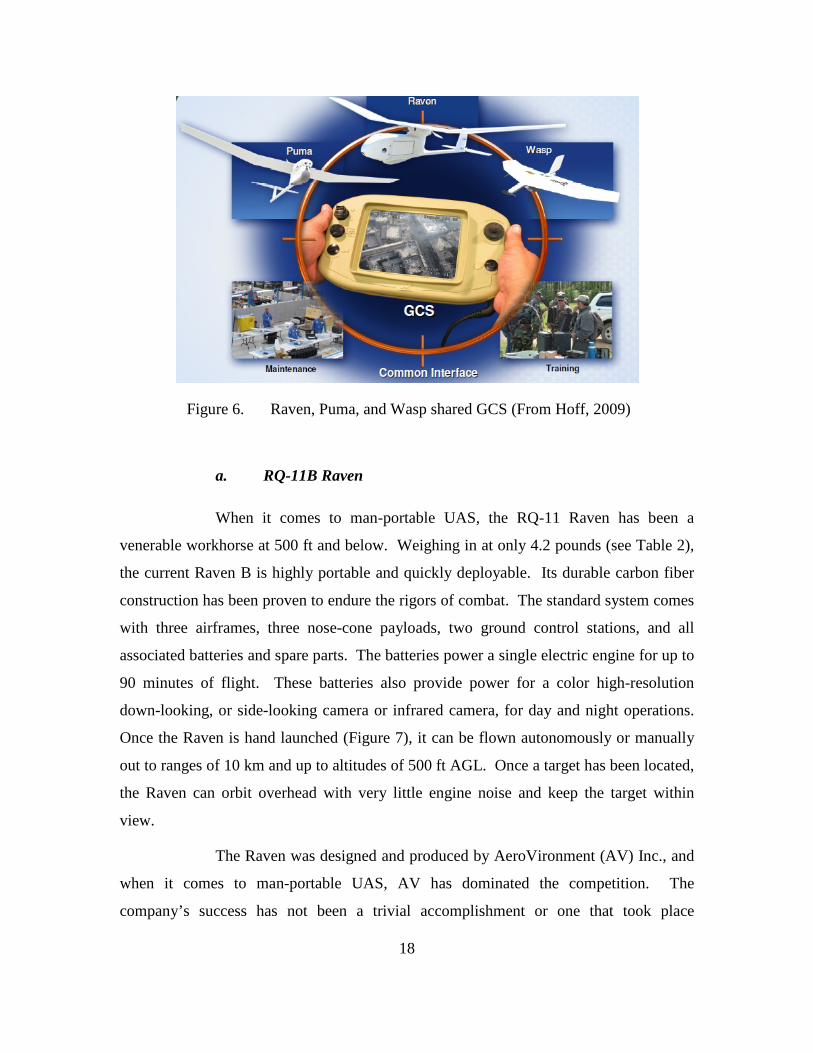
Table 5. RQ-11 B Raven specifications (From Aerovironment, Inc., 2010a)
Design Feature Specification Standard Payloads Dual Forward and Side-Look EO Camera Nose, Electronic
Pan-tilt-zoom with Stabilization, Forward and Side-Look IR Camera Nose (6.5 oz payloads).
Range 10 km Endurance 60–90 minutes Speed 32–81 km/h, 17–44 kt Operating Altitude 100–500 ft (30–152 m) AGL 14,000 ft MSL max launch
altitude Wing Span 4.5 ft (1.4 m) Length 3.0 ft (0.9 m) Weight 4.2 lbs (1.9 kg) Ground Control Station Lightweight, Modular Components, Waterproof Soft case,
Optional FalconView Moving Map and Mission Planning Laptop
Launch and Recovery Hand-Launched, Deep Stall Landing
b. PUMA AE
The Puma All Environment (AE) is an All Environment Capability
Solution (AECS) to the fixed wing man-portable UAS family. Originally contracted by
U.S. SOCOM in 2008, the Puma is currently operated only by special operations units.
The Puma is larger when compared to the Raven, but can still be hand launched. Its
ability to fly in adverse weather conditions make it favorable for a broader array of ISR
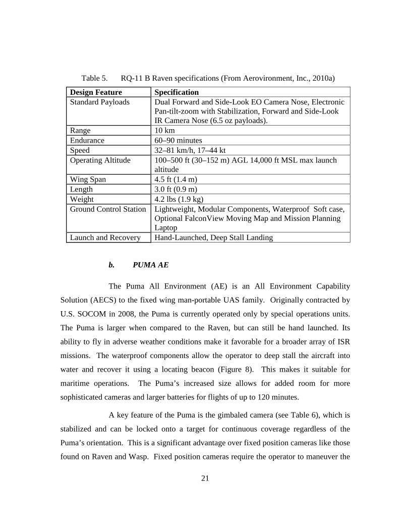
missions. The waterproof components allow the operator to deep stall the aircraft into
water and recover it using a locating beacon (Figure 8). This makes it suitable for
maritime operations. The Puma’s increased size allows for added room for more
sophisticated cameras and larger batteries for flights of up to 120 minutes.
A key feature of the Puma is the gimbaled camera (see Table 6), which is
stabilized and can be locked onto a target for continuous coverage regardless of the
Puma’s orientation. This is a significant advantage over fixed position cameras like those
found on Raven and Wasp. Fixed position cameras require the operator to maneuver the
22
entire aircraft in order to aim the camera at the desired location, which can require
valuable time in an already time limited operation.
Figure 8. Puma AE launch from small craft (From Hoff, 2009)
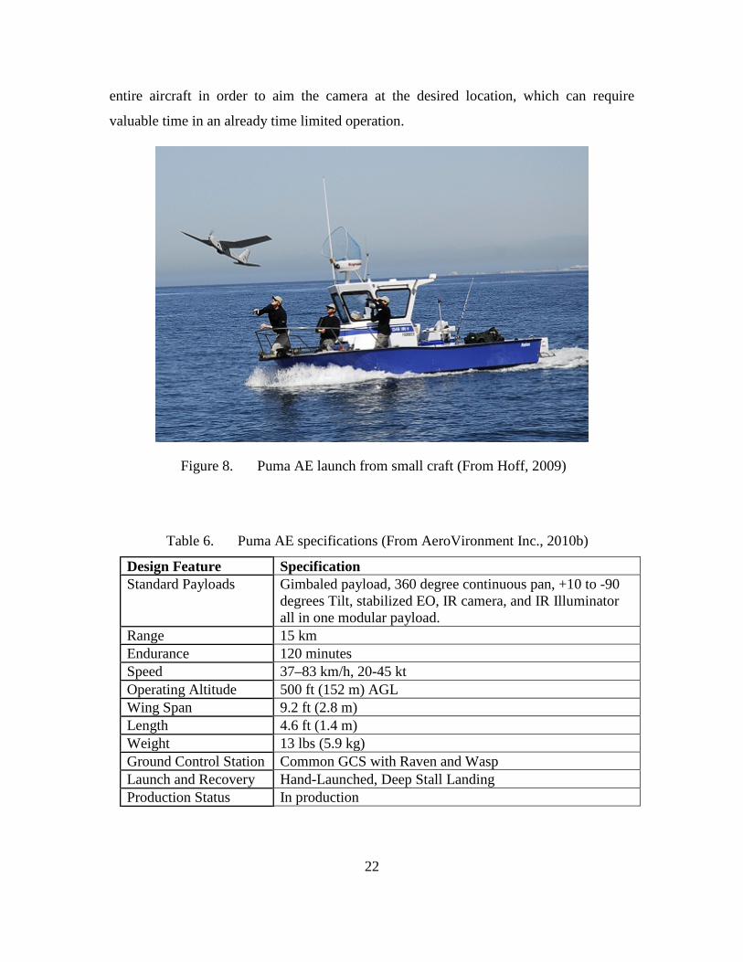
Table 6. Puma AE specifications (From AeroVironment Inc., 2010b)
Design Feature Specification Standard Payloads Gimbaled payload, 360 degree continuous pan, +10 to -90
degrees Tilt, stabilized EO, IR camera, and IR Illuminator all in one modular payload.
Range 15 km Endurance 120 minutes Speed 37–83 km/h, 20-45 kt Operating Altitude 500 ft (152 m) AGL Wing Span 9.2 ft (2.8 m) Length 4.6 ft (1.4 m) Weight 13 lbs (5.9 kg) Ground Control Station Common GCS with Raven and Wasp Launch and Recovery Hand-Launched, Deep Stall Landing Production Status In production
23
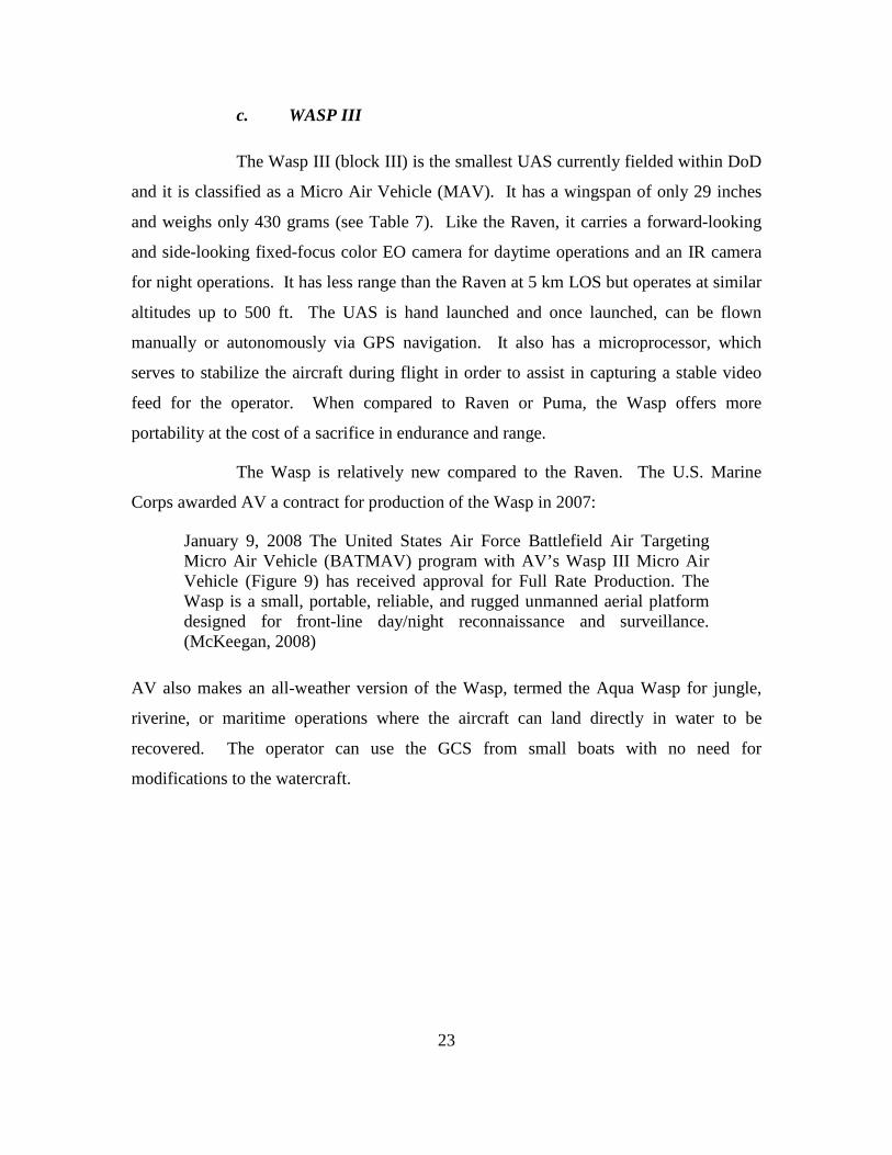
c. WASP III
The Wasp III (block III) is the smallest UAS currently fielded within DoD
and it is classified as a Micro Air Vehicle (MAV). It has a wingspan of only 29 inches
and weighs only 430 grams (see Table 7). Like the Raven, it carries a forward-looking
and side-looking fixed-focus color EO camera for daytime operations and an IR camera
for night operations. It has less range than the Raven at 5 km LOS but operates at similar
altitudes up to 500 ft. The UAS is hand launched and once launched, can be flown
manually or autonomously via GPS navigation. It also has a microprocessor, which
serves to stabilize the aircraft during flight in order to assist in capturing a stable video
feed for the operator. When compared to Raven or Puma, the Wasp offers more
portability at the cost of a sacrifice in endurance and range.
The Wasp is relatively new compared to the Raven. The U.S. Marine
Corps awarded AV a contract for production of the Wasp in 2007:
January 9, 2008 The United States Air Force Battlefield Air Targeting Micro Air Vehicle (BATMAV) program with AV’s Wasp III Micro Air Vehicle (Figure 9) has received approval for Full Rate Production. The Wasp is a small, portable, reliable, and rugged unmanned aerial platform designed for front-line day/night reconnaissance and surveillance. (McKeegan, 2008)
AV also makes an all-weather version of the Wasp, termed the Aqua Wasp for jungle,
riverine, or maritime operations where the aircraft can land directly in water to be
recovered. The operator can use the GCS from small boats with no need for
modifications to the watercraft.
24
Figure 9. Wasp III micro air vehicle (From U.S. AFSOC, 2011)
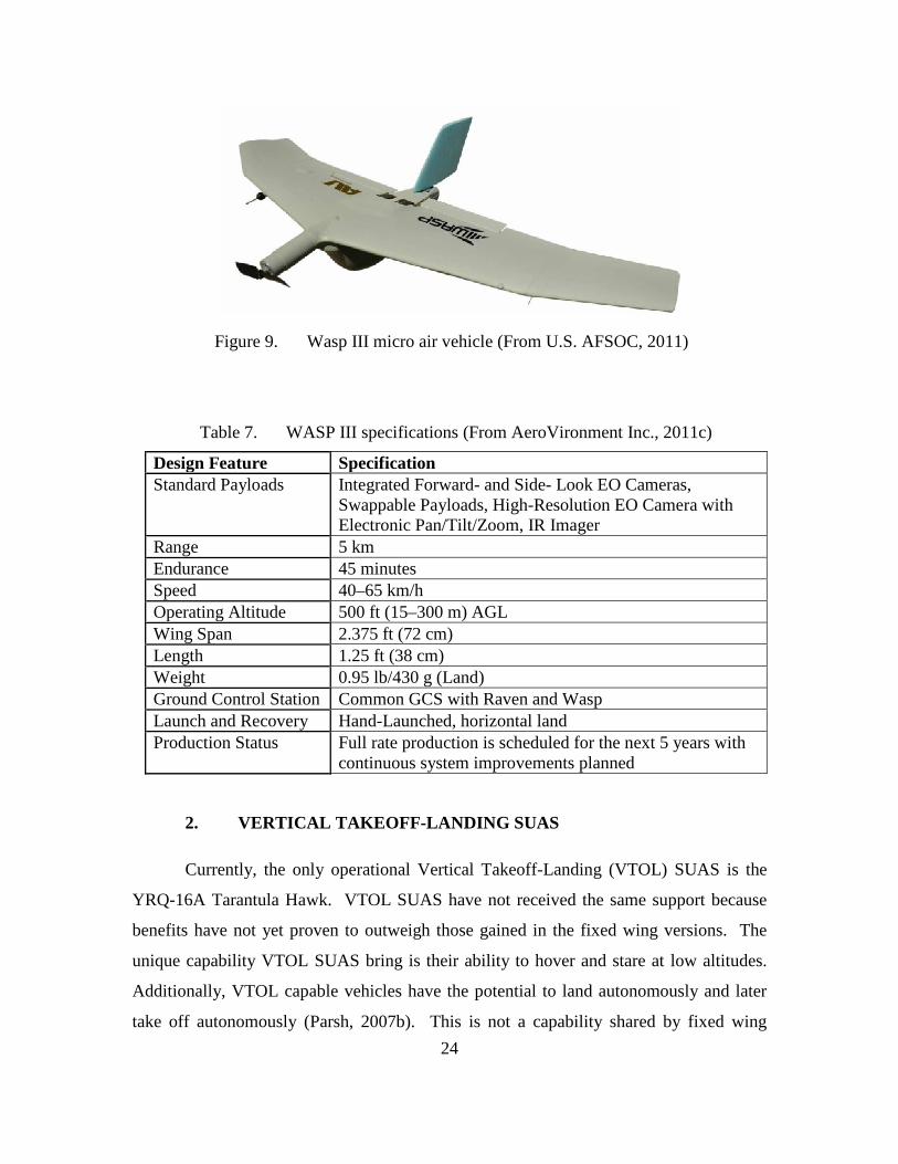
Table 7. WASP III specifications (From AeroVironment Inc., 2011c)
Design Feature Specification Standard Payloads Integrated Forward- and Side- Look EO Cameras,
Swappable Payloads, High-Resolution EO Camera with Electronic Pan/Tilt/Zoom, IR Imager
Range 5 km Endurance 45 minutes Speed 40–65 km/h Operating Altitude 500 ft (15–300 m) AGL Wing Span 2.375 ft (72 cm) Length 1.25 ft (38 cm) Weight 0.95 lb/430 g (Land) Ground Control Station Common GCS with Raven and Wasp Launch and Recovery Hand-Launched, horizontal land Production Status Full rate production is scheduled for the next 5 years with
continuous system improvements planned
2. VERTICAL TAKEOFF-LANDING SUAS
Currently, the only operational Vertical Takeoff-Landing (VTOL) SUAS is the
YRQ-16A Tarantula Hawk. VTOL SUAS have not received the same support because
benefits have not yet proven to outweigh those gained in the fixed wing versions. The
unique capability VTOL SUAS bring is their ability to hover and stare at low altitudes.
Additionally, VTOL capable vehicles have the potential to land autonomously and later
take off autonomously (Parsh, 2007b). This is not a capability shared by fixed wing
25
UAS, which require human assistance to take off after landing. Aerodynamically, VTOL
flight is extremely resource taxing and power intensive, which reduces the overall
endurance of the vehicle and total time the operator has over a target. However, recently
some missions have been identified that make VTOL SUAS like the T-Hawk the right
tool for the job.
a. YRQ-16A
The YRQ-16 Tarantula Hawk uses a gasoline powered engine to produce
thrust, which is then ducted through an intricate system of blades to maneuver the UAS.
Much like the Raven, it uses an autopilot system that allows operators to simply point and
click waypoints into software and the vehicle will takeoff, fly the route, and land
autonomously. The USN was responsible for the RQ-16 initial production when in 2008
it purchased 372 for future use in support of combat operations. The T-Hawk is currently
being used by Explosive Ordnance Disposal Teams (EOD) in Afghanistan to search
congested urban areas for IEDs:
Unlike some other models of UAVs, the T-Hawk can take off and land vertically, which makes it useful in areas with obstructions like buildings or mountains where other UAVs cannot operate. The ability to land vertically also allows the operators to land the T-Hawk within 15 feet of their location, limiting their exposure while on patrol. (Mortimer, 2010)
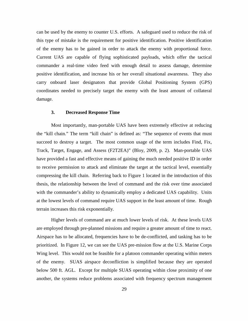
As seen in Table 8, the T-Hawk’s weight puts it at the upper limits of the man-portable
category (Figure 11). The T-Hawk’s gasoline engine produces much more noise than a
battery operated SUAS. This makes it impractical for covert ISR at low altitudes as the
ducted fan and engine noise would alert anyone in the vicinity of its presence, but the
vehicle has been very useful in situations where the operators do not care if the enemy
has knowledge of the robot’s presence near the target. An example of this would be a
roadside bomb which has been discovered and requires EOD to evaluate and disarm it.
There are very few elements of surprise associated with a stopped U.S. convoy
attempting to disarm an IED.
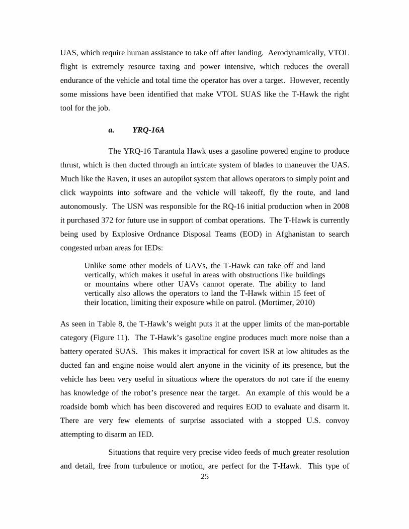
Situations that require very precise video feeds of much greater resolution
and detail, free from turbulence or motion, are perfect for the T-Hawk. This type of
26
video is difficult to capture with a constantly moving fixed wing SUAS. Roadside bombs
are usually much smaller than a man-sized target and therefore require the UAS to reduce
the standoff distance in order to get a better look at the target. Additionally, if the target
is located in a tight area such as an alley, it would only be visible within the FOV of a
fixed wing UAS for a few seconds at most—not feasible for this mission. The recent
Fukashima, Japan nuclear reactor disaster was initially unreachable by ground robots, and
humans would have been exposed to a lifetime of radiation exposure within 5 minutes if
sent in to assess the damage. The T-Hawk was able to fly into the facility—often flying
between damaged structures and hovering within a few feet of walls in order to obtain the
extremely detailed real-time video (RTV) from various aspects needed by responders (see
Figure 10).
Figure 10. Fukashima number 4 reactor damage obtained by the RQ-16 T-Hawk MAV (From Curry, 2011)
VTOL technology is continually improving especially in the field of
battery powered vehicle such as quadrotors. As mission endurance increases in VTOL
design, this type of vehicle will become more attractive for missions in urban
environments. The future warfighter may not need something that “sees over the next
hill” but instead something that sees over the next building, alley, or into the next
window. Although none are operational at the moment, quadrotor potential is explored in
this thesis.
27
Table 8. YRQ-16A T-Hawk specifications (From Flightglobal, 2011)
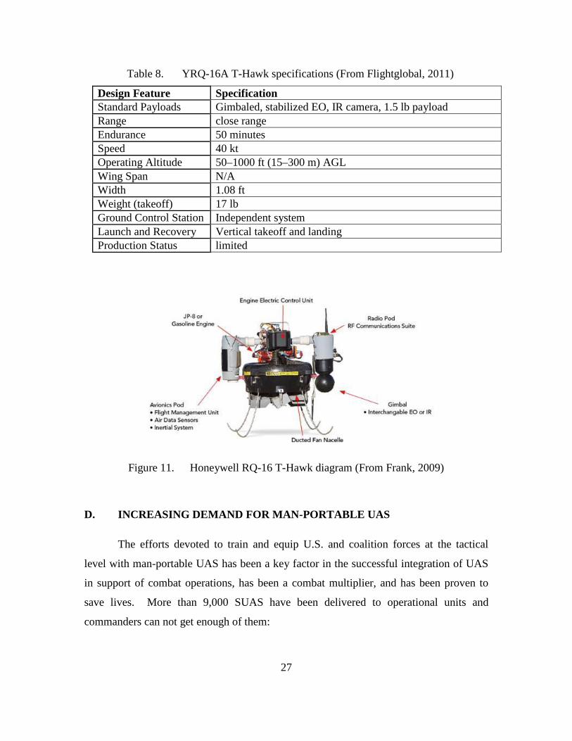
Design Feature Specification Standard Payloads Gimbaled, stabilized EO, IR camera, 1.5 lb payload Range close range Endurance 50 minutes Speed 40 kt Operating Altitude 50–1000 ft (15–300 m) AGL Wing Span N/A Width 1.08 ft Weight (takeoff) 17 lb Ground Control Station Independent system Launch and Recovery Vertical takeoff and landing Production Status limited
Figure 11. Honeywell RQ-16 T-Hawk diagram (From Frank, 2009)
D. INCREASING DEMAND FOR MAN-PORTABLE UAS
The efforts devoted to train and equip U.S. and coalition forces at the tactical
level with man-portable UAS has been a key factor in the successful integration of UAS
in support of combat operations, has been a combat multiplier, and has been proven to
save lives. More than 9,000 SUAS have been delivered to operational units and
commanders can not get enough of them:

28
The Army provides every brigade combat team with 15 Raven systems, each of which includes three of the hand-launched, remote-controlled aircraft. There are nine BCTs, mostly in southern Afghanistan, that want to increase their number of systems to 35 each. (Beidel, 2011)
Not too long ago, the only way to perform battle damage assessment (BDA) or
reconnaissance, surveillance, and target acquisition (RSTA) from the air was to have a
fully trained Aerial Observer or to use national assets such as satellites. Human
observers had to be flown aboard a manned light aircraft such as an OV-10 Bronco and
the only way to conduct ISR was to either divert priceless satellite time or task manned
aircraft. All of which require thousands of hours of training and millions of dollars in
aircraft and equipment. The commanders at the tactical level had to request support and
were then prioritized depending on time and availability of ISR assets and in most
situations would have been lucky to be dedicated a sliver of the requested support. This
is still the case for those who are not lucky enough to have their own man-portable ISR
capability organic to the unit.
1. Increased Situational Awareness and Increased Standoff
Situational awareness (SA) can be defined as: “the perception of elements in the
environment within a volume of time and space, the comprehension of their meaning, and
the projection of their status in the near future” (Endsley, 1995, p. 37). Perception is
achieved through all available senses, or in the case of UAS, all available sensors. Given
that the SUAS available to the tactical commander is properly employed, the
commander’s SA has been extended out to the range of the UAS which extends the
volume of observed space in the same amount of time. The elements gained from the
UAS video feed would not be available to the commander without the UAS. This
dramatic increase in SA can be used to speed up a commander’s ability to observe, orient,
decide, and act (OODA) on the updated information.
2. Increased Precision Targeting and Precision Lethality
Collateral damage at the tactical level can easily result in adverse strategic effects.
Mistakes on the part of U.S. troops that result in the death or injury of innocent civilians
29
can be used by the enemy to counter U.S. efforts. A safeguard used to reduce the risk of
this type of mistake is the requirement for positive identification. Positive identification
of the enemy has to be gained in order to attack the enemy with proportional force.
Current UAS are capable of flying sophisticated payloads, which offer the tactical
commander a real-time video feed with enough detail to assess damage, determine
positive identification, and increase his or her overall situational awareness. They also
carry onboard laser designators that provide Global Positioning System (GPS)
coordinates needed to precisely target the enemy with the least amount of collateral
damage.
3. Decreased Response Time
Most importantly, man-portable UAS have been extremely effective at reducing
the “kill chain.” The term “kill chain” is defined as: “The sequence of events that must
succeed to destroy a target. The most common usage of the term includes Find, Fix,
Track, Target, Engage, and Assess (F2T2EA)” (Bloy, 2009, p. 2). Man-portable UAS
have provided a fast and effective means of gaining the much needed positive ID in order
to receive permission to attack and eliminate the target at the tactical level, essentially
compressing the kill chain. Referring back to Figure 1 located in the introduction of this
thesis, the relationship between the level of command and the risk over time associated
with the commander’s ability to dynamically employ a dedicated UAS capability. Units
at the lowest levels of command require UAS support in the least amount of time. Rough
terrain increases this risk exponentially.
Higher levels of command are at much lower levels of risk. At these levels UAS
are employed through pre-planned missions and require a greater amount of time to react.
Airspace has to be allocated, frequencies have to be de-conflicted, and tasking has to be
prioritized. In Figure 12, we can see the UAS pre-mission flow at the U.S. Marine Corps
Wing level. This would not be feasible for a platoon commander operating within meters
of the enemy. SUAS airspace deconfliction is simplified because they are operated
below 500 ft. AGL. Except for multiple SUAS operating within close proximity of one
another, the systems reduce problems associated with frequency spectrum management
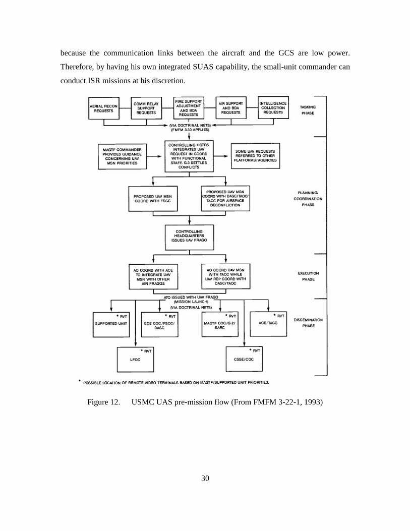
30
because the communication links between the aircraft and the GCS are low power.
Therefore, by having his own integrated SUAS capability, the small-unit commander can
conduct ISR missions at his discretion.
Figure 12. USMC UAS pre-mission flow (From FMFM 3-22-1, 1993)
31
III. THE SNIPER PROBLEM
A. ENEMY SNIPER PROBLEM IN OIF/OEF
The U.S. invasion of Iraq in the spring of 2003 was swift and efficient. Saddam
Hussein’s forces either surrendered or were neutralized and he was forced into hiding.
However, immediately following the completion of the major kinetic operations, a
combination of crumbling socio-economic conditions, disbanded Iraqi military and
former Ba’th party members all began to fuel organized hierarchical and decentralized
leadership for the various insurgent groups. In May 2003, the formation of a massive
insurgency began to challenge U.S. and Coalitions forces. There were two types of
fighters within the insurgent organizations, based on available manpower and skill levels,
combatant cells and specialized cells (Keegan, 2005).
Combatant components formed numerous cells, all of which consisted of anyone
who committed acts of violence against the U.S. and Coalition forces. Enemy snipers
could be found within any combatant cells, but the trained snipers were usually part of
the specialized cells that supported the combatant cell operations. “Specialized cells
(technical and bomb-making, logistics, suicide bomber support of facilitator,
reconnaissance and operational security) exist to support the combatant cells” (Hashin,
2006, p. 160) The IED and sniper threats of early OIF to U.S. forces quickly became the
catalyst for an episode that has resulted in the most advanced force protection systems in
the history of warfare. Wireless jammers were mass produced to protect U.S. convoys,
ground breaking vehicle hulk designs, acoustic shot detection systems, body armor, and
sensors beyond belief to someone just five years prior to inception—were all developed,
tested, and fielded in a matter of months. Still, the IED reigned over all other enemy
threats and as U.S. technology grew more effective at countering it, the enemy shifted
tactics and began to employ more sniper attacks. Today, the sniper problem persists in
OEF operations.
In February 2010, a NATO effort to infiltrate the southern Taliban stronghold of
Marjah, Afghanistan included participants from across the U.S. DoD spectrum, Coalition
32
forces, and Afghan forces. The ten-month battle was a key piece in the overall OEF
strategy to regain control of Afghanistan. The Taliban resistance was fierce and this time
the biggest threat to friendly forces was not the IED, it was the sniper:
Several of the engagements have escalated into fights that have filled days. And during the fighting, the Taliban has shown a side not often seen in nearly a decade of American military action in southern and eastern Afghanistan: the use of snipers, both working alone and integrated into guerrilla-style ambushes. (Chivers, 2010)
This battle, much like battles in Iraq, was painstakingly slow. The enemy knew
U.S. ROE and would use it against them by using noncombatants as shields and by
fighting within close proximity of family homes—forcing the U.S. forces to limit their
use of heavy machine guns or close air support in order to limit civilian casualties:
Comparing this with Iraq, I’m surprised with the accuracy. Capable and proficient … A team, two people, could conceivable [sic] suppress a size of three companies. Someone sticks their head up and you get a round which just misses or hits you will paralyze a unit, there’s probably nothing more lethal other than unmanned aerial stuff. (Golnar, 2010)
Optimal areas of attack for enemy snipers are very similar to where U.S. snipers
would be best employed. These areas include rooftops and windows in urban areas,
observed U.S. routes of travel and likely avenues of approach, dead space, as covering
fire for other forces, and anywhere else they can successfully engage while maintaining
an escape route. The typical range of an enemy sniper is between 300 and 600 meters.
Ranges in excess of 1000 meters are rare.
In the U.S. military lexicon there are three general categories of snipers: specially
trained sniper, trained marksman, and armed irregular (HQ USA Combined arms
operations in urban terrain, 2002). The specially trained sniper is the most dangerous and
most difficult to counter. They have in-depth training and are highly effective at hitting
targets at ranges out to 1,000 meters. They are usually regulars who wear a uniform and
have knowledge of their units overall concept of operations. The trained marksman can
be found in greater numbers. They are also specially trained and employ a rifle and
scope that enable him or her to reach ranges beyond normal small arms. They are not as
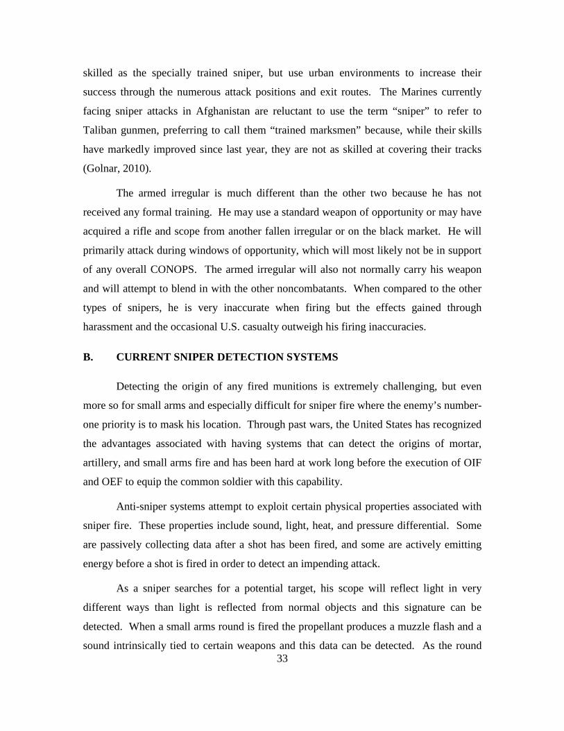
33
skilled as the specially trained sniper, but use urban environments to increase their
success through the numerous attack positions and exit routes. The Marines currently
facing sniper attacks in Afghanistan are reluctant to use the term “sniper” to refer to
Taliban gunmen, preferring to call them “trained marksmen” because, while their skills
have markedly improved since last year, they are not as skilled at covering their tracks
(Golnar, 2010).
The armed irregular is much different than the other two because he has not
received any formal training. He may use a standard weapon of opportunity or may have
acquired a rifle and scope from another fallen irregular or on the black market. He will
primarily attack during windows of opportunity, which will most likely not be in support
of any overall CONOPS. The armed irregular will also not normally carry his weapon
and will attempt to blend in with the other noncombatants. When compared to the other
types of snipers, he is very inaccurate when firing but the effects gained through
harassment and the occasional U.S. casualty outweigh his firing inaccuracies.
B. CURRENT SNIPER DETECTION SYSTEMS
Detecting the origin of any fired munitions is extremely challenging, but even
more so for small arms and especially difficult for sniper fire where the enemy’s number-
one priority is to mask his location. Through past wars, the United States has recognized
the advantages associated with having systems that can detect the origins of mortar,
artillery, and small arms fire and has been hard at work long before the execution of OIF
and OEF to equip the common soldier with this capability.
Anti-sniper systems attempt to exploit certain physical properties associated with
sniper fire. These properties include sound, light, heat, and pressure differential. Some
are passively collecting data after a shot has been fired, and some are actively emitting
energy before a shot is fired in order to detect an impending attack.
As a sniper searches for a potential target, his scope will reflect light in very
different ways than light is reflected from normal objects and this signature can be
detected. When a small arms round is fired the propellant produces a muzzle flash and a
sound intrinsically tied to certain weapons and this data can be detected. As the round

34
travels from the weapon, the velocity is much faster than the speed of sound (> 340.29
m/s at sea level), which causes both a shockwave and pressure differences that can be
detected:
Snipers and gunmen usually use rifles, such as the AK-47 assault rifle and its variants, which fire bullets faster than the speed of sound. When the gun is fired, the bullet’s supersonic passage creates a shockwave of air particles that are being pushed aside. This is different from the actual muzzle blast of the gun, which produces the sound that people hear as gunshots. (Hsu, 2010)
Additionally, the round heats up as it travels and this thermal difference between the path
of travel and the air surrounding can be identified and detected. Finally, as the round
passes the target, the sonic disruptions in the immediate vicinity of the intended target
can be detected.
For a human riding in a vehicle or patrolling urban areas, it would be virtually
impossible, without seeing the muzzle flash, to accurately calculate the origin of a
gunshot over the diesel engine noise or constant echoing between buildings. This is also
complicated for sniper detection systems, but the systems have proven much more
successful at detecting the point of origin (POO) of a gunshot than humans. Urban areas
complicate this data through noise, multipath loss, diminished LOS, and the
environmental factors. Developing systems that can collect, process, and accurately
produce useable range, bearing, and elevation information in the short amount of time
required to react to a sniper has been extremely challenging for engineers. Some of the
most successful systems will now be explored, in addition to how they could possibly be
used in conjunction with SUAS in support of a counter-sniper role (Crane, 2006).
1. Boomerang Vehicle Mounted Gunshot Detection System
Boomerang is a vehicle-mounted shot detection system that was developed by
both Raytheon BBN Technologies and the Defense Advanced Research Project Agency
(DARPA). The system uses an array of seven acoustic sensors to sense the shockwave of
the round as it passes the vehicle and then the sound of the follow on muzzle blast. The
time difference of arrival (TDOA) of the bullet shockwave along the individual sensors in

35
the array and in addition to the known characteristics of shockwave velocities can all be
fed into algorithms to reverse calculate the range, bearing, and elevation of the shot origin
relative to the system. Remarkably, the system can even perform while the vehicle is
moving up to speeds of 50 km/h, and filter out noise that could be easily mistaken for
gunshots to a human such as a car vehicle exhaust system backfire or metal being
dropped thereby reducing the false positives. In urban or mountainous terrain the added
elevation variable becomes extremely vital information because snipers use the elevation
differential to gain a range advantage on his target.
2. Individual Gunshot Detection System
The Individual Gunshot Detection (IGD) was developed by Qinetiq Corporation
and is depicted in Figure 13. The system is shoulder mounted and weighs less than 1 lb.
It uses acoustic sensors that detect the shockwave of the bullet to provide the individual
Soldier or Marine with distance and bearing to the origin of the small-arms fire both
visually through an LCD and audibly through a speaker in less than a 1/10 of a second:
The Army is sending more than 13,000 IGDs to Afghanistan for strategic use among platoons, squads, and other units. The Marine Corps has also ordered the detector. The system is already in use in Afghanistan and Iraq, according to Qinetiq, which calls it the Shoulder-Worn Acoustic Targeting System (SWATS). It earned a mention in Guinness World Records last year as the first wearable sniper detector. (Hornyak, 2011)
Small shot detection systems like SWATS provide individual dismounted troops with the
same benefits as the vehicle mounted systems. The data can also be networked and tied
into other force protection systems or unmanned systems. Once the Soldier re-enters a
vehicle, the system can be mounted in the vehicle for continuous mounted operations. If
the sniper decides to retreat, the data can be analyzed for future intelligence. The system
is degraded in noisy close-quarter urban environments, but otherwise has been so
successful that the U.S. has signed a contract with Qinetiq for more than 13,000 units at
approximately $5,000 USD each with an option for 30,000 total units.
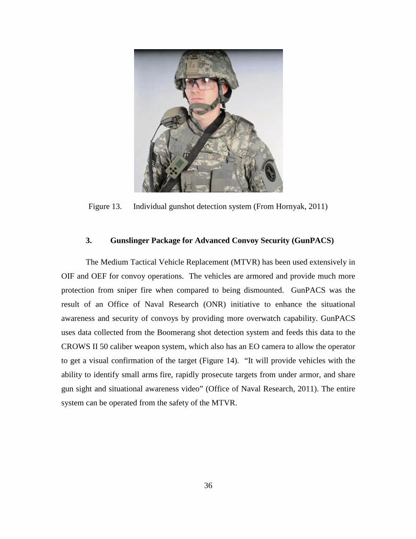
36
Figure 13. Individual gunshot detection system (From Hornyak, 2011)
3. Gunslinger Package for Advanced Convoy Security (GunPACS)
The Medium Tactical Vehicle Replacement (MTVR) has been used extensively in
OIF and OEF for convoy operations. The vehicles are armored and provide much more
protection from sniper fire when compared to being dismounted. GunPACS was the
result of an Office of Naval Research (ONR) initiative to enhance the situational
awareness and security of convoys by providing more overwatch capability. GunPACS
uses data collected from the Boomerang shot detection system and feeds this data to the
CROWS II 50 caliber weapon system, which also has an EO camera to allow the operator
to get a visual confirmation of the target (Figure 14). “It will provide vehicles with the
ability to identify small arms fire, rapidly prosecute targets from under armor, and share
gun sight and situational awareness video” (Office of Naval Research, 2011). The entire
system can be operated from the safety of the MTVR.
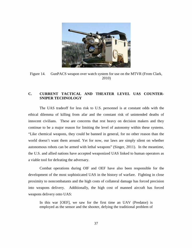
37
Figure 14. GunPACS weapon over watch system for use on the MTVR (From Clark, 2010)
C. CURRENT TACTICAL AND THEATER LEVEL UAS COUNTER-SNIPER TECHNOLOGY
The UAS tradeoff for less risk to U.S. personnel is at constant odds with the
ethical dilemma of killing from afar and the constant risk of unintended deaths of
innocent civilians. These are concerns that rest heavy on decision makers and they
continue to be a major reason for limiting the level of autonomy within these systems.
“Like chemical weapons, they could be banned in general, for no other reason than the
world doesn’t want them around. Yet for now, our laws are simply silent on whether
autonomous robots can be armed with lethal weapons” (Singer, 2011). In the meantime,
the U.S. and allied nations have accepted weaponized UAS linked to human operators as
a viable tool for defeating the adversary.
Combat operations during OIF and OEF have also been responsible for the
development of the most sophisticated UAS in the history of warfare. Fighting in close
proximity to noncombatants and the high costs of collateral damage has forced precision
into weapons delivery. Additionally, the high cost of manned aircraft has forced
weapons delivery onto UAS:
In this war [OEF], we saw for the first time an UAV (Predator) is employed as the sensor and the shooter, defying the traditional problem of
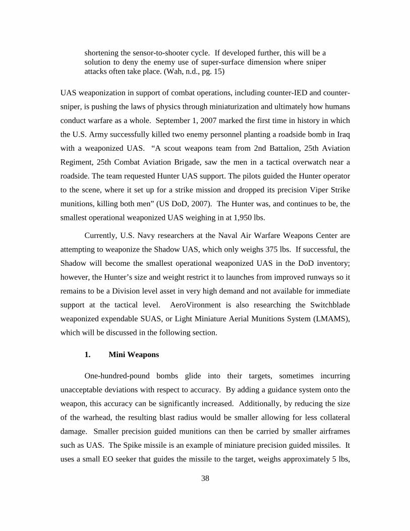
38
shortening the sensor-to-shooter cycle. If developed further, this will be a solution to deny the enemy use of super-surface dimension where sniper attacks often take place. (Wah, n.d., pg. 15)
UAS weaponization in support of combat operations, including counter-IED and counter-
sniper, is pushing the laws of physics through miniaturization and ultimately how humans
conduct warfare as a whole. September 1, 2007 marked the first time in history in which
the U.S. Army successfully killed two enemy personnel planting a roadside bomb in Iraq
with a weaponized UAS. “A scout weapons team from 2nd Battalion, 25th Aviation
Regiment, 25th Combat Aviation Brigade, saw the men in a tactical overwatch near a
roadside. The team requested Hunter UAS support. The pilots guided the Hunter operator
to the scene, where it set up for a strike mission and dropped its precision Viper Strike
munitions, killing both men” (US DoD, 2007). The Hunter was, and continues to be, the
smallest operational weaponized UAS weighing in at 1,950 lbs.
Currently, U.S. Navy researchers at the Naval Air Warfare Weapons Center are
attempting to weaponize the Shadow UAS, which only weighs 375 lbs. If successful, the
Shadow will become the smallest operational weaponized UAS in the DoD inventory;
however, the Hunter’s size and weight restrict it to launches from improved runways so it
remains to be a Division level asset in very high demand and not available for immediate
support at the tactical level. AeroVironment is also researching the Switchblade
weaponized expendable SUAS, or Light Miniature Aerial Munitions System (LMAMS),
which will be discussed in the following section.
1. Mini Weapons
One-hundred-pound bombs glide into their targets, sometimes incurring
unacceptable deviations with respect to accuracy. By adding a guidance system onto the
weapon, this accuracy can be significantly increased. Additionally, by reducing the size
of the warhead, the resulting blast radius would be smaller allowing for less collateral
damage. Smaller precision guided munitions can then be carried by smaller airframes
such as UAS. The Spike missile is an example of miniature precision guided missiles. It
uses a small EO seeker that guides the missile to the target, weighs approximately 5 lbs,
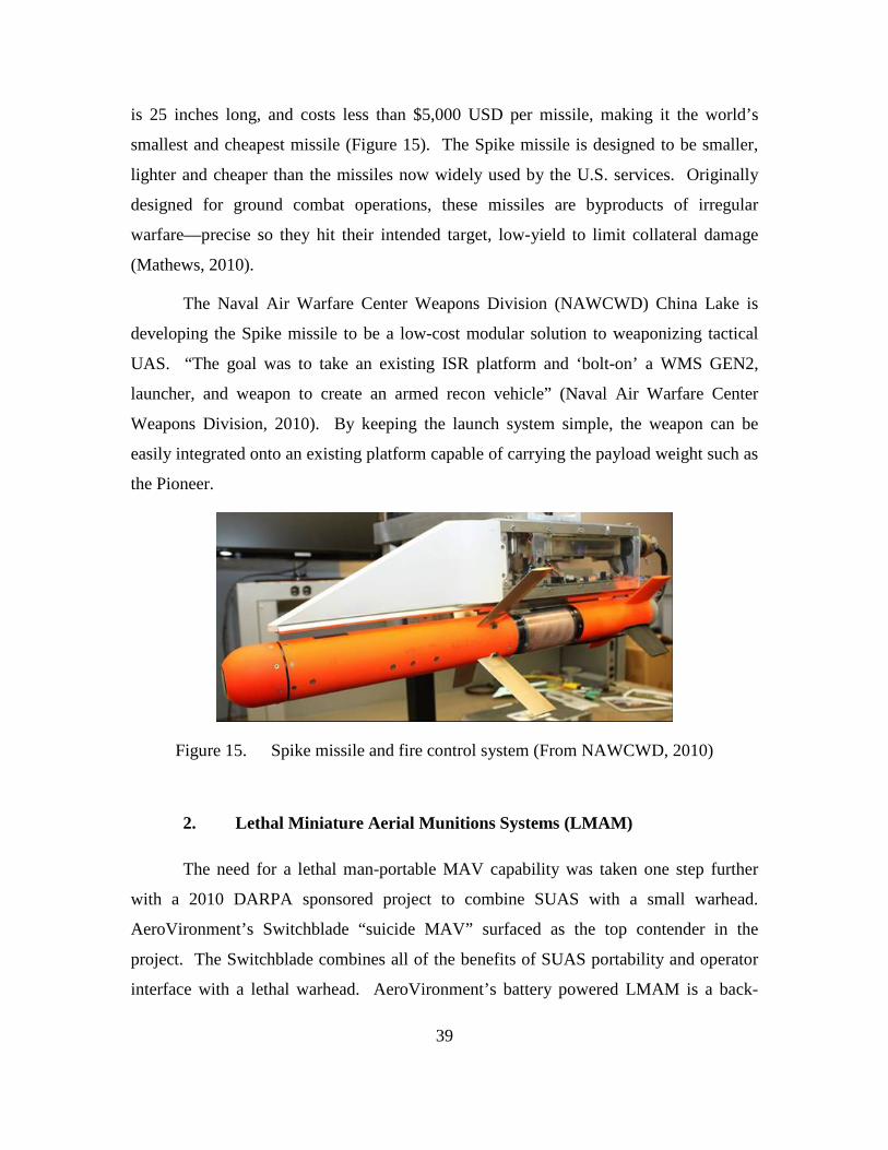
39
is 25 inches long, and costs less than $5,000 USD per missile, making it the world’s
smallest and cheapest missile (Figure 15). The Spike missile is designed to be smaller,
lighter and cheaper than the missiles now widely used by the U.S. services. Originally
designed for ground combat operations, these missiles are byproducts of irregular
warfare—precise so they hit their intended target, low-yield to limit collateral damage
(Mathews, 2010).
The Naval Air Warfare Center Weapons Division (NAWCWD) China Lake is
developing the Spike missile to be a low-cost modular solution to weaponizing tactical
UAS. “The goal was to take an existing ISR platform and ‘bolt-on’ a WMS GEN2,
launcher, and weapon to create an armed recon vehicle” (Naval Air Warfare Center
Weapons Division, 2010). By keeping the launch system simple, the weapon can be
easily integrated onto an existing platform capable of carrying the payload weight such as
the Pioneer.
Figure 15. Spike missile and fire control system (From NAWCWD, 2010)
2. Lethal Miniature Aerial Munitions Systems (LMAM)
The need for a lethal man-portable MAV capability was taken one step further
with a 2010 DARPA sponsored project to combine SUAS with a small warhead.
AeroVironment’s Switchblade “suicide MAV” surfaced as the top contender in the
project. The Switchblade combines all of the benefits of SUAS portability and operator
interface with a lethal warhead. AeroVironment’s battery powered LMAM is a back-

40
packable, tube-launched, expendable weapon (Figure 16). The vehicle has an EO guided
system, and is fitted with a small warhead. The weapon is able to loiter quietly within
short range of the target for a limited time, waiting for optimal conditions to attack, while
maintaining constant communications with the operator, transferring live video of the
target below (Defense Update, 2010). LMAMs such as Switchblade retain a “man in the
loop” command and control, which allows operators the ability to abort the mission
during the majority of the mission. This differs from traditional guided munitions that
cannot be aborted once they are delivered from the air vehicle. While autonomous in
flight, the LMAM is not autonomous in targeting phase of flight.
Figure 16. AeroVironment Switchblade LMAM (From Defense-Update, 2010)
With all systems there are tradeoffs and the LMAMs are no exception.
Comparing the Switchblade’s lethal effects with the 40mm grenade commonly used in
hand-launched systems, such as the M203 grenade launcher, the Switchblade would
produce a kill radius of approximately 5m, which would be a very effective capability
against a small enemy IED emplacement team or a sniper. This warhead would require a
payload weight of approximately 0.5lb to 1.0lb of explosive—undoubtedly taxing on the
MAV’s small battery powered endurance therefore restricting the ISR capability to

41
strictly locking on to a target as quickly as possible. The endurance of a MAV carrying
this size payload would not allow much time to actively search for a target. The target
would probably have to be under current observation. Additionally, once the MAV is
flown into a target it is gone. This means that the operators would require a second UAS
in order to maintain an organic ISR capability or to bring multiple LMAMs on the
mission. If the LMAM is launched and the mission is subsequently aborted, the operators
will be left with an unexploded ordinance scenario. Nevertheless, LMAM are the
smallest lethal UAVs engineered to date. However, the tradeoffs discussed have been the
driving factors for this research and possible systems that may meet these requirements
while also preserving the best attributes of current ISR systems are explored.

42
THIS PAGE INTENTIONALLY LEFT BLANK

43
IV. WEAPONIZED MAN-PORTABLE UAS DESIGN REQUIREMENTS
A. INTRODUCTION
Prior to this chapter, literature reviews and resources found within DoD and
throughout the internet were explored to explore current SUAS technology and the sniper
problem. This identified limitations in current capabilities in countering the sniper
problem and as a result inferred the systems engineering approach to identify design
requirements of weaponizing SUAS in an attempt to fill this gap. This chapter begins
with an overview of the systems engineering process and how it can specifically aid in
the development of these design requirements. Next the basic design requirements are
leveraged to develop conceptual design requirements and a proof of concept model
validated through field experimentation. The next section of the chapter focuses on the
results of the experiments and provided refinements in the design requirements. The
chapter concludes with design requirement comparisons taking into consideration the
advantages and disadvantages to the possible system components.
B. A SYSTEMS ENGINEERING APPROACH TO IDENTIFYING REQUIREMENTS
1. The Systems Engineering Process
The systems engineering process begins with an identified problem or
requirement and continues through the design and fielding of a system that will
ultimately solve the problem. Systems engineering methods can differ depending on the
systems to be designed and whether they are applied to the civilian sector or to the DoD.
However, this research utilized those methods outlined in the Defense Acquisition
University shown in Figure 17 combined with those of Benjamin S. Blanchard shown in
Figure 18. Additionally, certain technological trends throughout the systems engineering

44
field have complicated the overall process. These trends include constantly changing
requirements, more emphasis on faster fielding through COTS components, a shift to
emphasizing systems, and interfacing multiple systems to function together as a system
of systems (SOS).
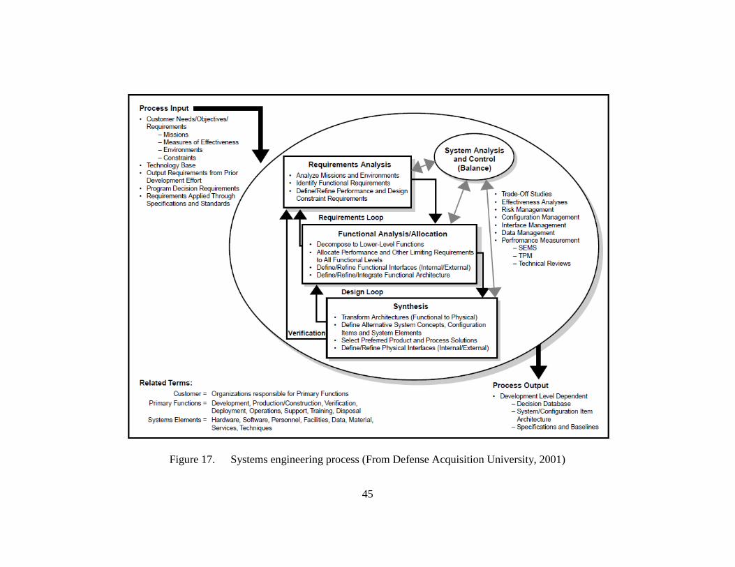
45
Figure 17. Systems engineering process (From Defense Acquisition University, 2001)
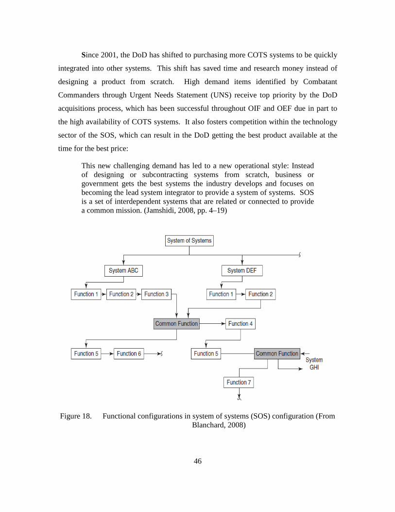
46
Since 2001, the DoD has shifted to purchasing more COTS systems to be quickly
integrated into other systems. This shift has saved time and research money instead of
designing a product from scratch. High demand items identified by Combatant
Commanders through Urgent Needs Statement (UNS) receive top priority by the DoD
acquisitions process, which has been successful throughout OIF and OEF due in part to
the high availability of COTS systems. It also fosters competition within the technology
sector of the SOS, which can result in the DoD getting the best product available at the
time for the best price:
This new challenging demand has led to a new operational style: Instead of designing or subcontracting systems from scratch, business or government gets the best systems the industry develops and focuses on becoming the lead system integrator to provide a system of systems. SOS is a set of interdependent systems that are related or connected to provide a common mission. (Jamshidi, 2008, pp. 4–19)
Figure 18. Functional configurations in system of systems (SOS) configuration (From Blanchard, 2008)
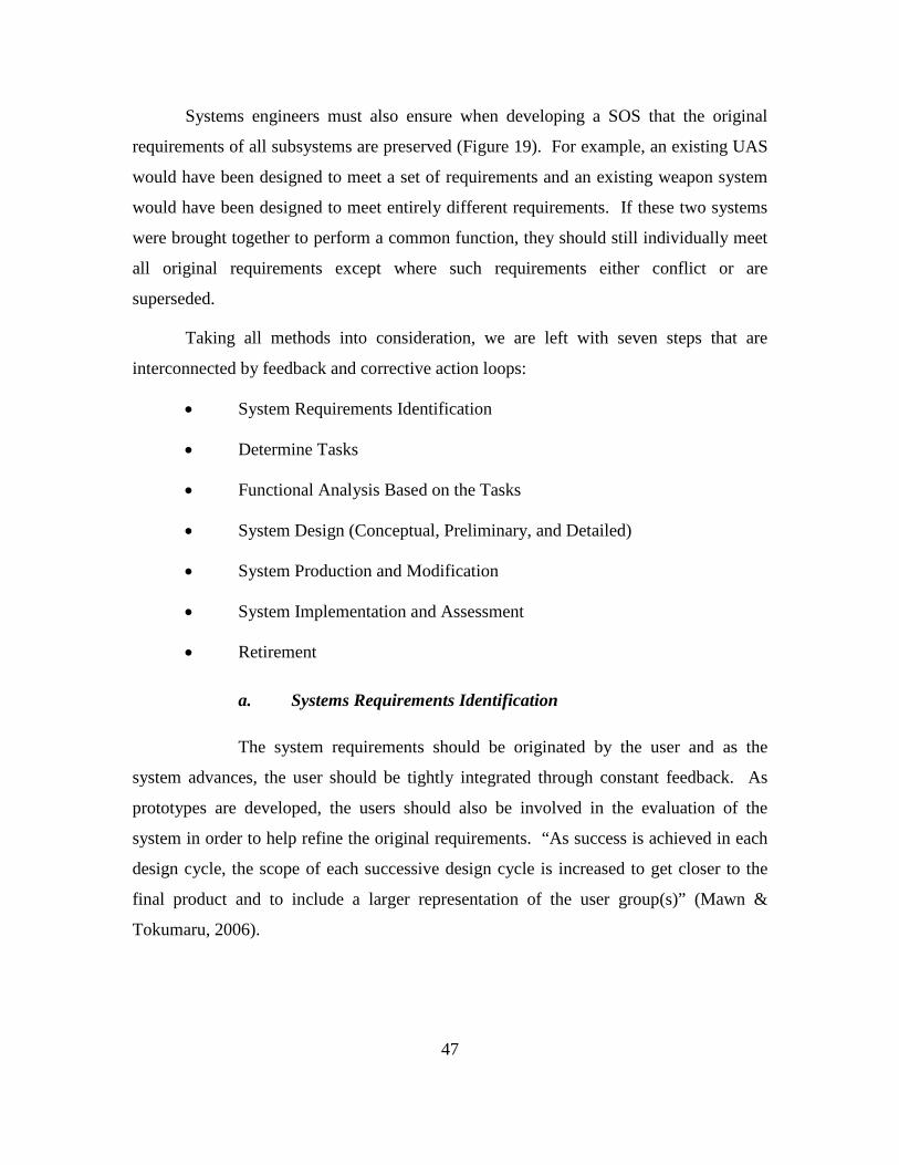
47
Systems engineers must also ensure when developing a SOS that the original
requirements of all subsystems are preserved (Figure 19). For example, an existing UAS
would have been designed to meet a set of requirements and an existing weapon system
would have been designed to meet entirely different requirements. If these two systems
were brought together to perform a common function, they should still individually meet
all original requirements except where such requirements either conflict or are
superseded.
Taking all methods into consideration, we are left with seven steps that are
interconnected by feedback and corrective action loops:
• System Requirements Identification
• Determine Tasks
• Functional Analysis Based on the Tasks
• System Design (Conceptual, Preliminary, and Detailed)
• System Production and Modification
• System Implementation and Assessment
• Retirement
a. Systems Requirements Identification
The system requirements should be originated by the user and as the
system advances, the user should be tightly integrated through constant feedback. As
prototypes are developed, the users should also be involved in the evaluation of the
system in order to help refine the original requirements. “As success is achieved in each
design cycle, the scope of each successive design cycle is increased to get closer to the
final product and to include a larger representation of the user group(s)” (Mawn &
Tokumaru, 2006).
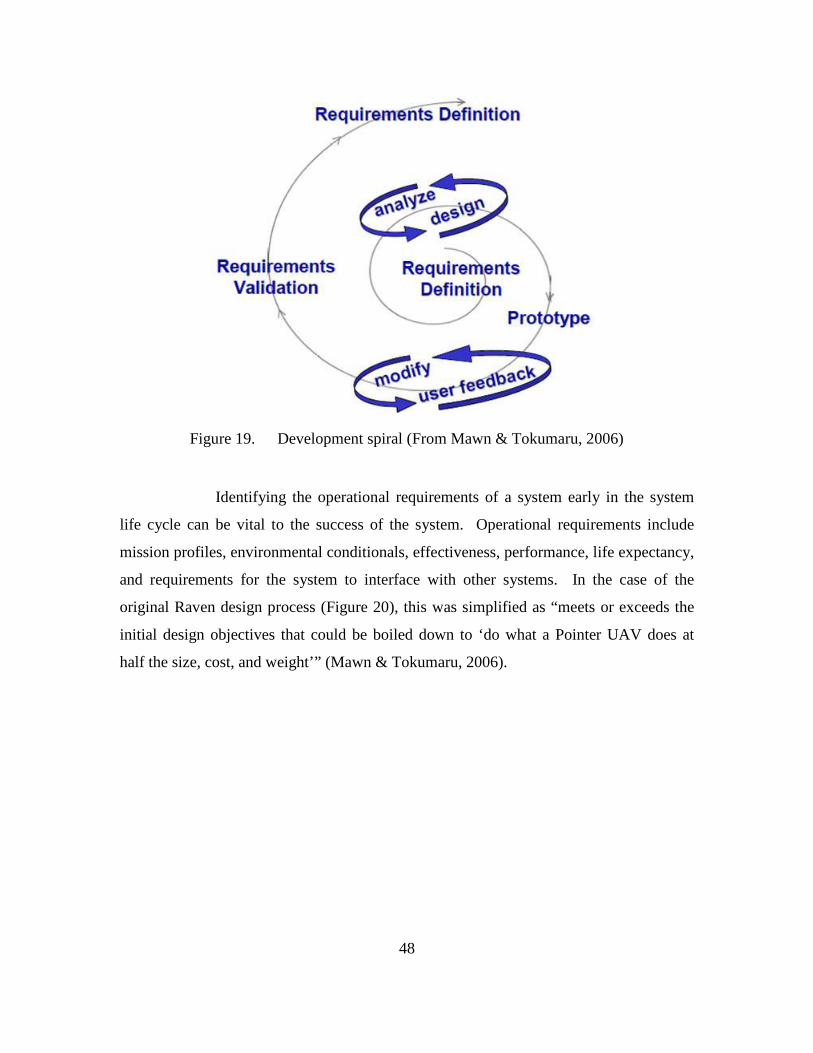
48
Figure 19. Development spiral (From Mawn & Tokumaru, 2006)
Identifying the operational requirements of a system early in the system
life cycle can be vital to the success of the system. Operational requirements include
mission profiles, environmental conditionals, effectiveness, performance, life expectancy,
and requirements for the system to interface with other systems. In the case of the
original Raven design process (Figure 20), this was simplified as “meets or exceeds the
initial design objectives that could be boiled down to ‘do what a Pointer UAV does at
half the size, cost, and weight’” (Mawn & Tokumaru, 2006).
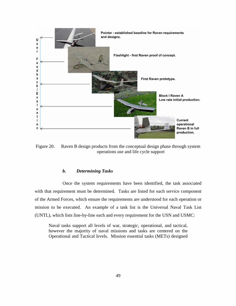
49
Figure 20. Raven B design products from the conceptual design phase through system operations use and life cycle support
b. Determining Tasks
Once the system requirements have been identified, the task associated
with that requirement must be determined. Tasks are listed for each service component
of the Armed Forces, which ensure the requirements are understood for each operation or
mission to be executed. An example of a task list is the Universal Naval Task List
(UNTL), which lists line-by-line each and every requirement for the USN and USMC:
Naval tasks support all levels of war, strategic, operational, and tactical, however the majority of naval missions and tasks are centered on the Operational and Tactical levels. Mission essential tasks (METs) designed

50
to specifically support a COCOM mission (or JMETL) will most likely be at the operational (OP) and tactical (NTA/MCT) levels. (Department of the Navy NUTL, 2007)
Tasks define discrete events and do not detail the specific unit or piece of equipment to
be used in the task.
An example of a task that would drive the requirement for SUAS
integration into tactical units is Marine Corps Task (MCT) 2.2.1.2—Conduct Area
Reconnaissance, which states: “To conduct a form of reconnaissance that is a directed
effort to obtain detailed information concerning the terrain or enemy activity within a
prescribed area, such as a town, ridgeline, woods, or other feature critical to operations”
(Department of the Navy NUTL, 2007, pg. 262). SUAS have been identified as force
multipliers in the execution of ISR which partially fulfills this task and therefore the
requirement for SUAS.
c. Functional Analysis
Functional analysis is the process of translating system requirements into
detailed design criteria, along with the identification of specific resource requirements at
the subsystem level and below. One starts with an abstraction of the customer need(s)
and works down to identifying the requirements for hardware, software, people, facilities,
data, and so on. The first step is to identify the functions that the system must perform,
along with the supporting functions that are needed for this to happen. Functional
analysis entails the construction a functional flow diagram at the system level. Then
engineers must identify design functions, test functions, production functions, operational
functions, maintenance functions, and retirement/disposal functions as necessary.
Finally, each function must be evaluated in terms of input-output requirements,
constraints, and the resources required in order to accomplish the function (Blanchard,
2008).

51
Figure 21. IDEF0 template to identify resource requirements (From Blanchard, 2008)
Functional analysis is first accomplished at the top-level as the customer need is
defined during the early stages of conceptual design. This involves identifying and
describing the functions that the system must accomplish. The IDEF0 as depicted in
Figure 21 is a general functional resource analysis tool commonly used in systems
engineering to visually represent the inputs and outputs of a system. The analysis effort
continues throughout conceptual design and preliminary design, to the depth required to
provide the necessary visibility for the design of system elements and components. A
good functional baseline is established in order to provide a foundation for all follow-on
design activities. In this respect, accomplishing functional analysis is a critical step in the
system engineering process and serves to prevent functional oversight through early
identification of the various levels of functions and how they affect not only the system in
question, but how they may affect interacting systems.
52
d. System Design
The design process of any system begins with a clearly identified set of
requirements. Figure 22 depicts Blanchard’s major steps in system design and
development. It begins with the conceptual design phase where the designers will
identify additional design metrics such as technical performance measures, operational
requirements, and system specifications. As the system progresses into the preliminary
system design phase, the engineers can continue to incorporate additional changes into
the system without much cost. However, as the design progresses into the development
phase each change will come at increasingly higher costs to the design process. Once in
the production phase, changes can be made but extreme care must be taken to ensure the
changes do not adversely affect the system’s ability to meet the original requirements.

53
Figure 22. Major steps of system design and development (From Blanchard, 2008)
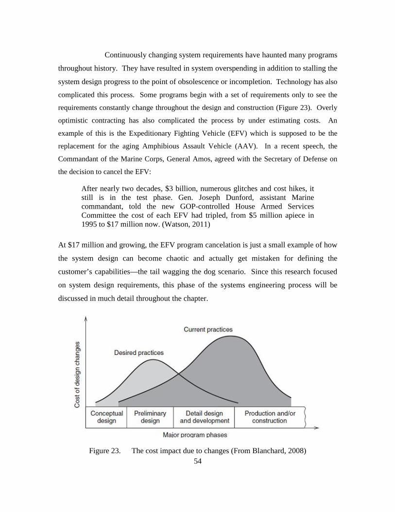
54
Continuously changing system requirements have haunted many programs
throughout history. They have resulted in system overspending in addition to stalling the
system design progress to the point of obsolescence or incompletion. Technology has also
complicated this process. Some programs begin with a set of requirements only to see the
requirements constantly change throughout the design and construction (Figure 23). Overly
optimistic contracting has also complicated the process by under estimating costs. An
example of this is the Expeditionary Fighting Vehicle (EFV) which is supposed to be the
replacement for the aging Amphibious Assault Vehicle (AAV). In a recent speech, the
Commandant of the Marine Corps, General Amos, agreed with the Secretary of Defense on
the decision to cancel the EFV:
After nearly two decades, $3 billion, numerous glitches and cost hikes, it still is in the test phase. Gen. Joseph Dunford, assistant Marine commandant, told the new GOP-controlled House Armed Services Committee the cost of each EFV had tripled, from $5 million apiece in 1995 to $17 million now. (Watson, 2011)
At $17 million and growing, the EFV program cancelation is just a small example of how
the system design can become chaotic and actually get mistaken for defining the
customer’s capabilities—the tail wagging the dog scenario. Since this research focused
on system design requirements, this phase of the systems engineering process will be
discussed in much detail throughout the chapter.
Figure 23. The cost impact due to changes (From Blanchard, 2008)
55
C. TNT/CBE 11-2 EXPERIMENTS MAC DILL AFB AUX FIELD (AVON PARK AIR FORCE RANGE) RQ-11B RAVEN
The Naval Postgraduate School in partnership with USSOCOM sponsored the
Capability Based Experiments (CBE 11-2) from 21–26 February 2011. The event
provides an environment for numerous DoD, NPS and civilian contractor organizations
such as AeroVironment, WinTec, and Boeing to conduct experiments and to collaborate
with other participants while getting constant feedback from active duty members of
component special operations communities. This experiment was conducted at Mac Dill
AFB Aux Field (Avon Park Air Force Range (APAFR) ICAO: KAGR (Figure 25) from
February 22–24. Airfield Elevation 68 ft (21 m) during the hours of 1200–1700.
Weather conditions were mostly sunny, maximum temperatures 82 degrees Fahrenheit,
surface winds 3–10 knots.
This was the first exploratory experiment in identifying the required design
characteristics for a man-portable weaponized unmanned aerial system (UAS) in support
of counter-sniper operations. The focus of these efforts during CBE 11-2 was to mount a
small nonlethal weaponized proof of concept payload onto the RQ-11 B Raven UAS.
The Raven was chosen because of current availability within the operating forces (U.S.
and Allies) and its continuing success in support of combat operations during OIF and
OEF. Raven SOPs are mature and the operator duties have been clearly defined, which
helps in identifying the effects of additional workload to the operators during the
experiment. However, the vehicle’s high portability also severely limits its payload
capacity, which made it an extremely challenging platform to add additional capabilities
to.
In order to safely conduct this type of experiment, an alternative to immediately
testing lethal payloads was required. Although there were numerous possibilities,
paintballs were chosen as a proof of concept because they meet safety requirements and
provide easily identifiable impact marks. At a muzzle velocity of 330 ft/s, paintballs pose
much less risk to bodily harm than a typical .22-caliber rifle at 3000 ft/s. Payload
capacity and aerodynamic drag were the limiting factors in the payload design but of
most concern was the weight. COTS multiple-shot paintball guns are extremely heavy,
56
usually weighing in over 1,500 grams without the air supply to propel the rounds.
Normally, these guns rely on high pressure air (HPA) to operate but the smallest
available HPA tank weighs 440 grams and this would not be feasible. A single-shot
paintball gun was chosen in order to reduce the propellant requirement to 12 gram liquid
CO2 canisters, which weigh only 30 grams when full. Some time was spent modifying
the gun to reduce unnecessary weight and to add in a trigger that could be remotely fired
through a wireless signal. Additionally, the gun was originally configured to fire .68
caliber paintballs; however, this was replaced with a carbon fiber .50-caliber barrel to
save weight and gain some accuracy with the smaller caliber paintballs. Figure 24 depicts
the before and after weights of the gun. Figure 26 is a diagram of the payload which was
placed over the Raven battery compartment. Specific questions during the experiment
were:
1. The trigger mechanism controllability, functionality, operator workload, and
timing with the rest of the communications system.
2. The armed RQ-11B flight characteristics at various profiles.
3. The armed RQ-11B loiter time at various profiles.
4. The bore-sighted camera functionality and usability with the rest of the
communications systems.
5. The time required to launch, shoot, and recover the RQ-11B.
6. When fired, how accurate was the nonlethal payload with respect to target
location.

57
Figure 24. Before and after weights in grams of the modified nonlethal paintball gun used as UAS proof of concept payload in the experiments
Figure 25. RQ-11B experiment at Mac Dill Aux Field, Avon Park, FL
58
1. Quantitative/Qualitative Results
The first test was to check the trigger mechanism. Specifically we wanted to
ensure the high power output of the Raven communications link would not jam the lower
power frequency used by the remote controlled gun trigger. The triggering system was
implemented using COTS Spektrum 2.4 GHz, 6-Channel receiver and a COTS Spektrum
handheld RC Radio. The safety mechanism was designed so the operator would be
required to hold down a switch to disable the safety, and press a second switch to fire.
The trigger was tested successfully.
The second test was to check the flight characteristics of the Raven while carrying
the small nonlethal payload. The payload was designed to mount over the Raven battery
pack compartment on the port side, which also balanced the load with the aircraft cg
(Figure 26). Maximum payload weight for the Raven is approximately 16 oz. and our
payload weight (camera, gun, and trigger) was 240 grams (~8.5 oz.). This was a major
concern for power but the payload also added drag and asymmetrically offset cg from the
aircraft centerline. The first launch proved that the Raven could handle the weight of the
payload at 68 ft. MSL launch and recovery elevation, and the added drag did not
noticeably affect the flight performance.
Raven loiter time with the payload attached was not tested specifically due to
experiment time constraints and because multiple experiments using the Raven were
being conducted simultaneously. However, the battery was able to support five flights of
launch-fire-recover cycles on a single charge, which would be effective in employing the
UAS against a sniper under the constraints of the scenario.
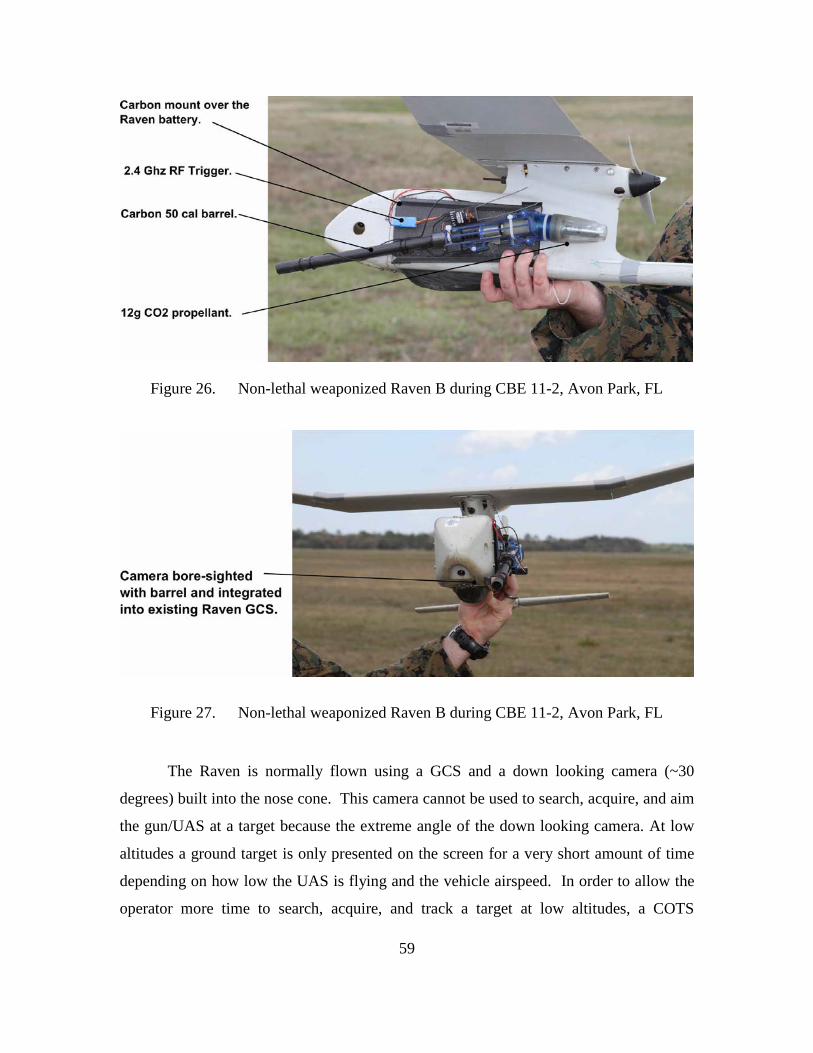
59
Figure 26. Non-lethal weaponized Raven B during CBE 11-2, Avon Park, FL
Figure 27. Non-lethal weaponized Raven B during CBE 11-2, Avon Park, FL
The Raven is normally flown using a GCS and a down looking camera (~30
degrees) built into the nose cone. This camera cannot be used to search, acquire, and aim
the gun/UAS at a target because the extreme angle of the down looking camera. At low
altitudes a ground target is only presented on the screen for a very short amount of time
depending on how low the UAS is flying and the vehicle airspeed. In order to allow the
operator more time to search, acquire, and track a target at low altitudes, a COTS

60
lightweight (~2 gram) 60 degrees FOV camera was mounted onto the composite barrel.
This could then serve as the primary camera to both fly and search for the targets (Figure
27). The camera was rather easily integrated into the Raven avionics and GCS video and
was bore sighted so that a cross-hair on the operator’s HUD corresponded with where the
round would hit.
The forward looking camera allowed the operator to fly from first person video
(FPV) using only the video (not looking at the aircraft itself) and track the target once it
appeared in the screen. The video feed was also viewed from a second screen where the
Payload Operator (PO) could see the exact same image as the pilot and could then switch
off the gun safety and hit the trigger to fire the weapon. Raven operators are not used to
flying FPV; however, the WinTec operator flying the Raven during this experiment
surprisingly only needed a few minutes and 3 passes to reach his comfort level and to
engage the target. A man sized target was marked in bright orange on a 4x8 ft sheet of
plywood and stood upright against the side of a High Mobility Multipurpose Wheeled
Vehicle (HMMWV) to simulate an enemy sniper standing near a parked car. The target
can be seen in Figures 28 and 29.
Figure 28. Target used in the nonlethal weaponized RQ-11B experiment during CBE 11-2, Avon Park, FL

61
Figure 29. First person RQ-11B pilot and trigger operator view on RQ-11B GCS flying the nonlethal weaponized RQ-11B firing at man-sized target during
CBE 11-2, Avon Park, FL
The flight profile consisted of a 100–150 ft pattern until final approach when the
aircraft started a decent at the target. Neither of the operators looked up from their video
displays during the flight in order to simulate attacking a sniper with enough standoff that
the Raven operator would not have direct un-aided visual LOS to the sniper or the Raven.
The Raven is depicted moments after firing at the target in Figure 29, and a screen
capture from the video feed used by the operators, a fraction of a second after the trigger
was pulled showing the paint ball departing the barrel. The altitudes at the time of trigger
pull varied 20 ft ± 5 ft, with each flight depending on the approach profile and wind
gusts, and the lateral separation from the target was 80 ft ± 20 ft. The gun was tested for
accuracy while bore sighting it prior to the experiment at a range of 80 ft against a target
smaller than a person.
Time to launch and recover the Raven was difficult to calculate because of the
experimental gun. Because the gun was the lowest point on the aircraft in flight and
because the Raven is recovered by entering a deep stall or manual “crash,” the gun barrel
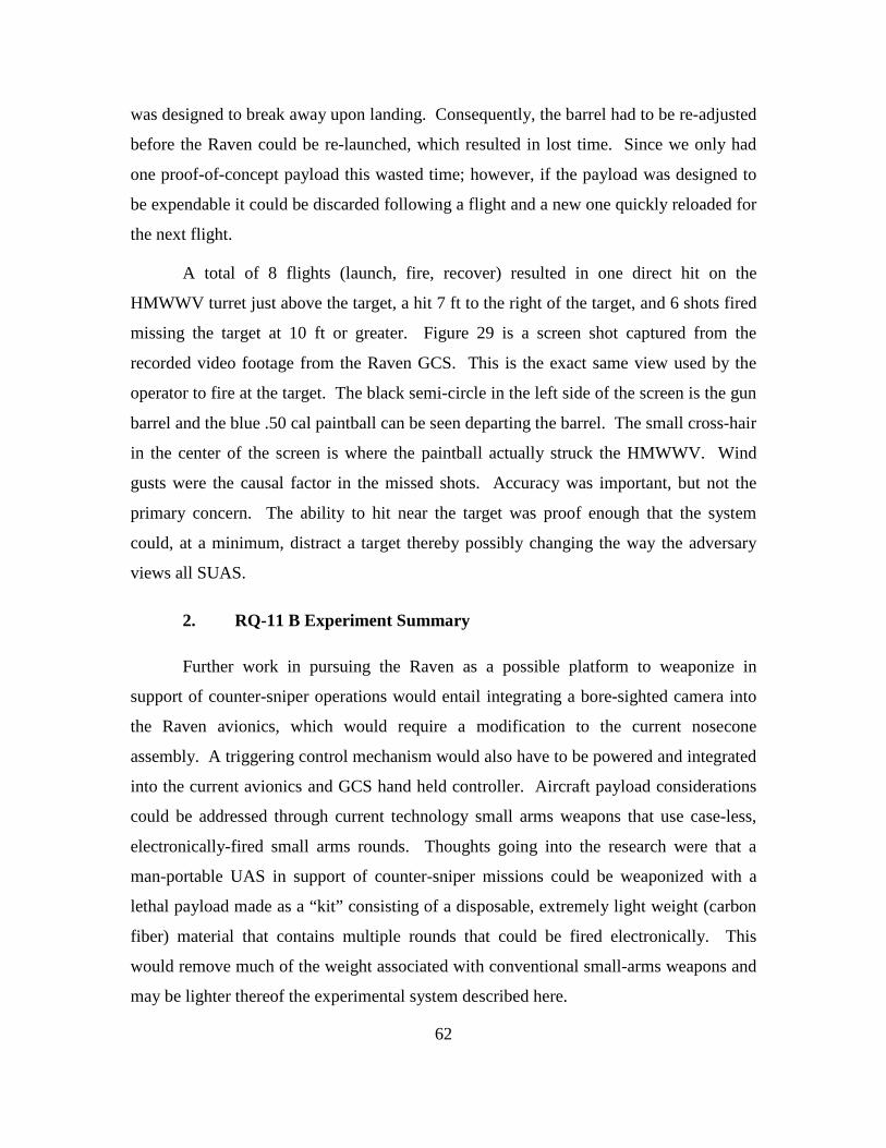
62
was designed to break away upon landing. Consequently, the barrel had to be re-adjusted
before the Raven could be re-launched, which resulted in lost time. Since we only had
one proof-of-concept payload this wasted time; however, if the payload was designed to
be expendable it could be discarded following a flight and a new one quickly reloaded for
the next flight.
A total of 8 flights (launch, fire, recover) resulted in one direct hit on the
HMWWV turret just above the target, a hit 7 ft to the right of the target, and 6 shots fired
missing the target at 10 ft or greater. Figure 29 is a screen shot captured from the
recorded video footage from the Raven GCS. This is the exact same view used by the
operator to fire at the target. The black semi-circle in the left side of the screen is the gun
barrel and the blue .50 cal paintball can be seen departing the barrel. The small cross-hair
in the center of the screen is where the paintball actually struck the HMWWV. Wind
gusts were the causal factor in the missed shots. Accuracy was important, but not the
primary concern. The ability to hit near the target was proof enough that the system
could, at a minimum, distract a target thereby possibly changing the way the adversary
views all SUAS.
2. RQ-11 B Experiment Summary
Further work in pursuing the Raven as a possible platform to weaponize in
support of counter-sniper operations would entail integrating a bore-sighted camera into
the Raven avionics, which would require a modification to the current nosecone
assembly. A triggering control mechanism would also have to be powered and integrated
into the current avionics and GCS hand held controller. Aircraft payload considerations
could be addressed through current technology small arms weapons that use case-less,
electronically-fired small arms rounds. Thoughts going into the research were that a
man-portable UAS in support of counter-sniper missions could be weaponized with a
lethal payload made as a “kit” consisting of a disposable, extremely light weight (carbon
fiber) material that contains multiple rounds that could be fired electronically. This
would remove much of the weight associated with conventional small-arms weapons and
may be lighter thereof the experimental system described here.

63
D. PELICAN QUADROTOR EXPERIMENT CAMP ROBERTS, CA
The Naval Postgraduate School routinely conducts experimentation at McMillan
Airfield located in Camp Roberts Army National Guard Training site, CA. McMillan
Airfield (FAA ID CA62) has a 3500 x 60 ft. / 1067 x 18 m asphalt runway, which
provides a perfect environment for testing a multitude of UAS. This experiment was an
individual experiment conducted March 21, 2011 between the hours of 1200–1700. The
weather conditions were partly cloudy with variable winds 3–10 knots and the
temperature was a high of 62 degrees Fahrenheit.
This was the second experiment in identifying the required design characteristics
for a weaponized man-portable UAS in support of counter-sniper operations and the first
experiment using a VTOL UAS. The purpose of this experiment was to weaponize a
COTS quadrotor with the same nonlethal paintball gun used on the RQ-11 B experiment
in order to compare the difference between a man-portable fix wing UAS and a man-
portable VTOL UAS. The Pelican quadrotor was chosen, primarily for its availability
within NPS for autonomy research and its autopilot capability. It also has a respectable
maximum payload capacity of 500 grams. The same nonlethal payload that was used in
the Raven experiment was also used in this experiment through slight modifications to
test the concept of a single kit which could be added to more than one particular platform.
The same RF links were used to control the trigger servo. The overall objective was to
explore the difference between a VTOL and fixed wing SUAS in a counter-sniper role.
Primary design concerns included the effectiveness of a hover and stare capability
compared to a fixed-wing UAS that is constantly moving forward.
Quadrotor technology has undergone much advancement that has simplified the
once complicated mechanically controlled flight control surfaces—into electronically
controlled signals to the four motors. The rotors at the ends of each axis rotate in the
same direction as each other, while rotating in the opposite direction of the rotors in the
perpendicular axis in order to cancel out the torque. Roll, pitch, yaw, and altitude
changes are all achieved through either increasing or decreasing the speeds of the motors
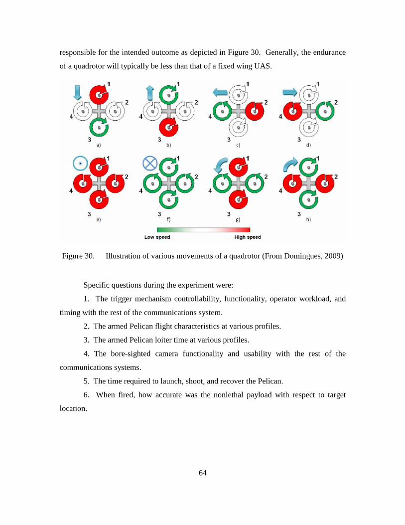
64
responsible for the intended outcome as depicted in Figure 30. Generally, the endurance
of a quadrotor will typically be less than that of a fixed wing UAS.
Figure 30. Illustration of various movements of a quadrotor (From Domingues, 2009)
Specific questions during the experiment were:
1. The trigger mechanism controllability, functionality, operator workload, and
timing with the rest of the communications system.
2. The armed Pelican flight characteristics at various profiles.
3. The armed Pelican loiter time at various profiles.
4. The bore-sighted camera functionality and usability with the rest of the
communications systems.
5. The time required to launch, shoot, and recover the Pelican.
6. When fired, how accurate was the nonlethal payload with respect to target
location.
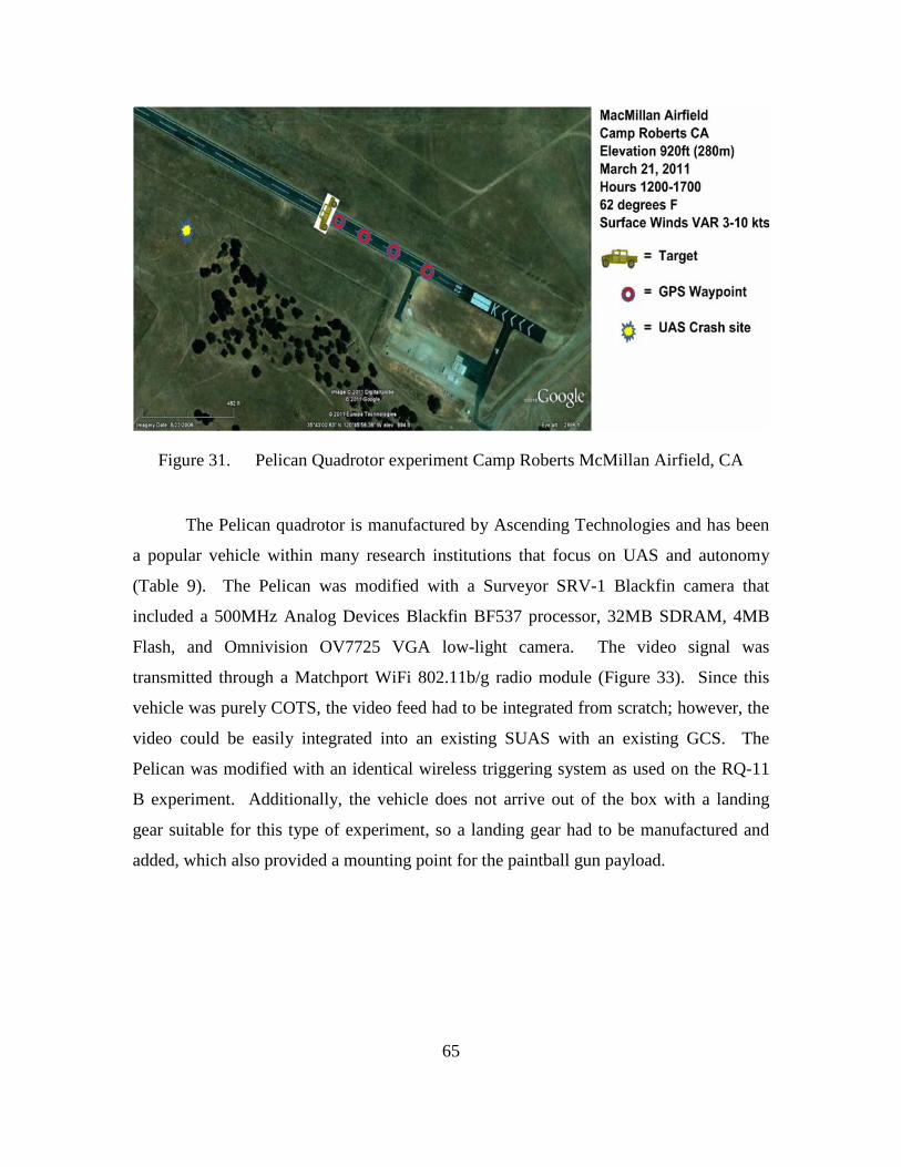
65
Figure 31. Pelican Quadrotor experiment Camp Roberts McMillan Airfield, CA
The Pelican quadrotor is manufactured by Ascending Technologies and has been
a popular vehicle within many research institutions that focus on UAS and autonomy
(Table 9). The Pelican was modified with a Surveyor SRV-1 Blackfin camera that
included a 500MHz Analog Devices Blackfin BF537 processor, 32MB SDRAM, 4MB
Flash, and Omnivision OV7725 VGA low-light camera. The video signal was
transmitted through a Matchport WiFi 802.11b/g radio module (Figure 33). Since this
vehicle was purely COTS, the video feed had to be integrated from scratch; however, the
video could be easily integrated into an existing SUAS with an existing GCS. The
Pelican was modified with an identical wireless triggering system as used on the RQ-11
B experiment. Additionally, the vehicle does not arrive out of the box with a landing
gear suitable for this type of experiment, so a landing gear had to be manufactured and
added, which also provided a mounting point for the paintball gun payload.

66
Table 9. Ascending Technologies Pelican Quadrotor Specifications (From AscTec, 2011)
Design Feature Specification Standard Payloads EO analog or digital wireless camera Range close range Endurance 20 minutes Speed 40 km/h Max Windload 36 km/h Max Payload 500 g Ground Control Station Independent system Launch and Recovery Vertical takeoff and landing
1. Quantitative/Qualitative Results for Pelican
Prior to taking flight, the camera had to be bore sighted with the paintball gun.
This was accomplished at a range of 80 ft at a 2 ft x 3 ft target. Once the camera was
bore sighted, an actual target/scenario was setup much like the one used in the RQ-11
experiment. An HMMWV was placed on the runway and a mannequin was stood out in
front of the vehicle in order to simulate an enemy sniper standing in the open near a
vehicle (Figure 34). Being the first experiment using a quadrotor, the ad hoc ground
control station was established within 150 ft of the target so that the vehicle could be
easily observed as it approached and fired at the target. GPS waypoints were set into the
autopilot in order to have the vehicle takeoff from a distance of approximately 800 ft
from the target, follow the waypoints, come to a hover 80 ft in front of the target (as seen
in Figure 31, fire at the target, and return to the takeoff point via the waypoints.
Unlike the RQ-11B, this UAS did not come with a GCS or an easy way to
integrate video for targeting, which meant the experiment required multiple
communications frequencies, a laptop computer to serve as a GCS, and a laptop computer
to process the video feed for the trigger operator. Ascending Technologies did provide
autopilot software for the Pelican (Figure 32), which enables point and click navigation,
pertinent flight data, and vehicle onboard battery status.
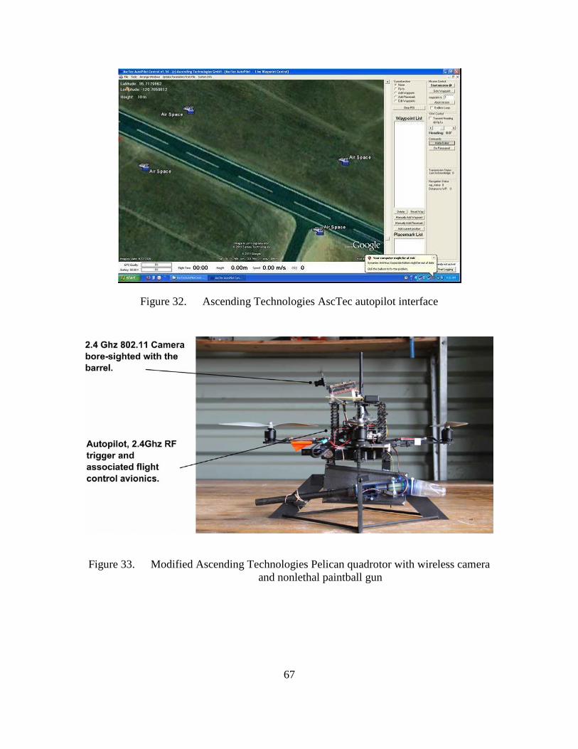
67
Figure 32. Ascending Technologies AscTec autopilot interface
Figure 33. Modified Ascending Technologies Pelican quadrotor with wireless camera and nonlethal paintball gun
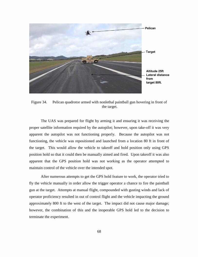
68
Figure 34. Pelican quadrotor armed with nonlethal paintball gun hovering in front of the target.
The UAS was prepared for flight by arming it and ensuring it was receiving the
proper satellite information required by the autopilot; however, upon take-off it was very
apparent the autopilot was not functioning properly. Because the autopilot was not
functioning, the vehicle was repositioned and launched from a location 80 ft in front of
the target. This would allow the vehicle to takeoff and hold position only using GPS
position hold so that it could then be manually aimed and fired. Upon takeoff it was also
apparent that the GPS position hold was not working as the operator attempted to
maintain control of the vehicle over the intended spot.
After numerous attempts to get the GPS hold feature to work, the operator tried to
fly the vehicle manually in order allow the trigger operator a chance to fire the paintball
gun at the target. Attempts at manual flight, compounded with gusting winds and lack of
operator proficiency resulted in out of control flight and the vehicle impacting the ground
approximately 800 ft to the west of the target. The impact did not cause major damage;
however, the combination of this and the inoperable GPS hold led to the decision to
terminate the experiment.
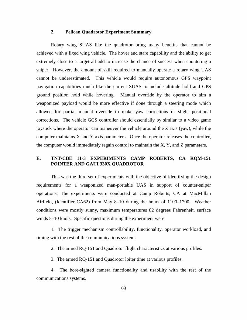
69
2. Pelican Quadrotor Experiment Summary
Rotary wing SUAS like the quadrotor bring many benefits that cannot be
achieved with a fixed wing vehicle. The hover and stare capability and the ability to get
extremely close to a target all add to increase the chance of success when countering a
sniper. However, the amount of skill required to manually operate a rotary wing UAS
cannot be underestimated. This vehicle would require autonomous GPS waypoint
navigation capabilities much like the current SUAS to include altitude hold and GPS
ground position hold while hovering. Manual override by the operator to aim a
weaponized payload would be more effective if done through a steering mode which
allowed for partial manual override to make yaw corrections or slight positional
corrections. The vehicle GCS controller should essentially by similar to a video game
joystick where the operator can maneuver the vehicle around the Z axis (yaw), while the
computer maintains X and Y axis parameters. Once the operator releases the controller,
the computer would immediately regain control to maintain the X, Y, and Z parameters.
E. TNT/CBE 11-3 EXPERIMENTS CAMP ROBERTS, CA RQM-151 POINTER AND GAUI 330X QUADROTOR
This was the third set of experiments with the objective of identifying the design
requirements for a weaponized man-portable UAS in support of counter-sniper
operations. The experiments were conducted at Camp Roberts, CA at MacMillan
Airfield, (Identifier CA62) from May 8–10 during the hours of 1100–1700. Weather
conditions were mostly sunny, maximum temperatures 82 degrees Fahrenheit, surface
winds 5–10 knots. Specific questions during the experiment were:
1. The trigger mechanism controllability, functionality, operator workload, and
timing with the rest of the communications system.
2. The armed RQ-151 and Quadrotor flight characteristics at various profiles.
3. The armed RQ-151 and Quadrotor loiter time at various profiles.
4. The bore-sighted camera functionality and usability with the rest of the
communications systems.

70
5. The time required to launch, shoot, and recover the RQ-151 and Quadrotor.
6. When fired, how accurate was the nonlethal payload with respect to target
location.
The focus of effort during Combat Based Experiments (CBE) 11-3 was to mount
a small nonlethal proof of concept weapon onto the RQ-151 Pointer UAS and
experimental quadrotors. The Pointer was chosen because of its similarities in size,
weight, and payload capacity to AeroVironment’s Puma UAS. The Puma is currently
only available to the Special Operations community but they are in very high demand
with these forces. Acquiring one for experimental purposes was not feasible. There are
currently no Quadrotor SUAS within the DoD, which limited the experiments to
depending on hobby- and research-based vehicles. The only man-portable VTOL SUAS
within DoD is the RQ-16 T-Hawk, which is made by Honeywell. The T-Hawk is also in
very short supply, and is also being heavily used in both Iraq and Afghanistan in support
of combat operations. Furthermore, the T-Hawk weighs approximately 20 lbs, which is
the upper limit the back packable weight of a UAS.
1. Quantitative/Qualitative Results for Pointer
The Pointer, by UAS standards, is an extremely old airplane. AeroVironment
started developing it in 1986 and the first models were delivered to the USMC in 1988
(Table 10). However, it can be flown using the current ground control station used by
Raven, Wasp and Puma, and it also maintains many of the same capabilities. The Pointer
used during the experiments had been modified over the years in order to support other
experiments, which made the exact payload capacity extremely difficult to determine.
Estimates by WinTec were that it could fly with no more than 1.5 lbs, using only one
battery vs. the standard two (the utilized Pointer had been modified to fly using 1 or 2
Raven B batteries).
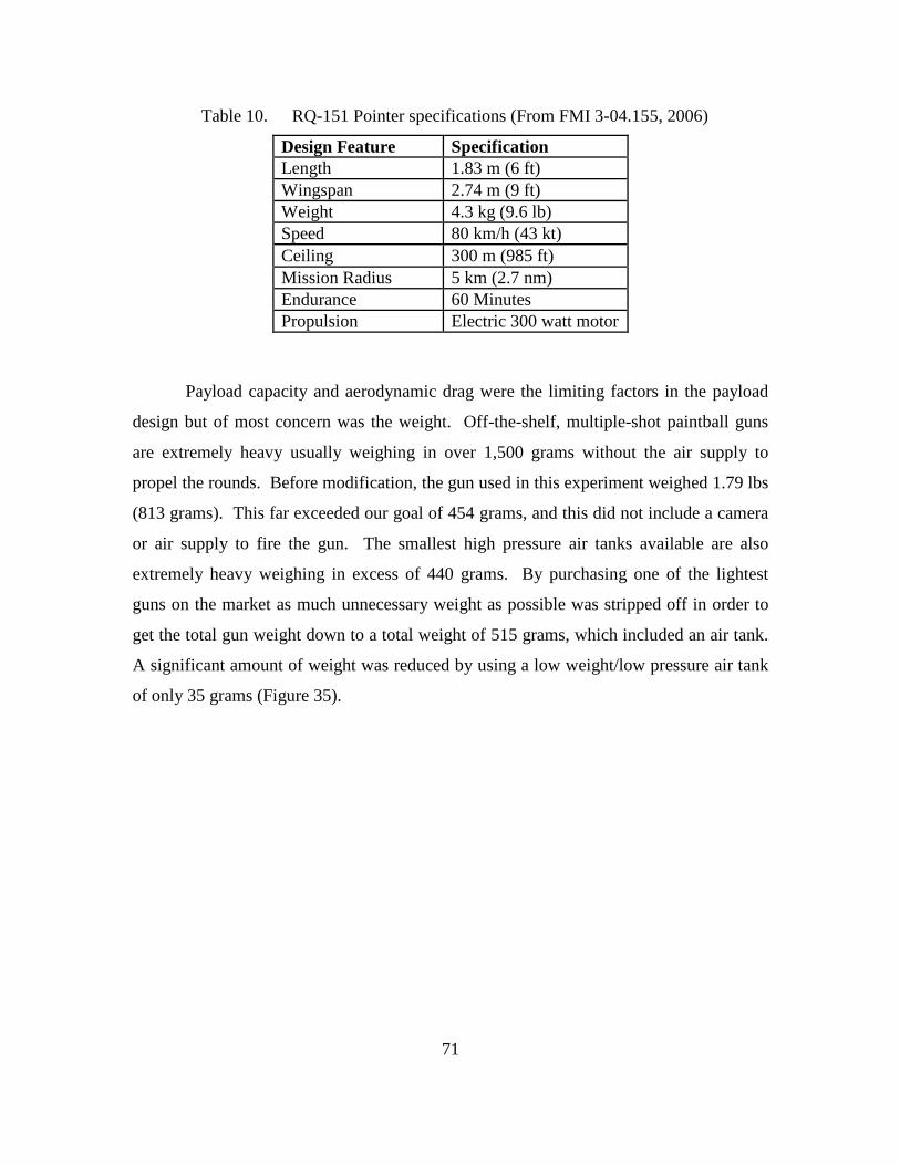
71
Table 10. RQ-151 Pointer specifications (From FMI 3-04.155, 2006)
Design Feature Specification Length 1.83 m (6 ft) Wingspan 2.74 m (9 ft) Weight 4.3 kg (9.6 lb) Speed 80 km/h (43 kt) Ceiling 300 m (985 ft) Mission Radius 5 km (2.7 nm) Endurance 60 Minutes Propulsion Electric 300 watt motor
Payload capacity and aerodynamic drag were the limiting factors in the payload
design but of most concern was the weight. Off-the-shelf, multiple-shot paintball guns
are extremely heavy usually weighing in over 1,500 grams without the air supply to
propel the rounds. Before modification, the gun used in this experiment weighed 1.79 lbs
(813 grams). This far exceeded our goal of 454 grams, and this did not include a camera
or air supply to fire the gun. The smallest high pressure air tanks available are also
extremely heavy weighing in excess of 440 grams. By purchasing one of the lightest
guns on the market as much unnecessary weight as possible was stripped off in order to
get the total gun weight down to a total weight of 515 grams, which included an air tank.
A significant amount of weight was reduced by using a low weight/low pressure air tank
of only 35 grams (Figure 35).
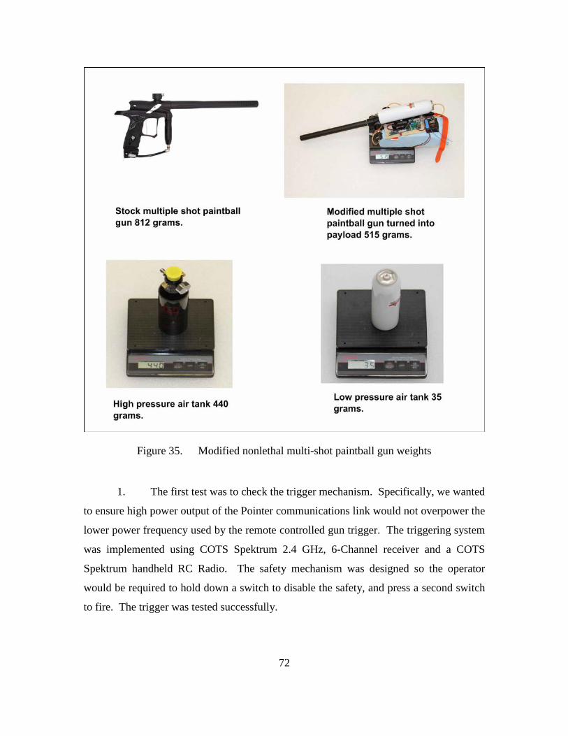
72
Figure 35. Modified nonlethal multi-shot paintball gun weights
1. The first test was to check the trigger mechanism. Specifically, we wanted
to ensure high power output of the Pointer communications link would not overpower the
lower power frequency used by the remote controlled gun trigger. The triggering system
was implemented using COTS Spektrum 2.4 GHz, 6-Channel receiver and a COTS
Spektrum handheld RC Radio. The safety mechanism was designed so the operator
would be required to hold down a switch to disable the safety, and press a second switch
to fire. The trigger was tested successfully.
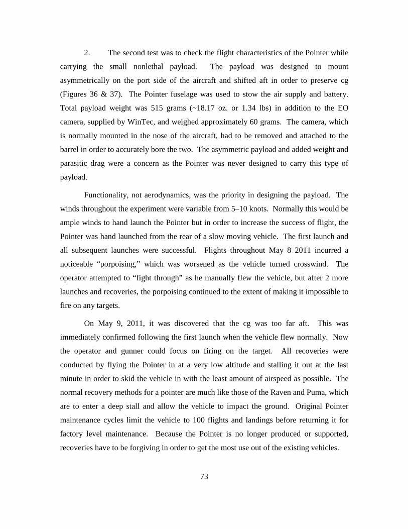
73
2. The second test was to check the flight characteristics of the Pointer while
carrying the small nonlethal payload. The payload was designed to mount
asymmetrically on the port side of the aircraft and shifted aft in order to preserve cg
(Figures 36 & 37). The Pointer fuselage was used to stow the air supply and battery.
Total payload weight was 515 grams (~18.17 oz. or 1.34 lbs) in addition to the EO
camera, supplied by WinTec, and weighed approximately 60 grams. The camera, which
is normally mounted in the nose of the aircraft, had to be removed and attached to the
barrel in order to accurately bore the two. The asymmetric payload and added weight and
parasitic drag were a concern as the Pointer was never designed to carry this type of
payload.
Functionality, not aerodynamics, was the priority in designing the payload. The
winds throughout the experiment were variable from 5–10 knots. Normally this would be
ample winds to hand launch the Pointer but in order to increase the success of flight, the
Pointer was hand launched from the rear of a slow moving vehicle. The first launch and
all subsequent launches were successful. Flights throughout May 8 2011 incurred a
noticeable “porpoising,” which was worsened as the vehicle turned crosswind. The
operator attempted to “fight through” as he manually flew the vehicle, but after 2 more
launches and recoveries, the porpoising continued to the extent of making it impossible to
fire on any targets.
On May 9, 2011, it was discovered that the cg was too far aft. This was
immediately confirmed following the first launch when the vehicle flew normally. Now
the operator and gunner could focus on firing on the target. All recoveries were
conducted by flying the Pointer in at a very low altitude and stalling it out at the last
minute in order to skid the vehicle in with the least amount of airspeed as possible. The
normal recovery methods for a pointer are much like those of the Raven and Puma, which
are to enter a deep stall and allow the vehicle to impact the ground. Original Pointer
maintenance cycles limit the vehicle to 100 flights and landings before returning it for
factory level maintenance. Because the Pointer is no longer produced or supported,
recoveries have to be forgiving in order to get the most use out of the existing vehicles.
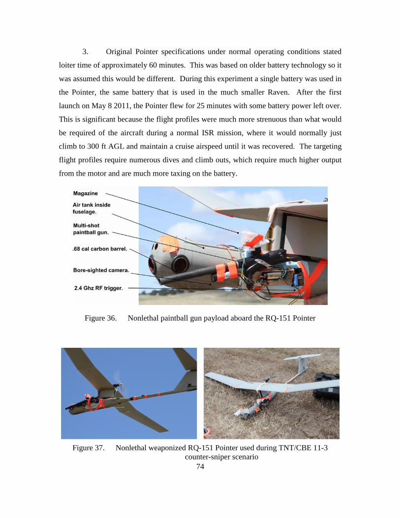
74
3. Original Pointer specifications under normal operating conditions stated
loiter time of approximately 60 minutes. This was based on older battery technology so it
was assumed this would be different. During this experiment a single battery was used in
the Pointer, the same battery that is used in the much smaller Raven. After the first
launch on May 8 2011, the Pointer flew for 25 minutes with some battery power left over.
This is significant because the flight profiles were much more strenuous than what would
be required of the aircraft during a normal ISR mission, where it would normally just
climb to 300 ft AGL and maintain a cruise airspeed until it was recovered. The targeting
flight profiles require numerous dives and climb outs, which require much higher output
from the motor and are much more taxing on the battery.
Figure 36. Nonlethal paintball gun payload aboard the RQ-151 Pointer
Figure 37. Nonlethal weaponized RQ-151 Pointer used during TNT/CBE 11-3
counter-sniper scenario
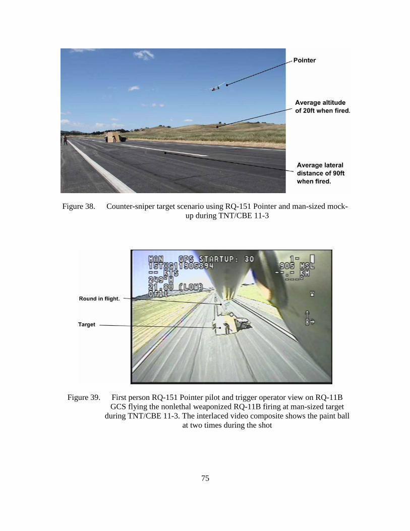
75
Figure 38. Counter-sniper target scenario using RQ-151 Pointer and man-sized mock-up during TNT/CBE 11-3
Figure 39. First person RQ-151 Pointer pilot and trigger operator view on RQ-11B GCS flying the nonlethal weaponized RQ-11B firing at man-sized target
during TNT/CBE 11-3. The interlaced video composite shows the paint ball at two times during the shot
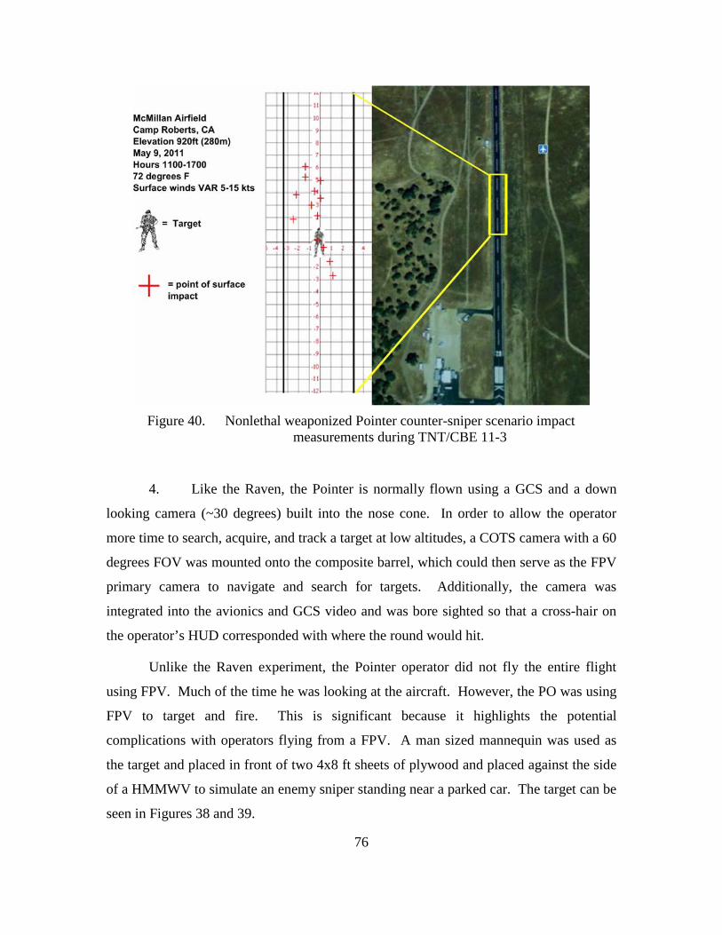
76
Figure 40. Nonlethal weaponized Pointer counter-sniper scenario impact
measurements during TNT/CBE 11-3
4. Like the Raven, the Pointer is normally flown using a GCS and a down
looking camera (~30 degrees) built into the nose cone. In order to allow the operator
more time to search, acquire, and track a target at low altitudes, a COTS camera with a 60
degrees FOV was mounted onto the composite barrel, which could then serve as the FPV
primary camera to navigate and search for targets. Additionally, the camera was
integrated into the avionics and GCS video and was bore sighted so that a cross-hair on
the operator’s HUD corresponded with where the round would hit.
Unlike the Raven experiment, the Pointer operator did not fly the entire flight
using FPV. Much of the time he was looking at the aircraft. However, the PO was using
FPV to target and fire. This is significant because it highlights the potential
complications with operators flying from a FPV. A man sized mannequin was used as
the target and placed in front of two 4x8 ft sheets of plywood and placed against the side
of a HMMWV to simulate an enemy sniper standing near a parked car. The target can be
seen in Figures 38 and 39.
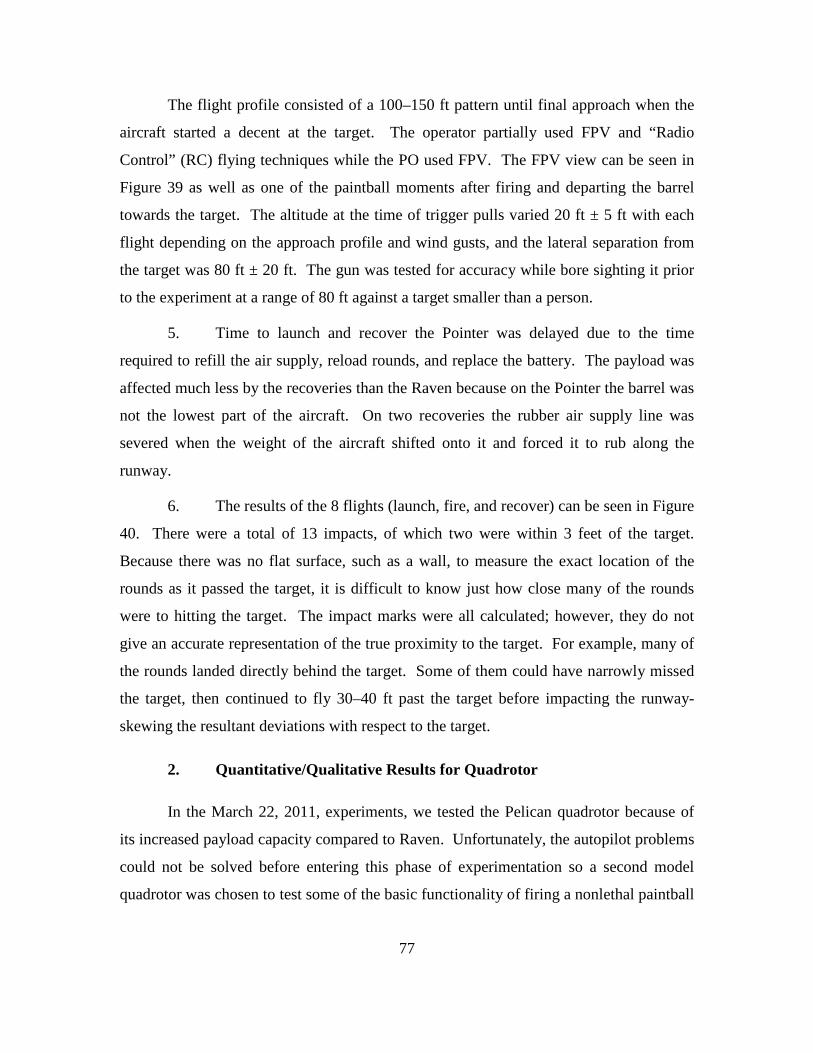
77
The flight profile consisted of a 100–150 ft pattern until final approach when the
aircraft started a decent at the target. The operator partially used FPV and “Radio
Control” (RC) flying techniques while the PO used FPV. The FPV view can be seen in
Figure 39 as well as one of the paintball moments after firing and departing the barrel
towards the target. The altitude at the time of trigger pulls varied 20 ft ± 5 ft with each
flight depending on the approach profile and wind gusts, and the lateral separation from
the target was 80 ft ± 20 ft. The gun was tested for accuracy while bore sighting it prior
to the experiment at a range of 80 ft against a target smaller than a person.
5. Time to launch and recover the Pointer was delayed due to the time
required to refill the air supply, reload rounds, and replace the battery. The payload was
affected much less by the recoveries than the Raven because on the Pointer the barrel was
not the lowest part of the aircraft. On two recoveries the rubber air supply line was
severed when the weight of the aircraft shifted onto it and forced it to rub along the
runway.
6. The results of the 8 flights (launch, fire, and recover) can be seen in Figure
40. There were a total of 13 impacts, of which two were within 3 feet of the target.
Because there was no flat surface, such as a wall, to measure the exact location of the
rounds as it passed the target, it is difficult to know just how close many of the rounds
were to hitting the target. The impact marks were all calculated; however, they do not
give an accurate representation of the true proximity to the target. For example, many of
the rounds landed directly behind the target. Some of them could have narrowly missed
the target, then continued to fly 30–40 ft past the target before impacting the runway-
skewing the resultant deviations with respect to the target.
2. Quantitative/Qualitative Results for Quadrotor
In the March 22, 2011, experiments, we tested the Pelican quadrotor because of
its increased payload capacity compared to Raven. Unfortunately, the autopilot problems
could not be solved before entering this phase of experimentation so a second model
quadrotor was chosen to test some of the basic functionality of firing a nonlethal paintball
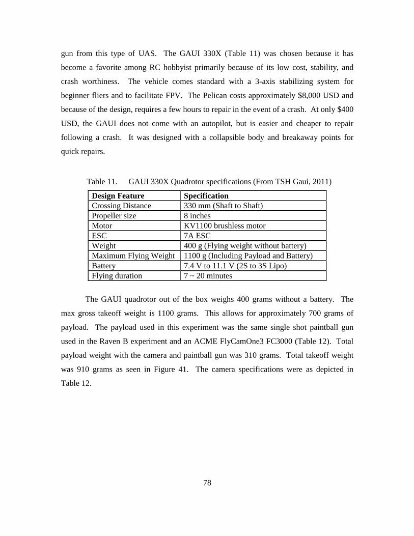
78
gun from this type of UAS. The GAUI 330X (Table 11) was chosen because it has
become a favorite among RC hobbyist primarily because of its low cost, stability, and
crash worthiness. The vehicle comes standard with a 3-axis stabilizing system for
beginner fliers and to facilitate FPV. The Pelican costs approximately $8,000 USD and
because of the design, requires a few hours to repair in the event of a crash. At only $400
USD, the GAUI does not come with an autopilot, but is easier and cheaper to repair
following a crash. It was designed with a collapsible body and breakaway points for
quick repairs.
Table 11. GAUI 330X Quadrotor specifications (From TSH Gaui, 2011)
Design Feature Specification Crossing Distance 330 mm (Shaft to Shaft) Propeller size 8 inches Motor KV1100 brushless motor ESC 7A ESC Weight 400 g (Flying weight without battery) Maximum Flying Weight 1100 g (Including Payload and Battery) Battery 7.4 V to 11.1 V (2S to 3S Lipo) Flying duration 7 ~ 20 minutes
The GAUI quadrotor out of the box weighs 400 grams without a battery. The
max gross takeoff weight is 1100 grams. This allows for approximately 700 grams of
payload. The payload used in this experiment was the same single shot paintball gun
used in the Raven B experiment and an ACME FlyCamOne3 FC3000 (Table 12). Total
payload weight with the camera and paintball gun was 310 grams. Total takeoff weight
was 910 grams as seen in Figure 41. The camera specifications were as depicted in
Table 12.
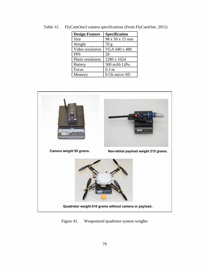
79
Table 12. FlyCamOne3 camera specifications (From FlyCamOne, 2011)
Design Feature Specification Size 98 x 50 x 15 mm Weight 70 g Video resolution VGA 640 x 480 FPS 28 Photo resolution 1280 x 1024 Battery 500 mAh LiPo. Focus 0.3 m Memory 8 Gb micro SD
Figure 41. Weaponized quadrotor system weights

80
1. The trigger servo was controlled through a spare servo controller on the
GAUI. While bore-sighting the paintball gun and camera prior to the experiments, we
discovered it was easier for the operator to also fire the gun instead of adding in a trigger
operator. This was accomplished through a two-position switch on the radio controller
that the operator could quickly flip when he wanted to fire.
2. Quadrotor aircraft are much more stable than other rotary aircraft of a
similar scale, but they generally require good deal of operator proficiency to fly
manually. This is especially true in windy conditions or gusty, unpredictable winds. The
wind conditions during the experiment were 5–15 knots with variable direction, which
slightly complicated the process. After arming the paintball gun, each flight profile
consisted of a vertical takeoff to an altitude of approximately 10 ft. The operator would
then maneuver the aircraft to a position 60–80 ft in front of the target and hold a hover at
around 10 ft altitude. After a few seconds of yaw and altitude adjustments to properly
aim the gun, the operator fired at the target. Figure 42 depicts the experiment scenario.
Figure 42. Counter-sniper target scenario using a quadrotor against a man-sized target during TNT/CBE 11-3
3. The endurance of the GAUI was approximately 10 minutes per battery
during this experiment. Since we had another 190 grams of unused payload, it was
possible to add a larger battery, which would have added some endurance.

81
4. The GAUI did not come with a GCS, autopilot software, or GPS
navigation therefore this part of the experiment was not applicable. There were no
noticeable communications problems between the video downlink and control links to the
flight controls or gun trigger at these ranges.
5. The capability to take off and land vertically from a fixed position can be a
definite advantage over the fixed wing UAS, which have to be hand launched from a
standing position or by running. This simplicity was evident during the experiments,
especially when it came to arming, and reloading the paintball gun. In a counter-sniper
scenario, this capability could prove useful in the ability to launch the UAS from a
moving vehicle or from small urban spaces without exposing the personnel. The Raven
UAS requires 100 ft of lateral clearance in order to ensure a successful takeoff. This will
differ slightly depending on wind speeds, direction, and pressure altitude. This lateral
distance requirement would be more for the Puma or Pointer, which are much heavier
vehicles. In a counter-sniper scenario, the operator would have to get to a secure clearing
or to the roof of a building in order to launch the fixed wing UAS. This would obviously
require more time than a quadrotor that could be launched from any position with vertical
clearance and a small amount of lateral clearance.

82
Figure 43. First person quadrotor pilot and trigger operator view while firing at man-sized target during TNT/CBE 11-3
6. Since the operator was flying manually, the accuracy of the bore sight
between the camera and gun could not be immediately discerned. After completion of
the experiments we reviewed the video and learned that the bore sight was surprisingly
good. Figure 43 depicts the FPV that would have been used by the PO. The square box
indicates the target area. In all instances where the operator fired, and the box was over
the target, the rounds impacted very close to the target. A total of 6 shots were fired, of
which 3 can be seen in Figure 44. One shot could be seen in the video review passing
within inches of the target’s head, and 2 shots impacted in unknown locations. We also
observed that the quadrotor gave the operator much more time on target, therefore
increasing the chance of hitting the target. During both the Raven and Pointer
experiments the trigger operator had only a fraction of a second to a second at most to get
a shot off and this was usually anticipating the target appearing on the cross hairs in the
video. This time was much greater when using the quadrotor at 2–4 seconds. The
tradeoff to this added time on target is that the quadrotor would, in theory, be more
susceptible to return fire by a sniper. However, there may be a benefit to using the UAS

83
as a decoy to draw fire. In the end, the priority would not necessarily be to kill the sniper,
but to gain his attention long enough to change the equation in favor of the victim which
could be through firing small arms in his general area.
Figure 44. Nonlethal weaponized quadrotor counter-sniper scenario paintball impact locations
3. CBE/TNT 11-3 Weaponized Pointer and Quadrotor Experiment Summary
The experiments were beneficial in identifying numerous data and factors
associated with using UAS in this role:
1. Heavier fixed wing SUAS such as the Pointer or Puma provide a much
more stable platform to fire; however, the time on target with all fixed wing SUAS was
extremely limited when compared to a rotary wing UAS. The vehicle should be limited
to 15 lbs and the total system should not weigh more than 60 lb.
2. Two key areas of future work are in both quadrotor technology and in
weapons to serve as the payload. Single shot small arms are not going to be worth the
effort because of the low probability of kill vs. the risk and time required to land and
reload. The triggering/firing mechanism would also have to be powered and integrated
into the current avionics and GCS hand held controller. Aircraft payload considerations
could be addressed through current technology small arms weapons, which use case-less,
84
electronically-fired small arms rounds. More area capability could come from a smaller,
lighter HE round, such as the FRAG-12 19 mm warhead rounds, which are made up of a
standard 3 inch, fin stabilized 12-gauge cartridge.
Recoil minimization will take some considerable work in the development of the
payload, particularly if used on a quadrotor or similar vehicle that fires from a hover.
The recoil was more noticeable when the gun was fired from the quadrotor. Since the
Pointer had velocity in the same direction as the projective, the recoil was insignificant.
On the quadrotor, the recoil did not adversely affect the first shot upon review of the
video it would have significantly affected a second shot if it was immediately fired. The
quadrotor would have required a small amount of time to stabilize onto the target before
firing a second shot.
F. SYSTEM DESIGN REQUIREMENTS
Using the data gained through the literature reviews and field experiments, we
will now summarize the conceptual design requirements for weaponizing a man-portable
UAS in support of counter-sniper operations. There are really two extremes to the
conceptual SUAS counter-sniper payload spectrum. On one extreme, there is an
expendable UAS that carries a warhead. The operator will not get this asset back once it
is employed; he has essentially used up his ISR UAS capability and his counter-sniper
capability from the air. He will need a second ISR capability if he plans to be able to see
over the next hill from the air.
On the other extreme, and the focus of this experiment, is to explore the feasibility
of arming an ISR asset with less killing power while preserving the original requirements
of the UAS. The experiments proved that from a functional aspect, these UAS could be
used to fire at a target. The effects gained are very hard to measure and will heavily
depend on the type of small arm used. A dead enemy sniper is the best possible outcome
in these systems, but what guarantee does the expendable UAS carrying a warhead bring
in achieving this goal, versus a distracted, displaced enemy sniper by a system on the
other extreme? When comparing the costs of each weaponized UAS explored in this
research, the Spike missile and Switchblade are orders or magnitude more than a small

85
arms payload. Collateral damage has to be considered and should be proportional to the
threat. Yes, precision guided bombs can be dropped if close air support is available and
the building with the sniper can be leveled to the ground, but then the building may have
to be rebuilt or the mission just supported the adversary’s information operations.
SUAS systems are designed to fulfill a wide variety of missions; however, these
systems can be broken down into a handful of major functional components as seen in
Figure 45. We will explore these components and how a payload of this type can be
integrated into this type of system.
Figure 45. UAV system—functional structure (From Austin, 2010)
1. Navigation
SUAS depend on navigation through the GPS. There are two basic services
associated with GPS that include the Standard Positioning Service (SPS) and the
Precision Positioning Service (PPS). The SPS is the basic service that provides timing
and position services to all users free of charge. SPS is provided through the L1 carrier
and includes the C/A code and a navigation data message. SPS provides a position
accuracy of 9 meters (95 percent) horizontally, 15 meters (95 percent) vertically and time
transfer accuracy to UTC within 40 nanoseconds (95 percent). PPS is available for

86
authorized users and is transmitted on the L1 and L2 frequencies (Figure 46). It is denied
to unauthorized users through encryption. PPS provides a higher accuracy rate than SPS,
which includes 2.7 meters (95 percent) horizontally, 4.9 meters vertically and time
transfer accuracy to UTC within 40 nanoseconds or better (95 percent). PPS can be
authorized for non-federal government civilian use on a case-by-case basis (US Naval
Oceanography Portal, 2011).
Figure 46. C/A and P(Y) code frequency differences (From Abidin, 2002)
Most SUAS within DoD operate using the P(Y) code in order to get the greatest
position resolution and also to gain the GPS anti-jam benefits of the P(Y) code. Because
SUAS are so dependent on GPS for their autonomy, their use in a GPS threatened
environment has to be taken into consideration. More importantly, in order to use an
SUAS to fire small arms at a sniper, the navigational system should be as precise as
possible. Current SUAS within DoD all use the P(Y) code because of the advantages of
increased navigational precision and anti-jam processing gains. Using the spread
spectrum spreading gain formula, we can see the differences between the C/A and P(Y)
code (Figure 47).

87
ssp
WGR
=
6
/1.023 10 20460 43
50C AHzG dB
bps×
= = =
610.23 10 204600 5350P
HzG dBbps×
= = =
Where Gp = Processing Gain
Wss = Spread Spectrum Bandwidth
R = Data Rate
Figure 47. Processing gain comparison between the C/A and P(Y) code (From Hui Hu, 2009)
The sniper problem is deeply connected to urban conflict, which presents more
opportunity for hidden GPS jammers. The global increase of available low cost GPS
jammers pose a reasonable risk to successful SUAS operations if the systems are not
designed to operate in a GPS denied environment. In order to spread the risk of losing
SUAS capabilities within a GPS denied environment, the system should include the
capability to navigate within more than one constellation, navigate within wireless mesh
networks, and increase operator proficiency in FPV and manual flight. Additionally, the
operator should be able to launch the vehicle without the requirement for a GPS starting
coordinate.
2. The Air Vehicle
The counter-sniper mission dictates many of the parameters for the design of the
air vehicle. The vehicle will be designed primarily for use with mounted or dismounted
company sized elements and below. This means the system must be lightweight and
highly portable. The vehicle should and have a quick assembly capability and easily
prepared for launch in a very short amount of time. Airspeed should be 0–50 kt for a
88
minimum of 45 minutes day or night with a payload of at least 1 lb (16 oz). The system
should not require more than two people to operate- one VO and one PO.
There are definite advantages and disadvantages to the type of vehicle used in this
role and because the mission depends on many factors, there is no single solution. An
urban launch position into an urban target area presents a short range profile and would
most likely favor a multi-rotor VTOL. More open area, or open launch areas into urban
targeting areas that require a long range (>3 km) would favor a fixed wing SUAS. If a
quadrotor could be made with endurance somewhere in the middle of current quadrotor
and fixed wing SUAS endurance, the quadrotor would bring significant advantages as a
single solution.
Since counter-sniper operations will generally be very close to the maximum
effective range of the sniper’s weapon, the UAS should be able to fly out to that
equivalent maximum range. The quadrotor must provide the operator with enough time
to search the area, target if the opportunity presents, have a “go-around” capability for a
few attempts, and return. All of this should be accomplished with very little workload to
the operator other than FPV manually “aiming” in the terminal area of the target. In
order to increase the time on target and overall chance of success of using a fixed wing
SUAS in this mission, the vehicle would have to either have the ability to enter a slight
dive profile or have enough lift to support a gimbaled weapon.
3. Launch and Recovery
The vehicle will be launched by hand standing in place, or by running start. The
vehicle should be capable of being pre-positioned either on a vehicle or ultra portable
launcher for quicker reaction times. Recovery methods should not require special
equipment and should be accurate within a small area such as a rooftop or courtyard.
4. Control Station
The ground control station should be rugged, simple, and intuitive to operate. The
video terminal should accommodate FPV for the VO and PO. The PO’s RVT should be
89
intuitive and contain built in safety mechanisms. Currently fielded GCS already meet
many of these requirements and could be used in support of these missions through some
small modifications.
5. Communications
The system uplink should support a minimum range of 5 km. The link should
also be encrypted, and accommodate multiple aircraft working within close proximity
without interference, and incorporate a control hand-over capability between
operators/controllers. The video signal and all signals required to operate the payload
should also be include in the link.
6. Interfaces
The mission/flight planning interface should be easy to learn and buttonology on
the GCS RVT should accommodate this. The vehicle will be capable of flying only ISR
missions with the weaponized payload; however, the payload should easily interface with
the SUAS with the need for additional time consuming steps. The video signal should
also interface with other systems in order to share information with adjacent or higher
units.
7. Payload
The payload will primarily consist of the weapon, however since the vehicle will
also be used in support of ISR missions the cameras will play a major part of the payload
design. Particularly, how the cameras will interface with the weapon while still serve
ISR missions with as much effectiveness or more than current SUAS.
a. The EO/IR Camera
Current SUAS use a 5 megapixel EO camera, which has a digital zoom
capability and is also digitally stabilized. The IR cameras have considerably less
90
resolution but this is made up for the advantages of capturing the thermal differential with
enough resolution to effectively identify a target during ISR missions and could also be
used in a counter-sniper role.
Figure 48. UAS camera look-down angle and vertical FOV
The field experiments highlighted the importance of the camera look-
down angle and FOV. If the FOV is too small, there are not enough visual cues for the
operator to effectively fly FPV but the target is easier to see. If the FOV is too large, it
makes FPV flying easier because there are more visual cues, but the target now takes up
fewer pixels and this makes acquiring it more difficult. Because fixed wing SUAS are
constantly moving forward, the vertical FOV is of most concern once the target is
acquired. In Figure 48 the look-down angle is represented by θ, and where the vertical
FOV is represented by α. Using a generic vertical FOV of 40 degrees, a look-down angle
of 30 degrees from the horizon, a constant airspeed of 32 km/h (8.9 m/s –slowest Raven
airspeed) and a constant altitude of 300 ft (91.44 m) AGL, a man-sized target would be
within the FOV for 67.5 seconds and within the target cross-hairs for .224 seconds. This
was reflected in our experiments, and the shots that impacted nearest the target were a
result of effectively leading the target to make the most of the small amount of time on
target.
Current fixed-wing SUAS have a look-down angle of approximately 30
degrees because it is the optimal angle for this mission. The extremely small TOT
presented above can only be increased by decreasing θ, which means there would have to

91
be at least two cameras onboard for optimal performance of both ISR and counter-sniper
missions, which would include a 30 degree down / forward looking camera, and a much
smaller θ of 10 degree down / forward looking camera for FPV and which would be bore-
sighted with the weapon. For ISR only missions, the FPV camera could be swapped for a
30 degree down / side looking camera.
b. The Weapon
Single shots small arms are not going to be worth the effort because of the
low probability of kill vs. the risk and time required. The triggering/firing mechanism
would have to be powered and integrated into the current avionics and ground station
hand held controller. Aircraft payload considerations could be addressed through current
technology small arms weapons that use case-less, electronically-fired small arms rounds.
The payload should be easily attached and removed from the vehicle for reloading or for
ISR only missions. The payload could consist of a “kit” made from a disposable,
extremely light weight (carbon fiber) material, which contains multiple rounds that could
be fired electronically. This would remove much of the weight associated with
conventional small arms weapons. Conventional mechanically fired payloads will bring
substantial weight to the system. Additionally, the electrically fired rounds may produce
less recoil if the design were to allow the round to accelerate over more time vs. the time
of a conventional small arms system. This may cost in muzzle velocity, but the reduced
recoil may be needed as to not destroy the UAS and the ranges needed to be accurate
would be much closer than normal small arms.
More lethal area capability could come from a smaller, lighter HE round,
such as the FRAG-12 19 mm warhead rounds, which are made up of a standard 3 inch,
fin stabilized 12-gauge cartridge. This type of round is much heavier and would certainly
restrict the system to only one available round per mission, but the area coverage would
be significantly increased.
92
8. Support Equipment and Maintenance
All required field repair and maintenance should be included with the system and
be included in the overall system weight. There should be enough spare parts to fly at
least 30 missions (1 per day for 1 month) without the need for resupply. The vehicle
design should be so that any repairs can be done by the operator in an austere location.
Major repairs should be supported at the nearest theatre service component wing level
maintenance facility.
9. Transportation
The SUAS should be back-packable between two people. The vehicle should be
limited to 15 lbs and the total system should not weigh more than 60 lb.

93
V. CONCLUSIONS AND RECOMMENDATIONS
A. SUMMARY AND CONCLUSION
The sniper threat will continue to pose problems for U.S. and Coalition forces
throughout OIF and OEF and into future contingencies as urban sprawl continues to grow
throughout the globe. Simultaneously, the information age has played a part in restricting
traditional counter-sniper tactics which produce unwanted collateral damage. This
research explored the design requirements of combining current UAS technology with
small arms technology in order to counter the sniper threat. The sniper equation is not
simple. Like any problem there are many variables which feed into the equation, and it
was discovered that weaponizing SUAS can contribute to changing the equation into a
less favorable outcome for the sniper.
Combat operations place the most amount of risk at the tactical level. Any
increase in organic ISR capability at this level helps to mitigate the risk. Furthermore,
any added capabilities to these ISR assets will also help abate risk. The adversary
currently views SUAS as harmless ISR assets but by weaponizing them–it could change
the way the adversary views SUAS all together.
These ‘all or nothing’ attitudes are each incorrect. High technology is not a silver bullet solution to insurgencies, but that doesn’t mean that technology doesn’t matter in these fights. In fact, far from proving the uselessness of advanced technology in modern warfare, Afghanistan and Iraq have for the first time proved the value of a technology that will truly revolutionize warfare—robotics. (Singer, 2011)
The cost of a small arms payload would be extremely attractive when compared
to other weaponized UAS. By incorporating a scalable payload which can be fitted onto
multiple vehicles, the overall system does not have to be designed from scratch in order
to support this one new capability. Most importantly, the ISR capability that the vehicles
were originally designed for is preserved. The ability to quickly and temporarily modify
existing UAS was is an important aspect of this research. It is less costly to expand the
capabilities of a commonly fielded system with modifications that produce expedient

94
results for the operators, than it is to make an entirely new system from scratch. Payloads
can be modified and adapted much easier than the air vehicles which is what would be
required of these systems.
By leveraging other systems, such as shot detection systems, an overall system of
systems can be produced against a common problem. Each system researched would be
much less effective without the other. However, combining systems which were not
originally designed to work together will undoubtedly entail some level of tradeoffs.
Tradeoffs are inherent to all engineering problems and this problem is no exception. The
currently fielded SUAS have a limited service life before depot level maintenance is
required. The maintenance cycle is measured in landings. Because they are usually deep
stalled, each landing takes a toll on the airframe. Adding additional weight to the vehicle
will induce premature wear and tear on the components. Based on this research, this
tradeoff would be acceptable when compared to the benefits gained in added capabilities
but the exact costs to the increased maintenance would have to be measured. This only
applies to fixed wing SUAS. The nature of VTOL operations, in theory, should decrease
the wear caused by landings and therefore mitigate the costs of combining the systems.
There is an increased skill level requirement to operate SUAS in this type of
mission but the operators quickly adapted. First person video (FPV) flying plays a bigger
role in these missions. It was also discovered that while current SUAS can be modified
with a small arms capability, there may be more suitable platforms within the SUAS
category depending on the need for VTOL or fixed wing vehicles and that the vehicle
will bring different capabilities such as to time on target and endurance.
Finally, while proving that SUAS can be weaponized against a sniper threat we
were not able to experiment with lethal weapons. Recommended future research includes
lethal weapon experimentation in order to explore the effects of recoil on the multiple
UAS vehicles while firing a single shot, versus multiple shots and to more accurately
measure how the enemy will react to small arms. While conducting experiments during
TNT and CBE, some unexpected research results came to light. The nonlethal weapon
95
system, which was designed to fire paintballs so that the impact marks could be easily
identifiable, was also identified as a potential delivery mechanism for tracking, tagging,
and locating agents (TTLI).
Many of the service components are tasked with the tagging, tracking, locating
and identifying persons of interests or high value targets. These missions are extremely
diverse and can be accomplished in countless ways depending on the target:
The Air Force wants a new kind of tracking tech in which a tiny drone surreptitiously ‘paints’ an individual with some kind of signal-emitting powder or liquid that allows the military to keep tabs on him or her. Or perhaps upload their coordinates to a hellfire missile. The AF has put out a call for proposals for such technology. Though they did not specify exactly what kind of drone might deliver the magic powder, or what the magic powder might be. (Dillow, 2011)
There is a significant amount of work to be done in how UAS can be weaponized to
deliver these taggants and to also deliver nonlethal and less than lethal payloads such as
chemical riot control rounds, deterrent rounds, or sting/stun grenades.

96
THIS PAGE INTENTIONALLY LEFT BLANK
97
LIST OF REFERENCES
Abidin, H. Z. (2002). Fundamentals of GPS signal and data. Manual of Geospatial Science and Technology (pp. 115–133). New York: Taylor and Francis.
AeroVironment, Inc. (March 2011a). Raven B overview. Retrieved from AeroVironment website http://www.avinc.com/downloads/Raven_Domestic_1210.pdf
AeroVironment, Inc. (March 2011b). Puma AE overview. Retrieved from AeroVironment website http://www.avinc.com/downloads/PumaAE_0910.pdf
AeroVironment, Inc. (March 2011c ). UAS advanced development: Wasp. Retrieved from AeroVironment website http://www.avinc.com/uas/adc/wasp/
AeroVironment, Inc. (March 2011d). UAS advanced development: Pointer FQM-151A. Retrieved from AeroVironment website http://www.avinc.com/uas/adc/pointer/
Ascending Technologies. (2010). AscTec Pelican. Retrieved from Ascending Technologies website http://www.asctec.de/asctec-pelican-3/
Austin, R. (2010). Unmanned aircraft systems: UAVs design, development, and deployment. West Sussex, UK: John Wiley and Sons.
Beidel, E. (2011) Army rushes to supply small drones to Afghanistan, but needs better trained operators. National Defense. Retrieved from http://www.nationaldefensemagazine.org/blog/lists/posts/post.aspx?ID=388
Blanchard, B. S. (2008). System engineering management, 4th Edition. (pp. 32–70) New Jersey: John Wiley and Sons.
Bloy, B. (2009). Optimizing the air-to-ground kill chain for time-sensitive targets. (Master’s thesis) Naval Postgraduate School: Monterey, CA. Retrieved from http://www.dtic.mil/cgi-bin/GetTRDoc?AD=ADA509155&Location=U2&doc=GetTRDoc.pdf
Carden, M. J. (May 2010). Army reaches 1 million unmanned flight hours. American Forces Press Service. Retrieved from http://www.defense.gov/news/newsarticle.aspx?id=59333
Chivers, C. J. (2010). Snipers imperil US-led forces in Afghanistan offensive. New York Times. Retrieved from http://www.nytimes.com/2010/02/18/world/asia/18marja.html
Clark, C. (2010). Sniper finder rushed to Afghanistan. DoD Buzz. Retrieved from http://www.dodbuzz.com/2010/04/02/sniper-finder-rushed-to-afghanistan/
98
Crane, D. (2006). Anti-sniper/sniper detection/gunfire detection systems at a glance. Defense Review. Retrieved from http://www.defensereview.com/anti-snipersniper-detectiongunfire-detection-systems-at-a-glance/
Curry, R. (2011). UAS vision: a global forum for the unmanned aircraft system community, Fukashima video Honeywell from T-Hawk. UAS Vision. Retrieved from http://www.uasvision.com/2011/05/09/fukushima-video-from-honeywells-t-hawk/
Defense Acquisition University. (2001). Systems engineering fundamentals. Fort Belvoir, VA: Defense Acquisition University Press. Retrieved from http://www.dau.mil/pubscats/PubsCats/SEFGuide%2001-01.pdf
Defense Industry Daily. (2011). Digital raven: hand-launched UAV goes binary. Defense Industry Daily. Retrieved from http://www.defenseindustrydaily.com/Digital-Raven-Up-to-666M-to-AeroVironment-for-UAV-Upgrades-06050/
Defense Update. (2010). Suicide micro-drones. Defense Update. Retrieved from http://defense-update.com/features/2010/december/31122010_suicide_uavs_5.html
Department of the Navy. (2001). Universal Navy Task List. (p. 262). Retrieved from http://www.uscg.mil/hq/cg5/cg513/docs/UNTL_ver_3.0_Jan_07.pdf
Dillow, C. (2011). The Air Force wants tiny drones that can squirt their prey with trackable sensor glue. POPSCI. Retrieved from http://www.popsci.com/technology/article/2011-04/air-force-wants-tiny-drones-can-paint-targets-trackable-sensor-goo#
Dorell, O. (2011). Aftershock could weaken damaged nuclear facility. USA Today. Retrieved from http://www.usatoday.com/news/world/2011-04-07-japan-earthquake_N.htm
Endsley, M. R. (1995). Toward a theory of situation awareness in dynamic systems. Human Factors. Lubbock Texas: Texas Tech University Retrieved from http://www.andrew.cmu.edu/course/95-855/95-855.class01.Endsley.pdf
Flightglobal. (2011). UAV directory: aircraft specification: Honeywell RQ-16 Tarantula Hawk. Flightglobal. Retrieved from http://www.flightglobal.com/directory/detail.aspx?aircraftCategory=UAV&manufacturerType=UAV&navigationItemId=374&aircraftId=7489&manufacturer=11907&keyword=&searchMode=Keyword&units=Imperial
FlyCamOne. (2011). FlyCamOne3 camera specifications. Retrieved from http://www.flycamone.co.uk/
99
Frank, R. (2009). Surveillance relies on unmanned flying machines: flight, payload technologies in pilotless MAVs drive their capabilities. DesignNews. Retrieved from http://www.designnews.com/article/278765-Surveillance_Relies_on_Unmanned_Flying_Vehicles.php
Golnar, M. (2010). Afghan journal: Afghan Taliban snipers the bigger enemy in Marjah. Reuters: Afghan Journal. Retrieved from http://blogs.reuters.com/afghanistan/2010/02/28/afghan-taliban-snipers-the-bigger-enemy-in-marjah
Hashin, A. S. (2006). Insurgency and counter-insurgency in Iraq. (p. 160). Ithaca, New York: Cornell University Press.
Headquarters United States Marine Corps. (1993). FMF 3-22-1: UAV Company Operations. Retrieved from http://www.marines.mil/news/publications/Documents/FMFM%203-22-1%20UAV%20Company%20Operations.pdf
Headquarters United States Army. (2006). FMI 3-04.155 Army unmanned aircraft system operations. Retrieved from http://www.fas.org/irp/doddir/army/fmi3-04-155.pdf
Headquarters United States Army. (2002). FMF-3-06.11 Combined arms operations in urban terrain. Retrieved from https://rdl.train.army.mil/soldierPortal/atia/adlsc/view/public/9629-1/fm/3-06.11/toc.htm
Hearing on Budget Request on Unmanned Aerial Vehicles (UAV) and Intelligence, Surveillance, and Reconnaissance (ISR) Capabilities: Committee on Armed Service, House of Representatives, Air and Land Forces Subcommittee. First session, April 19, 2007. Retrieved from http://www.fas.org/irp/congress/2007_hr/uav.pdf
Hoff, S. (2009). Mini-UAS for counter-piracy operations: NATO counter-piracy workshop. Retrieved from http://www.nato.int/structur/AC/141/pdf/S-B/AeroVironment.pdf
Hornyak, T. (2011). US Troops Getting Wearable Gunshot Detectors. CNET News. Retrieved from http://news.cnet.com/8301-17938_105-20045440-1.html
Hui Hu, N. W. (2009). A study of GPS jamming and anti-jamming. Power Electronics and Intelligent Transportation System (PEITS), 2009 2nd International Conference on.
Hsu, J. (2007). Tracing a bullet back to its gun. scienceline. Retrieved from http://scienceline.org/2007/01/tech-hsu-guns/
100
Isherwood, M., & Garrison, M. (2008). The new generation of unmanned aircraft systems and the Marine Corps. Marine Corps Gazette. (pp. 13–15). Retrieved from http://www.marinecorpsgazette-digital.com/marinecorpsgazette/200802/?pg=19#pg15
Jamshidi, M. (2008). System of systems engineering – new challenges for the 21st century. IEEE A&E Systems Magazine. (pp. 4–19).
Jervis, R. (2006). More troops means more targets for snipers in Iraq. USA Today. Retrieved from http://www.usatoday.com/news/world/iraq/2006-10-24-sniper-targets_x.htm
Keegan, J. (2005). The Iraq war. New York: Random House.
Lamb, T. (2006). Small unmanned aerial system (SUAS) flight and mission control support systems (FMCSS) design. Master’s thesis, Naval Postgraduate School: Monterey, CA. Retrieved from http://www.dtic.mil/cgi-bin/GetTRDoc?AD=ADA457224&Location=U2&doc=GetTRDoc.pdf
Mathews, W. (2010). Smaller, lighter, cheaper new missiles are “absolutely ideal” for irregular warfare. Defense News. Retrieved from http://www.defensenews.com/story.php?i=4649372
Marine Corps Systems Command (MARCORSYSCOM). (2011). Unmanned aircraft systems. (2011). With permission.
Mawn, A. & Tokumaru, P. (2006). The Pathfinder Raven small unmanned aerial vehicle. Retrieved from http://www.dtic.mil/cgi-bin/GetTRDoc?Location=U2&doc=GetTRDoc.pdf&AD=ADA432526
McKeegan, N. (2008). BATMAV system with AeroVironment’s WASP III micro air vehicle achieves full rate production. Gizmag. Retrieved from http://www.gizmag.com/aerovironment-wasp-iii-micro-air-vehicle/8605/
Mortimer, G. (2010). Route clearance in Iraq goes high-tech RQ-16A Tarantula Hawk. sUAS News. Retrieved from http://www.suasnews.com/2010/12/3220/route-clearance-in-iraq-goes-high-tech-rq-16a-tarantula-hawk/
Naval Air Warfare Center Weapons Division. (2010). U.S. NAWCWD Gets Closer to Putting Mini-Weapons On Small UAVs. Retrieved from http://www.defpro.com/news/details/20211/?SID=4dd3e5aa5bed572e01e1ba6c19d4cb47
O’Connor, S. (2007). New UAV Raven B Increases Airmen’s Vision. Air Force Times, November 25, 2007. Retrieved from http://www.airforcetimes.com/news/2007/11/airforce_ravenb_071125w/

101
Office of Naval Research. (2011). Gunslinger Package for Advanced Convoy Security. Retrieved from http://www.onr.navy.mil/en/Media-Center/Fact-Sheets/Gunslinger-Convoy.aspx
Orr, B. (2010). Predator Drone Shift from Battlefield to Border: Homeland Security patrols Mexican, Canadian Borders, Caribbean with High-Tech Aircraft Known for Hunting Terrorists. Retrieved from http://www.cbsnews.com/stories/2010/11/09/eveningnews/main7038641.shtml
Parsh, A. (2007a). Directory of military rockets and missiles: Appendix 2, modern UAVs – RQ-14 Raven. Retrieved from http://www.designation-systems.net/dusrm/app2/q-14.html
Parsh, A. (2007b). Directory of military rockets and missiles: Appendix 2, modern UAVs—RQ-16. Retrieved from http://www.designation-systems.net/dusrm/app2/q-16.html
Richardson, K. (March 2011). Send out the ravens, save soldiers. Retrieved from http://www.army.mil/-news/2011/03/16/53328-send-out-ravens-save-soldiers/
Singer, P. (2009), Wired for war: The robotics revolution and conflict in the twenty-first century. London: The Penguin Press.
Singer, P. (2011). Military robots and the laws of war. Brookings. Retrieved from http://www.brookings.edu/articles/2009/winter_robots_singer.aspx
Smith, M. (April 2011). Flying drone peers into Japan’s damaged reactors. CNN. Retrieved from http://www.cnn.com/2011/WORLD/asiapcf/04/10/japan.nuclear.reactors/index.html?hpt=T2
TSH Gaui. (2011). 330X-S quad-flyer. Retrieved from http://www.gaui.com.tw/html/shopping_view.asp?sn=1028
U. S. Army UAS Center for Excellence. (2010). U.S. Army unmanned aircraft systems roadmap 2010-2035. Retrieved from http://www-rucker.army.mil/usaace/uas/US%20Army%20UAS%20RoadMap%202010%202035.pdf
U.S. Department of Defense. (2007). Coalition and Iraqi forces capture terrorist suspects. Retrieved from http://www.defense.gov/news/newsarticle.aspx?id=47357
U.S. Air Force Special Operations Command (AFSOC). (2009). Wasp III micro remotely piloted aircraft fact sheet. Retrieved from http://www.afsoc.af.mil/library/factsheets/factsheet.asp?id=9114

102
U.S. Naval Oceanography Portal. (2011). GPS Info: USNO NAVSTAR global positioning system information. Retrieved from http://www.usno.navy.mil/USNO/time/gps/gps-info#cap
Under Secretary of Defense (AT&L). (2007). Unmanned systems roadmap 2007–2032. (p. 35). Retrieved from http://www.fas.org/irp/program/collect/usroadmap2007.pdf
Wah, K. K.. (n.d.) Application of airpower in urban warfare. (p. 15). Retrieved from http://www.mindef.gov.sg/content/imindef/publications/pointer/supplements/LDAC/_jcr_content/imindefPars/0006/file.res/ApplicationOfAirpower.pdf
Watson, J. (2011). Marines define future role amid budget cuts. Deseret News. Retrieved from http://www.deseretnews.com/article/700109499/Marines-define-future-role-amid-budget-cuts.html
Work, R. (2010). Post-Afghanistan Marine Corps. Marine Corps Gazette. (p. 106). Retrieved from http://www.mca-marines.org/gazette/article/post-afghanistan-marine-corps

103
INITIAL DISTRIBUTION LIST
1. Defense Technical Information Center Ft. Belvoir, Virginia
2. Dudley Knox Library Naval Postgraduate School Monterey, California
3. Marine Corps Representative Naval Postgraduate School Monterey, California 4. Director, Training and Education, MCCDC, Code C46 Quantico, Virginia 5. Director, Marine Corps Research Center, MCCDC, Code C40RC Quantico, Virginia 6. Marine Corps Tactical Systems Support Activity (Attn: Operations Officer) Camp Pendleton, California 8. Chairman
Code IS Department of Information Sciences Naval Postgraduate School Monterey, California
9. Dr. Raymond R. Buettner
Associate Professor Department of Information Sciences Naval Postgraduate School Monterey, California
10. Dr. Kevin D. Jones
Research Associate Professor Department of Mechanical and Aerospace Engineering Naval Postgraduate School Monterey, California