Design Qualification Test Report MMS/TMM MMS-140-02-S-DV-A ...
71
Project Number: Design Qualification Test Report Tracking Code: 154341_Report_Rev_2 Requested by: Mark Shireman Date: 12/7/2011 Product Rev: 0 Part #: MMS-140-02-S-DV-A/TMM-140-01-S-D-SM-A Lot #: N/A Tech: Tony Wagoner Eng: Eric Mings Part description: MMS/TMM Qty to test: 45 Test Start: 7/15/2011 Test Completed: 8/15/2011 Page 1 of 71 Design Qualification Test Report MMS/TMM MMS-140-02-S-DV-A/TMM-140-01-S-D-SM-A
Transcript of Design Qualification Test Report MMS/TMM MMS-140-02-S-DV-A ...

Project Number: Design Qualification Test Report Tracking Code: 154341_Report_Rev_2
Requested by: Mark Shireman Date: 12/7/2011 Product Rev: 0
Part #: MMS-140-02-S-DV-A/TMM-140-01-S-D-SM-A Lot #: N/A Tech: Tony Wagoner Eng: Eric Mings
Part description: MMS/TMM Qty to test: 45
Test Start: 7/15/2011 Test Completed: 8/15/2011
Page 1 of 71
Design Qualification Test Report
MMS/TMM
MMS-140-02-S-DV-A/TMM-140-01-S-D-SM-A

Tracking Code: 154341_Report_Rev_1 Part #: MMS-140-02-S-DV-A/TMM-140-01-S-D-SM-A Part description: MMS/TMM
Page 2 of 71
CERTIFICATION All instruments and measuring equipment were calibrated to National Institute for Standards and Technology (NIST) traceable standards according to IS0 10012-l and ANSI/NCSL 2540-1, as applicable. All contents contained herein are the property of Samtec. No portion of this report, in part or in full shall be reproduced without prior written approval of Samtec. SCOPE To perform the following tests: Design Qualification Test, Please see test plan. APPLICABLE DOCUMENTS Standards: EIA Publication 364 TEST SAMPLES AND PREPARATION
1) All materials were manufactured in accordance with the applicable product specification. 2) All test samples were identified and encoded to maintain traceability throughout the test sequences. 3) After soldering, the parts to be used for LLCR and DWV/IR testing were cleaned according to TLWI-0001. 4) Either an automated cleaning procedure or an ultrasonic cleaning procedure may be used. 5) The automated procedure is used with aqueous compatible soldering materials. 6) Parts not intended for testing LLCR and DWV/IR are visually inspected and cleaned if necessary. 7) Any additional preparation will be noted in the individual test sequences. 8) Solder Information: Lead free 9) Re-Flow Time/Temp: See accompanying profile.

Tracking Code: 154341_Report_Rev_1 Part #: MMS-140-02-S-DV-A/TMM-140-01-S-D-SM-A Part description: MMS/TMM
Page 3 of 71
TYPICAL OVEN PROFILE (Soldering Parts to Test Boards)

Tracking Code: 154341_Report_Rev_1 Part #: MMS-140-02-S-DV-A/TMM-140-01-S-D-SM-A Part description: MMS/TMM
Page 4 of 71
FLOWCHARTS
Gas Tight
TEST GROUP A1STEP 192 Points
01 LLCR-102 Gas Tight03 LLCR-2
Gas Tight = EIA-364-36A
LLCR = EIA-364-23, LLCR
20 mV Max, 100 mA Max
Use Keithley 580 or 3706 in 4 wire dry circuit mode Thermal Aging
TEST GROUP A1STEP 8 Boards
Thermal Aging (Mated)01 Forces - Mating / Unmating02 LLCR-1
03 Thermal Aging(Mated and Undisturbed)
04 LLCR-205 Forces - Mating / Unmating
Thermal Aging = EIA-364-17, Test Condition 4 (105°C)
Time Condition 'B' (250 Hours)
Mating / Unmating Forces = EIA-364-13
LLCR = EIA-364-23, LLCR
20 mV Max, 100 mA Max
Use Keithley 580 or 3706 in 4 wire dry circuit mode

Tracking Code: 154341_Report_Rev_1 Part #: MMS-140-02-S-DV-A/TMM-140-01-S-D-SM-A Part description: MMS/TMM
Page 5 of 71
FLOWCHARTS Continued
Durability/Mating/Unmating/Gaps
TEST GROUP B1 GROUP B2 GROUP B3
STEP 8 Boards(largest position submitted)
8 Boards(middle position submitted)
8 Boards(smallest position submitted)
01 Contact Gaps Contact Gaps Contact Gaps02 LLCR-1 Forces - Mating / Unmating Forces - Mating / Unmating03 Forces - Mating / Unmating 25 Cycles 25 Cycles04 25 Cycles Forces - Mating / Unmating Forces - Mating / Unmating05 Forces - Mating / Unmating 25 Cycles (50 Total) 25 Cycles (50 Total)06 25 Cycles (50 Total) Forces - Mating / Unmating Forces - Mating / Unmating07 Forces - Mating / Unmating 25 Cycles (75 Total) 25 Cycles (75 Total)08 25 Cycles (75 Total) Forces - Mating / Unmating Forces - Mating / Unmating09 Forces - Mating / Unmating 25 Cycles (100 Total) 25 Cycles (100 Total)10 25 Cycles (100 Total) Forces - Mating / Unmating Forces - Mating / Unmating11 Forces - Mating / Unmating12 Clean w/Compressed Air13 Contact Gaps14 LLCR-2
15 Thermal Shock(Mated and Undisturbed)
16 LLCR-3
17 Cyclic Humidity(Mated and Undisturbed)
18 LLCR-419 Forces - Mating / Unmating
Thermal Shock = EIA-364-32, Table II, Test Condition I:
-55oC to +85oC 1/2 hour dwell, 100 cycles
Humidity = EIA-364-31, Test Condition B (240 Hours)
and Method III (+25°C to +65°C @ 90% RH to 98% RH)
ambient pre-condition and delete steps 7a and 7b
Mating / Unmating Forces = EIA-364-13
Contact Gaps / Height - No standard method. Usually measured optically.
Gaps to be taken on a minimum of 20% of each part tested
LLCR = EIA-364-23, LLCR
20 mV Max, 100 mA Max
Use Keithley 580 or 3706 in 4 wire dry circuit mode

Tracking Code: 154341_Report_Rev_1 Part #: MMS-140-02-S-DV-A/TMM-140-01-S-D-SM-A Part description: MMS/TMM
Page 6 of 71
FLOWCHARTS Continued IR & DWV TEST GROUP A1 GROUP A2 GROUP A3 GROUP B1
STEP 2 Mated Sets 2 Unmated of Part #Being Tested
2 Unmated of Mating Part # 2 Mated Sets
Break Down Pin-to-Pin Break Down Pin-to-Pin Break Down Pin-to-Pin Pin-to-Pin
01 DW V/Break Down Voltage DWV/Break Down Voltage DWV/Break Down VoltageIR & DWV at test voltage
(on both mated sets and on eachconnector unmated)
02 Thermal Shock(Mated and Undisturbed)
03IR & DWV at test voltage
(on both mated sets and on eachconnector unmated)
04 Cyclic Humidity(Mated and Undisturbed)
05IR & DWV at test voltage
(on both mated sets and on eachconnector unmated)
TEST GROUP C1 GROUP C2 GROUP C3 GROUP D1
STEP 2 Mated Sets 2 Unmatedof Part #Being Tested
2 Unmated of Mating Part # 2 Mated Sets
Break Down Row-to-Row Break Down Row-to-Row Break Down Row-to-Row Row-to-Row
01 DW V/Break Down Voltage DWV/Break Down Voltage DWV/Break Down VoltageIR & DWV at test voltage
(on both mated sets and on eachconnector unmated)
02 Thermal Shock(Mated and Undisturbed)
03IR & DWV at test voltage
(on both mated sets and on eachconnector unmated)
04 Cyclic Humidity(Mated and Undisturbed)
05IR & DWV at test voltage
(on both mated sets and on eachconnector unmated)
Thermal Shock = EIA-364-32, Table II, Test Condition I:-55oC to +85oC 1/2 hour dwell, 100 cycles
Humidity = EIA-364-31, Test Condition B (240 Hours) and Method III (+25°C to +65°C @ 90% RH to 98% RH)ambient pre-condition and delete steps 7a and 7b
IR = EIA-364-21DWV = EIA-364-20, Test Condition 1
DWV test voltage is equal to 75% of the lowest break down voltage from Groups A1, A2 or A3DWV on Group B1 to be performed at Test Voltage

Tracking Code: 154341_Report_Rev_1 Part #: MMS-140-02-S-DV-A/TMM-140-01-S-D-SM-A Part description: MMS/TMM
Page 7 of 71
FLOWCHARTS Continued
Normal Force
TEST GROUP A1 GROUP A2
STEP Individual Contacts(8-10 min)
Individual Contacts(8-10 min)
01 Contact Gaps Contact Gaps
02 Setup Approved Thermal Aging(Mated and Undisturbed)
03Normal Force
(in the body and soldered on PCBunless otherwise specified)
Contact Gaps
04 Setup Approved
05Normal Force
(in the body and soldered on PCBunless otherwise specif ied)
Thermal Aging = EIA-364-17, Test Condition 4 (105°C)
Time Condition 'B' (250 Hours)
Normal Force = EIA-364-04
(Perpendicular) Displacement Force = 12.7 mm/min ± 6 mm/min
Spec is 50 N @ 1 mm displacement
Contact Gaps / Height - No standard method. Usually measured optically
Current Carrying Capacity - Double Row
TEST GROUP B1 GROUP B2 GROUP B3STEP 3 Mated Assemblies 3 Mated Assemblies 3 Mated Assemblies
2 Contacts Powered 4 Contacts Powered 6 Contacts Powered01 CCC CCC CCC
TEST GROUP B4 GROUP B5
STEP 3 Mated Assemblies 3 Mated Assemblies8 Contacts Powered All Contacts Powered
01 CCC CCC(TIN PLATING) - Tabulate calculated current at RT, 65°C, 75°C and 95°C
after derating 20% and based on 105°C(GOLD PLATING) - Tabulate calculated current at RT, 85°C, 95°C and 115°C
after derating 20% and based on 125°CCCC, Temp rise = EIA-364-70

Tracking Code: 154341_Report_Rev_1 Part #: MMS-140-02-S-DV-A/TMM-140-01-S-D-SM-A Part description: MMS/TMM
Page 8 of 71
FLOWCHARTS Continued Mechanical Shock / Vibration / LLCR
TEST GROUP A1STEP 192 Points
01 LLCR-102 Shock03 Vibration04 LLCR-2
Mechanical Shock = EIA 364-27 Half Sine,
100 g's, 6 milliSeconds (Condition "C") each axis
Vibration = EIA 364-28, Random Vibration
7.56 g RMS, Condition VB --- 2 hours/axis
LLCR = EIA-364-23, LLCR
20 mV Max, 100 mA MaxUse Keithley 580 or 3706 in 4 wire dry circuit mode
Shock / Vibration / nanoSecond Event Detection
TEST GROUP A1STEP 60 Points
01 Event Detection,Shock
02 Event Detection,Vibration
Mechanical Shock = EIA 364-27 Half Sine,
100 g's, 6 milliSeconds (Condition "C") each axis
Vibration = EIA 364-28, Random Vibration
7.56 g RMS, Condition VB --- 2 hours/axis
Event detection requirement during Shock / Vibration is 50 nanoseconds minimum

Tracking Code: 154341_Report_Rev_1 Part #: MMS-140-02-S-DV-A/TMM-140-01-S-D-SM-A Part description: MMS/TMM
Page 9 of 71
FLOWCHARTS Continued Extended Life
TEST GROUP B1 GROUP C1STEP 192 Points 192 Points
250 Cycles 500 Cycles
01 * Plating ThicknessVerif ication
* Plating ThicknessVerif ication
02 LLCR-1 LLCR-103 250 Cycles 500 Cycles04 Clean Mating Interface Clean Mating Interface05 LLCR-2 LLCR-2
06 Thermal Shock(Mated and undisturbed)
Thermal Shock(Mated and undisturbed)
07 LLCR-3 LLCR-3
08 Cyclic Humidity(Mated and undisturbed)
Cyclic Humidity(Mated and undisturbed)
09 LLCR-4 LLCR-410 *** Photos of Contact Area *** Photos of Contact Area
Thermal Shock = EIA-364-32, Table II, Test Condition I:
-55oC to +85oC 1/2 hour dwell, 100 cycles
Humidity =EIA-364-31, Test Condition 'B' (240 Hours)
and Method III (+25°C to +65°C @ 90% RH to 98% RH)
ambient pre-condition and delete steps 7a and 7b
LLCR = EIA-364-23, LLCR
20 mV Max, 100 mA Max
Use Keithley 580 or 3706 in 4 wire dry circuit mode
* Measure, verify, and document plating thickness on both male and female (one group only)
** Plating thickness to be measured on loose pins used during assembly. Pins to be provided by requestor.
*** Save 2-3 photos of contact area in project folder for each group

Tracking Code: 154341_Report_Rev_1 Part #: MMS-140-02-S-DV-A/TMM-140-01-S-D-SM-A Part description: MMS/TMM
Page 10 of 71
ATTRIBUTE DEFINITIONS The following is a brief, simplified description of attributes.
THERMAL SHOCK: 1) EIA-364-32, Thermal Shock (Temperature Cycling) Test Procedure for Electrical Connectors. 2) Test Condition 1: -55°C to +85°C 3) Test Time: ½ hour dwell at each temperature extreme 4) Number of Cycles: 100 5) All test samples are pre-conditioned at ambient. 6) All test samples are exposed to environmental stressing in the mated condition.
THERMAL:
• EIA-364-17, Temperature Life with or without Electrical Load Test Procedure for Electrical Connectors. • Test Condition 4 at 105° C. • Test Time Condition B for 250 hours. • All test samples are pre-conditioned at ambient. • All test samples are exposed to environmental stressing in the mated condition.
HUMIDITY:
1) Reference document: EIA-364-31, Humidity Test Procedure for Electrical Connectors. 2) Test Condition B, 240 Hours. 3) Method III, +25° C to + 65° C, 90% to 98% Relative Humidity excluding sub-cycles 7a and 7b. 4) All samples are pre-conditioned at ambient. 5) All test samples are exposed to environmental stressing in the mated condition.
MECHANICAL SHOCK (Specified Pulse):
1) Reference document: EIA-364-27, Mechanical Shock Test Procedure for Electrical Connectors 2) Test Condition C 3) Peak Value: 100 G 4) Duration: 6 Milliseconds 5) Wave Form: Half Sine 6) Velocity: 12.3 ft/s 7) Number of Shocks: 3 Shocks / Direction, 3 Axis (18 Total)
VIBRATION:
1) Reference document: EIA-364-28, Vibration Test Procedure for Electrical Connectors 2) Test Condition V, Letter B 3) Power Spectral Density: 0.04 G² / Hz 4) G ‘RMS’: 7.56 5) Frequency: 50 to 2000 Hz 6) Duration: 2.0 Hours per axis (3 axis total)
NANOSECOND-EVENT DETECTION:
1) Reference document: EIA-364-87, Nanosecond-Event Detection for Electrical Connectors 2) Prior to test, the samples were characterized to assure the low nanosecond event being monitored will trigger
the detector. 3) After characterization it was determined the test samples could be monitored for 50 nanosecond events

Tracking Code: 154341_Report_Rev_1 Part #: MMS-140-02-S-DV-A/TMM-140-01-S-D-SM-A Part description: MMS/TMM
Page 11 of 71
ATTRIBUTE DEFINITIONS The following is a brief, simplified description of attributes.
CONTACT GAPS: 1) Gaps above the surrounding plastic surface were measured before and after stressing the contacts (e.g.
thermal aging, mechanical cycling, etc.). 2) Typically, all contacts on the connector are measured.
MATING/UNMATING:
1) Reference document: EIA-364-13, Mating and Unmating Forces Test Procedure for Electrical Connectors. 2) The full insertion position was to within 0.003” to 0.004” of the plug bottoming out in the receptacle to
prevent damage to the system under test. 3) One of the mating parts is secured to a floating X-Y table to prevent damage during cycling.
NORMAL FORCE (FOR CONTACTS TESTED IN THE HOUSING):
1) Reference document: EIA-364-04, Normal Force Test Procedure for Electrical Connectors. 2) The contacts shall be tested in the connector housing. 3) If necessary, a “window” shall be made in the connector body to allow a probe to engage and deflect the
contact at the same attitude and distance (plus 0.05 mm [0.002”]) as would occur in actual use. 4) The connector housing shall be placed in a holding fixture that does not interfere with or otherwise influence
the contact force or deflection. 5) Said holding fixture shall be mounted on a floating, adjustable, X-Y table on the base of the Dillon TC2,
computer controlled test stand with a deflection measurement system accuracy of 5.0 µm (0.0002”). 6) The nominal deflection rate shall be 5 mm (0.2”)/minute. 7) Unless otherwise noted a minimum of five contacts shall be tested. 8) The force/deflection characteristic to load and unload each contact shall be repeated five times. 9) The system shall utilize the TC2 software in order to acquire and record the test data. 10) The permanent set of each contact shall be measured within the TC2 software. 11) The acquired data shall be graphed with the deflection data on the X-axis and the force data on the Y-axis
and a print out will be stored with the Tracking Code paperwork. INSULATION RESISTANCE (IR):
To determine the resistance of insulation materials to leakage of current through or on the surface of these materials when a DC potential is applied.
1) PROCEDURE: a. Reference document: EIA-364-21, Insulation Resistance Test Procedure for Electrical Connectors. b. Test Conditions:
i. Between Adjacent Contacts or Signal-to-Ground ii. Electrification Time 2.0 minutes iii. Test Voltage (500 VDC) corresponds to calibration settings for measuring resistances.
2) MEASUREMENTS: 3) When the specified test voltage is applied (VDC), the insulation resistance shall not be less than 5000
megohms.
Tracking Code: 154341_Report_Rev_1 Part #: MMS-140-02-S-DV-A/TMM-140-01-S-D-SM-A Part description: MMS/TMM
Page 12 of 71
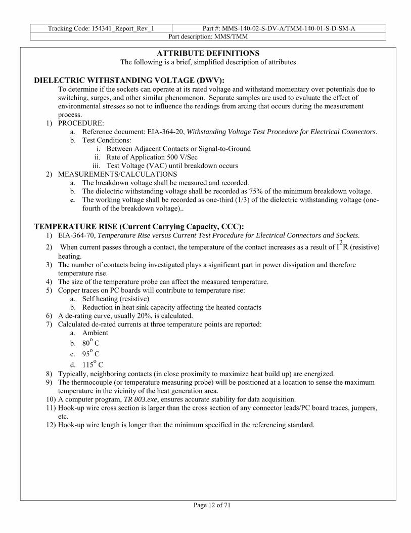
ATTRIBUTE DEFINITIONS The following is a brief, simplified description of attributes
DIELECTRIC WITHSTANDING VOLTAGE (DWV):
To determine if the sockets can operate at its rated voltage and withstand momentary over potentials due to switching, surges, and other similar phenomenon. Separate samples are used to evaluate the effect of environmental stresses so not to influence the readings from arcing that occurs during the measurement process.
1) PROCEDURE: a. Reference document: EIA-364-20, Withstanding Voltage Test Procedure for Electrical Connectors. b. Test Conditions:
i. Between Adjacent Contacts or Signal-to-Ground ii. Rate of Application 500 V/Sec
iii. Test Voltage (VAC) until breakdown occurs 2) MEASUREMENTS/CALCULATIONS
a. The breakdown voltage shall be measured and recorded. b. The dielectric withstanding voltage shall be recorded as 75% of the minimum breakdown voltage. c. The working voltage shall be recorded as one-third (1/3) of the dielectric withstanding voltage (one-
fourth of the breakdown voltage).. TEMPERATURE RISE (Current Carrying Capacity, CCC):
1) EIA-364-70, Temperature Rise versus Current Test Procedure for Electrical Connectors and Sockets. 2) When current passes through a contact, the temperature of the contact increases as a result of I2R (resistive)
heating. 3) The number of contacts being investigated plays a significant part in power dissipation and therefore
temperature rise. 4) The size of the temperature probe can affect the measured temperature. 5) Copper traces on PC boards will contribute to temperature rise:
a. Self heating (resistive) b. Reduction in heat sink capacity affecting the heated contacts
6) A de-rating curve, usually 20%, is calculated. 7) Calculated de-rated currents at three temperature points are reported:
a. Ambient b. 80о C c. 95о C d. 115о C
8) Typically, neighboring contacts (in close proximity to maximize heat build up) are energized. 9) The thermocouple (or temperature measuring probe) will be positioned at a location to sense the maximum
temperature in the vicinity of the heat generation area. 10) A computer program, TR 803.exe, ensures accurate stability for data acquisition. 11) Hook-up wire cross section is larger than the cross section of any connector leads/PC board traces, jumpers,
etc. 12) Hook-up wire length is longer than the minimum specified in the referencing standard.

Tracking Code: 154341_Report_Rev_1 Part #: MMS-140-02-S-DV-A/TMM-140-01-S-D-SM-A Part description: MMS/TMM
Page 13 of 71
ATTRIBUTE DEFINITIONS The following is a brief, simplified description of attributes.
LLCR: 1) EIA-364-23, Low Level Contact Resistance Test Procedure for Electrical Connectors and Sockets. 2) A computer program, LLCR 221.exe, ensures repeatability for data acquisition. 3) The following guidelines are used to categorize the changes in LLCR as a result from stressing
a. <= +5.0 mOhms: --------------------------- Stable b. +5.1 to +10.0 mOhms:--------------------- Minor c. +10.1 to +15.0 mOhms: ------------------- Acceptable d. +15.1 to +50.0 mOhms: ------------------- Marginal e. +50.1 to +2000 mOhms: ------------------ Unstable f. >+2000 mOhms:---------------------------- Open Failure
GAS TIGHT:
To provide method for evaluating the ability of the contacting surfaces in preventing penetration of harsh vapors which might lead to oxide formation that may degrade the electrical performance of the contact system.
1) EIA-364-23, Low Level Contact Resistance Test Procedure for Electrical Connectors and Sockets. 2) A computer program, LLCR 221.exe, ensures repeatability for data acquisition. 3) The following guidelines are used to categorize the changes in LLCR as a result from stressing
a. <= +5.0 mOhms: --------------------------- Stable b. +5.1 to +10.0 mOhms:--------------------- Minor c. +10.1 to +15.0 mOhms: ------------------- Acceptable d. +15.1 to +50.0 mOhms: ------------------- Marginal e. +50.1 to +2000 mOhms: ------------------ Unstable f. >+2000 mOhms:---------------------------- Open Failure
4) Procedure: a. Reference document: EIA-364-36, Test Procedure for Determination of Gas-Tight Characteristics
for Electrical Connectors, Sockets and/or Contact Systems. b. Test Conditions:
i. Class II--- Mated pairs of contacts assembled to their plastic housings. ii. Reagent grade Nitric Acid shall be used of sufficient volume to saturate the test chamber
iii. The ratio of the volume of the test chamber to the surface area of the acid shall be 10:1. iv. The chamber shall be saturated with the vapor for at least 15 minutes before samples are
added. v. Exposure time, 55 to 65 minutes.
vi. The samples shall be no closer to the chamber walls than 1 inches and no closer to the surface of the acid than 3 inches.
vii. The samples shall be dried after exposure for a minimum of 1 hour. viii. Drying temperature 50о C
ix. The final LLCR shall be conducted within 1 hour after drying.

Tracking Code: 154341_Report_Rev_1 Part #: MMS-140-02-S-DV-A/TMM-140-01-S-D-SM-A Part description: MMS/TMM
Page 14 of 71
RESULTS Temperature Rise, CCC at a 20% de-rating
• CCC for a 30°C Temperature Rise ---------------3.9 A per contact with 2 adjacent contacts powered • CCC for a 30°C Temperature Rise ---------------3.1 A per contact with 4 adjacent contacts powered • CCC for a 30°C Temperature Rise ---------------2.6 A per contact with 6 adjacent contacts powered • CCC for a 30°C Temperature Rise ---------------2.5 A per contact with 8 adjacent contacts powered • CCC for a 30°C Temperature Rise ---------------1.6 A per contact with all adjacent contacts powered
Contact Gaps Durability
• Initial o Min-------------------------------------------------- 0.0119 inch o Max ------------------------------------------------- 0.0134 inch
• After 100 cycles o Min-------------------------------------------------- 0.0119 inch o Max ------------------------------------------------- 0.0154 inch
Thermal aging
• Initial o Min-------------------------------------------------- 0.0126 inch o Max ------------------------------------------------- 0.0148 inch
• After thermal aging o Min-------------------------------------------------- 0.0133 inch o Max ------------------------------------------------- 0.0151 inch
Normal force initial
• Initial o Min-------------------------------------------------- 0.0132 inch o Max ------------------------------------------------- 0.0140 inch
Normal force after thermal
• Initial o Min-------------------------------------------------- 0.0136 inch o Max ------------------------------------------------- 0.0144 inch
• After thermal aging o Min-------------------------------------------------- 0.0136 inch o Max ------------------------------------------------- 0.0149 inch

Tracking Code: 154341_Report_Rev_1 Part #: MMS-140-02-S-DV-A/TMM-140-01-S-D-SM-A Part description: MMS/TMM
Page 15 of 71
RESULTS Continued Mating /unmating force Mating&Unmating durability (MMS-140-02-S-DV-A/TMM-140-01-S-D-SM-A):
• Initial o Mating
Min --------------------------------------12.77 Lbs Max--------------------------------------15.03 Lbs
o Unmating Min --------------------------------------- 8.37 Lbs Max--------------------------------------10.34 Lbs
• After 25 Cycles o Mating
Min --------------------------------------15.89 Lbs Max--------------------------------------20.92 Lbs
o Unmating Min --------------------------------------11.14 Lbs Max--------------------------------------14.04 Lbs
• After 50 Cycles o Mating
Min --------------------------------------15.74 Lbs Max--------------------------------------21.59 Lbs
o Unmating Min --------------------------------------12.44 Lbs Max--------------------------------------15.89 Lbs
• After 75 Cycles o Mating
Min --------------------------------------15.99 Lbs Max--------------------------------------22.74 Lbs
o Unmating Min --------------------------------------13.48 Lbs Max--------------------------------------16.91 Lbs
• After 100 Cycles o Mating
Min --------------------------------------16.35 Lbs Max--------------------------------------23.83 Lbs
o Unmating Min --------------------------------------14.41 Lbs Max--------------------------------------17.66 Lb
• After Humidity o Mating
Min --------------------------------------12.61 Lbs Max--------------------------------------15.28 Lbs
o Unmating Min --------------------------------------- 9.32 Lbs Max--------------------------------------10.11 Lbs

Tracking Code: 154341_Report_Rev_1 Part #: MMS-140-02-S-DV-A/TMM-140-01-S-D-SM-A Part description: MMS/TMM
Page 16 of 71
RESULTS Continued Mating&Unmating durability (MMS-125-02-S-DV-A/TMM-125-01-S-D-SM-A):
• Initial o Mating
Min --------------------------------------- 7.98 Lbs Max--------------------------------------10.87 Lbs
o Unmating Min --------------------------------------- 7.17 Lbs Max--------------------------------------- 7.74 Lbs
• After 25 Cycles o Mating
Min --------------------------------------- 9.98 Lbs Max--------------------------------------11.15 Lbs
o Unmating Min --------------------------------------- 6.90 Lbs Max--------------------------------------- 8.27 Lbs
• After 50 Cycles o Mating
Min --------------------------------------- 9.88 Lbs Max--------------------------------------11.00 Lbs
o Unmating Min --------------------------------------- 7.53 Lbs Max--------------------------------------- 8.81 Lbs
• After 75 Cycles o Mating
Min --------------------------------------10.18 Lbs Max--------------------------------------11.60 Lbs
o Unmating Min --------------------------------------- 8.41 Lbs Max--------------------------------------- 9.48 Lbs
• After 100 Cycles o Mating
Min --------------------------------------10.24 Lbs Max--------------------------------------11.94 Lbs
o Unmating Min --------------------------------------- 8.73 Lbs Max--------------------------------------- 9.88 Lb

Tracking Code: 154341_Report_Rev_1 Part #: MMS-140-02-S-DV-A/TMM-140-01-S-D-SM-A Part description: MMS/TMM
Page 17 of 71
RESULTS Continued Mating&Unmating durability (MMS-105-02-S-DV-A/TMM-105-01-S-D-SM-A):
• Initial o Mating
Min --------------------------------------- 1.78 Lbs Max--------------------------------------- 2.29 Lbs
o Unmating Min --------------------------------------- 1.34 Lbs Max--------------------------------------- 1.60 Lbs
• After 25 Cycles o Mating
Min --------------------------------------- 1.98 Lbs Max--------------------------------------- 2.28 Lbs
o Unmating Min --------------------------------------- 1.30 Lbs Max--------------------------------------- 1.60 Lbs
• After 50 Cycles o Mating
Min --------------------------------------- 1.91 Lbs Max--------------------------------------- 2.26 Lbs
o Unmating Min --------------------------------------- 1.45 Lbs Max--------------------------------------- 1.73 Lbs
• After 75 Cycles o Mating
Min --------------------------------------- 1.88 Lbs Max--------------------------------------- 2.29 Lbs
o Unmating Min --------------------------------------- 1.60 Lbs Max--------------------------------------- 1.88 Lbs
• After 100 Cycles o Mating
Min --------------------------------------- 1.91 Lbs Max--------------------------------------- 2.34 Lbs
o Unmating Min --------------------------------------- 1.70 Lbs Max--------------------------------------- 2.00 Lb
Thermal aging
• Initial o Mating
Min --------------------------------------- 8.81 Lbs Max--------------------------------------- 9.02 Lbs
o Unmating Min --------------------------------------- 5.94 Lbs Max--------------------------------------- 7.62 Lbs
• After thermal aging o Mating
Min --------------------------------------- 8.36 Lbs Max--------------------------------------- 9.98 Lbs
o Unmating Min --------------------------------------- 7.21 Lbs Max--------------------------------------- 8.76 Lbs

Tracking Code: 154341_Report_Rev_1 Part #: MMS-140-02-S-DV-A/TMM-140-01-S-D-SM-A Part description: MMS/TMM
Page 18 of 71
RESULTS Continued Normal Force at 0.0045 inch deflection
• Initial o Min-------------------------------------------------80.20 gf Set ----- 0.0001 inch o Max ------------------------------------------------94.00 gf Set ----- 0.0005 inch
• Thermal o Min-------------------------------------------------63.00 gf Set ----- 0.0002 inch o Max ------------------------------------------------81.40 gf Set ----- 0.0008 inch
LLCR Durability-100 Cycles (192 pin LLCR test points)
• Initial -----------------------------------------------------------------8.00 mOhms Max • After 100 Cycles
o <= +5.0 mOhms -----------------------------------192 Points ------------------------- Stable o +5.1 to +10.0 mOhms -----------------------------------0 Points ------------------------- Minor o +10.1 to +15.0 mOhms ---------------------------------0 Points ------------------------- Acceptable o +15.1 to +50.0 mOhms ---------------------------------0 Points ------------------------- Marginal o +50.1 to +2000 mOhms---------------------------------0 Points ------------------------- Unstable o >+2000 mOhms ------------------------------------------0 Points ------------------------- Open Failure
• After thermal shock o <= +5.0 mOhms -----------------------------------192 Points ------------------------- Stable o +5.1 to +10.0 mOhms -----------------------------------0 Points ------------------------- Minor o +10.1 to +15.0 mOhms ---------------------------------0 Points ------------------------- Acceptable o +15.1 to +50.0 mOhms ---------------------------------0 Points ------------------------- Marginal o +50.1 to +2000 mOhms---------------------------------0 Points ------------------------- Unstable o >+2000 mOhms ------------------------------------------0 Points ------------------------- Open Failure
• After humidity o <= +5.0 mOhms -----------------------------------192 Points ------------------------- Stable o +5.1 to +10.0 mOhms -----------------------------------0 Points ------------------------- Minor o +10.1 to +15.0 mOhms ---------------------------------0 Points ------------------------- Acceptable o +15.1 to +50.0 mOhms ---------------------------------0 Points ------------------------- Marginal o +50.1 to +2000 mOhms---------------------------------0 Points ------------------------- Unstable o >+2000 mOhms ------------------------------------------0 Points ------------------------- Open Failure
LLCR Durability-250 Cycles (192 pin LLCR test points)
• Initial -----------------------------------------------------------------9.00 mOhms Max • After 250 Cycles
o <= +5.0 mOhms -----------------------------------192 Points ------------------------- Stable o +5.1 to +10.0 mOhms -----------------------------------0 Points ------------------------- Minor o +10.1 to +15.0 mOhms ---------------------------------0 Points ------------------------- Acceptable o +15.1 to +50.0 mOhms ---------------------------------0 Points ------------------------- Marginal o +50.1 to +2000 mOhms---------------------------------0 Points ------------------------- Unstable o >+2000 mOhms ------------------------------------------0 Points ------------------------- Open Failure
• After thermal shock o <= +5.0 mOhms -----------------------------------192 Points ------------------------- Stable o +5.1 to +10.0 mOhms -----------------------------------0 Points ------------------------- Minor o +10.1 to +15.0 mOhms ---------------------------------0 Points ------------------------- Acceptable o +15.1 to +50.0 mOhms ---------------------------------0 Points ------------------------- Marginal o +50.1 to +2000 mOhms---------------------------------0 Points ------------------------- Unstable o >+2000 mOhms ------------------------------------------0 Points ------------------------- Open Failure
• After humidity o <= +5.0 mOhms -----------------------------------192 Points ------------------------- Stable o +5.1 to +10.0 mOhms -----------------------------------0 Points ------------------------- Minor o +10.1 to +15.0 mOhms ---------------------------------0 Points ------------------------- Acceptable o +15.1 to +50.0 mOhms ---------------------------------0 Points ------------------------- Marginal o +50.1 to +2000 mOhms---------------------------------0 Points ------------------------- Unstable o >+2000 mOhms ------------------------------------------0 Points ------------------------- Open Failure

Tracking Code: 154341_Report_Rev_1 Part #: MMS-140-02-S-DV-A/TMM-140-01-S-D-SM-A Part description: MMS/TMM
Page 19 of 71
RESULTS Continued LLCR Durability-500 Cycles (192 pin LLCR test points)
• Initial -----------------------------------------------------------------7.60 mOhms Max • After 500 Cycles
o <= +5.0 mOhms -----------------------------------192 Points ------------------------- Stable o +5.1 to +10.0 mOhms -----------------------------------0 Points ------------------------- Minor o +10.1 to +15.0 mOhms ---------------------------------0 Points ------------------------- Acceptable o +15.1 to +50.0 mOhms ---------------------------------0 Points ------------------------- Marginal o +50.1 to +2000 mOhms---------------------------------0 Points ------------------------- Unstable o >+2000 mOhms ------------------------------------------0 Points ------------------------- Open Failure
• After thermal shock o <= +5.0 mOhms -----------------------------------192 Points ------------------------- Stable o +5.1 to +10.0 mOhms -----------------------------------0 Points ------------------------- Minor o +10.1 to +15.0 mOhms ---------------------------------0 Points ------------------------- Acceptable o +15.1 to +50.0 mOhms ---------------------------------0 Points ------------------------- Marginal o +50.1 to +2000 mOhms---------------------------------0 Points ------------------------- Unstable o >+2000 mOhms ------------------------------------------0 Points ------------------------- Open Failure
• After humidity o <= +5.0 mOhms -----------------------------------192 Points ------------------------- Stable o +5.1 to +10.0 mOhms -----------------------------------0 Points ------------------------- Minor o +10.1 to +15.0 mOhms ---------------------------------0 Points ------------------------- Acceptable o +15.1 to +50.0 mOhms ---------------------------------0 Points ------------------------- Marginal o +50.1 to +2000 mOhms---------------------------------0 Points ------------------------- Unstable o >+2000 mOhms ------------------------------------------0 Points ------------------------- Open Failure
LLCR Thermal Aging (192 pin LLCR test points)
• Initial -----------------------------------------------------------------9.35 mOhms Max • Thermal Aging
o <= +5.0 mOhms -----------------------------------192 Points ------------------------- Stable o +5.1 to +10.0 mOhms -----------------------------------0Points -------------------------- Minor o +10.1 to +15.0 mOhms ---------------------------------0 Points ------------------------- Acceptable o +15.1 to +50.0 mOhms ---------------------------------0 Points ------------------------- Marginal o +50.1 to +2000 mOhms---------------------------------0 Points ------------------------- Unstable o >+2000 mOhms ------------------------------------------0 Points ------------------------- Open Failure
LLCR Gas Tight (192 pin LLCR test points)
• Initial -----------------------------------------------------------------7.91 mOhms Max • Gas-Tight
o <= +5.0 mOhms -----------------------------------192 Points ------------------------- Stable o +5.1 to +10.0 mOhms -----------------------------------0 Points ------------------------- Minor o +10.1 to +15.0 mOhms ---------------------------------0 Points ------------------------- Acceptable o +15.1 to +50.0 mOhms ---------------------------------0 Points ------------------------- Marginal o +50.1 to +2000 mOhms---------------------------------0 Points ------------------------- Unstable o >+2000 mOhms ------------------------------------------0 Points ------------------------- Open Failure

Tracking Code: 154341_Report_Rev_1 Part #: MMS-140-02-S-DV-A/TMM-140-01-S-D-SM-A Part description: MMS/TMM
Page 20 of 71
RESULTS Continued LLCR Shock Vib (192 pin LLCR test points)
• Initial -----------------------------------------------------------------9.17 mOhms Max • S&V
o <= +5.0 mOhms -----------------------------------192 Points ------------------------- Stable o +5.1 to +10.0 mOhms -----------------------------------0 Points ------------------------- Minor o +10.1 to +15.0 mOhms ---------------------------------0 Points ------------------------- Acceptable o +15.1 to +50.0 mOhms ---------------------------------0 Points ------------------------- Marginal o +50.1 to +2000 mOhms---------------------------------0 Points ------------------------- Unstable o >+2000 mOhms ------------------------------------------0 Points ------------------------- Open Failure
Mechanical Shock & Random Vibration:
o Shock No Damage----------------------------------- ---------------------------------- Passed 50 Nanoseconds------------------------------ ---------------------------------- Passed
o Vibration No Damage----------------------------------- ---------------------------------- Passed 50 Nanoseconds------------------------------ ---------------------------------- Passed
Insulation Resistance minimums, IR Pin-Pin
• Initial o Mated---------------------------------------------- 100000Meg Ω ------------------------- Pass o Unmated ------------------------------------------ 100000Meg Ω ------------------------ Pass
• Thermal o Mated---------------------------------------------- 100000Meg Ω ------------------------ Pass o Unmated ------------------------------------------ 100000Meg Ω ------------------------ Pass
• Humidity o Mated---------------------------------------------- 100000Meg Ω ------------------------ Pass o Unmated ------------------------------------------ 100000Meg Ω ------------------------ Pass
Row-Row • Initial
o Mated---------------------------------------------- 100000Meg Ω ------------------------- Pass o Unmated ------------------------------------------ 100000Meg Ω ------------------------ Pass
• Thermal o Mated---------------------------------------------- 100000Meg Ω ------------------------ Pass o Unmated ------------------------------------------ 100000Meg Ω ------------------------ Pass
• Humidity o Mated---------------------------------------------- 100000Meg Ω ------------------------ Pass o Unmated --------------------------------------------60000Meg Ω ------------------------ Pass
Dielectric Withstanding Voltage minimums, DWV
• Minimums o Breakdown Voltage-------------------------------- 1400VAC o Test Voltage ----------------------------------------- 1050VAC o Working Voltage -------------------------------------350VAC
Pin - pin • Initial DWV --------------------------------------------------Passed • Thermal DWV-----------------------------------------------Passed • Humidity DWV----------------------------------------------Passed
Row-Row • Initial DWV --------------------------------------------------Passed • Thermal DWV-----------------------------------------------Passed • Humidity DWV----------------------------------------------Passed

Tracking Code: 154341_Report_Rev_1 Part #: MMS-140-02-S-DV-A/TMM-140-01-S-D-SM-A Part description: MMS/TMM
Page 21 of 71
DATA SUMMARIES TEMPERATURE RISE (Current Carrying Capacity, CCC):
1) High quality thermocouples whose temperature slopes track one another were used for temperature monitoring.
2) The thermocouples were placed at a location to sense the maximum temperature generated during testing. 3) Temperature readings recorded are those for which three successive readings, 15 minutes apart, differ less
than 1° C (computer controlled data acquisition). 4) Adjacent contacts were powered:
a. Linear configuration with 2 adjacent conductors/contacts powered
1543412 (2x1) Contacts in Series
Part Numbers: MMS-140-02-S-DV-A / TMM-140-01-S-D-SM-A
9.39.3
7.47.4
5.75.7
4.54.54.94.9
3.93.9
2.72.72.22.2
0.0
2.0
4.0
6.0
8.0
10.0
0 20 40 60 80 100 120 140
Ambient Temperature, ° C
Max
imum
Cur
rent
, Am
p pe
r Con
tact
Base CurveDerated 20 %RT Peak AmpRT Derated AmpMeasured Current85 ° C85 ° C Peak Amp85 ° C Derated Amp95 ° C95 ° C Peak Amp95 ° C Derated AmpLimit115 ° C Peak Amp115 ° C Derated Amp115 ° CRoom Temp
125° CLimit
Useful Range
Room Temp= 21.7 C
Current Rating per Contact (30 Deg. Rise, 20% Derated) = 3.9 Amps

Tracking Code: 154341_Report_Rev_1 Part #: MMS-140-02-S-DV-A/TMM-140-01-S-D-SM-A Part description: MMS/TMM
Page 22 of 71
DATA SUMMARIES continued
b. Linear configuration with 4 adjacent conductors/contacts powered
1543414 (2x2) Contacts in Series
Part Numbers: MMS-140-02-S-DV-A / TMM-140-01-S-D-SM-A
7.47.4
5.95.9
4.54.5
3.63.63.93.9
3.13.1
2.22.21.71.7
0.0
1.0
2.0
3.0
4.0
5.0
6.0
7.0
8.0
0 20 40 60 80 100 120 140
Ambient Temperature, ° C
Max
imum
Cur
rent
, Am
p pe
r Con
tact
Base CurveDerated 20 %RT Peak AmpRT Derated AmpMeasured Current85 ° C85 ° C Peak Amp85 ° C Derated Amp95 ° C95 ° C Peak Amp95 ° C Derated AmpLimit115 ° C Peak Amp115 ° C Derated Amp115 ° CRoom Temp
125° CLimit
Useful Range
Room Temp= 20.8 C
Current Rating per Contact (30 Deg. Rise, 20% Derated) = 3.1 Amps
c. Linear configuration with 6 adjacent conductors/contacts powered
1543416 (2x3) Contacts in Series
Part Numbers: MMS-140-02-S-DV-A / TMM-140-01-S-D-SM-A
6.16.1
4.94.9
3.83.8
3.03.03.23.2
2.62.6
1.81.81.41.4
0.0
1.0
2.0
3.0
4.0
5.0
6.0
7.0
0 20 40 60 80 100 120 140
Ambient Temperature, ° C
Max
imum
Cur
rent
, Am
p pe
r Con
tact
Base CurveDerated 20 %RT Peak AmpRT Derated AmpMeasured Current85 ° C85 ° C Peak Amp85 ° C Derated Amp95 ° C95 ° C Peak Amp95 ° C Derated AmpLimit115 ° C Peak Amp115 ° C Derated Amp115 ° CRoom Temp
125° CLimit
Useful Range
Room Temp= 21.8 C
Current Rating per Contact (30 Deg. Rise, 20% Derated) = 2.6 Amps

Tracking Code: 154341_Report_Rev_1 Part #: MMS-140-02-S-DV-A/TMM-140-01-S-D-SM-A Part description: MMS/TMM
Page 23 of 71
DATA SUMMARIES continued d. Linear configuration with 8 adjacent conductors/contacts powered
1543418 (2x4) Contacts in Series
Part Numbers: MMS-140-02-S-DV-A / TMM-140-01-S-D-SM-A
5.95.9
4.74.7
3.63.6
2.92.93.13.1
2.52.5
1.81.81.41.4
0.0
1.0
2.0
3.0
4.0
5.0
6.0
7.0
0 20 40 60 80 100 120 140
Ambient Temperature, ° C
Max
imum
Cur
rent
, Am
p pe
r Con
tact
Base CurveDerated 20 %RT Peak AmpRT Derated AmpMeasured Current85 ° C85 ° C Peak Amp85 ° C Derated Amp95 ° C95 ° C Peak Amp95 ° C Derated AmpLimit115 ° C Peak Amp115 ° C Derated Amp115 ° CRoom Temp
125° CLimit
Useful Range
Room Temp= 21.8 C
Current Rating per Contact (30 Deg. Rise, 20% Derated) = 2.5 Amps
e. Linear configuration with all adjacent conductors/contacts powered
15434180 (All Power) Contacts in Series
Part Numbers: MMS-140-02-S-DV-A / TMM-140-01-S-D-SM-A
3.83.8
3.03.0
2.32.3
1.91.92.02.0
1.61.6
1.11.1
0.90.9
0.0
0.5
1.0
1.5
2.0
2.5
3.0
3.5
4.0
0 20 40 60 80 100 120 140
Ambient Temperature, ° C
Max
imum
Cur
rent
, Am
p pe
r Con
tact
Base CurveDerated 20 %RT Peak AmpRT Derated AmpMeasured Current85 ° C85 ° C Peak Amp85 ° C Derated Amp95 ° C95 ° C Peak Amp95 ° C Derated AmpLimit115 ° C Peak Amp115 ° C Derated Amp115 ° CRoom Temp
125° CLimit
Useful Range
Room Temp= 20.4 C
Current Rating per Contact (30 Deg. Rise, 20% Derated) = 1.6 Amps

Tracking Code: 154341_Report_Rev_1 Part #: MMS-140-02-S-DV-A/TMM-140-01-S-D-SM-A Part description: MMS/TMM
Page 24 of 71
DATA SUMMARIES CONTACT GAPS: Durability:
Initial After 100 Cycles Units: inch Units: inch
Minimum 0.0119 Minimum 0.0119 Maximum 0.0134 Maximum 0.0154 Average 0.0122 Average 0.0129 St. Dev. 0.0005 St. Dev. 0.0006 Count 144 Count 144
Thermal aging:
Initial After Thermal Units: inch Units: inch
Minimum 0.0126 Minimum 0.0133 Maximum 0.0148 Maximum 0.0151 Average 0.0139 Average 0.0144 St. Dev. 0.0004 St. Dev. 0.0004 Count 144 Count 144
Normal force initial:
Initial Units: inch
Minimum 0.0132 Maximum 0.0140 Average 0.0135 St. Dev. 0.0002 Count 18
Normal force after thermal:
Initial After Thermal Units: inch Units: inch
Minimum 0.0136 Minimum 0.0136 Maximum 0.0144 Maximum 0.0149 Average 0.0137 Average 0.0142 St. Dev. 0.0005 St. Dev. 0.0004 Count 36 Count 36

Tracking Code: 154341_Report_Rev_1 Part #: MMS-140-02-S-DV-A/TMM-140-01-S-D-SM-A Part description: MMS/TMM
Page 25 of 71
DATA SUMMARIES Continued MATING/UNMATING FORCE: Mating/Unmating durability (MMS-140-02-S-DV-A/TMM-140-01-S-D-SM-A): Initial 25 Cycles Mating Unmating Mating Unmating Newtons Force (Lbs) Newtons Force (Lbs) Newtons Force (Lbs) Newtons Force (Lbs)
Minimum 56.80 12.77 37.23 8.37 70.68 15.89 49.55 11.14 Maximum 66.85 15.03 45.99 10.34 93.05 20.92 62.45 14.04 Average 61.85 13.91 42.29 9.51 81.48 18.32 57.08 12.83 St Dev 4.04 0.91 3.19 0.72 9.59 2.16 5.13 1.15 Count 8 8 8 8 8 8 8 8
50 Cycles 75 Cycles Mating Unmating Mating Unmating Newtons Force (Lbs) Newtons Force (Lbs) Newtons Force (Lbs) Newtons Force (Lbs)
Minimum 70.01 15.74 55.33 12.44 71.12 15.99 59.96 13.48 Maximum 96.03 21.59 70.68 15.89 101.15 22.74 75.22 16.91 Average 83.48 18.77 64.18 14.43 86.29 19.40 68.72 15.45 St Dev 10.18 2.29 6.03 1.35 11.44 2.57 6.01 1.35 Count 8 8 8 8 8 8 8 8 100 Cycles After Humidity Mating Unmating Mating Unmating Newtons Force (Lbs) Newtons Force (Lbs) Newtons Force (Lbs) Newtons Force (Lbs)
Minimum 72.72 16.35 64.10 14.41 56.09 12.61 41.46 9.32 Maximum 106.00 23.83 78.55 17.66 67.97 15.28 44.97 10.11 Average 89.55 20.13 72.15 16.22 62.58 14.07 43.58 9.80 St Dev 12.30 2.77 5.62 1.26 4.25 0.96 1.16 0.26 Count 8 8 8 8 8 8 8 8

Tracking Code: 154341_Report_Rev_1 Part #: MMS-140-02-S-DV-A/TMM-140-01-S-D-SM-A Part description: MMS/TMM
Page 26 of 71
DATA SUMMARIES Continued
Mating/Unmating Basic (MMS-125-02-S-DV-A/ TMM-125-01-S-D-SM-A): Initial 25 Cycles Mating Unmating Mating Unmating Newtons Force (Lbs) Newtons Force (Lbs) Newtons Force (Lbs) Newtons Force (Lbs)
Minimum 35.50 7.98 31.89 7.17 44.39 9.98 30.69 6.90 Maximum 48.35 10.87 34.43 7.74 49.60 11.15 36.78 8.27 Average 41.23 9.27 32.73 7.36 46.94 10.55 33.74 7.59 St Dev 3.88 0.87 0.80 0.18 1.92 0.43 2.01 0.45 Count 8 8 8 8 8 8 8 8
50 Cycles 75 Cycles Mating Unmating Mating Unmating Newtons Force (Lbs) Newtons Force (Lbs) Newtons Force (Lbs) Newtons Force (Lbs)
Minimum 43.95 9.88 33.49 7.53 45.28 10.18 37.41 8.41 Maximum 48.93 11.00 39.19 8.81 51.60 11.60 42.17 9.48 Average 46.51 10.46 37.05 8.33 47.90 10.77 39.75 8.94 St Dev 1.71 0.38 1.92 0.43 2.01 0.45 1.82 0.41 Count 8 8 8 8 8 8 8 8 100 Cycles Mating Unmating Newtons Force (Lbs) Newtons Force (Lbs) Minimum 45.55 10.24 38.83 8.73 Maximum 53.11 11.94 43.95 9.88 Average 48.99 11.01 41.68 9.37 St Dev 2.43 0.55 1.90 0.43 Count 8 8 8 8

Tracking Code: 154341_Report_Rev_1 Part #: MMS-140-02-S-DV-A/TMM-140-01-S-D-SM-A Part description: MMS/TMM
Page 27 of 71
DATA SUMMARIES Continued
Mating/Unmating Basic (MMS-105-02-S-DV-A/ TMM-105-01-S-D-SM-A) Initial 25 Cycles Mating Unmating Mating Unmating Newtons Force (Lbs) Newtons Force (Lbs) Newtons Force (Lbs) Newtons Force (Lbs)
Minimum 7.92 1.78 5.96 1.34 8.81 1.98 5.78 1.30 Maximum 10.19 2.29 7.12 1.60 10.14 2.28 7.12 1.60 Average 9.17 2.06 6.44 1.45 9.49 2.13 6.48 1.46 St Dev 0.78 0.18 0.35 0.08 0.42 0.09 0.42 0.09 Count 8 8 8 8 8 8 8 8
50 Cycles 75 Cycles Mating Unmating Mating Unmating Newtons Force (Lbs) Newtons Force (Lbs) Newtons Force (Lbs) Newtons Force (Lbs)
Minimum 8.50 1.91 6.45 1.45 8.36 1.88 7.12 1.60 Maximum 10.05 2.26 7.70 1.73 10.19 2.29 8.36 1.88 Average 9.19 2.07 7.18 1.62 9.31 2.09 7.73 1.74 St Dev 0.54 0.12 0.46 0.10 0.64 0.14 0.50 0.11 Count 8 8 8 8 8 8 8 8 100 Cycles Mating Unmating Newtons Force (Lbs) Newtons Force (Lbs)
Minimum 8.50 1.91 7.56 1.70 Maximum 10.41 2.34 8.90 2.00 Average 9.50 2.14 8.19 1.84 St Dev 0.73 0.16 0.44 0.10 Count 8 8 8 8
Thermal aging:
Initial After Thermals Mating Unmating Mating Unmating Newtons Force (Lbs) Newtons Force (Lbs) Newtons Force (Lbs) Newtons Force (Lbs)
Minimum 36.38 8.18 26.42 5.94 37.19 8.36 32.07 7.21 Maximum 40.12 9.02 33.89 7.62 44.39 9.98 38.96 8.76 Average 38.10 8.57 30.02 6.75 41.04 9.23 34.56 7.77 St Dev 1.27 0.29 2.72 0.61 2.54 0.57 2.05 0.46 Count 8 8 8 8 8 8 8 8

Tracking Code: 154341_Report_Rev_1 Part #: MMS-140-02-S-DV-A/TMM-140-01-S-D-SM-A Part description: MMS/TMM
Page 28 of 71
DATA SUMMARIES Continued NORMAL FORCE
Initial Deflections in inches Forces in Grams 0.0005 0.0009 0.0014 0.0018 0.0023 0.0027 0.0032 0.0036 0.0041 0.0045 SET Averages 9.88 19.34 28.53 37.74 46.54 55.26 63.73 71.81 79.97 87.73 0.0003
Min 8.40 17.40 26.20 35.10 43.60 52.50 60.60 67.40 74.00 80.20 0.0001 Max 13.30 23.10 33.00 42.30 51.20 60.00 68.50 77.20 85.20 94.00 0.0005
St. Dev 1.418 1.630 2.025 2.208 2.373 2.602 2.740 3.216 3.606 4.380 0.0001 Count 12 12 12 12 12 12 12 12 12 12 12
After Thermals Deflections in inches Forces in Grams
0.0004 0.0008 0.0012 0.0016 0.0020 0.0024 0.0028 0.0032 0.0036 0.0040 SET Averages 8.31 16.69 24.55 32.38 39.77 46.93 53.83 60.78 67.16 73.71 0.0005
Min 6.20 14.70 21.00 28.00 34.10 40.00 45.90 52.00 57.00 63.00 0.0002 Max 9.30 17.80 27.00 35.70 44.10 52.30 60.00 67.30 74.40 81.40 0.0008
St. Dev 0.830 0.976 1.770 2.331 3.028 3.620 4.240 4.655 5.184 5.610 0.0002 Count 12 12 12 12 12 12 12 12 12 12 12
INSULATION RESISTANCE (IR):
Pin to Pin Mated Unmated Unmated
Minimum MMS/TMM MMS TMM Initial 100000 100000 100000 Thermal 100000 100000 100000 Humidity 100000 100000 100000
Row to Row Mated Unmated Unmated
Minimum MMS/TMM MMS TMM Initial 100000 100000 100000 Thermal 100000 100000 100000 Humidity 100000 60000 100000

Tracking Code: 154341_Report_Rev_1 Part #: MMS-140-02-S-DV-A/TMM-140-01-S-D-SM-A Part description: MMS/TMM
Page 29 of 71
DATA SUMMARIES Continued DIELECTRIC WITHSTANDING VOLTAGE (DWV):
Voltage Rating Summary Minimum MMS/TMM
Break Down Voltage 1400 Test Voltage 1050 Working Voltage 350
Pin to Pin Initial Test Voltage Passed After Thermal Test Voltage Passed After Humidity Test Voltage Passed
Row to Row Initial Test Voltage Passed After Thermal Test Voltage Passed After Humidity Test Voltage Passed
S&V Event Detection Shock and Vibration Event Detection Summary
Contacts tested 60 Test Condition C, 100g's, 6ms, Half-Sine Shock Events 0 Test Condition V-B, 7.56 rms g
Vibration Events 0 Total Events 0

Tracking Code: 154341_Report_Rev_1 Part #: MMS-140-02-S-DV-A/TMM-140-01-S-D-SM-A Part description: MMS/TMM
Page 30 of 71
DATA SUMMARIES Continued LLCR Durabiltiy- 100 cycles
1) A total of 192 points were measured. 2) EIA-364-23, Low Level Contact Resistance Test Procedure for Electrical Connectors and Sockets. 3) A computer program, LLCR 221.exe, ensures repeatability for data acquisition. 4) The following guidelines are used to categorize the changes in LLCR as a result from stressing.
a. <= +5.0 mOhms: --------------------------- Stable b. +5.1 to +10.0 mOhms:--------------------- Minor c. +10.1 to +15.0 mOhms: ------------------- Acceptable d. +15.1 to +50.0 mOhms: ------------------- Marginal e. +50.1 to +2000 mOhms ------------------- Unstable f. >+2000 mOhms:---------------------------- Open Failure
LLCR Measurement Summaries by Pin Type
Date 10/10/2011 10/18/2011 10/25/2011 11/4/2011 Room Temp (Deg C) 23 22 22 22
Rel Humidity (%) 38 38 33 34
Technician Tony
Wagoner Tony
Wagoner Troy Cook Tony
Wagoner mOhm values Actual Delta Delta Delta
Initial 100 Cycles Therm Shck Humidity Pin Type 1: Signal
Average 6.32 0.46 0.77 0.78 St. Dev. 0.60 0.46 0.45 0.48
Min 4.40 0.00 0.01 0.00 Max 8.00 3.25 2.34 2.64
Summary Count 192 192 192 192 Total Count 192 192 192 192
LLCR Delta Count by Category Stable Minor Acceptable Marginal Unstable Open
mOhms <=5 >5 & <=10 >10 & <=15 >15 & <=50 >50 & <=1000 >1000100 Cycles 192 0 0 0 0 0
Therm Shck 192 0 0 0 0 0Humidity 192 0 0 0 0 0

Tracking Code: 154341_Report_Rev_1 Part #: MMS-140-02-S-DV-A/TMM-140-01-S-D-SM-A Part description: MMS/TMM
Page 31 of 71
DATA SUMMARIES Continued LLCR Durabiltiy- 250 cycles
1) A total of 192 points were measured. 2) EIA-364-23, Low Level Contact Resistance Test Procedure for Electrical Connectors and Sockets. 3) A computer program, LLCR 221.exe, ensures repeatability for data acquisition. 4) The following guidelines are used to categorize the changes in LLCR as a result from stressing.
a. <= +5.0 mOhms: --------------------------- Stable b. +5.1 to +10.0 mOhms:--------------------- Minor c. +10.1 to +15.0 mOhms: ------------------- Acceptable d. +15.1 to +50.0 mOhms: ------------------- Marginal e. +50.1 to +2000 mOhms ------------------- Unstable f. >+2000 mOhms:---------------------------- Open Failure
LLCR Measurement Summaries by Pin Type
Date 10/6/2011 10/11/2011 10/24/2011 11/4/2011 Room Temp (Deg C) 22 22 22 22
Rel Humidity (%) 41 37 33 34
Technician Tony
Wagoner Tony
Wagoner Aaron McKim Tony
Wagoner mOhm values Actual Delta Delta Delta
Initial 250 Cycles Therm Shck Humidity Pin Type 1: Signal
Average 6.43 0.73 0.98 0.98 St. Dev. 0.72 0.60 0.65 0.67
Min 4.91 0.00 0.01 0.05 Max 9.00 2.85 3.49 3.50
Summary Count 192 192 192 192 Total Count 192 192 192 192
LLCR Delta Count by Category Stable Minor Acceptable Marginal Unstable Open
mOhms <=5 >5 & <=10 >10 & <=15 >15 & <=50 >50 & <=1000 >1000250 Cycles 192 0 0 0 0 0
Therm Shck 192 0 0 0 0 0Humidity 192 0 0 0 0 0

Tracking Code: 154341_Report_Rev_1 Part #: MMS-140-02-S-DV-A/TMM-140-01-S-D-SM-A Part description: MMS/TMM
Page 32 of 71
DATA SUMMARIES Continued LLCR Durabiltiy- 500 cycles
1) A total of 192 points were measured. 2) EIA-364-23, Low Level Contact Resistance Test Procedure for Electrical Connectors and Sockets. 3) A computer program, LLCR 221.exe, ensures repeatability for data acquisition. 4) The following guidelines are used to categorize the changes in LLCR as a result from stressing.
a. <= +5.0 mOhms: --------------------------- Stable b. +5.1 to +10.0 mOhms:--------------------- Minor c. +10.1 to +15.0 mOhms: ------------------- Acceptable d. +15.1 to +50.0 mOhms: ------------------- Marginal e. +50.1 to +2000 mOhms ------------------- Unstable f. >+2000 mOhms:---------------------------- Open Failure
LLCR Measurement Summaries by Pin Type
Date 10/10/2011 10/14/2011 10/24/2011 11/4/2011 Room Temp (Deg C) 23 22 22 22
Rel Humidity (%) 38 37 33 34
Technician Tony
Wagoner Aaron McKim Aaron McKim
Tony Wagoner
mOhm values Actual Delta Delta Delta Initial 500 Cycles Therm Shck Humidity Pin Type 1: Signal
Average 5.93 0.43 0.60 0.51 St. Dev. 0.44 0.36 0.41 0.38
Min 4.36 0.01 0.00 0.01 Max 7.60 2.02 2.46 1.90
Summary Count 192 192 192 192 Total Count 192 192 192 192
LLCR Delta Count by Category Stable Minor Acceptable Marginal Unstable Open
mOhms <=5 >5 & <=10 >10 & <=15 >15 & <=50 >50 & <=1000 >1000500 Cycles 192 0 0 0 0 0
Therm Shck 192 0 0 0 0 0Humidity 192 0 0 0 0 0

Tracking Code: 154341_Report_Rev_1 Part #: MMS-140-02-S-DV-A/TMM-140-01-S-D-SM-A Part description: MMS/TMM
Page 33 of 71
DATA SUMMARIES Continued LLCR thermal aging
1) A total of 192 points were measured 2) EIA-364-23, Low Level Contact Resistance Test Procedure for Electrical Connectors and Sockets. 3) A computer program, LLCR 221.exe, ensures repeatability for data acquisition. 4) The following guidelines are used to categorize the changes in LLCR as a result from stressing.
a. <= +5.0 mOhms: --------------------------- Stable b. +5.1 to +10.0 mOhms:--------------------- Minor c. +10.1 to +15.0 mOhms: ------------------- Acceptable d. +15.1 to +50.0 mOhms: ------------------- Marginal e. +50.1 to +2000 mOhms ------------------- Unstable f. >+2000 mOhms:---------------------------- Open Failure
LLCR Measurement Summaries by Pin Type Date 9/2/2011 9/13/2011
Room Temp (Deg C) 23 21 Rel Humidity (%) 49 45
Technician Tony Wagoner Tony Wagoner mOhm values Actual Delta
Initial Thermal Pin Type 1: Signal
Average 6.42 0.33 St. Dev. 0.63 0.34
Min 5.08 0.00 Max 9.35 2.64
Summary Count 192 192 Total Count 192 192
LLCR Delta Count by Category Stable Minor Acceptable Marginal Unstable Open
mOhms <=5 >5 & <=10 >10 & <=15 >15 & <=50 >50 & <=1000 >1000After Thermal 192 0 0 0 0 0

Tracking Code: 154341_Report_Rev_1 Part #: MMS-140-02-S-DV-A/TMM-140-01-S-D-SM-A Part description: MMS/TMM
Page 34 of 71
DATA SUMMARIES Continued LLCR GAS TIGHT:
1) A total of 192 points were measured 2) EIA-364-23, Low Level Contact Resistance Test Procedure for Electrical Connectors and Sockets. 3) A computer program, LLCR 221.exe, ensures repeatability for data acquisition. 4) The following guidelines are used to categorize the changes in LLCR as a result from stressing.
a. <= +5.0 mOhms: --------------------------- Stable b. +5.1 to +10.0 mOhms:--------------------- Minor c. +10.1 to +15.0 mOhms: ------------------- Acceptable d. +15.1 to +50.0 mOhms: ------------------- Marginal e. +50.1 to +2000 mOhms: ------------------ Unstable f. >+2000 mOhms:---------------------------- Open Failure
LLCR Measurement Summaries by Pin Type
Date 8/31/2011 8/31/2011 Room Temp (Deg C) 22 23
Rel Humidity (%) 47 47 Technician Tony Wagoner Tony Wagoner
mOhm values Actual Delta Initial Acid Vapor Pin Type 1: Signal
Average 6.32 0.11 St. Dev. 0.44 0.06
Min 5.33 0.00 Max 7.91 0.35
Summary Count 192 192 Total Count 192 192
LLCR Delta Count by Category
Stable Minor Acceptable Marginal Unstable Open mOhms <=5 >5 & <=10 >10 & <=15 >15 & <=50 >50 & <=1000 >1000
Acid Vapor 192 0 0 0 0 0

Tracking Code: 154341_Report_Rev_1 Part #: MMS-140-02-S-DV-A/TMM-140-01-S-D-SM-A Part description: MMS/TMM
Page 35 of 71
DATA SUMMARIES Continued LLCR S&V:
1) A total of 192 points were measured 2) EIA-364-23, Low Level Contact Resistance Test Procedure for Electrical Connectors and Sockets. 3) A computer program, LLCR 221.exe, ensures repeatability for data acquisition. 4) The following guidelines are used to categorize the changes in LLCR as a result from stressing.
a. <= +5.0 mOhms: --------------------------- Stable b. +5.1 to +10.0 mOhms:--------------------- Minor c. +10.1 to +15.0 mOhms: ------------------- Acceptable d. +15.1 to +50.0 mOhms: ------------------- Marginal e. +50.1 to +2000 mOhms: ------------------ Unstable f. >+2000 mOhms:---------------------------- Open Failure
LLCR Measurement Summaries by Pin Type Date 9/16/2011 9/20/2011
Room Temp (Deg C) 22 22 Rel Humidity (%) 32 48
Technician Tony Wagoner Tony Wagoner mOhm values Actual Delta
Initial Shock-Vib Pin Type 1: Signal
Average 6.54 0.48 St. Dev. 0.63 0.39
Min 5.07 0.00 Max 9.17 2.24
Summary Count 192 192 Total Count 192 192
LLCR Delta Count by Category
Stable Minor Acceptable Marginal Unstable Open mOhms <=5 >5 & <=10 >10 & <=15 >15 & <=50 >50 & <=1000 >1000
Shock-Vib 192 0 0 0 0 0
Tracking Code: 154341_Report_Rev_1 Part #: MMS-140-02-S-DV-A/TMM-140-01-S-D-SM-A Part description: MMS/TMM
Page 36 of 71
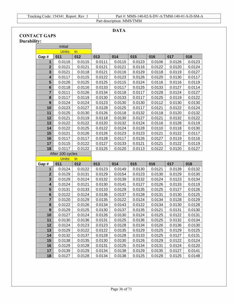
DATA CONTACT GAPS Durability:
Initial Units: in
Gap # 011 012 013 014 015 016 017 018 1 0.0116 0.0115 0.0111 0.0115 0.0123 0.0106 0.0126 0.01232 0.0121 0.0121 0.0121 0.0121 0.0116 0.0122 0.0120 0.01243 0.0121 0.0118 0.0121 0.0116 0.0129 0.0118 0.0119 0.01274 0.0117 0.0115 0.0122 0.0123 0.0126 0.0120 0.0130 0.01175 0.0126 0.0125 0.0125 0.0115 0.0124 0.0116 0.0116 0.01196 0.0118 0.0116 0.0133 0.0117 0.0125 0.0133 0.0127 0.01147 0.0111 0.0126 0.0134 0.0118 0.0117 0.0128 0.0124 0.01278 0.0117 0.0119 0.0130 0.0133 0.0117 0.0125 0.0119 0.01229 0.0124 0.0124 0.0123 0.0130 0.0130 0.0112 0.0130 0.0130
10 0.0123 0.0127 0.0128 0.0125 0.0117 0.0121 0.0122 0.012411 0.0125 0.0130 0.0126 0.0118 0.0132 0.0118 0.0120 0.013212 0.0121 0.0119 0.0118 0.0130 0.0127 0.0121 0.0132 0.012213 0.0122 0.0122 0.0120 0.0132 0.0124 0.0116 0.0128 0.011914 0.0122 0.0125 0.0122 0.0124 0.0128 0.0110 0.0118 0.013015 0.0121 0.0126 0.0126 0.0123 0.0123 0.0121 0.0122 0.011716 0.0117 0.0117 0.0128 0.0117 0.0126 0.0127 0.0119 0.011617 0.0115 0.0122 0.0127 0.0133 0.0121 0.0121 0.0122 0.011918 0.0117 0.0122 0.0125 0.0120 0.0113 0.0122 0.0120 0.0127
After 100 cycles Units: in
Gap # 011 012 013 014 015 016 017 018 1 0.0124 0.0122 0.0123 0.0149 0.0130 0.0121 0.0139 0.01322 0.0129 0.0131 0.0129 0.0154 0.0123 0.0130 0.0129 0.01303 0.0129 0.0124 0.0132 0.0139 0.0132 0.0124 0.0123 0.01344 0.0124 0.0121 0.0130 0.0141 0.0127 0.0126 0.0133 0.01195 0.0131 0.0133 0.0133 0.0129 0.0135 0.0125 0.0127 0.01266 0.0122 0.0124 0.0136 0.0137 0.0128 0.0131 0.0130 0.01257 0.0120 0.0129 0.0135 0.0122 0.0124 0.0134 0.0128 0.01298 0.0122 0.0126 0.0134 0.0143 0.0122 0.0134 0.0130 0.01289 0.0129 0.0125 0.0130 0.0137 0.0135 0.0121 0.0131 0.0130
10 0.0127 0.0124 0.0126 0.0130 0.0124 0.0125 0.0122 0.013111 0.0130 0.0136 0.0131 0.0125 0.0136 0.0125 0.0132 0.013412 0.0124 0.0123 0.0123 0.0128 0.0134 0.0126 0.0136 0.013013 0.0129 0.0122 0.0122 0.0135 0.0129 0.0125 0.0129 0.012514 0.0132 0.0137 0.0128 0.0128 0.0133 0.0125 0.0127 0.013115 0.0138 0.0135 0.0130 0.0130 0.0126 0.0129 0.0122 0.012416 0.0129 0.0128 0.0131 0.0125 0.0134 0.0131 0.0124 0.012017 0.0139 0.0129 0.0134 0.0138 0.0129 0.0135 0.0127 0.014118 0.0127 0.0128 0.0134 0.0138 0.0125 0.0128 0.0125 0.0148

Tracking Code: 154341_Report_Rev_1 Part #: MMS-140-02-S-DV-A/TMM-140-01-S-D-SM-A Part description: MMS/TMM
Page 37 of 71
DATA Continued Thermal aging:
Initial Units: in
Gap # 011 012 013 014 015 016 017 018 1 0.0143 0.0137 0.0141 0.0139 0.0141 0.0133 0.0130 0.01412 0.0143 0.0134 0.0136 0.0143 0.0144 0.0141 0.0135 0.01363 0.0141 0.0133 0.0139 0.0139 0.0147 0.0133 0.0130 0.01444 0.0148 0.0133 0.0139 0.0140 0.0147 0.0135 0.0139 0.01405 0.0141 0.0136 0.0140 0.0139 0.0144 0.0143 0.0134 0.01396 0.0146 0.0132 0.0139 0.0140 0.0137 0.0139 0.0138 0.01427 0.0146 0.0135 0.0136 0.0136 0.0143 0.0143 0.0137 0.01398 0.0141 0.0135 0.0142 0.0128 0.0142 0.0140 0.0139 0.01439 0.0142 0.0138 0.0141 0.0139 0.0140 0.0137 0.0137 0.0134
10 0.0143 0.0138 0.0137 0.0143 0.0133 0.0143 0.0134 0.013811 0.0147 0.0136 0.0139 0.0137 0.0142 0.0140 0.0136 0.014412 0.0143 0.0136 0.0136 0.0140 0.0143 0.0135 0.0136 0.014113 0.0143 0.0134 0.0137 0.0137 0.0143 0.0143 0.0136 0.013914 0.0139 0.0132 0.0140 0.0137 0.0143 0.0143 0.0140 0.014715 0.0145 0.0134 0.0141 0.0140 0.0141 0.0142 0.0133 0.013316 0.0139 0.0130 0.0136 0.0141 0.0134 0.0142 0.0126 0.013917 0.0142 0.0131 0.0137 0.0134 0.0140 0.0137 0.0136 0.014718 0.0143 0.0130 0.0138 0.0138 0.0136 0.0137 0.0136 0.0141
After thermal Units: in
Gap # 011 012 013 014 015 016 017 018 1 0.0149 0.0146 0.0146 0.0146 0.0149 0.0137 0.0141 0.01412 0.0147 0.0140 0.0147 0.0150 0.0150 0.0148 0.0136 0.01423 0.0143 0.0147 0.0145 0.0142 0.0144 0.0143 0.0143 0.01514 0.0150 0.0144 0.0150 0.0142 0.0149 0.0143 0.0146 0.01485 0.0146 0.0148 0.0147 0.0140 0.0142 0.0142 0.0135 0.01406 0.0149 0.0141 0.0151 0.0144 0.0143 0.0146 0.0143 0.01507 0.0147 0.0144 0.0142 0.0142 0.0144 0.0143 0.0146 0.01478 0.0143 0.0144 0.0149 0.0133 0.0144 0.0143 0.0139 0.01499 0.0142 0.0146 0.0147 0.0141 0.0138 0.0137 0.0135 0.0135
10 0.0145 0.0144 0.0143 0.0146 0.0143 0.0148 0.0141 0.014111 0.0148 0.0143 0.0144 0.0144 0.0144 0.0140 0.0139 0.014412 0.0144 0.0144 0.0144 0.0142 0.0144 0.0139 0.0140 0.014213 0.0147 0.0144 0.0146 0.0143 0.0148 0.0146 0.0144 0.014614 0.0146 0.0145 0.0150 0.0139 0.0146 0.0141 0.0140 0.014815 0.0144 0.0143 0.0146 0.0147 0.0140 0.0142 0.0141 0.013916 0.0140 0.0141 0.0144 0.0151 0.0147 0.0145 0.0133 0.014217 0.0146 0.0144 0.0148 0.0139 0.0143 0.0142 0.0139 0.014218 0.0146 0.0142 0.0144 0.0143 0.0145 0.0143 0.0139 0.0148

Tracking Code: 154341_Report_Rev_1 Part #: MMS-140-02-S-DV-A/TMM-140-01-S-D-SM-A Part description: MMS/TMM
Page 38 of 71
DATA continued Normal force initial:
Initial Units: inch
Pos.# B1 1 0.01352 0.01343 0.01394 0.01385 0.01406 0.01357 0.01338 0.01359 0.0137
10 0.013611 0.013512 0.013313 0.013714 0.013515 0.013216 0.013317 0.013318 0.0133

Tracking Code: 154341_Report_Rev_1 Part #: MMS-140-02-S-DV-A/TMM-140-01-S-D-SM-A Part description: MMS/TMM
Page 39 of 71
DATA continued Normal force thermal aging:
Initial After thermal Units: inch
Pos.# B1 B1 1 0.0132 0.01432 0.0139 0.01483 0.0142 0.01494 0.0135 0.01455 0.0135 0.01466 0.0136 0.01477 0.0138 0.01418 0.0141 0.01469 0.0139 0.0141
10 0.0136 0.014011 0.0138 0.014312 0.0133 0.013813 0.0130 0.014114 0.0133 0.014415 0.0125 0.013616 0.0125 0.013617 0.0133 0.014518 0.0125 0.013619 0.0137 0.014220 0.0142 0.014121 0.0144 0.014522 0.0139 0.014423 0.0135 0.013724 0.0137 0.013925 0.0138 0.013926 0.0141 0.014127 0.0139 0.013828 0.0141 0.014129 0.0142 0.014530 0.0142 0.014331 0.0142 0.014332 0.0143 0.014633 0.0143 0.014434 0.0137 0.014435 0.0136 0.014036 0.0133 0.0136

Tracking Code: 154341_Report_Rev_1 Part #: MMS-140-02-S-DV-A/TMM-140-01-S-D-SM-A Part description: MMS/TMM
Page 40 of 71
DATA continued MATING\UNMATING FORCE Mating/Unmating durability: (SMS-150-01-L-D/TMS-150-01-L-D)
Initial After 25 Cycles After 50 Cycles After 75 Cycles After 100 Cycles After Humidity Sample# Mating Unmating Mating Unmating Mating Unmating Mating Unmating Mating Unmating Mating Unmating
1 15.03 10.22 20.92 14.04 21.59 15.89 22.74 16.91 23.83 17.66 14.57 9.72 2 14.47 10.07 20.75 13.77 21.13 15.70 22.08 16.55 22.88 17.19 15.28 9.71 3 14.36 10.34 19.58 13.83 20.47 15.55 20.99 16.67 21.74 17.40 15.12 10.08 4 13.37 9.74 15.89 11.45 15.74 12.44 15.99 13.48 16.35 14.41 13.61 9.32 5 12.82 8.37 16.92 11.14 16.87 12.86 17.04 13.87 17.67 14.87 14.27 9.87 6 12.77 8.71 15.99 11.96 16.67 13.50 17.27 14.42 17.78 15.26 12.61 9.95 7 14.93 9.23 19.82 13.48 20.07 15.17 20.89 16.16 21.77 17.04 14.12 10.11 8 13.49 9.39 16.67 13.00 17.61 14.32 18.19 15.54 19.05 15.94 12.98 9.63
Mating/Unmating Basic (MMS-125-02-S-DV-A/ TMM-125-01-S-D-SM-A):
Initial 25 Cycles 50 Cycles 75 Cycles 100 Cycles Sample# Mating Unmating Mating Unmating Mating Unmating Mating Unmating Mating Unmating
1 9.02 7.45 10.43 7.61 10.41 8.46 10.78 9.10 11.23 9.43 2 8.80 7.20 9.98 7.41 9.88 8.26 10.18 8.59 10.24 8.99 3 7.98 7.74 10.09 8.27 10.21 8.81 10.45 9.48 10.60 9.87 4 9.09 7.29 10.79 7.91 10.71 8.65 11.02 9.40 11.25 9.88 5 10.03 7.33 11.15 7.92 11.00 8.74 11.60 9.16 11.94 9.68 6 8.88 7.39 10.56 7.09 10.47 7.98 10.80 8.51 11.06 9.03 7 9.48 7.17 10.33 6.90 10.12 7.53 10.34 8.41 10.49 8.73 8 10.87 7.30 11.09 7.58 10.86 8.21 10.99 8.84 11.30 9.36
Mating/Unmating Basic (MMS-105-02-S-DV-A/ TMM-105-01-S-D-SM-A):
Initial 25 Cycles 50 Cycles 75 Cycles 100 Cycles Sample# Mating Unmating Mating Unmating Mating Unmating Mating Unmating Mating Unmating
1 1.88 1.46 2.13 1.48 2.07 1.62 2.16 1.78 2.22 1.90 2 2.27 1.41 2.16 1.52 2.19 1.69 2.23 1.67 2.30 1.86 3 1.78 1.34 2.18 1.30 1.91 1.45 1.88 1.60 1.91 1.70 4 2.02 1.41 2.18 1.39 2.07 1.51 1.99 1.61 1.98 1.72 5 2.10 1.42 2.02 1.39 1.96 1.54 1.98 1.68 2.01 1.81 6 2.04 1.43 2.13 1.50 2.11 1.73 2.19 1.88 2.26 2.00 7 2.29 1.60 2.28 1.60 2.26 1.71 2.29 1.87 2.34 1.91 8 2.12 1.51 1.98 1.48 1.95 1.67 2.02 1.82 2.07 1.83

Tracking Code: 154341_Report_Rev_1 Part #: MMS-140-02-S-DV-A/TMM-140-01-S-D-SM-A Part description: MMS/TMM
Page 41 of 71
DATA Continued Thermal aging:
Initial After Thermals Sample# Mating Unmating Mating Unmating
1 8.53 6.01 9.23 7.40 2 8.57 7.01 9.98 7.76 3 8.47 6.66 9.32 7.79 4 8.22 6.95 9.87 8.76 5 8.74 7.62 9.38 7.82 6 9.02 7.40 8.51 7.56 7 8.80 6.40 9.16 7.85 8 8.18 5.94 8.36 7.21
NORMAL FORCE
Initial Deflections in inches, Forces in Grams Sample
# 0.0005 0.0009 0.0014 0.0018 0.0023 0.0027 0.0032 0.0036 0.0041 0.0045 SET 1 12.1 21.9 31.6 42.3 51.2 60.0 67.9 74.7 83.0 92.2 0.0002 2 9.6 19.0 28.5 38.0 47.1 55.9 64.5 73.5 82.0 89.9 0.0002 3 9.5 19.2 28.9 37.8 47.3 56.4 65.1 74.3 82.6 91.0 0.0002 4 8.4 17.4 26.3 35.2 43.6 52.5 60.6 68.8 77.8 85.4 0.0002 5 9.2 18.5 27.0 36.1 44.2 52.6 60.8 67.4 74.6 80.2 0.0004 6 9.8 19.7 28.7 38.0 46.6 55.7 65.1 73.1 81.8 88.3 0.0002 7 9.8 19.2 28.3 38.7 47.3 56.7 65.1 74.7 83.4 91.6 0.0001 8 9.9 19.4 28.9 38.2 47.0 54.4 61.4 67.7 74.0 80.8 0.0005 9 8.8 18.3 27.0 35.8 44.0 52.6 61.6 69.7 78.1 86.0 0.0003
10 9.2 18.4 28.0 36.7 45.7 54.4 63.1 71.5 79.9 88.4 0.0002 11 13.3 23.1 33.0 41.0 50.1 59.4 68.5 77.2 85.2 94.0 0.0004 12 8.9 18.0 26.2 35.1 44.4 52.5 61.0 69.1 77.2 85.0 0.0004
After
Thermals Deflections in inches, Forces in Grams Sample # 0.0004 0.0008 0.0012 0.0016 0.0020 0.0024 0.0028 0.0032 0.0036 0.0040 SET
1 8.5 16.5 24.7 33.0 40.5 47.4 54.4 60.5 67.0 72.3 0.0003 2 8.4 16.8 24.6 32.5 40.8 48.5 56.3 64.1 71.9 79.4 0.0002 3 7.7 15.9 24.2 31.8 39.2 46.7 53.7 60.5 67.0 73.3 0.0003 4 7.9 14.7 21.0 28.2 34.4 40.6 46.2 52.3 58.4 64.7 0.0007 5 8.9 15.8 21.8 28.0 34.1 40.0 45.9 52.0 57.0 63.0 0.0007 6 9.3 17.6 25.5 33.5 41.1 48.7 55.7 62.4 68.8 75.4 0.0006 7 6.2 15.9 23.7 31.6 38.4 45.6 52.3 59.5 65.6 71.8 0.0008 8 8.6 17.0 25.1 32.7 39.5 45.7 52.0 59.2 65.0 71.1 0.0006 9 8.1 16.8 24.4 33.0 40.4 48.4 55.8 64.0 71.3 78.8 0.0003
10 8.6 17.8 27.0 35.2 43.3 50.4 57.5 64.2 70.2 76.9 0.0004 11 8.2 17.7 26.5 35.7 44.1 52.3 60.0 67.3 74.4 81.4 0.0003 12 9.3 17.8 26.1 33.4 41.4 48.9 56.2 63.4 69.3 76.4 0.0003

Tracking Code: 154341_Report_Rev_1 Part #: MMS-140-02-S-DV-A/TMM-140-01-S-D-SM-A Part description: MMS/TMM
Page 42 of 71
DATA continued INSULATION RESISTANCE (IR):
Initial Insulation Resistance Measured In Meg Ohms Pin to Pin Mated A Unmated B
X X X Sample# MMS/TMM MMS TMM
154341-031 100000 100000 100000 154341-032 100000 100000 100000
Row to Row Mated A Unmated B
X X X Sample# MMS/TMM MMS TMM
154341-037 100000 100000 100000 154341-038 100000 100000 100000
Thermal Insulation Resistance Measured In Meg Ohms Pin to Pin Mated A Unmated B
X X X Sample# MMS/TMM MMS TMM
154341-031 100000 100000 100000 154341-032 100000 100000 100000
Row to Row Mated A Unmated B
X X X Sample# MMS/TMM MMS TMM
154341-037 100000 100000 100000 154341-038 100000 100000 100000

Tracking Code: 154341_Report_Rev_1 Part #: MMS-140-02-S-DV-A/TMM-140-01-S-D-SM-A Part description: MMS/TMM
Page 43 of 71
DATA continued
Humidity Insulation Resistance Measured In Meg Ohms Pin to Pin Mated A Unmated B
X X X Sample# MMS/TMM MMS TMM
154341-031 100000 100000 100000 154341-032 100000 100000 100000
Row to Row Mated A Unmated B
X X X Sample# MMS/TMM MMS TMM
154341-037 100000 60000 100000 154341-038 100000 100000 100000
DIELECTRIC WITHSTANDING VOLTAGE (DWV):
Initial Breakdown Voltage Test Voltage Until Breakdown Occurs Pin to Pin Mated A Unmated B
X Sample# MMS/TMM MMS TMM
154341-027 1700 1500 1600 154341-028 1600 1500 1700
Row to Row Mated A Unmated B
X Sample# MMS/TMM MMS TMM
154341-033 1400 1700 1800 154341-034 1700 1800 1800
Tracking Code: 154341_Report_Rev_1 Part #: MMS-140-02-S-DV-A/TMM-140-01-S-D-SM-A Part description: MMS/TMM
Page 44 of 71
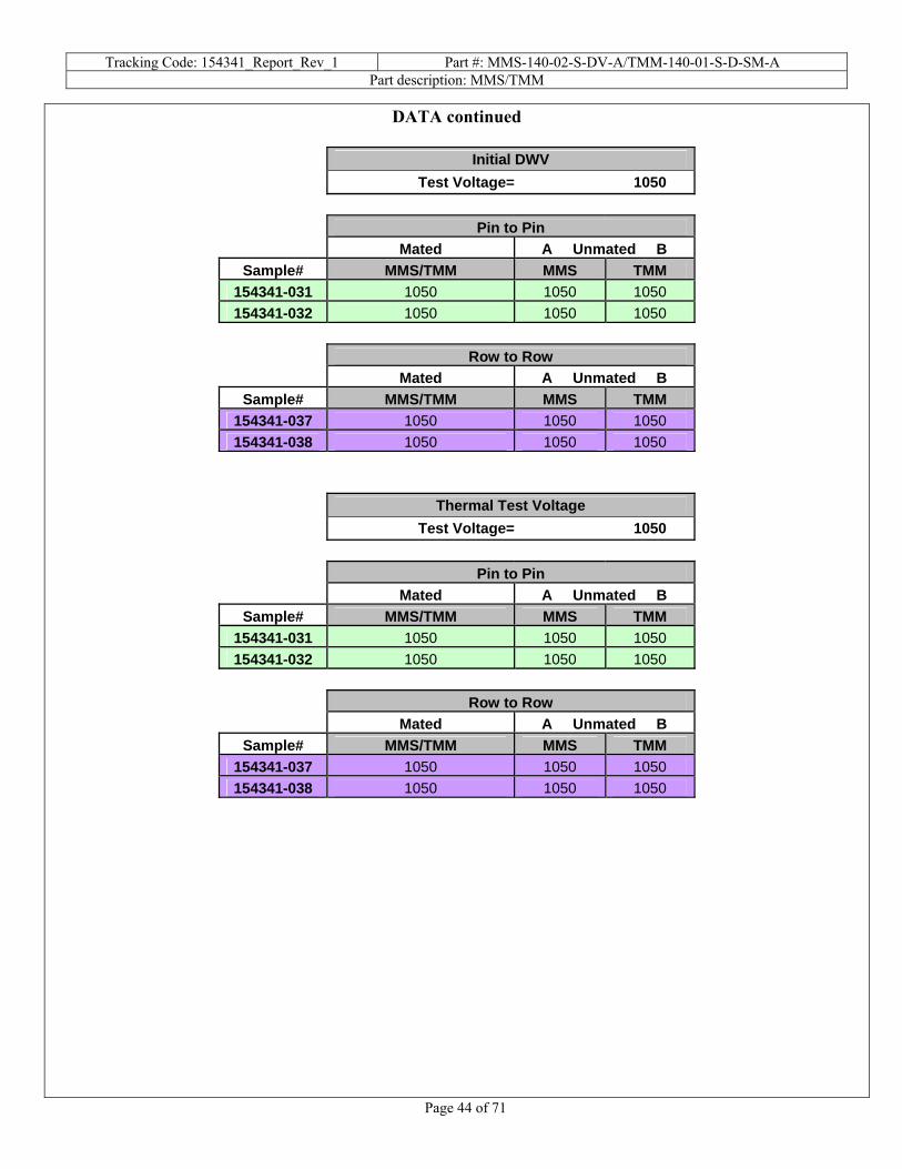
DATA continued
Initial DWV Test Voltage= 1050 Pin to Pin Mated A Unmated B
Sample# MMS/TMM MMS TMM 154341-031 1050 1050 1050 154341-032 1050 1050 1050
Row to Row Mated A Unmated B
Sample# MMS/TMM MMS TMM 154341-037 1050 1050 1050 154341-038 1050 1050 1050
Thermal Test Voltage Test Voltage= 1050 Pin to Pin Mated A Unmated B
Sample# MMS/TMM MMS TMM 154341-031 1050 1050 1050 154341-032 1050 1050 1050
Row to Row Mated A Unmated B
Sample# MMS/TMM MMS TMM 154341-037 1050 1050 1050 154341-038 1050 1050 1050

Tracking Code: 154341_Report_Rev_1 Part #: MMS-140-02-S-DV-A/TMM-140-01-S-D-SM-A Part description: MMS/TMM
Page 45 of 71
DATA continued
Humidity Test Voltage Test Voltage= 1050 Pin to Pin Mated A Unmated B
Sample# MMS/TMM MMS TMM 154341-031 1050 1050 1050 154341-032 1050 1050 1050
Row to Row Mated A Unmated B
Sample# MMS/TMM MMS TMM 154341-037 1050 1050 1050 154341-038 1050 1050 1050
Tracking Code: 154341_Report_Rev_1 Part #: MMS-140-02-S-DV-A/TMM-140-01-S-D-SM-A Part description: MMS/TMM
Page 46 of 71
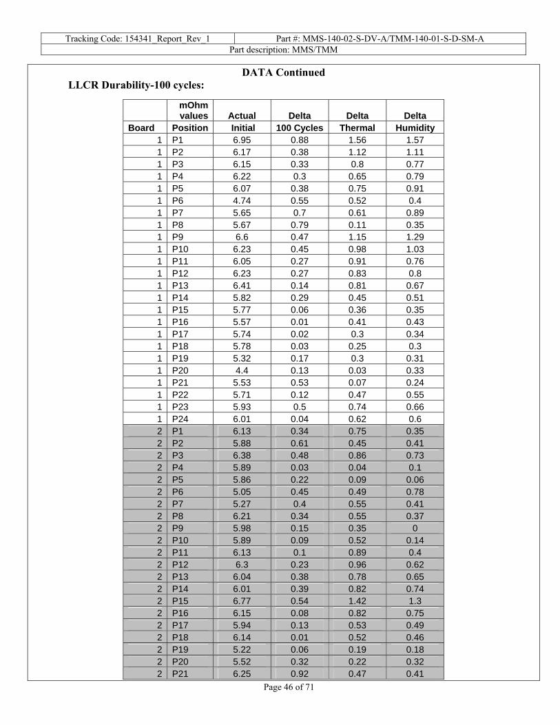
DATA Continued LLCR Durability-100 cycles:
mOhm values Actual Delta Delta Delta
Board Position Initial 100 Cycles Thermal Humidity 1 P1 6.95 0.88 1.56 1.57 1 P2 6.17 0.38 1.12 1.11 1 P3 6.15 0.33 0.8 0.77 1 P4 6.22 0.3 0.65 0.79 1 P5 6.07 0.38 0.75 0.91 1 P6 4.74 0.55 0.52 0.4 1 P7 5.65 0.7 0.61 0.89 1 P8 5.67 0.79 0.11 0.35 1 P9 6.6 0.47 1.15 1.29 1 P10 6.23 0.45 0.98 1.03 1 P11 6.05 0.27 0.91 0.76 1 P12 6.23 0.27 0.83 0.8 1 P13 6.41 0.14 0.81 0.67 1 P14 5.82 0.29 0.45 0.51 1 P15 5.77 0.06 0.36 0.35 1 P16 5.57 0.01 0.41 0.43 1 P17 5.74 0.02 0.3 0.34 1 P18 5.78 0.03 0.25 0.3 1 P19 5.32 0.17 0.3 0.31 1 P20 4.4 0.13 0.03 0.33 1 P21 5.53 0.53 0.07 0.24 1 P22 5.71 0.12 0.47 0.55 1 P23 5.93 0.5 0.74 0.66 1 P24 6.01 0.04 0.62 0.6 2 P1 6.13 0.34 0.75 0.35 2 P2 5.88 0.61 0.45 0.41 2 P3 6.38 0.48 0.86 0.73 2 P4 5.89 0.03 0.04 0.1 2 P5 5.86 0.22 0.09 0.06 2 P6 5.05 0.45 0.49 0.78 2 P7 5.27 0.4 0.55 0.41 2 P8 6.21 0.34 0.55 0.37 2 P9 5.98 0.15 0.35 0 2 P10 5.89 0.09 0.52 0.14 2 P11 6.13 0.1 0.89 0.4 2 P12 6.3 0.23 0.96 0.62 2 P13 6.04 0.38 0.78 0.65 2 P14 6.01 0.39 0.82 0.74 2 P15 6.77 0.54 1.42 1.3 2 P16 6.15 0.08 0.82 0.75 2 P17 5.94 0.13 0.53 0.49 2 P18 6.14 0.01 0.52 0.46 2 P19 5.22 0.06 0.19 0.18 2 P20 5.52 0.32 0.22 0.32 2 P21 6.25 0.92 0.47 0.41

Tracking Code: 154341_Report_Rev_1 Part #: MMS-140-02-S-DV-A/TMM-140-01-S-D-SM-A Part description: MMS/TMM
Page 47 of 71
2 P22 6.11 0.15 0.64 0.48 2 P23 6.16 0.27 0.71 0.6 2 P24 6.19 0.27 0.74 0.73 3 P1 6.59 0.16 0.53 0.52 3 P2 6.8 0.56 0.92 0.87 3 P3 6.77 0.56 0.75 0.68 3 P4 6.93 0.46 0.75 0.77 3 P5 6.11 0.03 0.01 0.07 3 P6 5.2 0.21 0.1 0.21 3 P7 5.61 0.44 0.39 0.43 3 P8 6.15 0.1 0.21 0.33 3 P9 6.46 0.48 0.66 0.69 3 P10 6.64 0.52 0.85 0.8 3 P11 7.02 0.61 1.06 1.03 3 P12 6.92 0.21 0.95 0.95 3 P13 6.51 0.26 0.64 0.62 3 P14 7.14 0.18 0.92 0.92 3 P15 6.42 0.03 0.47 0.39 3 P16 6.62 0.18 0.68 0.65 3 P17 6.37 0.06 0.46 0.44 3 P18 6.83 0.03 0.48 0.45 3 P19 5.58 0.09 0.02 0.06 3 P20 5.18 0.13 0.18 0.38 3 P21 6.46 0.11 0.44 0.49 3 P22 6.87 0.07 0.72 0.59 3 P23 6.29 0.04 0.57 0.57 3 P24 6.64 0.03 0.65 0.72 4 P1 7.16 0.59 1.56 1.42 4 P2 6.97 0.43 1.39 1.27 4 P3 6.31 0.23 0.41 0.35 4 P4 7.02 0.59 0.9 0.89 4 P5 6.45 0.35 0.65 0.72 4 P6 6.08 0.18 0.31 0.25 4 P7 5.27 0.56 0.68 1.31 4 P8 6.71 0.08 0.64 0.73 4 P9 7.52 0.04 1.4 1.46 4 P10 7 0.38 1.13 1.18 4 P11 6.84 0.7 1.03 0.92 4 P12 7.45 0.19 1.58 1.67 4 P13 6.92 0.74 1.29 1.37 4 P14 6.93 0.6 1.2 1.1 4 P15 7.15 0.1 1.25 1.3 4 P16 7.27 0.78 1.45 1.42 4 P17 6.6 0.19 0.72 0.73 4 P18 6.58 0.58 0.72 0.67 4 P19 4.8 0.3 0.24 0.61 4 P20 5.3 0.44 0.24 0.16 4 P21 6.04 1.86 0.24 0.41 4 P22 6.2 0.53 0.6 0.61 4 P23 6.45 0.42 0.83 0.79

Tracking Code: 154341_Report_Rev_1 Part #: MMS-140-02-S-DV-A/TMM-140-01-S-D-SM-A Part description: MMS/TMM
Page 48 of 71
4 P24 6.48 0.19 0.87 0.9 5 P1 6.93 0.62 1.29 1.28 5 P2 7.29 1.55 1.92 1.84 5 P3 7.6 0.47 1.84 1.81 5 P4 6.1 0.45 0.34 0.4 5 P5 6.04 0.09 0.26 0.32 5 P6 6.4 0.82 0.68 0.98 5 P7 5.77 0.05 0.18 0.47 5 P8 6.53 0.04 0.46 0.5 5 P9 7 0.92 0.95 1.04 5 P10 6.46 0.25 0.97 0.89 5 P11 7.9 1.05 2.31 2.41 5 P12 7.13 0.57 1.62 1.61 5 P13 6.05 0.26 0.54 0.55 5 P14 6.62 0.51 1.04 1.11 5 P15 6.12 0.15 0.65 0.65 5 P16 6.81 0.7 1.2 1.26 5 P17 6.65 3.25 0.84 1.07 5 P18 6.1 0.14 0.56 0.6 5 P19 5.48 0.02 0.58 0.5 5 P20 5.64 0.36 0.38 0.33 5 P21 6.03 0.78 0.41 0.44 5 P22 6.15 0.24 0.59 0.61 5 P23 6.48 2.5 0.76 0.85 5 P24 6.99 0.23 1.29 1.36 6 P1 6.87 0.6 1.4 1.41 6 P2 6.01 0.19 0.66 0.65 6 P3 7.13 1.15 1.61 1.69 6 P4 6.69 0.63 1.11 1.05 6 P5 6.25 0.62 0.73 0.72 6 P6 6.08 0.61 1.03 0.87 6 P7 5.8 0.6 0.56 0.68 6 P8 6.15 0.12 0.42 0.47 6 P9 6.15 0.09 0.4 0.59 6 P10 6.17 0.05 0.71 0.67 6 P11 6.21 0.14 0.71 0.61 6 P12 6.22 2.05 0.52 0.51 6 P13 6.08 0.37 0.43 0.5 6 P14 6.2 0.01 0.48 0.47 6 P15 6.37 0.2 0.7 0.65 6 P16 6.37 0.56 0.77 0.57 6 P17 6.01 0.03 0.58 0.54 6 P18 6.1 0.08 0.46 0.5 6 P19 5.67 0.13 0.49 0.53 6 P20 4.94 0.1 0.08 0.17 6 P21 6.91 0.49 1.03 1.12 6 P22 6.02 0.11 0.56 0.56 6 P23 6.21 0.31 0.81 0.92 6 P24 5.96 0.11 0.64 0.63 7 P1 6.2 0.32 0.52 0.52

Tracking Code: 154341_Report_Rev_1 Part #: MMS-140-02-S-DV-A/TMM-140-01-S-D-SM-A Part description: MMS/TMM
Page 49 of 71
7 P2 6.37 0.21 0.66 0.64 7 P3 6.17 0.14 0.57 0.55 7 P4 5.89 0 0.31 0.23 7 P5 6.9 0.82 1.1 1.3 7 P6 5.4 0.15 0.24 0.18 7 P7 5.81 0.38 0.38 0.22 7 P8 7 1 1.26 2.64 7 P9 5.88 0.21 0.5 0.38 7 P10 5.91 0.18 0.36 0.28 7 P11 5.97 0.81 0.25 0.24 7 P12 5.97 0.15 0.25 0.16 7 P13 6.26 0.36 0.64 0.64 7 P14 6.44 0.3 0.76 0.82 7 P15 6.19 0.06 0.27 0.39 7 P16 6.31 0.17 0.43 0.4 7 P17 6.5 0.26 0.74 0.68 7 P18 6.91 0.38 0.79 0.85 7 P19 5.76 0.48 0.43 0.33 7 P20 7.23 2.05 2.12 2.12 7 P21 6.52 0.45 0.99 1.03 7 P22 6.48 0.02 0.94 0.98 7 P23 7.8 1.06 2.08 2.23 7 P24 8 1.01 1.12 1.9 8 P1 6.8 0.15 1.13 1.17 8 P2 7.91 1.86 2.33 2.34 8 P3 6.66 0.4 0.56 0.67 8 P4 6.2 0.5 0.4 0.4 8 P5 6.47 0.42 0.51 0.67 8 P6 6.32 0.91 0.72 0.92 8 P7 6.91 1.01 1.02 0.13 8 P8 6.63 0.64 0.59 0.65 8 P9 6.69 0.78 0.95 0.93 8 P10 7.06 0.84 1.42 1.27 8 P11 7.56 1.19 1.83 1.81 8 P12 6.63 0.32 1.02 0.9 8 P13 6.43 0.38 0.74 0.81 8 P14 6.63 0.81 0.9 0.82 8 P15 6.34 0.06 0.24 0.49 8 P16 6.59 0.02 1.02 0.93 8 P17 6.18 0.41 0.59 0.58 8 P18 6.06 0.04 0.38 0.41 8 P19 6.22 0.08 0.49 0.58 8 P20 5.77 0.08 0.05 0.86 8 P21 6.76 0.67 0.83 0.81 8 P22 6.32 0.48 0.66 0.56 8 P23 7.86 1.86 2.34 2.4 8 P24 6.56 0.51 0.9 0.87

Tracking Code: 154341_Report_Rev_1 Part #: MMS-140-02-S-DV-A/TMM-140-01-S-D-SM-A Part description: MMS/TMM
Page 50 of 71
DATA Continued LLCR Durability-250 cycles:
mOhm values Actual Delta Delta Delta
Board Position Initial 250 Cycles Thermal Humidity 1 P1 5.64 0.39 0.59 0.54 1 P2 5.64 0.25 0.42 0.48 1 P3 5.98 0.61 0.73 0.61 1 P4 5.77 0.18 0.25 0.18 1 P5 5.89 0.34 0.39 0.05 1 P6 5.73 0.6 0.62 0.2 1 P7 5.6 0.34 0.28 0.05 1 P8 6.26 0.39 0.52 0.46 1 P9 6.24 0.42 0.61 0.61 1 P10 6.24 0.29 0.65 0.67 1 P11 6.43 0.85 0.91 0.94 1 P12 6.23 0.32 0.67 0.83 1 P13 6.08 0.05 0.37 0.28 1 P14 6.05 0.21 0.52 0.4 1 P15 6.04 0.29 0.48 0.41 1 P16 5.78 0.09 0.29 0.18 1 P17 5.73 0.23 0.35 0.19 1 P18 5.89 0.21 0.34 0.37 1 P19 5.32 0.09 0.27 0.22 1 P20 5.22 0.07 0.21 0.15 1 P21 5.89 0.55 0.58 0.63 1 P22 5.73 0.22 0.51 0.31 1 P23 5.57 0.1 0.38 0.27 1 P24 5.71 0.28 0.5 0.45 2 P1 6.08 0.14 0.28 0.38 2 P2 5.92 0.07 0.33 0.32 2 P3 5.91 0.03 0.1 0.11 2 P4 6.04 0 0.17 0.24 2 P5 5.87 0.02 0.14 0.07 2 P6 5.04 0.62 0.5 0.56 2 P7 5.41 0.08 0.22 0.09 2 P8 6.03 0.19 0.48 0.53 2 P9 5.85 0.02 0.17 0.25 2 P10 5.84 0.09 0.44 0.34 2 P11 5.6 0.04 0.17 0.2 2 P12 5.79 0.09 0.08 0.19 2 P13 5.69 0.24 0.42 0.19 2 P14 5.97 0.37 0.6 0.37 2 P15 5.74 0.11 0.45 0.34 2 P16 5.95 0.26 0.54 0.55 2 P17 6.11 0.53 0.71 0.81 2 P18 6.24 0.09 0.61 0.84 2 P19 5.59 0.02 0.01 0.19 2 P20 4.91 0.56 0.86 0.49 2 P21 6.01 0.2 0.45 0.51

Tracking Code: 154341_Report_Rev_1 Part #: MMS-140-02-S-DV-A/TMM-140-01-S-D-SM-A Part description: MMS/TMM
Page 51 of 71
2 P22 6.03 0.32 0.4 0.43 2 P23 6.04 0.26 0.51 0.44 2 P24 6.43 0.55 0.72 0.73 3 P1 8.13 2.34 2.73 2.68 3 P2 6 0.3 0.53 0.47 3 P3 8.7 2.67 2.95 2.89 3 P4 6.25 0.58 0.72 0.73 3 P5 6.2 0.44 0.46 0.36 3 P6 5.85 0.89 0.84 0.75 3 P7 7.25 2.18 1.73 1.68 3 P8 6.26 0.24 0.6 0.53 3 P9 8.3 2.59 2.68 2.83 3 P10 6.95 1.07 1.43 1.51 3 P11 6.82 1.19 1.5 1.42 3 P12 7.3 1.5 1.84 1.79 3 P13 6.45 0.71 0.95 0.99 3 P14 7.01 0.75 1.45 1.52 3 P15 6.31 0.43 0.71 0.77 3 P16 6.45 0.67 0.92 1.01 3 P17 6.53 0.61 0.95 0.91 3 P18 7.19 1.3 1.55 1.63 3 P19 6.01 0.78 0.87 0.9 3 P20 5.85 0.56 0.7 0.67 3 P21 6.35 0.29 0.75 0.77 3 P22 6.17 0.52 0.7 0.62 3 P23 6.17 0.49 0.72 0.55 3 P24 6.12 0.41 0.69 0.62 4 P1 6.18 0.21 0.7 0.74 4 P2 6.27 0.23 0.84 0.84 4 P3 6.4 0.84 0.97 0.85 4 P4 6.06 0.41 0.32 0.29 4 P5 5.69 0.33 0.17 0.13 4 P6 5.51 0.4 0.09 0.14 4 P7 7.62 2.7 2.56 2.67 4 P8 5.95 0.19 0.24 0.1 4 P9 6.27 0.23 0.71 0.54 4 P10 6.91 1.11 1.34 1.38 4 P11 6.24 0.32 0.55 0.58 4 P12 7.18 1.13 1.47 1.58 4 P13 6 0.13 0.55 0.55 4 P14 5.99 0.04 0.65 0.58 4 P15 6.7 0.8 1.08 1.13 4 P16 6.8 0.4 1.21 1.3 4 P17 5.96 0.58 0.53 0.53 4 P18 5.98 0.31 0.36 0.31 4 P19 5.23 0.06 0.16 0.24 4 P20 5.53 0.07 0.2 0.12 4 P21 5.7 0.03 0.41 0.41 4 P22 6.14 0.34 0.74 0.69 4 P23 5.82 0.07 0.56 0.53
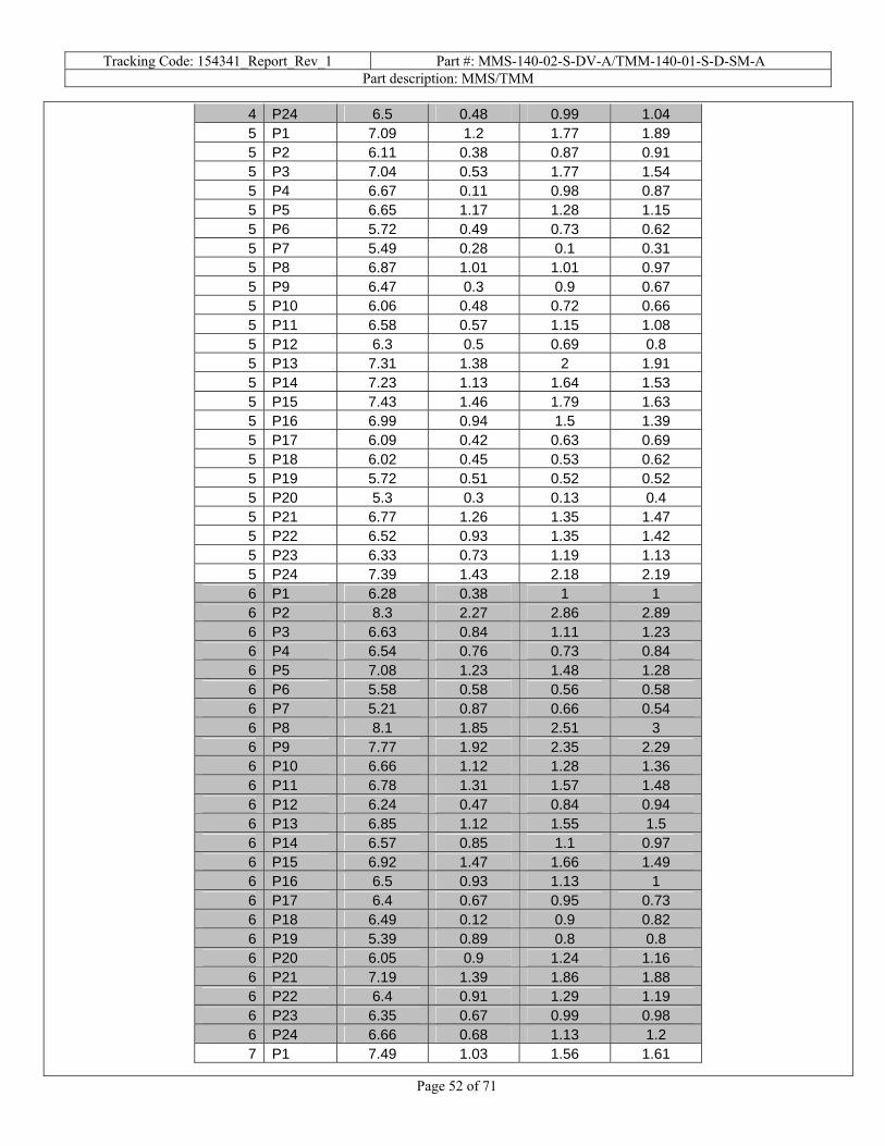
Tracking Code: 154341_Report_Rev_1 Part #: MMS-140-02-S-DV-A/TMM-140-01-S-D-SM-A Part description: MMS/TMM
Page 52 of 71
4 P24 6.5 0.48 0.99 1.04 5 P1 7.09 1.2 1.77 1.89 5 P2 6.11 0.38 0.87 0.91 5 P3 7.04 0.53 1.77 1.54 5 P4 6.67 0.11 0.98 0.87 5 P5 6.65 1.17 1.28 1.15 5 P6 5.72 0.49 0.73 0.62 5 P7 5.49 0.28 0.1 0.31 5 P8 6.87 1.01 1.01 0.97 5 P9 6.47 0.3 0.9 0.67 5 P10 6.06 0.48 0.72 0.66 5 P11 6.58 0.57 1.15 1.08 5 P12 6.3 0.5 0.69 0.8 5 P13 7.31 1.38 2 1.91 5 P14 7.23 1.13 1.64 1.53 5 P15 7.43 1.46 1.79 1.63 5 P16 6.99 0.94 1.5 1.39 5 P17 6.09 0.42 0.63 0.69 5 P18 6.02 0.45 0.53 0.62 5 P19 5.72 0.51 0.52 0.52 5 P20 5.3 0.3 0.13 0.4 5 P21 6.77 1.26 1.35 1.47 5 P22 6.52 0.93 1.35 1.42 5 P23 6.33 0.73 1.19 1.13 5 P24 7.39 1.43 2.18 2.19 6 P1 6.28 0.38 1 1 6 P2 8.3 2.27 2.86 2.89 6 P3 6.63 0.84 1.11 1.23 6 P4 6.54 0.76 0.73 0.84 6 P5 7.08 1.23 1.48 1.28 6 P6 5.58 0.58 0.56 0.58 6 P7 5.21 0.87 0.66 0.54 6 P8 8.1 1.85 2.51 3 6 P9 7.77 1.92 2.35 2.29 6 P10 6.66 1.12 1.28 1.36 6 P11 6.78 1.31 1.57 1.48 6 P12 6.24 0.47 0.84 0.94 6 P13 6.85 1.12 1.55 1.5 6 P14 6.57 0.85 1.1 0.97 6 P15 6.92 1.47 1.66 1.49 6 P16 6.5 0.93 1.13 1 6 P17 6.4 0.67 0.95 0.73 6 P18 6.49 0.12 0.9 0.82 6 P19 5.39 0.89 0.8 0.8 6 P20 6.05 0.9 1.24 1.16 6 P21 7.19 1.39 1.86 1.88 6 P22 6.4 0.91 1.29 1.19 6 P23 6.35 0.67 0.99 0.98 6 P24 6.66 0.68 1.13 1.2 7 P1 7.49 1.03 1.56 1.61

Tracking Code: 154341_Report_Rev_1 Part #: MMS-140-02-S-DV-A/TMM-140-01-S-D-SM-A Part description: MMS/TMM
Page 53 of 71
7 P2 7.11 0.84 1.25 1.24 7 P3 6.72 0.77 1.04 0.97 7 P4 6.92 0.75 0.98 1.01 7 P5 7.15 1.15 1.15 1.19 7 P6 6.09 0.18 0.03 0.23 7 P7 6.06 1.67 1.09 1.02 7 P8 7.81 1.33 1.86 1.82 7 P9 7.22 1.19 1.48 1.52 7 P10 6.19 0.08 0.64 0.69 7 P11 6.08 0.09 0.54 0.51 7 P12 6.2 0.3 0.61 0.65 7 P13 6.81 0.82 1.13 1.14 7 P14 6.69 0.37 0.78 0.82 7 P15 6.62 0.53 0.9 0.9 7 P16 6.43 0.27 0.77 0.8 7 P17 6.32 0.33 0.69 0.68 7 P18 6.67 0.17 0.79 0.83 7 P19 5.3 0.11 0.34 0.2 7 P20 5.53 0.11 0.19 0.21 7 P21 7 1.05 1.15 1.17 7 P22 7.97 1.2 1.85 1.95 7 P23 7.34 1.25 1.66 1.64 7 P24 7.18 0.97 1.29 1.35 8 P1 7.22 1.07 1.78 1.83 8 P2 6.72 0.64 1.08 0.92 8 P3 6.49 0.58 1.19 1.18 8 P4 6.5 0.9 1.2 1.1 8 P5 6.05 0.58 0.65 0.58 8 P6 5.53 0.36 0.52 0.55 8 P7 6.09 0.77 0.92 0.93 8 P8 6.39 0.47 0.62 0.79 8 P9 6.7 0.66 0.95 0.84 8 P10 7.22 1.13 1.54 1.59 8 P11 7.53 1.67 1.95 1.96 8 P12 7.93 1.96 2.27 2.34 8 P13 9 2.85 3.49 3.5 8 P14 6.92 0.93 1.29 1.09 8 P15 6.96 0.57 1.43 1.36 8 P16 6.83 1.02 1.32 1.24 8 P17 7.56 1.56 1.84 1.81 8 P18 7.75 1.51 2.02 1.95 8 P19 7.72 2.4 2.54 2.62 8 P20 7.33 2.61 2.58 2.63 8 P21 6.91 0.88 1.41 1.42 8 P22 7.54 1.39 2.12 2.06 8 P23 6.36 0.54 1 0.97 8 P24 6.95 1.27 1.65 1.62
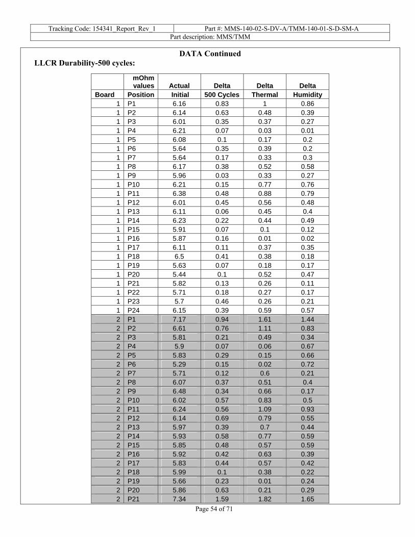
Tracking Code: 154341_Report_Rev_1 Part #: MMS-140-02-S-DV-A/TMM-140-01-S-D-SM-A Part description: MMS/TMM
Page 54 of 71
DATA Continued LLCR Durability-500 cycles:
mOhm values Actual Delta Delta Delta
Board Position Initial 500 Cycles Thermal Humidity 1 P1 6.16 0.83 1 0.86 1 P2 6.14 0.63 0.48 0.39 1 P3 6.01 0.35 0.37 0.27 1 P4 6.21 0.07 0.03 0.01 1 P5 6.08 0.1 0.17 0.2 1 P6 5.64 0.35 0.39 0.2 1 P7 5.64 0.17 0.33 0.3 1 P8 6.17 0.38 0.52 0.58 1 P9 5.96 0.03 0.33 0.27 1 P10 6.21 0.15 0.77 0.76 1 P11 6.38 0.48 0.88 0.79 1 P12 6.01 0.45 0.56 0.48 1 P13 6.11 0.06 0.45 0.4 1 P14 6.23 0.22 0.44 0.49 1 P15 5.91 0.07 0.1 0.12 1 P16 5.87 0.16 0.01 0.02 1 P17 6.11 0.11 0.37 0.35 1 P18 6.5 0.41 0.38 0.18 1 P19 5.63 0.07 0.18 0.17 1 P20 5.44 0.1 0.52 0.47 1 P21 5.82 0.13 0.26 0.11 1 P22 5.71 0.18 0.27 0.17 1 P23 5.7 0.46 0.26 0.21 1 P24 6.15 0.39 0.59 0.57 2 P1 7.17 0.94 1.61 1.44 2 P2 6.61 0.76 1.11 0.83 2 P3 5.81 0.21 0.49 0.34 2 P4 5.9 0.07 0.06 0.67 2 P5 5.83 0.29 0.15 0.66 2 P6 5.29 0.15 0.02 0.72 2 P7 5.71 0.12 0.6 0.21 2 P8 6.07 0.37 0.51 0.4 2 P9 6.48 0.34 0.66 0.17 2 P10 6.02 0.57 0.83 0.5 2 P11 6.24 0.56 1.09 0.93 2 P12 6.14 0.69 0.79 0.55 2 P13 5.97 0.39 0.7 0.44 2 P14 5.93 0.58 0.77 0.59 2 P15 5.85 0.48 0.57 0.59 2 P16 5.92 0.42 0.63 0.39 2 P17 5.83 0.44 0.57 0.42 2 P18 5.99 0.1 0.38 0.22 2 P19 5.66 0.23 0.01 0.24 2 P20 5.86 0.63 0.21 0.29 2 P21 7.34 1.59 1.82 1.65

Tracking Code: 154341_Report_Rev_1 Part #: MMS-140-02-S-DV-A/TMM-140-01-S-D-SM-A Part description: MMS/TMM
Page 55 of 71
2 P22 5.87 0.29 0.56 0.36 2 P23 5.95 0.45 0.28 0.16 2 P24 5.98 0.11 0.26 0.02 3 P1 7.15 1.29 1.71 1.62 3 P2 6.59 1.09 1.47 1.39 3 P3 6.94 1.15 1.81 1.51 3 P4 7.02 1.15 1.1 0.98 3 P5 7.6 2.02 2.04 1.9 3 P6 6.99 1.76 2.46 1.77 3 P7 6.21 1.07 1.25 1.08 3 P8 6.08 0.64 0.85 0.84 3 P9 6.07 0.48 0.73 0.63 3 P10 6.22 0.49 1.02 1.1 3 P11 6.28 0.59 1.2 1.17 3 P12 6.16 0.87 1.12 1.09 3 P13 6.68 1 1.3 1.2 3 P14 6.81 1.3 1.54 1.41 3 P15 6.12 0.49 0.89 0.77 3 P16 5.96 0.46 0.6 0.55 3 P17 6.07 0.8 0.79 0.61 3 P18 7.03 1.49 1.66 1.44 3 P19 5.7 0.82 0.84 0.64 3 P20 5.69 0.82 0.84 0.71 3 P21 7.32 1.29 1.42 1.38 3 P22 6.05 0.81 0.95 0.86 3 P23 5.83 0.39 0.69 0.59 3 P24 5.75 0.08 0.42 0.39 4 P1 5.91 0.28 0.72 0.64 4 P2 5.74 0.23 0.38 0.42 4 P3 5.89 0.15 0.59 0.56 4 P4 5.83 0.11 0.42 0.35 4 P5 5.57 0.01 0.05 0.01 4 P6 5.19 0.09 0.04 0.09 4 P7 5.9 0.58 0.32 0.35 4 P8 5.68 0.13 0.13 0.15 4 P9 5.73 0.32 0.55 0.5 4 P10 5.61 0.45 0.6 0.58 4 P11 5.64 0.44 0.6 0.53 4 P12 5.65 0.15 0.54 0.49 4 P13 5.63 0.32 0.57 0.39 4 P14 5.88 0.02 0.64 0.37 4 P15 5.86 0.08 0.66 0.47 4 P16 6.01 0.41 0.64 0.54 4 P17 6.16 0.7 0.89 0.82 4 P18 6.47 0.82 1.14 1.1 4 P19 5.85 0.79 0.97 0.57 4 P20 5.47 0.96 0.99 0.54 4 P21 7.41 1.54 1.74 1.7 4 P22 6.03 0.31 0.72 0.62 4 P23 6.08 0.43 0.86 0.86

Tracking Code: 154341_Report_Rev_1 Part #: MMS-140-02-S-DV-A/TMM-140-01-S-D-SM-A Part description: MMS/TMM
Page 56 of 71
4 P24 5.7 0.25 0.4 0.39 5 P1 5.98 0.22 0.41 0.11 5 P2 5.9 0.31 0.66 0.39 5 P3 6.29 0.54 0.91 0.56 5 P4 5.86 0.4 0.27 0.04 5 P5 6.14 0.26 0.56 0.27 5 P6 5.53 0.57 0.23 0.08 5 P7 5.8 0.27 0.29 0.2 5 P8 6.17 0.43 0.74 0.52 5 P9 6.5 0.69 1.03 0.81 5 P10 6.12 0.23 0.54 0.24 5 P11 5.9 0.16 0.44 0.21 5 P12 6.1 0.02 0.59 0.1 5 P13 6.07 0.33 0.52 0.22 5 P14 6.07 0.21 0.52 0.22 5 P15 5.9 0.44 0.05 0.51 5 P16 5.98 0.46 0.6 0.33 5 P17 5.7 0.19 0.14 0.21 5 P18 5.79 0.09 0.33 0.12 5 P19 5.54 0.12 0.22 0.11 5 P20 5.54 0.7 0.78 0.35 5 P21 5.75 0.46 0.65 0.24 5 P22 5.75 0.03 0.42 0.13 5 P23 5.63 0.34 0.07 0.04 5 P24 5.62 0.12 0.27 0.05 6 P1 5.98 0.02 0.25 0.25 6 P2 5.89 0.05 0.34 0.29 6 P3 5.95 0.33 0.4 0.32 6 P4 5.97 0.01 0.26 0.18 6 P5 5.74 0.18 0.18 0.01 6 P6 5.36 0.04 0.15 0.09 6 P7 5.44 0.1 0.13 1.11 6 P8 5.95 0.08 0.21 0.05 6 P9 5.96 0.23 0.34 0.29 6 P10 6.01 0.46 0.59 0.58 6 P11 5.73 0.06 0.15 0.18 6 P12 5.97 0.34 0.46 0.43 6 P13 6.02 0.06 0.6 0.5 6 P14 5.88 0.37 0.54 0.43 6 P15 5.69 0.06 0.29 0.13 6 P16 5.71 0.11 0.31 0.27 6 P17 5.71 0.11 0.19 0.12 6 P18 5.98 0.97 0.34 0.08 6 P19 5.29 0.11 0.11 0.54 6 P20 5.47 0.59 0.68 0.41 6 P21 6.65 0.79 0.76 0.54 6 P22 5.89 0.42 0.49 0.36 6 P23 5.89 0.26 0.4 0.16 6 P24 5.99 0.03 0.2 0.13 7 P1 5.53 0.08 0.27 0.17

Tracking Code: 154341_Report_Rev_1 Part #: MMS-140-02-S-DV-A/TMM-140-01-S-D-SM-A Part description: MMS/TMM
Page 57 of 71
7 P2 5.69 0.04 0.32 0.25 7 P3 5.59 0.1 0.22 0.09 7 P4 5.81 0.29 0.39 0.4 7 P5 5.64 0.11 0 0.07 7 P6 5.53 0.43 0.56 0.37 7 P7 4.47 1.31 1.12 1.14 7 P8 5.95 0.02 0.21 0.17 7 P9 5.72 0.14 0.17 0.18 7 P10 5.63 0.08 0.23 0.15 7 P11 5.63 0.09 0.14 0.1 7 P12 5.85 0.29 0.47 0.51 7 P13 5.83 0.54 0.43 0.48 7 P14 5.59 0.28 0.42 0.36 7 P15 5.91 0.21 0.52 0.34 7 P16 5.42 0.07 0.3 0.27 7 P17 5.63 0.19 0.34 0.31 7 P18 5.85 0.31 0.6 0.52 7 P19 4.36 0.44 0.2 0.38 7 P20 5.01 0.35 0.49 0.34 7 P21 5.42 0.35 0.43 0.43 7 P22 5.36 0.31 0.46 0.23 7 P23 5.34 0.01 0.24 0.18 7 P24 5.54 0.27 0.45 0.45 8 P1 5.86 0.18 0.5 0.41 8 P2 5.97 0.55 0.92 0.62 8 P3 5.51 0.18 0.42 0.01 8 P4 6.2 0.61 0.8 0.53 8 P5 5.62 0.23 0.07 0.16 8 P6 5.62 0.91 0.95 0.76 8 P7 5.47 0.42 0.48 0.42 8 P8 5.82 0.2 0.29 0.15 8 P9 5.93 0.48 0.66 0.41 8 P10 5.75 0.42 0.59 0.41 8 P11 5.75 0.44 0.57 0.42 8 P12 6.4 0.99 1.02 0.82 8 P13 5.88 0.27 0.35 0.34 8 P14 5.85 0.18 0.12 0.18 8 P15 6.26 0.18 0.42 0.38 8 P16 6.12 0.39 0.39 0.39 8 P17 5.68 0.04 0.01 0.04 8 P18 6.22 0.17 0.43 0.48 8 P19 5.37 0.05 0.13 0.18 8 P20 5.54 0.2 0.62 1.36 8 P21 5.61 0.3 0.29 0.26 8 P22 5.77 0.26 0.57 0.52 8 P23 6.17 0.49 0.91 0.95 8 P24 5.84 0.27 0.61 0.6

Tracking Code: 154341_Report_Rev_1 Part #: MMS-140-02-S-DV-A/TMM-140-01-S-D-SM-A Part description: MMS/TMM
Page 58 of 71
DATA Continued LLCR thermal aging
mOhm values Actual Delta
Board Position Initial Thermal age 1 P1 7.16 0.28 1 P2 7.05 0.1 1 P3 7.89 0.44 1 P4 7.33 0.25 1 P5 6.64 0.89 1 P6 6.32 0.29 1 P7 6.54 0.12 1 P8 6.71 0.11 1 P9 6.66 0.07 1 P10 7.31 0.27 1 P11 7.88 0.64 1 P12 7.04 0.2 1 P13 6.62 0.17 1 P14 6.32 0.05 1 P15 6.83 0.25 1 P16 6.34 0.12 1 P17 7.3 0.3 1 P18 6.64 0.23 1 P19 5.99 0.09 1 P20 6.13 0.04 1 P21 6.78 0.03 1 P22 6.76 0.06 1 P23 7.24 0.18 1 P24 6.7 0.14 2 P1 7.67 0.71 2 P2 6.93 0.49 2 P3 6.33 0.08 2 P4 6.69 0.19 2 P5 7.28 0.57 2 P6 5.9 0.15 2 P7 6.32 0.37 2 P8 6.47 0.18 2 P9 6.33 0.08 2 P10 6.79 0.61 2 P11 6.5 0.26 2 P12 6.39 0.16 2 P13 6.57 0.21 2 P14 6.68 0.45 2 P15 6.44 0.13 2 P16 6.41 0.27 2 P17 6.48 0.16 2 P18 6.73 0.14 2 P19 5.98 0.25 2 P20 6.16 0.35 2 P21 6.57 0.38

Tracking Code: 154341_Report_Rev_1 Part #: MMS-140-02-S-DV-A/TMM-140-01-S-D-SM-A Part description: MMS/TMM
Page 59 of 71
2 P22 7.44 1.02 2 P23 7.06 0.56 2 P24 6.84 0.49 3 P1 6.39 0.08 3 P2 6.46 0.08 3 P3 6.55 0.11 3 P4 6.06 0.04 3 P5 7.05 0.45 3 P6 5.96 0.09 3 P7 6.14 0.06 3 P8 6.37 0.26 3 P9 6.8 0.53 3 P10 5.95 0.38 3 P11 6.11 0.47 3 P12 6.2 0.56 3 P13 6.26 0.03 3 P14 6.33 0.15 3 P15 6.79 0.46 3 P16 6.35 0.12 3 P17 6.18 0.14 3 P18 6.61 0.15 3 P19 6.09 0.25 3 P20 6.36 0.27 3 P21 6.94 0.5 3 P22 6.62 0.19 3 P23 7.08 0.31 3 P24 6.5 0 4 P1 6.23 0.14 4 P2 5.74 0.43 4 P3 6.27 0.06 4 P4 6.06 0.13 4 P5 5.59 0.02 4 P6 5.08 0.29 4 P7 5.82 0.25 4 P8 6.56 0.13 4 P9 6.89 0.32 4 P10 6.04 0.1 4 P11 6.01 0.28 4 P12 6.39 0.09 4 P13 6.02 0.27 4 P14 5.89 0.39 4 P15 5.96 0.05 4 P16 6.01 0.23 4 P17 5.89 0.45 4 P18 6.07 0.09 4 P19 6.24 0.37 4 P20 5.08 0.4 4 P21 6.17 0.24 4 P22 6.2 0.13 4 P23 5.63 0.22
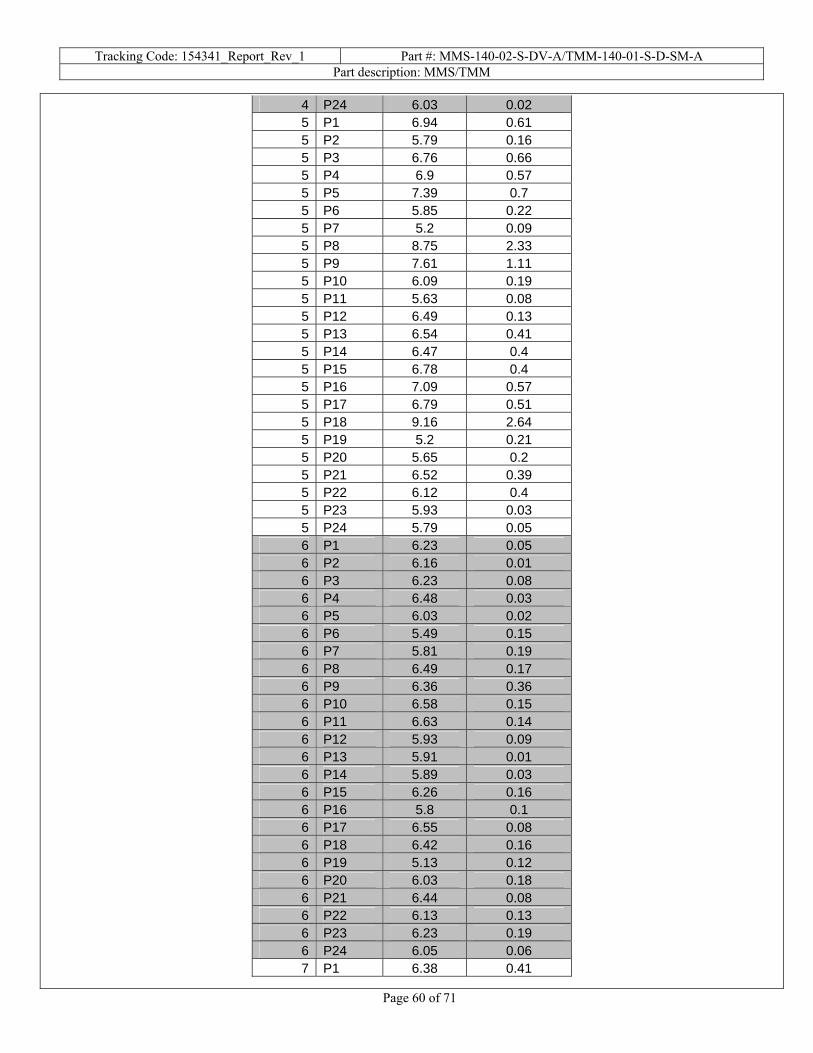
Tracking Code: 154341_Report_Rev_1 Part #: MMS-140-02-S-DV-A/TMM-140-01-S-D-SM-A Part description: MMS/TMM
Page 60 of 71
4 P24 6.03 0.02 5 P1 6.94 0.61 5 P2 5.79 0.16 5 P3 6.76 0.66 5 P4 6.9 0.57 5 P5 7.39 0.7 5 P6 5.85 0.22 5 P7 5.2 0.09 5 P8 8.75 2.33 5 P9 7.61 1.11 5 P10 6.09 0.19 5 P11 5.63 0.08 5 P12 6.49 0.13 5 P13 6.54 0.41 5 P14 6.47 0.4 5 P15 6.78 0.4 5 P16 7.09 0.57 5 P17 6.79 0.51 5 P18 9.16 2.64 5 P19 5.2 0.21 5 P20 5.65 0.2 5 P21 6.52 0.39 5 P22 6.12 0.4 5 P23 5.93 0.03 5 P24 5.79 0.05 6 P1 6.23 0.05 6 P2 6.16 0.01 6 P3 6.23 0.08 6 P4 6.48 0.03 6 P5 6.03 0.02 6 P6 5.49 0.15 6 P7 5.81 0.19 6 P8 6.49 0.17 6 P9 6.36 0.36 6 P10 6.58 0.15 6 P11 6.63 0.14 6 P12 5.93 0.09 6 P13 5.91 0.01 6 P14 5.89 0.03 6 P15 6.26 0.16 6 P16 5.8 0.1 6 P17 6.55 0.08 6 P18 6.42 0.16 6 P19 5.13 0.12 6 P20 6.03 0.18 6 P21 6.44 0.08 6 P22 6.13 0.13 6 P23 6.23 0.19 6 P24 6.05 0.06 7 P1 6.38 0.41

Tracking Code: 154341_Report_Rev_1 Part #: MMS-140-02-S-DV-A/TMM-140-01-S-D-SM-A Part description: MMS/TMM
Page 61 of 71
7 P2 6.34 0.02 7 P3 6.55 0.45 7 P4 6.37 0.15 7 P5 6.12 0.17 7 P6 5.5 0.19 7 P7 5.71 0.07 7 P8 7.86 1.05 7 P9 9.35 2.37 7 P10 7.1 0.63 7 P11 6.79 0.41 7 P12 6.72 0.34 7 P13 6.15 0.03 7 P14 6.67 0.23 7 P15 6.29 0.35 7 P16 6.26 0.3 7 P17 6.19 0.37 7 P18 6.5 0.25 7 P19 5.64 0.02 7 P20 5.73 0.28 7 P21 6.67 0.61 7 P22 6.15 0.07 7 P23 6.43 0.38 7 P24 6.83 0.54 8 P1 5.77 0.22 8 P2 6.63 0.58 8 P3 6.89 0.48 8 P4 5.32 0.47 8 P5 5.82 0.26 8 P6 5.45 0.4 8 P7 6.13 0.18 8 P8 6.98 0.23 8 P9 7.39 0.72 8 P10 6.49 0.6 8 P11 7.21 0.84 8 P12 5.98 0.15 8 P13 5.75 0.18 8 P14 6.65 0.55 8 P15 6.49 0.12 8 P16 6.35 0.27 8 P17 7.04 0.26 8 P18 7.1 0.05 8 P19 5.56 0.6 8 P20 5.8 0.16 8 P21 6.51 0.29 8 P22 5.94 0.19 8 P23 6.25 0.14 8 P24 5.9 0.13

Tracking Code: 154341_Report_Rev_1 Part #: MMS-140-02-S-DV-A/TMM-140-01-S-D-SM-A Part description: MMS/TMM
Page 62 of 71
DATA Continued LLCR Gas Tight
mOhm values Actual Delta
Board Position Initial Gas Tight 1 P1 6.42 0.04 1 P2 7.33 0.3 1 P3 5.95 0.11 1 P4 6.9 0.03 1 P5 5.91 0.16 1 P6 5.61 0.27 1 P7 5.52 0.1 1 P8 6.16 0.08 1 P9 6.4 0.01 1 P10 6.41 0.07 1 P11 6.44 0.1 1 P12 6.17 0.06 1 P13 6.8 0.03 1 P14 6.43 0.01 1 P15 6.61 0 1 P16 5.94 0.01 1 P17 6.2 0.04 1 P18 6.65 0.03 1 P19 6.34 0.03 1 P20 5.51 0.02 1 P21 6.9 0.23 1 P22 6.86 0.05 1 P23 7.3 0.05 1 P24 6.61 0.04 2 P1 6.86 0.06 2 P2 7.07 0.04 2 P3 6.85 0.04 2 P4 7.02 0.12 2 P5 6.68 0.07 2 P6 5.87 0.06 2 P7 5.92 0.09 2 P8 6.63 0.01 2 P9 6.62 0.11 2 P10 6.62 0.16 2 P11 6.77 0.09 2 P12 6.83 0.06 2 P13 6.32 0.03 2 P14 6.35 0.07 2 P15 6.32 0 2 P16 6.23 0.04 2 P17 6.56 0.06 2 P18 6.52 0.02 2 P19 5.83 0.19 2 P20 6.5 0.15 2 P21 7.08 0.05

Tracking Code: 154341_Report_Rev_1 Part #: MMS-140-02-S-DV-A/TMM-140-01-S-D-SM-A Part description: MMS/TMM
Page 63 of 71
2 P22 7.07 0.05 2 P23 7.62 0.13 2 P24 7.3 0.09 3 P1 6.22 0.1 3 P2 6.18 0.12 3 P3 6.56 0.06 3 P4 6.57 0.03 3 P5 6.17 0.13 3 P6 5.93 0.06 3 P7 5.94 0.1 3 P8 6.8 0.07 3 P9 6.41 0.03 3 P10 6.41 0.06 3 P11 6.32 0.15 3 P12 6.63 0.02 3 P13 5.92 0.04 3 P14 5.93 0.01 3 P15 6.11 0.06 3 P16 5.9 0.1 3 P17 6.16 0 3 P18 6.24 0.1 3 P19 5.64 0.01 3 P20 7.01 0.28 3 P21 6.28 0.07 3 P22 6.66 0.04 3 P23 6.55 0.03 3 P24 6.03 0.35 4 P1 6.05 0.01 4 P2 6.07 0.05 4 P3 6.22 0.06 4 P4 6.16 0.1 4 P5 5.96 0 4 P6 5.95 0.18 4 P7 5.47 0.13 4 P8 6.4 0.04 4 P9 5.89 0.02 4 P10 5.98 0.01 4 P11 6.15 0.01 4 P12 6.16 0.04 4 P13 6.53 0.03 4 P14 6.2 0.04 4 P15 5.81 0.04 4 P16 6.45 0.01 4 P17 5.93 0.01 4 P18 6.51 0 4 P19 5.86 0.19 4 P20 6.13 0.1 4 P21 6.03 0.01 4 P22 6.13 0.07 4 P23 6.09 0.03

Tracking Code: 154341_Report_Rev_1 Part #: MMS-140-02-S-DV-A/TMM-140-01-S-D-SM-A Part description: MMS/TMM
Page 64 of 71
4 P24 6.14 0.04 5 P1 6.17 0.08 5 P2 6.14 0.09 5 P3 6.15 0.15 5 P4 6.2 0.08 5 P5 5.87 0.11 5 P6 6.11 0.04 5 P7 5.9 0.08 5 P8 6.66 0.06 5 P9 6.67 0.08 5 P10 6.45 0.17 5 P11 7.14 0.06 5 P12 6.58 0.02 5 P13 6.35 0.11 5 P14 6.05 0.05 5 P15 6.08 0.1 5 P16 6.27 0.03 5 P17 6.19 0.12 5 P18 6.65 0.12 5 P19 5.54 0.1 5 P20 5.73 0.07 5 P21 5.95 0.11 5 P22 5.83 0.08 5 P23 6.37 0.04 5 P24 6.95 0.12 6 P1 6.16 0.18 6 P2 6.01 0.07 6 P3 7.27 0.13 6 P4 6.24 0.1 6 P5 6.11 0.23 6 P6 6.15 0.19 6 P7 6.34 0.04 6 P8 6.2 0.16 6 P9 6.23 0.06 6 P10 6.71 0.06 6 P11 5.94 0.12 6 P12 6.49 0.17 6 P13 6.05 0.11 6 P14 6.15 0.1 6 P15 6.01 0.05 6 P16 6.04 0.05 6 P17 5.88 0.12 6 P18 6.17 0.04 6 P19 5.45 0.1 6 P20 5.83 0.22 6 P21 6.03 0.05 6 P22 5.84 0.08 6 P23 6 0.03 6 P24 6.32 0.11 7 P1 5.66 0.07

Tracking Code: 154341_Report_Rev_1 Part #: MMS-140-02-S-DV-A/TMM-140-01-S-D-SM-A Part description: MMS/TMM
Page 65 of 71
7 P2 5.93 0.11 7 P3 6.41 0.09 7 P4 6.49 0.13 7 P5 6.2 0.09 7 P6 7.91 0.14 7 P7 5.89 0.12 7 P8 6.46 0.01 7 P9 6.1 0.02 7 P10 6.02 0.11 7 P11 6.18 0.06 7 P12 6.28 0.02 7 P13 6.39 0.17 7 P14 6.18 0.05 7 P15 5.86 0.02 7 P16 6 0.03 7 P17 5.67 0.03 7 P18 6.73 0.05 7 P19 5.71 0.15 7 P20 5.77 0.12 7 P21 6.27 0.05 7 P22 6.46 0.06 7 P23 6.37 0.05 7 P24 6.7 0.1 8 P1 7.26 0.06 8 P2 6.27 0.09 8 P3 6.81 0.07 8 P4 6.3 0 8 P5 6.58 0.17 8 P6 6.04 0.01 8 P7 5.86 0.01 8 P8 6.24 0.04 8 P9 6.14 0.07 8 P10 6.46 0.03 8 P11 6.09 0 8 P12 6.75 0 8 P13 6.91 0.01 8 P14 6.53 0.01 8 P15 6.33 0.06 8 P16 6.48 0.03 8 P17 6.53 0.05 8 P18 6.5 0.09 8 P19 5.33 0.09 8 P20 5.82 0.22 8 P21 7.3 0.14 8 P22 7.64 0.19 8 P23 6.52 0.1 8 P24 7.02 0.03

Tracking Code: 154341_Report_Rev_1 Part #: MMS-140-02-S-DV-A/TMM-140-01-S-D-SM-A Part description: MMS/TMM
Page 66 of 71
Data Continued LLCR S&V:
mOhm values Actual Delta Board Position Initial Shock / Vibe
1 P1 6.79 0.12 1 P2 7.31 0.2 1 P3 9.17 1.37 1 P4 7.83 0.68 1 P5 7.21 0.96 1 P6 5.97 0.47 1 P7 6.14 0.83 1 P8 6.77 0.17 1 P9 6.89 1.05 1 P10 7.67 0.35 1 P11 8.05 0.67 1 P12 7.31 0.36 1 P13 6.68 0.04 1 P14 7.06 0.08 1 P15 6.62 0.02 1 P16 7.36 0.6 1 P17 7.26 0.82 1 P18 7.51 0.89 1 P19 6.53 1.13 1 P20 6.16 0.21 1 P21 7.12 0.6 1 P22 7.25 0.3 1 P23 8.25 0.49 1 P24 7.15 0.06 2 P1 8.71 1.8 2 P2 7.05 0.01 2 P3 6.42 0.1 2 P4 6.57 0.42 2 P5 7.3 1.94 2 P6 5.07 0.32 2 P7 5.45 0.04 2 P8 6.92 0.2 2 P9 6.37 0.09 2 P10 6.06 1.23 2 P11 5.6 1.77 2 P12 5.77 0.74 2 P13 6.3 1.03 2 P14 5.75 0.22 2 P15 6.03 0.34 2 P16 6.74 0.29 2 P17 5.96 0.39 2 P18 6.75 0.34 2 P19 5.64 0.28 2 P20 5.52 0.77 2 P21 6.11 0.19 2 P22 6.16 0.24

Tracking Code: 154341_Report_Rev_1 Part #: MMS-140-02-S-DV-A/TMM-140-01-S-D-SM-A Part description: MMS/TMM
Page 67 of 71
2 P23 5.78 0.4 2 P24 6.56 0.31 3 P1 6.2 0 3 P2 6.38 0.03 3 P3 6.16 0.1 3 P4 6.07 0.11 3 P5 6.23 0.17 3 P6 5.89 0.34 3 P7 5.78 0.68 3 P8 6.61 0.03 3 P9 6.06 0.05 3 P10 6.33 0.14 3 P11 6.25 0.12 3 P12 6.5 0.16 3 P13 6.31 0.15 3 P14 5.99 0.13 3 P15 6.09 0.11 3 P16 6.98 0.29 3 P17 6.49 0.09 3 P18 7.23 0.33 3 P19 6.08 0.81 3 P20 6.34 0.75 3 P21 6.51 0.02 3 P22 6.29 0.15 3 P23 6.36 0.07 3 P24 7.12 0.2 4 P1 6.49 0.76 4 P2 6.2 0.26 4 P3 6.51 0.04 4 P4 6.85 0.02 4 P5 6.83 0.4 4 P6 5.1 0.45 4 P7 6.9 1.69 4 P8 7.21 0.68 4 P9 7 0.15 4 P10 6.11 0.87 4 P11 7 0.31 4 P12 6.48 0.75 4 P13 7.3 0.58 4 P14 7.26 0.2 4 P15 6.92 0.14 4 P16 6.82 0.1 4 P17 6.48 0.22 4 P18 6.77 0.09 4 P19 6.14 0.74 4 P20 5.72 0.77 4 P21 7.35 0.33 4 P22 6.67 0.34 4 P23 6.59 0.4 4 P24 6.79 2.24

Tracking Code: 154341_Report_Rev_1 Part #: MMS-140-02-S-DV-A/TMM-140-01-S-D-SM-A Part description: MMS/TMM
Page 68 of 71
5 P1 6.19 0.26 5 P2 6.28 0.37 5 P3 6.99 0.15 5 P4 8.43 0.19 5 P5 7.04 0.69 5 P6 5.79 0.13 5 P7 5.78 0.23 5 P8 6.95 0.69 5 P9 7.69 1.05 5 P10 6.99 0.58 5 P11 6.46 0 5 P12 6.33 0.38 5 P13 6.42 0.59 5 P14 6.51 0.54 5 P15 6.73 0.42 5 P16 6.96 0.3 5 P17 6.64 0.41 5 P18 6.29 0.32 5 P19 5.18 0.05 5 P20 5.93 0.54 5 P21 6.87 0.34 5 P22 6.19 0.12 5 P23 6.76 0.3 5 P24 6.12 0.04 6 P1 6.21 0.13 6 P2 6.62 0.04 6 P3 6.74 0.62 6 P4 6.34 0.37 6 P5 6.09 0.04 6 P6 5.81 0.71 6 P7 5.94 0.98 6 P8 6.25 0.45 6 P9 6.93 0.96 6 P10 8.08 0.79 6 P11 6.08 0.14 6 P12 6.39 0.26 6 P13 5.88 0.04 6 P14 6.16 0.13 6 P15 8.42 1.08 6 P16 6.55 0.32 6 P17 6.77 0.56 6 P18 6.33 0.18 6 P19 6.17 1.01 6 P20 6.44 0.83 6 P21 7.25 0.67 6 P22 6.48 0.15 6 P23 6.57 0.14 6 P24 7.1 0.18 7 P1 7.32 0.21 7 P2 6.44 0.08

Tracking Code: 154341_Report_Rev_1 Part #: MMS-140-02-S-DV-A/TMM-140-01-S-D-SM-A Part description: MMS/TMM
Page 69 of 71
7 P3 6.23 0 7 P4 6.39 0.37 7 P5 5.88 0.26 7 P6 5.26 0.27 7 P7 6.04 0.55 7 P8 6.99 0.88 7 P9 7.19 1.03 7 P10 6.17 0.17 7 P11 6.36 0.3 7 P12 6.76 0.19 7 P13 5.91 0.45 7 P14 6.53 0.1 7 P15 6.72 0.87 7 P16 6.2 0.61 7 P17 6.54 0.64 7 P18 6.96 1.09 7 P19 5.89 0.89 7 P20 5.65 0.45 7 P21 6.38 0.46 7 P22 6.46 0.05 7 P23 6.06 0.36 7 P24 6.24 0.67 8 P1 6.41 0.32 8 P2 6.41 0.03 8 P3 6.45 0.43 8 P4 6.8 0.79 8 P5 6.06 0.35 8 P6 5.55 0.49 8 P7 5.87 0.75 8 P8 6.32 0.53 8 P9 6.5 0.5 8 P10 6.24 0.28 8 P11 6.35 0.24 8 P12 6.1 0.25 8 P13 6.17 0.2 8 P14 7.16 0.21 8 P15 6.43 0.26 8 P16 6.3 0.37 8 P17 7.26 1.13 8 P18 6.7 0.62 8 P19 6.26 1.01 8 P20 6.91 1.36 8 P21 6.57 0.61 8 P22 6.74 0.35 8 P23 5.91 0.07 8 P24 5.9 0.08

Tracking Code: 154341_Report_Rev_1 Part #: MMS-140-02-S-DV-A/TMM-140-01-S-D-SM-A Part description: MMS/TMM
Page 70 of 71
EQUIPMENT AND CALIBRATION SCHEDULES
Equipment #: MO-03 Description: Micro-ohmmeter Manufacturer: Keithley Model: 580 Serial #: 297288 Accuracy: Last Cal: 2011-8-06, Next Cal: 2012-8-05 Equipment #: TCT-01 Description: Normal force analyzer Manufacturer: Mecmesin Multitester Model: Mecmesin Multitester 2.5-i Serial #: 08-1049-04 Accuracy: Last Cal: 2011-4-28, Next Cal: 2012-4-27 Equipment #: OV-01 Description: Oven Manufacturer: Huida Model: CS101-1E Serial #: CS101-1E-B Accuracy: Last Cal: 2010-12-14, Next Cal: 2011-12-13 Equipment #: THC-01 Description: Humidity transmitter Manufacturer: Thermtron Model: HMM30C Serial #: D0240037 Accuracy: Last Cal: 2011-3-3, Next Cal: 2012-3-2 Equipment #: OGP-01 Description: Video measurement system Manufacturer: OGP Model: SMARTSCOPE FLASH 200 Serial #: SVW2003632 Accuracy: Last Cal: 2011-6-10, Next Cal: 2012-6-9 Equipment #: MO-01 Description: Micro-ohmmeter Manufacturer: Keithley Model: 2700 Serial #: 1199807 Accuracy: Last Cal: 2011-4-28, Next Cal: 2012-4-27

Tracking Code: 154341_Report_Rev_1 Part #: MMS-140-02-S-DV-A/TMM-140-01-S-D-SM-A Part description: MMS/TMM
Page 71 of 71
EQUIPMENT AND CALIBRATION SCHEDULES
Equipment #: PS-01 Description: Power Supply Manufacturer: Agilent Model: 6031A Serial #: MY41000982 Accuracy: Last Cal: 2011-4-28, Next Cal: 2012-4-27 Equipment #: TSC-01 Description: Thermal Shock transmitter Manufacturer: Keithley Model: 10-VT14994 Serial #: VTS-3-6-6-SC/AC Accuracy: Last Cal: 2011-11-1, Next Cal: 2012-11-1 Equipment #: ACLM-01 Description: Accelerometer Manufacturer: PCB Piezotronics Model: 352C03 Serial #: 115819 Accuracy: See Manual … Last Cal: 2011-07-9, Next Cal: 2012-7-9 Equipment #: ED-03 Description: Event Detector Manufacturer: Analysis Tech Model: 32EHD Serial #: 1100604 Accuracy: See Manual … Last Cal: 2011-06-4, Next Cal: 2012-06-4