Design, Producing and Testing of 12-Step Three-Phase ...
14
Elektrik Elektronik Mühendisliği / Electrical Electronic Engineering DOI: 10.21597/jist.622386 Araştırma Makalesi / Research Article Iğdır Üniversitesi Fen Bilimleri Enstitüsü Dergisi, 10(2): 956-969, 2020 Journal of the Institute of Science and Technology, 10(2): 956-969, 2020 ISSN: 2146-0574, eISSN: 2536-4618 956 Design, Producing and Testing of 12-Step Three-Phase Voltage Source Inverter with Flexible Independent PWM Current Control for Brushless Direct Current Motor Mehmet Cihat ÖZGENEL 1* ABSTRACT: Brushless motors are used in wide areas in the industrial and domestic applications owing to their superior advantages over other type electric motors such as induction and brushed direct current motors. Owing to fact that the brushless direct current motors and their drivers are cheaper and easier to design than drives of permanent magnet synchronous motors, brushless direct current motors are preferred a large application areas. But BLDC motor drivers are still run classical three-phase six- step inverter. Because of that the BLDC motors are run classical three-phase six-step inverter, the BLDC motor does not show its real dynamic performance. If BLDC motor is run via 12-step inverter, it gives a better dynamic performance than that of six-step inverter. The aim of this study, to manufacture 12-step inverter which controls phase currents using pulse width modulation (PWM) technique and to analyze the dynamic performance of BLDC motor running under purposed 12-step inverter. In the 12-step inverter, two or three transistors are on conduction mode at each time interval alternatively and in order to keep switching losses minimum only one transistor runs PWM mode in this study. The experimental results show that purposed flexible independent PWM 12-step inverter works perfectly and this proposed inverter provides the BLDC motor generating high dynamic performance than that of six-step one. Keywords: BLDC Motor, voltage source inverter, 12-step inverter, six-step inverter, PWM current control, BLDC motor speed control. 1 Mehmet Cihat ÖZGENEL (Orcid ID: 0000-0001-5304-1488), Erzincan Binali Yildirim University, Faculty of Engineering, Department of Electrical Electronics Engineering, Erzincan, Turkey *Sorumlu Yazar/Corresponding Author: Mehmet Cihat ÖZGENEL, e -mail: [email protected] The article was presented as a summary in the International Academic Research Congress on 30 October-03 November 2018 in Alanya / Antalya Geliş tarihi / Received: 19-09-2019 Kabul tarihi / Accepted: 28-12-2019
Transcript of Design, Producing and Testing of 12-Step Three-Phase ...

Elektrik Elektronik Mühendisliği / Electrical Electronic Engineering DOI: 10.21597/jist.622386
Araştırma Makalesi / Research Article
Iğdır Üniversitesi Fen Bilimleri Enstitüsü Dergisi, 10(2): 956-969, 2020
Journal of the Institute of Science and Technology, 10(2): 956-969, 2020
ISSN: 2146-0574, eISSN: 2536-4618
956
Design, Producing and Testing of 12-Step Three-Phase Voltage Source Inverter with
Flexible Independent PWM Current Control for Brushless Direct Current Motor
Mehmet Cihat ÖZGENEL1*
ABSTRACT: Brushless motors are used in wide areas in the industrial and domestic applications
owing to their superior advantages over other type electric motors such as induction and brushed direct
current motors. Owing to fact that the brushless direct current motors and their drivers are cheaper and
easier to design than drives of permanent magnet synchronous motors, brushless direct current motors
are preferred a large application areas. But BLDC motor drivers are still run classical three-phase six-
step inverter. Because of that the BLDC motors are run classical three-phase six-step inverter, the
BLDC motor does not show its real dynamic performance. If BLDC motor is run via 12-step inverter,
it gives a better dynamic performance than that of six-step inverter. The aim of this study, to
manufacture 12-step inverter which controls phase currents using pulse width modulation (PWM)
technique and to analyze the dynamic performance of BLDC motor running under purposed 12-step
inverter. In the 12-step inverter, two or three transistors are on conduction mode at each time interval
alternatively and in order to keep switching losses minimum only one transistor runs PWM mode in
this study. The experimental results show that purposed flexible independent PWM 12-step inverter
works perfectly and this proposed inverter provides the BLDC motor generating high dynamic
performance than that of six-step one.
Keywords: BLDC Motor, voltage source inverter, 12-step inverter, six-step inverter, PWM current
control, BLDC motor speed control.
1 Mehmet Cihat ÖZGENEL (Orcid ID: 0000-0001-5304-1488), Erzincan Binali Yildirim University, Faculty of
Engineering, Department of Electrical Electronics Engineering, Erzincan, Turkey
*Sorumlu Yazar/Corresponding Author: Mehmet Cihat ÖZGENEL, e-mail: [email protected]
The article was presented as a summary in the International Academic Research Congress on 30 October-03 November
2018 in Alanya / Antalya
Geliş tarihi / Received: 19-09-2019
Kabul tarihi / Accepted: 28-12-2019

Mehmet Cihat ÖZGENEL 10(2): 956-969, 2020
Design, Producing and Testing of 12-Step Three-Phase Voltage Source Inverter with Flexible Independent PWM
Current Control for Brushless Direct Current Motor
957
INTRODUCTION
As it is well known that some electric motors run from power supply directly such as induction,
brushed small power DC motors and universal motors, but some of electric motors need drivers to run
such as PMSM, BLDC motor and stepper motors. If the induction motors, brushed small power DC
motors and universal motors are used applications requires variable speed or torque control, these
motors must also be used with the drivers. In other words, if speed and torque control is required, all
electric motors need drivers. These drivers are often referred to as inverters. Inverters are power
electronics circuits that convert direct current to alternating current. They are used in numerous
applications such as switching power supplies in electronics devices, motor drivers and DC high
voltage transportation (Mangroliya et al., 2013; Shah et al., 2013). Furthermore inverters are used in
solar and wind energy systems. In generally inverters are used a large number of variable frequency
drives for AC motor control (Saied et al., 2006; Mahsewari et al., 2015). AC motors are largely
induction motors, synchronous motors universal motors and brushless motors. These motors require a
driver not only running but also controlling speed and torque control of motor. Among the AC motors,
it is seen that the brushless motors have superior features. Brushless motors are used in wide areas in
the industrial and domestic applications owing to their superior advantages over other type electric
motors such as induction and brushed direct current motors. Some advantages of brushless motors are;
they have small size compared to AC motors for the same power, good linear torque-speed characteristic, easy
torque and speed control, noiseless operating, high efficiency, fast dynamic response (Ozgenel, 2017).
Brushless motors are divided into two main groups according to the shape of the back
electromotive force in the phase windings. The first one is trapezoidal back electro motive force in the
phase winding that is called brushless direct current motor and the second one is sinusoidal back
electro motive force in the phase winding that is called permanent magnet synchronous motor
(PMSM). While permanent magnet synchronous motors phase windings are fed by sinusoidal current,
permanent magnet direct current motors phase windings are fed by trapezoidal currents via three-phase
inverter (Ozgenel, 2017). Both PMSM and BLDC motors are need rotor position information to be
made commutation properly. In order to feed to PMSM phase windings with sinusoidal current, rotor
position of PMSM is sensed by sinusoidal encoder, incremental encoder or resolver with high accuracy
which is relatively expensive. Since BLDC motor windings are fed with trapezoidal current, BLDC
motor rotor position is sensed roughly with 60-electrical degree interval by Hall-effect magnetic
sensors which are low cost. Because of that the BLDC motors are run classical three-phase six-step
inverter, the BLDC motor does not show its dynamic potential performance. In six-step BLDC motor
drives, only any two phases of three phase-windings are active and one phase winding is inactive at a
step of six-step (Ahmed, 2015). The empty phase does not contribute to the production speed and
torque (Ozgenel, 2018). In the BLDC motor, which uses a six-step inverter, the utilization rate of the
phase windings is 66 percent (ST Microelectronics, 2006; Ozgenel, 2018). In order to get higher
performance from the same BLDC motor, it is necessary to increase the duration of the current passing
through the phase windings of the BLDC motor. This is easily achieved by employing 12-step inverter.
If the BLDC motor runs with a 12-step inverter, it will produce more torque and speed than the BLDC
motor runs in the 6-step inverter. Because in the 12-step inverter three phases are active at the same time and
contribute to the torque and speed production, BLDC motor generates more speed and torque. The rate of
utilization of phase winding is 83 percent in BLDC motor which works with 12 step inverter (Ozgenel, 2018).

Mehmet Cihat ÖZGENEL 10(2): 956-969, 2020
Design, Producing and Testing of 12-Step Three-Phase Voltage Source Inverter with Flexible Independent PWM
Current Control for Brushless Direct Current Motor
958
In this study, both six-step and twelve-step inverter with independent PWM current control are
designed and manufactured in order to compare effect on the BLDC motor performance. Flexible
independent PWM current control scheme is used in 12-step inverter.
MATERIALS AND METHODS
Driving Of Bldc Motors
Figure 1 is depicted a conventional BLDC motor driver system. A typical BLDC driver system
is consist of rotor position sensors, inverter, commutation logic circuitry, inverter transistor driver and
BLDC motor. Commutation logic circuitry generates transistor gate signals according to rotor position
and adjusts PWM duty cycle according to speed demand. When the rotor rotates, position sensors (SA
SB and SC) generate logic 1 and logic 0. This rotor position information is used to energize motor
phase windings via power transistors. Inverter converts DC voltage into rectangular alternate voltage
for BLDC motor phase windings. Thus, BLDC motor runs and position signals are changed with the
changing rotor position and commutation is made at the each 60-electrical degree. While commutation
is done automatically in brushed DC motors with the help of collector and brushes but it is done
electronically in BLDC motors. Commutation is the change of direction of current passing through
motor phase windings according to rotor position.
In brushless AC motors, the rotor position information must be detected by a position sensor in
order to energize phase windings according to rotor position. This position sensor is generally Hall-
effect magnetic sensor in BLDC motors (Ozgenel, 2017). Hall-effect sensors are placed on the stator
by 120-electrical degree apart from each other. The rotor position is detected by Hall-effect sensors by
60-electrical degree interval. Rotor position information is used to commutate BLDC motor phase
windings. Owing to fact that the rotor position is detected every 60-electrical degree, one electrical
period occurs in six-step. Thus design of six-step inverter is easy and less complicated. Numerous
commercial manufacturers are produced chips dedicated six-step BLDC motor driver (Ohm and
Oleksuk, 2002). BLDC motors are currently being operated with 6-step inverters. As it is seen easily
from Table 1, in six-step driver, two transistors are conduction mode and one phase winding is
connected to positive terminal of DC source and one phase winding is connected to negative terminal
of DC source at each step.
Figure 1. Typical six-step BLDC motor driving system
IGB
T/M
OS
FE
T D
RIV
ER
+V
BLDC
SC
AB
C
T1
T2
T3
T4
T5
T6
speed
demand
co
mm
uta
tio
n lo
gic
an
d P
WM
ge
ne
ratin
g
rotor position feedback
SA
SB
VSI inverter

Mehmet Cihat ÖZGENEL 10(2): 956-969, 2020
Design, Producing and Testing of 12-Step Three-Phase Voltage Source Inverter with Flexible Independent PWM
Current Control for Brushless Direct Current Motor
959
After six-step is completed, it is returned to first step. So, one period is completed. If Table 1 is
examined, two-phase winding is energized at each step and pair of phase windings is changed at each
step, each step is 60 electrical degrees. On Table 1 in the first step, A-phase winding is connected to
positive terminal of DC source and C-phase winding is connected negative terminal of DC source. In
this step A and C- phase windings produces torque and velocity. In the second step, while C- phase is
still connected to negative terminal of DC source, C-phase winding is changed its pair of phase
winding from A-phase to B-phase.
Table 1. Status of inverter transistors, energized phase windings according to rotor position switches in six-step inverter
Step
Status of inverter transistors
Energized
phase
windings
Position swithes
T2 T5 T6 T3 T4 T1 SA SB SC
1 On Off FREE FREE Off On A+, C- 1 0 0
2 On Off Off On FREE FREE B+, C- 1 1 0
3 FREE FREE Off On On Off B+, A- 0 1 0
4 Off On FREE FREE On Off C+, A- 0 1 1
5 Off On On Off FREE FRE C+, B- 0 0 1
6 FREE FREE On Off Off On A+, B- 1 0 1
In the third step, his time B-phase winding is the same, A-phase is replaced by C-phase. The six-
step inverter operation continues in this way. Due to fact that two phase’s windings should be
energized at each step in six-step inverter, and then two switches should conduct at any step (Chen et
al., 2009). As it is known well, due to fact that pulse width modulation technique reduces power losses
and having greater efficiency in the system is commonly used in DC-DC converters and motor speed
control applications (Bolloju, 2007). The output voltage can be easily changed by adjusted conduct time of
power switch. The average voltage of PWM DC-DC convertor is expressed;
𝑉𝑜 = 𝑉𝐷𝐶𝑡𝑜𝑛
𝑇 (1)
Where, 𝑉𝑜 is the PWM converter output voltage, 𝑉𝐷𝐶 is the input voltage, 𝑡𝑜𝑛 is conduct time of power
transistor and T is the period of PWM frequency.
Speed Control of Bldc Motor
Because the speed of the BLDC motor depends on the amplitude of the voltage applied to the phase
windings, the speed control of the BLDC motor is implemented by changing the amplitude of the voltage
applied to the phase windings as it is in direct current motors with brushed (Varghese et al., 2014). The
amplitude of the voltage applied to the phase windings can be easily changed using the pulse width
modulation technique (PWM). PWM voltage control scheme is the most used speed control technique
for BLDC motors (Pindoriya et al., 2014). In PWM technique, the amplitude of the phase voltage is
adjusted by changing the duration of the pulse using power transistors in inverter. There are two main
ways of power transistor switching schemes in the inverter with PWM signals: independent and
complementary modes (Breji et al., 2006). In the independent PWM mode, inverter upper (T1, T3 and
T5) or lower (T4, T6 and T2) transistors are run in PWM mode. This mode is relatively simple to
control BLDC motor phase voltage. In the complementary mode, the power transistors in one phase
inverter leg for example T1 and T4 are run complementary. Implementation of this scheme is
relatively complex according to independent PWM mode. In six-step inverter, two phase windings are
energized and one phase winding is free all time intervals. While two phase windings generate torque
and speed but one phase winding does not contribute generating torque and speed. Each phase winding

Mehmet Cihat ÖZGENEL 10(2): 956-969, 2020
Design, Producing and Testing of 12-Step Three-Phase Voltage Source Inverter with Flexible Independent PWM
Current Control for Brushless Direct Current Motor
960
is energized with other phase winding is free during one step interval which is equal to 60 electrical
degrees in six-step inverter. Each step interval is 60 electrical degrees. So, commutation occurs at each
60 electrical degrees.
Six-step voltage source inverter with pwm phase voltage control
The independent mode PWM voltage control method is used in six-step inverter. Many
commercial integrated circuit manufacturers produce independent PWM controlled BLDC motor pre-
driver integrated such as MC33033, LV8127T from ON Semiconductor corp., DRV8302 from Texas
Instruments corp., FCM8201 from Fairchild Semiconductor corp. is a BLDC motor inverter pre-driver
which uses complementary PWM scheme. In this proposed inverter, PWM signals are generated by
employing SG3526 high performance pulse width modulator integrated circuit from ON
Semiconductor corp. (On Semiconductor Corp., 2006). The PWM frequency is selected 20 kHz. To
obtain the output of phase voltage of six step inverter, equation (2) should use (Promthong and
Konghirun, 2013);
𝑉𝑝ℎ𝑎𝑠𝑒(120) = 0.41𝑉𝐷𝐶 (2)
Where VDC is the input DC voltage of inverter from DC supply. Equation (2) is valid when duty
cycle of PWM 100%. If duty cycle of PWM smaller than 100%, the following equation is used;
𝑉𝑝ℎ𝑎𝑠𝑒(120) = 0.41𝑉𝐷𝐶𝑡𝑜𝑛
𝑇 (3)
From Figure 2, it is seen that every time interval only two phase windings are energized. While
one phase winding is connected positive terminal of DC supply, other phase is connected to negative
terminal of DC power supply. One phase winding is free. During one period, one phase winding is
continuously non-energized. This non-energized winding is changed at each step. While in step 1, B-
phase winding is free (non-energized), in step 2, A-phase winding is non-energized and so on. Thus
only two phase windings are produced torque and speed in six-step BLDC motor drivers. Since the
speed of BLDC motor is proportional to phase winding voltage the BLDC speed is changed by
changing phase voltage using PWM technique. In Figure 2, PWM scheme is applied to T4, T6 and T2
transistors which are connected to negative terminal of DC power supply.
A twelve-step PWM voltage controlled voltage source inverter is designed and implemented. To
avoid using numerous logic gates, quite cheap and useful Arduino-Nano platform which is based
Atmega328 microchip is used. Table 2 is taken into consideration when designing this inverter. In
twelve-step inverter, one electrical period is completed at 12 steps. In order to accomplish the 12-step
inverter, rotor position should be sensed each 30-electrical degree (Babaei and Mahaei, 2011;
Promthong, 2013; Shah et al., 2013). As it is seen from Table 2, while three phase windings are active
on one step, two phase windings are active in next step. When three phase windings are active, three
power transistors in inverter are at conduction mode, when two phase windings are active two
transistors are at the conduction mode. While three transistors are in conduction mode in one step, two
transistors are in conduction mode in the next step. Switching of the power transistors continues in this way.
The output voltage of twelve-step inverter is expressed as following (Babaei and Mahaei, 2011; Promthong,
2013);
DCphase VV 44.0)150( (4)

Mehmet Cihat ÖZGENEL 10(2): 956-969, 2020
Design, Producing and Testing of 12-Step Three-Phase Voltage Source Inverter with Flexible Independent PWM
Current Control for Brushless Direct Current Motor
961
Equation (4) is valid when duty cycle of PWM 100%. If duty cycle of PWM smaller than 100%,
the following equation is used;
𝑉𝑝ℎ𝑎𝑠𝑒(150) = 0.44𝑉𝐷𝐶𝑡𝑜𝑛
𝑇 (5)
Equations (4 and 5) show that twelve-step inverter produces higher phase voltage than that of
six-step inverter. This means BLDC motor running in twelve-step inverter produces more speed than
BLDC motor which runs in six-step inverter because BLDC motor speed is proportional is directly
phase voltage.
T1 T3 T5
T4 T6 T2
T1 T3 T5
T4 T6 T2
T1 T3 T5
T4 T6 T2
T1 T3 T5
T4 T6 T2
T1 T3 T5
T4 T6 T2
T1 T3 T5
T4 T6 T2
A
BC
A
B C
A
B
C
C
C
C
A
A
A
B
B
B
free
free
free
free
freefre
e
step 2
step 3
step 1
step 4
step 5step 6
PWM PWM
PWMPWM
PWMPWM
Figure 2. Commutation sequence in six-step inverter
Table 2. Status of inverter transistors, energized phase windings and PWM mode transistors in twelve-step inverter
Step
Status of inverter transistors
Energized
phase
windings
Transistors operating in PWM
mode
T2 T5 T6 T3 T4 T1
1 Off On On Off Off On A+, C+, B- T6
2 FREE FREE On Off Off On A+, B- T6
3 On Off On Off Off On A+,B-, C- T1
4 On Off FREE FREE Off On A+, C- T1
5 On Off Off On Off On A+, B+, C- T2
6 On Off Off On FREE FREE B+, C- T2
7 On Off Off On On Off A-, B+, C- T3
8 FREE FREE Off On On Off A-, B+ T3
9 Off On Off On On Off A-, B+, C+ T4
10 Off On FREE FREE On Off A-, C+ T4
11 Off On On Off On Off A-, B-, C+ T5
12 Off On On Off FREE FREE B-, C+ T5

Mehmet Cihat ÖZGENEL 10(2): 956-969, 2020
Design, Producing and Testing of 12-Step Three-Phase Voltage Source Inverter with Flexible Independent PWM
Current Control for Brushless Direct Current Motor
962
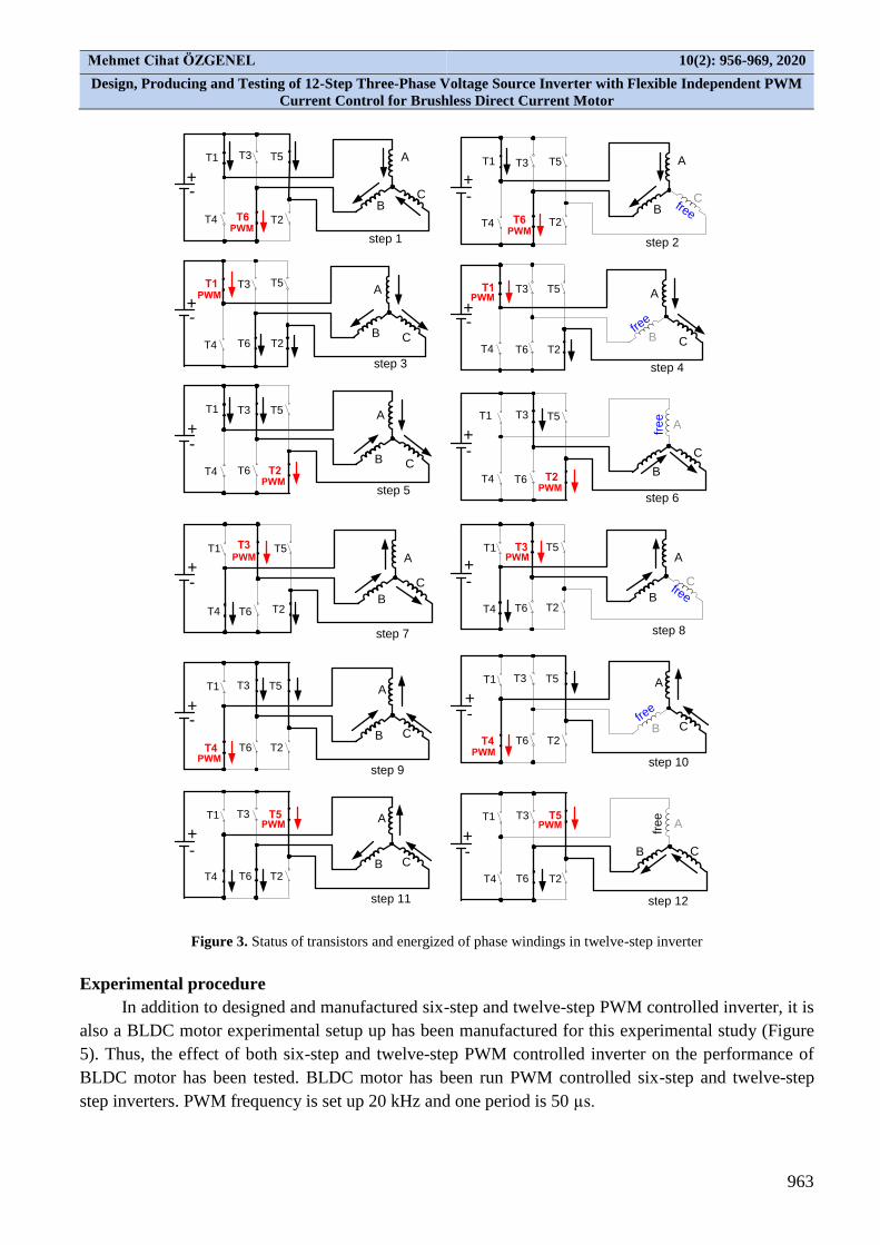
In twelve-step inverter, from Table 2, while three transistors are on conduction mode in the first
step (T1, T6 and T5) and A-phase and C-phase are connected to positive terminal of DC power source
but B-phase is connected to negative terminal of DC power source. In this step, since the sum of the
currents coming from the phases A and C pass over the B phase, so T6 transistor should run on PWM
mode. T1 and T5 transistors are kept full conduction mode in this step. Since each step is 30 degrees,
each transistor is on PWM mode during 60 electrical degrees during a period. In step 2, A-phase
winding is connected positive terminal of DC power supply B-phase winding is connected to negative
terminal of DC power supply. In this step T6 transistor is still PWM mode. In the third step, the
polarity of phases A and B remain the same while the polarity of phase C is changed. The polarity of
phase C is changed from first step to third step.
In this step, PWM transistor is changed, now T1 transistor is on PWM mode. In the fourth step,
the polarity of phases A and C remain the same, the current of phase B is cut. In the fifth step, the
direction of B phase current is changed. Transistor T1 is on PWM mode in the third and fourth step. In
the fifth step, A-phase and C-phase remain the same, the current direction of B-phase is changed and
transistor T2 runs on PWM mode. So, three-phase windings are used generating torque and velocity in
twelve step inverter and BLDC motor shows better performance. Twelve-step control scheme, the
inverter operation continues in this way. In this mode inverter, independent PWM control scheme is
used in order to reduce switching losses. In Table 2, each transistor is conduction mode during five
steps which is equal 150 electrical degrees. But each transistor is on PWM mode during two steps (60
electrical degrees) and each transistor operates in full mode in the remaining 90 degrees. To ensure this
mode of operation, a circuit has been designed to produce required gate signals as shown in Figure 4
(a) and (b). In this gate signal generating circuit, two gate signals are generated for one transistor.
These two gate signals are combined in an OR gate. In Table 2, transistor T1 is on conduction mode
(full mode) in step 1 and step 2, this time full mode output of commutation logic circuitry is active for
step 1 and step 2. In the same time the PWM output of commutation logic circuitry is inactive and
4066 bilateral switch is open. So, transistor T1 is full conduction mode. Third and fourth steps,
transistor T1 runs PWM mode this time the PWM output of commutation logic circuitry is active and
4066 bilateral switch is closed and the PWM signal is connected to OR gate but this time full mode
output of commutation logic circuitry is inactive for step 3 and step 4. Thus, transistor T1 runs PWM
mode on steps 3 and 4. When the fifth step is reached, full mode output of commutation logic circuitry
is active and the PWM output of commutation logic circuitry is inactive and 4066 bilateral switch
returns to open state. Thus, transistor T1 is runs full conduction mode for 30 electrical degrees.
At the end of the fifth step, transistor T1 is completed five steps and 150 degrees. After transistor
T1 is completed five steps, it keeps off state during five steps and it is free mode in steps 6 and 12.
Other transistors in inverter run the same way. Thus, on each step, one transistor runs PWM mode and
for PWM operation only one transistor is employed. Thus, each transistor in the inverter is operated in
PWM mode for 60 degrees and a flexible 12-step PWM controlled drive is obtained. On the other
hand, since one transistor is used in each step for PWM, the switching losses are minimized.
Mehmet Cihat ÖZGENEL 10(2): 956-969, 2020
Design, Producing and Testing of 12-Step Three-Phase Voltage Source Inverter with Flexible Independent PWM
Current Control for Brushless Direct Current Motor
963
T1
T2
T3
T4
T5
T6
T1
T2
T3
T4
T5
T6
T1 T3 T5
T4 T6 T2
T1 T3 T5
T4 T6 T2
A
BC
C
C
C
A
A
A
B
B
B
fre
e
free
step 10
step 1
T1
T2
T3
T4
T5
T6
A
BCfree
step 2
T1
T2
T3
T4
T5
T6
A
B C
step 3
T1
T2
T3
T4
T5
T6
A
B Cfre
e
step 4
PWM PWM
T1
T2
T3
T4
T5
T6
A
B C
step 5
T1
T2
T3
T4
T5
T6
A
B
C
fre
e
step 6
step 7
T1 T3 T5
T4 T6 T2
C
A
Bfree
step 8
T1 T3 T5
T4 T6 T2
C
A
B
step 9
T1 T3 T5
T4 T6 T2
C
A
B
step 12step 11
PWM PWM
PWMPWM
PWM PWM
PWMPWM
PWM PWM
+-
-
-
-
-
--
-
-
-
-
-
+
+
+
+
++
+
+
+
+
+
Figure 3. Status of transistors and energized of phase windings in twelve-step inverter
Experimental procedure
In addition to designed and manufactured six-step and twelve-step PWM controlled inverter, it is
also a BLDC motor experimental setup up has been manufactured for this experimental study (Figure
5). Thus, the effect of both six-step and twelve-step PWM controlled inverter on the performance of
BLDC motor has been tested. BLDC motor has been run PWM controlled six-step and twelve-step
step inverters. PWM frequency is set up 20 kHz and one period is 50 µs.

Mehmet Cihat ÖZGENEL 10(2): 956-969, 2020
Design, Producing and Testing of 12-Step Three-Phase Voltage Source Inverter with Flexible Independent PWM
Current Control for Brushless Direct Current Motor
964
A-phase
T1
T4
+VDC
40
66
40
66
PWM
co
mm
uta
tio
n lo
gic
2K2
2K2
rotor
position
input
speed
demand
ga
te d
rive
r
full mode
full mode
PWM
mode
PWM
PWM
(a) (b) Figure 4. Generating one phase transistors gate signals in proposed twelve-step inverter (a), structure of gate signals of A
and B phases transistors (b)
gate
signals
INVERTER
roto
r p
ositio
n fe
ed
ba
ck
speed
demand
DC bus voltage input (24 V)
DC generator
six and flexible twelve-step controller
six
step twelve
step
Figure 5. Purposed twelve-step inverter and experimental setup
Duty cycle of PWM is set up to 21 µs, 32 µs and 40 µs for both six-step and twelve-step
inverters. BLDC motor has been run for these duty cycles of PWM and motor performance is
examined. During experiments motor load is kept constant. A permanent magnet DC generator is used
as a BLDC motor load and 2.6 Ω resistive load is connected to DC generator as generator load. While
motor speed, motor current and phase voltage have been measured but motor power and torque have
been calculated using motor speed, phase current and back electromotive force (EMF). Thus, the effect
of both six and twelve-step PWM controlled inverter on the BLDC motor performance can be brought
into the open.
Table 3. BLDC Motor Parameters
Brand Rated Voltage (V)
Rated torque (mNm)
Rated speed (rpm)
Rated current (A)
Back EMF constant (V/krpm)
Shinano Kenshi 24 160 1800 2.1 2.54

Mehmet Cihat ÖZGENEL 10(2): 956-969, 2020
Design, Producing and Testing of 12-Step Three-Phase Voltage Source Inverter with Flexible Independent PWM
Current Control for Brushless Direct Current Motor
965
RESULTS AND DISCUSSION
Six-step and twelve-step PWM current controlled voltage controlled inverter (VSI’s) have been
run and tested. It was checked whether both inverters work as in theory. It is clearly seen in Figure 6(a)
that independent PWM mode works perfectly for six-step inverter. In six-step independent PWM
voltage controlled inverter, each transistor is conduction mode during two-step (120-degree). In
independent mode, transistor T1 which is connected to positive terminal of DC power supply works
full conduction mode. For negative pulse of motor current, transistor T4 is conduction mode for full
time (120-degree). In Figure 6(b), the gate signals of switching transistors in twelve-step inverter are
shown. In Figure 6(b), it is seen that gate signals are observed to be in perfect accordance with the
Table 2. As it is shown in Figure 6(b), each transistor is on full conduction mode the first 30-degree
(one step) then each transistor runs on PWM mode during 60-degree (two-step), after transistor
working on PWM mode, the transistor returns to full conduction mode for 60-degree (two-step). So
one transistor is on conduction mode during five steps, two steps of these are PWM mode and other
three modes are full conduction mode. From the tests as shown in Figure 6(b), it is clearly seen the
PWM controlled 12-step inverter intended for this study has been found to work perfectly. BLDC
motor has been run under the same load by employing six and twelve-step inverter by adjusting PWM
duty cycle various times.
(a) (b)
Figure 6. PWM waveforms; (a) six-step, (b) purposed twelve-step inverter
These duty cycles are 21 µs, 32 µs, and 40 µs. So, the effects of both inverters on BLDC motor
performance have been easily found out. Table 4 shows that power, torque and speed response of
BLDC motor according to five different duty cycles. As seen from Table 4, When BLDC motor works
in twelve-step inverter, BLDC motor generates more speed, power and torque than that of working on
six-step inverter under same load and for the same duty cycle. It is clearly seen that from the Table 4,
while duty cycle is 21 µs, The BLDC motor generates 122 mNm torque in six-step inverter and BLDC
motor generates 174 mNm for the same duty cycle in twelve-step inverter, it is also seen from Table 4
for the 21 µs, BLDC motor generates 42% more torque while working on twelve-step inverter than

Mehmet Cihat ÖZGENEL 10(2): 956-969, 2020
Design, Producing and Testing of 12-Step Three-Phase Voltage Source Inverter with Flexible Independent PWM
Current Control for Brushless Direct Current Motor
966
that of six-step one. In other duty cycles, the BLDC motor has also produced more power, speed and
torque in proposed flexible PWM controlled 12-step inverter than that of six-step one. When the
BLDC motor has been run for various duty cycles on six and twelve-step inverters, power and torque
generated by the BLDC motor has been calculated following expressions respectively (Ozgenel, 2018);
𝑃𝑠ℎ𝑎𝑓𝑡 = 𝐸𝑎. 𝐼𝑎 + 𝐸𝑏 . 𝐼𝑏 + 𝐸𝑐 + 𝐼𝑐 (6)
𝑇𝑒 =𝑃𝑠ℎ𝑎𝑓𝑡
𝜔𝑟=
𝐸𝑎.𝐼𝑎+𝐸𝑏.𝐼𝑏+𝐸𝑐.𝐼𝑐
𝜔𝑟 (7)
Where Ex is the back electromotive force of the corresponding phase in Volt, Ix is the relevant
phase current in Ampere and ωr is the angular velocity in rad/s.
The following equation has been used to determine the effects of the six and proposed 12-step PWM
controlled inverter on the torque generated by the BLDC motor (Ozgenel, 2018);
∆𝑇𝑒 =𝑇𝑒(12)−𝑇𝑒(6)
𝑇𝑒(6) (8)
Where )12(eT and )6(eT are the torques that are generated by BLDC motor when working on 12 and 6-
step PWM controlled inverter in Nm and T is the ratio of the effect of the 12-step inverter and the 6-
step inverter on the motor torque.
Table 4. Performance of BLDC motor working on six and proposed twelve–step inverter according to various duty cycles
Duty cycle
(µs)
Six-step inverter Twelve-step inverter ΔT
% Phase current
(A)
Speed
(rpm)
Shaft Power
(W)
Torque
(mNm)
Phase current
(A)
Speed
(rpm)
Shaft Power
(W)
Torque
(mNm)
21 1.5 826 10.63 122 1.96 970.8 17.72 174 42
32 2.19 1234 22 170 2.68 1470 32.54 211 24
40 2.67 1515 32.7 206 3.14 1724 44.19 244 18
BLDC motor has been run on both six and twelve-step PWM controlled inverters and motor speed and
motor phase current measured then motor power and motor torque have been calculated by yielding equations
(6) and (7). After motor torque and power have been calculated, the effect of both six and twelve-step inverters
on motor torque is calculated using equation (8). These values are given in Table 4.In this study, BLDC motor
dynamic performance is also tested for both inverters. Figure 7(a) shows that speed response of BLDC
motor according to two inverter schemes. When BLDC motor starts up with six-step inverter, the rotor
speed reaches 1305 rpm within 750 milliseconds while duty cycle is 64% (32 µs). Although the duty
cycle remains the same in 32 microseconds, BLDC motor speed reaches 1538 rpm in the same time
(750 milliseconds) when BLDC motor runs with 12-step inverter (Figure 7(a)). Thus, Figure 7(a)
shows that BLDC motor running with 12-step inverter speed response is faster than that of six-step.
In Figure 7(b) duty cycle is reduced from 32 µs to 29 µs in order to obtain the same speed
response. It is obviously seen from Figure 7(b) that BLDC motor working with 12-step inverter gives
the same speed response less duty cycle time (29 µs). Figure 7 proves that the proposed 12-step
scheme gives BLDC motor better dynamic response. Inverter phase voltages have been also calculated
and measured in order to examine the performance of generating phase voltage of proposed 12-step
inverter.

Mehmet Cihat ÖZGENEL 10(2): 956-969, 2020
Design, Producing and Testing of 12-Step Three-Phase Voltage Source Inverter with Flexible Independent PWM
Current Control for Brushless Direct Current Motor
967
(a) (b)
Figure 7. Start up of BLDC motor when duty cycle 64% (32 µs) for both inverters (a), reducing the duty cycle from 32 µs
to 29 µs to obtain the same dynamic performance in 12-step inverter (b)
Table 5. Phase voltages according to duty cycles for both inverters
DC bus Voltage
(V)
Duty cycle
(5)
Transistor
conduction time (µs)
Phase voltages(V)
Six-step inverter Twelve-step inverter
calculated measured calculated measured
24 42 21 4.02 4.05 4.43 4.33
24 64 32 6.14 5.85 6.75 6.63
24 80 40 7.68 7.27 8.44 8.35
Table 5 shows that proposed flexible PWM 12-step inverter produces phase voltage in
accordance with the equation (5). Calculated phase voltages and measured phase voltages are very
close to each other. The BLDC motor phase currents are also recorded.
(a) (b) Figure 8. Phase currents of BLDC motor on both six and proposed 12-step drivers
Figure 8 shows that one phase currents when the duty cycle is 32 µs. In Figure 8(a) while BLDC
motor phase current is a typical six-step inverter phase current, 12-step inverter phase current is closely
sinusoidal current. Sinusoidal phase current ensures to BLDC motor some advantages such as smooth
operation, less torque ripple, fewer harmonic (Mahsewari et al., 2015). PWM frequency 20 kHz has
been selected in this study since many inverter pre-driver chip producers use 20 kHz PWM frequency.
Thus one period is 50 µs.
CONCLUSIONS
Proposed flexible PWM controlled 12-step voltage source inverter intended for this study has
been found to work perfectly as it is seen from Figure 6(b). It is seen that Figure 6(b) is fully
compatible with the Table 2. This experimental study shows that BLDC motor gives satisfactorily
dynamic response when BLDC motor employing on purposed twelve-step flexible PWM controlled
Mehmet Cihat ÖZGENEL 10(2): 956-969, 2020
Design, Producing and Testing of 12-Step Three-Phase Voltage Source Inverter with Flexible Independent PWM
Current Control for Brushless Direct Current Motor
968
inverter as it is shown in Table 4 and Figure 7. In Table 4, when duty cycle is 21 microseconds, the
BLDC motor running in twelve-step inverter has generated more 42% torque than that of running in
six-step inverter. For each duty cycle, BLDC motor has generated more torque, power and speed. As
duty cycle increases, the difference between the torques decreases. When duty cycle is 40
microsecond, the difference between of torques becomes 18%. When duty cycle is 32 microseconds,
in this time, phase current is 2.68 A in 12-step inverter, the difference between of torques is 24%. The
proposed flexible 12-step inverter allows the BLDC motor to generate more torque, power and speed.
Figure 7 shows that BLDC motor reaches to 1538 rpm when it runs with proposed inverter but it
reaches to 1305 rpm within the same time (750 ms). Thus the BLDC motor running with proposed
inverter shows fast dynamic response. Furthermore, the proposed inverter controller provides that the
BLDC motor phase currents are very close to sinusoidal current. Sinusoidal phase currents have some
advantages such as silent operation of the motor, less torque fluctuation and harmonics. BLDC motor
speed control is done easily by proposed flexible 12-step inverter.Due to fact that proposed flexible
twelve-step inverter provides the BLDC motor generating more torque, more power and fast dynamic
response, 12-step PWM controlled inverter can be used in required high performance applications such
as robotic, industrial automation applications, medical surgery, office machines, aerospace
applications, drones, solar irrigation systems and portable devices.
REFERENCES
Ahmed MA, 2015. Brushless DC Motor Speed Control Using both PI Controller and Fuzzy PI
Controller. International Journal of Computer Applications, 109 (10): 29-35.
Babaei E, Mahaei M, 2011. Improving Output Voltage of the Three Phase Six-Switch Inverters.
Telkomnika, 9 (3): 497-502.
Bolloju V, 2007. PWM Control Methods Increases Efficiency, Reliability and Extend Battery
Lifetime. Motion Application Center. International Rectifier, Bodo’s Power Systems.
Breji M, Princ M, Sustek P, 2006. BLDC Motor with Hall Sensors and Speed Closed Loop, Driven by
eTPU an MPC5554. Application Note, Freescale Semiconductor, AN3006, Rev. 1, 05/2006.,
Inc.: 1-41.
Chen Hung-Chi, Huang Chih-Kai, Tsai Tzu-Yang, 2009. BDCM Sensorless Control for Twelve-Step
Square-Wave PWM. International Conference on Power Electronics and Drive Systems (PEDS),
2-5 Nov. 2009, Taipei.
Maheswari MH, Gohil MV, Tahilramani M, 2015. Implementation of three phase 12-step VSI with
harmonics reduction. International Journal of Advance Engineering and Research Development
(IJAERD) 3: 1–6.
Mangroliya DG, Rupapara VJ, Akabari RP, Vaghela NM, 2013. An advanced three phase VSI with
1500 conduction mode using PIC 16F72. Journal of information, knowledge and research in
electrical engineering. 2 (2): 352–357.
Ohm DY, Oleksuk RJ, 2002. Influence of PWM Schemes and Commutation Methods for DC and
Brushless Motors and Drives. Drivetech, Inc. Northrop Grumman Poly-Scientific: 1-9.
ON Semiconductor Corp., 2006. SG3526 Pulse Width Modulation Control Circuit July 2006 Rev.4.
Datasheet: 1-9.
Ozgenel MC, 2017. Design, implementation, and application of 150-degree commutation VSI to
improve speed range of sensored BLDC motor. Review of Scientific Instruments 88: 095007-1-
095007-8, doi: 10.1063/1.4997613.

Mehmet Cihat ÖZGENEL 10(2): 956-969, 2020
Design, Producing and Testing of 12-Step Three-Phase Voltage Source Inverter with Flexible Independent PWM
Current Control for Brushless Direct Current Motor
969
Ozgenel MC, 2018. Increasing power and torque capability of brushless direct current motor by
employing 150-degree conduction mode controlled three-phase voltage source inverter. Review
of Scientific Instruments 89: 085002-1-085002-9. doi: 10.1063/1.5033957.
Pindoriya RM, Rajendran S, Priyesh C, 2014. Speed Control of BLDC Motor Using PWM Technique.
International Journal of Advance Engineering and Research Development (IJAERED) ETCEE.
1-6.
Promthong S, Konghirun M, 2013. Sensorless control of BLDC motor drive with 1500 conducting
mode to minimize torque ripple. International Conference on Electrical Machine and Systems,
Oct, 26-29, (ICEMS) Busan, Korea.
Saied MH, Mostafa MZ, Abdel-Moneim TM, Yousef H. A, 2006. On three-phase six-switch voltage
source inverter: A1500 conduction mode. In IEEE ISIE (IEEE, Montr´eal, Qu´ebec, Canada).
Shah A, Mangroliya D, and Vaghela N, 2013. Simulation and Analysis of an Advanced 150o
Conduction Mode for Three Phase Voltage Source Inverter. ACEEE, Proc. Of. Int. Conf. on
Emerging Trends in Engineering and Technology.
ST Microelectronics, 2006. Low cost sinusoidal control of BLDC motors with Hall sensors using
ST7FMC, AN2373 Application note: 1–13.
Varghese AJ, Roy R, Thirunavukkarasu S, 2014. Optimized Sped Control for BLDC Motor.
International Journal of Innovative Research in Science, Engineering and Technology, 3 (1).