Design Optimization of Double-array Bolted Joints in...
9
Copyright ⓒ The Korean Society for Aeronautical & Space Sciences Received: March 8, 2016 Revised: September 13, 2016 Accepted: September 19, 2016 332 http://ijass.org pISSN: 2093-274x eISSN: 2093-2480 Paper Int’l J. of Aeronautical & Space Sci. 17(3), 332–340 (2016) DOI: http://dx.doi.org/10.5139/IJASS.2016.17.3.332 Design Optimization of Double-array Bolted Joints in Cylindrical Composite Structures Myungjun Kim*, Yongha Kim** and Pyeunghwa Kim*** Graduate School of Aerospace and Mechanical Engineering, Korea Aerospace University, Goyang-si 10540, Republic of Korea Jungsun Park**** Department of Aerospace and Mechanical Engineering, Korea Aerospace University, Goyang-si 10540, Republic of Korea Abstract A design optimization is performed for the double-bolted joint in cylindrical composite structures by using a simplified analytical method. is method uses failure criteria for the major failure modes of the bolted composite joint. For the double- bolted joint with a zigzag arrangement, it is necessary to consider an interaction effect between the bolt arrays. is paper proposes another failure mode which is determined by angle and distance between two bolts in different arrays and define a failure criterion for the failure mode. The optimal design for the double-bolted joint is carried out by considering the interactive net-tension failure mode. The genetic algorithm (GA) is adopted to determine the optimized parameters; bolt spacing, edge distance, and stacking sequence of the composite laminate. A purpose of the design optimization is to maximize the burst pressure of the cylindrical structures by ensuring structural integrity. Also, a progressive failure analysis (PFA) is performed to verify the results of the optimal design for the double-bolted joint. In PFA, Hashin 3D failure criterion is used to determine the ply that would fail. A stiffness reduction model is then used to reduce the stiffness of the failed ply for the corresponding failure mode. Key words: Double-array bolted joint, Cylindrical composite structures, Optimization, Genetic algorithm (GA), Progressive failure analysis (PFA) 1. Introduction Fiber-reinforced composite materials have been widely used in aircraft and space structures because they offer advantages such as higher specific stiffness and strength, better fatigue strength and improved corrosion resistance compared to conventional materials. ese composite structures require joining structural components. So, there are many joining systems to connect composite parts in aerospace structures. e structural integrity of composite structures is often determined by the strength and durability of their respective joints [1]. e joining systems are divided into two types: mechanically fastened joints and adhesively bonded joints. e mechanically fastened joints require holes to be drilled for bolts and rivets. Although the mechanical joint causes unavoidable stress concentrations and a weight penalty due to the bolts and rivets, it has several advantages because it is relatively inexpensive to manufacture compared to the bonded joint and can be disassembled. e integrity of mechanically fastened composite joints depends mainly on the local laminate bearing strength, while that for adhesively bonded joints depends mainly on local inter-laminar shear strength. It is important to consider the local bearing strength when designing the fastened joints [1,2]. e design goal of the bolted composite joint is to ensure load transfer without failure of the joint. e required design is based on the failure strength analysis in order to guarantee This is an Open Access article distributed under the terms of the Creative Com- mons Attribution Non-Commercial License (http://creativecommons.org/licenses/by- nc/3.0/) which permits unrestricted non-commercial use, distribution, and reproduc- tion in any medium, provided the original work is properly cited. * Ph. D Student ** Ph. D Student *** Graduate Student **** Professor, Corresponding author: [email protected] (332~340)16-024.indd 332 2016-10-04 오후 3:04:30
Transcript of Design Optimization of Double-array Bolted Joints in...
Copyright ⓒ The Korean Society for Aeronautical & Space SciencesReceived: March 8, 2016 Revised: September 13, 2016 Accepted: September 19, 2016
332 http://ijass.org pISSN: 2093-274x eISSN: 2093-2480
PaperInt’l J. of Aeronautical & Space Sci. 17(3), 332–340 (2016)DOI: http://dx.doi.org/10.5139/IJASS.2016.17.3.332
Design Optimization of Double-array Bolted Joints in Cylindrical Composite Structures
Myungjun Kim*, Yongha Kim** and Pyeunghwa Kim***Graduate School of Aerospace and Mechanical Engineering, Korea Aerospace University, Goyang-si 10540, Republic of Korea
Jungsun Park****Department of Aerospace and Mechanical Engineering, Korea Aerospace University, Goyang-si 10540, Republic of Korea
Abstract
A design optimization is performed for the double-bolted joint in cylindrical composite structures by using a simplified
analytical method. This method uses failure criteria for the major failure modes of the bolted composite joint. For the double-
bolted joint with a zigzag arrangement, it is necessary to consider an interaction effect between the bolt arrays. This paper
proposes another failure mode which is determined by angle and distance between two bolts in different arrays and define
a failure criterion for the failure mode. The optimal design for the double-bolted joint is carried out by considering the
interactive net-tension failure mode. The genetic algorithm (GA) is adopted to determine the optimized parameters; bolt
spacing, edge distance, and stacking sequence of the composite laminate. A purpose of the design optimization is to maximize
the burst pressure of the cylindrical structures by ensuring structural integrity. Also, a progressive failure analysis (PFA) is
performed to verify the results of the optimal design for the double-bolted joint. In PFA, Hashin 3D failure criterion is used
to determine the ply that would fail. A stiffness reduction model is then used to reduce the stiffness of the failed ply for the
corresponding failure mode.
Key words: Double-array bolted joint, Cylindrical composite structures, Optimization, Genetic algorithm (GA), Progressive
failure analysis (PFA)
1. Introduction
Fiber-reinforced composite materials have been widely
used in aircraft and space structures because they offer
advantages such as higher specific stiffness and strength,
better fatigue strength and improved corrosion resistance
compared to conventional materials. These composite
structures require joining structural components. So,
there are many joining systems to connect composite
parts in aerospace structures. The structural integrity of
composite structures is often determined by the strength
and durability of their respective joints [1]. The joining
systems are divided into two types: mechanically fastened
joints and adhesively bonded joints. The mechanically
fastened joints require holes to be drilled for bolts and
rivets. Although the mechanical joint causes unavoidable
stress concentrations and a weight penalty due to the bolts
and rivets, it has several advantages because it is relatively
inexpensive to manufacture compared to the bonded joint
and can be disassembled. The integrity of mechanically
fastened composite joints depends mainly on the local
laminate bearing strength, while that for adhesively bonded
joints depends mainly on local inter-laminar shear strength.
It is important to consider the local bearing strength when
designing the fastened joints [1,2].
The design goal of the bolted composite joint is to ensure
load transfer without failure of the joint. The required design
is based on the failure strength analysis in order to guarantee
This is an Open Access article distributed under the terms of the Creative Com-mons Attribution Non-Commercial License (http://creativecommons.org/licenses/by-nc/3.0/) which permits unrestricted non-commercial use, distribution, and reproduc-tion in any medium, provided the original work is properly cited.
* Ph. D Student ** Ph. D Student *** Graduate Student **** Professor, Corresponding author: [email protected]
(332~340)16-024.indd 332 2016-10-04 오후 3:04:30
333
Myungjun Kim Design Optimization of Double-array Bolted Joints in Cylindrical Composite Structures
http://ijass.org
the structural performance of the composite bolted joint.
Many researchers make various efforts to predict the
strength of composite joints. Hart-Smith [3] predicted joint
strength by using the stress concentration factors. Whitney
and Nuismer [4] suggested a characteristic length method
based on the average stress criterion. Chang et al. [5,6]
predicted the failure of composite pinned joints by using a
characteristic curve and the failure criterion. Hollman [7]
proposed a damage zone model (DZM) for the progressive
failure analysis based on fracture mechanics. Choi et al. [8]
suggested a method using the failure area index (FAI) to
predict failure loads of mechanically fastened composite
joints. Park et al. [9] studied on the stress analysis of
bolted joint of cylindrical composite structure using finite
element method. However, these prediction methods are
very complex and most of them require some coupon tests
and finite element analysis.
In the preliminary design phase, most engineers
need a simple and low-cost method to design the initial
configuration of the bolted joint. In NASA (National
Aeronautics and Space Administration), Chamis [1]
proposed simplified procedures for designing the composite
bolted joints. He determined the failure criteria for major
failure modes of composite bolted joints, and predicted
the joint strength based on the geometric shapes and the
laminate strength. This method is widely applied because
of its simplicity and low costs, but it is only applicable to
single-bolted joints. M. C. Y. Niu [2] presented typical
simplified failure modes of the mechanical fasteners:
shear out, net tension, bearing, and combined tension
and shear out. Also, he suggested mechanical joint design
guidelines including double-array bolted joints. Some
aerospace structures use the multiple-bolted joints, and
the zigzag array type of bolted joint is often used to connect
the composite parts. The multi-array bolted joints must
consider the interaction for each bolt array. Actually, outer
rows of fastener carry most of load due to the low ductility
of the composite materials. So, failure modes and criteria
of single-array bolted joints are generally considered
when designing the multi-array bolted joints. However, it
is necessary to consider an interaction effect between the
bolt arrays in the double-array bolted joint with zigzag
arrangement. This paper considers an interactive net-
tension failure mode which is determined by angle and
distance between two bolts in different arrays and defines a
failure criterion for the failure mode.
In this paper, the optimal design for double-bolted joints
is carried out by considering the interactive net-tension
failure mode. The genetic algorithm (GA) is adopted to
determine the optimized parameters; bolt spacing, edge
distance, and stacking sequence of the laminate, and the
purpose of the design is to maximize the burst pressure
of the cylindrical structures by ensuring the structural
integrity. Finally a progressive failure analysis (PFA) is
performed to verify the optimal design of the double-
bolted joint. In PFA, Hashin 3D failure criterion is used
to determine the ply that would fail. A stiffness reduction
model is then used to reduce the stiffness of the failed ply
for the corresponding failure mode.
2. Problem Statement
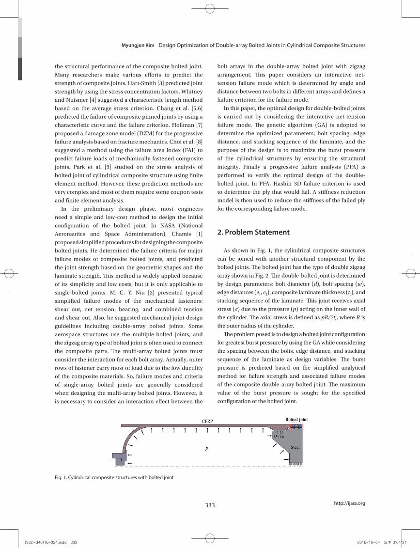
As shown in Fig. 1, the cylindrical composite structures
can be joined with another structural component by the
bolted joints. The bolted joint has the type of double zigzag
array shown in Fig. 2. The double-bolted joint is determined
by design parameters: bolt diameter (d), bolt spacing (w),
edge distances (e1, e2), composite laminate thickness (tc), and
stacking sequence of the laminate. This joint receives axial
stress (σ) due to the pressure (p) acting on the inner wall of
the cylinder. The axial stress is defined as pR/2tc, where R is
the outer radius of the cylinder.
The problem posed is to design a bolted joint configuration
for greatest burst pressure by using the GA while considering
the spacing between the bolts, edge distance, and stacking
sequence of the laminate as design variables. The burst
pressure is predicted based on the simplified analytical
method for failure strength and associated failure modes
of the composite double-array bolted joint. The maximum
value of the burst pressure is sought for the specified
configuration of the bolted joint.
14
List of Figures
Fig. 1. Cylindrical composite structures with bolted joint
Fig. 2. Design parameters of double-bolted joint with zigzag array
Fig. 3. Typical failure modes of composite bolted joint
Fig. 1. Cylindrical composite structures with bolted joint
(332~340)16-024.indd 333 2016-10-04 오후 3:04:31
DOI: http://dx.doi.org/10.5139/IJASS.2016.17.3.332 334
Int’l J. of Aeronautical & Space Sci. 17(3), 332–340 (2016)
3. Failure modes and analysis for composite double-bolted joints
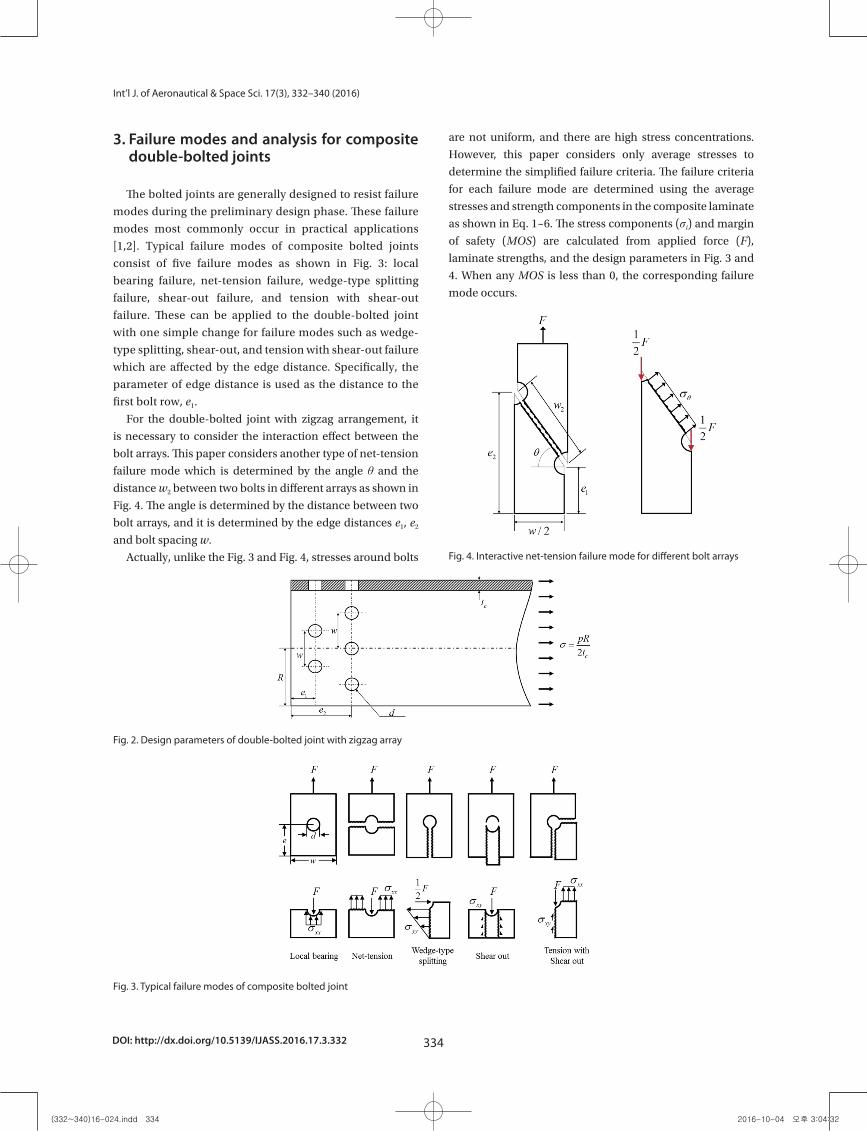
The bolted joints are generally designed to resist failure
modes during the preliminary design phase. These failure
modes most commonly occur in practical applications
[1,2]. Typical failure modes of composite bolted joints
consist of five failure modes as shown in Fig. 3: local
bearing failure, net-tension failure, wedge-type splitting
failure, shear-out failure, and tension with shear-out
failure. These can be applied to the double-bolted joint
with one simple change for failure modes such as wedge-
type splitting, shear-out, and tension with shear-out failure
which are affected by the edge distance. Specifically, the
parameter of edge distance is used as the distance to the
first bolt row, e1.
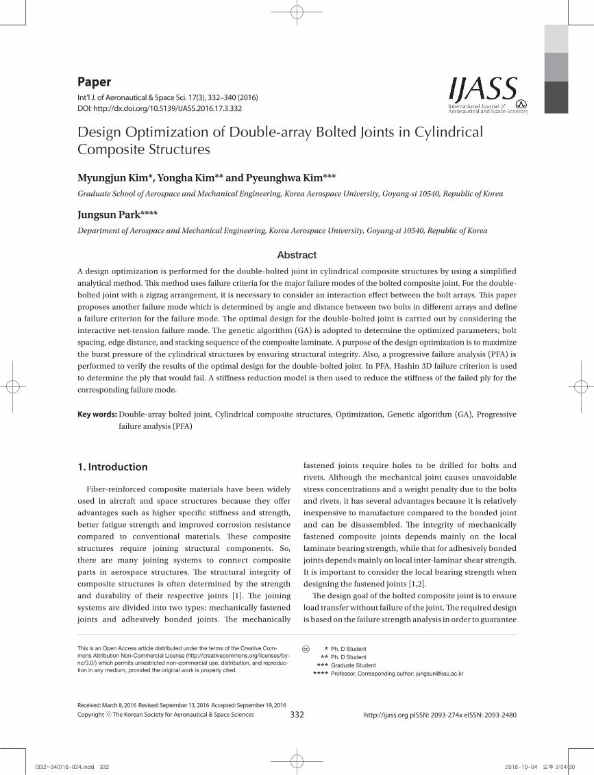
For the double-bolted joint with zigzag arrangement, it
is necessary to consider the interaction effect between the
bolt arrays. This paper considers another type of net-tension
failure mode which is determined by the angle θ and the
distance w2 between two bolts in different arrays as shown in
Fig. 4. The angle is determined by the distance between two
bolt arrays, and it is determined by the edge distances e1, e2
and bolt spacing w.
Actually, unlike the Fig. 3 and Fig. 4, stresses around bolts
are not uniform, and there are high stress concentrations.
However, this paper considers only average stresses to
determine the simplified failure criteria. The failure criteria
for each failure mode are determined using the average
stresses and strength components in the composite laminate
as shown in Eq. 1~6. The stress components (σi) and margin
of safety (MOS) are calculated from applied force (F),
laminate strengths, and the design parameters in Fig. 3 and
4. When any MOS is less than 0, the corresponding failure
mode occurs.
14
List of Figures
Fig. 1. Cylindrical composite structures with bolted joint
Fig. 2. Design parameters of double-bolted joint with zigzag array
Fig. 3. Typical failure modes of composite bolted joint
Fig. 2. Design parameters of double-bolted joint with zigzag array
14
List of Figures
Fig. 1. Cylindrical composite structures with bolted joint
Fig. 2. Design parameters of double-bolted joint with zigzag array
Fig. 3. Typical failure modes of composite bolted joint Fig. 3. Typical failure modes of composite bolted joint
15
Fig. 4. Interactive net-tension failure mode for different bolt arrays
Fig. 5. Flow chart of design optimization program for composite double-bolted joint
Fig. 4. Interactive net-tension failure mode for different bolt arrays
(332~340)16-024.indd 334 2016-10-04 오후 3:04:32
335
Myungjun Kim Design Optimization of Double-array Bolted Joints in Cylindrical Composite Structures
http://ijass.org
Local bearing failure mode:
5
distance. Specifically, the parameter of edge distance is used as the distance to the first bolt row, e1.
Fig. 3. Typical failure modes of composite bolted joint
For the double-bolted joint with zigzag arrangement, it is necessary to consider the interaction
effect between the bolt arrays. This paper considers another type of net-tension failure mode which is
determined by the angle and the distance w2 between two bolts in different arrays as shown in Fig.
4. The angle is determined by the distance between two bolt arrays, and it is determined by the edge
distances e1, e2 and bolt spacing w.
Fig. 4. Interactive net-tension failure mode for different bolt arrays
Actually, unlike the Fig. 3 and Fig. 4, stresses around bolts are not uniform, and there are high
stress concentrations. However, this paper considers only average stresses to determine the simplified
failure criteria. The failure criteria for each failure mode are determined using the average stresses and
strength components in the composite laminate as shown in Eq. 1~6. The stress components ( ) and
margin of safety (MOS) are calculated from applied force (F), laminate strengths, and the design
parameters in Fig. 3 and 4. When any MOS is less than 0, the corresponding failure mode occurs.
Local bearing failure mode: 1, xxCbr xx
xx c
S FMOSSF dt
(1)
Net-tension failure mode: 1, ( )
xxTnt xx
xx c
S FMOSSF w d t
(2)
Wedge-type splitting failure mode: 1
21, (2 )
yyTwt yy
yy c
S FMOSSF e d t
(3)
Shear-out failure mode: 1
1, 2
xySso xy
xy c
S FMOSSF e t
(4)
(1)
Net-tension failure mode:
5
distance. Specifically, the parameter of edge distance is used as the distance to the first bolt row, e1.
Fig. 3. Typical failure modes of composite bolted joint
For the double-bolted joint with zigzag arrangement, it is necessary to consider the interaction
effect between the bolt arrays. This paper considers another type of net-tension failure mode which is
determined by the angle and the distance w2 between two bolts in different arrays as shown in Fig.
4. The angle is determined by the distance between two bolt arrays, and it is determined by the edge
distances e1, e2 and bolt spacing w.
Fig. 4. Interactive net-tension failure mode for different bolt arrays
Actually, unlike the Fig. 3 and Fig. 4, stresses around bolts are not uniform, and there are high
stress concentrations. However, this paper considers only average stresses to determine the simplified
failure criteria. The failure criteria for each failure mode are determined using the average stresses and
strength components in the composite laminate as shown in Eq. 1~6. The stress components ( ) and
margin of safety (MOS) are calculated from applied force (F), laminate strengths, and the design
parameters in Fig. 3 and 4. When any MOS is less than 0, the corresponding failure mode occurs.
Local bearing failure mode: 1, xxCbr xx
xx c
S FMOSSF dt
(1)
Net-tension failure mode: 1, ( )
xxTnt xx
xx c
S FMOSSF w d t
(2)
Wedge-type splitting failure mode: 1
21, (2 )
yyTwt yy
yy c
S FMOSSF e d t
(3)
Shear-out failure mode: 1
1, 2
xySso xy
xy c
S FMOSSF e t
(4)
(2)
Wedge-type splitting failure mode:
5
distance. Specifically, the parameter of edge distance is used as the distance to the first bolt row, e1.
Fig. 3. Typical failure modes of composite bolted joint
For the double-bolted joint with zigzag arrangement, it is necessary to consider the interaction
effect between the bolt arrays. This paper considers another type of net-tension failure mode which is
determined by the angle and the distance w2 between two bolts in different arrays as shown in Fig.
4. The angle is determined by the distance between two bolt arrays, and it is determined by the edge
distances e1, e2 and bolt spacing w.
Fig. 4. Interactive net-tension failure mode for different bolt arrays
Actually, unlike the Fig. 3 and Fig. 4, stresses around bolts are not uniform, and there are high
stress concentrations. However, this paper considers only average stresses to determine the simplified
failure criteria. The failure criteria for each failure mode are determined using the average stresses and
strength components in the composite laminate as shown in Eq. 1~6. The stress components ( ) and
margin of safety (MOS) are calculated from applied force (F), laminate strengths, and the design
parameters in Fig. 3 and 4. When any MOS is less than 0, the corresponding failure mode occurs.
Local bearing failure mode: 1, xxCbr xx
xx c
S FMOSSF dt
(1)
Net-tension failure mode: 1, ( )
xxTnt xx
xx c
S FMOSSF w d t
(2)
Wedge-type splitting failure mode: 1
21, (2 )
yyTwt yy
yy c
S FMOSSF e d t
(3)
Shear-out failure mode: 1
1, 2
xySso xy
xy c
S FMOSSF e t
(4)
(3)
Shear-out failure mode:
5
distance. Specifically, the parameter of edge distance is used as the distance to the first bolt row, e1.
Fig. 3. Typical failure modes of composite bolted joint
For the double-bolted joint with zigzag arrangement, it is necessary to consider the interaction
effect between the bolt arrays. This paper considers another type of net-tension failure mode which is
determined by the angle and the distance w2 between two bolts in different arrays as shown in Fig.
4. The angle is determined by the distance between two bolt arrays, and it is determined by the edge
distances e1, e2 and bolt spacing w.
Fig. 4. Interactive net-tension failure mode for different bolt arrays
Actually, unlike the Fig. 3 and Fig. 4, stresses around bolts are not uniform, and there are high
stress concentrations. However, this paper considers only average stresses to determine the simplified
failure criteria. The failure criteria for each failure mode are determined using the average stresses and
strength components in the composite laminate as shown in Eq. 1~6. The stress components ( ) and
margin of safety (MOS) are calculated from applied force (F), laminate strengths, and the design
parameters in Fig. 3 and 4. When any MOS is less than 0, the corresponding failure mode occurs.
Local bearing failure mode: 1, xxCbr xx
xx c
S FMOSSF dt
(1)
Net-tension failure mode: 1, ( )
xxTnt xx
xx c
S FMOSSF w d t
(2)
Wedge-type splitting failure mode: 1
21, (2 )
yyTwt yy
yy c
S FMOSSF e d t
(3)
Shear-out failure mode: 1
1, 2
xySso xy
xy c
S FMOSSF e t
(4) (4)
Tension with shear-out failure mode:
6
Tension with shear-out failure mode: 1[( ) 2 ]1,
2c xxT xyStso
tso tso
t w d S e SFMOS F
F SF
(5)
Interactive net-tension failure mode: 2
cos1, ( )
xxTint
c
S FMOSSF w d t
(6)
Herein, MOSi (i=br, nt, wt, so, tso, int) is the margin of safety for the corresponding failure mode, and
br, nt, wt, so, tso, int mean the local bearing, net-tension, wedge-type splitting, shear-out, tension with
shear-out, and interactive net-tension failure mode, respectively. xxTS , xxCS , yyTS , yyCS , xySS are the
longitudinal tensile/compressive, transverse tensile/compressive, and in-plane shear strength of the
laminate. xxTS is the interactive tensile strength of the laminate, which is determined by using the
longitudinal tensile strength of the off-axis laminate. The applied force F is obtained by the
product of the axial stress and its area ( cF wt ), and the applied safety factor SF is 1.6. These failure
criteria are applied to design constraints in the optimization problem of composite double-bolted
joints. Also, the strengths of fiber-reinforced composite materials are generally determined for the
unidirectional laminate. So, the strength of multi-layered laminate should be predicted by using a
specific composite failure theory. In this paper, the five strength components ( xxTS , xxCS , yyTS , yyCS ,
xySS ) of the multi-layered laminate which has any stacking sequence are predicted based on the first-
ply failure and maximum stress failure criteria.
4. Optimal design of composite double-bolted joints
In this paper, the genetic algorithm (GA) is used as the optimization method to design the
composite double-bolted joint. An optimization problem is formulated based on the failure criteria and
some design parameters of the bolted joint. The optimal design code is generated using MATLAB.
4.1 Genetic algorithm (GA)
The genetic algorithm (GA) is a direct, parallel, stochastic search method widely used for global
searches and an optimization tool based on principles of natural selection and genetics described by
(5)
Interactive net-tension failure mode:
6
Tension with shear-out failure mode: 1[( ) 2 ]1,
2c xxT xyStso
tso tso
t w d S e SFMOS F
F SF
(5)
Interactive net-tension failure mode: 2
cos1, ( )
xxTint
c
S FMOSSF w d t
(6)
Herein, MOSi (i=br, nt, wt, so, tso, int) is the margin of safety for the corresponding failure mode, and
br, nt, wt, so, tso, int mean the local bearing, net-tension, wedge-type splitting, shear-out, tension with
shear-out, and interactive net-tension failure mode, respectively. xxTS , xxCS , yyTS , yyCS , xySS are the
longitudinal tensile/compressive, transverse tensile/compressive, and in-plane shear strength of the
laminate. xxTS is the interactive tensile strength of the laminate, which is determined by using the
longitudinal tensile strength of the off-axis laminate. The applied force F is obtained by the
product of the axial stress and its area ( cF wt ), and the applied safety factor SF is 1.6. These failure
criteria are applied to design constraints in the optimization problem of composite double-bolted
joints. Also, the strengths of fiber-reinforced composite materials are generally determined for the
unidirectional laminate. So, the strength of multi-layered laminate should be predicted by using a
specific composite failure theory. In this paper, the five strength components ( xxTS , xxCS , yyTS , yyCS ,
xySS ) of the multi-layered laminate which has any stacking sequence are predicted based on the first-
ply failure and maximum stress failure criteria.
4. Optimal design of composite double-bolted joints
In this paper, the genetic algorithm (GA) is used as the optimization method to design the
composite double-bolted joint. An optimization problem is formulated based on the failure criteria and
some design parameters of the bolted joint. The optimal design code is generated using MATLAB.
4.1 Genetic algorithm (GA)
The genetic algorithm (GA) is a direct, parallel, stochastic search method widely used for global
searches and an optimization tool based on principles of natural selection and genetics described by
(6)
Herein, MOSi (i=br, nt, wt, so, tso, int) is the margin of
safety for the corresponding failure mode, and br, nt, wt,
so, tso, int mean the local bearing, net-tension, wedge-type
splitting, shear-out, tension with shear-out, and interactive
net-tension failure mode, respectively. SxxT, SxxC, SyyT, SyyC, SxyC
are the longitudinal tensile/compressive, transverse tensile/
compressive, and in-plane shear strength of the laminate.
SθxxT is the interactive tensile strength of the laminate, which
is determined by using the longitudinal tensile strength
of the θ off-axis laminate. The applied force F is obtained
by the product of the axial stress and its area (F=σwtc), and
the applied safety factor SF is 1.6. These failure criteria are
applied to design constraints in the optimization problem of
composite double-bolted joints. Also, the strengths of fiber-
reinforced composite materials are generally determined for
the unidirectional laminate. So, the strength of multi-layered
laminate should be predicted by using a specific composite
failure theory. In this paper, the five strength components
(SxxT, SxxC, SyyT, SyyC, SxyS) of the multi-layered laminate which
has any stacking sequence are predicted based on the first-
ply failure and the maximum stress failure criteria.
4. Optimal design of composite double-bolted joints
In this paper, the genetic algorithm (GA) is used as the
optimization method to design the composite double-bolted
joint. An optimization problem is formulated based on the
failure criteria and some design parameters of the bolted
joint. The optimal design code is generated using MATLAB.
4.1 Genetic algorithm (GA)
The genetic algorithm (GA) is a direct, parallel, stochastic
search method widely used for global searches and an
optimization tool based on principles of natural selection
and genetics described by Darwin. This optimization
algorithm uses the three processes of selection, cross-over,
and mutation for a population consisting of a combination
of binary numbers. The GA starts with the generation of the
initial random population about design variables, and each
number of the population is then evaluated based on the
fitness value by the process of selection. Each member of
the next generation is created by the cross-over process that
represents the exchange of genes of the parents to produce
offspring. The processes of mutation and permutation are
also applied to some members in the new generation by
perturbing the genes in order to expand the search space.
The GA is suitable for finding the global optimum because
the best design is always transferred from the previous
generation to the next generation [9,10]. For this reason, the
GA is selected as an optimization algorithm in this paper.
4.2 Formulation of the optimization problem
The purpose of formulation is to create a mathematical
model of the optimal design problem, which can then be
solved using an optimization algorithm. In this paper, the
design objective is to maximize the burst pressure (pf) by
ensuring safety margins for the critical failure modes of the
double-bolted joint in cylindrical composite structures. We
consider three design variables, including bolt spacing (w),
edge distance to the first low (e1), and stacking sequence of the
laminate. The edge distance to the second bolt row (e2) and the
thickness of the laminate (tc) are assumed as constant values
in order to simplify the optimization problem. Also, the bolt
diameter (d) is not considered as a design variable because the
bolt type and specifications are generally determined before
the structural design stage for bolted joints. The stacking
sequence of the laminate is determined by combining three
plies which have angles of 0°, ±45°, 90°. The designed laminate
is laid on the basal laminate which is determined by designing
the other parts in cylindrical composite structures.
The safety margins to be calculated by the failure criteria
are specified as design constraints to ensure the structural
integrity of the composite bolted joint. The bearing
failure mode shows progressive failure characteristics (no
(332~340)16-024.indd 335 2016-10-04 오후 3:04:33
DOI: http://dx.doi.org/10.5139/IJASS.2016.17.3.332 336
Int’l J. of Aeronautical & Space Sci. 17(3), 332–340 (2016)
catastrophic failure of the laminate) among the failure
modes, so it is more desirable than other failure modes. For
this reason, the margin of safety for local bearing failure
is determined to be a smaller value than the minimum
safety margin of the other failure modes. And, the MOSbr is
set to zero when the pressure reaches the burst pressure.
Also, the design variables are constrained within geometry
configuration limits. A formulated model for the optimization
problem is shown in Eq. 7.
8
The MOSbr is set to zero when the pressure reaches the burst pressure. Also, the design variables are
constrained within geometry configuration limits. A formulated model for the optimization problem is
shown in Eq. 7.
@
@ @
1 1 1
Max ( ) S.T. ( ) 0
( ) min( , , , , )
f
f f
f
br p
br p nt wt so tso int p
l u
l u
pMOS
MOS MOS MOS MOS MOS MOS
e e ew w w
(7)
Herein, the superscript, l and u mean the lower and upper bounds of side constraints, respectively.
These boundary conditions are determined by the geometric configuration of the cylindrical
composite structures. The ranges of design variables used in this paper are 113 mm 38 mme , and
17 mm 260 mmw . The MOSi s are calculated from Eq. 1~6 at the burst pressure. Since the MOSbr is
0 at the burst pressure, the first failure of the double-bolted joint will occur within the local bearing
failure mode. Also, the other failure modes have a greater safety margin than the bearing failure mode.
Based on the design criteria, the constraints functions are defined by Eq. 8 ~ 13.
1 @( ) 0fbr pG MOS (8)
2 @( ) 0fbr nt pG MOS MOS (9)
3 @( ) 0fbr wt pG MOS MOS (10)
4 @( ) 0fbr so pG MOS MOS (11)
5 @( ) 0fbr tso pG MOS MOS (12)
6 @( ) 0fbr int pG MOS MOS (13)
From the formulated model, a design optimization program is coded based on GA and the
simplified failure criteria of the composite double-bolted joint. The flow chart of the program is
(7)
Herein, the superscript, l and u mean the lower and upper
bounds of side constraints, respectively. These boundary
conditions are determined by the geometric configuration
of the cylindrical composite structures. The ranges of design
variables used in this paper are 13mm≤e1≤38mm, and
17mm≤w≤260mm. The MOSi s are calculated from Eq. 1~6 at
the burst pressure. Since the MOSbr is 0 at the burst pressure,
the first failure of the double-bolted joint will occur within
the local bearing failure mode. Also, the other failure modes
have a greater safety margin than the bearing failure mode.
Based on the design criteria, the constraints functions are
defined by Eq. 8 ~ 13.
8
The MOSbr is set to zero when the pressure reaches the burst pressure. Also, the design variables are
constrained within geometry configuration limits. A formulated model for the optimization problem is
shown in Eq. 7.
@
@ @
1 1 1
Max ( ) S.T. ( ) 0
( ) min( , , , , )
f
f f
f
br p
br p nt wt so tso int p
l u
l u
pMOS
MOS MOS MOS MOS MOS MOS
e e ew w w
(7)
Herein, the superscript, l and u mean the lower and upper bounds of side constraints, respectively.
These boundary conditions are determined by the geometric configuration of the cylindrical
composite structures. The ranges of design variables used in this paper are 113 mm 38 mme , and
17 mm 260 mmw . The MOSi s are calculated from Eq. 1~6 at the burst pressure. Since the MOSbr is
0 at the burst pressure, the first failure of the double-bolted joint will occur within the local bearing
failure mode. Also, the other failure modes have a greater safety margin than the bearing failure mode.
Based on the design criteria, the constraints functions are defined by Eq. 8 ~ 13.
1 @( ) 0fbr pG MOS (8)
2 @( ) 0fbr nt pG MOS MOS (9)
3 @( ) 0fbr wt pG MOS MOS (10)
4 @( ) 0fbr so pG MOS MOS (11)
5 @( ) 0fbr tso pG MOS MOS (12)
6 @( ) 0fbr int pG MOS MOS (13)
From the formulated model, a design optimization program is coded based on GA and the
simplified failure criteria of the composite double-bolted joint. The flow chart of the program is
(8)
8
The MOSbr is set to zero when the pressure reaches the burst pressure. Also, the design variables are
constrained within geometry configuration limits. A formulated model for the optimization problem is
shown in Eq. 7.
@
@ @
1 1 1
Max ( ) S.T. ( ) 0
( ) min( , , , , )
f
f f
f
br p
br p nt wt so tso int p
l u
l u
pMOS
MOS MOS MOS MOS MOS MOS
e e ew w w
(7)
Herein, the superscript, l and u mean the lower and upper bounds of side constraints, respectively.
These boundary conditions are determined by the geometric configuration of the cylindrical
composite structures. The ranges of design variables used in this paper are 113 mm 38 mme , and
17 mm 260 mmw . The MOSi s are calculated from Eq. 1~6 at the burst pressure. Since the MOSbr is
0 at the burst pressure, the first failure of the double-bolted joint will occur within the local bearing
failure mode. Also, the other failure modes have a greater safety margin than the bearing failure mode.
Based on the design criteria, the constraints functions are defined by Eq. 8 ~ 13.
1 @( ) 0fbr pG MOS (8)
2 @( ) 0fbr nt pG MOS MOS (9)
3 @( ) 0fbr wt pG MOS MOS (10)
4 @( ) 0fbr so pG MOS MOS (11)
5 @( ) 0fbr tso pG MOS MOS (12)
6 @( ) 0fbr int pG MOS MOS (13)
From the formulated model, a design optimization program is coded based on GA and the
simplified failure criteria of the composite double-bolted joint. The flow chart of the program is
(9)
8
The MOSbr is set to zero when the pressure reaches the burst pressure. Also, the design variables are
constrained within geometry configuration limits. A formulated model for the optimization problem is
shown in Eq. 7.
@
@ @
1 1 1
Max ( ) S.T. ( ) 0
( ) min( , , , , )
f
f f
f
br p
br p nt wt so tso int p
l u
l u
pMOS
MOS MOS MOS MOS MOS MOS
e e ew w w
(7)
Herein, the superscript, l and u mean the lower and upper bounds of side constraints, respectively.
These boundary conditions are determined by the geometric configuration of the cylindrical
composite structures. The ranges of design variables used in this paper are 113 mm 38 mme , and
17 mm 260 mmw . The MOSi s are calculated from Eq. 1~6 at the burst pressure. Since the MOSbr is
0 at the burst pressure, the first failure of the double-bolted joint will occur within the local bearing
failure mode. Also, the other failure modes have a greater safety margin than the bearing failure mode.
Based on the design criteria, the constraints functions are defined by Eq. 8 ~ 13.
1 @( ) 0fbr pG MOS (8)
2 @( ) 0fbr nt pG MOS MOS (9)
3 @( ) 0fbr wt pG MOS MOS (10)
4 @( ) 0fbr so pG MOS MOS (11)
5 @( ) 0fbr tso pG MOS MOS (12)
6 @( ) 0fbr int pG MOS MOS (13)
From the formulated model, a design optimization program is coded based on GA and the
simplified failure criteria of the composite double-bolted joint. The flow chart of the program is
(10)
8
The MOSbr is set to zero when the pressure reaches the burst pressure. Also, the design variables are
constrained within geometry configuration limits. A formulated model for the optimization problem is
shown in Eq. 7.
@
@ @
1 1 1
Max ( ) S.T. ( ) 0
( ) min( , , , , )
f
f f
f
br p
br p nt wt so tso int p
l u
l u
pMOS
MOS MOS MOS MOS MOS MOS
e e ew w w
(7)
Herein, the superscript, l and u mean the lower and upper bounds of side constraints, respectively.
These boundary conditions are determined by the geometric configuration of the cylindrical
composite structures. The ranges of design variables used in this paper are 113 mm 38 mme , and
17 mm 260 mmw . The MOSi s are calculated from Eq. 1~6 at the burst pressure. Since the MOSbr is
0 at the burst pressure, the first failure of the double-bolted joint will occur within the local bearing
failure mode. Also, the other failure modes have a greater safety margin than the bearing failure mode.
Based on the design criteria, the constraints functions are defined by Eq. 8 ~ 13.
1 @( ) 0fbr pG MOS (8)
2 @( ) 0fbr nt pG MOS MOS (9)
3 @( ) 0fbr wt pG MOS MOS (10)
4 @( ) 0fbr so pG MOS MOS (11)
5 @( ) 0fbr tso pG MOS MOS (12)
6 @( ) 0fbr int pG MOS MOS (13)
From the formulated model, a design optimization program is coded based on GA and the
simplified failure criteria of the composite double-bolted joint. The flow chart of the program is
(11)
8
The MOSbr is set to zero when the pressure reaches the burst pressure. Also, the design variables are
constrained within geometry configuration limits. A formulated model for the optimization problem is
shown in Eq. 7.
@
@ @
1 1 1
Max ( ) S.T. ( ) 0
( ) min( , , , , )
f
f f
f
br p
br p nt wt so tso int p
l u
l u
pMOS
MOS MOS MOS MOS MOS MOS
e e ew w w
(7)
Herein, the superscript, l and u mean the lower and upper bounds of side constraints, respectively.
These boundary conditions are determined by the geometric configuration of the cylindrical
composite structures. The ranges of design variables used in this paper are 113 mm 38 mme , and
17 mm 260 mmw . The MOSi s are calculated from Eq. 1~6 at the burst pressure. Since the MOSbr is
0 at the burst pressure, the first failure of the double-bolted joint will occur within the local bearing
failure mode. Also, the other failure modes have a greater safety margin than the bearing failure mode.
Based on the design criteria, the constraints functions are defined by Eq. 8 ~ 13.
1 @( ) 0fbr pG MOS (8)
2 @( ) 0fbr nt pG MOS MOS (9)
3 @( ) 0fbr wt pG MOS MOS (10)
4 @( ) 0fbr so pG MOS MOS (11)
5 @( ) 0fbr tso pG MOS MOS (12)
6 @( ) 0fbr int pG MOS MOS (13)
From the formulated model, a design optimization program is coded based on GA and the
simplified failure criteria of the composite double-bolted joint. The flow chart of the program is
(12)
8
The MOSbr is set to zero when the pressure reaches the burst pressure. Also, the design variables are
constrained within geometry configuration limits. A formulated model for the optimization problem is
shown in Eq. 7.
@
@ @
1 1 1
Max ( ) S.T. ( ) 0
( ) min( , , , , )
f
f f
f
br p
br p nt wt so tso int p
l u
l u
pMOS
MOS MOS MOS MOS MOS MOS
e e ew w w
(7)
Herein, the superscript, l and u mean the lower and upper bounds of side constraints, respectively.
These boundary conditions are determined by the geometric configuration of the cylindrical
composite structures. The ranges of design variables used in this paper are 113 mm 38 mme , and
17 mm 260 mmw . The MOSi s are calculated from Eq. 1~6 at the burst pressure. Since the MOSbr is
0 at the burst pressure, the first failure of the double-bolted joint will occur within the local bearing
failure mode. Also, the other failure modes have a greater safety margin than the bearing failure mode.
Based on the design criteria, the constraints functions are defined by Eq. 8 ~ 13.
1 @( ) 0fbr pG MOS (8)
2 @( ) 0fbr nt pG MOS MOS (9)
3 @( ) 0fbr wt pG MOS MOS (10)
4 @( ) 0fbr so pG MOS MOS (11)
5 @( ) 0fbr tso pG MOS MOS (12)
6 @( ) 0fbr int pG MOS MOS (13)
From the formulated model, a design optimization program is coded based on GA and the
simplified failure criteria of the composite double-bolted joint. The flow chart of the program is
(13)
Table 1. Mechanical properties and strengths of T800 carbon/epoxy composite material
18
List of tables
Table 1. Mechanical properties and strengths of T800 carbon/epoxy composite material
Properties Values [MPa] Strengths Values [MPa]
E11 170,500 XT 2,894
E22=E33 8,830 XC 1,962
G12=G13 4,900 YT 43
G23 2,450 YC 164
v12=v13 0.3 S 93
v23 0.4 ST 77
Table 2. Results of the design optimization
Objective function pf [MPa] 28.7613
Design variables
e1 [mm] 24.5159
w [mm] 25.9181
stackingsequence [90°/±10°/(±45°)5/06/904]
Constraints
G1 -0.0000
G2 -0.0203
G3 -0.0104
G4 -0.8766
G5 -0.4484
G6 -0.0065
Table 3. Results of margin of safety for optimum design
Margin of safefy Values
MOSbr 0
MOSnt 0.0203
MOSwt 0.0104
MOSso 0.8766
MOStso 0.4484
MOSint 0.0065
15
Fig. 4. Interactive net-tension failure mode for different bolt arrays
Fig. 5. Flow chart of design optimization program for composite double-bolted joint Fig. 5. Flow chart of design optimization program for composite double-bolted joint
(332~340)16-024.indd 336 2016-10-04 오후 3:04:34
337
Myungjun Kim Design Optimization of Double-array Bolted Joints in Cylindrical Composite Structures
http://ijass.org
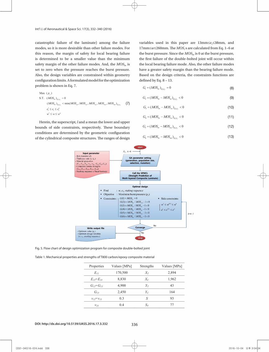
From the formulated model, a design optimization program
is coded based on GA and the simplified failure criteria of the
composite double-bolted joint. The flow chart of the program
is shown in Fig. 5. The SPMCL is an in-house code for the
strength prediction of multi-layered composite laminate
based on the composite failure criteria. This is implemented
when a stacking sequence of laminate is determined for each
increment in the process of optimization.
4.3 Optimal design results
The cylindrical composite structure considered in this
paper has an outer radius (R) of 82.5 mm. In the composite
double-bolted joint, the edge distance to the second bolt
row (e2), bolt diameter (d), and thickness of the laminate
(tc) are fixed as 42 mm, 8 mm, and 7 mm, respectively. The
composite material used for this study is T800 carbon/epoxy,
and the ply thickness is 0.25 mm. The basal laminate has a
stacking sequence of [90°/±10°] and a thickness of 2.0 mm.
The mechanical properties and strengths of the T800 carbon/
epoxy composite material are listed in Table 1.
The GA needs to determine the optimization parameters
such as generation and population sizes, and the factors
of selection and mutation. In this paper, the generation
and population sizes are set to 500 and 20, and the factors
of selection and mutation are 0.5 and 0.2, respectively. The
results of design optimization based on GA are shown in
Table 2. Table 3 shows the safety margins for each failure
mode in regard to the optimal design. In the optimization
process as shown in Fig. 5, the strengths of the designed
total laminate are predicted by the SPMCL function. Table
4 represents the strengths of the composite laminate which
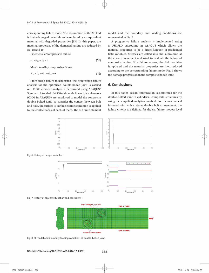
has an optimum stacking sequence. The history of the design
variables, objective function, and constraints are shown in
Figs. 6 and 7.
5. Numerical verification
To verify the results of optimization, a failure mode at
the burst pressure of the optimized double-bolted joint
is evaluated by the progressive failure analysis (PFA). The
Hashin 3D failure criterion is used to determine the ply
that would fail [12]. Four failure modes are assumed by the
Hashin’s failure theory, which are given by Eq. 14~17.
Fiber tension:
10
Fig. 5. Flow chart of design optimization program for composite double-bolted joint
Table 4. Strengths of laminate for optimum design
Fig. 6. History of design variables
Fig. 7. History of objective function and constraints
5. Numerical verification
To verify the results of optimization, a failure mode at the burst pressure of the optimized double-
bolted joint is evaluated by the progressive failure analysis (PFA). The Hashin 3D failure criterion is used
to determine the ply that would fail [12]. Four failure modes are assumed by the Hashin’s failure theory,
which are given by Eq. 14~17.
Fiber tension: 2 2 2
12 13112
( ) 1TX S
(14)
Fiber compression: 11 CX (15)
Matrix tension: 2 2 2 2
22 33 23 22 33 12 132 2 2
( ) ( ) ( ) 1T TY S S
(16)
Matrix compression: 2 2 2 2 2
22 33 22 33 23 22 33 12 132 2 2
( ) ( ) ( ) ( )1 12 4
C
C T T T
YY S S S S
(17)
Also, the material property degradation model (MPDM) is used to reduce the stiffness of the failed
laminate in the corresponding failure mode. The assumption of the MPDM is that a damaged material can
be replaced by an equivalent material with degraded properties [13]. In this paper, the material properties
of the damaged lamina are reduced by Eq. 18 and 19.
Fiber tensile/compressive failure: 11 12 13 0E v v (18)
(14)
Fiber compression:
10
Fig. 5. Flow chart of design optimization program for composite double-bolted joint
Table 4. Strengths of laminate for optimum design
Fig. 6. History of design variables
Fig. 7. History of objective function and constraints
5. Numerical verification
To verify the results of optimization, a failure mode at the burst pressure of the optimized double-
bolted joint is evaluated by the progressive failure analysis (PFA). The Hashin 3D failure criterion is used
to determine the ply that would fail [12]. Four failure modes are assumed by the Hashin’s failure theory,
which are given by Eq. 14~17.
Fiber tension: 2 2 2
12 13112
( ) 1TX S
(14)
Fiber compression: 11 CX (15)
Matrix tension: 2 2 2 2
22 33 23 22 33 12 132 2 2
( ) ( ) ( ) 1T TY S S
(16)
Matrix compression: 2 2 2 2 2
22 33 22 33 23 22 33 12 132 2 2
( ) ( ) ( ) ( )1 12 4
C
C T T T
YY S S S S
(17)
Also, the material property degradation model (MPDM) is used to reduce the stiffness of the failed
laminate in the corresponding failure mode. The assumption of the MPDM is that a damaged material can
be replaced by an equivalent material with degraded properties [13]. In this paper, the material properties
of the damaged lamina are reduced by Eq. 18 and 19.
Fiber tensile/compressive failure: 11 12 13 0E v v (18)
(15)
Matrix tension:
10
Fig. 5. Flow chart of design optimization program for composite double-bolted joint
Table 4. Strengths of laminate for optimum design
Fig. 6. History of design variables
Fig. 7. History of objective function and constraints
5. Numerical verification
To verify the results of optimization, a failure mode at the burst pressure of the optimized double-
bolted joint is evaluated by the progressive failure analysis (PFA). The Hashin 3D failure criterion is used
to determine the ply that would fail [12]. Four failure modes are assumed by the Hashin’s failure theory,
which are given by Eq. 14~17.
Fiber tension: 2 2 2
12 13112
( ) 1TX S
(14)
Fiber compression: 11 CX (15)
Matrix tension: 2 2 2 2
22 33 23 22 33 12 132 2 2
( ) ( ) ( ) 1T TY S S
(16)
Matrix compression: 2 2 2 2 2
22 33 22 33 23 22 33 12 132 2 2
( ) ( ) ( ) ( )1 12 4
C
C T T T
YY S S S S
(17)
Also, the material property degradation model (MPDM) is used to reduce the stiffness of the failed
laminate in the corresponding failure mode. The assumption of the MPDM is that a damaged material can
be replaced by an equivalent material with degraded properties [13]. In this paper, the material properties
of the damaged lamina are reduced by Eq. 18 and 19.
Fiber tensile/compressive failure: 11 12 13 0E v v (18)
(16)
Matrix compression:
10
Fig. 5. Flow chart of design optimization program for composite double-bolted joint
Table 4. Strengths of laminate for optimum design
Fig. 6. History of design variables
Fig. 7. History of objective function and constraints
5. Numerical verification
To verify the results of optimization, a failure mode at the burst pressure of the optimized double-
bolted joint is evaluated by the progressive failure analysis (PFA). The Hashin 3D failure criterion is used
to determine the ply that would fail [12]. Four failure modes are assumed by the Hashin’s failure theory,
which are given by Eq. 14~17.
Fiber tension: 2 2 2
12 13112
( ) 1TX S
(14)
Fiber compression: 11 CX (15)
Matrix tension: 2 2 2 2
22 33 23 22 33 12 132 2 2
( ) ( ) ( ) 1T TY S S
(16)
Matrix compression: 2 2 2 2 2
22 33 22 33 23 22 33 12 132 2 2
( ) ( ) ( ) ( )1 12 4
C
C T T T
YY S S S S
(17)
Also, the material property degradation model (MPDM) is used to reduce the stiffness of the failed
laminate in the corresponding failure mode. The assumption of the MPDM is that a damaged material can
be replaced by an equivalent material with degraded properties [13]. In this paper, the material properties
of the damaged lamina are reduced by Eq. 18 and 19.
Fiber tensile/compressive failure: 11 12 13 0E v v (18)
(17)
Also, the material property degradation model (MPDM)
is used to reduce the stiffness of the failed laminate in the
Table 2. Results of the design optimization
18
List of tables
Table 1. Mechanical properties and strengths of T800 carbon/epoxy composite material
Properties Values [MPa] Strengths Values [MPa]
E11 170,500 XT 2,894
E22=E33 8,830 XC 1,962
G12=G13 4,900 YT 43
G23 2,450 YC 164
v12=v13 0.3 S 93
v23 0.4 ST 77
Table 2. Results of the design optimization
Objective function pf [MPa] 28.7613
Design variables
e1 [mm] 24.5159
w [mm] 25.9181
stackingsequence [90°/±10°/(±45°)5/06/904]
Constraints
G1 -0.0000
G2 -0.0203
G3 -0.0104
G4 -0.8766
G5 -0.4484
G6 -0.0065
Table 3. Results of margin of safety for optimum design
Margin of safefy Values
MOSbr 0
MOSnt 0.0203
MOSwt 0.0104
MOSso 0.8766
MOStso 0.4484
MOSint 0.0065
Table 3. Results of margin of safety for optimum design
18
List of tables
Table 1. Mechanical properties and strengths of T800 carbon/epoxy composite material
Properties Values [MPa] Strengths Values [MPa]
E11 170,500 XT 2,894
E22=E33 8,830 XC 1,962
G12=G13 4,900 YT 43
G23 2,450 YC 164
v12=v13 0.3 S 93
v23 0.4 ST 77
Table 2. Results of the design optimization
Objective function pf [MPa] 28.7613
Design variables
e1 [mm] 24.5159
w [mm] 25.9181
stackingsequence [90°/±10°/(±45°)5/06/904]
Constraints
G1 -0.0000
G2 -0.0203
G3 -0.0104
G4 -0.8766
G5 -0.4484
G6 -0.0065
Table 3. Results of margin of safety for optimum design
Margin of safefy Values
MOSbr 0
MOSnt 0.0203
MOSwt 0.0104
MOSso 0.8766
MOStso 0.4484
MOSint 0.0065
Table 4. Strengths of laminate for optimum design
19
Table 4. Strengths of laminate for optimum design
Strength of laminate Values [MPa] SxxT 400.24 SxxC 878.58 SyyT 346.17 SyyC 767.11 SxyS 269.00
(332~340)16-024.indd 337 2016-10-04 오후 3:04:34
DOI: http://dx.doi.org/10.5139/IJASS.2016.17.3.332 338
Int’l J. of Aeronautical & Space Sci. 17(3), 332–340 (2016)
corresponding failure mode. The assumption of the MPDM
is that a damaged material can be replaced by an equivalent
material with degraded properties [13]. In this paper, the
material properties of the damaged lamina are reduced by
Eq. 18 and 19.
Fiber tensile/compressive failure:
10
Fig. 5. Flow chart of design optimization program for composite double-bolted joint
Table 4. Strengths of laminate for optimum design
Fig. 6. History of design variables
Fig. 7. History of objective function and constraints
5. Numerical verification
To verify the results of optimization, a failure mode at the burst pressure of the optimized double-
bolted joint is evaluated by the progressive failure analysis (PFA). The Hashin 3D failure criterion is used
to determine the ply that would fail [12]. Four failure modes are assumed by the Hashin’s failure theory,
which are given by Eq. 14~17.
Fiber tension: 2 2 2
12 13112
( ) 1TX S
(14)
Fiber compression: 11 CX (15)
Matrix tension: 2 2 2 2
22 33 23 22 33 12 132 2 2
( ) ( ) ( ) 1T TY S S
(16)
Matrix compression: 2 2 2 2 2
22 33 22 33 23 22 33 12 132 2 2
( ) ( ) ( ) ( )1 12 4
C
C T T T
YY S S S S
(17)
Also, the material property degradation model (MPDM) is used to reduce the stiffness of the failed
laminate in the corresponding failure mode. The assumption of the MPDM is that a damaged material can
be replaced by an equivalent material with degraded properties [13]. In this paper, the material properties
of the damaged lamina are reduced by Eq. 18 and 19.
Fiber tensile/compressive failure: 11 12 13 0E v v (18) (18)
Matrix tensile/compressive failure:
11
Matrix tensile/compressive failure: 22 23 12 23 0E v G G (19)
From these failure mechanisms, the progressive failure analysis for the optimized double-bolted
joint is carried out. Finite element analysis is performed using ABAQUS/Standard. A total of 134,960
eight node linear brick elements (C3D8 in ABAQUS) are employed to model the composite double-
bolted joint. To consider the contact between bolt and hole, the surface to surface contact condition is
applied to the contact faces of each of them. The 3D finite element model and the boundary and
loading conditions are represented in Fig. 8.
Fig. 8. FE model and boundary/loading conditions of double-bolted joint
A progressive failure analysis is implemented using a USDFLD subroutine in ABAQUS which
allows the material properties to be a direct function of predefined field variables. Stresses are called
into the subroutine at the current increment and used to evaluate the failure of composite lamina. If a
failure occurs, the field variable is updated and the material properties are then reduced according to
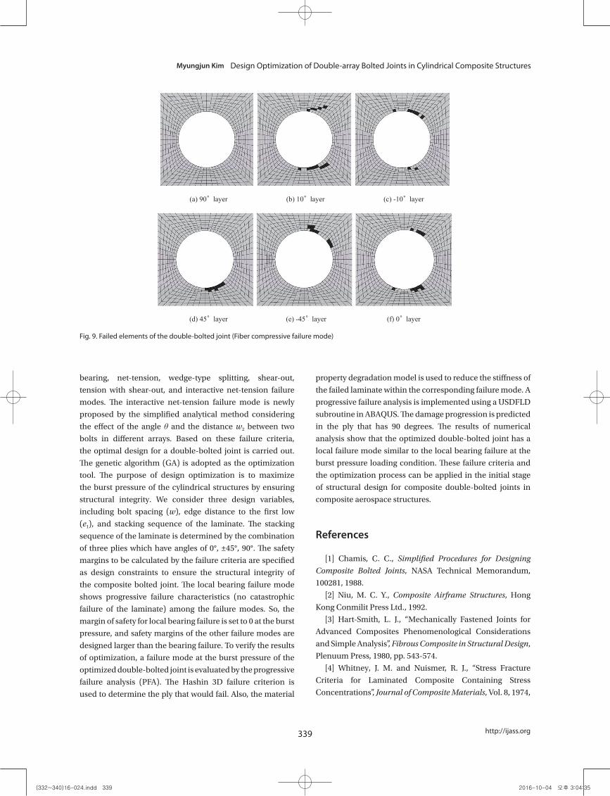
the corresponding failure mode. Fig. 9 shows the damage progression in the composite bolted joint.
Fig. 9. Failed elements of the double-bolted joint (Fiber compressive failure mode)
6. Conclusions
In this paper, design optimization is performed for the double-bolted joint in cylindrical composite
structures by using the simplified analytical method. For the mechanical fastened joint with a zigzag
double bolt arrangement, the failure criteria are defined for the six failure modes: local bearing, net-
tension, wedge-type splitting, shear-out, tension with shear-out, and interactive net-tension failure
modes. The interactive net-tension failure mode is newly proposed by the simplified analytical
method considering the effect of the angle and the distance w2 between two bolts in different
arrays. Based on these failure criteria, the optimal design for a double-bolted joint is carried out. The
(19)
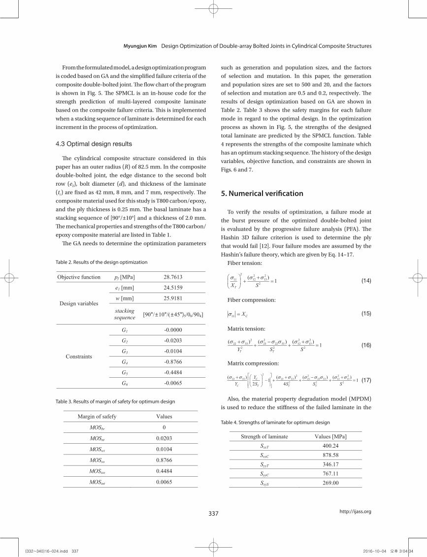
From these failure mechanisms, the progressive failure
analysis for the optimized double-bolted joint is carried
out. Finite element analysis is performed using ABAQUS/
Standard. A total of 134,960 eight node linear brick elements
(C3D8 in ABAQUS) are employed to model the composite
double-bolted joint. To consider the contact between bolt
and hole, the surface to surface contact condition is applied
to the contact faces of each of them. The 3D finite element
model and the boundary and loading conditions are
represented in Fig. 8.
A progressive failure analysis is implemented using
a USDFLD subroutine in ABAQUS which allows the
material properties to be a direct function of predefined
field variables. Stresses are called into the subroutine at
the current increment and used to evaluate the failure of
composite lamina. If a failure occurs, the field variable
is updated and the material properties are then reduced
according to the corresponding failure mode. Fig. 9 shows
the damage progression in the composite bolted joint.
6. Conclusions
In this paper, design optimization is performed for the
double-bolted joint in cylindrical composite structures by
using the simplified analytical method. For the mechanical
fastened joint with a zigzag double bolt arrangement, the
failure criteria are defined for the six failure modes: local
16
Fig. 6. History of design variables
Fig. 7. History of Objective function and constraints
Fig. 8. FE model and boundary/loading conditions of double-bolted joint
0 100 200 300 400 50020
20.5
21
21.5
22
22.5
23
23.5
24
24.5
e 1[mm
]
Generation0 100 200 300 400 50025
26
27
28
29
30
31
32
33
w[m
m]
Generation
0 100 200 300 400 50010
15
20
25
30
Generation
p f [MPa
]
0 100 200 300 400 500-1
-0.8
-0.6
-0.4
-0.2
0
0.2
Generation
Cons
train
ts
G1 G2 G3 G4 G5 G6
Fig. 6. History of design variables
16
Fig. 6. History of design variables
Fig. 7. History of Objective function and constraints
Fig. 8. FE model and boundary/loading conditions of double-bolted joint
0 100 200 300 400 50020
20.5
21
21.5
22
22.5
23
23.5
24
24.5
e 1[mm
]
Generation0 100 200 300 400 50025
26
27
28
29
30
31
32
33
w[m
m]
Generation
0 100 200 300 400 50010
15
20
25
30
Generation
p f [MPa
]
0 100 200 300 400 500-1
-0.8
-0.6
-0.4
-0.2
0
0.2
Generation
Cons
train
ts
G1 G2 G3 G4 G5 G6
Fig. 7. History of objective function and constraints
16
Fig. 6. History of design variables
Fig. 7. History of Objective function and constraints
Fig. 8. FE model and boundary/loading conditions of double-bolted joint
0 100 200 300 400 50020
20.5
21
21.5
22
22.5
23
23.5
24
24.5
e 1[mm
]
Generation0 100 200 300 400 50025
26
27
28
29
30
31
32
33w
[mm
]
Generation
0 100 200 300 400 50010
15
20
25
30
Generation
p f [MPa
]
0 100 200 300 400 500-1
-0.8
-0.6
-0.4
-0.2
0
0.2
Generation
Cons
train
ts
G1 G2 G3 G4 G5 G6
Fig. 8. FE model and boundary/loading conditions of double-bolted joint
(332~340)16-024.indd 338 2016-10-04 오후 3:04:35
339
Myungjun Kim Design Optimization of Double-array Bolted Joints in Cylindrical Composite Structures
http://ijass.org
bearing, net-tension, wedge-type splitting, shear-out,
tension with shear-out, and interactive net-tension failure
modes. The interactive net-tension failure mode is newly
proposed by the simplified analytical method considering
the effect of the angle θ and the distance w2 between two
bolts in different arrays. Based on these failure criteria,
the optimal design for a double-bolted joint is carried out.
The genetic algorithm (GA) is adopted as the optimization
tool. The purpose of design optimization is to maximize
the burst pressure of the cylindrical structures by ensuring
structural integrity. We consider three design variables,
including bolt spacing (w), edge distance to the first low
(e1), and stacking sequence of the laminate. The stacking
sequence of the laminate is determined by the combination
of three plies which have angles of 0°, ±45°, 90°. The safety
margins to be calculated by the failure criteria are specified
as design constraints to ensure the structural integrity of
the composite bolted joint. The local bearing failure mode
shows progressive failure characteristics (no catastrophic
failure of the laminate) among the failure modes. So, the
margin of safety for local bearing failure is set to 0 at the burst
pressure, and safety margins of the other failure modes are
designed larger than the bearing failure. To verify the results
of optimization, a failure mode at the burst pressure of the
optimized double-bolted joint is evaluated by the progressive
failure analysis (PFA). The Hashin 3D failure criterion is
used to determine the ply that would fail. Also, the material
property degradation model is used to reduce the stiffness of
the failed laminate within the corresponding failure mode. A
progressive failure analysis is implemented using a USDFLD
subroutine in ABAQUS. The damage progression is predicted
in the ply that has 90 degrees. The results of numerical
analysis show that the optimized double-bolted joint has a
local failure mode similar to the local bearing failure at the
burst pressure loading condition. These failure criteria and
the optimization process can be applied in the initial stage
of structural design for composite double-bolted joints in
composite aerospace structures.
References
[1] Chamis, C. C., Simplified Procedures for Designing
Composite Bolted Joints, NASA Technical Memorandum,
100281, 1988.
[2] Niu, M. C. Y., Composite Airframe Structures, Hong
Kong Conmilit Press Ltd., 1992.
[3] Hart-Smith, L. J., “Mechanically Fastened Joints for
Advanced Composites Phenomenological Considerations
and Simple Analysis”, Fibrous Composite in Structural Design,
Plenuum Press, 1980, pp. 543-574.
[4] Whitney, J. M. and Nuismer, R. J., “Stress Fracture
Criteria for Laminated Composite Containing Stress
Concentrations”, Journal of Composite Materials, Vol. 8, 1974,
17
(a) 90° layer (b) 10° layer (c) -10° layer
(d) 45° layer (e) -45° layer (f) 0° layer
Fig. 9. Failed elements of the double-bolted joint (Fiber compressive failure mode)
Fig. 9. Failed elements of the double-bolted joint (Fiber compressive failure mode)
(332~340)16-024.indd 339 2016-10-04 오후 3:04:35

DOI: http://dx.doi.org/10.5139/IJASS.2016.17.3.332 340
Int’l J. of Aeronautical & Space Sci. 17(3), 332–340 (2016)
pp. 253-265.
[5] Chang, F. K. and Scott, R. A., “Strength of Mechanically
Fastened Composite Joints”, Journal of Composite Materials,
Vol. 16, 1982, pp. 470–494.
[6] Chang, F. K. and Scott, R. A., “Failure of Composite
Laminates Containing Pin Loaded Holes-Method of
Solution”, Journal of Composite Materials, Vol. 18, 1984, pp.
255–278.
[7] Hollmann, K., “Failure Analysis of Bolted Composite
Joints Exhibiting In-plane Failure Modes”, Journal of
Composite Materials, Vol. 30, 1996, pp. 358-383.
[8] Choi, J. H. and Chun, Y. J., “Failure Load Prediction
of Mechanically Fastened Composite Joint”, Journal of
Composite Materials, Vol. 37, No. 24, 2003, pp. 2163–2177.
[9] Park, J. S., Hong, C. S., Hwang, T. K., Jung, B. and Cho, W.
M., “Stress Analysis of Bolted Joint of Cylindrical Composite
Structure”, Journal of the Korean Society for Aeronautical and
Space Sciences, Vol. 20, No. 2, 1992, pp. 55-66.
[10] Holland, J. H., Adaptation in Natural and Artificial
System, University of Michigan Press, 1975.
[11] Godberg, Genetic Algorithms in Search, Optimization,
and Machine Learning, Pearson Education, 2013.
[12] Hashin, Z., “Failure Criteria for Unidirectional Fibre
Composites”, ASME Journal of Applied Mechanics, Vol. 47,
No. 2, 1980, pp. 329-334.
[13] Tay, T. E., Liu, G., Tan, V. B. C., Sun, X. S. and Pham,
D. C., “Progressive Failure Analysis of Composites”, Journal of
Composite Materials, Vol. 42, 2008, pp. 1921-1966.
(332~340)16-024.indd 340 2016-10-04 오후 3:04:36