Design Opimization of UHPC Waffle Deck Panels · n the girder ement of a ft) long. It five standa...
11
1 DESIGN OPTIMIZATION OF BRIDGE DECKS WITH PRECAST UHPC WAFFLE PANELS Ebadollah Honarvar 1 , Sri Sritharan 2 , Jon Matthews Rouse 3 , and Sriram Aaleti 4 1 Ph.D, Dept. of Civil, Construction, and Environmental Engineering, Iowa State Univ., Ames, IA 50011. Email: [email protected] 2 Wilson Engineering Professor, Dept. of Civil, Construction, and Environmental Engineering, Iowa State Univ., Ames, IA 50011. Email: [email protected] 3 Senior Lecturer, Dept. of Civil, Construction, and Environmental Engineering, Iowa State Univ., Ames, IA 50011. Email: [email protected] 4 Assistant Professor, Dept. of Civil, Construction, and Environmental Engineering, Univ. of Alabama, Tuscaloosa, AL 35487. Email: [email protected] ABSTRACT The first full-depth, precast, ultra-high performance concrete (UHPC) waffle panels have been designed and implemented in a bridge replacement project to utilize accelerated bridge construction (ABC) and increase bridge deck longevity. After satisfactory performance of bridge deck under moving loads, this paper examines the options to optimize the bridge deck design to minimize the UHPC volume and associated labor costs. Using the full-scale finite-element model of the bridge, an optimization of the waffle panels was undertaken by varying the number of ribs as well as spacing between the ribs. An optimized panel was achieved by reducing the interior ribs per panel from four to two, or zero, in the longitudinal direction and six to two in the transverse direction, without compromising the panel’s structural performance. Using the recommended optimized design, it was shown that the UHPC volume can be reduced by 13.4% compared to the design completed for the bridge, thereby significantly reducing the construction costs. Author keywords: Precast; Waffle panel; Ultra-high performance concrete (UHPC); Bridge deck; Optimization; Design First International Interactive Symposium on UHPC – 2016
-
Upload
phunghuong -
Category
Documents
-
view
213 -
download
0
Transcript of Design Opimization of UHPC Waffle Deck Panels · n the girder ement of a ft) long. It five standa...

1
DESIGN OPTIMIZATION OF BRIDGE DECKS WITH PRECAST UHPC WAFFLE PANELS
Ebadollah Honarvar1, Sri Sritharan2, Jon Matthews Rouse3, and Sriram Aaleti4
1Ph.D, Dept. of Civil, Construction, and Environmental Engineering, Iowa State Univ., Ames, IA 50011. Email: [email protected] 2Wilson Engineering Professor, Dept. of Civil, Construction, and Environmental Engineering, Iowa State Univ., Ames, IA 50011. Email: [email protected] 3Senior Lecturer, Dept. of Civil, Construction, and Environmental Engineering, Iowa State Univ., Ames, IA 50011. Email: [email protected] 4Assistant Professor, Dept. of Civil, Construction, and Environmental Engineering, Univ. of Alabama, Tuscaloosa, AL 35487. Email: [email protected]
ABSTRACT
The first full-depth, precast, ultra-high performance concrete (UHPC) waffle panels have been designed and implemented in a bridge replacement project to utilize accelerated bridge construction (ABC) and increase bridge deck longevity. After satisfactory performance of bridge deck under moving loads, this paper examines the options to optimize the bridge deck design to minimize the UHPC volume and associated labor costs. Using the full-scale finite-element model of the bridge, an optimization of the waffle panels was undertaken by varying the number of ribs as well as spacing between the ribs. An optimized panel was achieved by reducing the interior ribs per panel from four to two, or zero, in the longitudinal direction and six to two in the transverse direction, without compromising the panel’s structural performance. Using the recommended optimized design, it was shown that the UHPC volume can be reduced by 13.4% compared to the design completed for the bridge, thereby significantly reducing the construction costs.
Author keywords: Precast; Waffle panel; Ultra-high performance concrete (UHPC); Bridge
deck; Optimization; Design
First International Interactive Symposium on UHPC – 2016
2
1. Introduction
Current bridge infrastructure challenges in the U.S. caused by growing traffic volume and an increasing number of aging, structurally deficient or obsolete bridges, demand accelerated bridge construction (ABC) methods and structural systems with increased longevity. The Better Roads Bridge Inventory survey (2009) indicated that the deterioration of the deck is a leading cause for obsolete and/or a deficient inspection rating of the bridges. Due to the excellent durability and structural properties of ultra-high performance concrete (UHPC), it has been receiving more attention by bridge engineers as a means to increase the bridge service life and reduce life-cycle costs by requiring less maintenance (Piotrowski and Schmidt 2012).
The dense matrix of UHPC leads to enhance durability properties over the conventional concrete as measured by freeze-thaw tests, scaling tests, permeability tests, resistance to alkali-silica reactivity (ASR), abrasion tests, and carbonation (Russell and Graybeal 2013). Hence, the use of UHPC in bridge deck application prevents the detrimental solutions from infiltrating into the matrix when it is designed to be crack free and exposed to the environmental deterioration.
However, currently the UHPC’s initial unit quantity cost far surpasses that of conventional concrete, which underscores the need for economy in its use, by optimizing the design as emphasized by the FHWA-HRT-13-060 report (Russell and Graybeal 2013). Additionally, utilizing precast concrete deck panels is gaining significant interest among several State Departments of Transportation (DOTs) for both new and replacement bridges, as a system promoting ABC (Terry et al. 2009). Previously, Issa and Yousif (2000) and Berger (1983) showed that the use of precast, full-depth concrete deck systems can significantly accelerate bridge construction/rehabilitation, resulting in minimized delays and disruptions to the community.
For the reasons noted above, the State of Iowa, which has the third highest number of deficient bridges in the U.S. (ASCE 2013), has been actively implementing UHPC in its infrastructure. The Iowa DOT led the nation with the implementation of UHPC Pi girders (Keierleber et al. 2008) and the development of an H-shaped UHPC precast pile for foundation applications (Vande Voort et al. 2008). In one of the recent projects sponsored by the FHWA Highways for LIFE (HfL), by combining the advantages of UHPC with those of precast deck systems, a bridge system with prefabricated UHPC waffle deck panels and field-cast UHPC connections was developed. Following a successful laboratory evaluation of the structural performance of waffle deck panels and suitable connections (Aaleti et al. 2011), a full-scale, 19.2 m (63 ft) long, single span demonstration bridge with full depth prefabricated UHPC waffle deck panels was constructed on Dahlonega Road in Wapello County, Iowa. This replacement bridge is the first UHPC waffle deck bridge in the U.S. and is used to demonstrate the deployment of the UHPC waffle deck technology from fabrication through construction.
After verifying satisfactory performance of bridge deck under moving loads (Honarvar et al. 2016), this paper investigates cost effective design alternatives to the deck design completed for Dahlonega Road Bridge with an intention of reducing UHPC volume and the waffle deck cost. An optimization of the waffle panels was undertaken by varying the number of ribs as well as the spacing between the ribs, using a finite-element model (FEM) of the bridge developed using ABAQUS. The design guidelines proposed for the implementation of UHPC waffle deck systems in new and replacement bridges, by Aaleti et al. 2013, were given consideration in the optimization study. Furthermore, girder live load moment distribution factors (DFs) of the optimized designs were calculated and compared with the current design to ensure that the
First International Interactive Symposium on UHPC – 2016

optimal superstr
2. B
The sinWapelloprefabri(Index oThe brid
A swide antransvertwo cellongitudFigures ribs. Eabottom, No.19 (dowels panels wconnectthe gap with thewere pro
Fig
designs woructure wou
Bridge Des
ngle-span, two County, Ioicated, full-of Beam Stadge plan viesingle UHPCnd 2.44 m rse used thrlls in a padinal directi
2b and 2c.ach rib is 10
and 140 m(No.6, db = with a diam
were connection, panel’sbetween th
e panels, a sovided.
gure 1. Dahlon
ould not alteld act effect
scription
wo-lane Daowa, is 9.14-depth, precandards 201ew, cross secC waffle pan(8 ft) long
roughout thianel have tions, respec. Hereafter, 01 mm (4 in
mm (5.5 in.) 0.75 in., db
meter of 25 mcted across ts dowel bar
he panels washear pocke
nega Road Br
er the distribtively as an
ahlonega Ro4 m (33 ft) cast concret11) placed action, and cnel of the D
g, as shownis documenthree interioctively, andthe interior
n.) wide at tdeep. Long
b is diametermm (1 in.) the length ors were tiedas filled witet connectio
ridge: (a) pla
bution of lointegral sys
oad Bridge,wide and 1
te panels inat a center-tconstruction Dahlonega Rn in Figure nt are relativor ribs and
d two exterir ribs in eacthe top withgitudinal anr of bar) bawere used t
of the bridged together wth UHPC. In
on and a wa
n view; (b) cr
oads betweestem.
, the replac19.20 m (63nstalled on to-center disphotos are
Road Bridge2a. Note t
ve to the brd two interior ribs in ch cell of ah a gradual nd transversars at the topto reinforcee using a tra
with additionn order to m
affle panel-t
ross section; (
en the girder
cement of a3 ft) long. Itfive standa
stance of 2.shown in Fi
e deck is 5.5that the termridge, not thrior ribs ineach direct
a panel are decrease toe ribs were p and the b the field-caansverse joinal transvermake the girto-girder lon
(c) constructi
rs and that t
an existing t consists o
ard Iowa “B33 m (7 ft aigure 1.
5 m (16 ft anms, longituhe panel. Ean the transvtion, as illureferred to 76 mm (3 both reinfo
ottom. Stainast UHPC jint connectiorse reinforcerders fully cngitudinal c
on; Note: 1 ft
3
the bridge
bridge in of fourteen B” girders and 4 in.).
nd 2.5 in.) udinal and ach of the verse and
ustrated in simply as in.) at the
orced with nless steel oints. The on. In this ement and composite
connection
t = 0.305 m
First International Interactive Symposium on UHPC – 2016
F
3. N
A 3D noreinforcpropertilinear 3Dand theABAQUaccordapanels a
Thewith Y
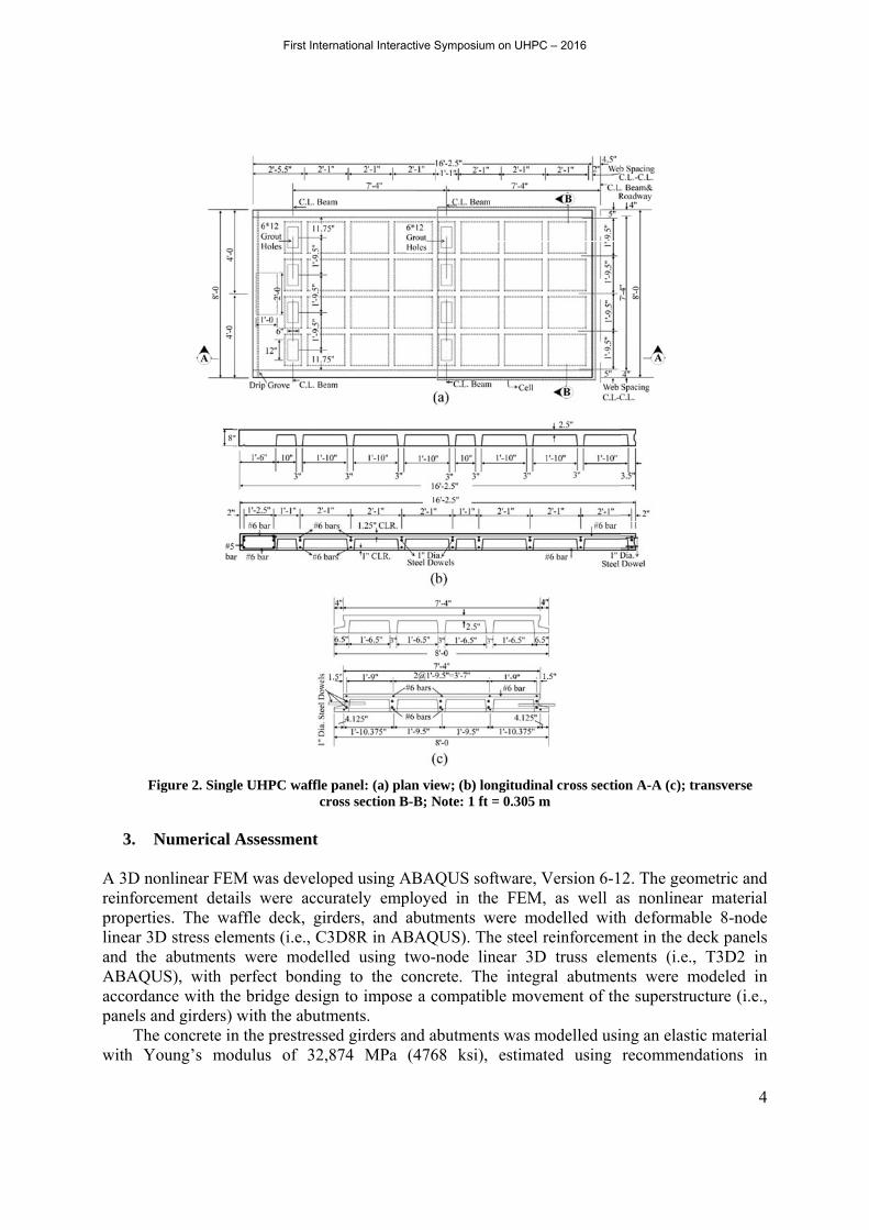
Figure 2. Sing
Numerical
onlinear FEcement detaies. The waD stress ele
e abutmentsUS), with pance with thand girders) e concrete in
Young’s mo
le UHPC waf
Assessmen
M was deveails were acaffle deck, ements (i.e.,s were modperfect bon
he bridge dewith the ab
n the prestreodulus of 3
ffle panel: (a)cross sectio
nt
eloped usingccurately emgirders, an C3D8R in delled using
nding to theesign to impbutments. essed girder32,874 MP
) plan view; (bn B-B; Note:
g ABAQUSmployed in
nd abutmentABAQUS)g two-nodee concrete. pose a comp
rs and abutmPa (4768 k
b) longitudina1 ft = 0.305 m
S software, Vn the FEM,ts were mo). The steel re linear 3D
The integrpatible move
ments was mksi), estimat
al cross sectiom
Version 6-1, as well a
odelled withreinforceme
D truss elemral abutmenement of th
modelled usited using
on A-A (c); tr
2. The geomas nonlinearh deformabent in the dements (i.e., nts were mhe superstruc
ing an elastirecommend
4
ransverse
metric and r material
ble 8-node eck panels
T3D2 in modeled in
cture (i.e.,
ic material dations in
First International Interactive Symposium on UHPC – 2016
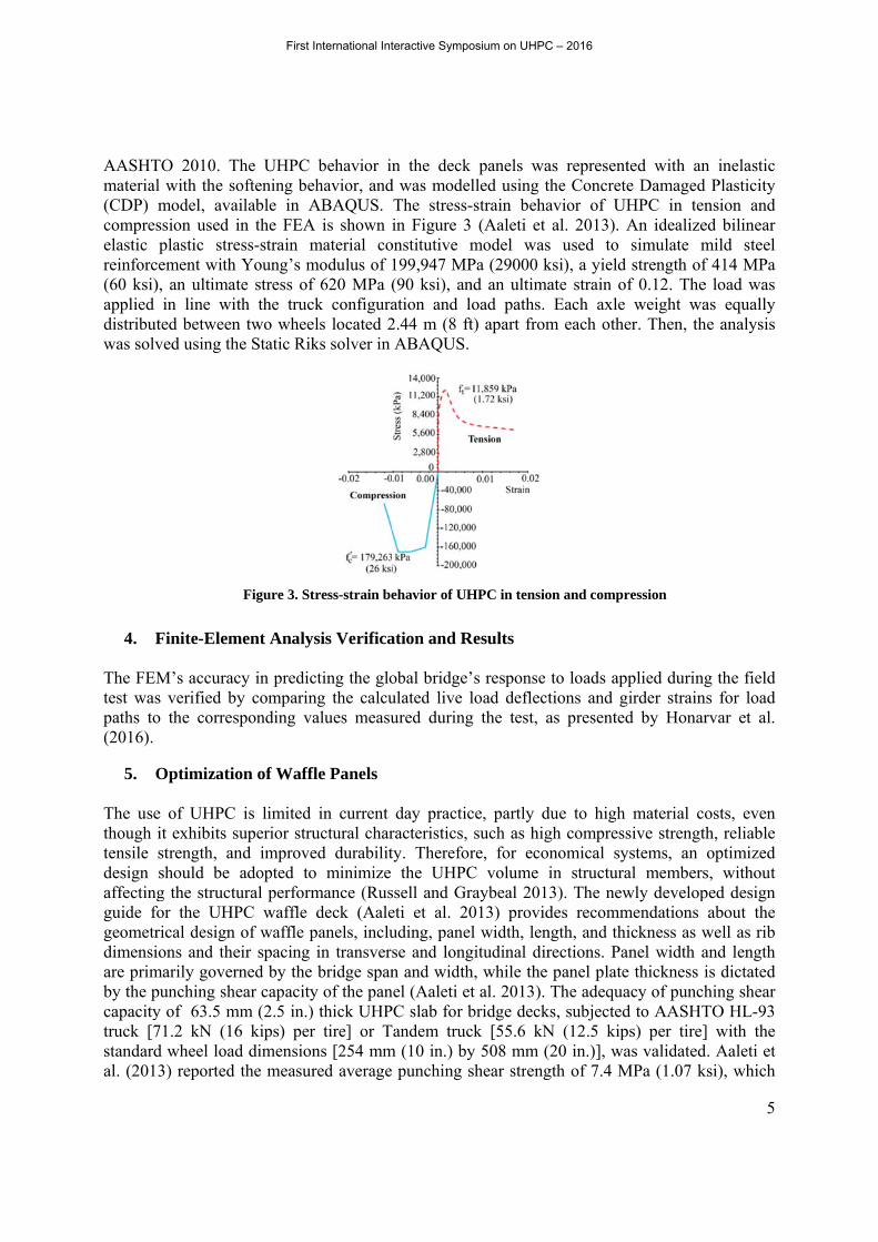
AASHTmaterial(CDP) compreselastic reinforc(60 ksi)applied distributwas solv
4. F
The FEMtest waspaths to(2016).
5. O
The usethough tensile design affectingguide fogeometrdimensiare primby the pcapacitytruck [7standardal. (201
TO 2010. Tl with the smodel, avassion used plastic stre
cement with), an ultima
in line wited betweenved using th
Finite-Elem
M’s accuracs verified bo the corres
Optimizatio
e of UHPCit exhibits sstrength, anshould be g the struct
for the UHPrical design ions and themarily goverpunching shy of 63.5 m71.2 kN (16d wheel load3) reported
The UHPC oftening be
ailable in Ain the FEAess-strain m
h Young’s mate stress of ith the trucn two wheehe Static Rik
Figure 3. St
ment Analy
cy in predicby comparinsponding va
on of Waffl
C is limited superior strund improveadopted to
tural performPC waffle of waffle peir spacing rned by the ear capacity
mm (2.5 in.)6 kips) perd dimensionthe measur
behavior inehavior, andABAQUS.
A is shown material comodulus of f 620 MPa (ck configuraels located 2ks solver in
tress-strain be
sis Verifica
cting the glong the calcualues measu
fle Panels
in current uctural chared durabilito minimize mance (Rusdeck (Aale
panels, incluin transverbridge span
y of the pan thick UHP
r tire] or Tns [254 mmred average
n the deckd was modeThe stress-in Figure 3
onstitutive m199,947 MP(90 ksi), anation and l2.44 m (8 ftABAQUS.
ehavior of UH
ation and R
obal bridge’ulated live lured during
day practicracteristics, ty. Therefor
the UHPCssell and Greti et al. 20uding, panese and longn and width
nel (Aaleti etPC slab for bTandem trucm (10 in.) by
punching s
k panels walled using t-strain beha (Aaleti etmodel wasPa (29000 knd an ultimaload paths. t) apart from
HPC in tensio
Results
’s response load deflectg the test, a
ce, partly dsuch as higre, for ecoC volume iraybeal 201013) providl width, len
gitudinal dirh, while the t al. 2013). bridge deckck [55.6 kNy 508 mm (shear streng
as representthe Concreteavior of UHal. 2013). A
s used to ksi), a yield ate strain ofEach axle
m each othe
on and compr
to loads aptions and gas presented
due to high gh compressnomical syin structura3). The newdes recommngth, and thirections. Papanel plateThe adequa
ks, subjectedN (12.5 kip(20 in.)], wagth of 7.4 M
ted with ane Damaged HPC in tenAn idealizesimulate mstrength of
f 0.12. Theweight wa
er. Then, th
ression
plied duringgirder straind by Honar
material cosive strength
ystems, an al memberswly developmendations ickness as w
anel width ae thickness iacy of punchd to AASHTps) per tire]as validated
MPa (1.07 k
5
n inelastic Plasticity
nsion and ed bilinear mild steel f 414 MPa e load was as equally he analysis
g the field s for load rvar et al.
osts, even h, reliable optimized s, without ped design about the
well as rib and length is dictated hing shear TO HL-93 ] with the
d. Aaleti et ksi), which
First International Interactive Symposium on UHPC – 2016

6
was nearly 2.3 times the estimated value using the equation recommended by Harris and Wollmann (2005). Therefore, both punching shear capacity values reported by Aaleti et al. (2013) and Harris and Wollmann (2005) are greater than the punching shear that would be experienced by a bridge deck when subjected to AASHTO truck.
In the context of minimizing the volume of UHPC for waffle deck panels, the number of ribs and ribs spacing can be potentially altered to reduce the UHPC volume. The remaining structural properties of components, such as panel dimensions and deck reinforcement, were retained during optimization. In this study, two designs were investigated as alternatives to the waffle panel used in the Dahlonega Road Bridge, with the prospect of reducing the UHPC volume in line with the design guideline (Aaleti et al. 2013). The guideline recommends a maximum spacing of 0.91 m (36 in.) for the ribs in both longitudinal and transverse directions. However, these limits were slightly exceeded due to geometric constraints of the panel in the alternative designs.
The first alternative design reduced the number of ribs per cell, to one, in both longitudinal and transverse directions with a transverse and longitudinal rib spacing of 0.95 m (37.5 in.) and 1.05 m (41.5 in.), respectively. In the second alternative design, the longitudinal rib was eliminated as the load was primarily transferred in the transverse direction for the bridge deck. Therefore, the two longitudinal ribs in the original panel design were removed, while one transverse rib was retained. The elimination of the longitudinal ribs transformed the waffle slab effectively into the ribbed slab. It should be noted that the rib reinforcement [one continuous No. 19 (No. 6) reinforcing bar at the top and bottom of each rib] as well as rib tapering along the depth [101 mm (4 in.) wide at the top with a gradual decrease to 76 mm (3 in.) at the bottom] in the proposed designs were kept the same as the original design. Hereafter, the recommended designs are referred to as redesign 1 (i.e., the design with one rib in both directions) and redesign 2 (i.e., the ribbed slab). Panel geometrical details for the original design, and redesigns one and two, are demonstrated in Figure 4.
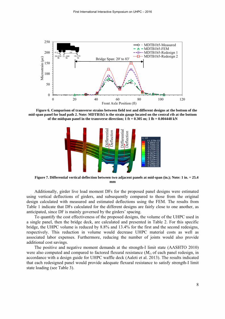
The field test results indicated that peak strains in the deck panels occurred primarily for load path two (center of traffic lane) and load path three (straddling bridge centerline). Thus, evaluating the performance of the alternative designs, the analysis was conducted for these load paths. The location of the maximum transverse strain at the bottom of each panel for load path two is demonstrated in Figure 4. The maximum estimated live load tensile strains at the bottom of the panel for the three designs are reported in Figure 5. It can be seen that the original design produced the smallest transverse strains, while redesign 2 produced the highest transverse strains. However, these strains are still lower than the UHPC cracking strain, thereby demonstrating satisfactory structural performance of the two proposed alternative designs. As expected, the longitudinal strains are fairly similar for the different designs. The strain distributions for the different designs at the critical location along the bottom of the mid-span panel were compared in Figure 6. The results indicate that the proposed redesigns do not significantly change the strain distribution trend when compared to the original design and field measurements.
In the design guide (Aaleti et al. 2013), it was recommended to provide at least one interior longitudinal rib between two consecutive girder lines in addition to the exterior longitudinal ribs to ensure adequate connections between two adjacent panels. However, the load transfer in the current bridge seems to be in the transverse direction rather than the longitudinal direction. Hence, the adequacy of the connection between the two adjacent panels was analytically examined for redesign 2. As an extreme case, it was assumed that no bonding existed between the two adjacent panels except for the regions where there were exterior longitudinal ribs, which
First International Interactive Symposium on UHPC – 2016

providedbetweenplaced affectingat the m
Figload pa
d connectivn the two adin the midg the structu
mid-span is il
gure 4. Panel ath 2 at the m
0
50
100
150
200
250
300
Mic
rost
rain
(με
)vity. The andjacent pan
d-span paneural performllustrated in
transverse amid-span pane
Figure 5. M
103 115
6
Original D
Load Path 2-TLoad Path 3-TLoad Path 2-LLoad Path 3-L
nalysis shownels was 0.0el. Consequmance of then Figure 7.
nd longitudinel: (a) origina
Maximum estim
61 62
Design
TransverseTransverseLongitudinalLongitudinal
wed that th0002 m (0.0uently, the e panels. Th
nal cross sectial design; (b)
mated live loa
140 130
6
Redesig
Crac
he maximum01 in.), whe
longitudinahe deflected
ions juxtaposRedesign 1; (
ad strains for
63 65
gn 1
cking strain o
m differentien the rear aal rib can shape of th
sed with trans(c) Redesign 2
r load paths 2
168 158
Redesi
of UHPC= 250
ial vertical axle of the be removede two adjac
sverse strain r2; Note: 1 ft =
2 and 3
63 65
ign 2
0 µε
7
deflection truck was d without ent panels
results for = 0.305 m
First International Interactive Symposium on UHPC – 2016
Figmid-spa
Figu
Add
using vdesign cTable 1anticipa
To a singlebridge, respectiassociataddition
Thewere alsaccordathat eacstate loa
gure 6. Compan panel for l
of the m
ure 7. Differe
ditionally, gvertical deflcalculated w indicate th
ated, since Dquantify the
e panel, thenthe UHPC vvely. This ted labor enal cost savie positive aso computed
ance with a dch redesigneading (see T
0
50
100
150
200
250
0
Mic
rost
rain
(με
)
parison of tranoad path 2. N
midspan panel
ential vertical
girder live llections of with measu
hat DFs calcDF is mainlye cost effectn the bridgevolume is rreduction
xpenses. Fuings. and negatived and compdesign guided panel woTable 3).
20
nsverse strainNote: MDTB1l in the transv
l deflection be
load momengirders, an
ured and esculated for ty governed btiveness of e deck, are reduced by 8
in volumeurthermore,
e moment dpared to factde for UHPCould provide
40
Bri
ns between fie1b5 is the straverse directio
etween two admm
nt DFs for nd subsequetimated defthe differenby the girdethe proposecalculated
8.8% and 1e would de, reducing
demands at tored flexurC waffle dece adequate f
60Front Axle P
dge Span: 20'
eld test and dain gauge locan; 1 ft = 0.305
djacent panel
the proposeently compaflections us
nt designs arers’ spacing.ed designs, tand present3.4% for thecrease UHthe number
the strengtral resistancck (Aaleti eflexural resi
80Position (ft)
to 83'
different desigated on the ce5 m; 1 lb = 0.
ls at mid-span
ed panel deared to thosing the FEre fairly clo. the volume ted in Tabl
he first and tHPC materir of joints
th-I limit stace (Mr) of eaet al. 2013). istance to sa
0 10
MDTB1b5-MDTB1b5-MDTB1b5-MDTB1b5-
gns at the botentral rib at t004448 kN
n (in.); Note:
esigns were ose from thEM. The resose to one a
of the UHPe 2. For thithe second ial costs as
would als
ate (AASHach panel reThe resultsatisfy streng
00 1
-Measured-FEM-Redesign 1-Redesign 2
8
ttom of the the bottom
1 in. = 25.4
estimated he original sults from another, as
PC used in is specific redesigns, s well as o provide
TO 2010) edesign, in s indicated gth-I limit
120
First International Interactive Symposium on UHPC – 2016
9
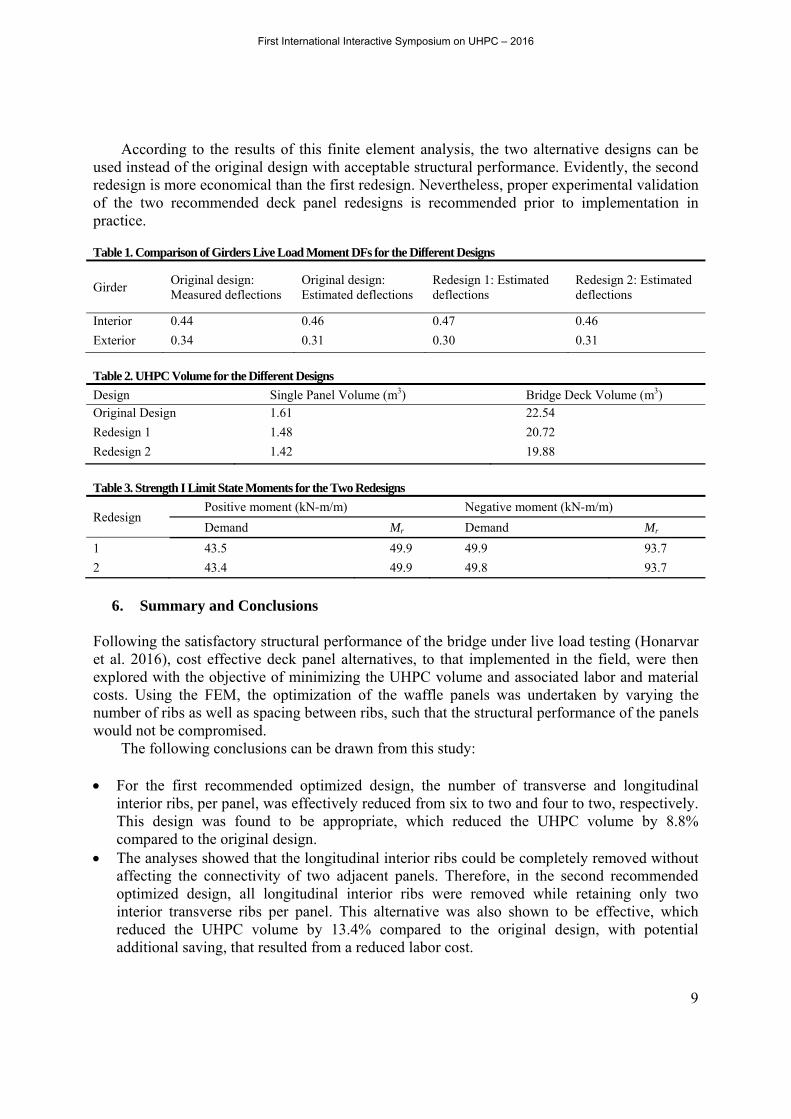
According to the results of this finite element analysis, the two alternative designs can be used instead of the original design with acceptable structural performance. Evidently, the second redesign is more economical than the first redesign. Nevertheless, proper experimental validation of the two recommended deck panel redesigns is recommended prior to implementation in practice.
Table 1. Comparison of Girders Live Load Moment DFs for the Different Designs
Girder Original design: Measured deflections
Original design: Estimated deflections
Redesign 1: Estimated deflections
Redesign 2: Estimated deflections
Interior 0.44 0.46 0.47 0.46
Exterior 0.34 0.31 0.30 0.31
Table 2. UHPC Volume for the Different Designs
Design Single Panel Volume (m3) Bridge Deck Volume (m3) Original Design 1.61 22.54
Redesign 1 1.48 20.72
Redesign 2 1.42 19.88
Table 3. Strength I Limit State Moments for the Two Redesigns
Redesign Positive moment (kN-m/m) Negative moment (kN-m/m)
Demand Mr Demand Mr
1 43.5 49.9 49.9 93.7
2 43.4 49.9 49.8 93.7
6. Summary and Conclusions
Following the satisfactory structural performance of the bridge under live load testing (Honarvar et al. 2016), cost effective deck panel alternatives, to that implemented in the field, were then explored with the objective of minimizing the UHPC volume and associated labor and material costs. Using the FEM, the optimization of the waffle panels was undertaken by varying the number of ribs as well as spacing between ribs, such that the structural performance of the panels would not be compromised.
The following conclusions can be drawn from this study:
For the first recommended optimized design, the number of transverse and longitudinal interior ribs, per panel, was effectively reduced from six to two and four to two, respectively. This design was found to be appropriate, which reduced the UHPC volume by 8.8% compared to the original design.
The analyses showed that the longitudinal interior ribs could be completely removed without affecting the connectivity of two adjacent panels. Therefore, in the second recommended optimized design, all longitudinal interior ribs were removed while retaining only two interior transverse ribs per panel. This alternative was also shown to be effective, which reduced the UHPC volume by 13.4% compared to the original design, with potential additional saving, that resulted from a reduced labor cost.
First International Interactive Symposium on UHPC – 2016

10
For both optimized deck panel designs, the live load moment distribution factors and strain distributions remained the same as those obtained for the original design.
7. References Aaleti, S., Petersen, B., and Sritharan, S. "Design guide for precast ultra-high-performance
concrete waffle deck panel system, including connections,"FHWA-HIF-13-032, Bridge Engineering Center Iowa State University, Ames, IA, 2013.
Aaleti, S. and Sritharan, S. “Design of ultrahigh-performance concrete waffle deck for accelerated bridge construction,” Transportation Research Record, 2014, 2406, 12–22.
Aaleti, S., Sritharan, S., Bierwagen, D., and Wipf, T. J. "Structural behavior of waffle bridge deck panels and connections of precast UHPC: experimental evaluation," Transportation Research Record: Journal of the Transportation Research Board, 2011, 82-92.
AASHTO. LRFD bridge design specifications, Washington, DC, 2010. American Society of Civil Engineers. "Report card for America's infrastructure," 2013,
available at http://www.infrastructurereportcard.org/a/documents/2013-Report-Card.pdf [ Accessed Jul. 24, 2014].
Bakht, B. "A guide for field testing of bridges," American Society of Civil Engineers, Committee on Safety of Bridges, New York, N.Y., 1980.
Berger, R. "Full-Depth modular precast prestressed bridge decks," Transportation Research Record,1983, 903 , 52-59.
Better Roads Bridge Inventory (2009). "Bridge inventory 2009 state of bridges," Available at http://www.betterroads.com/better-bridges-bridge-inventory-2009-state-of-bridges [ Accessed Aug. 13, 2014].
Graybeal, B. "Ultra-high-performance concrete connections for precast concrete bridge decks," Precast/Pretressed Concrete Institute Journal, 2014, 59(4): 48-62.
Harris, D. K., and Wollmann, C. L. “Characterization of the punching shear capacity of thin ultra-high performance concrete slabs,” VTRC 05-CR26, Virginia Transportation Research Council, Charlottesville, VA, 2005.
Honarvar, E., Sritharan, S., Rouse, J., and Aaleti, S. “Bridge decks with precast UHPC waffle panels: a field evaluation and design optimization,” ASCE Journal of Bridge Engineering, 2016, 21 (1): 1-13.
Iowa Department of Transportation. "Index of Beam Standards," 2011, Available at http://www.iowadot.gov/bridge/standards/english/EnglishBeams.pdf [Accessed Apr. 10, 2014].
Issa, M., and Yousif, A. "Experimental behavior of full-depth precast concrete panels for bridge rehabilitation," ACI Structural Journal, 2000, 97(3): 397-407.
Keierleber, B., Bierwagen, D., Wipf, T., and Abu-Hawash, A. (2008). "Design of Buchanan County, Iowa Bridge using UHPC and pi-girder cross section," Proc., Precast/Prestressed Concrete Institute National Bridge Conference, 2008, Paper 27, Orlando, FL.
Piotrowski, S., and Schmidt, M. "Life cycle cost analysis of a UHPC bridge on example of two bridge refurbishment designs," Proc., Hipermat 3rd International Symposium on UHPC and Nanotechnology for High Performance Construction Materials, Kassel University Press, Kassel,Germany, 2012, 957-964.
Russell, H., and Graybeal, B. "Ultra-high performance concrete: a state-of-the-art report for the bridge community," FHWA-HRT-13-060, Henry G. Russell, Inc.Engineering Consultant, McLean, VA, 2013.
First International Interactive Symposium on UHPC – 2016

11
Vande Voort, T., Suleiman, M., and Sritharan, S. "Design and performance verification of UHPC piles for deep foundations," Iowa State University – Center for Transportation Research and Education, Ames, IA, 2008.
Wipf, T. J., Klaiber, W., and Hockerman, S. "Precast concrete elements for accelerated bridge construction," IHRB Project TR-561, Bridge Engineering Center Iowa State Unive., Ames, IA, 2009.
Working Committee on the Safety of Bridges."A guide for the field testing of bridges," ASCE, New York, 1980.
First International Interactive Symposium on UHPC – 2016


![Put your left hand in the air!500334]YEAR_1_AND_2... · Mountains Mermaid Island twinkl uality Standa twinkt.com . twinkl uality Standa 00 0 . Title: PowerPoint Guidance Author: Twinkl](https://static.fdocuments.us/doc/165x107/600681dba9d5e0261e4db168/put-your-left-hand-in-the-air-500334year1and2-mountains-mermaid-island.jpg)