Design of Virtual Three-dimensional Instruments for Sound ...
113
Design of Virtual Three-dimensional Instruments for Sound Control by Axel G.E. Mulder Drs., Rijks Universiteit Groningen, 1989 a thesis submitted in partial fulfillment of the requirements for the degree of Doctor of Philosophy in the School of Kinesiology c Axel G.E. Mulder 1998 SIMON FRASER UNIVERSITY October 1998 All rights reserved. This work may not be reproduced in whole or in part, by photocopy or other means, without the permission of the author.
Transcript of Design of Virtual Three-dimensional Instruments for Sound ...

Design of Virtual Three-dimensional Instrumentsfor Sound Control
by
Axel G.E. Mulder
Drs., Rijks Universiteit Groningen, 1989
a thesis submitted in partial fulfillment
of the requirements for the degree of
Doctor of Philosophy
in the School
of
Kinesiology
c© Axel G.E. Mulder 1998
SIMON FRASER UNIVERSITY
October 1998
All rights reserved. This work may not be
reproduced in whole or in part, by photocopy
or other means, without the permission of the author.
APPROVAL
Name: Axel G.E. Mulder
Degree: Doctor of Philosophy
Title of thesis: Design of Virtual Three-dimensional Instruments for Sound
Control
Examining Committee: Dr. Ted Milner
Chair
Dr. Tom Calvert
Senior Supervisor
Dr. Christine MacKenzie
School of Kinesiology
Barry Truax
Department of Communication
Martin Gotfrit
School for the Contemporary Arts
Dr. David Sturman
MaMaMedia Inc.
Dr. Bruce Clayman
Dean, Faculty of Graduate Studies
Date Approved:
ii
Abstract
An environment for designing virtual instruments with 3D geometry has been prototyped and ap-
plied to real-time sound control and design. It enables a sound artist, musical performer or composer
to design an instrument according to preferred or required gestural and musical constraints instead
of constraints based only on physical laws as they apply to an instrument with a particular geome-
try. Sounds can be created, edited or performed in real-time by changing parameters like position,
orientation and shape of a virtual 3D input device. The virtual instrument can only be perceived
through a visualization and acoustic representation, or sonification, of the control surface. No haptic
representation is available.
This environment was implemented using CyberGloves, Polhemus sensors, an SGI Onyx and by
extending a real-time, visual programming language called Max/FTS, which was originally designed
for sound synthesis. The extension involves software objects that interface the sensors and software
objects that compute human movement and virtual object features. Two pilot studies have been
performed, involving virtual input devices with the behaviours of a rubber balloon and a rubber
sheet for the control of sound spatialization and timbre parameters.
Both manipulation and sonification methods affect the naturalness of the interaction. Informal
evaluation showed that a sonification inspired by the physical world appears natural and effective.
More research is required for a natural sonification of virtual input device features such as shape,
taking into account possible co-articulation of these features. While both hands can be used for
manipulation, left-hand-only interaction with a virtual instrument may be a useful replacement for
and extension of the standard keyboard modulation wheel. More research is needed to identify
and apply manipulation pragmatics and movement features, and to investigate how they are co-
articulated, in the mapping of virtual object parameters. While the virtual instruments can be
adapted to exploit many manipulation gestures, further work is required to reduce the need for
technical expertise to realize adaptations. Better virtual object simulation techniques and faster
sensor data acquisition will improve the performance of virtual instruments.
The design environment which has been developed should prove useful as a (musical) instrument
prototyping tool and as a tool for researching the optimal adaptation of machines to humans.
iii
Acknowledgments
First of all I want to thank Tom Calvert. His indefatigable support and encouragement concerning
the research presented in this dissertation have been crucial for its success and exceptionally generous.
If it weren’t for Tom, this research might never have happened.
Many thanks are due to the other supervisors on my committee, Barry Truax and Christine
MacKenzie for all the discussions, support and guidance.
An important part of the work was done in Japan from February 1997 until March 1998. I
would like to thank Ryohei Nakatsu, president of the Media Integration and Communications labo-
ratories and Kenji Mase, head of department 2 for inviting me to pursue my work at the Advanced
Telecommunication Research institute in Kyoto, Japan.
Sidney Fels, with whom I closely collaborated in Japan, needs special mention. It was his true
partnership and passion for the project that made the difference. Way to go Sid ! Let’s keep moving
this project into the next century.
Among the many people who have helped me with various important, urgent, difficult, interest-
ing or other things during this PhD process I would like to address special thanks to Lyn Bartram,
Parveen Bawa, Leslie Bishko, Jean Blackall, Gail Brow, Armin Bruderlin, Frank Campbell, John
Dickinson, Tameyuki Etani, Mel Frank, Koujiro Fujii, Dave Goodman, Martin Gotfrit, Evan Gra-
ham, Yumiko Honjo, Kana Itoh, Chris Ivens, Sandra Johnson, Rieko Kadobayashi, Laurie Klak,
Kaoru Kobayashi, Maria Lantin, Roberto “Gulliver” Lopez, Sang Mah, Frank Manuel, Rob Bal-
lantyne, Ron Marteniuk, Shona McLean, Ted Milner, Kazzushi Nishimoto, Miho Nishimura, Haruo
Noma, Yasuyuki Sumi, Yugo Takeuchi, Glen Tibbits, Naoko Tosa, Owen Underhill and Dan Weeks.
Thank you all for your help, suggestions and guidance.
I am grateful to the Natural Sciences and Engineering Research Council and Simon Fraser
University for providing financial support.
Last but not least I would like to thank the PhD examining committee for their comments and
advice.
iv

Contents
Abstract . . . . . . . . . . . . . . . . . . . . . . . . . . . . . . . . . . . . . . . . . . iii
Acknowledgments . . . . . . . . . . . . . . . . . . . . . . . . . . . . . . . . . . . . . iv
1 Introduction . . . . . . . . . . . . . . . . . . . . . . . . . . . . . . . . . . . . . 3
2 Performer and Instrument . . . . . . . . . . . . . . . . . . . . . . . . . . . . . 5
2.1 Analysis of Performer and Instrument . . . . . . . . . . . . . . . . . . 5
2.1.1 Defining Gesture . . . . . . . . . . . . . . . . . . . . . . . . . 6
2.1.2 Defining Control Surface . . . . . . . . . . . . . . . . . . . . 6
2.1.3 Performer-Instrument Compatibility . . . . . . . . . . . . . . 7
2.1.4 Human Factors Context and Gestural Communication Context 8
2.1.5 Music and Performing Arts Context . . . . . . . . . . . . . . 9
2.2 Review of Related Research . . . . . . . . . . . . . . . . . . . . . . . . 9
2.2.1 Touch Controllers . . . . . . . . . . . . . . . . . . . . . . . . 11
2.2.2 Expanded Range Controllers . . . . . . . . . . . . . . . . . . 11
2.2.3 Immersive Controllers . . . . . . . . . . . . . . . . . . . . . . 14
2.3 Design of Gestural Constraints for Musicians . . . . . . . . . . . . . . 20
2.3.1 Current Methods . . . . . . . . . . . . . . . . . . . . . . . . . 20
2.3.2 Virtual Musical Instruments . . . . . . . . . . . . . . . . . . 22
2.3.3 Research Objectives . . . . . . . . . . . . . . . . . . . . . . . 23
3 VMI Design . . . . . . . . . . . . . . . . . . . . . . . . . . . . . . . . . . . . . 24
3.1 System Analysis . . . . . . . . . . . . . . . . . . . . . . . . . . . . . . 24
3.1.1 Task Analysis . . . . . . . . . . . . . . . . . . . . . . . . . . 24
3.1.2 Requirements . . . . . . . . . . . . . . . . . . . . . . . . . . . 26
3.2 The Performer . . . . . . . . . . . . . . . . . . . . . . . . . . . . . . . 27
3.2.1 Hand Movements . . . . . . . . . . . . . . . . . . . . . . . . 27
v
3.2.2 Pragmatics . . . . . . . . . . . . . . . . . . . . . . . . . . . . 29
3.3 The Instrument . . . . . . . . . . . . . . . . . . . . . . . . . . . . . . . 30
3.3.1 Sensors and Display . . . . . . . . . . . . . . . . . . . . . . . 30
3.3.2 Intelligent Computing . . . . . . . . . . . . . . . . . . . . . . 31
3.3.3 Real-time Computing . . . . . . . . . . . . . . . . . . . . . . 32
3.3.4 Sonification . . . . . . . . . . . . . . . . . . . . . . . . . . . . 32
4 VMI Implementation . . . . . . . . . . . . . . . . . . . . . . . . . . . . . . . . 34
4.1 Environment . . . . . . . . . . . . . . . . . . . . . . . . . . . . . . . . 35
4.1.1 Sensors . . . . . . . . . . . . . . . . . . . . . . . . . . . . . . 35
4.1.2 Computing Platform . . . . . . . . . . . . . . . . . . . . . . . 36
4.1.3 Display . . . . . . . . . . . . . . . . . . . . . . . . . . . . . . 36
4.2 Computations . . . . . . . . . . . . . . . . . . . . . . . . . . . . . . . . 36
4.2.1 Method . . . . . . . . . . . . . . . . . . . . . . . . . . . . . . 36
4.2.2 Implementation . . . . . . . . . . . . . . . . . . . . . . . . . 38
4.3 VMI Prototypes . . . . . . . . . . . . . . . . . . . . . . . . . . . . . . 41
4.3.1 Rubber Sheet . . . . . . . . . . . . . . . . . . . . . . . . . . . 42
4.3.2 Rubber Balloon . . . . . . . . . . . . . . . . . . . . . . . . . 43
5 VMI Evaluation . . . . . . . . . . . . . . . . . . . . . . . . . . . . . . . . . . . 46
5.1 Data Acquisition . . . . . . . . . . . . . . . . . . . . . . . . . . . . . . 46
5.2 Manipulation . . . . . . . . . . . . . . . . . . . . . . . . . . . . . . . . 47
5.2.1 Rubber Sheet . . . . . . . . . . . . . . . . . . . . . . . . . . . 47
5.2.2 Rubber Balloon . . . . . . . . . . . . . . . . . . . . . . . . . 48
5.3 Sonification . . . . . . . . . . . . . . . . . . . . . . . . . . . . . . . . . 49
5.4 Visualization . . . . . . . . . . . . . . . . . . . . . . . . . . . . . . . . 49
5.5 Adaptation . . . . . . . . . . . . . . . . . . . . . . . . . . . . . . . . . 50
5.6 Engineering . . . . . . . . . . . . . . . . . . . . . . . . . . . . . . . . . 50
5.7 Summary . . . . . . . . . . . . . . . . . . . . . . . . . . . . . . . . . . 51
5.8 Recommendations . . . . . . . . . . . . . . . . . . . . . . . . . . . . . 52
6 Conclusion . . . . . . . . . . . . . . . . . . . . . . . . . . . . . . . . . . . . . 55
Appendix: Operating Instructions . . . . . . . . . . . . . . . . . . . . . . . . . . . 58
Appendix: Max/FTS Object Reference . . . . . . . . . . . . . . . . . . . . . . . . 73
Appendix: Video Documentation . . . . . . . . . . . . . . . . . . . . . . . . . . . . 96
Bibliography . . . . . . . . . . . . . . . . . . . . . . . . . . . . . . . . . . . . . . . 97
vi
List of Figures
2.1 A model of musical performance. . . . . . . . . . . . . . . . . . . . . . . . . . . 5
2.2 The I-Cube System Digitizer and a few sensors. Courtesy Infusion Systems Ltd.
[103]. . . . . . . . . . . . . . . . . . . . . . . . . . . . . . . . . . . . . . . . . . 10
2.3 The aXiO. Courtesy Brad Cariou [16]. . . . . . . . . . . . . . . . . . . . . . . . 12
2.4 The “Hands”. Courtesy Michel Waisvisz [111]. . . . . . . . . . . . . . . . . . . 13
2.5 The Radio Drum. Courtesy William Putnam and R. Benjamin Knapp. [76]. . . . 13
2.6 The Theremin and the Dimension Beamtm. . . . . . . . . . . . . . . . . . . . . 14
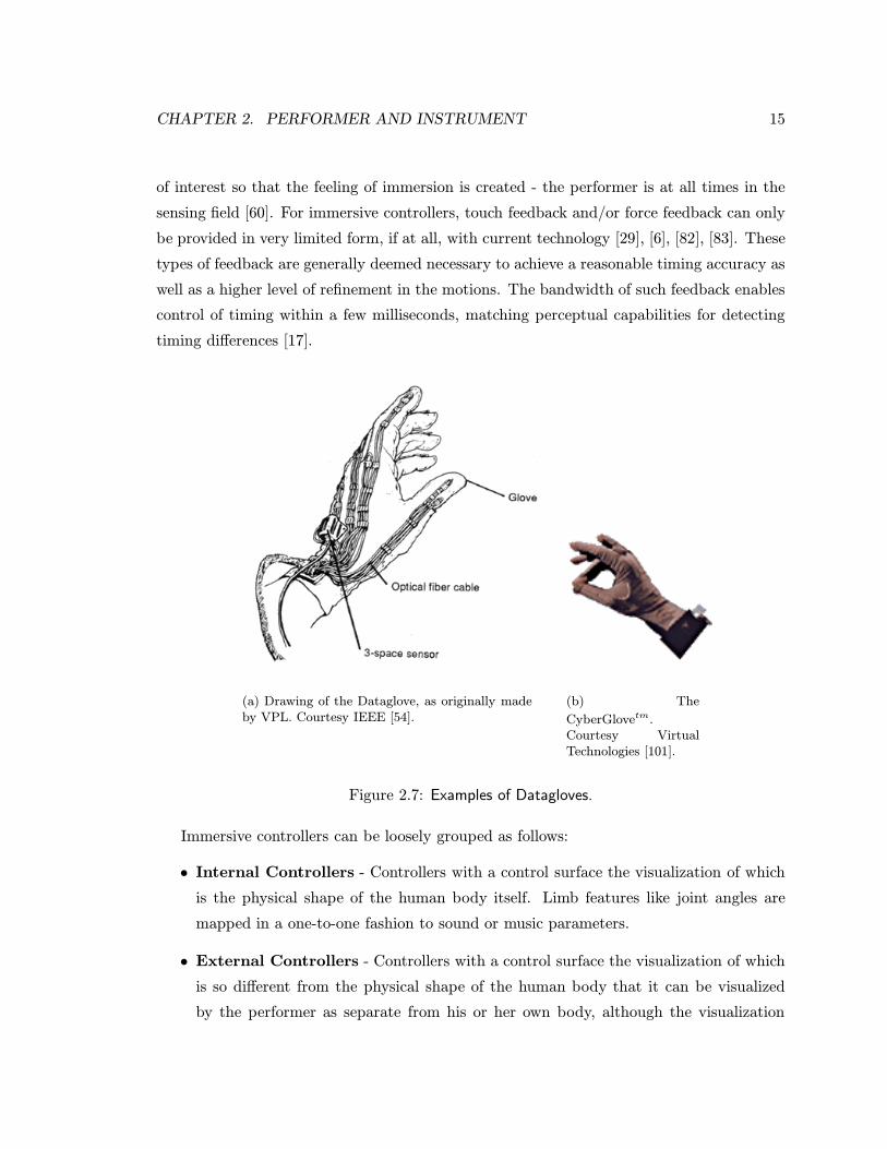
2.7 Examples of Datagloves. . . . . . . . . . . . . . . . . . . . . . . . . . . . . . . 15
2.8 Functional diagram of the bodysuit system. . . . . . . . . . . . . . . . . . . . . 16
2.9 Functional diagram of the GloveTalk II system. Courtesy Sidney Fels [21]. . . . . 18
2.10 Functional diagram of the sign-drum. . . . . . . . . . . . . . . . . . . . . . . . . 19
2.11 The Yamaha Miburitm. Courtesy Yamaha Corp. [107]. . . . . . . . . . . . . . . 20
4.1 Devices used for the VMI environment. The dotted lines represent a 3D virtual
surface which the sound/music composer or performer manipulates. . . . . . . . 35
4.2 Functional diagram of hand movement to sound mapping. Virtual object features
are used as a means to relate hand movement features to sound features. . . . . 37
4.3 The diagrams show mapping at the feature abstraction level, but mapping at
other levels is equally possible. . . . . . . . . . . . . . . . . . . . . . . . . . . . 38
4.4 Typical example of geometric computing using the new Max/FTS position and
orientation objects. This Max patcher takes a list of positions, projects these on
the plane that best fits them, then rotates the plane (with projected positions) and
eliminates z. This patcher enables subsequent fitting of 2D parametric curves
to the x-y coordinates (e.g. the x-y coordinates computed from the positions
marking the thumb and index fingers). . . . . . . . . . . . . . . . . . . . . . . . 40
1
LIST OF FIGURES 2
4.5 Example of the sheet clamped to the index and thumb tips of both hands. . . . . 43
4.6 Example of touching the sheet with both hands. . . . . . . . . . . . . . . . . . . 44
4.7 Example of the balloon clamped to both hands. . . . . . . . . . . . . . . . . . . 44
4.8 Example of touching the balloon with both hands. . . . . . . . . . . . . . . . . . 45
6.1 The Max/FTS patch hand.pat for capturing hand shape, position and orientation
(calibration capabilities omitted for clarity). . . . . . . . . . . . . . . . . . . . . 62
6.2 The Max/FTS patch sheet.pat for creating and controlling a physical simulation
of a rubber sheet. . . . . . . . . . . . . . . . . . . . . . . . . . . . . . . . . . . 63
6.3 The Max/FTS patch sheet-snd.pat for mapping sheet features to sound parameters. 64
6.4 The Max/FTS patch balloon.pat for creating and controlling a physical simulation
of a rubber balloon. . . . . . . . . . . . . . . . . . . . . . . . . . . . . . . . . . 65
6.5 The Max/FTS patch estE.pat for estimating the hand curvature - used to set
the “roundness” of the balloon. . . . . . . . . . . . . . . . . . . . . . . . . . . . 66
6.6 The Max/FTS patch balloon-snd.pat for mapping balloon features to sound pa-
rameters. . . . . . . . . . . . . . . . . . . . . . . . . . . . . . . . . . . . . . . . 67
6.7 The Max/FTS patch synth.pat for polyphonic sound synthesis including all sound
effect parameters. The polySynth object is shown in figure 6.8 as a patch. . . . . 70
6.8 The Max/FTS patch polySynth.pat for polyphonic (8 voices) sound synthesis -
each Voice object is the patch shown in figure 6.9. . . . . . . . . . . . . . . . . 71
6.9 The Max/FTS patcher Voice for synthesis of a single voice. Different timbres
could be created by using different waveforms for the oscillator. . . . . . . . . . 72
Chapter 1
Introduction
Most people assume that learning to play a musical instrument requires a commitment for
many years to develop the motor skills necessary to elicit the desired sounds as well as to
develop an intuition and understanding of the musical structures and idiom of the musical
style of interest.
The research presented in this dissertation is concerned with identifying ways to turn
part of the above assumption around: allowing musical instruments to be adapted to the
motor skills a performer already may have, may prefer or may be limited to. This approach
to the relation between performer and instrument should lead to a greater freedom for the
performer to choose and develop a personal gestural “vocabulary” and, if the performer can
already express these gestures skillfully, a shorter time to musical performance proficiency.
The realization of this approach has been hindered by the physical implementation
of current musical instruments, whether they are acoustic or electronic. Changes in the
layout of keys, valves and sliders of these instruments cannot be brought about easily by a
performer. In the case of acoustic instruments, such changes are also limited by the sound
generating principles around which the instrument is designed.
Electronic musical instruments enabled the separation of the control surface (e.g. keys,
sliders, valves etc.) from the sound generating device (e.g. speakers). This separation
lead to the development of a plethora of “alternate controllers” like the Theremin and the
Dataglove. The latter “hands-free” controllers do not physically restrict hand motion in
any way and hence allow for the implementation of imaginary or virtual control surfaces of
almost unlimited size and of any type of shape.
While this opened up the use of formalized gestures used in sign languages as well as less
3
CHAPTER 1. INTRODUCTION 4
formalized gestures often called gesticulation for the control of sound, such gestures, as they
are intended for conveying structured symbolic information, are best applied during musical
tasks for the control of musical structures, as can be seen in conducting. Where it concerns
the control of sound represented as a multidimensional space of continuous parameters such
as in many synthesis models, manipulation gestures applied to a visually represented control
surface appear more appropriate because these gestures are intended for controlling multiple
continuous variables.
However, the constraints, if any, on the control surface of these “hands-free” controllers
do not facilitate a visualization of the control surface in terms of familiar physical object
features. Generally speaking, to make virtual control surfaces visualizable it is necessary to
maintain a level of continuity from the physical world.
This limitation lead to the notion of a Virtual Musical Instrument (VMI) - a musical
instrument without a physical control surface, but instead a virtual control surface that is
inspired more or less by the physical world. It is the virtual control surface, not any physical
device or sensor that is the focus of attention for any performer. As a VMI is entirely defined
by software any changes to the control surface are a matter of programming, which is in
many cases much easier and forgiving than changing hardware components.
This dissertation presents a design environment for modifying and creating VMIs that
use a sculpting metaphor in its literal sense. Thus, the interaction with these VMIs during
performance, in composing or for sound design is called sound sculpting.
Dissertation Outline
Chapter 2, drawing from work in music, engineering and ergonomics identifies in detail
(in)compatibility issues between performer and instrument. Chapter 3 subsequently carves
out a path to close the gap between the two: what boundary conditions for the system design
can be defined based on human behaviour, human perception and engineering experience ?
It is in chapter 4 that we get down to the details: how is the design environment actually
implemented and what VMI prototypes have been explored. Chapter 5 discusses the results
of this design experiment - the conclusion in chapter 6 places a summary of this evaluation
in the larger context of the fields drawn from in chapter 2, as well as outlines future work.
This dissertation is available on the world wide web [55]. For more information related
to this dissertation and for links to other publications by the author look up
http://www.cs.sfu.ca/∼amulder/personal/vmi.
Chapter 2
Performer and Instrument
intent
motor system
auditorysense
sound generation
musical instrument
performer
vision
control surface
processing
central nervous system
visuali-sation
intent
motor system
auditory sense
audience
vision
centralnervoussystem
proprio-ception
sensors actuators
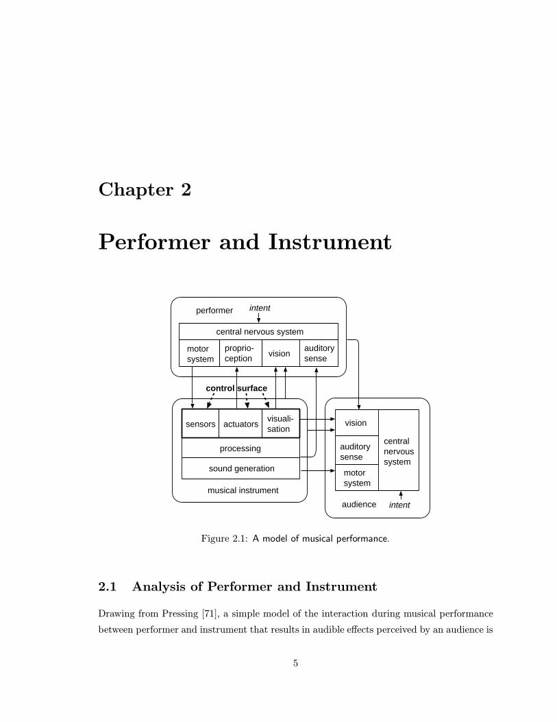
Figure 2.1: A model of musical performance.
2.1 Analysis of Performer and Instrument
Drawing from Pressing [71], a simple model of the interaction during musical performance
between performer and instrument that results in audible effects perceived by an audience is
5
CHAPTER 2. PERFORMER AND INSTRUMENT 6
given in figure 2.1. Visual and proprioceptive feedback (tactile and force feedback) and com-
munication are included. For the sake of giving humans credit for being so unpredictable,
intent is indicated. The fact that musical performance can be represented in different ways
must be taken into account when modeling musical performance. Reference to an auditory
process as “hearing”, for instance, implies a different representation than does reference
to the same process as “listening”. Similarly with respect to the motor system, the terms
“moving” and “gesturing” reflect different representations of the performance process. Two
performance forms, conducting and instrumental performance represent the two extremes in
terms of abstraction. The performance form of conducting, i.e. the control of musical struc-
tures, is often described in terms of symbolically structured gesturing, while instrumental
performance, i.e. the control and processing of sounds through the manipulation of physical
materials, is often described in terms of simultaneous continuous motions of multiple limbs.
2.1.1 Defining Gesture
The word gesture has been used in place of posture and vice versa. The tendency however,
is to see gesture as dynamic and posture as static. The notion of a musical gesture that
at the time it occurs involves no actual human movement but merely refers to it is quite
common. Obviously, musical expression is intimately connected with human movement,
hence the existence of such an idiom. In the following, a hand gesture and hand movement
are both defined as the motions of fingers, hands and arms. Hand posture is defined as the
position of the hand and fingers at one instant in time. However, hand posture and gesture
describe situations where hands are used as a means to communicate to either machine or
human. Empty-handed gestures and free-hand gestures are generally used to indicate use
of the hands for communication purposes without physical manipulation of an object.
2.1.2 Defining Control Surface
The control surface, when visualized, is a physical or virtual surface that, when (virtual)
forces are applied with body parts like the hands, identifies all the human movements the
instrument responds to. In more practical terms, it consists of sensors for human movement
capture, actuators for tactile as well as force feedback yielding a haptic representation and
last but not least a visual representation. The control surface outputs data that represents
the movements and gestures. These data are turned into sound variations after processing.
CHAPTER 2. PERFORMER AND INSTRUMENT 7
The control surface may change shape, position or orientation as a result of the application
of these forces. For example, the control surface can be such that it requires a set of touching
movements such as used for piano playing or constrained reaching movements such as used
in Theremin performance (see section 2.2.2). Note that, as in the case of the Theremin, the
control surface visualization may not be visible either as physical matter or virtually, on a
graphical display. Also, as is the case with the Theremin, the visualization of the control
surface does not need to be identical to the visual representation of the musical instrument.
In the case of conducting, the visual representation of the instrument would be the orchestra
or ensemble, which representation is very different from the control surface. In conducting,
the control surface is very difficult, perhaps impossible to visualize.
2.1.3 Performer-Instrument Compatibility
Due to the configuration of the control surface, currently available musical instruments
require the learning of specific gestures and movements that are not necessarily compatible
with the preferences and/or capabilities of the performer. Moore defined compatibility
between performer and instrument as “control intimacy”: “Control intimacy determines
the match between the variety of musically desirable sounds produced and the psycho-
physiological capabilities of a practiced performer” [53].
Research to improve this compatibility has resulted in many new musical instrument
designs, many of which make use of alternate means of controlling sound production -
alternate controllers - to connect forms of bodily expression to the creation of sound and
music in innovative ways. There are however two shortcomings common to all traditional
and new musical instruments:
• Inflexibility - Due to age and/or bodily traumas the physical and/or motor control
ability of the performer may change, or his or her gestural vocabulary may change due
to personal interests, social influences and cultural trends. Unless the instrument can
be adapted (and the technical expertise to do so is available), accommodation of these
changes necessitates switching to another instrument. Acquired motor skills may be
lost in the transition, while new learning or familiarization will need to take place.
The capability of currently available musical instruments to adapt to these types of
changes can be greatly expanded [2].
CHAPTER 2. PERFORMER AND INSTRUMENT 8
• Standardization - Most musical instruments are built for persons with demograph-
ically normal limb proportions and functionality. The availability of different sizes of
the violin is an exception that confirms the rule. The capability of musical instru-
ments to accommodate persons with limb proportions and/or functionality outside
the norm is relatively undeveloped. It is safe to say that many musical instrument
designs do not fully exploit the particular or preferred capabilities of the performer,
so that persons whose skills are outside the norm need more time to learn to play a
given instrument if they are able to play it at all.
It follows that there is a need for musical instruments with gestural interfaces that
can adapt by themselves, through “learning” capabilities, or be adapted by the performer,
without specific technical expertise, to the gestures and movements of the performer.
2.1.4 Human Factors Context and Gestural Communication Context
Human factors research addresses subjects like ergonomy, human interfacing, human-machine
communication, human computer interaction, motor control, etc. Gestural communication
research addresses subjects like sign language, non-verbal communication, etc. Human
factors researchers have studied the compatibility between performer and instrument as
interface “naturalness” [65] leading to “transparency” of the interface. Interface aspects
that constitute naturalness are understood to be consistency of the interface (in terms of
its method of operation and appearance) and adaptability (either autonomously by the
instrument or by the user) of the interface to the user’s preferences [84]. For multidimen-
sional control tasks it has been shown that the separability (or integrality) of the dominant
perceptual structure of the task, i.e. whether a user will use dimensions separately and se-
quentially to reach an endpoint in control space, should be reflected by the input device [32].
The research on performer instrument compatibility performed in this context has generally
aimed at improving the usability of the interface [93], [94], for which estimation Shackel [81]
provides four criteria: user learning, ease-of-use, system flexibility and user attitude. The
focus of research performed in this context is on finding a new control surface configuration
or control method that reduces the motor and cognitive load applicable to either specific
groups or all humans, usually by generalizing from experimental research.

CHAPTER 2. PERFORMER AND INSTRUMENT 9
2.1.5 Music and Performing Arts Context
The research performed in the context of music and performing arts has generally viewed
compatibility between performer and instrument from the point of view of the listener, fo-
cusing first on the sounds to create the artistic image that needed to be projected onto the
audience and then on suitable and possible gestural control strategies. Due to the unique-
ness of any artistic piece much of the work on alternate controllers resulted in highly unique
and idiosyncratic controllers. The notion of “effort” ([48] and later amongst others [79]),
deemed by some to arise from a level of performance uncertainty [75], contrasts with the
goal of human factors researchers to increase the “ease-of-use”. It has been suggested that
increasing the “ease-of-use” leads to a loss of expressive power because less effort is required
to perform easier, i.e. less refined, motions [95]. As such, from an artist point of view,
increasing the “ease-of-use” has no value other than changing the performance boundary
defined by the gestural and musical constraints of the instrument. Many artists strongly
believe that it is impossible to perform original sound material and to convey a sense of the
performer’s emotions, without the effort necessary for challenging the performance bound-
ary, regardless of where it may be [40], [33]. However, each performer may have preferences
as to the precise definition of the performance boundary, so as to convey a more personal
artistic statement. This observation lead to the development of musical instruments adapted
to the individual performer, with a performance boundary often uniquely challenging to that
performer [105], [110], [46], [108].
2.2 Review of Related Research
Given the different goals of research carried out within the two clusters of fields outlined
above, research to improve the compatibility between performer and instrument focused on
either or both of the following topics:
• Gestural Range - Some research aims to expand the gestural range of existing in-
struments, to exploit unconventional gestures or movements or unused aspects of con-
ventional gestures, so that the range of adaptation can be expanded, despite the fact
that it would still be limited due to physical laws.
• Adaptability - Some research aims to find specific methods to make the musical
instrument as easily adaptable (performer implements change) or adaptive (instrument

CHAPTER 2. PERFORMER AND INSTRUMENT 10
implements change) as possible.
This research has resulted in the development of a wealth of alternate controllers [67],
[72], [30], [61], [8], [92], either completely new or extrapolated from traditional musical
instruments (e.g. hyperinstruments [46]). To realize larger and larger gestural ranges,
alternate controllers have evolved from those requiring contact with some physical surface
fixed in space to those without almost any such physical contact requirements. In the latter
case the implementation of a suitable haptic representation is very difficult. Unfortunately
the integration of various different controllers is often hindered by physical form and size
as well as MIDI protocol limitations. The I-Cube System (figure 2.2), a modular, user-
configurable sensing environment [103], was inspired by this approach. However, its coverage
of the human gestural range is incomplete as yet. Also, users are required to physically
assemble a controller matching their needs, which often requires significant engineering
skills.
Figure 2.2: The I-Cube System Digitizer and a few sensors. Courtesy Infusion Systems Ltd.[103].
To provide an insight in the range of research carried out, in the following a variety of
controllers will be discussed, varying from touch controllers, to expanded range controllers,
to immersive controllers which impose few or no restrictions to movement but provide no
suitable haptic feedback as yet. Immersive controllers are subdivided in three different
types: internal, external and symbolic controllers.

CHAPTER 2. PERFORMER AND INSTRUMENT 11
2.2.1 Touch Controllers
Most alternate controllers that expand the gestural range still require the performer to touch
a physical control surface, usually fixed in space but sometimes carried around. Although
any of these controllers can be adapted to meet the specific gestural needs or preferences of
an individual performer, such adaptation is limited by the particular physical construction
of the controller. Adaptation beyond these limits requires not only very specific technical
knowledge, but is usually also time consuming. An important advantage of touch controllers
is their ability to provide a haptic representation.
aXiO
A typical example of an alternative controller requiring physical contact is the aXiO (figure
2.3), an ergonomic physical control surface consisting of knobs, sliders and buttons [16]. De-
spite the fact that it was developed within a human factors context and could be designated
an ergonomic controller, the ergonomic features are only evident given a specific gestural
“vocabulary” and posture. Also, any adaptation of this controller would be technically
challenging and time consuming.
2.2.2 Expanded Range Controllers
These controllers may require physical contact in only a limited form, or may not require
physical contact but have a limited range of effective gestures. Despite their expanded
gestural range compared to touch controllers, the performer can always “escape” the control
surface and make movements without musical consequence. The haptic representation of
these controllers is reduced or even absent due to less physical contact.
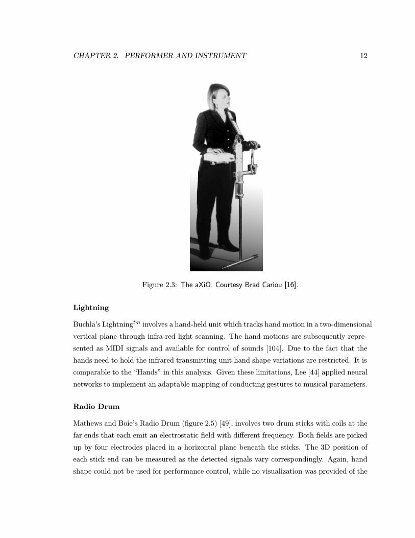
The “Hands”
At STEIM in the Netherlands a number of alternate controllers amongst others the “Hands”
(figure 2.4) were developed [3]. The “Hands” allow the hands to move almost freely in space
- finger motions are restricted to button press motions. Only distance between the hands
is sensed ultrasonically. Also, no visualization of the control surface was implemented.
Therefore it is a hybrid of a controller like the Theremin (see section 2.2.2) and alternate
controllers requiring physical contact like the aXiO.
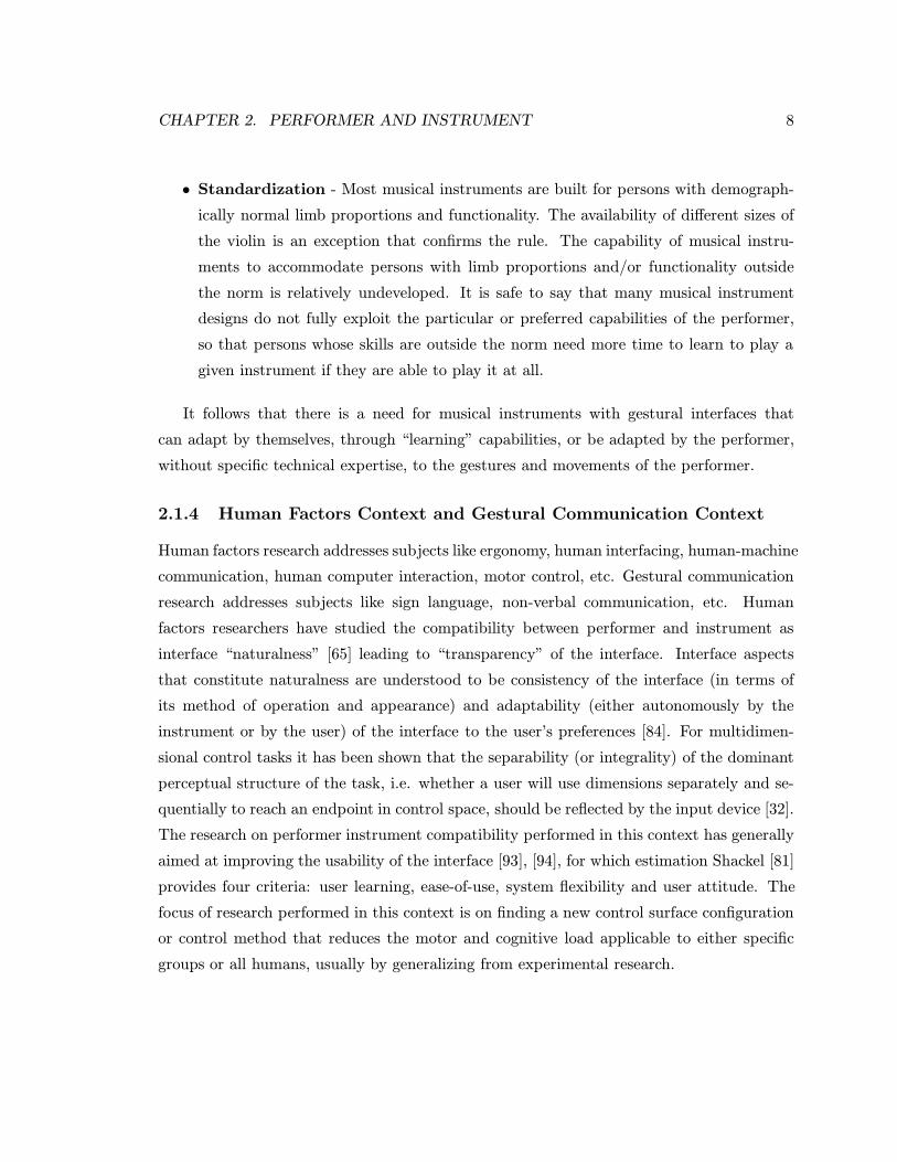
CHAPTER 2. PERFORMER AND INSTRUMENT 12
Figure 2.3: The aXiO. Courtesy Brad Cariou [16].
Lightning
Buchla’s Lightningtm involves a hand-held unit which tracks hand motion in a two-dimensional
vertical plane through infra-red light scanning. The hand motions are subsequently repre-
sented as MIDI signals and available for control of sounds [104]. Due to the fact that the
hands need to hold the infrared transmitting unit hand shape variations are restricted. It is
comparable to the “Hands” in this analysis. Given these limitations, Lee [44] applied neural
networks to implement an adaptable mapping of conducting gestures to musical parameters.
Radio Drum
Mathews and Boie’s Radio Drum (figure 2.5) [49], involves two drum sticks with coils at the
far ends that each emit an electrostatic field with different frequency. Both fields are picked
up by four electrodes placed in a horizontal plane beneath the sticks. The 3D position of
each stick end can be measured as the detected signals vary correspondingly. Again, hand
shape could not be used for performance control, while no visualization was provided of the
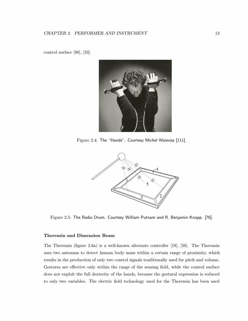
CHAPTER 2. PERFORMER AND INSTRUMENT 13
control surface [80], [33].
Figure 2.4: The “Hands”. Courtesy Michel Waisvisz [111].
Figure 2.5: The Radio Drum. Courtesy William Putnam and R. Benjamin Knapp. [76].
Theremin and Dimension Beam
The Theremin (figure 2.6a) is a well-known alternate controller [19], [50]. The Theremin
uses two antennas to detect human body mass within a certain range of proximity, which
results in the production of only two control signals traditionally used for pitch and volume.
Gestures are effective only within the range of the sensing field, while the control surface
does not exploit the full dexterity of the hands, because the gestural expression is reduced
to only two variables. The electric field technology used for the Theremin has been used
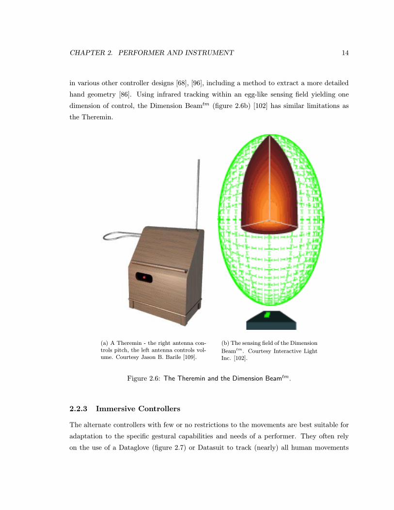
CHAPTER 2. PERFORMER AND INSTRUMENT 14
in various other controller designs [68], [96], including a method to extract a more detailed
hand geometry [86]. Using infrared tracking within an egg-like sensing field yielding one
dimension of control, the Dimension Beamtm (figure 2.6b) [102] has similar limitations as
the Theremin.
(a) A Theremin - the right antenna con-trols pitch, the left antenna controls vol-ume. Courtesy Jason B. Barile [109].
(b) The sensing field of the Dimension
Beamtm. Courtesy Interactive LightInc. [102].
Figure 2.6: The Theremin and the Dimension Beamtm.
2.2.3 Immersive Controllers
The alternate controllers with few or no restrictions to the movements are best suitable for
adaptation to the specific gestural capabilities and needs of a performer. They often rely
on the use of a Dataglove (figure 2.7) or Datasuit to track (nearly) all human movements
CHAPTER 2. PERFORMER AND INSTRUMENT 15
of interest so that the feeling of immersion is created - the performer is at all times in the
sensing field [60]. For immersive controllers, touch feedback and/or force feedback can only
be provided in very limited form, if at all, with current technology [29], [6], [82], [83]. These
types of feedback are generally deemed necessary to achieve a reasonable timing accuracy as
well as a higher level of refinement in the motions. The bandwidth of such feedback enables
control of timing within a few milliseconds, matching perceptual capabilities for detecting
timing differences [17].
(a) Drawing of the Dataglove, as originally madeby VPL. Courtesy IEEE [54].
(b) The
CyberGlovetm.Courtesy VirtualTechnologies [101].
Figure 2.7: Examples of Datagloves.
Immersive controllers can be loosely grouped as follows:
• Internal Controllers - Controllers with a control surface the visualization of which
is the physical shape of the human body itself. Limb features like joint angles are
mapped in a one-to-one fashion to sound or music parameters.
• External Controllers - Controllers with a control surface the visualization of which
is so different from the physical shape of the human body that it can be visualized
by the performer as separate from his or her own body, although the visualization

CHAPTER 2. PERFORMER AND INSTRUMENT 16
may be impossible to implement as a physical shape. Limb features may be complex
(e.g. derived features like distance between two finger tips) and/or these features are
mapped in a complex (e.g. non-linear or many-to-one) way to sound and/or music
parameters.
• Symbolic Controllers - Controllers with a control surface that is, due to its com-
plexity, (almost) impossible to visualize or can only partially be visualized and which
requires formalized gesture sets like sign language and forms of gesticulation such as
used in conducting to operate. Gestural patterns are mapped to structural aspects of
the music.
Atari 1040 STcomputerA/D converter
Lexicon LXP5 effects processor
MIDI
mike8 flex sensors
multiplexer
MIDI mapping software
Figure 2.8: Functional diagram of the bodysuit system.
Internal Controllers
The following describes a preliminary design experiment for the work described in this
dissertation. To experiment with controlling sound effects through whole body movements, a
tightly fitting garment intended for use by dancers was made [58]. The bodysuit incorporated
eight sensors to capture wrist flexion, elbow flexion, shoulder flexion and knee flexion which
were mapped to MIDI messages controlling a sound effects device processing the voice of
the performer (figure 2.8). This controller did not impose any restrictions on the gestural
range, but did not capture all aspects of the movements either, so that effective gestures were
somewhat limited. Nevertheless, immersion was achieved in the sense that the performer
CHAPTER 2. PERFORMER AND INSTRUMENT 17
felt most movements had an effect. The control surface was the performer’s body, each
joint controlling a synthesis parameter like a slider on a synthesis control panel. This
mapping appeared to be very difficult to learn. First of all, human movements often involve
the simultaneous movement of multiple limbs. So, when the intent was to change one or
more specific parameter(s), often other synthesis parameters were co-articulated, i.e. also
changed unintentionally. Perhaps more importantly, the mapping did not encourage use
of any familiar movements like manipulation gestures or simple symbolic gestures or signs.
Instead, the performer was required to learn to move single joints only. An easier way to
deploy this control surface would seem to be to have another performer move the bodysuit
wearer’s body through manipulation gestures.
The Biomuse [38] implements a relation between muscle tension and musical sound by
capturing myo-electric voltages off the human skin with EMG electrodes. The dimension-
ality of the control surface is dependent on the number of EMG electrodes used. When
sufficient electrodes are used this approach results in an immersive controller. The con-
troller requires the performer to focus attention on the tension in the sensed muscles [90],
unless a control surface would be designed that can be visualized with a different shape
than the performer’s body. Otherwise, as with the musical bodysuit, the control surface is
(a part of) the performer’s body and the control surface would seem to be easier to learn
if another performer would move the Biomuse wearer’s body (the Biomuse wearer will have
to resist movement to create muscle tension).
External Controllers
Hartono et al [27] mapped movement parameters captured by a Dataglove to a multi dimen-
sional sound parameter space using neural networks. An adaptation was implemented using
active learning capabilities of the neural networks. This method alleviated the common
problem of requiring the user to provide the entire gesture - sound data set each time a part
of the mapping is changed or expanded. Although the instrument could be adapted almost
entirely to the needs of the performer, no control surfaces were implemented requiring that a
performer had to start from scratch designing a control surface. No visualizations of control
surfaces were provided, so that gestures were limited to simple manipulation gestures or
spatial trajectories.
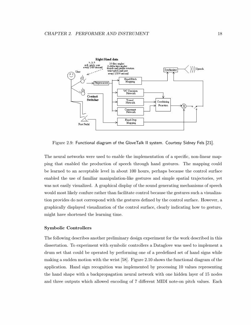
Fels [21], in his implementation of a gesture to speech system (figure 2.9) used neural
network technology and a variety of movement tracking technologies, including a Dataglove.
CHAPTER 2. PERFORMER AND INSTRUMENT 18
Figure 2.9: Functional diagram of the GloveTalk II system. Courtesy Sidney Fels [21].
The neural networks were used to enable the implementation of a specific, non-linear map-
ping that enabled the production of speech through hand gestures. The mapping could
be learned to an acceptable level in about 100 hours, perhaps because the control surface
enabled the use of familiar manipulation-like gestures and simple spatial trajectories, yet
was not easily visualized. A graphical display of the sound generating mechanisms of speech
would most likely confure rather than facilitate control because the gestures such a visualiza-
tion provides do not correspond with the gestures defined by the control surface. However, a
graphically displayed visualization of the control surface, clearly indicating how to gesture,
might have shortened the learning time.
Symbolic Controllers
The following describes another preliminary design experiment for the work described in this
dissertation. To experiment with symbolic controllers a Dataglove was used to implement a
drum set that could be operated by performing one of a predefined set of hand signs while
making a sudden motion with the wrist [58]. Figure 2.10 shows the functional diagram of the
application. Hand sign recognition was implemented by processing 10 values representing
the hand shape with a backpropagation neural network with one hidden layer of 15 nodes
and three outputs which allowed encoding of 7 different MIDI note-on pitch values. Each
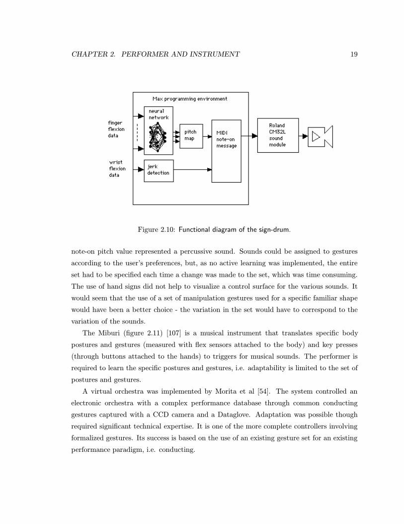
CHAPTER 2. PERFORMER AND INSTRUMENT 19
Figure 2.10: Functional diagram of the sign-drum.
note-on pitch value represented a percussive sound. Sounds could be assigned to gestures
according to the user’s preferences, but, as no active learning was implemented, the entire
set had to be specified each time a change was made to the set, which was time consuming.
The use of hand signs did not help to visualize a control surface for the various sounds. It
would seem that the use of a set of manipulation gestures used for a specific familiar shape
would have been a better choice - the variation in the set would have to correspond to the
variation of the sounds.
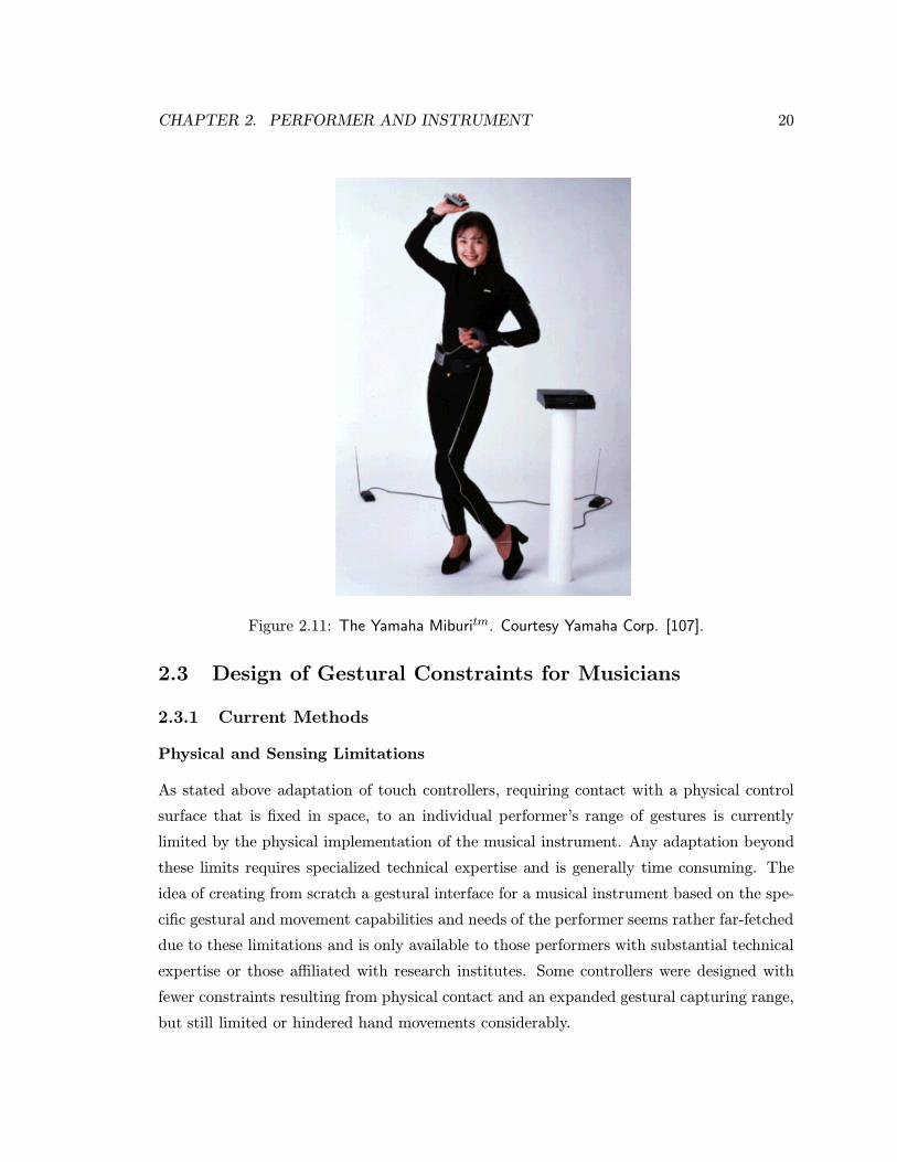
The Miburi (figure 2.11) [107] is a musical instrument that translates specific body
postures and gestures (measured with flex sensors attached to the body) and key presses
(through buttons attached to the hands) to triggers for musical sounds. The performer is
required to learn the specific postures and gestures, i.e. adaptability is limited to the set of
postures and gestures.
A virtual orchestra was implemented by Morita et al [54]. The system controlled an
electronic orchestra with a complex performance database through common conducting
gestures captured with a CCD camera and a Dataglove. Adaptation was possible though
required significant technical expertise. It is one of the more complete controllers involving
formalized gestures. Its success is based on the use of an existing gesture set for an existing
performance paradigm, i.e. conducting.
CHAPTER 2. PERFORMER AND INSTRUMENT 20
Figure 2.11: The Yamaha Miburitm. Courtesy Yamaha Corp. [107].
2.3 Design of Gestural Constraints for Musicians
2.3.1 Current Methods
Physical and Sensing Limitations
As stated above adaptation of touch controllers, requiring contact with a physical control
surface that is fixed in space, to an individual performer’s range of gestures is currently
limited by the physical implementation of the musical instrument. Any adaptation beyond
these limits requires specialized technical expertise and is generally time consuming. The
idea of creating from scratch a gestural interface for a musical instrument based on the spe-
cific gestural and movement capabilities and needs of the performer seems rather far-fetched
due to these limitations and is only available to those performers with substantial technical
expertise or those affiliated with research institutes. Some controllers were designed with
fewer constraints resulting from physical contact and an expanded gestural capturing range,
but still limited or hindered hand movements considerably.
CHAPTER 2. PERFORMER AND INSTRUMENT 21
Visualization of the Control Surface
Although with current technology a suitable haptic representation is very difficult to im-
plement for immersive controllers, they are capable of capturing the entire gestural range
with sufficient accuracy and resolution. Immersive controllers were subsequently used for
musical control tasks. However, in the case of internal controllers confusion arises as the
object acted upon is also the acting object. In the case of external controllers thus far the
visualization of the control surface has been (too) complex or the visualization was unavail-
able, making the use of manipulation gestures more difficult to learn and possibly limiting
the use of such gestures. While a skilled musician does not need to rely on a graphically
displayed control surface visualization, almost all musicians have learned to manipulate the
control surface of their instrument by studying the visual and haptic representation of the
control surface and its behaviour [85]. Hence it can be argued that, if manipulation gestures
are to be used, it should always be possible to visualize and/or imagine the haptic “feel”
of a control surface. If gestures other than manipulation are to be used a visualization
might not be necessary and symbolic controllers may be applicable. While the extraction of
symbolically structured information from formalized gestures like signing is still non-trivial
[59], symbolic controllers are thus far most successful in terms of deploying the maximum
gestural range while being maximally adaptable. But these controllers are not well-suited
for the simultaneous control of multi-dimensional continuous parameter spaces such as used
for the description of sound, because signing involves mainly selection and structuring of
discrete and discontinuous events represented as symbols [51].
Real World Continuity
If the need is to simultaneously control multiple continuous sound parameters, manipulation
gestures may be better suited than gestures for communication of symbol structures. But
the immersive controllers implemented thus far do not facilitate the use of manipulation
gestures. These gestures are much easier executed with respect to a visualization and
haptic representation of the control surface that is reminiscent of physical objects. What is
needed is the ability to create and adapt multidimensional control surfaces that are readily
visualizable and responsive to manipulation gestures. In other words, what is needed is the
ability to create and adapt multidimensional control surfaces that are not too different from
most shapes we handle in day-to-day life.
CHAPTER 2. PERFORMER AND INSTRUMENT 22
2.3.2 Virtual Musical Instruments
The afore going reasoning leads to the following possible solution. The limitations imposed
by physics can be overcome by using sensor technology that tracks the entire hands such as
that used for immersive controllers and virtual environments. Then, in a virtual environment
musical instruments can be created that exist only as software. With good user interfaces, it
will be much easier for performers to program this software and design their own controller
than when faced with the requirement to assemble a controller from (modular) hardware
controller parts. All aspects of such a controller will be programmable and no constraints
will be imposed by acoustic or other physics principles and the performer will not be required
to hold physical components, so it will be maximally adaptable to the needs and capabilities
of an individual performer.
But in order to allow for the effective use of manipulation gestures and similar move-
ments, these instruments must provide a form of continuity with respect to the real world
with a readily visualizable control surface, including a suitable haptic representation. Thus,
the shapes or contours of these musical instruments should be copies of or inspired by the
physical shape or contours of objects in our day-to-day life, yet the mapping to sound pa-
rameters may be very different from acoustic instruments. Such musical instruments are
defined as Virtual Musical Instruments (VMI) [61].
In other words, and from the point of view of a human interacting with a computer, the
idea is to extend the user interface for musical and sound synthesis environments from a 2D
interface (or what is sometimes called 212D due to the presence of a 3D mouse represented
as a 2D pointer on a 2D screen) to a 3D interface where visual and haptic representation
and control space are superimposed.
Prior Art
A lot of work has been done on 212D virtual musical instruments, but very little on 3D vir-
tual musical instruments. This work has not aimed for a maximally adaptable or adaptive
instrument or an environment in which to design such instruments, but instead has focused
mostly on the creation of fixed virtual instantiations of familiar musical instruments like
drums [7], flutes [63], guitars and even a Theremin [7], with all the familiar limitations of
the control surface of the original instrument. In a very few cases researchers or artists
CHAPTER 2. PERFORMER AND INSTRUMENT 23
like Lanier [43] have been able to develop their own variation of a VMI inspired on tradi-
tional musical instruments. Choi et al [18] developed a virtual environment in which 3D
spatial paths were visualized. Tracing these paths (a form of movement closely related to
manipulation gestures) resulted in sound variations. Similar to the work presented in this
dissertation, Modler [52] has recently implemented “behaving virtual musical objects”, sim-
ple 3D graphical objects with which the user can interact using 3D hand movements with
musical results.
2.3.3 Research Objectives
The goal of the work presented in the following chapters was to implement a prototyp-
ing environment for Virtual Musical Instruments, without haptic representation because of
technical limitations, and thereby to gain insight into the following areas:
• Manipulation - What kind of manipulation gestures would be used and what kind
of gestural analysis computations would need to be implemented ?
• Sonification - What recommendations can be made with respect to relating shape,
position and orientation variations to sound and music variations ?
• Visualization - How “real” should the control surface visualization appear and how
should it change in response to manipulation and other gestures by the performer ?
• Adaptation - How should the environment be implemented to enable a maximum of
adaptation of a VMI to/by any performer ?
• Engineering - What engineering feats in terms of sensing, computing and display
need to be accomplished in order to achieve real-time performance with a VMI ?
Chapter 3
VMI Design
Rubine has examined in some detail the performer’s sensori-motor and auditory percep-
tion capabilities so as to formulate requirements for musical instruments given engineering
constraints [78]. Similarly, following the discussion in the previous chapter, the question
arises of what should be the capabilities of a virtual musical instrument. Any treatise of
this subject will be necessarily incomplete, and it also does not fall within the scope of
this dissertation to achieve completeness. Hence, this chapter serves to outline a basis for
implementing a VMI design environment by discussing some of the known boundaries that
delimit the design space of virtual musical instruments without providing a classification
method for VMIs in the same way that Card et al has done for computer input devices [15]
and Nigay et al for multi-modal systems [64].
3.1 System Analysis
The aim is to build musical instruments that allow performers to start learning any given
(traditional or new) form of gesturing in a musical performance setting while they may later
prefer or need to incorporate other forms of gesturing.
3.1.1 Task Analysis
Music involves the simultaneous control of many parameters, the changes in which have to be
precisely timed in order for the music to be considered expressive and aesthetically pleasing.
The activities music composition and sound design are not constrained temporally. Normally
24
CHAPTER 3. VMI DESIGN 25
a composition is first written out, after which a performance of the piece may occur. For
sound design, sound parameters may be adjusted after which the sound may be generated
for evaluation. Thus, based on Sturman [89], the task of performing and composing music
and designing sound can be characterized as follows:
• Degrees of freedom - Musical performance, composition and sound design involve
the control of many parameters. The precise number of degrees of freedom depends
on the type of musical activity. Traditionally they have been pitch, loudness, timbre
(which in itself can involve a few degrees of freedom), expression related parameters
like vibrato and musical structure related parameters like tempo, dynamics and meter.
This list has expanded considerably due to electronic sound synthesis and processing
techniques.
• Task constraints - The musical parameter changes, in some musical styles more so
than others, have to be timed down to milliseconds. Music composition and sound
design are not constrained temporally. Aesthetically, musical activities are highly
constrained, although it is a socio-culturally defined constraint. Instrumental perfor-
mance traditionally imposes a physical constraint as to how and where the performer
can move to achieve musical results. The aim of the research presented in this dis-
sertation is to let performers define this constraint according to their desires and/or
needs.
• Coordination - To compose or perform a musically expressive piece or design the
right sound, many parameter changes have to be coordinated. For example, in classical
music to indicate a climax a pitch increase is accompanied by an increase in loudness
decrease and an increase in vibrato. In sound design, envelope parameter changes
may have to be accompanied by changes in the spectrum of the sound. Instrumental
performance traditionally requires a high level of coordination. For example, in wind
instruments, the opening and closing of multiple valves has to occur at the same time
as changes in reed vibration. As the coordination of certain limbs may be more difficult
for certain performers than for others, the research presented in this dissertation may
lead to a reduction of the need for difficult forms of coordination.
CHAPTER 3. VMI DESIGN 26
• Resolution - Resolution is dependent on human perception. Depending on the mu-
sical or sonic context, perception resolution may vary greatly. Given the right condi-
tions, pitch variations can be perceived as low as 2 cents and loudness variations as
lows as 0.25 dB. In terms of timing resolution, two clicks can be heard as separate
clicks when they are at least 2 ms apart [78].
• Speed - Music is a timed series of audible events. The audible events do not have to
be performed as fast as possible, but simply on time. For music composition or sound
design there is no speed requirement.
• Repeatability - The repeatability of musical performances is dependent on musical
style. For example in jazz music improvisations repeatability is low, while in classical
music repeatability is very high.
3.1.2 Requirements
Although the aim as stated above implies that VMIs should be able to respond to any
specific movement or gesture the performer desires it to respond to, the research can be
limited to hand movements. This limitation can be implemented without compromising the
objectives of the research significantly, while greatly reducing time and resources necessary
to complete the research.
Given the above considerations, the following requirements can be summarized for any
VMI:
• Manipulation - The performer has to be able to interact with the control surface
using common manipulation pragmatics.
• Sonification - Performer gestures affecting the control surface have to result in per-
ceptible changes of sound and music parameters.
• Visualization - The performer has to be able to visualize the control surface, i.e. the
control surface has to be similar to or inspired by real world objects.
• Adaptation - As many aspects of the controller as possible have to be adaptable/adaptive
through an easy-to-use programming interface.
• Sensing - As many hand movements and gestures as possible have to be captured.
CHAPTER 3. VMI DESIGN 27
• Computing - The VMI has to compute within real-time, i.e. hand actions have to
correspond with visual and auditory changes without any perceptible time delays.
Only if the task is to design a sound or compose music, not to perform it, auditory
changes may be delayed, but visual changes should still be occurring in real-time in
order to be able to manipulate the virtual object effectively.
• Display - The control surface visualization has to be graphically or otherwise visually
displayed, whereas the sonification has to be audibly “displayed”.
3.2 The Performer
The requirements on manipulation warrant an excursion into the body of knowledge on
human gestural capabilities and behaviour. There are many excellent overviews of human
hand gestural capabilities and behaviour e.g. [34]. The human hand is the most dextrous
of the human limbs and has, at the anatomical level of description, 29 degrees of freedom
which are operated through 39 muscles.
3.2.1 Hand Movements
Human hand movements can be classified according to two categories:
• Prehension - MacKenzie et al define prehension as the application of functionally
effective forces by the hand to an object for a task given numerous constraints [47], i.e.
hand movements involving tactile and force feedback. Since prehension involves an
external object it always involves target oriented movements. In almost any prehensile
behaviour, opposition of some part of the hand to the rest of the hand is essential [31].
• Gesturing - This can take the forms of gesticulation and signing, amongst other
things. All forms of gesturing can involve tactile feedback (aside from skin stretching
due to movement) but very often do not. Similarly, they may involve target oriented
movements, but very often do not. Kendon defined gesticulation as idiosyncratic
spontaneous movements of the hands and arms during speech and signing as the use
of a set of gestures and postures for a full fledged linguistic communication system
[36]. Kendon observed that in going from gesticulation to language-like gestures to
pantomime to emblems to signing, gesticulation is the least structured as a language
and signing the most structured as a language.
CHAPTER 3. VMI DESIGN 28
Musical Performance Movements
Musical instrument performance including sound mixing during live performance involves
prehension, as forces are applied by the fingers to valves, strings, keys or sliders with the
aim to control some aspect of the sound. In the case of string instruments, tactile and
force feedback in the form of string motions may inform the performer how to adjust his or
her finger positions to achieve the desired sounds. Cadoz differentiated excitation gestures
(initiating an acoustic event) from modulation gestures (changing an ongoing acoustic event)
[13]. This differentiation is useful in identifying the goal of the movements, but does not
identify which specific motions were performed. The instrumentalist’s movements may also
serve to convey a visible result of the performance to the audience.
Conductors use signing and some gesticulation to communicate instructions to the or-
chestra and/or choir. The conductor’s baton is an instrument to this purpose. The conduc-
tor’s signing and gesticulation also serve to communicate a visible result of the performance
to the audience.
Control Dimensionality
The highest number of control dimensions are provided by prehensile behaviour, such as
that used for changing object shape (i.e. sculpting) and other forms of object manipulation,
in which the shape, position and orientation of the hand is changing simultaneously. If no
tactile or force feedback is involved we can call such prehensile movements manipulation
gestures. Such gestures provide the highest dimensionality of control especially when two
hands are involved in the manipulation. If well designed, two-handed manipulation increases
both the directness and degree of manipulation of the interface [35], [10], thereby reducing
the motor and cognitive load.
Fewer control dimensions are provided by dynamic signs (hand shape is constant, but
hand position and/or orientation is changing) and the least by static signs, which are mainly
useful for selection tasks and the communication of symbolic information such as in sign
languages. The use of such gestures requires some form of gesture recognition. In previous
work on gesture interfaces (such as [22]), it has been noted that, since most humans do
not normally reproduce their gestures intended for conveying symbolic information very
precisely, natural gesture recognition is rarely sufficiently accurate due to classification errors
and segmentation ambiguity. Only when gestures are produced according to well-defined
CHAPTER 3. VMI DESIGN 29
formalisms, such as in sign language, will automatic recognition have acceptable precision
and accuracy.
3.2.2 Pragmatics
Object manipulation can be defined as the grasping, holding and changing of position,
orientation and shape of an object. These actions normally occur within a certain spatial
region or workspace [69] and are preferably centered around the body of the performer [89].
Holding
The pragmatics of holding objects involves a number of specific grips [91]:
• Platform grip - While the hand is flat, the object is resting on the whole or part of
the palmar surface.
• Pinch grip - The object is held between at least two pads of the hand. Some of the
main pinch grips are:
– Thumb-finger grip - Also known as the precision grip, objects are held between
the thumb, in opposition, and one or more of the other fingers.
– Interdigital grip - Objects are held sideways between two fingers, without thumb
opposition.
– Digitopalmar grip - Objects are held between fingers and palmar surface.
– Whole hand grip - Also known as the power grip, objects are held by wrapping
the entire hand around the object.
Moving
The pragmatics for the application of position and orientation changes consists of two praxes.
One praxis consists of the usage of one of the grips identified above for holding objects
followed by a movement of the hand. The other praxis consists of applying force to the
object with some part of the hand without holding the object.

CHAPTER 3. VMI DESIGN 30
Sculpting
An analysis of the methods employed by humans to edit shape with their hands, i.e. sculpt-
ing, leads to the identification of four different stereotypical methods [57]:
• Claying - The shape of objects made of material with low stiffness, like clay, is often
changed by placing the object on a supporting surface and applying forces with the
fingers of both hands.
• Carving - The shape of objects made of material with medium stiffness, like many
wood materials, are often changed by holding the object in one hand and applying
forces to the object using a tool like a knife or a file.
• Chiseling - The shape of objects made of material with high stiffness, like many
stone materials, are often changed by placing the object on a supporting surface and
applying forces to the object using a tool like a chisel held in one hand and a hammer
held in the other.
• Assembly - Using pre-shaped components, a new shape is created or an existing
shape is modified. One hand may be used for holding the object, while the other
hand(s) place a pre-shape component.
3.3 The Instrument
3.3.1 Sensors and Display
There are many sensors for capturing hand movements, but only a few capture most degrees
of freedom and even fewer capture these with a minimum of time delays and inaccuracies
[60]. Instrumented gloves, or Datagloves, are most frequently used to achieve immersion
with respect to the hand. Currently available Datagloves are rather cumbersome to put
on and off as well as inconveniently tethered to an interface. Visual and auditory display
should provide no significant engineering problems, as the technology is readily available.
CHAPTER 3. VMI DESIGN 31
3.3.2 Intelligent Computing
To implement a mapping, some form of intelligence is required in the form of mapping
functions and methods, and adaptation techniques. For example, many movement parame-
ters can be mapped to one sound parameter through a summing function or one movement
parameter can be mapped to many sound parameters through a variety of functions [77].
Sturman distinguishes between “direct” (hand motions result in kinematically similar mo-
tions of the controlled device), “mapped” (hand motions are interpreted abstractly, e.g.
finger flexion as a slider or a specific posture as a button click) and “symbolic” (gestures
and postures are interpreted as streams of tokens for sign-like language communication)
[89]. Also, both sound and human movement can be represented at various abstraction
levels [14]. Although it is hard to identify sharp boundaries between levels of abstractions,
a mapping may be faster to learn when movement features are mapped to sound features
of the same abstraction level.
This intelligence may consist of implicit and/or explicit knowledge. Explicit knowledge
requires the user to know and specify to the instrument how parameters should be mapped.
Implicit knowledge requires the instrument to deduce from examples to know how param-
eters should be mapped. Implicit knowledge can be implemented with neural networks,
which require that the user “teach” the system which hand movements it should map to the
sound parameters of interest [21].
Whether the mapping is implicit or explicit, an intelligent system can be adapted to the
user’s preferences. The implicit method does not provide any guidelines when designing a
mapping, which may be an advantage in situations where the user already has an idea of
how a sound should change when making a movement but a disadvantage in other situations
where guidelines for the design of a mapping are desired or when presets needed. In the latter
case explicitly provided knowledge may be useful, although the user interface to configure
the VMI may require more design work to achieve the same ease-of-use as in the case of
an implicit mapping which would not require the user to specify as much detail. Visual
programming interfaces like Max [106] may provide an easy to use method to reconfigure
or adjust the VMI.

CHAPTER 3. VMI DESIGN 32
3.3.3 Real-time Computing
Music performance requires “real-time” operation of the instrument. Although humans can
hear timing differences between click sounds as low as 2 ms, full perception of complex
sounds can take as much as 60 ms. Thus, depending on the aspect of the sound or music
that is being controlled “real-time” translates into a time delay created by the instrument
that, to be imperceptible, may have to be in the order of milliseconds. However, it should be
noted that when a click sound is generated through a movement, the knowledge of the time
when the click should be heard must rely on a perceptual system with a high bandwidth
like the tactile sense. Otherwise such timing precision cannot be achieved and hence not
known. Therefore, unless tactile or force feedback is implemented, it is safe to assume that
“real-time” can be achieved within the order of 10 ms. Visual perception takes at least 100
ms up to about 200 ms, so that “real-time” here means a maximum time delay of 200 ms.
3.3.4 Sonification
Sonification has been defined as the use of data to control a sound generator for the purpose
of monitoring and analysis of the data [39]. Sonification in the context of this dissertation
concerns the use of virtual object features as sound and music controls. Sonification is very
new as a field and applicable research is extremely sparse [39]. Guidelines for sonification
are especially useful considering that computer controlled electronic sound synthesis has
given rise to an enormous increase in the number of parameters available to represent sound
and music, so that the possibilities for mapping are endless. As a starting point, from
a composer’s point of view a need for methods to organize these parameters in musically
meaningful ways has been recognized [20], [80]. To facilitate the use of such organizations
a variety of methods have been developed to visualize sound and music, usually through a
2D or 3D projection on a 2D screen. These methods may inspire the design of VMIs as
they provide a way of interacting with sound and music composition environments through
a visual interface.
Visualizations of sound often consist of a time-frequency-amplitude graph if 3D (pro-
jected) display is available. Some have experimented with such visualizations on a 3D
interactive display [5], [1]. These visualizations may require 3D input but they have not
exploited the dexterity of the whole hand. In 2D visualizations time-amplitude or frequency-
amplitude (or spectral) graphs are often used, although other variables are also used [62].
CHAPTER 3. VMI DESIGN 33
Sometimes sound is visualized as the shape of a physically modeled vibrating object [11].
In all these cases, thusfar the gestural controls made available to the user are limited due
to the use of keyboard and mouse interfaces.
Visualizations of musical structure traditionally consists of classical sheet music nota-
tions displaying the acoustic events over time. Some have tried alternative forms of display-
ing the musical flow [37], [26], related pitch sequences to colour [25], [28] or transformed
entire musical compositions into one painting [66]. All these visualizations were developed
solely for visual aesthetic purposes, not for providing a method to control or create music.
Data flow software programs such as Max [106], patchwork [4], synthbuilder [70] etc. pro-
vide an algorithmic visualization where the musical or sound generating process is visualized
through graphical boxes or otherwise shaped objects. All these visualizations are limited
due to the use of keyboard and mouse interfaces.

Chapter 4
VMI Implementation
An environment for developing virtual instruments for the control of spatial and timbral
sound parameters was created based on the pragmatics of sculpting [58], [56]. In this
environment a 3D virtual object, as a visualization of the control surface, is used as input
device for the editing of sound - the sound artist literally “sculpts” sounds using a 3D
virtual sculpting computer interface [24], of which early 2D precursors can be found in
Krueger’s work [41]. Thus, by changing virtual object parameters such as shape, position
and orientation sound and music parameters are changed in real-time. In this environment
the object is virtual, i.e. the object can only be perceived through its graphics display and
acoustic representations, and has no tactile representation.
Although sculpting in the physical world is most effective with touch and force feedback,
it was assumed that these forms of feedback can be replaced by acoustic and visual feedback
with some compromises. The motivation to make such assumptions is based on the fact that
the generation of appropriate 3D touch and force feedback, while exploiting the maximum
gestural capability in terms of range of motion and dexterity, is currently technically too
challenging in a 3D virtual object manipulation task.
Furthermore, although the aim is to make musical instruments, it can be argued that
when no control is provided for note onset, duration and pitch, the performer is not mak-
ing music but controlling sound. Traditionally the difference between music and sound is
determined by the presence or absence of structure indicating the passage of time, using
these parameters. However, in the present times many composers create pieces that would
not traditionally be considered music because the structuring parameters are not limited
to note onset, duration and pitch but may for instance only be timbral and spatialization
34
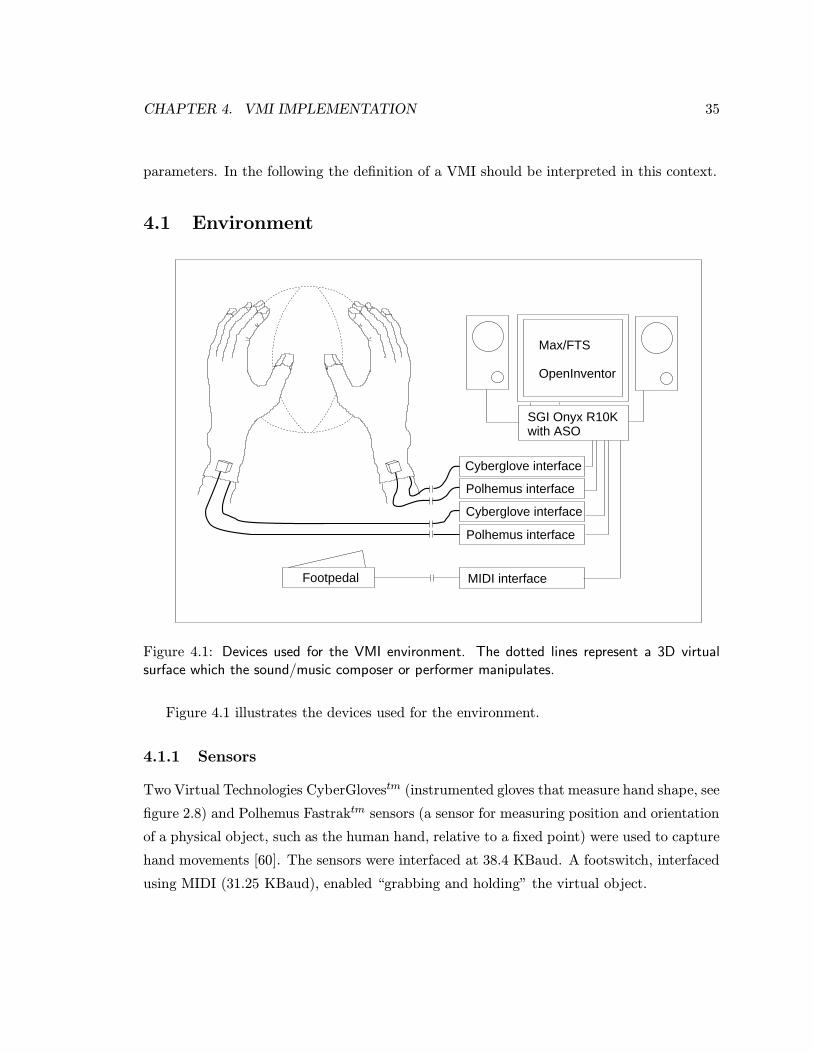
CHAPTER 4. VMI IMPLEMENTATION 35
parameters. In the following the definition of a VMI should be interpreted in this context.
4.1 Environment
Cyberglove interface
Cyberglove interface
Polhemus interface
Polhemus interface
SGI Onyx R10K with ASO
Max/FTS
OpenInventor
MIDI interfaceFootpedal
Figure 4.1: Devices used for the VMI environment. The dotted lines represent a 3D virtualsurface which the sound/music composer or performer manipulates.
Figure 4.1 illustrates the devices used for the environment.
4.1.1 Sensors
Two Virtual Technologies CyberGlovestm (instrumented gloves that measure hand shape, see
figure 2.8) and Polhemus Fastraktm sensors (a sensor for measuring position and orientation
of a physical object, such as the human hand, relative to a fixed point) were used to capture
hand movements [60]. The sensors were interfaced at 38.4 KBaud. A footswitch, interfaced
using MIDI (31.25 KBaud), enabled “grabbing and holding” the virtual object.
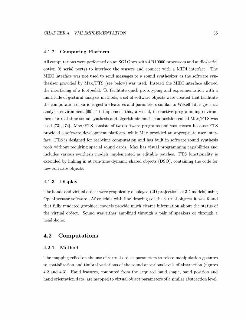
CHAPTER 4. VMI IMPLEMENTATION 36
4.1.2 Computing Platform
All computations were performed on an SGI Onyx with 4 R10000 processors and audio/serial
option (6 serial ports) to interface the sensors and connect with a MIDI interface. The
MIDI interface was not used to send messages to a sound synthesizer as the software syn-
thesizer provided by Max/FTS (see below) was used. Instead the MIDI interface allowed
the interfacing of a footpedal. To facilitate quick prototyping and experimentation with a
multitude of gestural analysis methods, a set of software objects were created that facilitate
the computation of various gesture features and parameters similar to Wexelblatt’s gestural
analysis environment [99]. To implement this, a visual, interactive programming environ-
ment for real-time sound synthesis and algorithmic music composition called Max/FTS was
used [73], [74]. Max/FTS consists of two software programs and was chosen because FTS
provided a software development platform, while Max provided an appropriate user inter-
face. FTS is designed for real-time computation and has built in software sound synthesis
tools without requiring special sound cards. Max has visual programming capabilities and
includes various synthesis models implemented as editable patches. FTS functionality is
extended by linking in at run-time dynamic shared objects (DSO), containing the code for
new software objects.
4.1.3 Display
The hands and virtual object were graphically displayed (2D projections of 3D models) using
OpenInventor software. After trials with line drawings of the virtual objects it was found
that fully rendered graphical models provide much clearer information about the status of
the virtual object. Sound was either amplified through a pair of speakers or through a
headphone.
4.2 Computations
4.2.1 Method
The mapping relied on the use of virtual object parameters to relate manipulation gestures
to spatialization and timbral variations of the sound at various levels of abstraction (figures
4.2 and 4.3). Hand features, computed from the acquired hand shape, hand position and
hand orientation data, are mapped to virtual object parameters of a similar abstraction level.
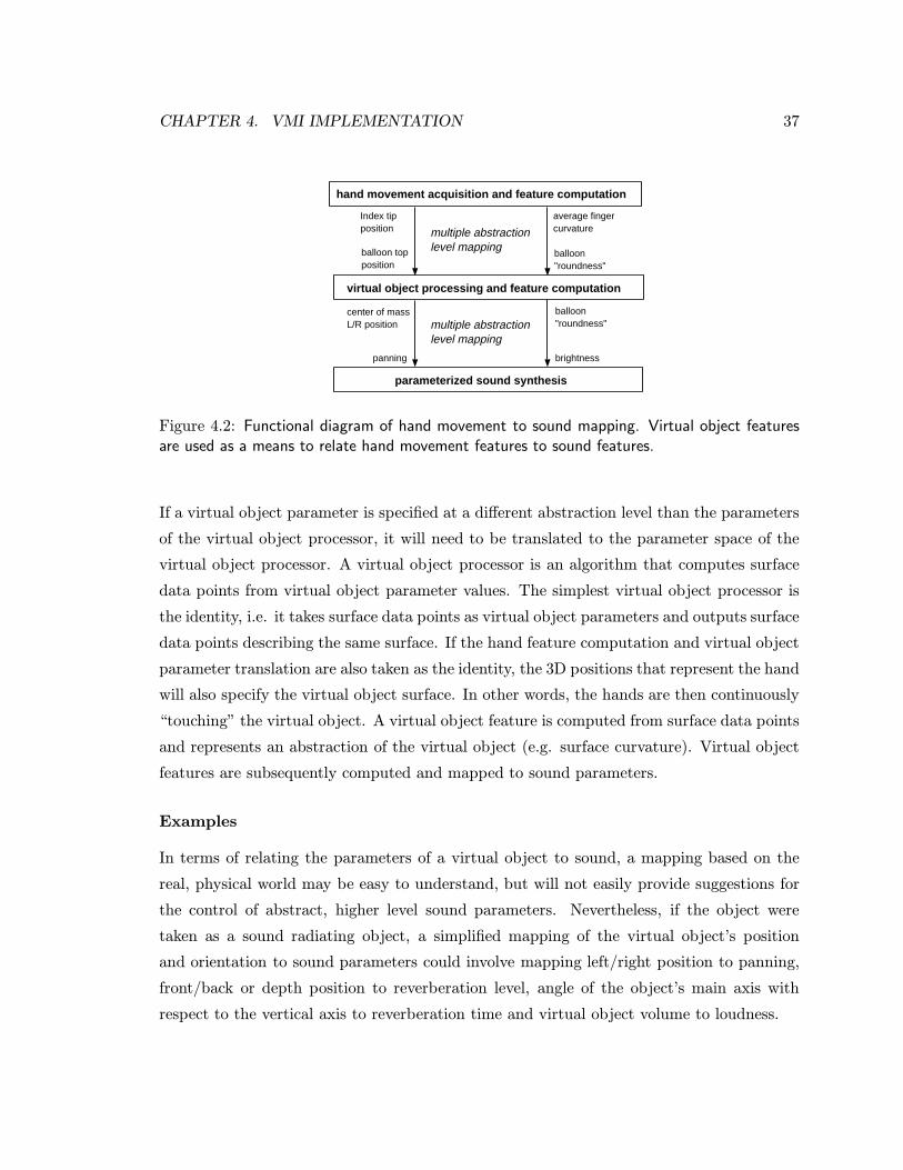
CHAPTER 4. VMI IMPLEMENTATION 37
multiple abstraction level mapping
multiple abstraction level mapping
virtual object processing and feature computation
hand movement acquisition and feature computation
parameterized sound synthesis
Index tip position
balloon top position
average finger curvature
balloon "roundness"
center of massL/R position
panning
balloon "roundness"
brightness
Figure 4.2: Functional diagram of hand movement to sound mapping. Virtual object featuresare used as a means to relate hand movement features to sound features.
If a virtual object parameter is specified at a different abstraction level than the parameters
of the virtual object processor, it will need to be translated to the parameter space of the
virtual object processor. A virtual object processor is an algorithm that computes surface
data points from virtual object parameter values. The simplest virtual object processor is
the identity, i.e. it takes surface data points as virtual object parameters and outputs surface
data points describing the same surface. If the hand feature computation and virtual object
parameter translation are also taken as the identity, the 3D positions that represent the hand
will also specify the virtual object surface. In other words, the hands are then continuously
“touching” the virtual object. A virtual object feature is computed from surface data points
and represents an abstraction of the virtual object (e.g. surface curvature). Virtual object
features are subsequently computed and mapped to sound parameters.
Examples
In terms of relating the parameters of a virtual object to sound, a mapping based on the
real, physical world may be easy to understand, but will not easily provide suggestions for
the control of abstract, higher level sound parameters. Nevertheless, if the object were
taken as a sound radiating object, a simplified mapping of the virtual object’s position
and orientation to sound parameters could involve mapping left/right position to panning,
front/back or depth position to reverberation level, angle of the object’s main axis with
respect to the vertical axis to reverberation time and virtual object volume to loudness.
CHAPTER 4. VMI IMPLEMENTATION 38
device data bytes
cyberglove and polhemus sensor values
hand limb position data
map to virtual object, e.g. average finger curvature to "roundness"
serial port bytes
character device driver
serial port
sensor protocol handler
hand geometry computation
hand feature computation
sensor input
(a) Functional diagram ofhand movement acquisitionand feature computation.
map from hand movement,e.g. average finger curvatureto "roundness"
surface data points
map to sound, e.g. "roundness"to brightness
spline control points
virtual object parameter translator
virtual object processor
virtual object feature computer
(b) Functional diagram of vir-tual object processing and fea-ture computation.
map from virtual objecte.g "roundness" to brightness
[sound sample]
sound sample data
filter settings
sound parameter translator
sound processor
D/A converter
audio out
(c) Functional diagram ofsound synthesis.
Figure 4.3: The diagrams show mapping at the feature abstraction level, but mapping at otherlevels is equally possible.
Mapping virtual object shape parameters to timbral parameters is less easily based on
the physical world, but could involve mapping the length of the main, i.e. longest, axis to
flange amplitude, transverse surface area or object width to chorus depth and curvature or
“roundness” to brightness as defined by Wessel [98].
4.2.2 Implementation
The strong data type checking of Max/FTS was used to introduce new data types such as
position and orientation for geometric and kinematic computations as well as a voxel and
hand data type. This way the user is made aware of different abstraction levels or methods
of representation which do not necessarily map linearly but may require more complicated
functionality.
Based on the mapping method and the new data types, a number of Max/FTS software
objects were programmed enabling quick and easy prototyping of various gestural analysis
computations and allowing for application of the computations to different body parts. They
are listed below with reference to figures 4.2 and 4.3. See the Max/FTS object reference
appendix for a more detailed description.
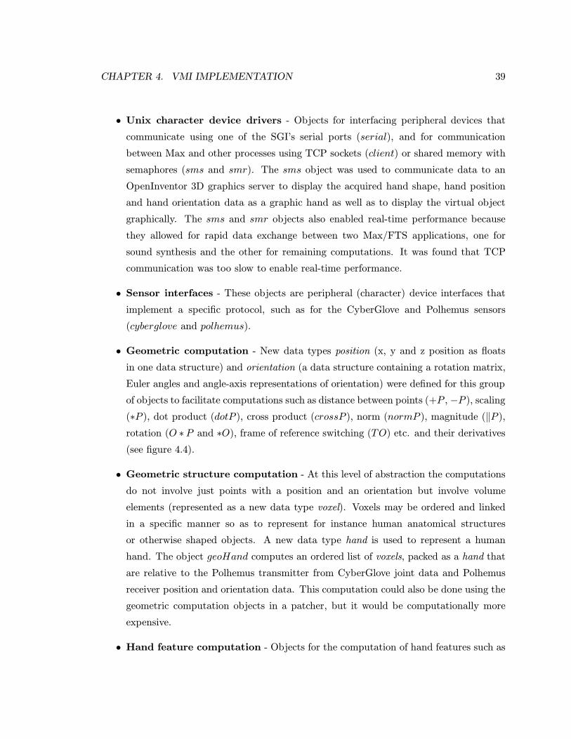
CHAPTER 4. VMI IMPLEMENTATION 39
• Unix character device drivers - Objects for interfacing peripheral devices that
communicate using one of the SGI’s serial ports (serial), and for communication
between Max and other processes using TCP sockets (client) or shared memory with
semaphores (sms and smr). The sms object was used to communicate data to an
OpenInventor 3D graphics server to display the acquired hand shape, hand position
and hand orientation data as a graphic hand as well as to display the virtual object
graphically. The sms and smr objects also enabled real-time performance because
they allowed for rapid data exchange between two Max/FTS applications, one for
sound synthesis and the other for remaining computations. It was found that TCP
communication was too slow to enable real-time performance.
• Sensor interfaces - These objects are peripheral (character) device interfaces that
implement a specific protocol, such as for the CyberGlove and Polhemus sensors
(cyberglove and polhemus).
• Geometric computation - New data types position (x, y and z position as floats
in one data structure) and orientation (a data structure containing a rotation matrix,
Euler angles and angle-axis representations of orientation) were defined for this group
of objects to facilitate computations such as distance between points (+P , −P ), scaling
(∗P ), dot product (dotP ), cross product (crossP ), norm (normP ), magnitude (‖P ),
rotation (O ∗P and ∗O), frame of reference switching (TO) etc. and their derivatives
(see figure 4.4).
• Geometric structure computation - At this level of abstraction the computations
do not involve just points with a position and an orientation but involve volume
elements (represented as a new data type voxel). Voxels may be ordered and linked
in a specific manner so as to represent for instance human anatomical structures
or otherwise shaped objects. A new data type hand is used to represent a human
hand. The object geoHand computes an ordered list of voxels, packed as a hand that
are relative to the Polhemus transmitter from CyberGlove joint data and Polhemus
receiver position and orientation data. This computation could also be done using the
geometric computation objects in a patcher, but it would be computationally more
expensive.
• Hand feature computation - Objects for the computation of hand features such as
CHAPTER 4. VMI IMPLEMENTATION 40
Figure 4.4: Typical example of geometric computing using the new Max/FTS position andorientation objects. This Max patcher takes a list of positions, projects these on the planethat best fits them, then rotates the plane (with projected positions) and eliminates z. Thispatcher enables subsequent fitting of 2D parametric curves to the x-y coordinates (e.g. the x-ycoordinates computed from the positions marking the thumb and index fingers).
the distance between thumb and index fingertips and the distance between left and
right hand palm are easily calculated using the above geometric computation objects
in a patcher. Objects were also made for computation of the orientation of a plane
(plane, see figure 4.4) such as the palm, the average position of a selected number
of points of the hand (avgP ) and for computation of features based on the path of
a selected point of the hand (bufP ). Other objects for the computation of features
such as finger and hand curvature using a curve fitting algorithm, estimated grip force
using a grasping taxonomy etc. would be useful but have not been programmed.
• Virtual object processing - The sheet object implements a physical model of a
sheet of two layers of masses connected through springs (see figure 4.5 and 4.6) [23].

CHAPTER 4. VMI IMPLEMENTATION 41
The four corners of the sheet act as the control points and can be stuck, or clamped
to the index and thumb tips of both hands for example. Similarly, balloon implements
a physical model of a single layer of masses positioned in sphere-like form (see figure
4.7 and 4.8).
• Virtual object feature computation - Many of the geometric computation objects
and some of the hand feature objects can be used to compute virtual object features.
Other types of virtual object feature computations involve superquadrics, a mathe-
matical method to describe a wide variety of shapes with two parameters specifically
related to virtual object (vertical and horizontal “roundness” or “squareness”) and
9 others for size, orientation and position of the virtual object. “Roundness” is an
abstract feature which might map well to abstract sound features such as “brightness”
[98]. Based on [87] a superquadric object was programmed that fits a virtual object
described in terms of superquadric parameters to a set of positions. As the fitting
process is iterative, it is computationally expensive (order of 100 ms). A simpler ap-
proach was implemented in a feature computation object ellipsoid which fits only a
virtual object described in terms of ellipsoid parameters (i.e. three size parameters) to
the list of positions. For 2D curve fitting the polynomial object, which approximates
a list of positions by a polynomial of at most second degree, was programmed. The
kappa2D object computes the curvature of a 2D curve, whereas the kappa3D object
computes the curvature of a 3D surface.
4.3 VMI Prototypes
Two types of VMI prototypes were created, one using a virtual object with a behaviour of
a rubber sheet and another using a virtual object with a behaviour of a rubber balloon (see
the appendix on Operating Instructions for pictures of the Max/FTS patches which were
used).
Chronologically, an attempt was first made to implement the balloon, but then found
too slow, so that the simpler model of the sheet was implemented. It was then reasoned
that by computing hand curvature from the average bending of the hand instead of fitting
a superquadric to the shape of the hands, the balloon model could still be implemented as
the computation and display of a superquadric requires far less computing time than the
fitting computations.
CHAPTER 4. VMI IMPLEMENTATION 42
The manipulation gestures for sculpting were based on the pragmatics of claying. The
virtual object could be manipulated either while it was “held” by (a selected number of)
joints and subsequent hand motions moving or changing the shape of the object or it could
be manipulated by “touching” it. A footswitch enabled selection of either manipulation
method.
To control parameters of the sound that define the spatial properties of the space in
which the sound is generated, position and orientation of the virtual objects were mapped
as if the virtual object was a sound radiating object. Thus, the virtual object’s position
and orientation were simply mapped as follows: left/right position to panning, front/back
or depth position to reverberation level, angle of the object’s main axis with respect to the
vertical axis to reverberation time and virtual object volume was mapped to loudness.
Mapping virtual object height to pitch could be “intuitive”. However, due to human
inaccuracy in moving the hands to absolute positions without tactile or force feedback
and only (delayed) acoustic and visual feedback, in combination with a high sensitivity for
perceiving pitch changes, controlling pitch in this way was ineffective. Thus, the pitch of
the sound was either fixed at one frequency, or was pre-programmed as a sequence. Instead
the virtual object height was mapped to mid-pass filter amplitude.
The remaining available sound parameters in the synthesis model used were timbral
parameters attack time, release time, flange index, chorus depth, frequency modulation
index, and low/mid/high-pass filter amplitude and filter frequency.
The virtual objects were displayed graphically in real-time as 3D projections on a 2D
screen, against a black background, together with line drawings of the hands.
4.3.1 Rubber Sheet
To implement a virtual object with a behaviour of a rubber sheet, the object sheet was used
to compute the virtual object voxels. The object holding pragmatics involved a pinch grip.
The voxels of the tips of the index and thumb fingers were used as the voxels of the four
corners of the virtual sheet. Thus, rotating, but not moving, the finger tips would result in
bending of the virtual sheet. Stretching, widening, positioning and orienting the sheet was
a direct consequence of moving the index and thumb fingers and/or the hands.
The fingertips of both hands or one hand only could be clamped to the corners of the
sheet (figure 4.5). If only one or none of the hands was clamped, the other hand or both
hands could manipulate the sheet by “touching” it (figure 4.6). Manipulation with the
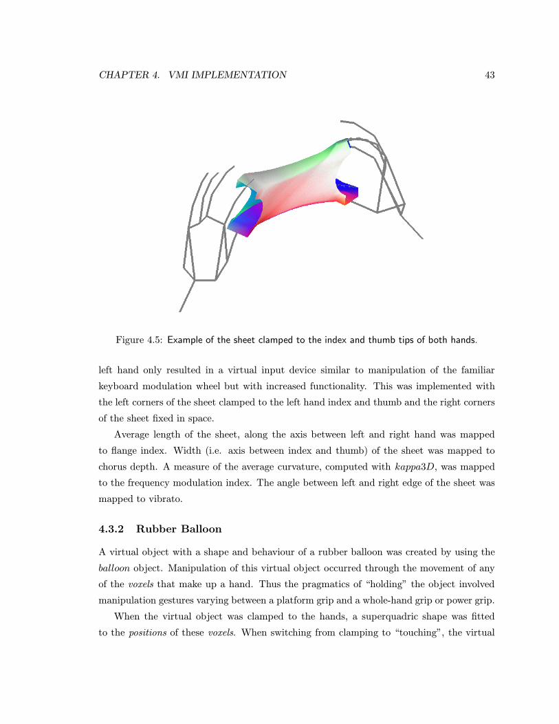
CHAPTER 4. VMI IMPLEMENTATION 43
Figure 4.5: Example of the sheet clamped to the index and thumb tips of both hands.
left hand only resulted in a virtual input device similar to manipulation of the familiar
keyboard modulation wheel but with increased functionality. This was implemented with
the left corners of the sheet clamped to the left hand index and thumb and the right corners
of the sheet fixed in space.
Average length of the sheet, along the axis between left and right hand was mapped
to flange index. Width (i.e. axis between index and thumb) of the sheet was mapped to
chorus depth. A measure of the average curvature, computed with kappa3D, was mapped
to the frequency modulation index. The angle between left and right edge of the sheet was
mapped to vibrato.
4.3.2 Rubber Balloon
A virtual object with a shape and behaviour of a rubber balloon was created by using the
balloon object. Manipulation of this virtual object occurred through the movement of any
of the voxels that make up a hand. Thus the pragmatics of “holding” the object involved
manipulation gestures varying between a platform grip and a whole-hand grip or power grip.
When the virtual object was clamped to the hands, a superquadric shape was fitted
to the positions of these voxels. When switching from clamping to “touching”, the virtual
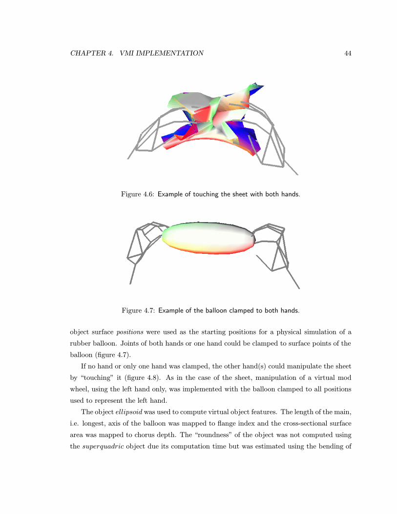
CHAPTER 4. VMI IMPLEMENTATION 44
Figure 4.6: Example of touching the sheet with both hands.
Figure 4.7: Example of the balloon clamped to both hands.
object surface positions were used as the starting positions for a physical simulation of a
rubber balloon. Joints of both hands or one hand could be clamped to surface points of the
balloon (figure 4.7).
If no hand or only one hand was clamped, the other hand(s) could manipulate the sheet
by “touching” it (figure 4.8). As in the case of the sheet, manipulation of a virtual mod
wheel, using the left hand only, was implemented with the balloon clamped to all positions
used to represent the left hand.
The object ellipsoid was used to compute virtual object features. The length of the main,
i.e. longest, axis of the balloon was mapped to flange index and the cross-sectional surface
area was mapped to chorus depth. The “roundness” of the object was not computed using
the superquadric object due its computation time but was estimated using the bending of
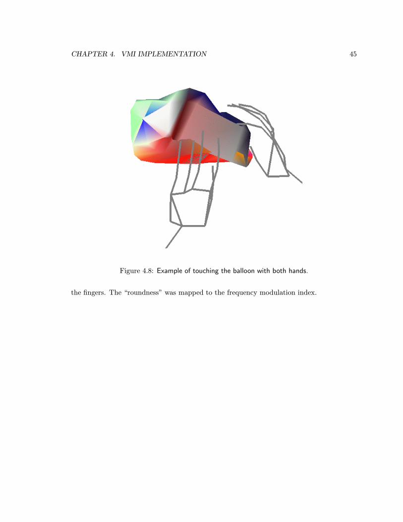
CHAPTER 4. VMI IMPLEMENTATION 45
Figure 4.8: Example of touching the balloon with both hands.
the fingers. The “roundness” was mapped to the frequency modulation index.
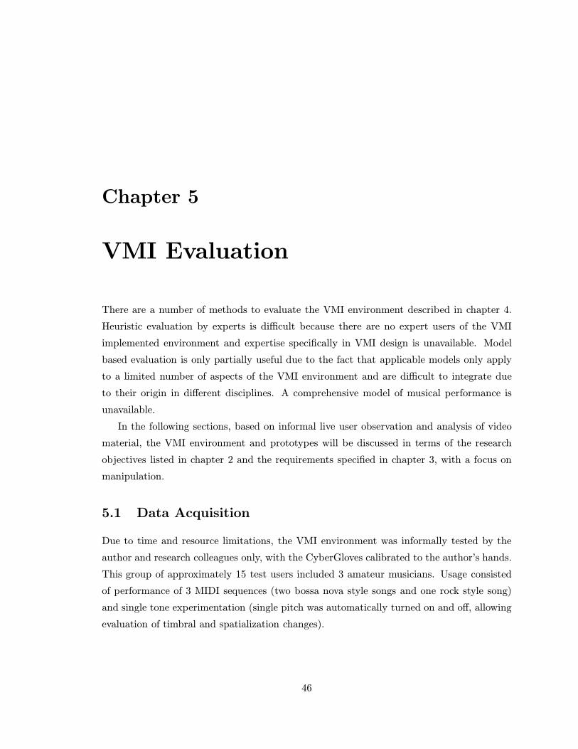
Chapter 5
VMI Evaluation
There are a number of methods to evaluate the VMI environment described in chapter 4.
Heuristic evaluation by experts is difficult because there are no expert users of the VMI
implemented environment and expertise specifically in VMI design is unavailable. Model
based evaluation is only partially useful due to the fact that applicable models only apply
to a limited number of aspects of the VMI environment and are difficult to integrate due
to their origin in different disciplines. A comprehensive model of musical performance is
unavailable.
In the following sections, based on informal live user observation and analysis of video
material, the VMI environment and prototypes will be discussed in terms of the research
objectives listed in chapter 2 and the requirements specified in chapter 3, with a focus on
manipulation.
5.1 Data Acquisition
Due to time and resource limitations, the VMI environment was informally tested by the
author and research colleagues only, with the CyberGloves calibrated to the author’s hands.
This group of approximately 15 test users included 3 amateur musicians. Usage consisted
of performance of 3 MIDI sequences (two bossa nova style songs and one rock style song)
and single tone experimentation (single pitch was automatically turned on and off, allowing
evaluation of timbral and spatialization changes).
46

CHAPTER 5. VMI EVALUATION 47
Documentation
Some of the use of the environment by the author was videotaped:
• 2-handed balloon performance (29 min)
• 1-handed balloon performance (4 min)
• 2-handed sheet performance (14 min)
• 1-handed sheet performance (8 min)
The appendix includes an edited version of this video material together with a description
of the system.
5.2 Manipulation
The design goal was to allow the performer to interact with the control surface using common
manipulation pragmatics. Moving and rotating the virtual object while “holding” it was
mostly effortless, as it was virtually identical to the manipulation of physical objects.
Touching the virtual object to move, rotate or shape the virtual object, required effective
feedback of the contact between the hands and the virtual object. As no tactile feedback or
force feedback was available, the performer had to rely on the visual feedback generated from
the hand movements affecting the virtual object or the performer had to rely on changes
in the sound. This method proved not so effective, probably because of a lack of suitable
depth cues and because the absolute location of the virtual object had to be kinesthetically
remembered (instead of being able to rely on tactile feedback when collision of the hand with
object occurred) each time the hands moved without affecting the virtual object surface.
Most test subjects informally felt more comfortable working with the balloon than with
the sheet given the sonifications used. Further testing is needed to verify whether this
preference was due to the sonification of balloon features or to the type of manipulation the
balloon afforded. Differences between the two prototypes are outlined below.
5.2.1 Rubber Sheet
The control of virtual object position and orientation took no time to get used to as it
was similar to manipulation of physical objects. As for shape, it was found that control of
CHAPTER 5. VMI EVALUATION 48
curvature was limited by the fact that only the four corners of the sheet could be manipulated
using the pinch grip. Normally, one positions fingers or fingertips in various ways on the
surface to control the curvature. For example, to create a curved sheet, movements had
to be exaggerated. Also, it was not possible to create a sheet with double bending in
one direction. This limitation resulted sometimes in unwanted co-articulation of shape
parameters, i.e. it was difficult to accept the limited control of curvature and not affect
other shape features with the exaggerated movements. Some co-articulation of shape and
position and/or orientation features was unavoidable, but could, with careful attention, be
kept to a minimum. The length was easiest to control, then the width and the angle between
left and right edge of the sheet.
Using the sheet as a virtual modulation wheel allowed left hand gestures to be more
expressive than typical keyboard modulation wheel gestures and hence provided for a more
dramatic performance effect. In addition, the reference point (the right corners) could easily
be moved, so as to accommodate rapid changes in the zero-point of any modulations given
different musical context, by clamping the right corners to the right hand temporarily.
5.2.2 Rubber Balloon
The “holding” of the virtual object was somewhat unnatural, as parts of the hand sometimes
passed through the surface of the virtual object during manipulations.
It was unclear how to infer “roundness” of the virtual object accurately from the per-
former’s movements, due to the fact that normally the hand is only partially touching an
object’s surface. Any sphere-like object can be held with anywhere from a few finger tips to
the entire hand to change the shape using claying pragmatics. This problem made “round-
ness” difficult to control and resulted, as in the case of the sheet, in unwanted co-articulation
of shape parameters. When the cross-sectional surface area was increased the balloon would
also become more rectangular or ellipsoid if the performer would unintentionally extend or
flex the fingers. In addition, due to errors in the estimation of finger bending sometimes jit-
ter occurred, i.e. the virtual object would at times jump from cube-like to ellipsoid without
any significant hand motions. As with the sheet, some co-articulation of shape and position
and/or orientation features was unavoidable, but could, with careful attention, be kept to
a minimum.
Manipulation using the left hand only, with the balloon entirely clamped to the hand
was not as natural as in the case of the sheet, most likely due to a missing reference point
CHAPTER 5. VMI EVALUATION 49
(the rightmost corners in the case of the sheet - in hindsight, the balloon could also have
been fixed in space at one end) and hence more difficulty in manipulating the shape of the
balloon with one hand. Nevertheless manipulation of the position and orientation of the
virtual object was effective, but the same sound effects might have been achieved without
the presence of the virtual object. In terms of shape manipulations, balloon length was
easiest to control, then cross sectional surface area and then “roundness”.
5.3 Sonification
The design goal was to create a sonification of the control surface that is responsive (i.e.
results in perceptible changes of sound and music parameters) to performer gestures. This
was not an easy task. For example, it was found that when mapping a virtual object feature
to a sound parameter, offsetting and scaling the value of the virtual object feature required
some arbitrary heuristics based on workspace dimensions etc. A solution without such
heuristics would be preferred. In addition, undesired co-articulation of shape parameters
required that virtual object features were chosen carefully for sonification. Due to the
available manipulation methods certain virtual object features could only be controlled
together, so they should not be mapped to sound parameters that may need to be controlled
independently. However, the main challenge was to create a sonification that had similar
expressive qualities as the gestures themselves, so that control would appear natural.
As mentioned in section 5.1, most test subjects informally felt more comfortable working
with the balloon than with the sheet given the sonifications used. Both for the rubber sheet
and for the balloon the mapping of virtual object position and orientation worked equally
well and cost no effort to learn. Informal evaluation showed the mapping of virtual object
shape to work sufficiently well. In the case of the balloon, due to jitter (i.e. the virtual
object would at times jump from cube-like to ellipsoid without any significant hand motions),
occasionally unpredictable sound variations occurred. Possibly this can be circumvented by
algorithm and patch adaptations.
5.4 Visualization
The appearance and behaviour of the control surface was sufficiently similar to common
physical objects to allow performers to immediately use the VMIs. It was not so easy to
CHAPTER 5. VMI EVALUATION 50
perceive the depth of the graphical environment and the absolute position of the virtual
object, necessary for “touching” manipulations. The lighting and coloring were effective,
and helped in cases when the surface folded through itself or turned partially inside out.
5.5 Adaptation
The design goal was to allow as many VMI aspects as possible to be adaptable and/or adap-
tive through an easy-to-use programming interface. The use of Max/FTS proved effective
for this purpose, although the version of Max/FTS used in the VMI environment suffered
from a poorly designed graphical interface. For example, the making of patches was often
tedious due to difficulty in connecting objects to other objects via “wires”and an increas-
ing difficulty in comprehending a patch the higher the number of “wires”. The ease-of-use
could definitely have been better. A new version of Max/FTS called jMax may improve this
aspect.
The addition of FTS objects allowed for quick prototyping of gestural analysis compu-
tations, and an almost unlimited number of possibilities for adaptation. Small adjustments
could easily be implemented, even while a performer was using the environment. In terms
of adaptability, the library of FTS objects was not tested for its usefulness for making VMIs
relying on sign-like languages.
5.6 Engineering
For musical performance, the VMI has to operate within real-time, i.e. hand actions have
to correspond with visual and auditory changes without any perceptible time delays. Only
if the task is to design a sound or compose music, instead of performing it, auditory changes
may be delayed, but visual changes should still be occurring in real-time. The main de-
lays were incurred by the sensor data acquisition (approximately 60 ms) and the physical
modeling computations (approximately 8 ms).
The sensor data acquisition delay could not be reduced to the theoretically possible
minimum. Probably the long serial cables (approximately 30 m) connecting the computer
in one room with the serial interfaces in another room prohibited use of higher baudrates
(56K and 115K). The computations could be completed in real-time if a suitably low (order
of 100) number of virtual masses of the physical models was chosen. The computation of
CHAPTER 5. VMI EVALUATION 51
sound synthesis parameters and sound generation occurred in approximately 2 ms, so that
acoustic feedback occured within approximately 70 ms, which is very close to real-time (60
ms) given the type of sound changes. The OpenInventor software displayed the graphics
within three frames (i.e. 50 ms on a 60 Hz refresh rate monitor), so that the visualization
was displayed within at most 120 ms, i.e. within real-time (200 ms).
The combination of CyberGlove and Polhemus sensors captured almost all possible hand
movements and gestures. While the CyberGlove is probably one of the most accurate means
to register human hand movements, accurate measurement of thumb movement was still
difficult due to the fact that the sensors intended for the thumb did not map to single
joints but to some of the neighbouring joints at the same time. Nevertheless, with the hand
model used it was possible to reach acceptable accuracy for the purpose of this research,
but the calibration was somewhat tedious as well as individual specific. Each joint had
to be separately calibrated by setting the gain and offset of each joint flex sensor. No
patch was implemented that allowed a user to execute a standard set of postures and/or
gestures to provide calibration settings. Last but not least, the tethering of the sensors was
inconvenient.
At the beginning of this research a graphical display was not deemed a high priority,
but during development the graphical display of hands and virtual object proved to be very
useful as a method to verify that hand and shape modeling were operating correctly and it
also proved a simple way to show new users what to do. Its likely that even with experienced
users the graphical display will have some value to finetune their motions.
5.7 Summary
Based on informal testing by the author, a handful or research colleagues and video material
of the author’s use of the environment, the evaluation of the VMI environment can be
summarized as follows:
• Manipulation - The control of virtual object shape often required some effort to
master due to the need for exaggerated movements and/or the need to learn limitations
to the control of shape. Due to these limitations to manipulation, unwanted co-
articulation of virtual object features could occur. While it is possible that such
co-articulation can be used to the performers advantage in certain tasks, in the real
world the virtual object features used can be controlled separately. The “touching”
CHAPTER 5. VMI EVALUATION 52
of virtual objects was difficult due to a lack of tactile and force feedback, or suitable
depth clues.
• Sonification - The mapping of position and orientation to spatialization parameters
proved easy to use. The mapping of virtual object shape to a variety of timbral pa-
rameters offered no obvious analogy to the physical world to the user. Thus, learning
was required to obtain desired acoustic feedback in a natural way using the manipu-
lation methods. Forced co-articulation of some shape features prohibited independent
control of the sound parameters they were mapped to. Scaling and offsetting of virtual
object features for mapping to sound parameters was somewhat arbitrary.
• Adaptation - Although adaptation of VMIs was possible in many diverse ways, the
user interface to implement these adaptations was not so easy to use without significant
technical expertise.
• Engineering - While acceptable real-time performance capturing almost all hand
gestures, was achieved, expensive technology is required to implement it.
• Interaction - Different types of interaction were tried out. The left-hand-only ma-
nipulation method could provide a useful alternative to the standard keyboard mod-
ulation wheel in situations where the right hand is needed for pitch control using e.g.
a keyboard. The naturalness of the interaction is affected by both the manipulation
methods afforded by the virtual object and the sonification of the object and appears
natural if inspired by the physical world.
5.8 Recommendations
Based on the experience with the implemented VMI environment the following recommen-
dations and ideas can be listed for continuation and extension of the work:
• Pragmatics - There is a need to identify and address manipulation pragmatics in
more detail, which should make manipulation of the virtual musical instrument easier
because it will make a better use of already established movement patterns, while in
some cases undesirable co-articulation of virtual object features may be avoided.
CHAPTER 5. VMI EVALUATION 53
• Manipulation vs. Signing - The distance between the virtual object and the per-
former’s hand(s) can perhaps be used to interpret hand movements that occur far
from an object in terms of symbols, i.e. as gesticulation and/or signing (depend-
ing on the formalization), while hand movements in close proximity to an object can
be interpreted as multidimensional continuous parameter changes, i.e. manipulation
gestures.
• Touch/Force - Touch and force feedback will make the control of timing aspects
of musical performance available, and also enable finer control of the virtual musical
instrument.
• Simulation - To improve the behaviour of the virtual object in response to the manip-
ulation by the performer more accurate and detailed (physical) models of 3D surfaces
are needed.
• Motion - Virtual objects may have mass and hence gain momentum from manipula-
tions, making autonomous motions or shape changes.
• Fuzzy Boundary - Force fields or fuzzy boundaries surrounding an object can be
programmed to enable multiple objects to affect each other. Useful when different
objects have intersecting motion paths.
• Zones - Spatial zones can be defined that alter the sound (e.g. sound effects are
applied) when the object is placed in or moved through it.
• Sonification - A significant amount of work needs to be done to identify suitable
methods to visualize sound in terms of features of a 3D virtual object. In addition,
co-articulated virtual object features, whether desired or not, should be sonified such
that they do not force the user to make unusual movements.
• Real-time - The speed of sensor data acquisition needs to increase while computa-
tional efficiency needs to improve in order to enable higher detail and tighter control
of the sound parameters.
• Wireless - Wireless connections will make the CyberGlove and Polhemus sensors
much easier to use.

CHAPTER 5. VMI EVALUATION 54
• Display - For a better perception of the absolute position of the virtual object, useful
for more accurate “touching” manipulations, a patterned background with depth clues
as well as a 3D display may be helpful.
• Multi-object - An expansion of the environment where multiple virtual musical in-
struments, each representing an auditory stream such as notes and/or speech, can be
accessed and controlled will enable a conductor and orchestra performance configura-
tion.
• Multi-user - The environment can be expanded to a configuration where multiple
(remotely networked) performers control each their own virtual musical instrument or
together one virtual musical instrument.
• Other Domains - The developed interaction methodology may be applied to other
domains, such as the editing of texture, color and lighting of graphical objects.
Chapter 6
Conclusion
What can be learned from the musical instrument design experiment involving advanced
human movement tracking technology described in this dissertation ?
The main result of the research is that a prototype of an environment for design of virtual
instruments with 3D geometry has been successfully implemented, allowing real-time perfor-
mance in 3D and adaptation to exploit many manipulation gestures.
While this result is encouraging, the preliminary evaluation of the environment showed that
for a natural interaction to take place the user or performer should be able to:
• 1. apply manipulation methods used in everyday life to change shape, position and
orientation of the virtual object
• 2. believe that the sonification of the virtual object is qualitatively and directly related
to the variations in virtual object shape position and orientation.
Contribution in Context
If we examine the results in the context of the discussion in chapter 2, the contribution of this
research appears tiny, as the implemented VMI prototypes appear such rudimentary musical
instruments, unable to withstand any comparison with traditional, real acoustic instruments.
While adaptation is virtually unlimited within the VMI environment, such adaptations still
require a significant amount of technical expertise. Nevertheless, in comparison, similar
adaptations of physical instruments not only require an equal or greater amount of technical
55
CHAPTER 6. CONCLUSION 56
expertise but are also limited by the laws of physics. On the other hand, physical instruments
offer the musically very useful tactile and (usually) force feedback.
In terms of human factors and gestural communication research, the work has shown
the feasibility and usefulness of 3D interactive virtual input devices in a sound control
task - further work is needed to demonstrate usefulness in other application domains. The
value of the VMI environment as a virtual input device prototyping tool should not be
underestimated. More on the theoretical side, different forms of sculpting pragmatics were
identified.
In terms of music and performing arts research, exciting new possibilities for musi-
cal performance have been identified and shown to be technically feasible (though costly).
A research and development path to realize these new performance possibilities has been
identified. The virtual modulation wheel, although much work is needed to find an appro-
priate implementation, is one of the many examples of new virtual controllers that can be
prototyped in the VMI environment. Last but not least, it would easily be overlooked that
Max/FTS, a state of the art sound and music programming environment, has been extended
with a gesture analysis library of software objects.
Future Work
Future work should address an important question that arose from this research:
To what extent do performers really want their musical instruments adapted during their
career, if they were given unlimited freedom to require such adaptation ?
This question can be answered by experimentation with a musical instrument design en-
vironment as was implemented for the research presented in this dissertation. While the
current environment focusses on hand movements, future work may also address other types
of human movement.
Furthermore, while chapter 5 includes detailed recommendations for how the current
prototype can be expanded and improved, more generally future research on VMI’s should
concentrate on the identification of manipulation pragmatics, and their derived forms which
are present in gesticulation and sign languages, as well as how movement features are co-
articulated. Equal effort should be spent on identifying methods to visualize sound in terms
of features of a 3D virtual object. While chapter 3 is a first attempt to cover some of these
issues within the context of (virtual) musical instrument design, a more comprehensive
CHAPTER 6. CONCLUSION 57
understanding of these two elements is needed. This understanding will contribute to the
creation of useful, effective and enjoyable new interaction methods. Engineering efforts
should concentrate on the implementation of virtual object simulation techniques and faster
sensor data acquisition, while whole-hand tactile and force feedback are most desirable for
realization of more refined and immediate interaction.

Appendix: Operating Instructions
The Sound Sculpting application consists of two Max/FTS applications and one OpenInventor-
based application that are all run on one multi-processor SGI machine with audio-serial
option to connect to CyberGlove, Polhemus and footpedal. In the following sections the
various components and options are explained and detailed. See the appendix “Max/FTS
object reference” for details on the added functionality to Max/FTS.
Equipment
Equipment list:
1 SGI R10K multiprocessor such as an Onyx with audio-serial option (ASO)
1 Virtual Technologies left hand CyberGlove instrumented glove with serial interface
1 Virtual Technologies right hand CyberGlove instrumented glove with serial interface
3 Polhemus Fastrak 6 DOF sensors with one serial interface
1 RS232 to RS422 converter (Roland Sound Canvas 55 mkII can be used as such)
1 MIDI foot pedal or 1 Infusion Systems I-Cube Digitizer with TapTile sensor [103]
1 MIDI keyboard
headphones or sound amplifier with speakers
MIDI cables
Software:
IRCAM Max/FTS version 1.5.3 - real-time, graphical programming language
ssView - OpenInventor-based graphics command server
58
APPENDIX: OPERATING INSTRUCTIONS 59
MIDI installation
MIDI can be operated on any of the 6 serial ports (usually tty72) of an SGI with ASO
by typing “startmidi -n midiPort1 -p aso232 -d /dev/ttyd72”. The name of the port will
be “midiPort1”, and a RS232 capable MIDI hardware interface, such as the Roland Sound
Canvas 55 mkII, or an RS232 to RS422 converter in conjunction with an RS422 based MIDI
interface should be used.
Max/FTS installation
To operate Sound Sculpting Max/FTS version 1.5.3 requires the shared objects libicube.so
and libss.so to be linked at boot time. A file named .ftsbootload should be present in the
directory /homedir and it should contain the lines:
ss /homedir/ss/fts/lib/irix6.2/libss.so
icube /homedir/ss/fts/lib/irix6.2/libicube.so
Hand Modeling and Virtual Object Processing
Max startup script “/homedir/ss/Max-hand” starts up Max/FTS with small audio buffers
and MIDI (internal and via the serial port). The patch “handControl” is automatically
opened.
Commands for hand.pat:
reset - button to initialize hand.pat (this takes about 11 seconds)
point - button to obtain one dataset from hand.pat
stream - switch to turn on/off continuous sampling from hand.pat
draw - switch to turn on/off sending out of drawing commands (make sure ssView is running
first)
Commands for sheet.pat:
inlet 0 - expects 0 or 1 from switch to turn computation of the sheet on/off
inlet 1 - expects bang from button to initialize sheet.pat
inlet 2 - expects 0 or 1 from switch to turn on/off sending out of drawing commands (ssView
APPENDIX: OPERATING INSTRUCTIONS 60
is required to display the graphics)
inlet 3 - expects 0 or 1 from switch to turn on/off clamping
inlet 4 - expects 0 or 1 from switch between holding left edge of sheet with left hand or
entire sheet with both hands
inlet 5 - expects 0 or 1 from switch between only corners or entire fixing of the sheet
inlet 6 - switch to turn on/off touching the sheet with finger tips
Commands for graphicsS.pat:
open - button to open a shared memory buffer with key 1
closeServer - message to close ssView (if it is open in the first place, shared memory buffer
with key 1 will still remain open)
Commands for balloon.pat:
inlet 0 - expects 0 or 1 from switch to turn computation of the balloon on/off
inlet 1 - expects 0 or 1 from switch to turn on/off sending out of drawing commands (ssView
is required to display the graphics)
inlet 2 - expects 0 or 1 from switch to turn on/off clamping
inlet 3 - expects 0 or 1 from switch between holding balloon with left hand or with both
hands
inlet 4 - expects 0 or 1 from switch between no fixing or entire fixing of the balloon
inlet 5 - switch to turn on/off touching the balloon with any finger joints
Commands for sheet-snd.pat:
inlet 0 - switch to turn computation and mapping of sheet features on/off
Commands for balloon-snd.pat:
inlet 0 - switch to turn computation and mapping of balloon features on/off
Commands for soundS.pat:
send - button to enable writing to shared memory buffer with key 2
Commands for note-color.pat:
APPENDIX: OPERATING INSTRUCTIONS 61
draw - switch to turn on/off mapping of incoming MIDI notes to color of graphically dis-
played surface
Sound Synthesis
Max startup script “/homedir/ss/Max-sound” starts up Max/FTS with large audio buffers
to avoid any clicks and both internal MIDI as well as serial port MIDI. The patch “sound-
Control” is automatically opened.
Commands for polySynth.pat:
trig - trigger a 10 second (duration can be set from within polySynth.pat) note from
polySynth.pat
beat - switch to turn on/off pulsed sound from polySynth.pat
intern - button to increment MIDI channel for receiving MIDI notes (channel can also be
set using the number box below it) from internal (to SGI) MIDI sources for polySynth.pat
keyb - button to increment MIDI channel for receiving MIDI notes (channel can also be set
using the number box below it) from MIDI keyboard for polySynth.pat
notes off - button to turn off receiving any MIDI notes (channel is set using the number
box beside it) from any MIDI source for polySynth.pat
slider - slider to set volume for any MIDI notes (channel is set using the number box beside
it) from any MIDI source for polySynth.pat
Commands for soundR.pat:
receive - button to enable reading of shared memory buffer with key 2
(this buffer should be opened by starting up the Max-hand application, see below/above)
Max/FTS patches for Sound Sculpting
Below follows a brief description of the Max/FTS patches used to run the sound sculpting
application. All these patches can be found in /homedir/ss/.
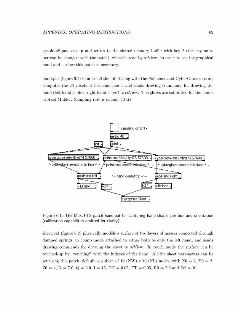
APPENDIX: OPERATING INSTRUCTIONS 62
graphicsS.pat sets up and writes to the shared memory buffer with key 2 (the key num-
ber can be changed with the patch), which is read by ssView. In order to see the graphical
hand and surface this patch is necessary.
hand.pat (figure 6.1) handles all the interfacing with the Polhemus and CyberGlove sensors,
computes the 23 voxels of the hand model and sends drawing commands for drawing the
hand (left hand is blue, right hand is red) to ssView. The gloves are calibrated for the hands
of Axel Mulder. Sampling rate is default 40 Hz.
Figure 6.1: The Max/FTS patch hand.pat for capturing hand shape, position and orientation(calibration capabilities omitted for clarity).
sheet.pat (figure 6.2) physically models a surface of two layers of masses connected through
damped springs, in clamp mode attached to either both or only the left hand, and sends
drawing commands for drawing the sheet to ssView. In touch mode the surface can be
touched-up by “touching” with the indexes of the hand. All the sheet parameters can be
set using this patch, default is a sheet of 10 (NW) x 10 (NL) nodes, with X0 = 2, Y0 = 2,
Z0 = 4, K = 7.0, Q = 3.0, I = 15, DT = 0.05, FT = 0.05, R0 = 2.0 and IM = 10.
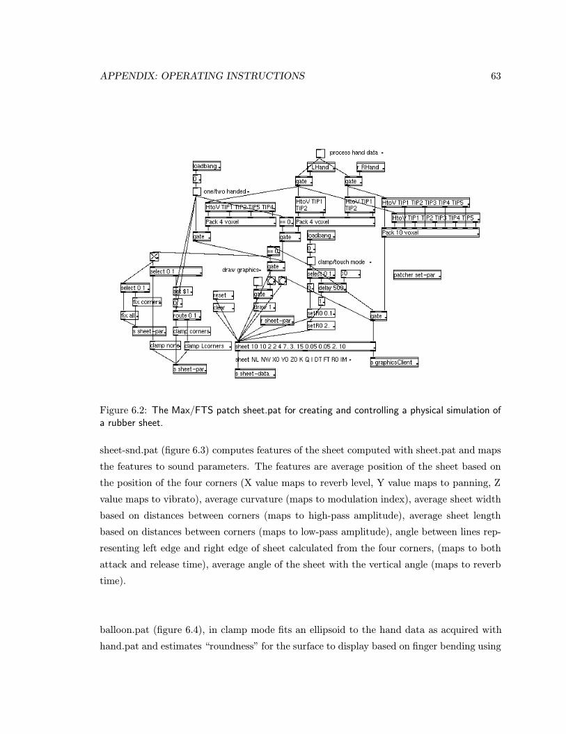
APPENDIX: OPERATING INSTRUCTIONS 63
Figure 6.2: The Max/FTS patch sheet.pat for creating and controlling a physical simulation ofa rubber sheet.
sheet-snd.pat (figure 6.3) computes features of the sheet computed with sheet.pat and maps
the features to sound parameters. The features are average position of the sheet based on
the position of the four corners (X value maps to reverb level, Y value maps to panning, Z
value maps to vibrato), average curvature (maps to modulation index), average sheet width
based on distances between corners (maps to high-pass amplitude), average sheet length
based on distances between corners (maps to low-pass amplitude), angle between lines rep-
resenting left edge and right edge of sheet calculated from the four corners, (maps to both
attack and release time), average angle of the sheet with the vertical angle (maps to reverb
time).
balloon.pat (figure 6.4), in clamp mode fits an ellipsoid to the hand data as acquired with
hand.pat and estimates “roundness” for the surface to display based on finger bending using
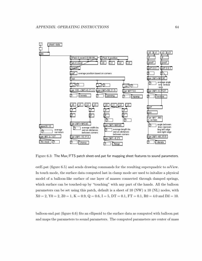
APPENDIX: OPERATING INSTRUCTIONS 64
Figure 6.3: The Max/FTS patch sheet-snd.pat for mapping sheet features to sound parameters.
estE.pat (figure 6.5) and sends drawing commands for the resulting superquadric to ssView.
In touch mode, the surface data computed last in clamp mode are used to initalize a physical
model of a balloon-like surface of one layer of masses connected through damped springs,
which surface can be touched-up by “touching” with any part of the hands. All the balloon
parameters can be set using this patch, default is a sheet of 10 (NW) x 10 (NL) nodes, with
X0 = 2, Y0 = 2, Z0 = 1, K = 0.9, Q = 0.6, I = 5, DT = 0.1, FT = 0.1, R0 = 4.0 and IM = 10.
balloon-snd.pat (figure 6.6) fits an ellipsoid to the surface data as computed with balloon.pat
and maps the parameters to sound parameters. The computed parameters are center of mass
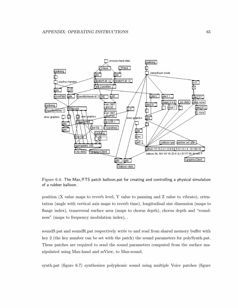
APPENDIX: OPERATING INSTRUCTIONS 65
Figure 6.4: The Max/FTS patch balloon.pat for creating and controlling a physical simulationof a rubber balloon.
position (X value maps to reverb level, Y value to panning and Z value to vibrato), orien-
tation (angle with vertical axis maps to reverb time), longitudinal size dimension (maps to
flange index), transversal surface area (maps to chorus depth), chorus depth and “round-
ness” (maps to frequency modulation index), .
soundS.pat and soundR.pat respectively write to and read from shared memory buffer with
key 2 (the key number can be set with the patch) the sound parameters for polySynth.pat.
These patches are required to send the sound parameters computed from the surface ma-
nipulated using Max-hand and ssView, to Max-sound.
synth.pat (figure 6.7) synthesizes polyphonic sound using multiple Voice patches (figure
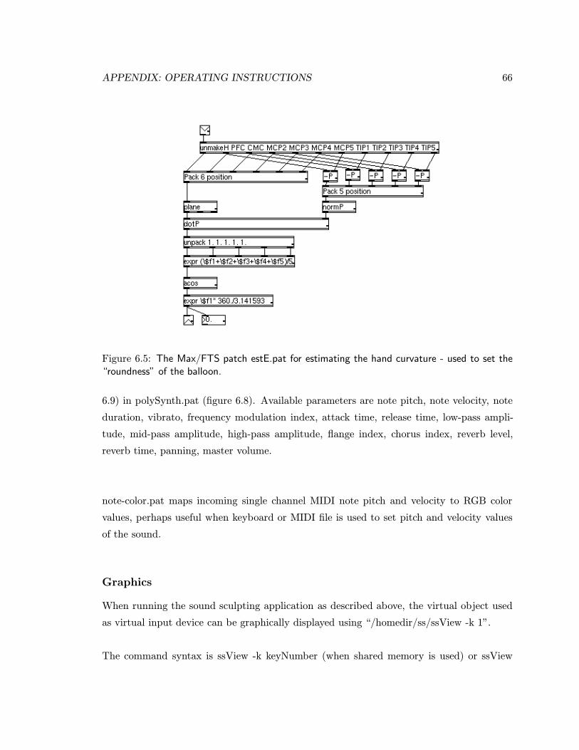
APPENDIX: OPERATING INSTRUCTIONS 66
Figure 6.5: The Max/FTS patch estE.pat for estimating the hand curvature - used to set the“roundness” of the balloon.
6.9) in polySynth.pat (figure 6.8). Available parameters are note pitch, note velocity, note
duration, vibrato, frequency modulation index, attack time, release time, low-pass ampli-
tude, mid-pass amplitude, high-pass amplitude, flange index, chorus index, reverb level,
reverb time, panning, master volume.
note-color.pat maps incoming single channel MIDI note pitch and velocity to RGB color
values, perhaps useful when keyboard or MIDI file is used to set pitch and velocity values
of the sound.
Graphics
When running the sound sculpting application as described above, the virtual object used
as virtual input device can be graphically displayed using “/homedir/ss/ssView -k 1”.
The command syntax is ssView -k keyNumber (when shared memory is used) or ssView
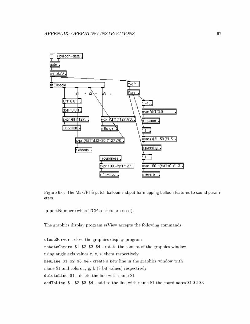
APPENDIX: OPERATING INSTRUCTIONS 67
Figure 6.6: The Max/FTS patch balloon-snd.pat for mapping balloon features to sound param-eters.
-p portNumber (when TCP sockets are used).
The graphics display program ssView accepts the following commands:
closeServer - close the graphics display program
rotateCamera $1 $2 $3 $4 - rotate the camera of the graphics window
using angle axis values x, y, z, theta respectively
newLine $1 $2 $3 $4 - create a new line in the graphics window with
name $1 and colors r, g, b (8 bit values) respectively
deleteLine $1 - delete the line with name $1
addToLine $1 $2 $3 $4 - add to the line with name $1 the coordinates $1 $2 $3

APPENDIX: OPERATING INSTRUCTIONS 68
clearLine $1 - clear the line with name $1
super2D $1 $2 $3 $4 - draw a superquadric 2D curve with e1, a1, a2 and precision $4
super2Dtrans $1 $2 $3 $4 $5 $6 $7 - transform (translate and rotate) the superquadric
2D curve using parameters x, y, z (translation) and angle axis parameters a1, a2, a3, theta
super3D $1 $2 $3 $4 - draw a superquadric 3D virtual object with e1, a1, a2 and precision
$4
super3Dtrans $1 $2 $3 $4 $5 $6 $7 - transform (translate and rotate) the superquadric
2D curve using parameters x, y, z (translation) and angle axis parameters a1, a2, a3, theta
handColor $1 $2 $3 - change the color of the hand stick figure to color r, g, b
handCoords $1 $2 ..$70 - draw a hand stick figure of the left ($1 == 1) or right ($1 ==
0) hand using the coordinates given in $2 ..$70 (coordinates of respectively CMC, MCP1,
PIP1, TIP1, MCP2, PIP2, DIP2, TIP2, MCP3, PIP3, DIP3, TIP3, MCP4, PIP4, DIP4,
TIP4, MCP5, PIP5, DIP5, TIP5, PFC, RCUC, PHR)
sheetColor $1 $2 $3 - change the color of the sheet to color r, g, b
sheetCoords $1 $2 $3 .. - draw a sheet with $1 nodes in the length direction hand $2
nodes in the width direction, given the $1 * $2 coordinates specified as triplets $3 $4 $5 etc.
Bugs: Whenever Max/FTS crashes shared memory may be left open - closing ssView will
not close the shared memory. Remove the shared memory by using “ipcs” (to see IDs of
opened shared memory and semaphores) and ipcrm -m 〈 memory ID 〉 (to remove shared
memory) and ipcrm -s 〈 semaphore ID 〉 (to remove semaphores)
The OpenInventor [97] source code for ssView can be found in /homedir/fts/dev/src/graphics/,
files userIF2.c++, hand2.c++, serverLib.c, buffer.c, superQuad.c++, superQuad3D.c++,
line.c++.
Running Sound Sculpting
Having read all of the above, you are now ready to startup sound sculpting. The procedure
for starting up is:
connect and turn on all equipment
run “Max-hand”
APPENDIX: OPERATING INSTRUCTIONS 69
initialize the Cyberglove and Polhemus sensors
run “Max-sound”
run “ssView -k 1”
now you can select various options from the two Max windows
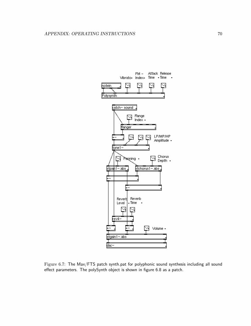
APPENDIX: OPERATING INSTRUCTIONS 70
Figure 6.7: The Max/FTS patch synth.pat for polyphonic sound synthesis including all soundeffect parameters. The polySynth object is shown in figure 6.8 as a patch.
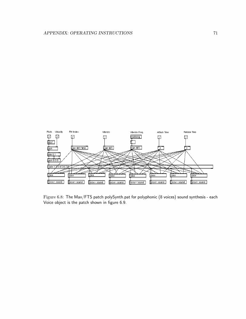
APPENDIX: OPERATING INSTRUCTIONS 71
Figure 6.8: The Max/FTS patch polySynth.pat for polyphonic (8 voices) sound synthesis - eachVoice object is the patch shown in figure 6.9.
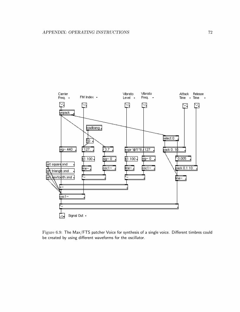
APPENDIX: OPERATING INSTRUCTIONS 72
Figure 6.9: The Max/FTS patcher Voice for synthesis of a single voice. Different timbres couldbe created by using different waveforms for the oscillator.
Appendix: Max/FTS Object
Reference
The following details the Max/FTS objects that were added to the Max/FTS environment
specifically for the purpose of sound sculpting.
Communication
sms
Send data to other applications on the same machine or to the same Max/FTS (like stan-
dard send object) using shared memory with semaphores.
Object argument: default key (integer value)
Commands:
openSmem $1 - sets up shared memory buffer with key $1
closeSmem - closes shared memory buffer opened with openSmem
lowPrec - cuts floats to only one decimal when writing in shared memory buffer
printTime - print time in ms required to write complete message in shared memory buffer
printData - show debug messages
Bugs: Whenever Max/FTS crashes shared memory may be left open. Remove the shared
memory by using “ipcs” (to see opened shared memory) and ipcrm -m 〈 memory ID 〉 (to
remove shared memory) and ipcrm -s 〈 semaphore ID 〉 (to remove semaphores)
73

APPENDIX: MAX/FTS OBJECT REFERENCE 74
Source code file: smem.c (shmemlib.c, buffer.c, ssutil.c)
smr
Receive data from other applications on the same machine or from the same Max/FTS (like
standard receive object) using shared memory with semaphores.
Object argument: default key (integer value)
Commands:
attachSmem $1 - attach to shared memory buffer with key $1
closeSmem - closes shared memory buffer opened with openSmem
printTime - print time in ms required to read complete message from shared memory buffer
and send it out the outlet
printData - show debug messages
Source code file: serial.c (shmemlib.c, buffer.c, ssutil.c)
serial
Send and receive characters via the serial port using a Unix character device driver. Note
that a message received in any of the inlets is immediately sent out, rather than usual wait-
ing for a message in the leftmost inlet.
Object argument: number of serial ports to interface (on the Onyx at most 6)
Commands:
send it out the outlet
open $1 $2 $3 - open serial device $1 at $2 baud on inlet and outlet $3 close $1 - close
device $1 printTime - print time in ms required to receive a complete message and
Source code file: serial.c (unixIO.c, ssutil.c)
APPENDIX: MAX/FTS OBJECT REFERENCE 75
client
Send and receive characters using TCP sockets using a Unix character device driver.
Object arguments: client name (e.g. “MaxClient”), machine name (e.g. “miris66”), ma-
chine port number (e.g. 2000)
Commands:
send it out the outlet
connect - connect as client name to the machine with name and port as specified in object
argument
disconnect - disconnect from machine addCR - end each sent message with a carriage return
noCR - do not add a carriage return at end of message printTime - print time in ms required
to receive complete message and
Source code file: client1.c (comtools.c, clientLib.1.c, ssutil.c)
Sensor Interfaces
cyberglove
Interface the Virtual Technologies Cyberglove instrumented glove via the serial port using
a Unix character device driver. See also the Cyberglove manual.
Alternate object names: cg
Object arguments: serial device name (e.g. “ttyd1”), baud rate (upto 115200)
Commands: (with reference to the Cyberglove manual [101])
point - request one data set from Cyberglove
stream - set Cyberglove to continuously send data sets
stop - stop stream mode
gain $1 ... $18 - set gain of all 18 sensors
offset $1 .. $18 - set offset of all 18 sensors
light $1 - turn on or off LED of Cyberglove
APPENDIX: MAX/FTS OBJECT REFERENCE 76
rad - output angles in radians
deg - output angles in degrees
raw - output angles in units as sent by Cyberglove (degrees)
cal $1 $2 $3 $4 $5 - calibrate sensor $1 so that raw values $2 and $4 result in values $3
and $5 respectively
calall $1 .. $72 - calibrate all sensors (sequentially named cmc rot, mcp1 flex, pip1 flex,
cmc abd, mcp2 flex, pip2 flex, mcp3 flex, pip3 flex, mcp3 abd, mcp4 flex, pip4 flex, mcp4 abd,
mcp5 flex, pip5 flex, mcp5 abd, palm arch, wrist flex, wrist abd) as above in one fell swoop
init - initialize the Cyberglove
reset - reset the Cyberglove
printTime - print time in ms required to receive complete dataset
printTTime - print time in ms required to receive complete dataset and send it out the
outlet
printData - show debug messages
Source code file: cg.c (unixIO.c, ssutil.c)
polhemus
Interface the Polhemus Fastrak 6 DOF sensor via the serial port using a Unix character
device driver. See also the Polhemus manual.
Alternate object names: ph
Object arguments: serial device name (e.g. “ttyd1”), baud rate (upto 115200)
Commands: (with reference to the Fastrak manual [100])
point - request one data set from Fastrak
stream - set Fastrak to continuously send data sets
stop - stop stream mode
boref $1 $2 $3 $4 $5 - see Fastrak manual
bore - see Fastrak manual
unbore - cancel bore command
origin $1 .. $11 - see Fastrak manual
APPENDIX: MAX/FTS OBJECT REFERENCE 77
unorigin - cancel origin command
metal - correct for errors due to ferro magnetic materials in field of Fastrak emitter
unmetal - stop correcting for errors due to ferro magnetic materials in field of Fastrak emit-
ter
inch - output data in inch
cm - output data in cm
rad - output angles in radians
deg - output angles in degrees
binary - set Fastrak to binary data format mode
print - print out current settings of Fastrak
port $1 $2 - open Fastrak on serial device $1 at baudrate $2
init - initialize the Fastrak
reset - reset the Fastrak
printTime - print time in ms required to receive complete dataset printTTime - print time
in ms required to receive complete dataset and send it out the outlet
printData - show debug messages
Source code file: ph.c (unixIO.c, ssutil.c)
Position Computing
P
Store and output the position(s) received in the inlet. When banged, output the last re-
ceived position(s).
Object arguments: initial values for x, y and z (float or integer values)
Source code file: position.c (ssutil.c)
+P
Add the position(s) received in left and right inlets. If the left inlet receives less positions
than the right inlet, only as many positions as were received by the left inlet will be output.
APPENDIX: MAX/FTS OBJECT REFERENCE 78
If the right inlet only receives one position, all the positions received in the left inlet will
use the position received in the right inlet as the other operand. When banged, output the
last computed position(s).
Object arguments: initial values for x, y and z (float or integer values)
Source code file: position.c (ssutil.c)
−P
Subtract the position(s) received in left and right inlets. If the left inlet receives less posi-
tions than the right inlet, only as many positions as were received by the left inlet will be
output. If the right inlet only receives one position, all the positions received in the left
inlet will use the position received in the right inlet as the other operand. When banged,
output the last computed position(s).
Object arguments: initial values for x, y and z (float or integer values)
Source code file: position.c (ssutil.c)
∗P
Multiply the position(s) received in left and right inlets. If the left inlet receives less posi-
tions than the right inlet, only as many positions as were received by the left inlet will be
output. If the right inlet only receives one position, all the positions received in the left
inlet will use the position received in the right inlet as the other operand. When banged,
output the last computed position(s).
Object arguments: initial values for x, y and z (float or integer values)
Source code file: position.c (ssutil.c)
APPENDIX: MAX/FTS OBJECT REFERENCE 79
crossP
Compute the cross product of the position(s) received in left and right inlets. If the left
inlet receives less positions than the right inlet, only as many positions as were received by
the left inlet will be output. If the right inlet only receives one position, all the positions
received in the left inlet will use the position received in the right inlet as the other operand.
When banged, output the last computed value(s).
Object arguments: initial values for x, y and z (float or integer values)
Source code file: position.c (ssutil.c)
dotP
Compute the dot product of the position(s) received in left and right inlets. If the left inlet
receives less positions than the right inlet, only as many positions as were received by the left
inlet will be output. If the right inlet only receives one position, all the positions received
in the left inlet will use the position received in the right inlet as the other operand. When
banged, output the last computed value(s).
Object arguments: initial values for x, y and z (float or integer values)
Source code file: position.c (ssutil.c)
normP
Compute the norm of the position(s) received in the inlet. When banged, output the last
computed value(s).
Object arguments: initial values for x, y and z (float or integer values)
Source code file: position.c (ssutil.c)
APPENDIX: MAX/FTS OBJECT REFERENCE 80
‖P
Compute the magnitude of the vector represented by the position(s) received in the inlet.
When banged, output the last computed magnitude(s).
Object arguments: initial values for x, y and z (float or integer values)
Source code file: position.c (ssutil.c)
avgP
Compute the average position of the positions received in the inlet. When banged, output
the last computed position.
Object arguments: initial values for x, y and z (float or integer values)
Source code file: position.c (ssutil.c)
Pxyz
Output position(s) using the value(s) received in the inlets for x, y, z. When banged, output
the last computed position(s).
Object arguments: initial values for x, y and z (float or integer values)
Source code file: position.c (ssutil.c)
xyzP
Output x, y and z value(s) using the position(s) received in the inlets. When banged, output
the last computed value(s).
Object arguments: initial values for x, y and z (float or integer values)
Source code file: position.c (ssutil.c)

APPENDIX: MAX/FTS OBJECT REFERENCE 81
bufP
Buffer positions received in the inlet. When banged, output the last received positions.
Object arguments: number of positions to buffer
Source code file: packPH.c (ssutil.c)
trigP
Output the position received in the inlet from left to right. When banged, output the last
received position.
Alternate object names: tP
Object arguments: number of trigger outputs
Source code file: packPH.c (ssutil.c)
Orientation Computing
O∗P
Compute the position(s) of the position(s) received in the right inlet re-oriented by the ori-
entation received in the left inlet. When banged, output the last computed position(s).
Object arguments: initial values for x, y and z (float or integer values)
Commands:
print - print out in Max window all received and currently computed data
Source code file: pos orient.c (ssutil.c)
APPENDIX: MAX/FTS OBJECT REFERENCE 82
EtoO
Compute orientation(s) using the pitch, yaw and roll values received in the inlets. When
banged, output the last computed orientation(s).
Object arguments: initial values for pitch, yaw and roll (float or integer values)
Commands:
print - print out in Max window all received and currently computed data
Source code file: orientation.c (ssutil.c)
AAtoO
Compute orientation(s) using the angle axis value(s) (rotation angle theta and vector x, y,
z) received in the inlets. When banged, output the last computed orientation(s).
Object arguments: initial values for rotation angle theta and vector x, y, z (float or in-
teger values)
Commands:
print - print out in Max window all received and currently computed data
Source code file: orientation.c (ssutil.c)
OtoAA
Compute the angle axis value(s) (rotation angle theta and vector x, y, z) using the orienta-
tion(s) received in the inlets. When banged, output the last computed angle axis value(s).
Commands:
print - print out in Max window all received and currently computed data
Source code file: orientation.c (ssutil.c)
APPENDIX: MAX/FTS OBJECT REFERENCE 83
∗O
Multiply the orientation received in left and right inlets. When banged, output the last
computed orientation.
Commands:
print - print out in Max window all received and currently computed data
Source code file: orientation.c (ssutil.c)
O
Store and output the orientation received in the inlet. When banged, output the last re-
ceived orientation.
Commands:
print - print out in Max window all received and currently computed data
Source code file: orientation.c (ssutil.c)
TO
Transpose the orientation received in the inlet. When banged, output the last computed
orientation.
Commands:
print - print out in Max window all received and currently computed data
Source code file: orientation.c (ssutil.c)
Voxel Computing
makeV
Pack position(s) and orientation(s) input in either inlet into voxel(s).

APPENDIX: MAX/FTS OBJECT REFERENCE 84
Object arguments: default x, y, z for the position, pitch, yaw, roll for the orientation
and x, y and z size parameters.
Commands:
print - print out in Max window all received and currently computed data
Source code file: voxel.c (ssutil.c)
unmakeV
Unpack voxel(s) into position(s) and orientation(s).
Object arguments: default x, y, z for the position, pitch, yaw, roll for the orientation
and x, y and z size parameters.
Commands:
print - print out in Max window all received and currently computed data
Source code file: voxel.c (ssutil.c)
V
Store voxel(s) and output them when banged.
Object arguments: default x, y, z for the position, pitch, yaw, roll for the orientation
and x, y and z size parameters.
Commands:
print - print out in Max window all received and currently computed data
Source code file: voxel.c (ssutil.c)
APPENDIX: MAX/FTS OBJECT REFERENCE 85
drawV
Output drawing commands to display the received voxel’s data graphically.
Object arguments: default x, y, z for the position, pitch, yaw, roll for the orientation
and x, y and z size parameters.
Commands:
print - print out in Max window all received and currently computed data
Source code file: voxel.c (ssutil.c)
Hand Computing
geoHand
Compute positions and orientations of all 23 joints of the hand model using Cyberglove and
Polhemus data.
Alternate object names: worldcoordinates, wc, gh
Object arguments: handedness (i.e. “left”, “right”), dataformat (i.e. “hand”, “voxel”,
“position” or “float”)
Commands:
right - compute right hand model
left - compute left hand model
tune $1 $2 - set parameter $1 to value $2 ($1 = 0: adjust CMC orientation; $1 = 1: adjust
MCP1 orientation; $1 = 2 and $1 = 3: adjust orientation of RCUC2, a virtual joint to
create a more realistic palm)
printTime - print time in ms required to compute complete dataset
printTTime - print time in ms required to compute complete dataset and send it out the
outlet

APPENDIX: MAX/FTS OBJECT REFERENCE 86
Source code file: wc.c (ssutil.c)
VtoH
Pack voxels received in the inlets into a hand data structure.
Object arguments: handedness (“left”, “right”) and subsequently at most 23 character
strings (CMC, MCP1, PIP1, TIP1, MCP2, PIP2, DIP2, TIP2, MCP3, PIP3, DIP3, TIP3,
MCP4, PIP4, DIP4, TIP4, MCP5, PIP5, DIP5, TIP5, PFC, RCUC, PHR) indicating which
joints should be added in the hand datastructure and in which order they are received in
the inlets
Source code file: packPH.c (ssutil.c)
HtoV
Unpack a hand data structure received in the inlet as voxels.
Object arguments: at most 23 character strings (CMC, MCP1, PIP1, TIP1, MCP2, PIP2,
DIP2, TIP2, MCP3, PIP3, DIP3, TIP3, MCP4, PIP4, DIP4, TIP4, MCP5, PIP5, DIP5,
TIP5, PFC, RCUC, PHR) indicating which joints should be output from the hand datas-
tructure or the character string “all” to indicate that all joints should be output.
Source code file: packPH.c (ssutil.c)
makeH
Pack positions received in the inlets into a hand data structure.
Object arguments: handedness (“left”, “right”) and subsequently at most 23 character
strings (CMC, MCP1, PIP1, TIP1, MCP2, PIP2, DIP2, TIP2, MCP3, PIP3, DIP3, TIP3,
MCP4, PIP4, DIP4, TIP4, MCP5, PIP5, DIP5, TIP5, PFC, RCUC, PHR) indicating which
joints should be added in the hand datastructure and in which order they are received in
the inlets
APPENDIX: MAX/FTS OBJECT REFERENCE 87
Source code file: packPH.c (ssutil.c)
unmakeH
Unpack a hand data structure received in the inlet as positions.
Object arguments: at most 23 character strings (CMC, MCP1, PIP1, TIP1, MCP2, PIP2,
DIP2, TIP2, MCP3, PIP3, DIP3, TIP3, MCP4, PIP4, DIP4, TIP4, MCP5, PIP5, DIP5,
TIP5, PFC, RCUC, PHR) indicating which joints should be output from the hand datastruc-
ture or the character string “all” to indicate that all joints should be output (an additional
integer value can be used to omit, counting from the end of the above list of joints, a specific
number of joints)
Source code file: packPH.c (ssutil.c)
Hlist
Convert a hand data structure to a list message with first atom containing the symbol
“handCoords”, second atom containing 0 (right) or 1 (left) representing handedness and
the remaining atoms the x, y, z value pairs of the joints.
Alternate object names: H2f, Hand2floats, Htof, Hmsg
Object arguments: at most 23 character strings (CMC, MCP1, PIP1, TIP1, MCP2, PIP2,
DIP2, TIP2, MCP3, PIP3, DIP3, TIP3, MCP4, PIP4, DIP4, TIP4, MCP5, PIP5, DIP5,
TIP5, PFC, RCUC, PHR) indicating which joints should be added to the list message (and
in which order) or the character string “all” to indicate that all joints should be added
Source code file: packPH.c (ssutil.c)
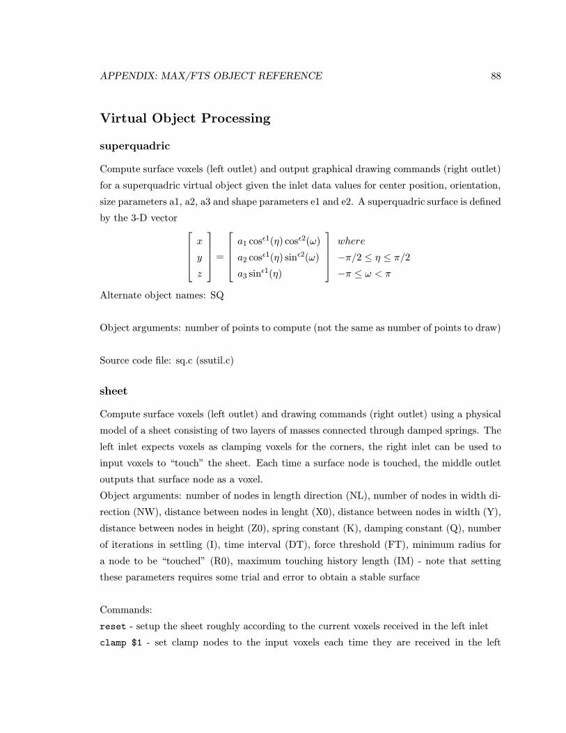
APPENDIX: MAX/FTS OBJECT REFERENCE 88
Virtual Object Processing
superquadric
Compute surface voxels (left outlet) and output graphical drawing commands (right outlet)
for a superquadric virtual object given the inlet data values for center position, orientation,
size parameters a1, a2, a3 and shape parameters e1 and e2. A superquadric surface is defined
by the 3-D vector x
y
z
=
a1 cosε1(η) cosε2(ω)
a2 cosε1(η) sinε2(ω)
a3 sinε1(η)
where
−π/2 ≤ η ≤ π/2
−π ≤ ω < π
Alternate object names: SQ
Object arguments: number of points to compute (not the same as number of points to draw)
Source code file: sq.c (ssutil.c)
sheet
Compute surface voxels (left outlet) and drawing commands (right outlet) using a physical
model of a sheet consisting of two layers of masses connected through damped springs. The
left inlet expects voxels as clamping voxels for the corners, the right inlet can be used to
input voxels to “touch” the sheet. Each time a surface node is touched, the middle outlet
outputs that surface node as a voxel.
Object arguments: number of nodes in length direction (NL), number of nodes in width di-
rection (NW), distance between nodes in lenght (X0), distance between nodes in width (Y),
distance between nodes in height (Z0), spring constant (K), damping constant (Q), number
of iterations in settling (I), time interval (DT), force threshold (FT), minimum radius for
a node to be “touched” (R0), maximum touching history length (IM) - note that setting
these parameters requires some trial and error to obtain a stable surface
Commands:
reset - setup the sheet roughly according to the current voxels received in the left inlet
clamp $1 - set clamp nodes to the input voxels each time they are received in the left

APPENDIX: MAX/FTS OBJECT REFERENCE 89
inlet ($1 = none: do not clamp anything, corners: clamp only corner nodes such that
the surface extends from the fingers, Rcorners: clamp only right corner nodes such that
the surface extends from the fingers, Lcorners: clamp only left corner nodes such that the
surface extends from the fingers, corners: clamp only corner nodes such that the surface
is perpendicular to the fingers)
fix $1 - fix the sheet, i.e. nodes cannot move ($1 = none: do not fix anything, all: fix all
nodes, clamp: fix only the clamp nodes, corners: fix only the corner nodes, Rcorners: fix
only the right corner nodes, Lcorners: fix only the corner nodes)
draw $1 - output drawing command sheetCoords to draw the surface (0 = top layer only,
1 = both layers)
clear - output drawing command sheetCoords with NW = 0 and NL = 0 to clear the
graphics
drawF $1 $2 $3 - output line drawing commands to draw the forces using a color specified
by r g b values on the nodes
drawTF $1 $2 $3 - output line drawing commands to draw only the forces of touched nodes
using a color specified by r g b values (0 0 0 turns drawing off, use clearF to erase existing
forces from the display)
clearF - output line drawing commands to clear all the drawn forces on the nodes
setX0 $1 - set the value of X0 to $1
setY0 $1 - set the value of Y0 to $1
setZ0 $1 - set the value of Z0 to $1
setK $1 - set the value of K to $1
setQ $1 - set the value of Q to $1
setI $1 - set the value of I to $1
setDT $1 - set the value of DT to $1
setFT $1 - set the value of FT to $1
setR0 $1 - set the value of R0 to $1
setIM $1 - set the value of IM to $1
printTime - print time in ms required to compute complete dataset
printTTime - print time in ms required to compute complete dataset and send it out the
outlet
Source code file: sheet.c (ism.c, ssutil.c)
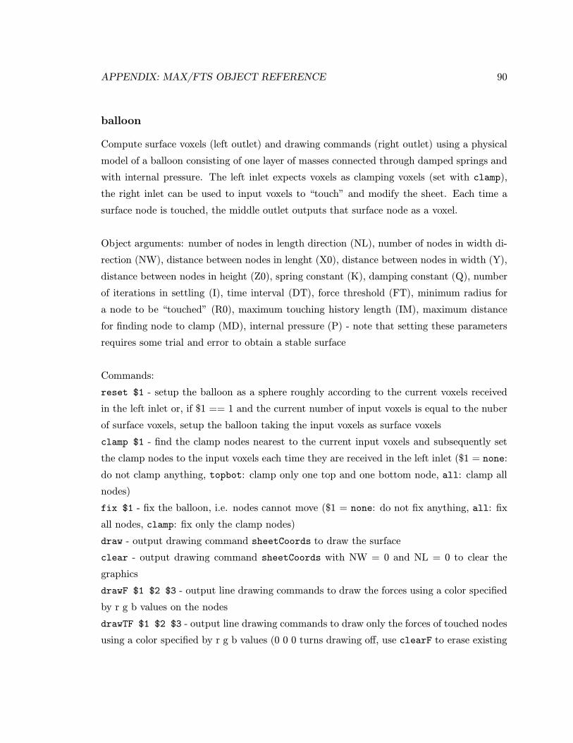
APPENDIX: MAX/FTS OBJECT REFERENCE 90
balloon
Compute surface voxels (left outlet) and drawing commands (right outlet) using a physical
model of a balloon consisting of one layer of masses connected through damped springs and
with internal pressure. The left inlet expects voxels as clamping voxels (set with clamp),
the right inlet can be used to input voxels to “touch” and modify the sheet. Each time a
surface node is touched, the middle outlet outputs that surface node as a voxel.
Object arguments: number of nodes in length direction (NL), number of nodes in width di-
rection (NW), distance between nodes in lenght (X0), distance between nodes in width (Y),
distance between nodes in height (Z0), spring constant (K), damping constant (Q), number
of iterations in settling (I), time interval (DT), force threshold (FT), minimum radius for
a node to be “touched” (R0), maximum touching history length (IM), maximum distance
for finding node to clamp (MD), internal pressure (P) - note that setting these parameters
requires some trial and error to obtain a stable surface
Commands:
reset $1 - setup the balloon as a sphere roughly according to the current voxels received
in the left inlet or, if $1 == 1 and the current number of input voxels is equal to the nuber
of surface voxels, setup the balloon taking the input voxels as surface voxels
clamp $1 - find the clamp nodes nearest to the current input voxels and subsequently set
the clamp nodes to the input voxels each time they are received in the left inlet ($1 = none:
do not clamp anything, topbot: clamp only one top and one bottom node, all: clamp all
nodes)
fix $1 - fix the balloon, i.e. nodes cannot move ($1 = none: do not fix anything, all: fix
all nodes, clamp: fix only the clamp nodes)
draw - output drawing command sheetCoords to draw the surface
clear - output drawing command sheetCoords with NW = 0 and NL = 0 to clear the
graphics
drawF $1 $2 $3 - output line drawing commands to draw the forces using a color specified
by r g b values on the nodes
drawTF $1 $2 $3 - output line drawing commands to draw only the forces of touched nodes
using a color specified by r g b values (0 0 0 turns drawing off, use clearF to erase existing

APPENDIX: MAX/FTS OBJECT REFERENCE 91
forces from the display)
clearF - output line drawing commands to clear all the drawn forces on the nodes
setX0 $1 - set the value of X0 to $1
setY0 $1 - set the value of Y0 to $1
setZ0 $1 - set the value of Z0 to $1
setK $1 - set the value of K to $1
setQ $1 - set the value of Q to $1
setI $1 - set the value of I to $1
setDT $1 - set the value of DT to $1
setFT $1 - set the value of FT to $1
setR0 $1 - set the value of R0 to $1
setIM $1 - set the value of IM to $1
setMD $1 - set the value of MD to $1
setP $1 - set the value of P to $1
printTime - print time in ms required to compute complete dataset
printTTime - print time in ms required to compute complete dataset and send it out the
outlet
Source code file: balloon.c (ism.c, ssutil.c)
Feature Computation
fitEllipsoid
Compute the ellipsoid parameters (outlets output center position, orientation, size param-
eters a1, a2, a3) that best fit a list of positions as input in the left inlet.
Alternate object names: fitE, fe
Commands:
boundByHands - if the input data is a position list representing both hands, scale the size of
the ellipsoid to be within the given positions
printTime - print time in ms required to compute complete parameter set
printTTime - print time in ms required to compute complete parameter set and send it out
APPENDIX: MAX/FTS OBJECT REFERENCE 92
the outlets
Source code file: fe.c (nrutil.c, ssutil.c)
fitSuperquadric
Compute the superquadric parameters (outlets output center position, orientation, size pa-
rameters a1, a2, a3 and shape parameters e1 and e2) that best fit a list of positions as input
in the left inlet.
Alternate object names: fitSuperquad, fitSQ, fSQ, fsq
Commands:
boundByHands - if the input data is a position list representing both hands, scale the size of
the ellipsoid to be roughly within the given positions
printTime - print time in ms required to compute complete parameter set
printTTime - print time in ms required to compute complete parameter set and send it out
the outlets
Source code file: fsq.c (nrutil.c, ssutil.c)
fitPoly
Compute upto 3 polynomial parameters (outlets output the polynomial coefficients) that
best fit a list of positions (only x and y data are used) as input in the left inlet.
Source code file: fpoly.c (nrutil.c, ssutil.c)
fitPlane
Compute the parameters of a plane (outlets output normal vector as a position, Zis and chi
square) that best fit a list of positions as input in the left inlet.
Alternate object names: fp
APPENDIX: MAX/FTS OBJECT REFERENCE 93
Source code file: fp.c (nrutil.c, ssutil.c)
kappa3D
Compute the average curvature (left outlet) computed from a list of voxels representing a
3D surface with width NW as input (left inlet).
Commands:
width $1 - set the NW to $1
Source code file: curv.c (nrutil.c, ssutil.c)
kappa2D
Compute the average curvature (left outlet) computed from a list of positions representing
a 2D curve (left inlet).
Source code file: curv.c (nrutil.c, ssutil.c)
Miscellaneous
unpackcg
Unpack a list message coming from the cyberglove object as separate floats for each sensor.
Alternate object names: upcg
Object arguments: at most 18 character strings (cmc rot, mcp1 flex, pip1 flex, cmc abd,
mcp2 flex, pip2 flex, mcp3 flex, pip3 flex, mcp3 abd, mcp4 flex, pip4 flex, mcp4 abd, mcp5 flex,
pip5 flex, mcp5 abd, palm arch, wrist flex, wrist abd) indicating which sensors should out-
put (and to which outlet).
Source code file: packPH.c (ssutil.c)
APPENDIX: MAX/FTS OBJECT REFERENCE 94
unPack
Unpack a list of hand, voxel, position or orientation data structures as separate data struc-
tures.
Object arguments: number of outlets, data format (“hand”, “voxel”, “position” or “ori-
entation”)
Source code file: packPH.c (ssutil.c)
Pack
Pack data structures received in the inlets into a list of hand, voxel, position or orientation
data structures.
Object arguments: number of inlets, data format (“hand”, “voxel”, “position” or “ori-
entation”)
source code file: packPH.c (ssutil.c)
sin, asin, cos, acos, tan, atan
Compute the geometric functions of the value(s) received in the inlet. When a bang is
received the last computed value(s) are output.
Object arguments: initial output value
Source code file: math.c (ssutil.c)
count
Count the bangs in the left inlet modulo the maximum count (can be set with right most
inlet), increase the count with 1 (default) or the value received in the middle inlet.
Object arguments: maximum count value
Commands: up $1 - set the increment to 1 or $1
down $1 - set the increment to -1 or $1
up $1 - set the increment to 0 or $1
APPENDIX: MAX/FTS OBJECT REFERENCE 95
jump $1 - add $1 to the count modulo the maximum count value
max $1 - set the maximum count value to $1
jump $1 - set the count to $1 modulo the maximum count value
Source code file: count.c (ssutil.c)
Appendix: Video Documentation
A video entitled “Sound Sculpting” was made, documenting and explaining the implemented
system. The contents of the video are as follows:
• Intro - preliminary shots of the system used in performance and motivation of the
research [0:00:14 - 0:01:42].
• Development Environment - Schematic diagram and description of the system
components [0:01:45 - 0:02:39].
• Manipulation - Demonstration of manipulation methods as described in section im-
plemented for the rubber sheet [0:02:43 - 0:04:09] and balloon [0:04:09 - 0:04:47] models.
• Mapping - Demonstration of sonification methods as described in section imple-
mented for the rubber sheet [0:04:50 - 0:07:44] and balloon [0:07:47 - 0:10:02] models.
• Show Time - Performance of music defined by MIDI sequences, using two hands for
manipulation of the rubber sheet [0:10:07 - 0:11:09] and balloon [0:11:12 - 0:11:48]
models.
• Show Time - Performance of music defined by MIDI sequences using left hand only
for manipulation the rubber sheet [0:11:51 - 0:12:36] and balloon [0:12:41 - 0:13:09]
models.
96
Bibliography
[1] Adriano Abbado. “Perceptual correspondences of abstract animation and synthetic
sound.” Leonardo, electronic art supplemental issue, 3-5. Oxford, UK: Pergamon Press,
1988.
[2] Tim Anderson and Debbie Hearn. “Using hyperinstruments for the redistribution of
the performance control interface” Proceedings of the international computer music
conference (Aarhus, Denmark), 183-184. San Francisco CA, USA: International com-
puter music association, 1994.
[3] Craig Anderton. “STEIM: In the land of alternate controllers.” Keyboard, (1994),
August, 54-62.
[4] Gerard Assayag. “Visual programming in music.” Proceedings of the international
computer music conference (Banff, Canada), 73-76. San Francisco CA, USA: Interna-
tional computer music association, 1995.
[5] Robin Bargar, Bryan Holloway, Xavier Rodet and Chris Hartman. “Defining spec-
tral surfaces.” Proceedings of the international computer music conference (Banff,
Canada), 373-376. San Francisco CA, USA: International computer music associa-
tion, 1995.
[6] Massimo Bergamasco. “Manipulation and exploration of virtual objects.” In: N. Mag-
nenat Thalmann and D. Thalman (eds.), Artificial life and virtual reality, 149-159.
New York, NY, USA: Wiley, 1994.
[7] Mark Bolas and Phil Stone. “Virtual mutant theremin.” Proceedings International
Computer Music Conference (San Jose, California, USA), 360-361. International com-
puter music association, San Francisco, CA, USA, 1992.
97
BIBLIOGRAPHY 98
[8] Bert Bongers. “The use of active tactile and force feedback in timbre controlling elec-
tronic instruments.” Proceedings international computer music conference (Aarhus,
Denmark), 171-174. San Francisco, CA, USA: The international computer music as-
sociation, 1994.
[9] Ch. Brechbuhler, G. Gerig, and O. Kuhler. “Parametrization of closed surfaces for
3D shape description.” Computer vision and image understanding, 61 (1995), No. 2,
March, 154-170.
[10] Bill Buxton and Brad A. Myers. “A study of two-handed input.” Proceedings of CHI86,
321-326. New York, NY, USA: ACM, 1986.
[11] Claude Cadoz, A. Luciani and Jean-loup Florens. “CORDIS-ANIMA: A modeling and
simulation system for sound and image synthesis - the general formalism.” Computer
music journal, 17 (1993), No. 4 (spring), 19-29.
[12] Claude Cadoz, L. Lisowski and Jean-loup Florens. “A modular feedback keyboard
design.” Computer music journal 14 (1990), No. 2, 47-51.
[13] Claude Cadoz, A. Luciani and Jean-loup Florens. “Responsive input devices and sound
synthesis by simulation of instrumental mechanisms: The CORDIS system.” Com-
puter music journal, 8 (1984), No. 3, 60-73.
[14] Antonio Camurri, A. Catorcini, C. Innocenti and A. Massari. “Music and multimedia
knowledge representation and reasoning: the HARP system.” Computer music journal
19 (1995), No. 2, 34-58.
[15] Stuart K. Card, J.D. Mackinlay and G.G. Robertson. “The design space of input
devices.” Proceedings of the 1990 conference on human factors in computing systems
(CHI ’90), 117-124. New York, NY, USA: The Association for Computing Machinery,
1990.
[16] Brad Cariou. “The aXiO MIDI controller.” Proceedings of the International Computer
Music Conference (Aarhus, Denmark), 163-166. San Francisco CA, USA: International
computer music association, 1994.
BIBLIOGRAPHY 99
[17] Chris Chafe. “Tactile audio feedback.” Proceedings international computer music con-
ference (Tokyo, Japan), 76-79. San Francisco, CA, USA: International computer music
association.
[18] Insook Choi, Robin Bargar and Camille Goudeseune. “A manifold interface for a
high dimensional control interface.” Proceedings of the international computer music
conference (Banff, Canada), 385-392. San Francisco CA, USA: International Computer
Music Association, 1995.
[19] R.L. Doerschuk. “The life and legacy of Leon Theremin.” Keyboard, (1994) February,
48-68.
[20] Gerhard Eckel and R. Gonzalez-Arroyo. “Musically salient control abstractions for
sound synthesis.” Proceedings International Computer Music Conference (Aarhus,
Denmark), 256-259. San Francisco, CA, USA: The International Computer Music
Association, 1994.
[21] S. Sidney Fels and Geoffrey E. Hinton. “Glove-TalkII: A neural network interface which
maps gestures to parallel formant speech synthesizer controls.” IEEE Transactions on
Neural Networks, 9 (1998), No. 1, 205-212.
[22] S. Sidney Fels and Geoffrey E. Hinton. “Glove-Talk: a neural network interface be-
tween a data-glove and a speech synthesizer.” IEEE Transactions on Neural Networks,
4 (1993), No. 1, 2-8.
[23] Jean-loup Florens and Claude Cadoz. “The physical model: modeling and simulating
the instrumental universe.” In: Giovanni De Poli, Aldo Picalli and Curtis Roads (eds.),
Representations of musical signals, 227-268. Cambridge MA, USA: MIT Press.
[24] Tinsley A. Galyean. “Sculpting: An Interactive Volumetric Modeling Technique.”
ACM Computer Graphics, 25 (1991), No. 4 (SIGGRAPH ’91, Las Vegas, 28 July - 2
August 1991), 267-274.
[25] W. Garner. “The relationship between colour and music.” Leonardo, 11 (1978), 225-
226.
[26] Theo Goldberg and Gunther Schrack. “Computer-aided correlation of musical and
visual structures.” Leonardo 19 (1986), No. 1, 11-17.
BIBLIOGRAPHY 100
[27] P. Hartono, K. Asano, W. Inoue, S. Hashimoto. “Adaptive timbre control using ges-
ture.” Proceedings International Computer Music Conference (Aarhus, Denmark),
151-158. San Francisco CA, USA: International Computer Music Association, 1994.
[28] Barbara Hero. “Paintings based on relative pitch in music.” Leonardo, 8 (1975), 13-19.
[29] Koichi Hirota and Michitaka Hirose. “Providing force feedback in virtual environ-
ments.” IEEE Computer graphics and applications, 1995, September, 22-30.
[30] Bart Hopkin. Gravikords, whirlies and pyrophones - experimental musical instruments.
Roslyn, NY, USA: Ellipsis arts, 1996.
[31] Thea Iberall and Christine L. MacKenzie. “Opposition space and human prehension.”
In: S.T. Venkataraman and Thea Iberall (eds.), Dextrous robot hands, 32-54. New
York, NY, USA: Springer Verlag, 1990.
[32] R.J.K. Jacob, L.E. Sibert, D.C. McFarlane and M.Jr. Preston Mullen. “Integrality and
separability of input devices.” ACM transactions on computer-human interaction, 1
(1994), No. 1, 3-26.
[33] David A. Jaffe and W. Andrew Schloss. “A virtual piano concerto - coupling of
the Mathews/Boie radiodrum and the Yamaha Disklavier grand piano in the seven
wonders of the ancient world.” Proceedings international computer music conference
(Aarhus, Denmark), 192-195. San Francisco, CA, USA: International computer music
association, 1994.
[34] Lynette Jones. “Dextrous hands: Human, prosthetic and robotic.” Presence, 6 (1997),
No. 1 (February), 29-56.
[35] Paul Kabbash, William Buxton and Abigail Sellen. “Two-Handed Input in a Com-
pound Task.” Proceedings of CHI ’94, 417-423. 1994.
[36] A. Kendon. “How gestures can become like words.” In:F. Potyatos, Crosscultural per-
spectives in nonverbal communication, Toronto, 131-141. Canada: Hogrefe, 1988.
[37] Ross Kirk, Andy Hunt and Richard Orton. “Audio-visual instruments in live perfor-
mance.” Proceedings international computer music conference (Banff, Canada), 595-
596. San Francisco CA, USA: International computer music association, 1995.
BIBLIOGRAPHY 101
[38] R. Benjamin Knapp and Hugh Lusted. “A bioelectric controller for computer music
applications.” Computer music journal, 14 (1990), No. 1, 42-47.
[39] Gregory Kramer. Auditory Display. Sonification, audification and auditory interfaces.
Proceedings volume XVIII, Santa Fe Institute, Studies in the sciences of complexity.
New York, NY, USA: Addison-Wesley, 1994.
[40] Volker Krefeld. “The hand in the web: An interview with Michel Waisvisz.” Computer
music journal, 14 (1990), No. 2, 28-33.
[41] Myron W. Krueger. Artificial reality, 2nd edition. Reading, MA, USA: Addison Wesley,
1990.
[42] T.K. Landauer. “Research methods in human computer interaction.” In: M. Helander,
Handbook of human computer interaction, 905-928. Amsterdam, The Netherlands:
Elsevier Science Publishers, 1988.
[43] Jaron Lanier. “The sound of one hand.” http://www.well.com/user/jaron/vr.html
[44] Michael Lee, Adrian Freed and David Wessel. “Real time neural network processing
of gestural and acoustic signals.” Proceedings international computer music confer-
ence (Burnaby, BC, Canada). San Francisco, CA, USA: International computer music
association, 1991.
[45] E.A. Lord and C.B. Wilson. The mathematical description of shape and form. New
York, NY, USA: John Wiley and sons, 1984.
[46] Tod Machover and Joe Chung. “Hyperinstruments: Musically intelligent and interac-
tive performance and creativity systems.” Proceedings international computer music
conference (Columbus, OH, USA). San Francisco, CA, USA: International computer
music association, 1989.
[47] Christine L. MacKenzie and Thea Iberall. The grasping hand. Amsterdam, The
Netherlands: Elsevier Science Publishers, 1994.
[48] Vera Maletic. Body space expression: the development of Rudolf Laban’s movement
and dance concepts. Berlin, Germany: Mouton de Gruyter, 1987.
BIBLIOGRAPHY 102
[49] Max Mathews and W. Andrew Schloss. “The radiodrum as a synthesis controller.”
Proceedings international computer music conference (Columbus, OH, USA). San
Francisco, CA, USA: International computer music association, 1989.
[50] O. Mattis and Robert Moog. “Leon Theremin: Pulling music out of thin air.” Key-
board, (1992) February, 45-54.
[51] David McNeill. Hand and mind: what gestures reveal about thought. Chicago, USA:
University of chicago press, 1992.
[52] Paul Modler. “Interactive control of musical structures by hand gestures.” Proceedings
of the fifth Brazilian symposium on computer music, (Belo Horizonte, Minas Gerais,
Brazil, 3-5 August 1998, during the 18th annual Congres of the Brazilian computer
society), 143-150. Belo Horizonte, MG, Brazil: Universidade Federal de Minas Gerais,
1998.
[53] F. Richard Moore. “The dysfunctions of MIDI.” Computer music journal, 12 (1988),
No. 1, 19-28.
[54] H. Morita, S. Hashimoto and S. Ohteru. “A computer music system that follows a
human conductor.” IEEE Computer 1991, (July), 44-53.
[55] Axel G.E. Mulder. Design of virtual 3D instruments for sound control. PhD. the-
sis. Burnaby, BC, Canada: Simon Fraser University, 1998. Available on the web
at http://www.cs.sfu.ca/∼amulder/personal/vmi/AM98-thesis.ps.Z (postscript) and
http://www.cs.sfu.ca/∼amulder/personal/vmi/AM98-thesis.pdf (portable document
format).
[56] Axel G.E. Mulder and S. Sidney Fels. “Sound Sculpting: Performing with Virtual
Musical Instruments.” Proceedings of the fifth Brazilian symposium on computer mu-
sic, (Belo Horizonte, Minas Gerais, Brazil, 3-5 August 1998, during the 18th annual
congres of the Brazilian computer society), 151-164. Belo Horizonte, MG, Brazil: Uni-
versidade Federal de Minas Gerais, 1998.
[57] Axel G. E. Mulder, S. Sidney Fels and Kenji Mase. “Mapping virtual object manipula-
tion to sound variation.” IPSJ SIG notes, 97 (1997), No. 122, 97-MUS-23 (USA/Japan
intercollege computer music festival, Tokyo, Japan, 13-16 december 1997), 63-68.
BIBLIOGRAPHY 103
[58] Axel G. E. Mulder. “Getting a GRIP on alternate controllers: Addressing the vari-
ability of gestural expression in musical instrument design.” Leonardo music journal,
6 (1996), 33-40.
[59] Axel G. E. Mulder. “Hand gestures for HCI,” Technical report, NSERC Hand centered
studies of human movement project. Burnaby, BC, Canada: Simon Fraser University,
1996. Available on the WWW at http://www.cs.sfu.ca/∼amulder/personal/vmi/HCI-
gestures.htm
[60] Axel G. E. Mulder. “Human movement tracking technology,” Technical re-
port, NSERC Hand centered studies of human movement project. Burnaby,
BC, Canada: Simon Fraser University, 1994. Available on the WWW at
http://www.cs.sfu.ca/∼amulder/personal/vmi/HMTT.pub.html
[61] Axel G. E. Mulder. “Virtual musical instruments: Accessing the sound synthe-
sis universe as a performer.” Proceedings of the first Brazilian symposium on com-
puter music, (Caxambu, Minas Gerais, Brazil, 2-4 August 1994, during the 14th
annual congres of the Brazilian computer society), 243-250. Belo Horizonte, MG,
Brazil: Universidade Federal de Minas Gerais, 1994. Available on the WWW at
http://www.cs.sfu.ca/∼amulder/personal/vmi/BSCM1.ps.Z
[62] Michel Naranjo and Assuh Koffi (1988). “Geometric image modeling of the musical
object” Leonardo, Electronic art supplemental issue, 69-72. Oxford, UK: Pergamon
Press, 1988.
[63] Gary Ng. A virtual environment for instrumental music performance. MSc. thesis.
Manchester, UK: department of computer science, University of Manchester, 1994.
[64] Laurence Nigay and Joelle Coutaz. “A design space for multimodal systems: Con-
current processing and data fusion.” Proceedings of the conference of human factors
in computing, InterCHI 93 (Amsterdam, Netherlands), 172-178. Reading, MA, USA:
Addison-Wesley, 1993.
[65] D.A. Norman. The psychology of everyday things. New York, USA: Doubleday, 1988.
[66] Jack Ox and Peter Frank. “The systematic translation of musical compositions into
paintings.” Leonardo, 17 (1984), No. 3, 152-158.
BIBLIOGRAPHY 104
[67] Joe Paradiso. “New ways to play.” IEEE Spectrum, 1997, No. 12 (December), 18-30.
[68] Joseph A. Paradiso and Neil Gershenfeld. “Musical applications of electric field sens-
ing.” Computer music journal, 21 (1997), No. 2, 69-89.
[69] S. Pheasant. Bodyspace: Anthropometry, ergonomics and design. London, UK: Taylor
and francis, 1986.
[70] Nick Porcaro, Pat Scandalis, Julius Smith, David Jaffeand Tim Stilson. “Synthbuilder
demonstration - A graphical real-time synthesis, processing and performance sys-
tem.” Proceedings international computer music conference (Banff, Canada), 61-62.
San Francisco CA, USA: International computer music association, 1995.
[71] Jeff Pressing. “Cybernetic issues in interactive performance systems.” Computer music
journal, 14 (1990), No. 1, 12-25.
[72] Jeff Pressing. “Non-keyboard controllers.” In: Jeff Pressing (ed.), Synthesizer perfor-
mance and real-time techniques. Madison, Wisconsin, USA: A-R editions, 1992.
[73] Miller Puckette. “FTS: A real time monitor for multiprocessor music synthesis.” Com-
puter music journal, 15 (1991), No. 3, 58-67.
[74] Miller Puckette. “Combining event and signal processing in the MAX graphical pro-
gramming environment.” Computer music journal, 15 (1991), No. 3, 68-77.
[75] Miller Puckette. “Nonobvious roles for electronics in performance enhancement.” Pro-
ceedings international computer music conference (Tokyo, Japan), 134-137. San Fran-
cisco, CA, USA: International computer music association, 1993.
[76] William Putnam and R. Benjamin Knapp. “Input/Data Acquisition System De-
sign for Human Computer Interfacing.” Available on the web at http://www-
ccrma.stanford.edu/CCRMA/Courses/252/sensors/sensors.html.
[77] Joseph Butch Rovan, Marcelo M. Wanderley, Shlomo Dubnov and Philippe Depalle.
“Instrumental gestural mapping strategies as expressivity determinants in computer
music performance.” Proceedings of the AIMI international workshop on Kansei -
the technology of emotion (Genova, Italy, 3-4 october 1997), 87-90. Genova, Italia:
Universita di Genova, 1997.
BIBLIOGRAPHY 105
[78] Dean Rubine and Paul McAvinney. “Programmable finger tracking instrument con-
trollers.” Computer music journal, vol 14 (1990), No. 1 (spring), 26-41.
[79] Joel Ryan. “Some remarks on musical instrument design at STEIM.” Contemporary
music review, 6 (1991), No. 1, 3-17.
[80] W. Andrew Schloss. “Recent advances in the coupling of the language MAX with
the Mathews/Boie radio drum. Proceedings international computer music conference
(Glasgow, UK), 398-400. San Francisco, CA, USA: International computer music as-
sociation, 1990.
[81] B. Shackel. “Human factors and usability.” In: J. Preece and L. Keller (Eds.), Human-
computer interaction: Selected readings. Englewood Cliffs, NJ, USA: Prentice Hall,
1990.
[82] Karun B. Shimoga. A survey of perceptual feedback issues in dexterous telemanipula-
tion: part II. Finger touch feedback.” Proceedings of the IEEE Virtual reality annual
international symposium (Seattle, WA, USA, September 18-22 1993), 271-279. New
York, NY, USA: IEEE.
[83] Karun B. Shimoga. “A survey of perceptual feedback issues in dextrous telemanipu-
lation: part I. Finger force feedback.” Proceedings of the IEEE Virtual reality annual
international symposium (Seattle Washington, September 18-22 1993), 263-270. New
York, NY, USA: IEEE.
[84] Ben Shneidermann. Designing the user interface. Reading, Massachussets, USA:
Addison-Wesley, 1992.
[85] John A. Sloboda. “Music performance: expression and the development of excellence.”
In: R. Aiello (ed.), Music perception, 152-169. New York, NY, USA: Oxford University
Press, 1994.
[86] J.R. Smith. “Field mice: Extracting hand geometry from electric field measurements.”
IBM systems journal, 25 (1996), No. 3-4, 587-608.
[87] Franc Solina and Ruzena Bajcsy. “Recovery of parametric models from range images:
the case for superquadrics with global deformations.” IEEE Transactions on pattern
analysis and machine intelligence, 12 (1990), No. 2 (February), 131-147.
BIBLIOGRAPHY 106
[88] David J. Sturman and David Zeltzer. “A design method for whole-hand human com-
puter interaction.” ACM transactions on information systems, 11 (1993), No. 3, 219-
238.
[89] David J. Sturman. “Whole hand input” Ph.D. thesis. Available at ftp://media-
lab.mit.edu /pub/sturman/WholeHandInput. Cambridge, MA: Massachusetts Insti-
tute of Technology, 1992.
[90] Atau Tanaka. “Musical technical issues in using interactive instrument technology with
application to the BioMuse.” Proceedings international computer music conference
(Tokyo, Japan), 124-126. San Francisco, CA, USA: International computer music
association, 1993.
[91] Raoul Tubiana. The Hand. Philadelphia, PA, USA: Saunders, 1981.
[92] Mark Vail. It’s Dr. Moog’s traveling show of electronic controllers. Keyboard, (1993)
March, 44-49.
[93] Roel Vertegaal. An evaluation of input devices for timbre space navigation. MPhil.
dissertation. Bradford, UK: Department of computing, University of Bradford, 1994.
[94] Roel Vertegaal. “An evaluation of input devices for use in the ISEE human-synthesizer
interface.” Proceedings international computer music conference (Aarhus, Denmark),
159-162. San Francisco CA, USA: International computer music association, 1994.
[95] Roel Vertegaal and Tamas Ungvary. “The sentograph: Input devices and the commu-
nication of bodily expression.” Proceedings international computer music conference
(Banff, Canada), 253-256. San Francisco CA, USA: International computer music as-
sociation, 1995.
[96] David M. Waxman. “Digital theremins: interactive musical experiences for amateurs
using electric field sensing.” MSc. thesis. Cambridge, MA, USA: MIT.
[97] Josie Wernecke. The inventor mentor. Reading, MA, USA: Addison Wesley, 1994.
[98] David Wessel. “Timbre space as a musical control structure.” Computer music journal,
3 (1979), No. 2, 45-52.
BIBLIOGRAPHY 107
[99] Alan Wexelblatt. “An approach to natural gesture in virtual environments.” ACM
Transactions on computer human interaction, 2 (1995), No. 3 (September), 179-200.
[100] 3Space Fastrak user’s manual revision F. Colchester, VT, USA: Polhemus Inc.
(http://www.polhemus.com), november 1993.
[101] CyberGlove user’s manual, Palo Alto, CA, USA: Virtual Technologies Inc.
(http://www.virtex.com), june 8, 1993.
[102] Dimensionbeam. Santa Monica, CA, USA: Interactive Light Inc., 1997. Documentation
available on the web at http://www.dimensionbeam.com/db/index.htm.
[103] I-Cube system manual. Vancouver, BC, Canada: Infusion Systems Ltd.
(http://www.infusionsystems.com), 1997.
[104] Lightning. Berkeley, CA, USA: Buchla and associates, 1997. Documentation available
on the web at http://www.buchla.com/index.shtml
[105] Laetitia Sonami. http://www.otherminds.org/Sonami.html
[106] Max/FTS documentation. Paris, France: Institut pour la Recherche de l’Acoustique et
Musique, 1997. Available through the WWW at http://www.ircam.fr/equipes/temps-
reel/fts/doc/.
[107] Miburi. Shizuoka, Japan: Yamaha Corp., 1997. Documentation available on the web
at http://www.yamaha.com
[108] Sensorband. http://wwwusers.imaginet.fr/∼atau/sensorband/index.html
[109] The Theremin home page. http://www.nashville.net/∼theremin/
[110] Troika Ranch. http://www.art.net/∼troika/troikahome.html
[111] Waisvisz archive. http://www.xs4all.nl/∼mwais