Design of the Retaining Wall Structures on the M4 Smart ... · Design of the Retaining Wall...
25
8 th Australian Small Bridges Conference Design of the Retaining Wall Structures on the M4 Smart Motorway Project, Sydney Kenny Luu, Amey, Australia Saman Zargarbashi, Arup, Australia ABSTRACT The M4 Smart Motorway project aims to introduce Intelligent Transport Systems (ITS) along the M4 Motorway between Pitt Street overpass at Mays Hill and Russell Street at Lapstone in Sydney. As part of this project, seventeen retaining walls are required to support the associated ramp widening works and the installation and maintenance of the ITS infrastructures. These retaining wall structures comprise many different wall types ranging from soil nailing, piled wall, L-shaped wall and a hybrid combination of an L-shaped wall supported on piles. The design of these retaining structures was required to overcome many constraints imposed by an existing site around one of the most congested motorways in Sydney. One of the key drivers in the selection of the wall types is to achieve constructability with minimum disruptions to the existing M4 motorway as well as the communities around the sites. These considerations were reflected in the design of the retaining wall structures located along the eastbound entry ramps at the M4 motorway interchanges with Burnett Street, Coleman Street and the M7 Motorway, respectively. This paper presents the key design aspects of the retaining wall structures on the M4 Smart Motorway project with a focus on the three specific structures at the above interchanges. 1. INTRODUCTION The M4 Smart Motorway (M4SM) project aims to introduce Intelligent Transport Systems (ITS) known as Smart Motorways along the M4 Motorway between Pitt Street overpass at Mays Hill and Russell Street at Lapstone. The project also applies Smart Motorway solutions to the Westconnex Stage 1A project which extends from Pitt Street east to Homebush Bay Drive. This upgrade project is referred to as the M4 Smart Motorway Project and is in the detailed design phase of development. The overall objective of the M4 Smart Motorway upgrade is to: • Enhance travel time and improve journey time reliability; • Enhance traffic throughput, efficiency and productivity; and • Enhance traffic safety.
Transcript of Design of the Retaining Wall Structures on the M4 Smart ... · Design of the Retaining Wall...
8th Australian Small Bridges Conference
Design of the Retaining Wall Structures on the M4 Smart Motorway
Project, Sydney
Kenny Luu, Amey, Australia
Saman Zargarbashi, Arup, Australia
ABSTRACT
The M4 Smart Motorway project aims to introduce Intelligent Transport Systems
(ITS) along the M4 Motorway between Pitt Street overpass at Mays Hill and Russell
Street at Lapstone in Sydney. As part of this project, seventeen retaining walls are
required to support the associated ramp widening works and the installation and
maintenance of the ITS infrastructures.
These retaining wall structures comprise many different wall types ranging from soil
nailing, piled wall, L-shaped wall and a hybrid combination of an L-shaped wall
supported on piles. The design of these retaining structures was required to
overcome many constraints imposed by an existing site around one of the most
congested motorways in Sydney. One of the key drivers in the selection of the wall
types is to achieve constructability with minimum disruptions to the existing M4
motorway as well as the communities around the sites. These considerations were
reflected in the design of the retaining wall structures located along the eastbound
entry ramps at the M4 motorway interchanges with Burnett Street, Coleman Street
and the M7 Motorway, respectively.
This paper presents the key design aspects of the retaining wall structures on the M4
Smart Motorway project with a focus on the three specific structures at the above
interchanges.
1. INTRODUCTION
The M4 Smart Motorway (M4SM) project aims to introduce Intelligent Transport Systems (ITS) known as Smart Motorways along the M4 Motorway between Pitt Street overpass at Mays Hill and Russell Street at Lapstone. The project also applies Smart Motorway solutions to the Westconnex Stage 1A project which extends from Pitt Street east to Homebush Bay Drive. This upgrade project is referred to as the M4 Smart Motorway Project and is in the detailed design phase of development. The overall objective of the M4 Smart Motorway upgrade is to:
• Enhance travel time and improve journey time reliability;
• Enhance traffic throughput, efficiency and productivity; and
• Enhance traffic safety.
8th Australian Small Bridges Conference
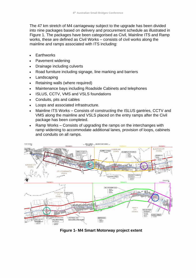
The 47 km stretch of M4 carriageway subject to the upgrade has been divided into nine packages based on delivery and procurement schedule as illustrated in Figure 1. The packages have been categorised as Civil, Mainline ITS and Ramp works, these are defined as Civil Works – consists of civil works along the mainline and ramps associated with ITS including:
• Earthworks
• Pavement widening
• Drainage including culverts
• Road furniture including signage, line marking and barriers
• Landscaping
• Retaining walls (where required)
• Maintenance bays including Roadside Cabinets and telephones
• ISLUS, CCTV, VMS and VSLS foundations
• Conduits, pits and cables
• Loops and associated infrastructure.
• Mainline ITS Works – Consists of constructing the ISLUS gantries, CCTV and VMS along the mainline and VSLS placed on the entry ramps after the Civil package has been completed.
• Ramp Works – Consists of upgrading the ramps on the interchanges with ramp widening to accommodate additional lanes, provision of loops, cabinets and conduits on all ramps.
Figure 1- M4 Smart Motorway project extent
8th Australian Small Bridges Conference
2. RETAINING WALLS STRUCTURES AND GENERAL CONSTRAINTS
On the M4 Smart Motorway (M4SM) project, 17 retaining wall structures are required
to accommodate the ramp widening works as well as the installation of the ITS
maintenance facilities. These retaining wall structures, some of which can be
substantial structures with retained heights up to 9.0m, comprise many different wall
types, including:
• Reinforced concrete L-shaped
• Solder piled wall
• Soil Nail Wall
• Reinforced Soil Wall
• Hybrid wall type comprising an L-shaped wall on piles
The design of the above retaining wall structures must consider all the constraints
associated with an urban brownfield project, more so on the heavily congested
existing M4 motorway corridor. The main constraints identified through the
investigation and stake holder consultation include:
• Existing infrastructures
• Existing utilities
• Limited available physical space for the structure footprints
• Constructablity as existing traffic flows on the motorway as well as on the associated ramps need to be maintained during construction.
• Environmental constraints
• Urban design requirements as the proposed retaining walls will be imposing structures which are highly visible to the road users as well as the nearby communities
• Feedback from the community
The wall types and the design details have been carefully selected to best meet all
the constraints listed above. Due to the physical constraints of the corridor and to
achieve the minimum project footprint , these retaining walls are often required to act
as supporting platforms for other proposed infrastructures, including traffic barriers,
noise walls, static signage and lighting poles.
3. DESIGN CRITERIA
3.1. Reference Documents and Engineering Design Standards
Table 1 provides the order of precedence for reference documents and engineering
design standards, applicable to the detail design of the retaining walls on the M4SM
project.
8th Australian Small Bridges Conference
Table 1: M4SM Reference Documents and Engineering Design Standards
Precedence Document
A The Description of Services
B Roads and Maritime publications, including Bridge Technical Directions and Specifications
C Australian Standards
D AUSTROADS Guides
E Other Roads and Maritime publications not referenced in Roads and Maritime Supplements to AustRoads Guides
F Others references and standards, as agreed with Roads and Maritime’s representative
The Bridge Design Standard AS5100-2004, including the AS/RMS5100.5 May 2015
Interim, is the primary design standard adopted in the design of the retaining wall
structures. The use of AS4678 was adopted only for the aspects of the retaining wall
design which AS5100.3 does not cover such as the calculation of the quasi-static
earthquake loading by the Mononobe-Okabe method.
3.2. Design Loadings
The following design loadings have been considered in the design of the retaining
walls. The design of the retaining walls has considered the combinations of these
loads with the appropriate load factors in accordance with AS5100.2 to produce the
worst effects on the structures.
3.2.1. Dead Loads
A dead load is considered as the weight of the parts of the structure that are structural elements, as well as any non-structural elements that are considered unlikely to vary during the construction process and use of the structure, such as traffic barriers. The nominal dead loads were calculated using the dimensions shown on the drawings and the appropriate material densities
3.2.2. Earth Pressure Loads
Both vertical and lateral earth pressures imposed from the soil were calculated on the basis of the soil parameters from either insitu material retained, or the imported material as suited. Overburden loads have been assessed based on the retained batters.
8th Australian Small Bridges Conference
3.2.3. Live Load Surcharge
Retaining walls supporting road pavement were designed for a surcharge live load of 20kPa, which diminishes over the height of the wall in accordance with AS5100.2 Clause 13.2. Retaining walls supporting footpaths or fill that is unlikely to be subjected to vehicular live loading were designed for a minimum surcharge live load of 10kPa, in accordance with the Section 4.5.12 of the Brief.
3.2.4. Construction Surcharge
The walls were checked for a temporary construction surcharge load of 10kPa. This allowance was noted on design drawings. If specific construction machinery is required, which may impose additional surcharge to the retaining wall structures, further design assessment is undertaken for the specific loadings.
3.2.5. Compaction Load
A nominal locked-in compaction pressure of 10kPa was considered in the design of the retaining walls. This pressure was taken to be a uniform lateral pressure on the wall starting at finished ground surfaced level and continuing to the intersection with the active earth pressure stress distribution. The intersection point is approximately 1.5m below the finished ground surfaced level, assuming the back fill soil has an
internal friction angle ’ =30o with a density of =20kN/m3. The compaction equipment in the zone immediately adjacent to the retaining structures was limited to the use of 1.5 tonne ‘walk behind pedestrian’ roller or hand-held plate compactors to control the locked in compaction.
3.2.6. Hydrostatic Pressure
The design loading for hydrostatic pressures was not included as an effective drainage layer behind the wall is provided and the ground water levels encountered in the nearby boreholes are below the wall level. However, a load case was analysed using a lower factor of safety of 1.0 assuming failure of the drainage system. A height of water of one-third the wall height is used where the design loading for hydrostatic pressures was included.
3.2.7. Barrier Loads
Where a retaining wall structure is required to support a traffic barrier, the retaining wall must be designed to resist the vehicle impact loading. The magnitude of the impact loading is dependent on the required performance level of the barrier, which is determined via a risk assessment process detailed in Appendix B, AS5100.1. In general, the results of the risk assessment, using the projected AADT for 2031 and the relevant percentage of commercial vehicles on the mainline and at the ramps, indicated regular performance level barriers would be adequate for the ramp retaining walls whilst medium performance level barriers would be required for the maintenance retaining walls along the mainline due to the higher design speed.

8th Australian Small Bridges Conference
The design barrier loads for the corresponding barrier performance levels were selected in accordance with AS5100.2 A2.1 and summarised in Table 2. For the L-shaped retaining walls, the stabilising effect of the vehicle surcharge was ignored in when the structures were checked for impact loadings. Table 2: Barrier Loads
Barrier performance level
Ultimate transverse outward load (kN)
Ultimate longitudinal or transverse inwards load (kN)
Vehicle contact length (m)
Ultimate vertical downward load (kN)
Vehicle contact length (m)
Regular 250 80 1.1 80 5.5
Medium 500 170 2.4 350 12.0
3.2.8. Earthquake Loads
The retaining walls were designed for earthquake loading in accordance with AS5100.2. For the retaining walls, the earthquake design category Cer was adopted in accordance with AS4678. The corresponding design parameters included structural classification type C, acceleration coefficient of 0.08 and a site factor of 1.0. The earthquake-induced lateral earth pressure was calculated based on the pseudo-static Mononobe-Okabe method as detailed in Appendix I, AS4678. The static active earth pressure component was factored by 1.5 and the dynamic earth pressure component was factored by 1.0 to determine the ULS design action on the walls.
3.2.9. Wind Loads
Where retaining walls are required to support the noise walls the design has to accommodate wind loads transferred through the supports of the noise walls. The wind pressure loads acting on the noise walls were calculated in accordance with Roads and Maritime Specification R271 and Roads and Maritime Noise Wall Design Guidance NR271. 3.3. Retaining Wall Drainage
The drainage system for the retaining walls has been provided as stipulated in AS5100.3, Roads and Maritime Specification B30, and AS4678. It is an NSW Roads and Maritime requirement that that all retaining wall drainage to be connected to the existing sub-surface drainage systems and weepholes were not to be used to minimise future maintenance works.

8th Australian Small Bridges Conference
4. CASE STUDIES
4.1. CASE STUDY 1: RETAINING WALL RW1- BURNETT STREET EASTBOUND ENTRY RAMP
The Burnett Street eastbound entry ramp has been proposed to be widened as part of the M4 Smart Motorway project. A retaining wall (RW1) is proposed to enable the ramp embankment widening approximately between mainline CH 11080 and CH 11270. In addition, the noise assessment at this location determined that a 5.0m noise wall is also required at this location. To minimise the extent of the ramp widening, this noise wall is to be supported on top of the retaining wall. The retaining wall RW1 is also required to support lighting poles at three locations along its length.
4.1.1. Existing Site Constraints
The primary constraint at this site is an existing retaining wall which extends approximately parallel to the proposed retaining wall RW1 alignment to the north along the local street, Auburn Street. Limited non-destructive investigation by RMS suggested that the existing retaining wall is an L-shaped concrete wall with a base slab less than 1.5 m. No structural detail on the existing wall was provided to the design team. An existing overhead power line runs parallel to the wall alignment. To facilitate the construction of the proposed retaining wall RW1, the power line will have to be relocated, potentially to underground. The construction of the retaining wall is likely to require access from the below Auburn Street, which services the local residents as well as a school nearby. Therefore, the construction staging must maintain this access at all times.
4.1.2. Geotechnical Subsurface Conditions
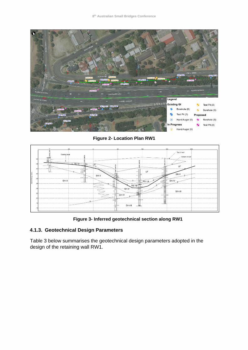
The available geotechnical data indicates that the subsurface stratigraphy along the wall comprises a variable thickness of fill, typically firm to very stiff gravely clay or clayey gravel and cobbles, underlain by a relatively thin stiff to hard residual soil and shale bedrock. Shale bedrock has been encountered between RL +25.6 m and RL +33.3 m AHD. A plan and geotechnical section along the wall are presented in Figure 2 and Figure 3, respectively. The groundwater level was measured at approximately at RL +29.0 m AHD (~ 7 m depth below the top of RW1).
8th Australian Small Bridges Conference
Figure 2- Location Plan RW1
Figure 3- Inferred geotechnical section along RW1
4.1.3. Geotechnical Design Parameters
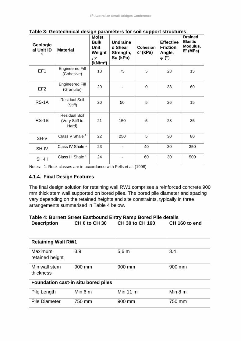
Table 3 below summarises the geotechnical design parameters adopted in the
design of the retaining wall RW1.
8th Australian Small Bridges Conference
Table 3: Geotechnical design parameters for soil support structures
Geological Unit ID
1
Material
Moist Bulk Unit Weight, 𝜸 (kN/m3)
Undrained Shear Strength, Su (kPa)
Cohesion
c' (kPa)
Effective Friction Angle, 𝝋′(°)
Drained Elastic Modulus, E’ (MPa)
EF1
Engineered Fill
(Cohesive) 18 75 5 28 15
EF2
Engineered Fill
(Granular) 20 - 0 33 60
RS-1A
Residual Soil
(Stiff) 20 50 5 26 15
RS-1B
Residual Soil
(Very Stiff to
Hard)
21 150 5 28 35
SH-V Class V Shale 1 22 250 5 30 80
SH-IV Class IV Shale 1 23 - 40 30 350
SH-III Class III Shale 1 24 - 60 30 500
Notes: 1. Rock classes are in accordance with Pells et al. (1998)
4.1.4. Final Design Features
The final design solution for retaining wall RW1 comprises a reinforced concrete 900
mm thick stem wall supported on bored piles. The bored pile diameter and spacing
vary depending on the retained heights and site constraints, typically in three
arrangements summarised in Table 4 below.
Table 4: Burnett Street Eastbound Entry Ramp Bored Pile details
Description CH 0 to CH 30 CH 30 to CH 160
CH 160 to end
Retaining Wall RW1
Maximum
retained height
3.9 5.6 m 3.4
Min wall stem
thickness
900 mm 900 mm 900 mm
Foundation cast-in situ bored piles
Pile Length Min 6 m Min 11 m Min 8 m
Pile Diameter 750 mm 900 mm 750 mm
8th Australian Small Bridges Conference
Pile Centre to
Centre Spacing
2250 mm 1800 mm 2250 mm
Rock socket
requirement
Min 4.0 m into
Class IV
Min 2.0 m into Class
III Shale/Sandstone
Min 2.0 m into
Class III
Shale/Sandstone
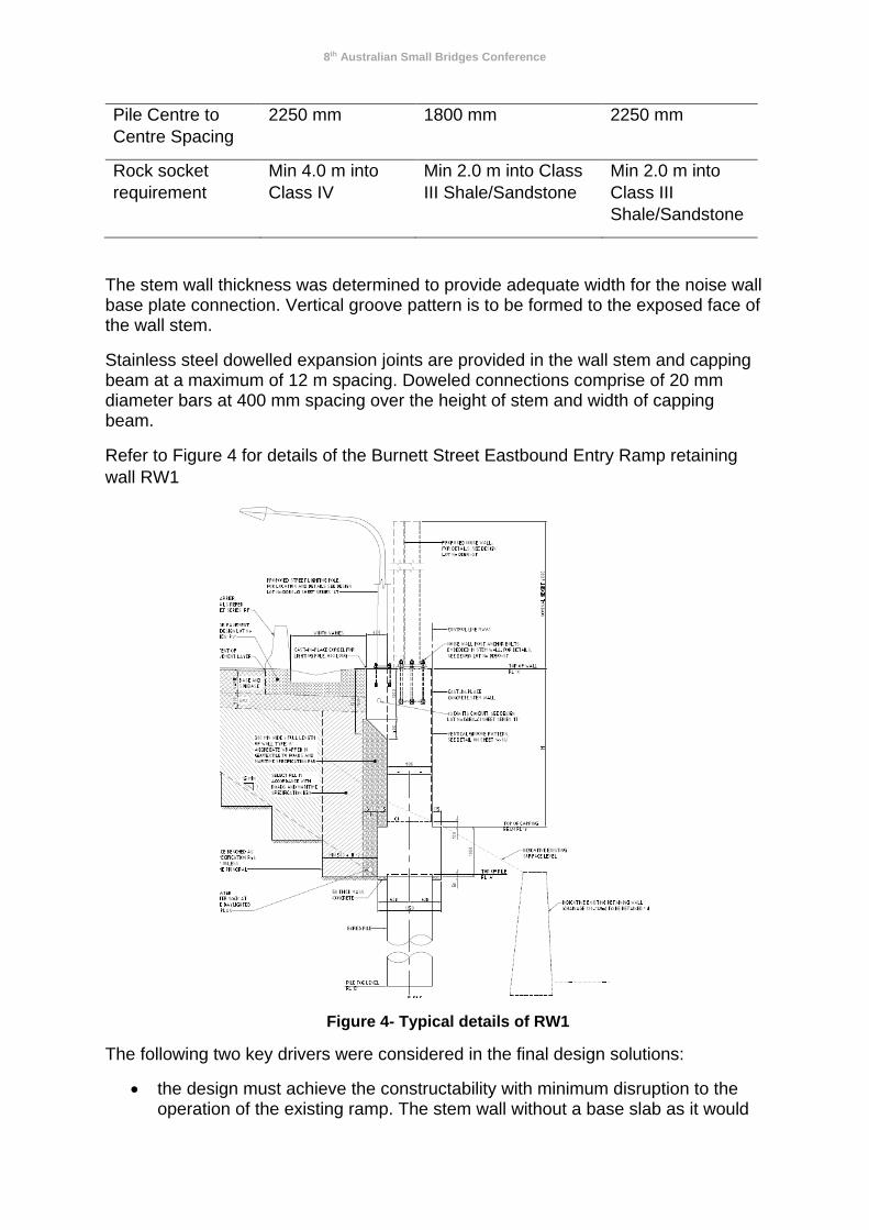
The stem wall thickness was determined to provide adequate width for the noise wall base plate connection. Vertical groove pattern is to be formed to the exposed face of the wall stem.
Stainless steel dowelled expansion joints are provided in the wall stem and capping beam at a maximum of 12 m spacing. Doweled connections comprise of 20 mm diameter bars at 400 mm spacing over the height of stem and width of capping beam.
Refer to Figure 4 for details of the Burnett Street Eastbound Entry Ramp retaining
wall RW1
Figure 4- Typical details of RW1
The following two key drivers were considered in the final design solutions:
• the design must achieve the constructability with minimum disruption to the operation of the existing ramp. The stem wall without a base slab as it would
8th Australian Small Bridges Conference
normally be required in an L-shaped wall configuration minimises the extent of temporary excavation into the existing road embankment, therefore maintaining the ramp operation
• the design must not induce additional loadings on the existing retaining wall, which is of unknown conditions. The piled support utilises the geotechnical strength of the soil strata below the existing local street level i.e at the base of the existing retaining wall. All the resistance by the soil layer being supported by the existing wall is ignored, resulting a maximum effective soil retained height of 8.0m
4.1.5. Design Methodology
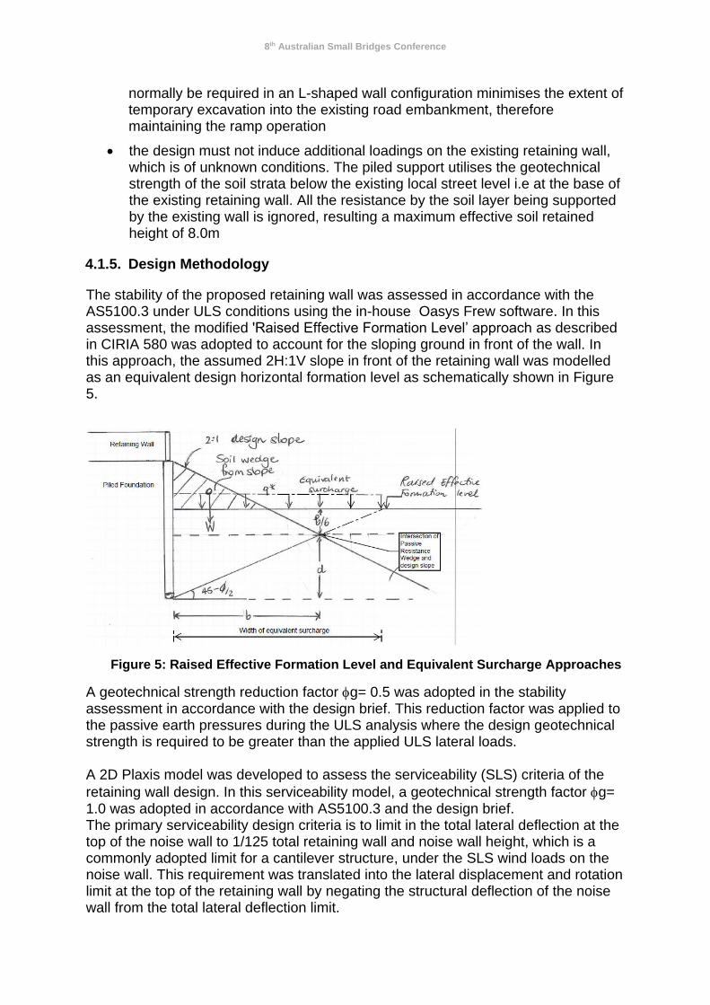
The stability of the proposed retaining wall was assessed in accordance with the AS5100.3 under ULS conditions using the in-house Oasys Frew software. In this assessment, the modified 'Raised Effective Formation Level’ approach as described in CIRIA 580 was adopted to account for the sloping ground in front of the wall. In this approach, the assumed 2H:1V slope in front of the retaining wall was modelled as an equivalent design horizontal formation level as schematically shown in Figure 5.
Figure 5: Raised Effective Formation Level and Equivalent Surcharge Approaches
A geotechnical strength reduction factor g= 0.5 was adopted in the stability assessment in accordance with the design brief. This reduction factor was applied to the passive earth pressures during the ULS analysis where the design geotechnical strength is required to be greater than the applied ULS lateral loads. A 2D Plaxis model was developed to assess the serviceability (SLS) criteria of the
retaining wall design. In this serviceability model, a geotechnical strength factor g= 1.0 was adopted in accordance with AS5100.3 and the design brief. The primary serviceability design criteria is to limit in the total lateral deflection at the top of the noise wall to 1/125 total retaining wall and noise wall height, which is a commonly adopted limit for a cantilever structure, under the SLS wind loads on the noise wall. This requirement was translated into the lateral displacement and rotation limit at the top of the retaining wall by negating the structural deflection of the noise wall from the total lateral deflection limit.

8th Australian Small Bridges Conference
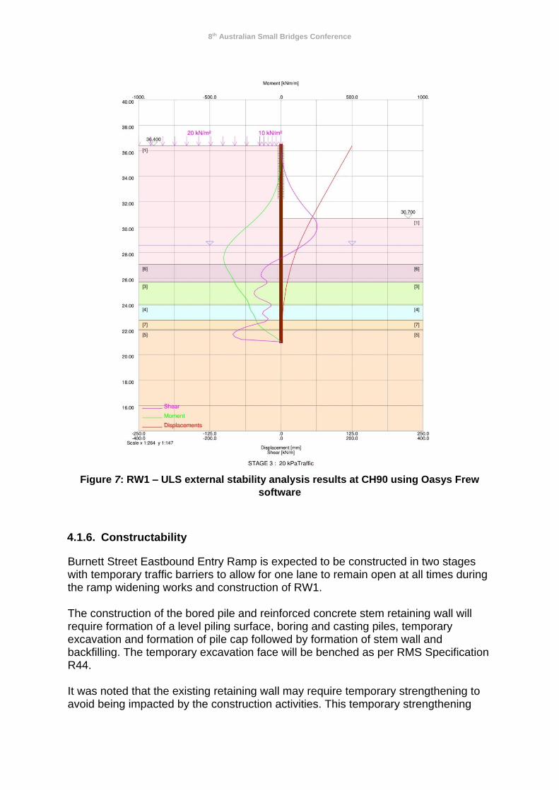
It was found that the serviceability design governed the overall pile design of the retaining wall. The design bending and shear actions for the structural design of the piles were obtained by applying an ULS load factor of 1.5 to the corresponding outputs from the serviceability model. The reinforcement was then determined accordingly.
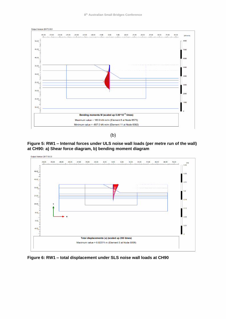
Selected PLAXIS and Frew outputs including bending moment and shear force
profiles and displacement contours are presented in Figures 5 to 7.
(a)
8th Australian Small Bridges Conference
(b)
Figure 5: RW1 – Internal forces under ULS noise wall loads (per metre run of the wall)
at CH90: a) Shear force diagram, b) bending moment diagram
Figure 6: RW1 – total displacement under SLS noise wall loads at CH90
8th Australian Small Bridges Conference
Figure 7: RW1 – ULS external stability analysis results at CH90 using Oasys Frew
software
4.1.6. Constructability
Burnett Street Eastbound Entry Ramp is expected to be constructed in two stages with temporary traffic barriers to allow for one lane to remain open at all times during the ramp widening works and construction of RW1. The construction of the bored pile and reinforced concrete stem retaining wall will require formation of a level piling surface, boring and casting piles, temporary excavation and formation of pile cap followed by formation of stem wall and backfilling. The temporary excavation face will be benched as per RMS Specification R44. It was noted that the existing retaining wall may require temporary strengthening to avoid being impacted by the construction activities. This temporary strengthening
8th Australian Small Bridges Conference
could be achieved by constructing a temporary batter in the wide nature strip in front of the existing wall. However, it is the contractor’s responsibility to determine an appropriate construction methodology and/or with temporary support as required to achieve the project requirements. The construction sequence for the retaining wall is expected as follows:
1. Prepare a level platform for the piles 2. Install the piles 3. Construct the pile capping beam 4. Construct the stem with noise wall anchor bolts cast into stem 5. Install wall drainage
6. Backfill behind the wall with select granular fill to within 1000mm of the top of the wall
4.2. CASE STUDY 2: RETAINING WALL RW2- COLEMAN STREET EASTBOUND ENTRY RETAINING WALL
The Coleman Street eastbound entry ramp is proposed to be widened to accommodate a new maintenance bay for a proposed gantry structure. The widening of the ramp involves a cutting up to 9 m high into the existing slope along the ramp. It must be noted that the concept design had proposed a free cantilever piled wall for the site. After a careful review of the concept design proposal, the soil nail wall solution was adopted at the detailed design phase due to its relatively lower construction costs.
4.2.1. Existing Site Constraints
The primary constraint at this site is that the design must achieve constructability while maintaining the operation of the existing eastbound entry ramp. In addition, due to the retained height of the wall, the retaining structure was considered to be a highly imposing landscape feature on the motorway. It was therefore critical that careful considerations were given to the urban design details on the structure.
4.2.2. Geotechnical Subsurface Conditions
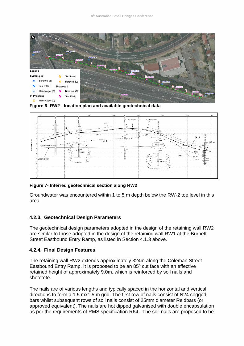
The ground conditions encountered along the proposed alignment of retaining wall RW2 include variable amounts of fill underlain by a relatively shallow residual soil profile that grades into Bringelly Shale and Minchinbury Sandstone rock units. Fill and residual soil layers were encountered in test locations up to 3.6 m depth below ground level. The soil profile is thickest at each end of the proposed alignment and becomes shallower towards mid-section of the wall. It was expected that the cutting would be primarily in rock with a relatively shallow soil profile along the crest. The rock class was expected to vary between Class V and Class II/I Shale. The location plan and a geotechnical long section at RW2 are presented in Figure 6 and Figure 7, respectively.
8th Australian Small Bridges Conference
Figure 6- RW2 - location plan and available geotechnical data
Figure 7- Inferred geotechnical section along RW2
Groundwater was encountered within 1 to 5 m depth below the RW-2 toe level in this area.
4.2.3. Geotechnical Design Parameters
The geotechnical design parameters adopted in the design of the retaining wall RW2 are similar to those adopted in the design of the retaining wall RW1 at the Burnett Street Eastbound Entry Ramp, as listed in Section 4.1.3 above.
4.2.4. Final Design Features
The retaining wall RW2 extends approximately 324m along the Coleman Street Eastbound Entry Ramp. It is proposed to be an 85o cut face with an effective retained height of approximately 9.0m, which is reinforced by soil nails and shotcrete. The nails are of various lengths and typically spaced in the horizontal and vertical directions to form a 1.5 mx1.5 m grid. The first row of nails consist of N24 cogged bars whilst subsequent rows of soil nails consist of 25mm diameter Reidbars (or approved equivalent). The nails are hot dipped galvanised with double encapsulation as per the requirements of RMS specification R64. The soil nails are proposed to be
8th Australian Small Bridges Conference
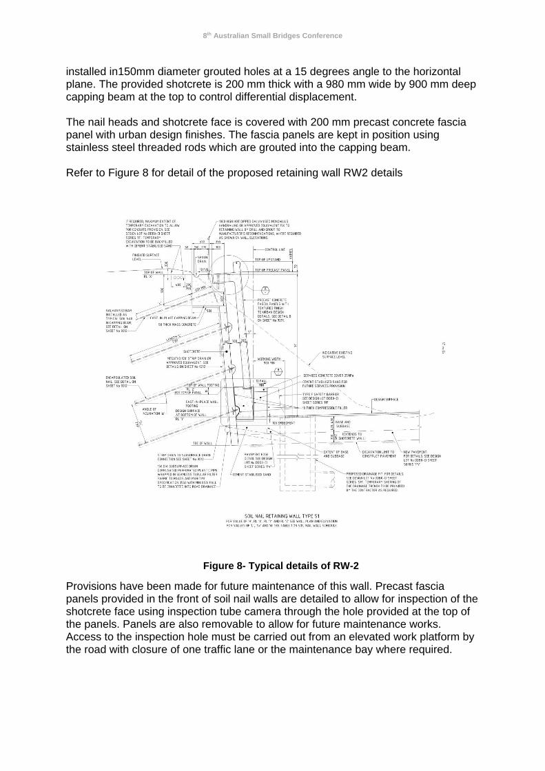
installed in150mm diameter grouted holes at a 15 degrees angle to the horizontal plane. The provided shotcrete is 200 mm thick with a 980 mm wide by 900 mm deep capping beam at the top to control differential displacement. The nail heads and shotcrete face is covered with 200 mm precast concrete fascia panel with urban design finishes. The fascia panels are kept in position using stainless steel threaded rods which are grouted into the capping beam. Refer to Figure 8 for detail of the proposed retaining wall RW2 details
Figure 8- Typical details of RW-2
Provisions have been made for future maintenance of this wall. Precast fascia panels provided in the front of soil nail walls are detailed to allow for inspection of the shotcrete face using inspection tube camera through the hole provided at the top of the panels. Panels are also removable to allow for future maintenance works. Access to the inspection hole must be carried out from an elevated work platform by the road with closure of one traffic lane or the maintenance bay where required.
8th Australian Small Bridges Conference
4.2.5. Design Methodology
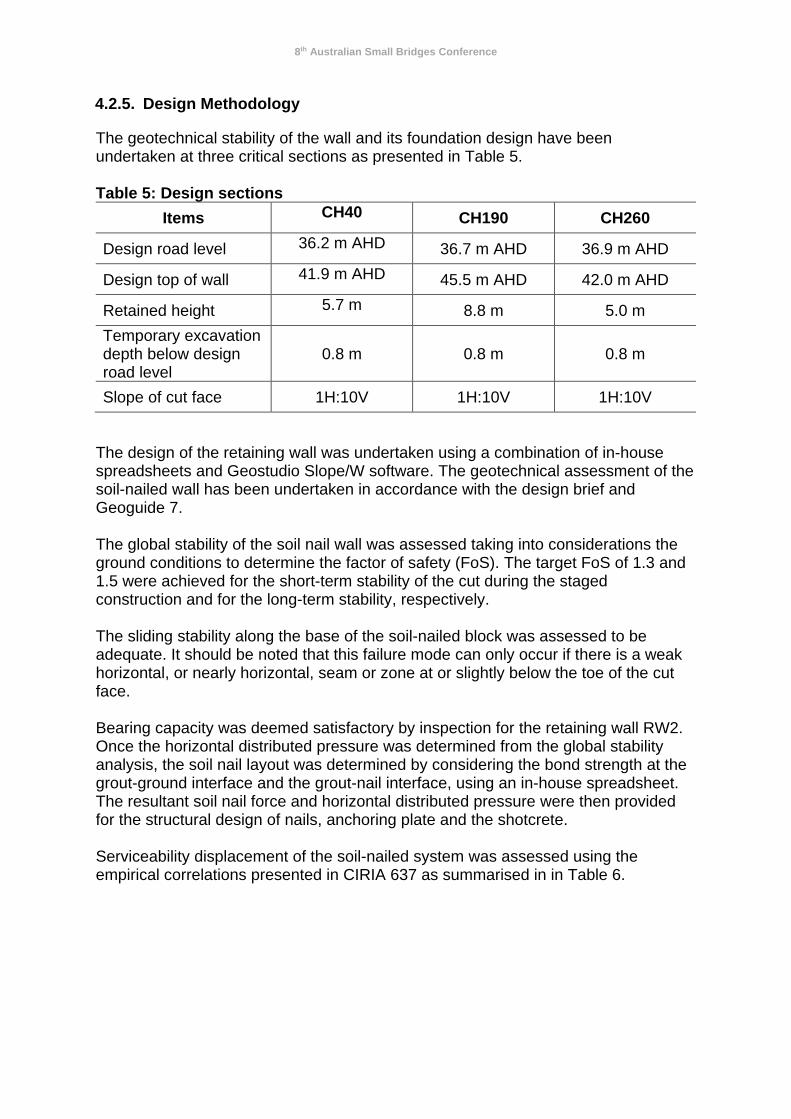
The geotechnical stability of the wall and its foundation design have been undertaken at three critical sections as presented in Table 5. Table 5: Design sections
Items CH40 CH190 CH260
Design road level 36.2 m AHD 36.7 m AHD 36.9 m AHD
Design top of wall 41.9 m AHD 45.5 m AHD 42.0 m AHD
Retained height 5.7 m 8.8 m 5.0 m
Temporary excavation depth below design road level
0.8 m 0.8 m 0.8 m
Slope of cut face 1H:10V 1H:10V 1H:10V
The design of the retaining wall was undertaken using a combination of in-house spreadsheets and Geostudio Slope/W software. The geotechnical assessment of the soil-nailed wall has been undertaken in accordance with the design brief and Geoguide 7. The global stability of the soil nail wall was assessed taking into considerations the ground conditions to determine the factor of safety (FoS). The target FoS of 1.3 and 1.5 were achieved for the short-term stability of the cut during the staged construction and for the long-term stability, respectively. The sliding stability along the base of the soil-nailed block was assessed to be adequate. It should be noted that this failure mode can only occur if there is a weak horizontal, or nearly horizontal, seam or zone at or slightly below the toe of the cut face. Bearing capacity was deemed satisfactory by inspection for the retaining wall RW2. Once the horizontal distributed pressure was determined from the global stability analysis, the soil nail layout was determined by considering the bond strength at the grout-ground interface and the grout-nail interface, using an in-house spreadsheet. The resultant soil nail force and horizontal distributed pressure were then provided for the structural design of nails, anchoring plate and the shotcrete. Serviceability displacement of the soil-nailed system was assessed using the empirical correlations presented in CIRIA 637 as summarised in in Table 6.
8th Australian Small Bridges Conference
Table 6: Anticipated displacements at the top of steep soil nail walls
Empirical correlations
Soil type
Weathered rock/Stiff soils
Sandy Soils Clayey Soils
Δx=Δy(1) H/1000 (2) 2H/1000 3H/1000
Coefficient(3) (k) 0.8 1.25 1.50 Notes: 1. Δx and Δy are horizontal and vertical displacements at top of wall, respectively.
2. H is retained height. 3. Horizontal displacement behind soil-nailed block is estimated as Δ0=k(1-tanφ’).H
The geotechnical strength of the soil nails were calculated as the ultimate strength
(Ru) multiplied by an importance category reduction factor (n) given in Table 12.3.3(A) of AS 5100.3. An importance category reduction factor of 0.7 has been adopted for this analysis. Testing of the soil nails will be carried out in accordance with the requirements of RMS specification R64.
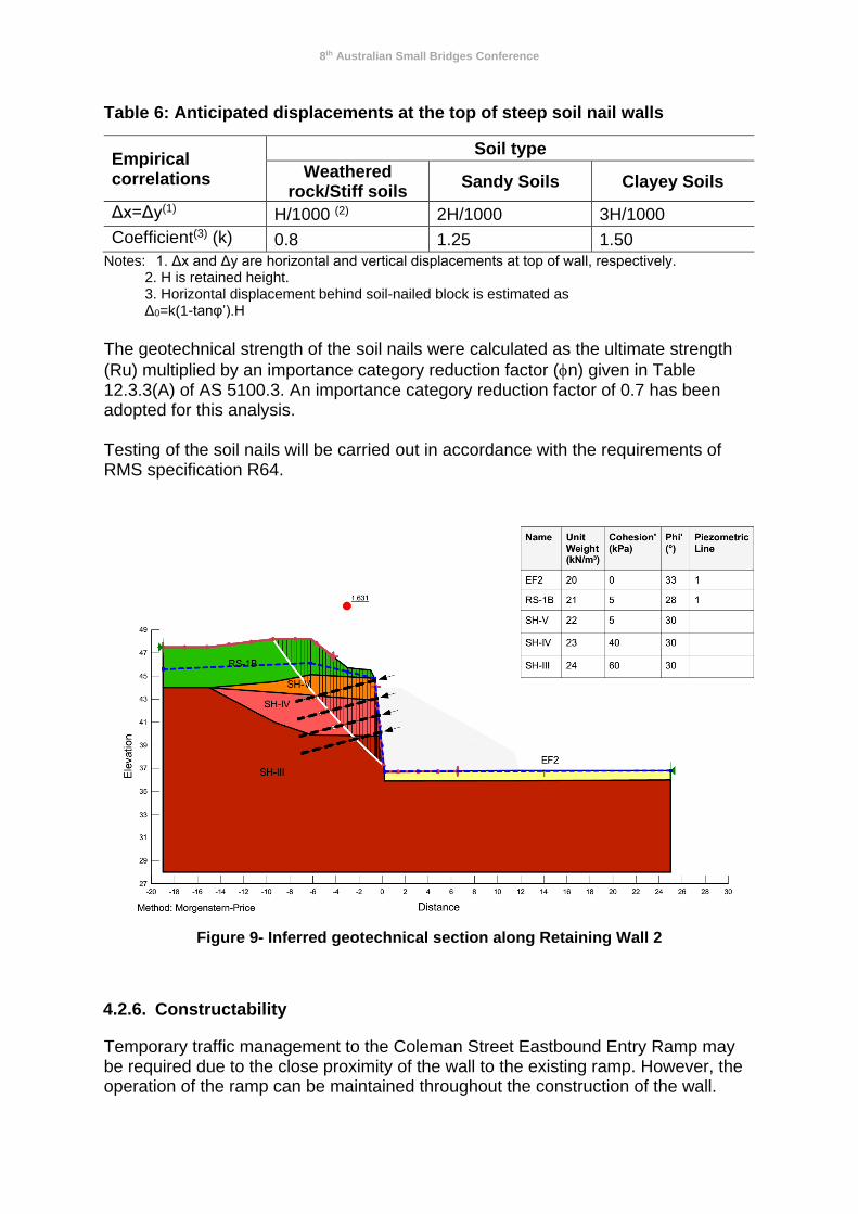
Figure 9- Inferred geotechnical section along Retaining Wall 2
4.2.6. Constructability
Temporary traffic management to the Coleman Street Eastbound Entry Ramp may be required due to the close proximity of the wall to the existing ramp. However, the operation of the ramp can be maintained throughout the construction of the wall.
8th Australian Small Bridges Conference
The wall construction should follow the typical construction sequence below:
1. Construct working platform as required in front of existing batter. 2. Commence excavation to the face of cut. 3. Install first row soil nails (including sacrificial suitability test nails, if applicable) 4. Undertake suitability and acceptability nail tests, as required. 5. Construct capping beam and spoon drain. 6. Fix strip drains to the face of the excavation. 7. Commence installation of steel mesh and apply shotcrete facing to the
excavation. 8. Repeat Steps 3 to 8 (except 5) to the cut floor (as required). 9. Install handrails and conduits. 10. Install and connect subsurface drainage to longitudinal road drainage system. 11. Backfill with select granular fill to the design surface level. 12. Install footing reinforcement and formwork and pour concrete footing. 13. Place precast panel unit and fix to top of the capping beam using connection
dowels. Grout panel and footing connections.
4.3. CASE STUDY 3: RETAINING WALL RW3 - M7 EASTBOUND ENTRY RAMP
The retaining wall RW3 has been proposed to enable the widening of M7 eastbound on ramp embankment to accommodate a maintenance bay. The wall is approximately 100 m in length with a retained height of about 3.0 m. The overall height of the ramp embankment is approximately 12 m with 2H:1V batter slopes.
4.3.1. Existing Site Constraints
The primary constraint at this site is the design must achieve constructability while maintaining the operation of the existing eastbound entry ramp. In addition, due to the height of the existing M7 eastbound ramp embankment, the retaining structure design must not impact on the overall stability of the existing slope.
4.3.2. Geotechnical Subsurface Conditions
The subsurface ground condition at the RW3 location is anticipated to consist a thick layer of engineered fill associated with the M7 ramp construction circa 2004. Below the embankment, the existing fill is expected to comprise stiff or medium dense mixture of gravel, sand and clay. Shale bedrock is anticipated to be encountered at over 20 m depth below the road design level as suggested by available boreholes.
4.3.3. Geotechnical Design Parameters
The geotechnical design parameters adopted in the design of the retaining wall RW2 are similar to those adopted in the design of the retaining wall RW1 at the Burnett Street Eastbound Entry Ramp, as listed in Section 4.1.3 above.
8th Australian Small Bridges Conference
4.3.4. Final Design Features
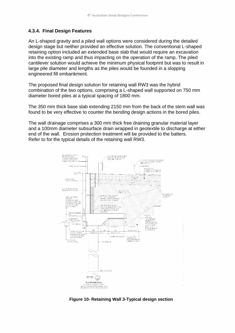
An L-shaped gravity and a piled wall options were considered during the detailed design stage but neither provided an effective solution. The conventional L-shaped retaining option included an extended base slab that would require an excavation into the existing ramp and thus impacting on the operation of the ramp. The piled cantilever solution would achieve the minimum physical footprint but was to result in large pile diameter and lengths as the piles would be founded in a slopping engineered fill embankment. The proposed final design solution for retaining wall RW3 was the hybrid combination of the two options, comprising a L-shaped wall supported on 750 mm diameter bored piles at a typical spacing of 1800 mm. The 350 mm thick base slab extending 2150 mm from the back of the stem wall was found to be very effective to counter the bending design actions in the bored piles. The wall drainage comprises a 300 mm thick free draining granular material layer and a 100mm diameter subsurface drain wrapped in geotextile to discharge at either end of the wall. Erosion protection treatment will be provided to the batters. Refer to for the typical details of the retaining wall RW3.
Figure 10- Retaining Wall 3-Typical design section

8th Australian Small Bridges Conference
4.3.5. Design Methodology
The minimum pile length and spacing were confirmed to achieve the minimum FoS for global stability. The serviceability displacement requirements and internal forces within the wall and piles were also assessed using finite element 2D PLAXIS and Frew, respectively.
Selected PLAXIS outputs are presented in Figure 11 and Figure 12.
Figure 11: Retaining Wall 3 – total lateral displacement contours under SLS traffic
loads at CH30
4.3.6. Constructability
The M7 eastbound entry ramp will be constructed in one stage with temporary traffic barriers to allow one lane to remain open at all times during the ramp widening works and retaining wall construction. The following construction sequence is required to construct the L-shaped wall with piled foundations:
1. Excavate temporary batter and prepare a level piling platform 2. Install the piles 3. Construct the pile capping beam 4. Construct the base and stem 5. Install wall drainage 6. Backfill behind the wall with select granular fill to within 1000mm of the top of
the wall 7. Complete the pavement 8. Install the handrail

8th Australian Small Bridges Conference
(a)
(b) Figure 12: Retaining Wall 3 – Internal forces under ULS noise wall loads (per metre
run of the wall) at CH90: a) Shear force diagram, b) bending moment diagram
8th Australian Small Bridges Conference
5. CONCLUSION
The general design constraints and criteria for the retaining wall structures on the M4
Smart Motorway Project in Sydney have been presented in this paper. Specific
design challenges and the final design solutions at the Burnett Street Eastbound
Entry Ramp, Coleman Street Eastbound Entry Ramp and the M7 Eastbound Entry
Ramp have also been provided herewith.
The overarching challenge to the design of the retaining walls on the project is to find
design solutions that can be constructed with minimum disruptions to the operation
of the existing road network, including the mainline motorway, and the surrounding
communities. This challenge, in context of each individual retaining wall site,
translated into the design requirements that were unique for the individual sites. As
such, bespoke design solution which best met the site-specific requirements was
developed.
REFERENCES
• CIRIA C637, Soil Nailing – best practice guidance, 2005.
• CIRIA C580, Embedded retaining walls – guidance for economic design, Gaba
AR, Simpson B, Powrie W, Beadman DR, 2003.
• Geoguide 7, Guide to Soil Nail Design and Construction, The Government of
Hong Kong Special Administrative Region, March 2008.
• Pells, P., Mostyn, G. and Walker, F, Foundations on Sandstone and Shale in
Sydney Region. Australian Geomechanics, pg. 17-29, Dec. 1998.
• Road and Maritime Services QA Specification R44 – Earthworks.
• Road and Maritime Services, Excavation adjacent to RMS infrastructure,
Geotechnical Technical Direction (GTD 2012/001), 27 April 2012.
• Roads and Maritime Services QA Specification B30 -Excavation and Backfill for
Bridgeworks.
• Roads and Maritime Services QA Specification B59 – Bored Cast-in-Place
Reinforced Concrete Piles (without permanent casing).
• Standards Australia AS 5100.3-2004, Bridge design - Foundations and soil
supporting structures.
• Standards Australia AS 2159-2009, Piling – Design and Installation.
• Standards Australia AS 1170.4-1993, Structural design actions – earthquake
actions in Australia.
ACKNOWLEDGEMENTS
The authors would like to acknowledge and thank the NSW Roads and Maritime
Services for their permissions to use the M4SM retaining walls as case studies for

8th Australian Small Bridges Conference
this paper. The authors also would like to acknowledge the colleagues from Arup
and Amey who have contributed to the design development of this M4SM project.
AUTHOR BIOGRAPHIES
Kenny Luu is a principal civil engineer and a bridge team leader with Amey Ausralia.
He has over 16 years of combined research and industry experience with a strong
focus in the concept and detailed design of bridges, earth retaining structures and
other civil structures. On the M4 Smart Motorway project, Kenny was the discipline
leader for bridges and structures.
Saman Zargarbashi is a lead senior geotechnical engineer with Arup. He has over
15 years experience in civil and geotechnical engineering including engineering
design, project managements, site investigations, construction supervision and
research. His consulting assignments have included tender and construction phase
design of large scale transport, mining and civil infrastructure projects and urban
developments across Australia and overseas. On the M4 Smart Motorway project,
Saman was the discipline leader for geotechnics.