Design of Tension Members Structural Elements Subjected to Axial Tensile Forces Cables in Suspension...
49
Design of Tension Members Structural Elements Subjected to Axial Tensile Forces ables in Suspension and Cable-Stayed Bridges Trusses Bracing for Buildings and Bridges
-
Upload
camilla-douglas -
Category
Documents
-
view
224 -
download
4
Transcript of Design of Tension Members Structural Elements Subjected to Axial Tensile Forces Cables in Suspension...

Design of Tension Members
Structural Elements Subjected to Axial Tensile Forces
Cables in Suspension and Cable-Stayed Bridges
Trusses
Bracing for Buildings and Bridges

LAST TIME
• Design of Tension Members
• Tables for the Design
• Threaded Rods and Cables

Design of Tension Members
• Objective– Find a member with adequate gross and net areas– Find a member that satisfies L/r<300
• Does not apply to cables and rods
Required StrengthAvailable Strength(Nominal Resistance)
eu AF75.0gy AF9.0
LRFD minLD 6.12.1 D4.1
LRFD max

Design of Tension Members
Determine required Area
To prevent yielding y
uggyu F
PAAFP
9.090.0
To avoid fracture y
ueeuu F
PAAFP
75.075.0
Yielding controls if eugy AFAF 75.090.0
u
y
g
e
F
F
A
A2.1

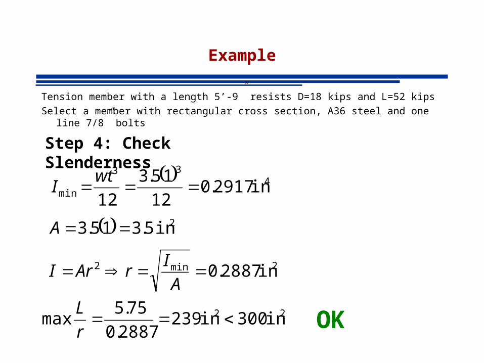
Example
Tension member with a length 5’-9” resists D=18 kips and L=52 kips
Select a member with rectangular cross section, A36 steel and one line 7/8” bolts
kips
kipsLD
kipsDPu 8.104
8.104526.1182.16.12.1
2.25184.14.1max
Step 1: Required Strength
2
, 235.3369.0
8.104in
F
PA
yt
ureqg
Step 2: Required Areas
2
, 409.25875.0
8.104in
F
PA
ut
ureqe

Example
Tension member with a length 5’-9” resists D=18 kips and L=52 kips
Select a member with rectangular cross section, A36 steel and one line 7/8” bolts
Step 3: Plate Selection based on Ag
inwwinA reqreqreqg 235.3)1(235.3 2,
Try thickness t = 1 in
Choose PL 1 X 3-1/2See Manual pp1-8 for availability of plate products

Example
Tension member with a length 5’-9” resists D=18 kips and L=52 kips
Select a member with rectangular cross section, A36 steel and one line 7/8” bolts
Step 4: Check Effective Area
409.25.28
1
8
75.3x11
1
,2
reqe
holegne
Ain
AAUAAOK
Example
Tension member with a length 5’-9” resists D=18 kips and L=52 kips
Select a member with rectangular cross section, A36 steel and one line 7/8” bolts
Step 4: Check Slenderness
433
min in 2917.012
15.3
12
wtI
2in 5.315.3 A
2min2 in 2887.0A
IrArI
22 in 300in 2392887.0
75.5max
r
LOK
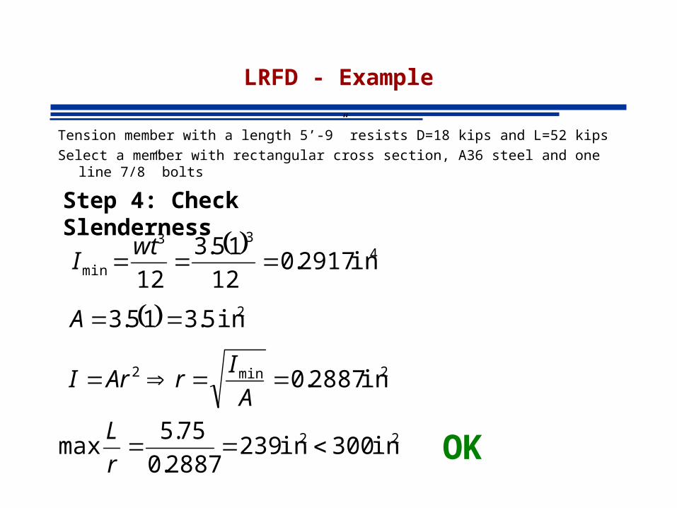
LRFD - Example
Tension member with a length 5’-9” resists D=18 kips and L=52 kips
Select a member with rectangular cross section, A36 steel and one line 7/8” bolts
Step 4: Check Slenderness
433
min in 2917.012
15.3
12
wtI
2in 5.315.3 A
2min2 in 2887.0A
IrArI
22 in 300in 2392887.0
75.5max
r
LOK
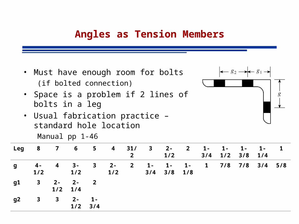
Angles as Tension Members
• Must have enough room for bolts (if bolted connection)
• Space is a problem if 2 lines of bolts in a leg
• Usual fabrication practice – standard hole locationManual pp 1-46
Leg 8 7 6 5 4 31/2 3 2-1/2 2 1-3/4 1-1/2 1-3/8 1-1/4 1
g 4-1/2 4 3-1/2 3 2-1/2 2 1-3/4 1-3/8 1-1/8 1 7/8 7/8 3/4 5/8
g1 3 2-1/2 2-1/4 2
g2 3 3 2-1/2 1-3/4

Example
• Select and unequal-leg angle tension member 15 feet long to resist a service dead load of 35 kips and a service live load of 70 kips. Use A36

Angle - Example
kips
kipsLD
kipsDPu 154
154706.1352.16.12.1
49354.1max
Step 1: Required Strength
2
, 75.4369.0
154
9.0in
F
PA
y
ureqg
Step 2: Required Areas
2
, 54.3585.0
154
75.0in
F
PA
u
ureqe
inL
ru
req 6.0300
)12(15
300

Angle - Example
Step 3: Angle Selection based on Ag
Two lines of bolts, therefore min. length of one leg = 5 insee table
Choose L6x4x1/2 A=4.75, rmin=0.864See Manual pp1-42
2
, 75.4369.0
154
9.0in
F
PA
y
ureqg

Angle - Example
Step 4: Check Effective Area
54.329.3875.385.0 ,2 reqene AinUAA NG
Length of connection not known4 – bolts in direction of load U=0.85
2875.32
1
8
1
4
3275.4 inAAA holegn
Angle - Example
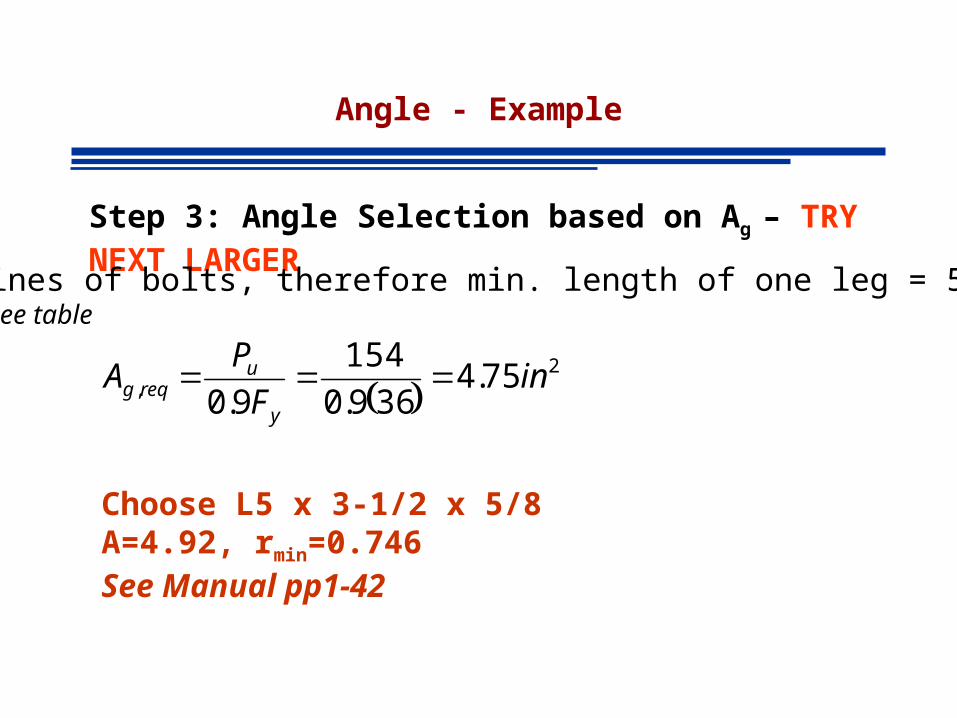
Step 3: Angle Selection based on Ag – TRY NEXT LARGER
Two lines of bolts, therefore min. length of one leg = 5 insee table
Choose L5 x 3-1/2 x 5/8 A=4.92, rmin=0.746See Manual pp1-42
2
, 75.4369.0
154
9.0in
F
PA
y
ureqg

Angle - Example
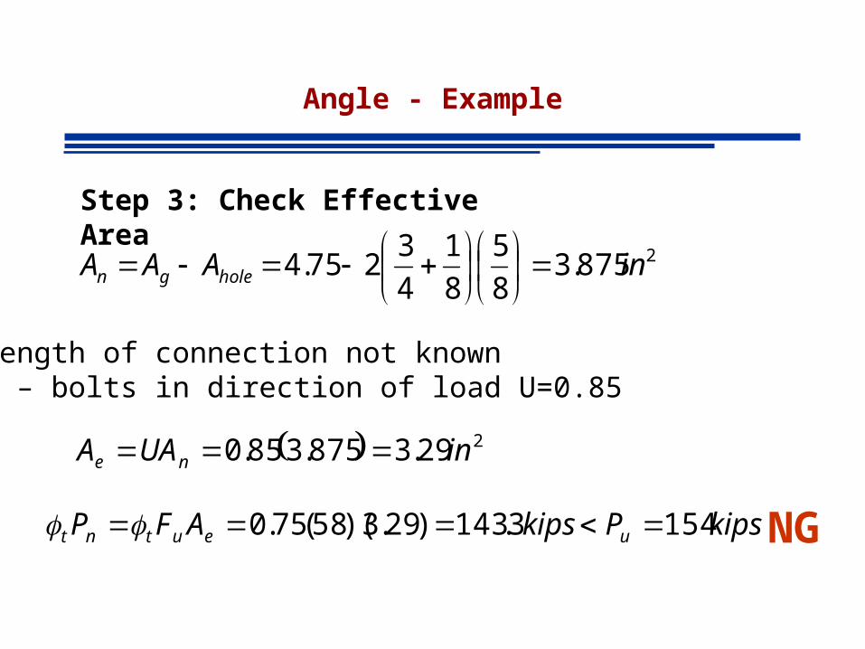
Step 4: Check Effective Area
54.3252.3826.385.0 ,2 reqene AinUAA NG
Length of connection not known4 – bolts in direction of load U=0.8
2826.38
5
8
1
4
3292.4 inAAA holegn

Angle - Example
Step 3: Angle Selection based on Ag – TRY NEXT LARGER
Two lines of bolts, therefore min. length of one leg = 5 insee table
Choose L8 x 4 x 1/2 A=5.75, rmin=0.863See Manual pp1-42
2
, 75.4369.0
154
9.0in
F
PA
y
ureqg

Angle - Example
Step 4: Check Effective Area
54.314.4875.485.0 ,2 reqene AinUAA OK
Length of connection not known4 – bolts in direction of load U=0.8
2875.48
5
8
1
4
3275.5 inAAA holegn

TABLES FOR DESIGN OF TENSION MEMBERS

Example
• Select and unequal-leg angle tension member 15 feet long to resist a service dead load of 35 kips and a service live load of 70 kips. Use A36

Example – Using Tables
kips
kipsLD
kipsDPu 154
154706.1352.16.12.1
49354.1max
Step 1: Required Strength
Step 2: Choose L based on Pu
Choose L6x4x1/2 A=4.75, rmin=0.980
kipsPyielding nt 154 : kipsPrupture nt 155 :
See Manual pp 5-15
Angle - Example
Step 3: Check Effective Area
229.3875.385.0 inUAA ne
NG
Length of connection not known4 – bolts in direction of load U=0.85
2875.38
5
8
1
4
3275.4 inAAA holegn
kipsPkipsAFP ueutnt 1543.143)29.3)(58(75.0

Angle - Example
Shape did not work because table values are for Ae/Ag=0.75
In this problem Ae/Ag=3.29/4.75 = 0.693
Enter table with adjusted Pu as
uPratioactual
75.0

Example – Using Tables
Step 4: Choose L based on ADJUSTED Pu
Choose L8x4x1/2 A=5.75, rmin=0.863
kipsPyielding nt 186 : kipsPrupture nt 187 :
See Manual pp 5-14
kipsPu 16715469.0
75.0

Angle - Example
Step 5: Check Effective Area
214.4875.485.0 inUAA ne
OK
Length of connection not known4 – bolts in direction of load U=0.85
2875.42
1
8
1
4
3275.5 inAAA holegn
kipsPkipsAFP ueutnt 154180)14.4)(58(75.0
Tension Members in Roof Trusses
• Main supporting elements of roof systems where long spans are required
• Used when the cost and weight of a beam would be prohibitive
• Often used in industrial or mill buildings

Tension Members in Roof Trussed
PinHinge
Supporting walls: reinforced concrete, concrete block, brick or combination

Tension Members in Roof Trussed

Tension Members in Roof Trusses
Sag Rods are designed to provide lateral support to purlins and carry the component of the load parallel to the roof
Located at mid-point, third points, or more frequently
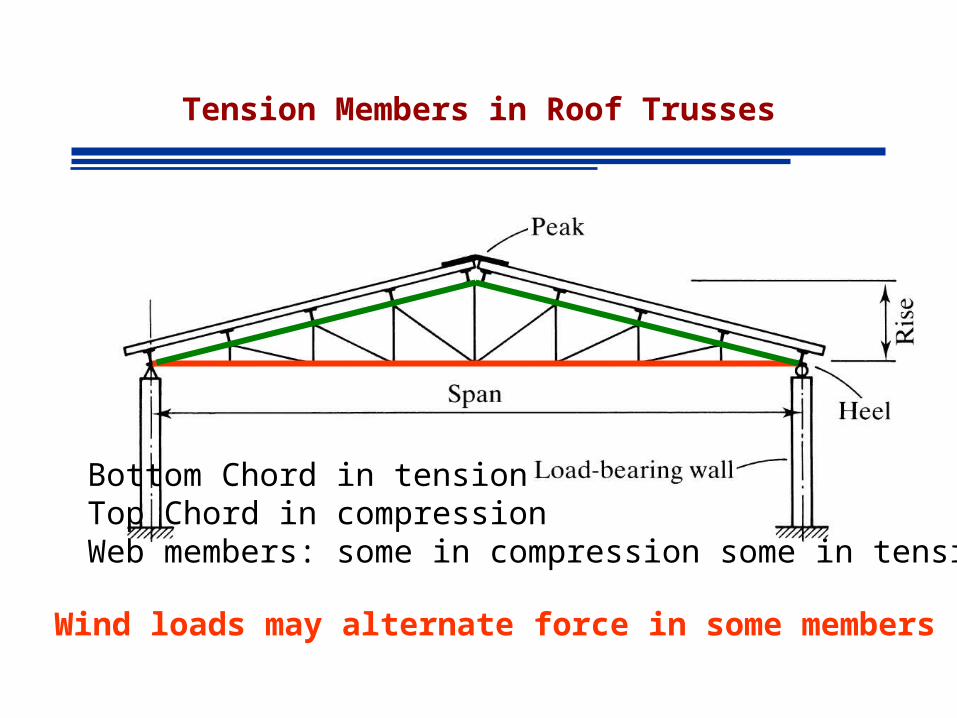
Tension Members in Roof Trusses
Bottom Chord in tensionTop Chord in compressionWeb members: some in compression some in tension
Wind loads may alternate force in some members

Tension Members in Roof Trusses
Chord Members are designed as continuous
Joint rigidity introduces small moments that are usually ignored
Bending caused by loads applied directly on members must be taken into account
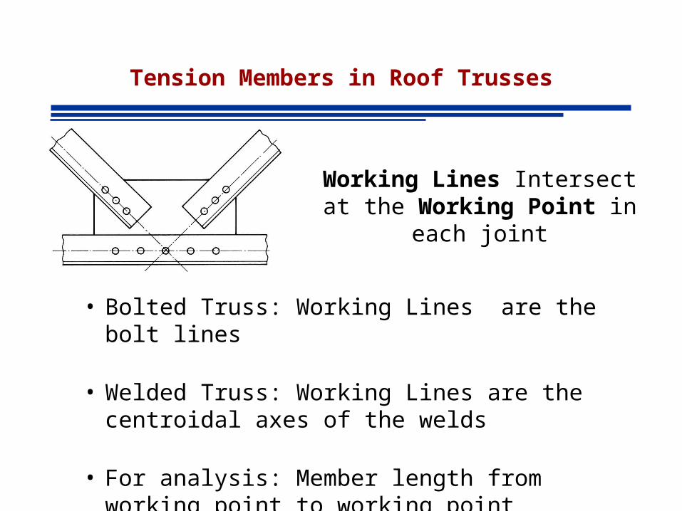
Tension Members in Roof Trusses
• Bolted Truss: Working Lines are the bolt lines
• Welded Truss: Working Lines are the centroidal axes of the welds
• For analysis: Member length from working point to working point
Working Lines Intersect at the Working Point in each joint

Tension Members in Roof Trusses
Bolted trusses
Double Angles for chords
Double Angles for web members
Single Gusset plate

Tension Members in Roof Trusses
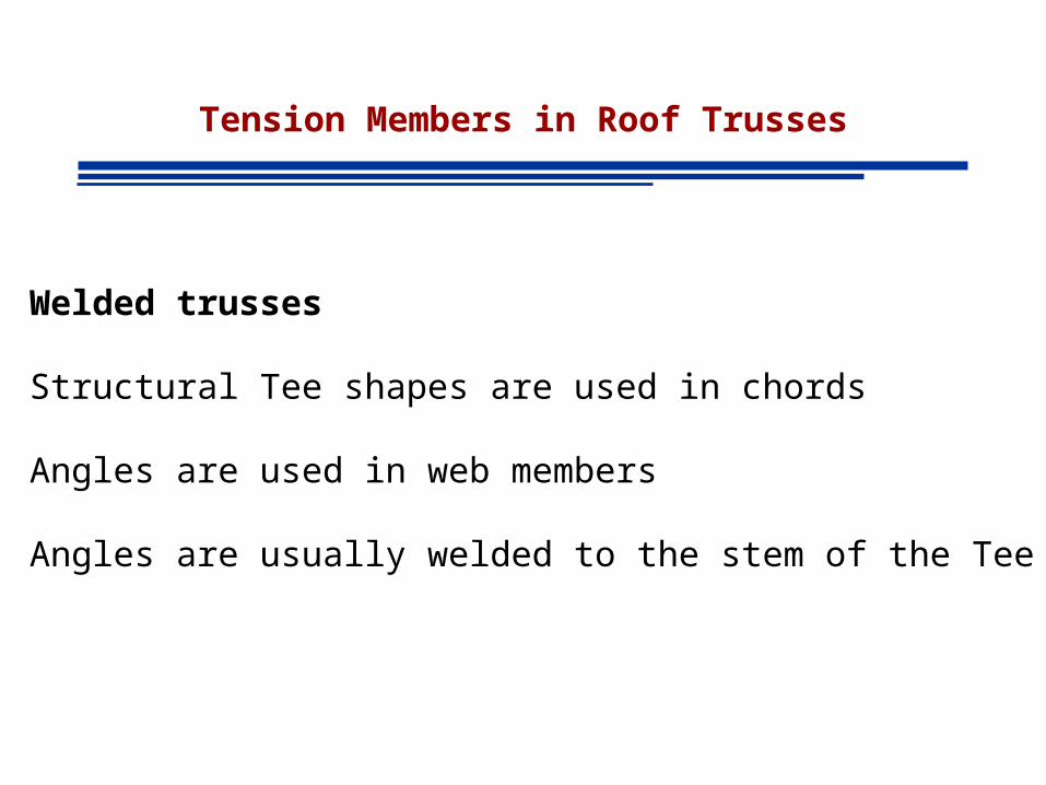
Welded trusses
Structural Tee shapes are used in chords
Angles are used in web members
Angles are usually welded to the stem of the Tee
Tension Members in Roof Trusses
Welded trusses
Structural Tee shapes are used in chords
Angles are used in web members
Angles are usually welded to the stem of the Tee

Example
Select a structural Tee for the bottom chord of the Warren roof truss. Trusses are welded and spaced at 20 feet. Assume bottom chord connection is made with 9-inch long longitudinal welds at the flange. Use A992 steel and the following load data (wind is not considered)
Purlins M8x6.5
Snow 20 psf horizontal projection
Metal Deck 2 psf
Roofing 4 psf
Insulation 3 psf

Step 1 – Load Analysis
DEAD (excluding purlins)Deck 2 psf
Roof 4 psf
Insulation 3 psf
Total 9 psf
Total Dead Load = 9(20) = 180 lb/ft
20ft
180(5)=900 lb
……
180(2.5)=450 lb

Step 1 – Load Analysis
PURLINS M8x6.5
Purlin Load = 6.5(20) = 130 lb 20ft
……
130 lb 130 lb
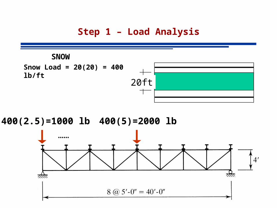
Step 1 – Load Analysis
SNOWSnow Load = 20(20) = 400 lb/ft
20ft
……
400(2.5)=1000 lb 400(5)=2000 lb

Step 1 – Load Analysis
Dead Load of TrussAssume 10% of all other loads
……
End Joint 0.1(9(20)(20)+130+1000)=158 lb
158 lb 303 lb
Interior Joint 0.1(900+130+2000)=303 lb

Step 1 – Load Analysis
……
450+130+158 = 738 lb 900+130+303 = 1333 lb
D
S
1000 lb 2000 lb
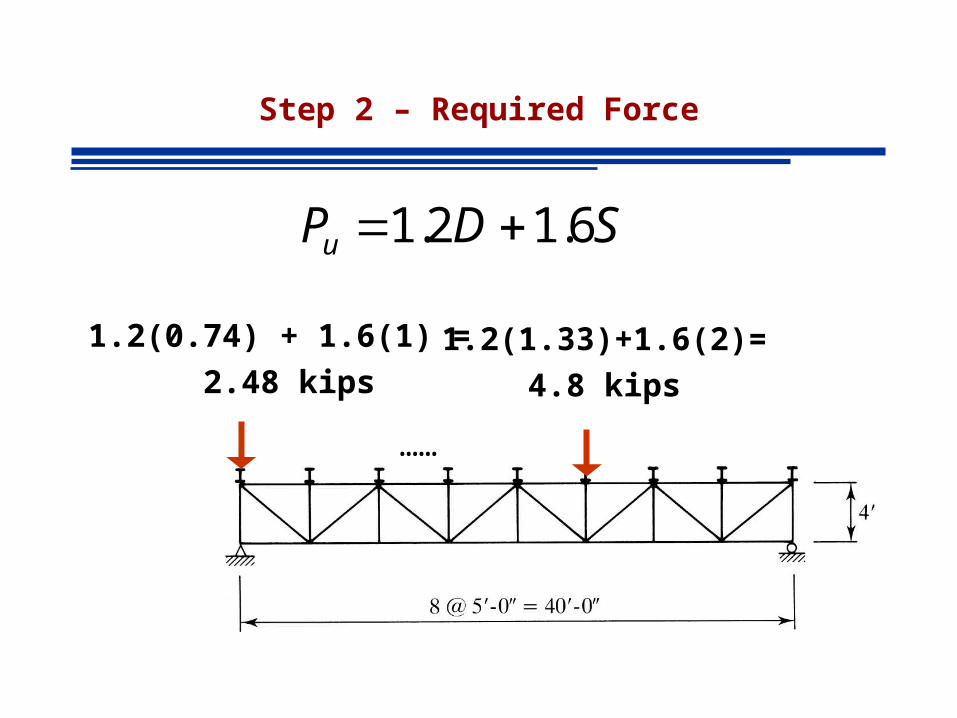
Step 2 – Required Force
……
1.2(0.74) + 1.6(1) =
2.48 kips1.2(1.33)+1.6(2)=
4.8 kips
SDPu 6.12.1

Step 2 – Required Force
Method of Sections
kips 04.480 IJE FM
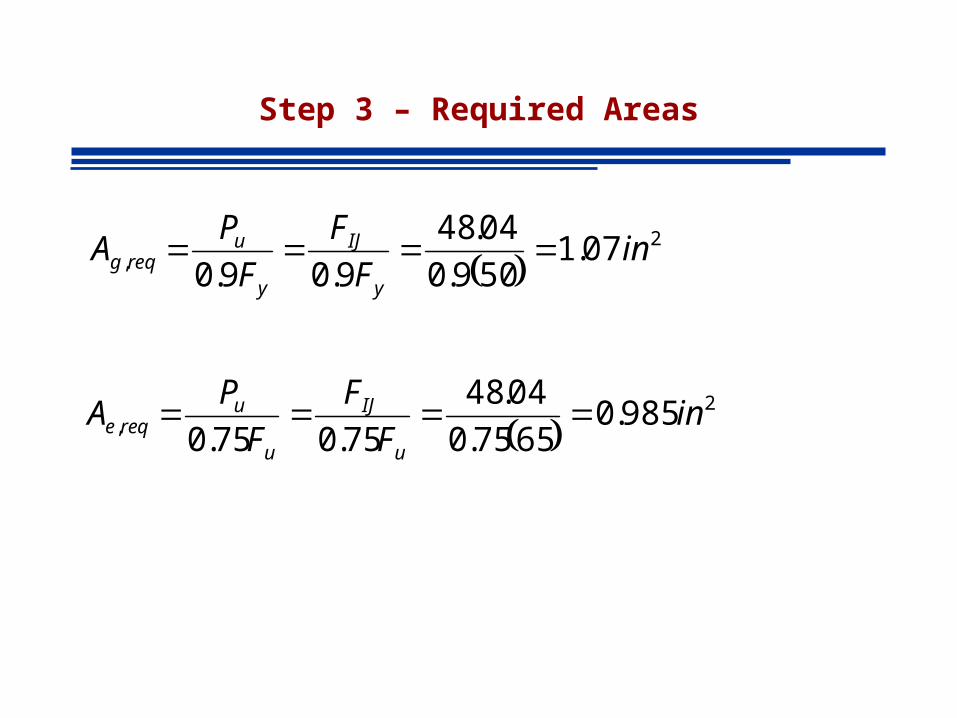
Step 3 – Required Areas
2
, 07.1509.0
04.48
9.09.0in
F
F
F
PA
y
IJ
y
ureqg
2
, 985.06575.0
04.48
75.075.0in
F
F
F
PA
u
IJ
u
ureqe

Step 4: T Selection based on Ag
Choose MT5x3.75 A=1.10 in2
See Manual pp1-68
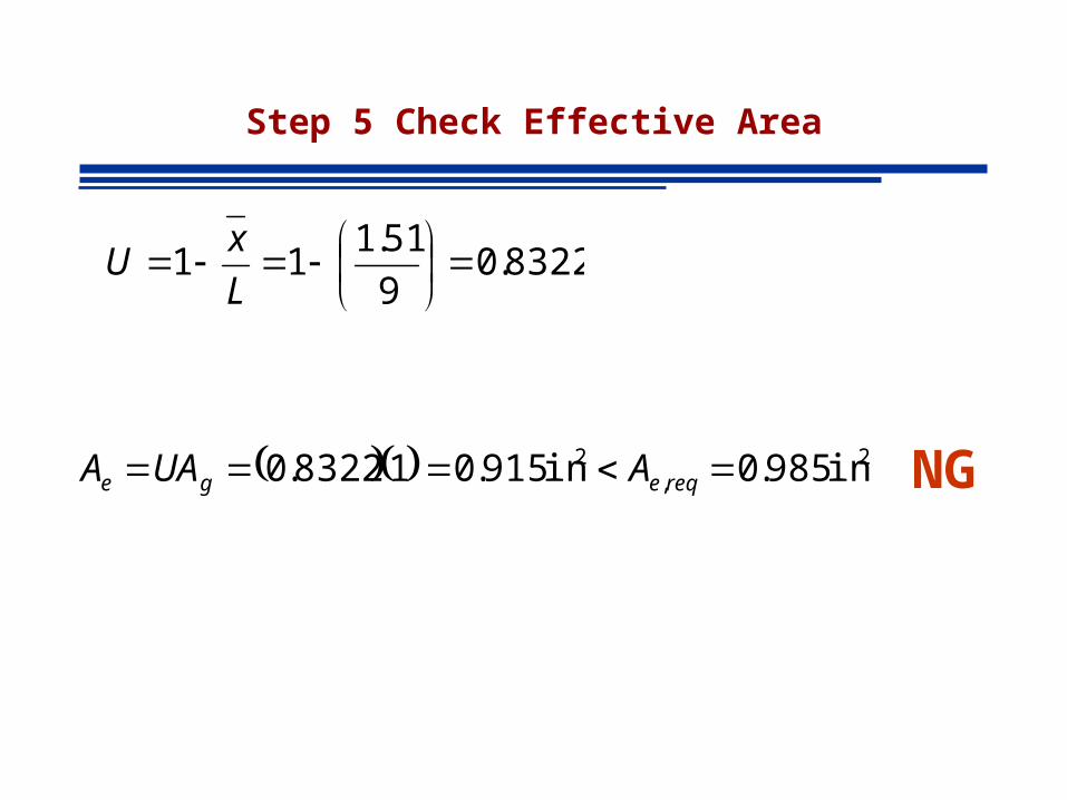
Step 5 Check Effective Area
2,
2 in 985.0in 915.018322.0 reqege AUAA NG
8322.09
51.111
L
xU

Step 6 TRY NEXT LARGER
Choose MT6X5 A=1.46 in2 See Manual pp1-68

Step 7 Check Effective Area
2,
2 in 985.0in 16.146.17933.0 reqege AUAA OK
7933.09
51.111
L
xU
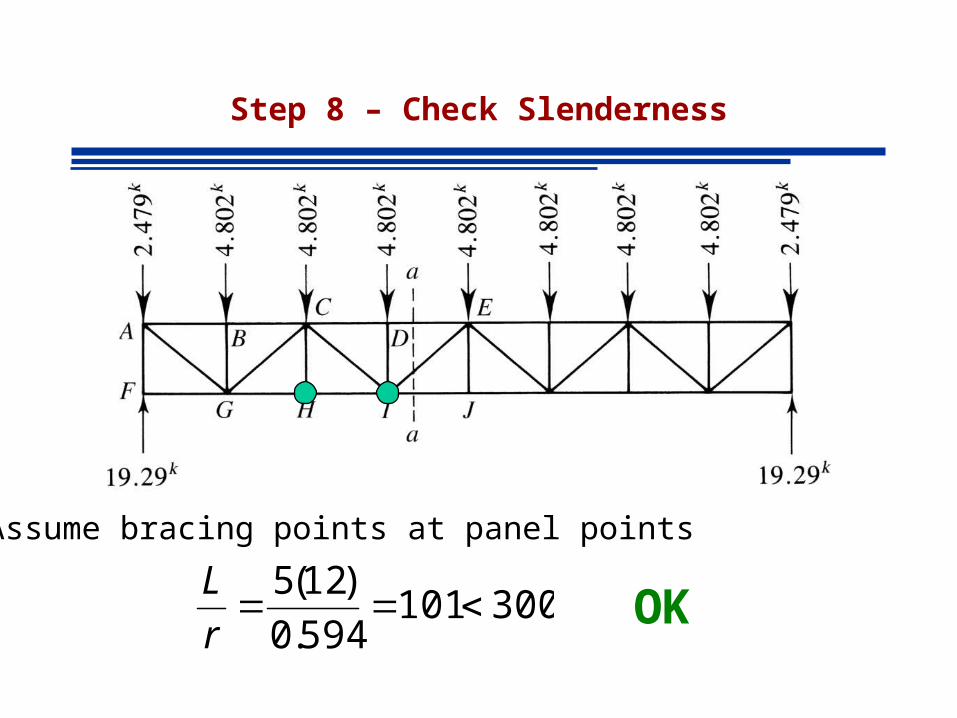
Step 8 – Check Slenderness
Assume bracing points at panel points
300101594.0
)12(5
r
LOK