Design of Smart Home Control System Based on Wireless ...
11
Research Article Design of Smart Home Control System Based on Wireless Voice Sensor Changchun Yang Shanxi Vocational & Technical College of Finance & Trade, Jingzhong, Shanxi 030031, China Correspondence should be addressed to Changchun Yang; [email protected] Received 22 September 2021; Accepted 4 October 2021; Published 26 October 2021 Academic Editor: Guolong Shi Copyright © 2021 Changchun Yang. This is an open access article distributed under the Creative Commons Attribution License, which permits unrestricted use, distribution, and reproduction in any medium, provided the original work is properly cited. With the rapid development of economy, science, and technology, people have higher and higher requirements for the quality of home life, and smart home systems are required to have higher convenience and comfort. The continuous development of embedded technology, short-range wireless communication technology, and microcontroller technology provides a new development direction for the research and development of smart home systems. Under the premise of fully studying the research status and development trend of smart home systems, this paper combines embedded technology, ZigBee wireless communication technology, voice recognition technology, GSM communication technology, etc., and proposes a ZigBee-based smart voice home appliance control system. The system adopts ZigBee wireless communication to form a comprehensive management system for household electrical appliances, electronic and electrical equipment, etc., for household electrical control, intelligent security, and environmental monitoring. This paper designs the overall scheme of a smart home control system based on voice recognition technology. According to this scheme, the hardware and software of the system are designed, and the wireless communication method combining Wi-Fi and RF (radio frequency) of the system is also determined. In order to make the system more humane, two sets of control schemes, voice control and button control, are designed according to the system’s functional requirements. In the voice control solution, the user first reads the control commands set in the voice library on the smart terminal, and then, the system automatically recognizes the commands read by the user. After the recognition is successful, the user can control the home appliances through the command. In the key control scheme, users can control home appliances through keys on the smart terminal. The upper computer transplants the audio library and the algorithm studied in this paper to realize the audio collection and storage, the confirmation of family members, and the recognition of voice commands; the lower computer is used for real-time collection of environmental information and wireless control of home facilities. After the system is started, the family members are first confirmed by voice, and then, the voice command recognition result and real-time environmental information jointly decide to form a control command. The upper computer sends the control command to the lower computer through the serial port to control the corresponding home equipment. The system is tested and analyzed under experimental conditions. The test results show that the system can control home facilities through voice commands combined with real-time environmental information while confirming family members. 1. Introduction People’s increasing demand for living conditions has cata- lyzed the emergence of smart homes. Smart homes realize the interconnection of smart devices in the home, register each device on the cloud, and implement remote control through mobile terminals [1]. From a technical point of view, from the development to the present, the smart home has gone through three stages. At the beginning, the device was connected to a smart home system through the home bus technology to complete the control. The wired access method made the installation and maintenance of the smart home become cumbersome [2]. Compared with the former, this method has become more mature and more convenient to use, but it is still in the stage of “weak intelligence” and can- not meet the needs of intelligence and humanization. In recent years, related technologies have made huge break- throughs, which have rapidly improved the accuracy of Hindawi Journal of Sensors Volume 2021, Article ID 8254478, 11 pages https://doi.org/10.1155/2021/8254478
Transcript of Design of Smart Home Control System Based on Wireless ...
Research ArticleDesign of Smart Home Control System Based on WirelessVoice Sensor
Changchun Yang
Shanxi Vocational & Technical College of Finance & Trade, Jingzhong, Shanxi 030031, China
Correspondence should be addressed to Changchun Yang; [email protected]
Received 22 September 2021; Accepted 4 October 2021; Published 26 October 2021
Academic Editor: Guolong Shi
Copyright © 2021 Changchun Yang. This is an open access article distributed under the Creative Commons Attribution License,which permits unrestricted use, distribution, and reproduction in any medium, provided the original work is properly cited.
With the rapid development of economy, science, and technology, people have higher and higher requirements for the quality ofhome life, and smart home systems are required to have higher convenience and comfort. The continuous development ofembedded technology, short-range wireless communication technology, and microcontroller technology provides a newdevelopment direction for the research and development of smart home systems. Under the premise of fully studying theresearch status and development trend of smart home systems, this paper combines embedded technology, ZigBee wirelesscommunication technology, voice recognition technology, GSM communication technology, etc., and proposes a ZigBee-basedsmart voice home appliance control system. The system adopts ZigBee wireless communication to form a comprehensivemanagement system for household electrical appliances, electronic and electrical equipment, etc., for household electricalcontrol, intelligent security, and environmental monitoring. This paper designs the overall scheme of a smart home controlsystem based on voice recognition technology. According to this scheme, the hardware and software of the system aredesigned, and the wireless communication method combining Wi-Fi and RF (radio frequency) of the system is alsodetermined. In order to make the system more humane, two sets of control schemes, voice control and button control, aredesigned according to the system’s functional requirements. In the voice control solution, the user first reads the controlcommands set in the voice library on the smart terminal, and then, the system automatically recognizes the commands read bythe user. After the recognition is successful, the user can control the home appliances through the command. In the keycontrol scheme, users can control home appliances through keys on the smart terminal. The upper computer transplants theaudio library and the algorithm studied in this paper to realize the audio collection and storage, the confirmation of familymembers, and the recognition of voice commands; the lower computer is used for real-time collection of environmentalinformation and wireless control of home facilities. After the system is started, the family members are first confirmed byvoice, and then, the voice command recognition result and real-time environmental information jointly decide to form acontrol command. The upper computer sends the control command to the lower computer through the serial port to controlthe corresponding home equipment. The system is tested and analyzed under experimental conditions. The test results showthat the system can control home facilities through voice commands combined with real-time environmental informationwhile confirming family members.
1. Introduction
People’s increasing demand for living conditions has cata-lyzed the emergence of smart homes. Smart homes realizethe interconnection of smart devices in the home, registereach device on the cloud, and implement remote controlthrough mobile terminals [1]. From a technical point of view,from the development to the present, the smart home hasgone through three stages. At the beginning, the device was
connected to a smart home system through the home bustechnology to complete the control. The wired access methodmade the installation and maintenance of the smart homebecome cumbersome [2]. Compared with the former, thismethod has become more mature and more convenient touse, but it is still in the stage of “weak intelligence” and can-not meet the needs of intelligence and humanization. Inrecent years, related technologies have made huge break-throughs, which have rapidly improved the accuracy of
HindawiJournal of SensorsVolume 2021, Article ID 8254478, 11 pageshttps://doi.org/10.1155/2021/8254478

speech recognition [3]. Using voice recognition technologyin smart homes, people can communicate and control in nat-ural language with devices, which greatly improves experi-ence and meets people’s consumer needs. From thisperspective, using voice recognition in smart homes has avery broad prospect.
Smart home is based on the residential environment,using wireless network technology, automated control, andvoice recognition technology to integrate home appliancesand facilities to establish an efficient home management sys-tem to enhance the convenience and comfort of home life[4]. Smart home connects various household facilities intoa wireless network and provides multiple functions such ashome appliance control, lighting control, and indoor andoutdoor remote control. Smart home not only has the func-tions of traditional home but also has the characteristics ofautomatic and intelligent and can even save energy andmoney [5]. With the advent of the information technologyera, computers have become more and more indispensabledaily tools for people, and language is the most direct wayof expressing human thoughts, opinions, and emotions. Asa human voice interaction object, let it have the same abilityto understand words as humans, which will make a hugechange in people’s lives and working methods, and a voicehuman-computer interaction system based on voice recog-nition technology will emerge as the times require. It is thedesire for dialogue between humans and machines to uselanguage to inspire people’s desire for innovation, and it isthe needs of social life that have promoted the rapid devel-opment of technologies such as speech recognition [6].Embedded systems have the characteristics of portability,high performance, and low price. Combining it with speechrecognition technology to realize the function of speech rec-ognition on the embedded platform has great research andpractical application significance.
The purpose of smart home is to provide users with acomfortable, safe, and convenient home life experience andovercome the shortcomings of traditional electrical controlsolutions. Traditional home appliance control has disadvan-tages such as cumbersome wiring, difficult maintenance,poor scalability, and high cost. At the same time, there areproblems such as aging wiring that threaten the safety offamily property. The traditional electric appliance controlusually adopts the push switch to control the electric appli-ance. Generally, the long distance between the electric appli-ance and the control switch requires complicated wiring,which is inconvenient to control and poor in scalability.Compared with the traditional electrical control scheme,ZigBee wireless communication is adopted between theremote control and the receiving end in this design. Thesystem is highly integrated, and the remote control can becontrolled by “one-to-many” and “many-to-one” by pro-gramming related programs. This article introduces the soft-ware design part of the smart home control system based onspeech recognition technology. First, according to the func-tion of the system, the overall design of the system softwareand the wireless communication method among the client,server, and controller are introduced. Secondly, it introducesthe construction of the software development environment.
Then, a radio frequency communication protocol wasdesigned to make multinode control more convenient.Finally, it focuses on the software design of the main controlcenter, control node, and intelligent terminal. In this paper,the research and design of the smart home embedded con-trol system based on voice perception conducts an experi-mental test. A corpus was constructed, and experimentaltests were carried out on each module. The system has beenfunctionally tested, and the results show that the system canrealize the functions of audio collection, family member con-firmation, wireless control, voice command recognition, andenvironmental information collection and control system.
2. Related Work
Internationally, protocols such as HomePlug, HAVi, Home-PNA, DLNA, ECHONET, and PLC are dominant in smarthome and home networks. Among them, HomePlug is oneof the wire communication standard interfaces defined byPanasonic, Intel, Hewlett-Packard, and other 13 companies.The standard is mainly dedicated to the establishment ofopen power line Internet access specifications for variousinformation home appliances. At the same time, the stan-dard also includes PLC technical specifications and thusestablishes a complete PLC technical standard system, sothat power line communication can develop in the directionof smart homes. The DLNA Digital Life Network Alliancewas jointly established by Sony, Intel, Microsoft, and othercompanies. Based on existing mature standards, such as IPand Wi-Fi, it is aimed at enabling different brands, types ofelectrical appliances, PCs, and mobile devices to communi-cate with each other, collaborate and interconnect, andestablish an interoperable platform based on open industrialstandards. The bus is an important part of the smart home.It is used to connect the electrical and communicationdevices in the home to form a complete home network. Itis a fully distributed intelligent control network technology.The current mainstream bus standards include LonWorks,ElB, BACNET, CAN, PROFIBUS, CEBuS, and APBus. TheLonWorks protocol was proposed by the American EchelonCompany and approved by the American National Stan-dards Institute as a standard for controlling networks.Now, it is widely used in building automation, industrialcontrol, etc. Finally, there is the definition of communicationtechnology standards. The main wireless communicationmethods are the 802.11 series standards, 802.15.1 standards,and 802.15.4 standards formulated by IEEE. Among them,the 802.15.4 standard is the basis of ZigBee and other spec-ifications. In addition, the M2M standard has also beenwidely used.
In foreign countries, the research level of smart homes inwestern developed countries is the highest [7]. And no mat-ter from the concept of smart home to the formulation ofindustry standards and the actual state of development, for-eign countries are far ahead of China. Smart home is anemerging industry, and its market was regarded as a sweetand delicious cake from the beginning. Major companies havejoined the research and development of smart homes, whichhas also promoted the rapid and vigorous development of
2 Journal of Sensors

smart homes abroad [8]. Some large multinational companies,such as Intel, Motorola, Cisco, and Panasonic, even whensmart homes were just proposed and just started to develop,quickly entered this smart home market battle and createdtheir own R&D units related to smart home appliances. Theworld software giant Bill Gates spent more than 40 millionUS dollars to build a modern digital mansion in WashingtonState, USA, which not only makes countless people envy butalso expands their imagination. Smart homes have graduallyreceivedmore attention from all walks of life and have becomea comfortable and modern living environment [9]. However,many professional organizations cannot accurately definewhat a smart home should be. Many people equate a smarthome with the Internet access function of various electricaldevices, which is obviously not comprehensive. Some devel-opers even use the concept of smart home to promote thatusers can fully digitize their lives just through the networkingof home appliances [10]. In fact, both modern and futuresmart homes are far more than these.
In order to make the collection of training samples easierand more efficient, relevant scholars have adopted a methodof artificially adding noise to playback and recording; that is,the source voice and noise are played manually and in loud-speaker at each position and then recorded at different dis-tances and directions [11]. Although this method speedsup the construction of the database to a certain extent, it stillhas a certain distance from the real situation. The noisesource in the real environment is unpredictable, so it cannotfundamentally solve the shortcomings of insufficient data-base. The researchers adopted a spectral subtraction speechenhancement method based on stochastic resonance theory,using subsampling stochastic resonance to preprocess lowsignal-to-noise ratio speech signals, so that weak speech,noise, and nonlinear systems have a synergistic effect toreduce noise [12]. It can amplify the weak voice signal andthen use spectral subtraction to reduce the noise for the secondtime on the voice signal processed by stochastic resonance.Related scholars have proposed a distributed microphonearray, that is, the layout of the microphone array to a largerrange: install several mono microphones on the ceiling, eachmicrophone is 1 meter apart, and then use the algorithm toselect the “best” sound source, and finally, ASR decodingand voice command matching are used to improve the recog-nition rate in noisy environments [13].
Compared with the vigorous development of foreignspeech recognition technology, the domestic start is rela-tively late. In the 1980s, due to the popularization ofcomputer technology in China, the conditions for researchon voice technology were available, and many scientificresearch units began to study voice recognition technology[14]. With the development of the “863” project, speech rec-ognition has been listed as a special research topic and hasdeveloped rapidly. Representatives include iFLYTEK, BaiduVoice, and Ali. Xunfei uses the original deep full-sequenceconvolutional neural network algorithm for speech recogni-tion model training, which makes the recognition accuracyreach more than 98% [15]. It has won multiple champion-ships in international speech recognition competitions, andBaidu adopts streaming multilevel truncation attention.
The force model SMLTA and Ali use the LFR-DFSMNmodel to present a scene where a hundred flowers bloom[16–18]. At this stage, China has come from behind in thefield of speech recognition and has great influence [19, 20].
3. System Overall Structure Design andHardware Module Design
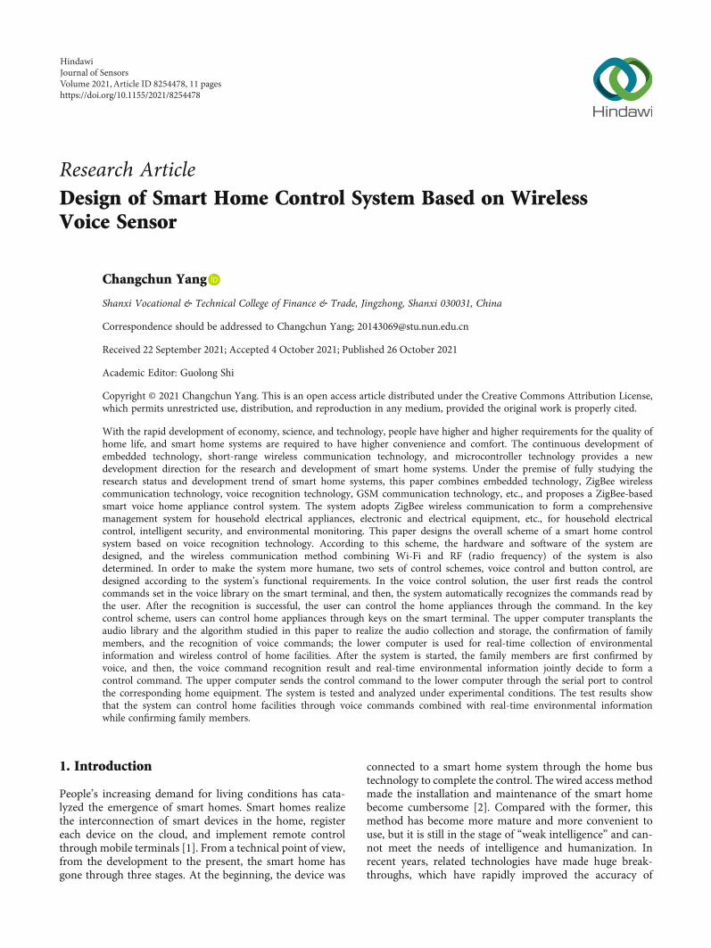
3.1. The Overall Structure Design of the System. The design ofthe ZigBee-based smart voice home appliance control sys-tem is mainly composed of four parts: remote control,receiver (security device), mobile phone, and householdappliances. Each part forms a household electrical appliancecontrol system through the ZigBee wireless network andGSM network. The specific structure is shown in Figure 1.The system realizes wireless networking through ZigBeetechnology and realizes the communication between theremote control and the receiving end through the wirelessnetwork, so as to send corresponding instructions to controlhousehold appliances, and users can realize remote controlof home appliances through the mobile phone GSM net-work. At the same time, the receiving end uses the ZigBeemodule to receive electrical control instructions and sendelectrical operating status and electrical fault informationto the remote control. The smart security device detectsthe intrusion of thieves through the infrared sensor module,and the buzzer alarms. Its ZigBee module sends informationto the remote control, and the remote control sends alarmmessages to the user’s mobile phone through the GSM net-work, realizing smart security to protect the user’s homesafety.
3.2. Design of Speech Recognition Module. The purpose ofsmart home is to improve the quality of home life. Reliablelanguage recognition technology brings great convenienceto life. This design adds a voice recognition module to thesystem remote control to achieve the effect of voice controlof the status of home appliances. Voice recognition technol-ogy is widely used, such as GPS navigation, voice-activatedsmart toys, and automatic vending systems. Speech recogni-tion technology is an important way to realize man-machinedialogue, and it has become an important direction ofresearch today. Through speech recognition technology, itis possible to use speech recognition as a device for man-machine dialogue, and the operation is more convenient,intelligent, and flexible. The voice module design usesLD3320 as the main control chip. The chip contains 48 pins,which can be divided into power pins, volume control andoutput pins, control pins, and clock input pins accordingto their functions. Through the external correspondingperipheral circuit, the voice recognition function is realized.The P0~P7, MD, RDB, CSB, INTB, WRB, RSTB, A0, andother control pins of the speech recognition moduleLD3320 chip are connected with 1K/10K pull-up resistorsto ensure the signal stability of the chip control port andassist the system to work stably; Pin 12 (MBS) is the micro-phone bias. To ensure that a floating voltage can be outputto the microphone, this pin is connected to an RC circuit.EQ1/EQ2/EQ3 speaker volume is connected to an external
3Journal of Sensors
auxiliary circuit to achieve the effect of adjusting the speakervolume. The LD3320 chip must be connected to an externalclock. It comes with a PLL frequency synthesizer that cangenerate the required frequency inside the chip. The chipcan accept an external clock frequency range of 4-48MHz.The voice recognition module is connected to the single-chip microcomputer through SPI. The STM32 single-chipmicrocomputer PA8 provides the clock for the LD3320,SDCK receives the SPI clock signal of the single-chip micro-computer, and SCS connects the single-chip microcomputerPB5. The RSTB reset pin is connected to the PB12 pin of themicrocontroller, and the INTB is connected to the PC1 pinas an interrupt output. MICP and MICN are used as inputpins to input voice signals.
3.3. Design of Power Supply and Charging Module. In orderto enhance the portability of the system, the power supplyuses a combination of a rechargeable lithium battery andan ordinary power supply. This makes the remote controllerof the system more flexible and more convenient. The powersupply module design uses a positive low-dropout regulatorASM1117 for voltage stabilization. The chip integrates over-heating and current limiting circuits, which can realize thefunctions of current limiting and overheating cut-off, andthe stable range is -40°C~125°C. The power module can pro-vide two voltages: one is 5.0V; the other is a stable 3.3Vpower supply provided by the ASM1117 voltage regulatorchip. Two capacitors are connected to the output ofASM1117 to improve voltage stability through filtering.
Connecting a diode to the output of the battery can effec-tively prevent the battery from being charged directly inthe reverse current direction.
The power supply is designed with a rechargeable lith-ium battery, so a charging module must be added to the cir-cuit to charge the battery. The system charging module usesthe TP4056 chip, which includes battery temperature detec-tion, undervoltage lockout, automatic charging, soft start,and dual battery status features such as output LED pins.
In this design, the charging module can work normallywhen the CE pin of the TP4056 chip in the charging moduleis connected to a high level. Pins 6 and 7 are connected toLED5 and LED4, respectively. When LED5 is on, it meansthat the phone is charging. When the battery is fullycharged, the two capacitors C9 and C10 achieve filteringand R7, R8, and R9 complete current limiting. The chargingmodule design can be excellently adapted to this design andimprove the portability and simplicity of the smart homesystem.
4. Software Design of Smart HomeControl System
4.1. Hidden Markov Speech Recognition Model. The hiddenMarkov model is a kind of mathematical statistical model,which is used to describe the process of transition fromone state to another. Because of this, we need to find variousstate parameters in the hidden Markov model from theobserved transition state and apply these parameters to the
Remotecontrol 1
GSM Zigbee
Remotecontrol 2
GSM Zigbee
Remotecontrol 3
GSM
Remotecontrol n
GSM
GSMnetwork
Cell phone 1 Cell phone 2 GSMnetwork
Receiver 1
Zigbee Relay
Receiver 2
Zigbee Relay
Receiver 3
Zigbee Relay
Receiver n
Zigbee Relay
Security device
Zigbee Triode
ZigBeenetwork
ZigBeenetwork
Waterheater
Drinkingfountain
Electriccurtain Light
Infrared sensormodule
Household appliances and infrared sensor modules
Wireless networking
Remote control ofhousehold appliances
Smartsecurity
ZigbeeZigbee
Figure 1: Overall scheme design of smart home control.
4 Journal of Sensors
speech recognition system. Compared with the Markovmodel, the state of the hidden Markov model is hidden.We cannot observe it intuitively. We can only infer itsstate based on the visible state and the probability of itshidden state. The more difficult part is to determine thehidden parameters in the process from the observableparameters and then use these parameters for the nextstep of analysis.
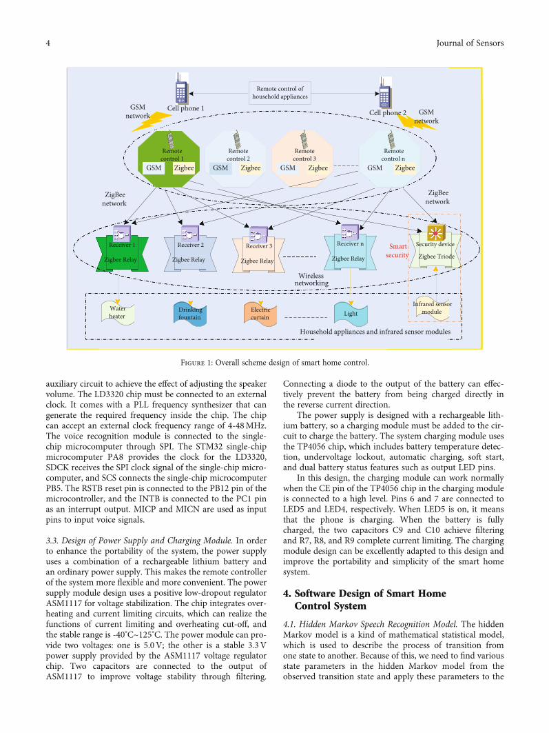
To use the hidden Markov model in speech recognition,the first step is to determine the topological form of the hid-den Markov model. The topological form of the hiddenMarkov model is distinguished according to the appearanceof the Markov chain, which can be divided into each stateergodic type, left-right type with spanning and left-right typewithout spanning.
The left-right model is widely used in speech recogni-tion, especially in the recognition of isolated words forunspecified persons. As shown in Figure 2, this is a left-right hidden Markov model without spanning. It can be seenfrom the figure that the four states from S1 to S4 can jumpover time or stay in this state.
“A” indicates the probability of a set of state transitions:
A = aij� �
, aij = P qt+1 = Sj−1, qt−1 = Si+1� �
, i, j ∈ 0,N − 1½ �:ð1Þ
“B” represents the distribution of observed symbol prob-ability in the Sj state:
B = bj+1 Okð Þ� �: ð2Þ
“Π” represents the probability of initial state distribution:
πi = P q1 = Si+1ð Þ, i ∈ 0,N + 1½ �: ð3Þ
The Baum-Welch algorithm can solve the template train-ing problem of the hidden Markov model, that is, the problemof data estimation of the hidden Markov model. Given asequence of observations O = O1, O2,⋯, OT, using theBaum-Welch algorithm, we can determine λ = ðπ, A, BÞ, sothat PðQ,O丨 λÞ is the maximum. From front to back vari-ables, there are
P O λjð Þ =YN−1
i=0
YN−1
j=0aijbi Ot−1ð Þαt ið Þβt j + 1ð Þ, t ∈ 0, T + 1½ �:
ð4Þ
In the formula, αt ðiÞ represents the output observationsequence O = O1, O2,⋯, OT, and the probability of reachingthe state θi, and βt + 1ðjÞ represents the number sequencestarting from the state Sj. Find λ so that PðQ,O丨 λÞ is themaximum value. This is a problem of extreme values of func-tional functions. Since the template training sequence is lim-ited, there is no best estimation method to estimate λ. TheBaum-Welch algorithm uses a recursive method to keep PðQ,O丨 λÞ locally maximized, and finally, the model parametersλ = ðπ, A, BÞ can be obtained.
We define ξt ði, jÞ as the probability that given the train-ing sequence O and the model λ, the Markov chain at time tis in the θi state and t + 1 is in the θj state, namely,
ξt i, jð Þ = P qt = θi, qt+1 = θj λj� �
: ð5Þ
At time t, the mathematical probability ξtðiÞ of theMarkov chain in the θi state is defined as
ξt ið Þ = P qt = θi λjð Þ =YN−1
j=0ξt i, jð Þ: ð6Þ
State 1 State 2 State 3 State 4
State 1 own transitionprobability
State 2 own transitionprobability
State 3 own transitionprobability
State 4 own transitionprobability
Probability of transitionbetween state 1 and state 2
Probability of transitionbetween state 2 and state 3
Probability of transitionbetween state 3 and state 4
Observationsymbol 3
Observationsymbol 1
Observationsymbol 2
Observationsymbol 4
Observationsymbol 5
Observationsymbol 6
Observationsymbol 7
Observationsymbol 8
Observationsymbol i
Distribution of observedsymbol probability for state 1
Distribution of observedsymbol probability for state 2
Distribution of observedsymbol probability for state 3
Distribution ofobserved symbol
probability forstate 4
No crossing left-right hidden Markov model Time
Figure 2: Hidden Markov model state transition diagram.
5Journal of Sensors

In this way, we have obtained the revaluation formula ofthe Baum-Welch algorithm:
aij′ =QT−1
t=0 ξt i, jð ÞQT−1
t=0 λ ið Þ,
bjk′ =QT−1
t=0 λ jð ÞQT−1
t=0 λ ið Þ:
ð7Þ
4.2. Software Development Environment Construction. Theconstruction of the software development environmentmainly includes the development environment of the PC ter-minal and the JZ2440 development board. The PC side isrelatively simple; we only need to install QT software editor,keil5 software tool, and Linux operating system. Utilizing theLinux system has the advantages of open source code, easycutting, convenient transplantation, security, and stability.The development environment of the JZ2440 developmentboard is built with an embedded Linux system. The con-struction process includes the transplantation of Bootloader,the transplantation of the kernel, and the production of theroot file system.
The version of U-boot used in this topic is U-boot-2012.04.01, and the kernel version is Linux-3.4.2. We buildthe required root file system and then burn the U-boot, ker-nel, and root file system. At this point, the developmentenvironment of the JZ2440 development board is completed.In order for the software written on the embedded operatingsystem to run on the ARM development board, you need toinstall the arm-linux-gcc cross-compiler in the embeddedsystem before setting up the ARM development environ-
ment. The cross-compiler version used in this topic is arm-linux-gcc-4.3.2 compiler. All the source code compressedpackages mentioned above can be downloaded from theInternet.
4.3. Main Control Center Software Design. As the server, themain control center is the main part of the smart home con-trol system and the hub that connects smart terminals andcontrol nodes. On the one hand, the main control center isresponsible for parsing the instructions sent from the smartterminal, and the instructions can be parsed into controlcommands or monitoring commands. If it is a control com-mand, the main control center will send the command to thecontrol node for processing; if it is a monitoring command,the main control center will process the stored video-play,close or forward. On the other hand, the main control centerreceives the response information fed back by the controlnode and feeds the response information back to the smartterminal. The main control center software design flow chartis shown in Figure 3.
4.4. RF Communication Protocol Design. Radio frequency isa communication method for wireless communicationbetween the main control center and each control node. Asthe nRF905 radio frequency module itself does not have net-working capabilities, a communication protocol is designedto make the system have networking capabilities.
In order to ensure orderly and reliable communicationbetween the main control center and each node, the addressof the main control center and each node is unique. Themain control center can communicate with all nodes in bothdirections, but it can only communicate with one node at a
Start Systeminitialization
Have you receivedinstructions from
the smartterminal?
Is there a controlcommand?
Is there a monitoringcommand?
Process monitoringcommands
Set the RF workingmode to transmit mode
Send control commands tothe control node
Set the RF workingmode to receiving mode
Yes
No
YesHave you received the
response messagefrom the control
node?
No
Send the response informationto the smart terminal
Yes
No
Yes
No
End
Figure 3: Flow chart of the software design of the main control center.
6 Journal of Sensors

time. The communication protocol data packet includes pre-amble, source address, destination address, control type, con-trol command, and CRC check code. The preamble and CRCcheck code are automatically generated by nRF905.
In the communication protocol data packet, the sourceaddress, destination address, and control type all occupy 1byte, and the control command occupies 2 bytes. Since thedefault address of the radio frequency module is 0x00, inorder to ensure the reliability of the system, the sourceaddress and destination are not 0. In this system, the maincontrol center address is 0x01, the infrared node addressrange is 0x01~0x8F, and the relay node address range is0x90~0xFF. Therefore, the system can support up to 143infrared nodes and 112 relay nodes, and each node can sup-port up to 65536 control commands, which can meet theneeds of most ordinary houses. The control type representsthe type of home appliances. The control types designed inthis article include 6 types of air conditioners, TVs, set-topboxes, fans, projectors, and sockets. When the main controlcenter sends data, the source address is set to 0x01, and thedestination address is set to the destination node address.When a node sends a response message to the master con-trol center, the source address is the address of each nodeitself, and the destination address is the master control cen-ter address 0x01. When sending a radio frequency signal, theprocessor packs the source address, destination address, andcontrol command together and sends it to nRF905. ThenRF905 will automatically load the preamble and CRC checkcode. After the load is successful, the signal can be sent out.When receiving a radio frequency signal, nRF905 first ver-ifies the preamble and CRC check code, and then, the pro-gram verifies the source address and destination address tocheck whether the signal is sent to itself; if not, ignore it; ifit is, then receive the signal.
4.5. Intelligent Terminal Voice Recognition Control SchemeDesign. The user first enters the login interface of the smarthome voice control system. In this interface, the user firstneeds to log in to the home gateway, and only under thehome gateway can the home appliances be controlled. Thissystem can only log in users who have already registered.Those who have not registered need to register before theycan log in. The user name and password registered by theuser are saved in the sqlite database of the main control cen-ter. A “super user login” is also designed under this interface.In this mode, users can add or delete control nodes.
When the “air conditioning” button is pressed, it entersthe voice air conditioning control interface; when the “TV”button is pressed, it enters the voice TV control interface.The user only needs to press and hold the voice input button.If the voice input by the user can match the voice in the voicelibrary, the voice control function can be realized. If the matchfails, the user will be prompted. The voice control function ofother infrared home appliances is similar to this.
5. System Function Test and Analysis
5.1. Experimental Program. According to the composition ofthe personnel making the speech library, the experimental
site simulates the real home environment, and the key labo-ratory of ordinary noise perception technology and intelli-gent system is selected. The mini model is chosen to beinstalled in the laboratory to simulate the entire home envi-ronment. The light, temperature, and humidity of naturalconditions are used to simulate the changes of home envi-ronment parameters. The curtains, bedroom lights, and liv-ing room lights are replaced by mini curtains and lamptubes, and two mini fans are used to simulate air condition-ing cooling and heating command signals. The TV controlsignal is replaced by indicator lights, and the remaining indi-cator lights are used to show that it is convenient to addhome facilities at any time.
A simple model is used to simulate the home environ-ment, and a smart home embedded control system modelbased on voice perception is used to conduct experimentsto test the confirmation effect of real family members andtest the control effect of the fusion of home environmentinformation with the voice perception recognition result onthe simulated home facilities.
The different member thresholds shown in Figure 4 areused in the experiment. After the system is started, the audiocodec chip collects the voices of the testers for 5 s from 100members, calculates the likelihood, and obtains the corre-sponding correct rate. In the actual environment, environ-mental conditions are artificially changed. In order toachieve better and more obvious effect, this paper sets theenvironmental parameter threshold as shown in Figure 5.Except for the system wake-up command, the experimentaltests are all tested.
5.2. Environmental Information Collection Control Test. Thecommunication between the host computer and the coordi-nator is completed through the serial port. The environmen-tal information collection and the test of the control modulein this article are carried out through the serial port debug-ging assistant on the PC. It is equivalent to the control com-mand sent by the upper computer to the lower computer,which makes the test process more clear. First, insert thedesigned lower-level computer coordinator into the USBinterface of the PC; then, check the serial port number; openthe serial debugging assistant software, strictly follow theserial port structure in the serial communication programdesign to set the serial port, and finally open the serial port.
Turn on the coordinator switch, and power on the acqui-sition node and the control node, and wait 3 seconds tocomplete the networking and network access. Finally, thequery and control commands are sent to the coordinatorthrough the serial port. You perform environmental infor-mation acquisition test according to the query command.You can get a single command to control each device asshown in Table 1. After testing, the coordinator is correctlynetworked after power-on, and each node is correctly con-nected to the network; when the configuration of the serialport structure is consistent, the command is sent in hexadec-imal, and the data transmission and control are error-free,and the functional design fully meets the control require-ments. The control of the scene mode is equivalent to thecontrol of all devices together, and the system selects two
7Journal of Sensors

modes: sleeping mode and away from home mode. Thetime-consuming result of the scenario mode test is shownin Figure 6.
5.3. Test Results of Overall System Control Effect. After thecollected audio features are extracted, the likelihood is calcu-lated, and the maximum likelihood is obtained, and it is
0 5 10 15 200.07
0.08
0.09
0.1
0.11
0.12
0.13
0.14
0.15
Time/h
TemperatureHumidityIllumination
Nor
mal
ized
thre
shol
d of
envi
ronm
enta
l par
amet
ers
Figure 5: Normalized threshold experiment of environmental parameters.
Table 1: Control device command data format.
Smart home control equipment Control command (open) Control command (closed)
Living room lights 1A 00 01 06 01 1E 21 1A 00 01 06 00 1F 21
Bedroom lights 1A 00 01 05 01 1D 21 1A 00 01 05 00 1C 21
Air conditioning and refrigeration 1A 00 01 01 01 1B 21 1A 00 01 01 00 1A 21
Air conditioning and heating 1A 00 01 08 00 10 21 1A 00 01 09 01 10121
Curtain 1A 00 01 04 01 1C 21 1A 00 01 04 00 1D 21
Television 1A 00 01 07 01 1F 21 1A 00 01 07 00 1E 21
0 10 20 30 40 50 60 70 80 90 1000.1
0.11
0.12
0.13
0.14
0.15
0.16
0.17
0.18
0.19
100 members
Nor
mal
ized
thre
shol
d
Figure 4: Normalized threshold for 100 members.
8 Journal of Sensors

judged whether the maximum is within the threshold rangeof the corresponding number of the maximum. If it iswithin the threshold, it is confirmed as a family member.The statistical results of confirmation of family membersare shown in Figure 7. It can be seen that the confirmationaccuracy rates of family members under different thresholdsare all above 90%.
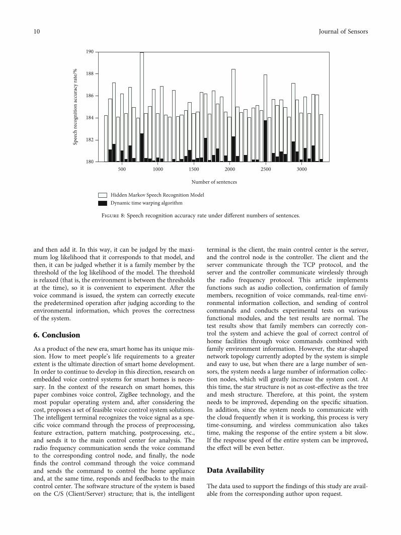
After actual tests in different environments, the systemcan work as designed. Figure 8 is the summary statisticalresults of speech recognition accuracy corresponding to thenumber of different sentences.
If you want to observe the specific execution of the sys-tem, you can connect the serial port of the host computerto the securtCRT terminal and set the corresponding proto-
col. After the system is turned on, you can see the executionof the system in the terminal.
In the confirmation and recognition of family members,the selection of the threshold directly affects the recognitionrate, and the threshold setting is to prevent people who arenot family members from controlling the smart home sys-tem. If the threshold is set too high, the effect of improvingsystem security can be achieved, but it will cause a drop inthe correct recognition rate. Therefore, the threshold settingshould be determined based on actual measurement. Thereason why the log likelihood result is negative is that theprobability is a number less than 1. If these probabilitiesare multiplied, it is close to 0. In order to reduce the error,we take the logarithm of the probability to a negative value,
0 10 20 30 40 50 60 70 80 90 1000.5
1
1.5
2
2.5
3
3.5
4
4.5
5
5.5
100 members
Away from home modeSleep mode
Tim
e con
sum
ing
of sc
enar
io m
ode t
estin
g/s
Figure 6: Time consumption of scenario mode testing.
0 0.1 0.2 0.3 0.4 0.5 0.6 0.7 0.8 0.9 190
91
92
93
94
95
96
97
98
Different thresholds
Confi
rmat
ion
accu
racy
rate
of
fam
ily m
embe
rs/%
Figure 7: Confirmation accuracy rate of family members under different thresholds.
9Journal of Sensors
and then add it. In this way, it can be judged by the maxi-mum log likelihood that it corresponds to that model, andthen, it can be judged whether it is a family member by thethreshold of the log likelihood of the model. The thresholdis relaxed (that is, the environment is between the thresholdsat the time), so it is convenient to experiment. After thevoice command is issued, the system can correctly executethe predetermined operation after judging according to theenvironmental information, which proves the correctnessof the system.
6. Conclusion
As a product of the new era, smart home has its unique mis-sion. How to meet people’s life requirements to a greaterextent is the ultimate direction of smart home development.In order to continue to develop in this direction, research onembedded voice control systems for smart homes is neces-sary. In the context of the research on smart homes, thispaper combines voice control, ZigBee technology, and themost popular operating system and, after considering thecost, proposes a set of feasible voice control system solutions.The intelligent terminal recognizes the voice signal as a spe-cific voice command through the process of preprocessing,feature extraction, pattern matching, postprocessing, etc.,and sends it to the main control center for analysis. Theradio frequency communication sends the voice commandto the corresponding control node, and finally, the nodefinds the control command through the voice commandand sends the command to control the home applianceand, at the same time, responds and feedbacks to the maincontrol center. The software structure of the system is basedon the C/S (Client/Server) structure; that is, the intelligent
terminal is the client, the main control center is the server,and the control node is the controller. The client and theserver communicate through the TCP protocol, and theserver and the controller communicate wirelessly throughthe radio frequency protocol. This article implementsfunctions such as audio collection, confirmation of familymembers, recognition of voice commands, real-time envi-ronmental information collection, and sending of controlcommands and conducts experimental tests on variousfunctional modules, and the test results are normal. Thetest results show that family members can correctly con-trol the system and achieve the goal of correct control ofhome facilities through voice commands combined withfamily environment information. However, the star-shapednetwork topology currently adopted by the system is simpleand easy to use, but when there are a large number of sen-sors, the system needs a large number of information collec-tion nodes, which will greatly increase the system cost. Atthis time, the star structure is not as cost-effective as the treeand mesh structure. Therefore, at this point, the systemneeds to be improved, depending on the specific situation.In addition, since the system needs to communicate withthe cloud frequently when it is working, this process is verytime-consuming, and wireless communication also takestime, making the response of the entire system a bit slow.If the response speed of the entire system can be improved,the effect will be even better.
Data Availability
The data used to support the findings of this study are avail-able from the corresponding author upon request.
500 1000 1500 2000 2500 3000180
182
184
186
188
190
Number of sentences
Hidden Markov Speech Recognition ModelDynamic time warping algorithm
Spee
ch re
cogn
ition
accu
racy
rate
/%
Figure 8: Speech recognition accuracy rate under different numbers of sentences.
10 Journal of Sensors

Conflicts of Interest
The author declares that they have no known competingfinancial interests or personal relationships that could haveappeared to influence the work reported in this paper.
References
[1] M. Murad, O. Bayat, and H. M. Marhoon, “Design and imple-mentation of a smart home system with two levels of securitybased on IoT technology,” Indonesian Journal of ElectricalEngineering and Computer Science, vol. 21, no. 1, pp. 546–557, 2021.
[2] T. Y. Kim, S. H. Bae, and Y. E. An, “Design of smart homeimplementation within IoT natural language interface,” IEEEAccess, vol. 8, pp. 84929–84949, 2020.
[3] Y. Changshun and S. Yong, “Research on security evaluationindicator system of smart home,” American Journal of Net-works and Communications, vol. 9, no. 1, pp. 11–16, 2020.
[4] M. C. Chiu, W. D. Lai, and C. M. Chiu, “A smart home systemwith security and electrical appliances,” Journal of Informationand Optimization Sciences, vol. 42, no. 2, pp. 303–319, 2021.
[5] M. M. A. Zahra, M. J. Mohsin, and L. A. Abdul-Rahaim, “Arti-ficial intelligent smart home automation with secured cameramanagement-based GSM, cloud computing, and arduino,”Periodicals of Engineering and Natural Sciences (PEN), vol. 8,no. 4, pp. 2160–2168, 2020.
[6] C. Hermanu, H. Maghfiroh, H. P. Santoso, Z. Arifin, andC. Harsito, “Dual mode system of smart home based on inter-net of things,” Journal of Robotics and Control (JRC), vol. 3,no. 1, pp. 26–31, 2022.
[7] A. I. Abdulla, A. S. Abdulraheem, A. A. Salih et al., “Internet ofthings and smart home security,” Technology Reports of KansaiUniversity, vol. 62, no. 5, pp. 2465–2476, 2020.
[8] N. al-Shareefi, S. A. Abbas, M. S. Alkhazraji, and A. A. R.Sakran, “Towards secure smart cities: design and implemen-tation of smart home digital communication system,” Indo-nesian Journal of Electrical Engineering and ComputerScience, vol. 21, no. 1, pp. 271–277, 2021.
[9] F. Alfiah and B. Rahman, “Control system prototype smarthome IoT based with MQTT method using Google Asisstant,”Jurnal RESTI (Rekayasa Sistem Dan Teknologi Informasi),vol. 4, no. 2, pp. 303–310, 2020.
[10] J. Ding and Y.Wang, “AWiFi-based smart home fall detectionsystem using recurrent neural network,” IEEE Transactions onConsumer Electronics, vol. 66, no. 4, pp. 308–317, 2020.
[11] D. N. Mekuria, P. Sernani, N. Falcionelli, and A. F. Dragoni,“Smart home reasoning systems: a systematic literaturereview,” Journal of Ambient Intelligence and Humanized Com-puting, vol. 12, no. 4, pp. 4485–4502, 2021.
[12] S. Shenbagavalli, T. Priyadharshini, S. Sowntharya,P. Manikandan, and D. S. Saravanan, “Design and implemen-tation of smart traffic controlling system,” International Jour-nal of Engineering Technology Research & Management,vol. 4, no. 4, pp. 28–36, 2020.
[13] A. A. Zaidan and B. B. Zaidan, “A review on intelligent processfor smart home applications based on IoT: coherent taxon-omy, motivation, open challenges, and recommendations,”Artificial Intelligence Review, vol. 53, no. 1, pp. 141–165, 2020.
[14] A. Modarresi and J. Symons, “Technological heterogeneity andpath diversity in smart home resilience: a simulation
approach,” Procedia Computer Science, vol. 170, pp. 177–186,2020.
[15] Ö. Gül and U. Bayrak, “A smart home system based on micro-controller using android application and MySQL database,”Academic Perspective Procedia, vol. 3, no. 1, pp. 455–464, 2020.
[16] M. A. Paredes-Valverde, G. Alor-Hernández, J. L. García-Alcaráz, M. . P. Salas-Zárate, L. O. Colombo-Mendoza, andJ. L. Sánchez-Cervantes, “IntelliHome: an internet of things-based system for electrical energy saving in smart home envi-ronment,” Computational Intelligence, vol. 36, no. 1, pp. 203–224, 2020.
[17] B. D. Davis, J. C. Mason, and M. Anwar, “Vulnerability studiesand security postures of IoT devices: a smart home case study,”IEEE Internet of Things Journal, vol. 7, no. 10, pp. 10102–10110, 2020.
[18] M. Vidya, “Smart home automation using Wi-Fi technology,”Journal of Research Proceedings, vol. 1, no. 2, pp. 167–175,2021.
[19] L. K. Aagaard, “The meaning of convenience in smart homeimaginaries: tech industry insights,” Buildings and Cities,vol. 2, no. 1, pp. 568–582, 2021.
[20] S. Leem and S. W. Lee, “Smart-textronics product develop-ment process by systematic participatory design method,”Journal of the Korea Convergence Society, vol. 12, no. 1,pp. 163–170, 2021.
11Journal of Sensors