Design of Slab for Bending
6
Benchmark Example No. 1 Design of Slab for Bending SOFiSTiK | 2022
Transcript of Design of Slab for Bending
Benchmark Example No. 1
Design of Slab for Bending
SOFiSTiK | 2022

VERiFiCATiONDCE-EN1 Design of Slab for Bending
VERiFiCATiON Manual, Service Pack 2022-3 Build 53
Copyright © 2022 by SOFiSTiK AG, Nuremberg, Germany.
SOFiSTiK AG
HQ Nuremberg Office Garching
Flataustraße 14 Parkring 2
90411 Nurnberg 85748 Garching bei Munchen
Germany Germany
T +49 (0)911 39901-0 T +49 (0)89 315878-0
F +49(0)911 397904 F +49 (0)89 315878-23
This manual is protected by copyright laws. No part of it may be translated, copied or reproduced, in any form or byany means, without written permission from SOFiSTiK AG. SOFiSTiK reserves the right to modify or to release
new editions of this manual.
The manual and the program have been thoroughly checked for errors. However, SOFiSTiK does not claim thateither one is completely error free. Errors and omissions are corrected as soon as they are detected.
The user of the program is solely responsible for the applications. We strongly encourage the user to test thecorrectness of all calculations at least by random sampling.
Front Cover
Arnulfsteg, Munich Photo: Hans Gossing
Design of Slab for Bending
Overview
Design Code Family(s): DIN
Design Code(s): DIN EN 1992-1-1
Module(s): AQB
Input file(s): slab bending.dat
1 Problem Description
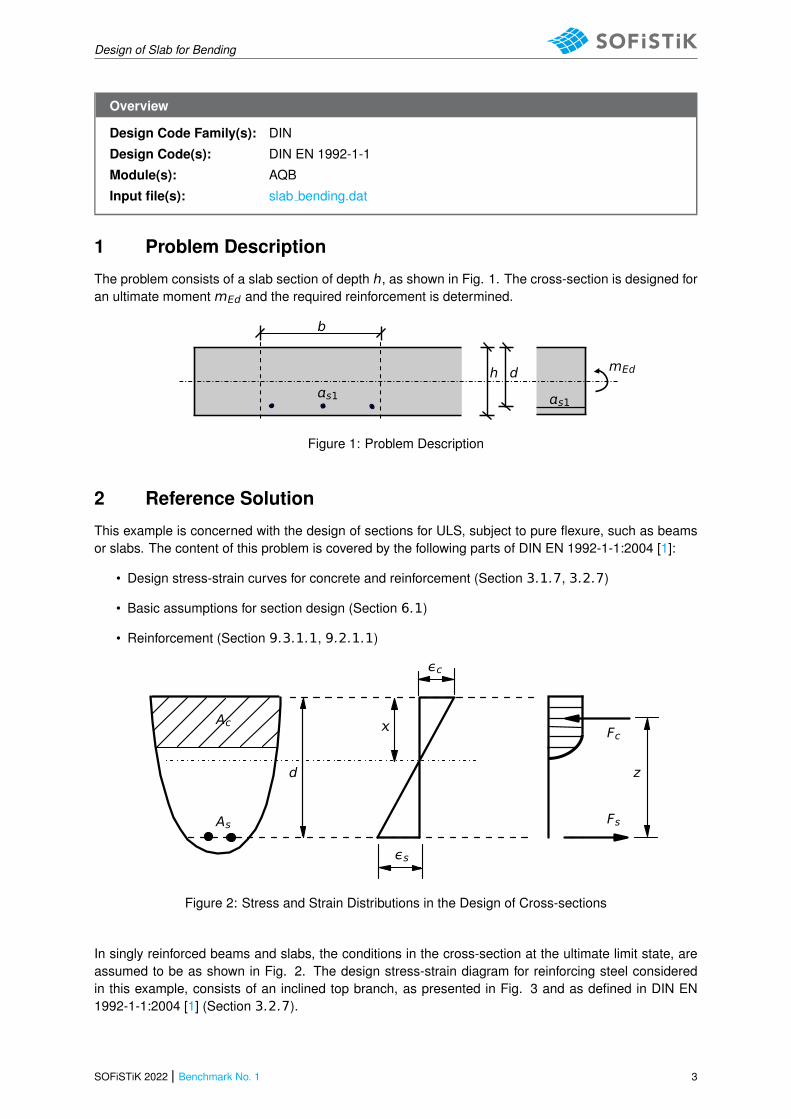
The problem consists of a slab section of depth h, as shown in Fig. 1. The cross-section is designed foran ultimate moment mEd and the required reinforcement is determined.
mEd
s1s1
b
dh
Figure 1: Problem Description
2 Reference Solution
This example is concerned with the design of sections for ULS, subject to pure flexure, such as beamsor slabs. The content of this problem is covered by the following parts of DIN EN 1992-1-1:2004 [1]:
• Design stress-strain curves for concrete and reinforcement (Section 3.1.7, 3.2.7)
• Basic assumptions for section design (Section 6.1)
• Reinforcement (Section 9.3.1.1, 9.2.1.1)
εc
εs
z
Fc
Fs
d
As
Ac
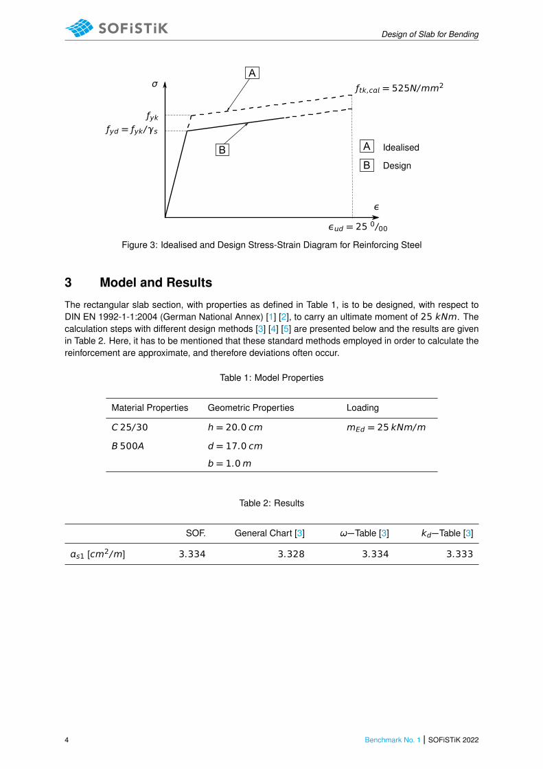
Figure 2: Stress and Strain Distributions in the Design of Cross-sections
In singly reinforced beams and slabs, the conditions in the cross-section at the ultimate limit state, areassumed to be as shown in Fig. 2. The design stress-strain diagram for reinforcing steel consideredin this example, consists of an inclined top branch, as presented in Fig. 3 and as defined in DIN EN1992-1-1:2004 [1] (Section 3.2.7).
SOFiSTiK 2022 | Benchmark No. 1 3
Design of Slab for Bending
A
B A
B
Idealised
Design
ƒyk
ƒtk,c = 525N/mm2
ε
εd = 25 0/00
ƒyd = ƒyk/γs
σ
Figure 3: Idealised and Design Stress-Strain Diagram for Reinforcing Steel
3 Model and Results
The rectangular slab section, with properties as defined in Table 1, is to be designed, with respect toDIN EN 1992-1-1:2004 (German National Annex) [1] [2], to carry an ultimate moment of 25 kNm. Thecalculation steps with different design methods [3] [4] [5] are presented below and the results are givenin Table 2. Here, it has to be mentioned that these standard methods employed in order to calculate thereinforcement are approximate, and therefore deviations often occur.
Table 1: Model Properties
Material Properties Geometric Properties Loading
C 25/30 h = 20.0 cm mEd = 25 kNm/m
B 500A d = 17.0 cm
b = 1.0m
Table 2: Results
SOF. General Chart [3] ω−Table [3] kd−Table [3]
s1 [cm2/m] 3.334 3.328 3.334 3.333
4 Benchmark No. 1 | SOFiSTiK 2022

Design of Slab for Bending
4 Design Process1
Design with respect to DIN EN 1992-1-1:2004 (NA) [1] [2]:2
Material:
Concrete: γc = 1.50 (NDP) 2.4.2.4: (1), Tab. 2.1DE: Partialfactors for materialsSteel: γs = 1.15
ƒck = 25 MP Tab. 3.1: Strength for concrete
ƒcd = cc · ƒck/γc = 0.85 · 25/1.5 = 14.17 MP 3.1.6: (1)P, Eq. (3.15): cc = 0.85 con-sidering long term effects
ƒyk = 500 MP 3.2.2: (3)P: yield strength ƒyk = 500
MPƒyd = ƒyk/γs = 500/1.15 = 434.78 MP3.2.7: (2), Fig. 3.8
Design Load:
MEd =mEd · b = 25 kNm; NEd = 0MEds = MEd − NEd · zs1 = 25 kNm
Design with respect to General Design Chart Bending with axialforce for rectangular cross-sections:
μEds =MEds
b · d2 · ƒcd=
25 · 10−3
1.0 · 0.172 · 14.17= 0.061
Tab. 9.1 [3]: General Chart for up toC50/60 - Cross-section without com-pression reinforcement
ε = 25 · 10−3; ζ = 0.97 → σs1d = 456.52 MP
s1 =1
σs1d·�
MEds
ζ · d+ NEd
�
= 3.328 cm2/m
Design with respect to ω− (or μs− ) Design Table for rectangularcross-sections:
μEds =MEds
b · d2 · ƒcd=
25 · 10−3
1.0 · 0.172 · 14.17= 0.061
Tab. 9.2 [3]: ω−Table for up to C50/60- Rectangular section without compres-sion reinforcement
ω = 0.0632 (interpolated) and σsd = 456.52 MP
s1 =1
σsd· (ω · b · d · ƒcd + NEd) = 3.334 cm2/m
Design with respect to kd− Design Table for rectangular cross-sections:
kd =d
p
MEds/b=
17p
25/1.0= 3.40
Tab. 9.3 [3]: kd−Table for up toC50/60 - Rectangular section withoutcompression reinforcementks = 2.381, κs = 0.952 (interpolated values)
s1 =�
ks ·MEds
d+NEd
σs1d
�
· κs = 3.333 cm2/m
1The tools used in the design process are based on steel stress-strain diagrams, asdefined in [1] 3.2.7:(2), Fig. 3.8, which can be seen in Fig. 3.
2The sections mentioned in the margins refer to DIN EN 1992-1-1:2004 (German Na-tional Annex) [1], [2], unless otherwise specified.
SOFiSTiK 2022 | Benchmark No. 1 5
Design of Slab for Bending
5 Conclusion
This example shows the calculation of the required reinforcement for a slab section under bending.Various different reference solutions are employed in order to compare the SOFiSTiK results to. It hasbeen shown that the results are reproduced with excellent accuracy.
6 Literature
[1] DIN EN 1992-1-1/NA: Eurocode 2: Design of concrete structures, Part 1-1/NA: General rules andrules for buildings - German version EN 1992-1-1:2005 (D), Nationaler Anhang Deutschland - StandFebruar 2010. CEN. 2010.
[2] F. Fingerloos, J. Hegger, and K. Zilch. DIN EN 1992-1-1 Bemessung und Konstruktion vonStahlbeton- und Spannbetontragwerken - Teil 1-1: Allgemeine Bemessungsregeln und Regeln furden Hochbau. BVPI, DBV, ISB, VBI. Ernst & Sohn, Beuth, 2012.
[3] K. Holschemacher, T. Muller, and F. Lobisch. Bemessungshilfsmittel fur Betonbauteile nach Eu-rocode 2 Bauingenieure. 3rd. Ernst & Sohn, 2012.
[4] Beispiele zur Bemessung nach Eurocode 2 - Band 1: Hochbau. Ernst & Sohn. Deutschen Beton-und Bautechnik-Verein E.V. 2011.
[5] R. S. Narayanan and A. W. Beeby. Designers’ Guide to EN 1992-1-1 and EN 1992-1-2 - Eurocode2: Design of Concrete Structures. Thomas Telford, 2005.
6 Benchmark No. 1 | SOFiSTiK 2022