DESIGN OF RECTANGULAR~STRUCTURAL …sites.cs.ksu.edu/tr42/tr50.pdfdeal with the structural design of...
78
LJ. S. Department of Agriculture Soil Conservation Service Engineering Division Technical Release No. 50 (Rev. 1) Design Unit July 1977 -r DESIGN OF RECTANGULAR~STRUCTURAL CHANNELS
Transcript of DESIGN OF RECTANGULAR~STRUCTURAL …sites.cs.ksu.edu/tr42/tr50.pdfdeal with the structural design of...

LJ. S. Department of Agriculture Soil Conservation Service Engineering Division
Technical Release No. 50 (Rev. 1) Design Unit July 1977
-r
DESIGN OF RECTANGULAR~STRUCTURAL CHANNELS


PREFACE
This technicsl release continues the effort to produce design aids which facilitate the attempt towards optimization of structural design. Three earlier technical releases, m-42, TR-43, and TR-45, deal with the structural design of rectangular conduits. This technical release is concerned with the structural. design of rec- tangular channels. Although primarily written for design engineers, the materi& has considerable application for planning engineers since preliminsxy designs of structural channels are readily avail- able to them.
A draft of the subject technical release dated August, 1971, was sent to the Engineering and Watershed Planning Unit Design Engineers for their review and comment.
This technic&L release was prepared by Mr. Edwin S. Ailing of the Design Unit, Design Branch at Hyattsville, Maryland. He also wrote the computer program.


i
TECHNICAL RELEASE NUMBER 50
DESIGN OF RECTANGULAR STRUCTURAL CHANNELS
Contents
Introduction
Types of Structural Channels Type TlF Type T3F Type T3N Type TlS
Loading Conditions Loading Condition No. 1 Loading Condition No. 2 Flotation Requirement Surcharge
Design Parameters Primary Parameters Secondary Parameters
Design Criteria
Preliminary Designs Type TlF
Wall thicknesses Flotation Floor slab shear Floor slab bearing
Type T3F Base design Pavement slab thickness
Type T3FV Determination of joint shear Design approach Wall base flotation Base design Pavement slab thickness Delta Q
Type TM Edge beam analyses Design approach Edge beam loading Strut design Edge beam design Wall design Flotation requirements and floor slab shear Floor slab bearing
6
8
9 9 9
10 11 12
13 13 16
17 17 19 1-9 19 19 20
21 22 25 25 28 29 30 32 32
Revised 7/77

ii
Detail Designs Floor Slab Analysis
Deflection, shear, and moment due to NW Deflection, shear, and moment due to MM Deflection, shear and moment due to uniform loading, q Deflection, Solution for
shear, and moment due to Q. and &lo Q. and M.
Solution for finite beam
%w TIE 41 Wall steel 41 Floor slab steel 42
Tyw T3F 45 Sliding stability of base 45 Base slab steel 47 Pavement slab steel 48
Qpe T3Fv Shear joint requirements Base slab steel Pavement slab steel
Type TlS Wall steel Floor slab steel Edge beam steel Edge beam stirrups
Computer Designs Input output
Preliminary designs Detail designs
Type TlF Type T3F Type T3FV Type TlS
;7’ 38
49 49 50 51
:il 54

Figure 1 Figure 2 Figure 3 Figure 4 Figure 5 Figure 6 Figure 7 Figure 8 Figure 9 Figure 10
Figure Ill Figur--12 Figure 13 Figure 14 Figure 15 Figure 16 Figure 17 Figure 18 Figure 19
Figure 20
Figure 21 Figure 22 Figure 23
Figure 24 Figure 25 Figure 26 Figure 27 Figure 28 Figure 29 Figure 30
Figure 31 Figure 32 Figure 33 Figure 34 Figure 35 Figure 36 Figure 37 Figure 38 Figure 39 Figure 40
Figure 41 Figure 42
Figures Page
Structural channel types. Load condition No. 1. Load condition No. 2. Flotation conditions. Thickness TB for LC#l when BB > HKL. Flotation condition, K!#l when HB > HWl. Bearing pressures, LC#l when m > BWl. Investigation of footing shears. Pavement slab flotation, type T3F. Joint shears in type T3FV channels.
Base pressures concerned with joint shears. Pavement slab flotation, type T3FV. Definition sketch, type TlS channel. Rxsible strut-to-wall connections. Edge beam loading and displacement. Type TlS frame displacements, typical loading. Alternate method of solution for edge beam analyses. Evaluation of frame U and n. Vertical forces involved with frame T and m, LC#2 when Hb>Hw2. Floor slab loads and moments for frame T and m.
Sense of positive edge beam loading. Fdge beam section. Shear at top of wall; IC#l when HB > I-lWl, BTB < EB/12, and HKl < BIT - EB/12. Shear and moment at bottom of wall, LC#l when I-II3 > HWl. Finite length beam and loading. Uniform loading cases, infinite beams. Q. and M. loadings, infinite beam. Corrections for indicated tensile reactions. Type TlF steel layout and point locations. Wall steel design for K!#l, HB > BWL, and Z > BTW.
Floor slab analysis and loadings for IC#l when HB < I-ML. Determination of form of shear and moment computations. Type T3F steel lsyout and point locations. Sliding of type T3F retaining wall portion. Contact pressure distribution for LC#2. Type T3F'V steel layout and point locations. Direct tension through shear joint for I&&. Pavement design for LC#l, &1 > 0. Type TlS steel layout and point locations. Plan of edge beam, steel layout and point locations.
Edge beam loading for LC#l when Layout of edge beam stirrups.
RXL > 0.
4
z 6 9
11 14 15 16 17
18 19 21 22 22 22 23 25
26 27
28 29
30
;i 36
;i 41 42
43 44 45 46 47 49 50 51
:z

iV
Figure 43 Computer output, preliminary designs. TlF detail design. TlF detail design.
Figure 44 Figure 45 Figure 46 Figure 47 Figure 48 Pigure 49 Figure 50 Figure 51
Computer output, type Computer output, type Computer output, type Computer output, type Computer output, type Computer output, type Computer output, type Computer output, type
T3F detail design. T3F detail design. T3FV detail design. T3FV detail design. TlS detail design. TlS detail design.
Tables
Table 1 Secondary parameters and default values. Table 2 Input values per design run.

V
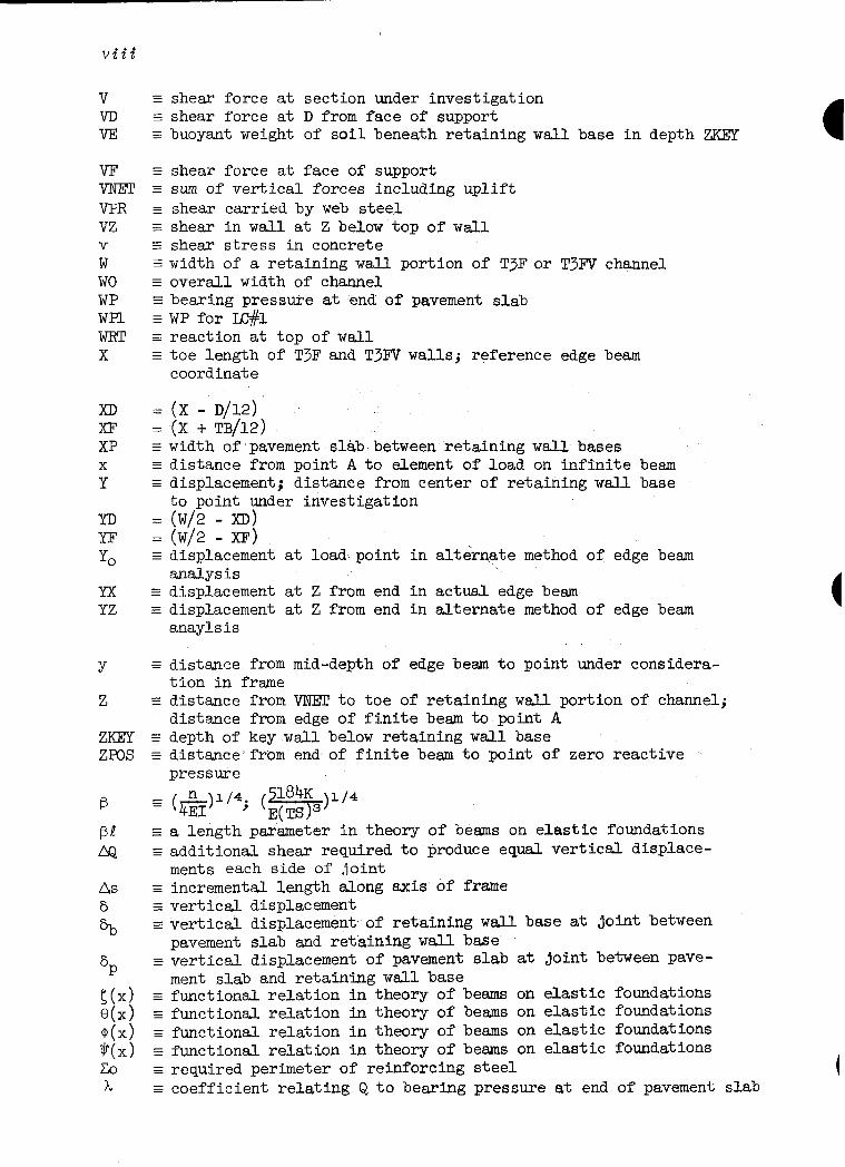
Not all nomenclature is listed. Hopefully, the meaning of any un- listed nomenclature may be ascertained from that shown.
A ACOMP AE AG ATENS
AV
; BFGR b
C
CB CF CFSC CFSS
; E
EB ET
EKEY
= -
= -
= -
= -
= -
= -
G
= -
=
E
E
E
E
E
E
= -
= -
E
E
I
= -
E
required reinforcing steel area required compressive steel area in strut equivalent edge beam steel area per foot width gross area of strut required tensile steel area in TlS strut; required tensile steel through T3FV shear joint area of web steel, equals twice bar area distance from point A to beginning of load on infinite beam clear width of channel (B + TB/12) width of reinforced concrete member; distance from point A to end of loading on infinite beam JOmSj distance to extreme fiber
direct compressive force in floor slab between walls direct compressive force in the footing projection coefficient of friction, soil to concrete coefficient of friction, soil to soil distance from point A to left end of load on infinite beam effective depth of concrete section; diameter of reinforcing bar eccentricity of VNEZj eccentricity of RC due to MD; modulus of elasticity of concrete width of edge beam thickness of edge besm
distance from point A to right end of load on infinite beam horizontal force acting on key wall safety factor against flotation footing projection compressive stress in concrete stress in reinforcing steel GsAT - 62.4 moist unit weight of backfill saturated unit weight of backfill height of backfill above top of floor slab
(HB - D/12) (HT - EB/l2) (HB-HWl) or(HB-RW2) horizontal force of water in channel on retaining wall portion ofchannel components of horizontal load on the wall additional lateral earth force caused by key wsll sum of resisting horizontal. forces on retaining wall portion of channel (HE3 + TS/12) height of wall above top of floor slab (Ifll - HB)

Vi
HIW Hwl IN2 HWALL
RWP I J JOINTS
ii KOl K02 KPASS L E#l wk M MAXFTG
MB ME3P MC MD ME MFOUND MFTG
M,
MR
MI-
MS MSUP
Mw
MWALL
Mz m N NSHT
NW
NWALL
=
=
E
s
E =
G
E = = -
E
s = -
e
G = - = -
f = - = -
E = -
= = - = - = - = -
e = -
ZZ
f
F
E
= -
= -
= - = - ZZ - = -
= -
E
(m - I-Is& (HWl + TS/12) submergence height above top of floor slab for Lc#l submergence height above top of floor slab for I&2 totsl horizontal loading on the wall (RWl - D/12) uplift head on pavement slab moment of inertia (FE + TB/24) longitudinal span between transverse joints
ratio used in reinforced concrete design MFOUND lateral earth pressure ratio for LC#l lateral earth pressure ratio for LC#2 passive lateral earth pressure ratio span of finite beam load condition number one load condition number two bending moment at section under investigation maximum acceptable footing projection
simple moment due to ER on B simple moment due to PGR on BPGR (MWALL + MFCG) maximum dead load moment in strut equivalent edge beam moment per foot width modulus of the foundation moment at junction of stem wall and footing projection due to loads on footing projection key wall design moment overturning moment about toe of retaining wall portion of channel; fecticious moment at ends of finite beam on elastic foundation (MBP -MB)
resisting moment about toe of retaining wall portion of channel equivalent moment, moment about axis at the tension steel supplemental moment added to end of finite beam when 0 < ZPOS J simple moment due to water in channel; moment applied to floor slab at wall moment at junction of stem wall and footing projection due to loads on wall moment in wall at Z below top of wall T/U, TlS frame constant direct force at section under investigation assumed direct compressive force in pavement slab due to water in channel concentrated load applied to floor slab at wall
direct force brought by the wall to the floor slab of TIS channel

Nx = NY NZ : n - = P - ZZ Pl E Pll E I?2 E PADIOWz
PB PD FT
FFTG PGR Ps PUP pt Q
QJ
&JP
R" RC RS Rsl RT Rx
- ZZ - ZZ
= - = -
E = - = - = -
= -
= -
f
= - = - = -
E = - = - = -
z
RY S SB ST sz T
TP TS TT t U U
Vii
RC/RX RC/RY direct force in wall at Z below top of wall l/U, TlS frame constant intergranular bearing pressure; foundation pressure bearing (contact) pressure at toe of retaining wall base Pl for LC#l bearing (contact) pressure at heel of retaining wall base maximum allowable bearing (contact) pressure
uniform loading on floor slab between wEiLls bearing (contact) pressure at D from face of support bearing (contact) pressure at face of support; uniform load- ing on footing portions of floor slab overburden pressure on footing projection gross pressure on TlS floor slab uniform loading causing shear in floor slab uplift pressure on bottom of slab temperature and shrinkage steel ratio shear transmitted across the joint between pavement slab and retaining wall base of T3FV channel Q for LC#l
fictitious shear at ends of finite beam on elastic foundation supplemental shear added to end of finite beam when O<ZPOS S J uniform loading on infinite beam ratio of downward forces on channel to the uplift forces maximum compressive force in strut maximum edge beam reaction provided by strut E&S for LC#l maximum tensile force in strut edge beam loading; correction factor for long column buckling about X axis RX for LC#l
maximumvalue of any RXl minimumvalue of any RXl correction factor for long column buckling about Y axis maximum allowable spacing of reinforcing steel width of strut thickness of strut maximum allowable spacing of steel at Z below top of w6l.l thickness of section under investigation; displacement at top of TlS frame with struts removed thickness of bottom of wall at floor slab thickness of key wall
thickness of pavement slab thickness of floor slab or base slab thickness of top of wall thickness of frame at y displacement at top of TlS frame due to unit loads flexursl bond stress in concrete
Vii;!
V VII VE
VT
VPR VZ
; wo WP WPl WRT x
XII XF XP X
Y
YD YF yo
Yx YZ
Y
Z
zms
B
As 6
'b
6P
I;(x) e(x) @(x> Wd CO
h
= - = - = -
ZZ - = -
= -
f
z ZZ - = -
E = -
G = -
= = - = - = -
ZZ
= = -
= -
E
- =
= -
= - = -
= -
G
E
= -
s
E
= -
E = - = -
z = - = -
shear force at section under investigation shear force at D from face of support buoyant weight of soil beneath retaining wall base in depth m
shear force at face of support sum of vertical forces including uplift shear carried by web steel shear in wall at Z below top of wall
shear stress in concrete width of a retaining wall portion of T3F or T3FV channel overall width of channel bearing pressure at end of pavement slab WP for IC#l reaction at top of wall toe length of T3F and T3FV walls; reference edge beam coordinate
(X - D/12) (X + TB/12) width of pavement slab between retaining wall bases distance from point A to element of load on infinite beam displacement; distance from center of retaining wall base to point under investigation #; - d
- ml displacement at load point in alternate method of edge beam analysis displacement at Z from end in actual edge beam displacement at Z from end in alternate method of edge beam anaylsis
distance from mid-depth of edge beam to point under considera- tion in frame distance distance depth of distance pressure
from VNE!T to toe of retaining w&L portion of channel; from edge of finite beam to point A key wall below retaining wall base from end of finite beam to point of zero reactive
a length parameter in theory of beams on elastic foundations additi.onal shear required to produce equal vertical displace- ments each side of joint incremental length along axis of frame vertical displacement vertical displacement of retaining wall base at joint between pavement slab and retaining wall base vertical displacement of pavement slab at joint between pave- ment slab and retaining wall base functional relation in theory of beams on elastic foundations functional relation in theory of beams on elastic foundations functional relation in theory of beams on elastic foundations functional relation in theory of beams on elastic foundations required perimeter of reinforcing steel coefficient relating Q to bearing pressure at end of pavement slab

TECHNICAJLRELEASE N-mBER 50
1
DESIGN OF RECTANGULAR STRUCTURAZ; CHAENEDS
Introduction
This work is concerned with the structural design of reinforced concrete rectangular channels. It assumes these structural channel designs will be obtained from computers although the basic approach is independent of computer usage. The material presented herein applies to components such as rectangular lined channels through urban areas, chute spillway channels, rectangular flumes, and ele- ments of stilling basins.
A computer program was written in FORTRAN for IBM 360 equipment to perform this design task. The program operates in two modes. It will execute rapid preliminary designs to aid the designer in se- lecting the type of structural channel he desires to use in final design. The program will also execute the detail design of the spec- ified channel. Concrete thicknesses and distances are determined and required steel areas and spacings are evaluated. Actual steel sizes and layouts are not determined, these are the prerogative of the designer.
This work documents the criteria and procedure used in the computer program, explains the input data required to obtain a design, and illustrates computer output for preliminary and detail designs. At the present time designs may be obtained by requests to the
Head, Design Unit tigineering Division Soil Conservation Service Federal Center Building Hyattsville, Maryland 20782.
The input information discussed under the section, "Computer Designs, Input" must be provided for each design run desired.


3
Types of Structural Channels
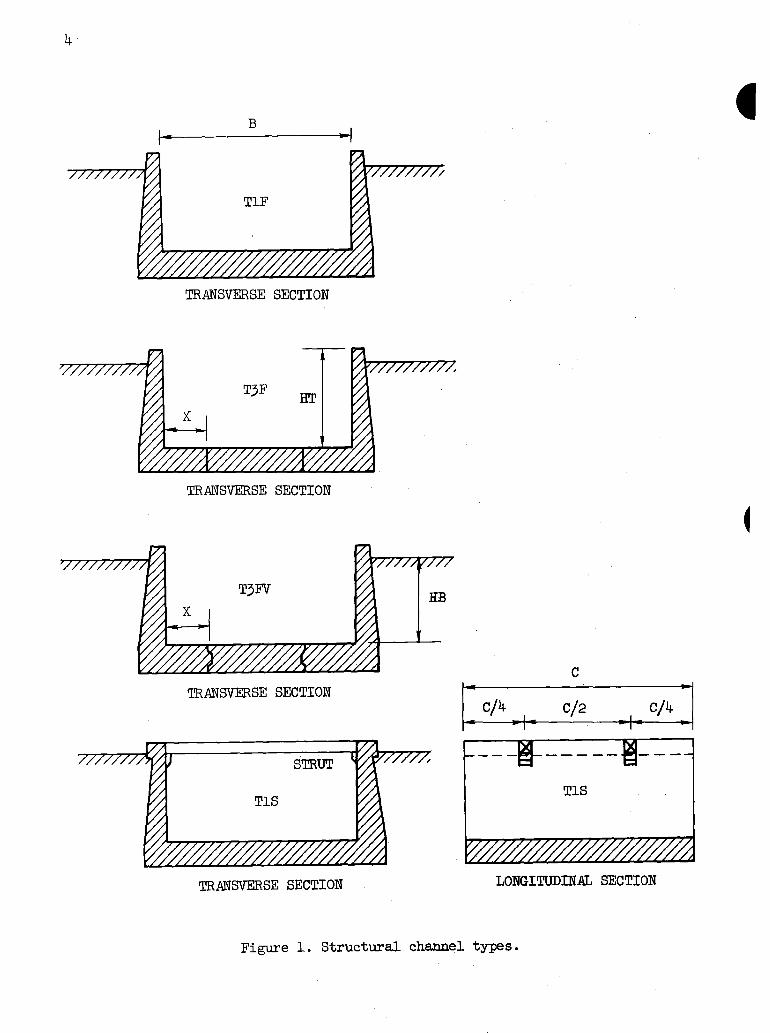
Four structural channel types are treated herein. All are assumed symmetrical about the channel centerline in both construction and load- ing. Each channel is designed for the two loading conditions described in the next section and each must satisfy flotation (uplift) require- ments. See Figure 1 for definition sketches. Any one of the four types ma.y be most advantageous for a particular set of design condi- tions. Because of the large number of parameters involved, it is not always readily apparent which type will be best in a given situation.
TLF Type In this type, the walls and floor slab constitute a reinforced concrete U-shaped rigid frame. The cantilever walls are integral with the floor slab.
Type T3F In this type, the walls are designed as reinforced concrete cantilever retaining wslls. The most advantageous toe length, X, is determined in the design. The pavement slab between the retaining wall bases, is independent of the bases except for any thrust imposed on it by the retaining wall bases.
Type T3FV This is similar to type T3F except that the joints between the pave- ment slab and the retaining wall bases are designed to transmit shear forces and the slab is monolithic between these two shear joints. Thus in type T3FV the pavement slab and retaining wall base deflect equally at the joints.
Type TlS This is similar to type TlF except that two reinforced concrete struts are provided in each longitudinal span between transverse joints. The struts are located at the first interior quarter points of the longi- tudinal span. Edge beams are provided along the tops of the channel walls. Thus the walls are not simple cantilevers from the base as with the other types, instead they are supported by the edge beam and strut system and by the floor slab.
Loading Conditions
Two loading conditions are considered in the design of structural channels. Parameter values should be selected so that these loading conditions reflect extremes of probable conditions.
Load Condition No. 1 In this loading the channel is empty. The backfill is submerged to a height, HWl, above the top of the floor slab. The backfill is naturally drained, i.e., moist, above HWl. Load condition No. 1 is meant to
Revised 7/77
TRANSVERSE SECTION
TRANSVERSE SECTION
TFUNSVEXSE SECTION C
TlS
TRANSVERSE SECTION LONGITUDINAL SECTION
Figure 1. Structural channel types.

5
represent conditions following a rapid lowering of the water surface in the channel, but before the water table in the backfill has lowered significantly from a high level. Thus this loading should maximize: lateral soil load, lateral water load, and uplift. The lateral pressure ratio, KOl, should be taken as high as can reasonably be expected. -
HT
r
f
uplift lateral lateral earth load earth load
Figure 2. Load condition No. 1.
Load Condition No. 2 In this loading the channel is full of water to the top of the wall and the backfill is submerged to a height, HW2, above the top of the floor slab. Load condition No. 2 is meant to represent conditions following a rapid raising of the water surface in the channel, but before the water table in the backfill has raised significantly from a low level. Thus this loading should minimize lateral soil load, lateral external water load, and uplift. The lateral pressure. ratio, K02, should be taken as low as can reasonably be expected.
l-
- - - -
ID HI3
‘
r //I///////
moist lateral
ftttttfti uplift
/n
buoyant lateral Llateral
earth load water load
Figure 3. Ioad condition No. 2.
6
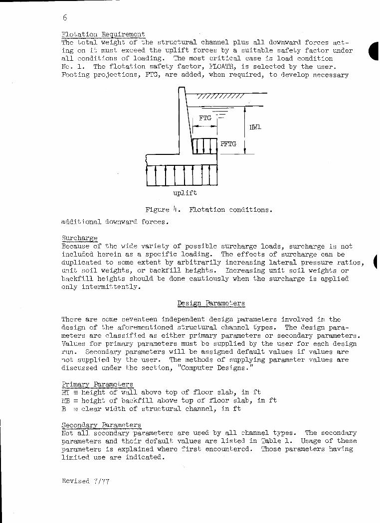
Fl_tation Requirement The total weight of the structural channel plus all downward forces act- ing on it must exceed the uplift forces by a suitable safety factor under all conditions of loading. The most critical case is load condition No. 1. The flotation safety factor, FLOATR, is selected by the user. Footing projections, FTG, are added, when required, to develop necessary
uplift
Figure 4. Flotation conditions.
additional downward forces.
Surcharge Because of the wide variety of possible surcharge loads, surcharge is not included herein as a specific loading. The effects of surcharge can be duplicated to some extent by arbitrarily increasing lateral pressure ratios, unit soil weights, or backfill heights. Increasing unit soil weights or backfill heights should be done cautiously when the surcharge is applied only intermitte.ntly.
Parameters Design ---
There are some seventeen independent design parameters involved in the design of the aforementioned structural channel types. The design para- meters are classified as either primary parameters or secondary parameters. Values for primary parameters must be supplied by the user for each design run. Secondary parameters will be assigned default values if values are not supplied by the user. The methods of supplying parameter values are discussed under the section, 'Computer Designs."
Primary Rarameters Y--w -e-3--.- HT E height of wall above top of floor slab, in ft RF3 E height of backfill above top of floor slab, in ft B z clear width of structural channel, in ft
Secondary Parameters ----- ---- Not all secondary parameters are used by all channel types. The secondary parameters and their default values are listed in Table 1. Usage of these parameters is explained where first encountered. Those parameters having limited use are indicated.
Revised 7’177

Parameter
Hwl tE submergence height above top of floor slab, load condition No. 1, in f-t Hw2 E submergence height above top of floor slab, load condition No. 2, in ft RWP = uplift head on pavement slab, load condition No, 1, in ft
Default Usage
o.am 0.X-B
T3F, T3FV
KOl - lateral earth pressure ratio, load condition No. 1 0.8 K02 = lateral earth pressure ratio, load condition No. 2 0.2 KPASS = passive earth pressure ratio l/K01 T3F
GMOIST = moist unit weight of backfill, in pcf GSAT E saturated unit weight of backfill, in pcf
120 140
FIOATR = safety factor against flotation 1.5 MAXFTG E maximum acceptable footing projection, in ft 0.5B JOIWE - longitudinal span between transverse joints, in ft * TlS
CFSC q coefficient of friction, soil to concrete CFSS = coefficient of friction, soil to soil
MFOUND 3 modulus of the foundation, in pcf
0.35 T3F 0.55 T3F
100,000"" TlF,TlS T3m
* when B 5 10 : JOINTS = 20
10 < B < 20 : JOINTS = 2B 9 2 BZ20: JOI.l!iTS = 40 t-J- if3
**note that a value MFOUND = 1 essentially produces a design corresponding to "rigid body mechanics," i.e. a uniform bearing pressure. 4 r; -4
,, ,, ,, ,. ,, ,, ,.,

8 .’
Design Criteria
Materials Class 4000 concrete and intermediate grade steel are assumed.
Working Stress Design Design of sections allowable-stresses
Extreme fiber
Shear, V/bD*
Flexural Bond
is in accordance with working stress methods. The in psi are
stress ti flexure f, =1600
v = 70
I_. tension top bars U = 3.411! f,'/D
other tension bars U = 4.8m/~
Steel in tension fs = 20,000 in compression, axially loaded columns f, = 16,000
Min3mum Slab,Thicknesses ‘WSUS
Bottom slabs 10 inches 11 inches
Temperature and Shrinkage Steel The minimum steel ratios are
for unexposed faces for exposed faces
pt = 0.001 pt = 0.002
Slabs more than 32 inches thick are taken as 32 inches.
Web Reinforcement The necessity of providing some type of stirrup or tie in the slabs be- cause of bending action is avoided by
(1) limiting the shear stress, as a measure of diagonal tension, - so that web steel is not required, and
(2) providing sufficient effective depth of sections so that : compression steel is not required for bending.
Cover for Reinforcement Steel ,cover is everywhere 2 inches except for outside steel in bottom slabs where cover is 3 inches.
Steel Required by Combined Bending Moment and Direct Force Required area determined as explained on pages 31 - 34 of TR-42, "Single Cell Rectangular Conduits - Criteria and Procedures for Structural Design."
Spacing Required by Flexursl Bond Spacing determined as explained on page 47 of TR-42.
Spacing of Reinforcement The maximum permissible spacing of any reinforcement is 18 inches.
*Shear sometimes critical at D from face, sometimes at face, see page 17 of TR-42.

9
Preliminary Designs
Trial concrete thicknesses are determined for various critical dimen- sions and preliminary concrete volumes are computed during the prelimin- ary design phase of structural channel design. These quantities may be increased during detail design if computations for required steel areas and spacings indicate thicknesses are inadequate. Assumptions, criteria, and procedures for the several channel types are discussed below. Topics applicable to more than one channel type are presented once when first encountered.
TlF Type Preliminary design of type TlF channels proceeds in an orderly manner. First, required wall thickness at the bottom of the wall, TB, is deter- mined. Then, the channel is checked for flotation and footing pro- jections, FIG, are provided if required. Finally, the floor slab thickness is increased for shear or bearing if necessary.
Wall thicknesses. set at 10 inches.
The wall thickness at the top of the wall, TT, is The thickness at the bottom of the wall, TB, is
selected as the largest thickness required by: shear for load condi- tion No. 1 (LC#l), moment and direct force for LC#l, shear for LC#2, or moment and direct force for LC#2. Illustrative computatations for a possible case of LC#l follow.
- KOl x GMOIST x HDIFF
Figure 5. Thickness TB for LC#l when HB > HWl.
Revised 7/77

10
Let HDIFF =HB - HWl For any effective depth, D, in inches, let
HwD=Hwl- D/12 HBJ)=H.fj- D/12
Then the shear, in lbs per ft, at D from face for case shown is:
v = 31.2 x (HWD)2 + KOl x GMOIST x HDIFF x (0.5 x HDIFF + HWD> + 0.5 x KOl x GBUOY x (HWD)2
where GBUOY = GSAT - 62.4 is the buoyant weight of the backfill, in pcf
so DE& ’ 70 x 12 = & An iterative process is required since the assumed D must agree with the computed required D. When the correct value of D is obtained, the thickness, T, at D from the face is
T = D f 2.5
and the thickness, TB, as required by shear is
TB = 10 + (T - lo) x HT/(EC - D/12).
The bending moment at the bottom of the wall is, in ft lbs per ft
H ~10.4 x (HWl)" + 0.5 x KOl x GMOIST x (HDSFF)2 x (HDIFF/3 -t HWl) + 0.5 x KOl x GMOIST x HDIFF x (HWl)2 + 0.5 x KOl x GBUOY x (I-lWl)"/3
The direct compressive force due to the wall, in lbs per ft, for a bottom thickness, TB, is
N=6.25xHTx (Tr+TB;)
The equivalent moment, Ms, is
MS = M + N x (0.5 x TB - 2.5)/12
So the required bottom thickness for balanced working stress conditions 5.S
m = (0.003683 x M~)I/~ + 2.5
An iterative process is again required since the assumed TB must agree with the computed required TB.
Computations are similar for LC#2. The largest required thickness con- trols.
Flotation. As previously noted, LC#l is critical with regard to flotation. For the case shown in Figure 6, the pressure, in psf, on the footing pro- jections is
PFTG = GMOIST x HDIFF + GSAT x DWl
the uplift pressure, in psf, for a floor slab thickness, TS, in inches, is
PUP = 62.4 x (Hw1 + TS/12)
the overall width of the channel, in ft, is
WO = B + 2(FTG + TB/12)

11
Hence the ratio, R, of the downward forces on the channel to the up- lift force is
R _ 2(N + PFTG x FIG) + 12.5 x TS x WO PUP x wo
where N = 6.25 x ITI x ('IT + TB). This ratio must not be less than the flotation safety factor, FIOATR.
The initial value of TS is TS = TB + 1 and the initial value of FTG is zero. If R < FLOATR, then FE is set at1.0, if again R -X FLOATR, then FTG is incremented by 0.2 ft and another attempt is made. This process is continued, if necessary, until FTG = MAXFTG, then TS is in- cremented by 1.0 inch until TS = TB + 10. If the flotation criteria is still unsatisfied, the design is abandoned, and a cancellation message is given.
Floor slab shear. Shear will sometimes govern the required thickness of the floor slab. For load condition No. 1 the compressive wall forces and the pressure on the footing projections are the only loads producing shear in the floor slab. The uniform loading, in psf, caus- ing shear is
PS = 2(N + PFI'G x l?C'G)/WO
The required floor slab thickness due to shear is obtained from an ex- pression for shear stress at D from the face of the wall, or using 3.5 inches as distance to center of steel
TS = (0.5 x PS x B)/(840 + pS/12) + 3.5
Occasionally LC#2 may be more critical than LC#l. The same expression may be used to obtain a required TS, however PFTG and ES must be re- computed for I#2 with PS taking account of the floor pressures due to the water in the channel. Thus
PS = 6214 x H'r - (62.4 x I-IT' x B + 2(N + PFI'G x FE))/WO.
If PS d 0, no further computations for TS are necessary since LC#l is the more critical.
Note that in the above expression for TS, from a theoretical viewpoint, 2.5 could sometimes be used instead of 3.5. To avoid confusion, 3.5 is always used to get these values of required TS for shear.
Figure 6. Flotation condition, IL!#l when HB > HWl.

Plk-~or slab bearing. As explained at the end of the section, "Detail De- -X, Floor Slab Analysis," it is sometimes necessary to increase the
floor slab thickness to eliminate negative displacements under the center of the floor slab. The theory involved is somewhat complex, its presen- tation is delayed until detail designs are discussed.
Revised 7177

13
Type The preliminary design of type T3F channels includes the design of many trial configurations. The toe length, X, varies from B/2 to Of The design having the least concrete volume is taken as best. Determina- tion of Tp and TB is the same as type TlF. For a particular value of X, the flotation requirements for the retaining wall portion is the same as type TlF, that is, if F is temporarily taken as B = 2X, the same relations apply. This provides an initial value for FTG. In type T3F designs, FTG is the heel length of the retaining wall base.
Base design. The maximum allowable bearing pressure, that is, contact or intergranular pressure, is taken as 2000 psf in excess of the inter- granular pressure that would exist at the elevation of the bottom of the base slab if the structural channel were not present. The line of action of the reaction (sum of all vertical forces including uplift) must lie within the middle third of the base. Each design for a parti- cular X must satisfy the above criteria. If this requirement is not satisfied with the initial value of l?TG, the footing projection is in- cremented and another trial is made. This is repeated, if necessary, up to FE = MAXFTG.
A possible case of LC#l is used for illustration. Let, in ft
HmFF=m-Hwl Hs = I3B + TS/12 Hw = HKl + TS/12 W = X + TB/12 + FTG
Then, in psf
PFTG = GMOISTx HDIFF +GSATx HWl PALIOW = 2000 + GMOIST x HDIFF + GBUOY x HW PUP = 62.4 x HW
The sum of the vertical forces in lbs per f-t, is
V-NET= N + F’FTG x l!TG + (12.5 x TS - PUP) x w
The overturning moment, in f-t lbs per ft,about 0 at the bottom of the toe
is M. = 10.4(HW)3 + 0.5 x KOl x GMOIST x (HDEFF>2 x (HDIFF/3 + 2.W)
+ 0.5 x KOl x GMOIST x HDIFF x (HW)2
+ 0.5 x KOl x GBUOY x (HW)~/~.
The resisting moment about the ssme moment center is
% = N x (x + (TT + m)/48) + PFIG x FTG x (w - 0.5 x FTG)
+ (12.5 x TS - ~LTP) x w2 x 0.5
Thus the distance from the end of the toe to VNET, in ft, is
Z = (M, -MO)/= If Z < W/2, the besring pressure, Pl is maximum. If Z > W/2, the bearing pressure, p2 is maximum.
*except that X may not exceed 40 ft
Revised 7/77

14
Now, in ft, the eccentricity of VNET, is
E =W/2 - Z
If [El > w/6, th e shape of the pressure diagram is unacceptable. If
F(1 + 6 x ]Ej/W) > PALLOW
the maximum bearing pressure is too high.
F =-!- HB -I
Hs FTG ,---I L- PFTG
Hw
I 0 * tttttr ttt’rttt PUP
TS
pl~~z: w,2
V-NET 1
m
P2
Figure 7. Bearing pressures, iX#l when HB > HWl.

15
When bearing and pressure distribution requirements are satisfied, base thicknesses required for shear are determined. For IC#l, shear is in- vestigated in the toe at distance D from the face of the support and in the heel at the face of the support. Several situations are possi- ble in determining shear in the toe at D from the wall. Figure 8 illus- trates one possibility in which X > D and Z < W/2.
W 4 w X
. r
Pl
I
Figure 8. Investigation of footing shears.
Now D = TS - 3.5 xD=x- D/l2 Y-D =w/2 - XD
Then, in psf
Pl = F(l + 6 x E/W)
l?D= y(l + 12 x E x YD/(W x W))
So the shear, in lbs per ft, at D from the face is
VD = (0.5 m + m) + m - 12.5 x TS) X XII

16
To get the shear in the heel at the face of the support, let
xl? then
m then
P2 and
PF
so VI?
The required
TS and
TS If either of accordingly.,
= x + !cB/12 *
=w/2 -xl?
= F(1 - 6 x E/W)
= yql + 12 x ExYF/(WxW))
= (PFTG + 12.5 x TS - PUP - 0.5(1?2 + PF)) X m
thicknesses for these shears are
= v11/840 + 3.5
= 1~1840 + 2.5 these values exceeds the current TS, it is increased
Computations are similar for LC#2. The water in the channel must be included in obtaining VNET and the resultant moments. Shears are in- vestigated in the toe at the face of the support and in the heel at D from the face of the support.
Bxement slab thickness. In type T3F channels, the pavement slab is independent of the retaining wall portions of the channel. The pave- ment slab must therefore satisfy flotation requirements independently. The uplift head on the pavement slab is RWP. The uplift head could have been made a function of IiWl, the same as for the retaining waJ-1 portions. However, it was felt that it should be possible to take account of drainage systems, etc. that might be built into the pavement. Mote that RWP is measured from the bottom of the pavement slab, not from the top of the slab as is the case with RWl and RW2. Thus the re- quired thickness of the pavement slab to satisfy flotation requirements is, in inches,
TP = 62.4 x RWP x FLCATR/12.5
l-l n
J t ttm--- 62.4 mP
Figure 9. Pavement slab flotation, type T3F.

Type T3FV 17
The preliminary design of each type T3FV channel for a particular toe length, X, is similar to that for type T3F channels with one important exception. The joint between the pavement slab and the retaining wall base is designed to transmit shear from one structural. component to the other. Thus the pavement slab and the retaining wall base are forced to deflect equaUy at the joint. Note that the joint is structur- dly a hinge, that is, it will transmit shears and direct forces, but not moments.
Determination of joint shear. An expression giving the shear trans- mitted through the joint may be obtained by equating expressions for the vertical displacement of the pavement slab, 8
a9; at the joint and
for the vertical displacement of the retaining w base, s, at the joint. It is assumed that such vertical displacements are equal to the intergranular bearing pressure (contact pressure) divided by the modulus of the foundation, that is
where 6 - = P MF@JTm z
vertical displacement, in ft intergranular bearing pressure, in psf modulus of foundation, in pcf
Equating 6 and 8b, note that the term for the modulus of the foundation cancels ou , t and
F, = pp
~~yIy--zI-j&~
Figure 10. Joint shears in Type T3FV channels.
The pressure Pp, in psf, may be considered as that due to to any other loads on the pavement slab. . . . . If the pavement
Q plus that due slab is treated
as a "rigid body," the pressure due to Q is 2Q/XP. This leads to compu- ted values of Q that are larger than actual values. If the pavement slab is treated as an "elastic body," the pressure due to Q is Qh, where A. is given below. See "Floor Slab Analysis," pages 33 - 38 for development of similar theory and definition of terms.
x = 2f3(CoSh pi + 'OS @') in per ft sinh f31 + sin g1 '
B = (518’+ x K/(E x (TP)">l14 , in per ft
01 = f3 x XP

Cintergranular bearing pressures
MC _ Q(W/2>(W/2) _ 3Q I (wj3/12 w
2Qh
Base pressures concerned with joint shears.
Thus Pp = Qh + WP
where WP = pavement slab bearing pressure at shear joint, in psf.
Similarly, the pressure Pb may be thought of in two parts, that due to Q and that due to other loads. From Figure 11, noting that Pl may be obtained from relations described with type T3F
Pb = P1 - 4Q/W
Thus equating bearing pressures at the shear joint
Qh + WP = Pl - 4Q/W or7 in lbs per ft
Q = (Pl - WPk--&y)
This expression for Q may be thought of in two rather different ways. First, as presented, in which Pl and WP are independent of Q, so that the value of Q obtained from the expression is the true, total value of Q transmitted across the joint. Alternately, if Pl and WP are computed for loads which include an assumed value of Q, the value of Q obtained from the expression is the additional, or LQ required to produce equal vertical displacements. Both concepts are used in the design of type T3FV channels.
Revised 7/77

19
Design approach. Determination of TT and TB is the same as type TlF. For each value of X, the design cycles,starting with initial values of Q,l and Q2 (for LC#l and LC#2) set equal to zero and continuing until the design stabilizes at constant values of FTG, TS, TP, Q,l, and Q2. That is, for Q,l = Q,2 = 0, the design obtains the required FIG, TS, and TP. Then new Ql and Q2 are computed using the just determined dimen- sions, next new vslues of FIG, TS, and TP are obtained. Then new Q,l and Q,2 vsLLues are computed, etc. The design usually quickly converges to correct values.
Wall base flotation. The WELL base flotation is treated separately from pavement slab flotation, but each must account for Q,l. Refering to Figure 6 and the flotation expressions under type TlF and letting B be taken temporarily as B = 2X, if QJ acts upward on the wall base then
R = 2 x (N + PFTG x FIG) + 12.5 x TS x WG RTPxWO+2xQl
if Ql is negative, that is, acts downward on the wall base then
R =~X(N+PFIGX~)+~~.~XTSXWO-2xa
IUPXWO
R can not be less than FLOATR. Thus a minimum value of FIG corres- ponding to the current value of Ql may be obtained.
Base design. Base design of type T3FV is the same as type T3F except that the appropriate shear, Ql or 62, must be included at the end of the toe. Thus loads is
Similarly, the of the support
VD=
for IC#l, the expression for the sum of the vertical
= N + PFIG x FTG + (12.5 x TS - PUP) x w - Q,l
expression for shear in the toe slab at D from the face is
(0.5(= +
Pavement slab thickness. In type T3FV channels, the thickness may be governed by flotation or by shear due to the joint shear.
QJI XP
m) + pup - 12.5 x TS) x ~0 + a
TP
62.4 x HWP
Figure 12. Pavement slab flotation, type VFV.
20
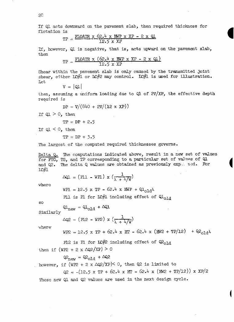
If Ql acts downward on the pavement slab, then required thickness for flotation is
TP=FLOATRx 62.4 x HWPX XP - 2 x QJ 12.5 x XP
If, however, Ql is negative, that is, acts upward on the pavement slab, then
TP = FIOATR x (62.4 x HWP x XP - 2 x Ql) 12.5 x XP
Shear within the pavement slab is only caused by the transmitted joint shear, either I&& or LC#2 may control. LC#l is used for illustration. Let
v = b-l then, assuming a uniform loading due to Ql of 2V/XP, the effective depth required is
DP = v/(840 + 2v/(12 x XP))
If Ql > 0, then
TP = DP + 2.5
If Ql < 0, then
TP = DP + 3.5
The largest of the computed required thicknesses governs.
The computations indicated above, result in a new set of values Delta Q. for l?TG, TS, and TP corresponding to a particular set of values of Ql ala Q2. The delta Q values are obtained as previously exp...- r,,zd. For E#l
where
so
Similarly
where'
NJ- = (Pll -wPl> x(&J
WPl = 12.5 x TP - 62.4 x HWP + Ql,ldX
Fll is Pl for LC#l including effect of Q,l,ld
new = aold + m
nQ2 =(P12 -WE) x( T-h+
wp2 = 12.5 x TP + 62.4 x RT - 62.4 x (HW2 + TP/12) + Q2,ldX
PI-2 is Pl for IC#2 including effect of Q2old
then if (WP2 -I- 2 x &2/XP) > 0
QZlew = &2,ld + 42
however, if (WE2 + 2 x DQ2/XP)< 0, then Q2 is limited to
Q2 = -(l2,5 x TP + 62.4 x EC - 62.4 x (HW2 I- TP/12)) x XP/2
These new QL and Q,2 values are used in the next design cycle.

21
Ty-pe TX3 The design of type TlS channels is considerably more complex than any of the Drevious channel types presented. One of the problems involves the determination of the magnitude and distribution vided the walls by the edge beams. Strut locations
of the support pro- were selected at
Figure 13. Definition sketch, type TX3 channel.
the indicated quarter points of the longitudinal span between trans- verse channel joints for two reasons. The spacing is architecturally pleasing since the result is equally spaced struts in a long channel. Such spacing causes a considerable reduction in the maximum moments and shears that exist in the edge beams as compared to those that woCLd exist if the struts were placed at the ends of the longitudinal spans. The struts require positive connections to the walls to prevent acci- dental dislodgement from the supporting'wall brackets and because often the strut force will be direct tension rather than direct compression.

22
Figure 14. Possible strut-to-wall connections.
The wall bracket itself may be designed to prevent lateral movement of the struts.
Edge beam analyses. Before proceeding with the preliminary design, the edge beam theory is established. Load is brought to the edge beam by the vertical wsJ.l. The magnitude of this load, Rx, varies from section to section along the wsll. The struts provide the necessary edge beam reactions. The immediate problem is to describe and evaluate the load- ing on the edge beam. This may be accomplished by considering the frame
i-Y
FIX, lbs per ft
of edge beam
Figure 15. Edge beam loading and displacement.
displacements occuring at a typic& vertical section in the channel.
-Rx
Figure 16. Type TlS frame displacements, typical loading.

23
The displacement at the top of the frame is Y = T - U x RX where
Y = displacement at to@ of frame, also displacement of the edge beam, in f't
T 3 displacement at top of frame with struts removed, in ft
U = displacement at top of frame due to unit horizontal loads at top of frsme, in ft per lb per ft
RX = frame reaction provided by edge beam, also load on edge beam due to frame loading, in lbs per ft.
Thus RX = T/U - Y/U
or RX=m-nY
where m= T/U and n =1/U
The frame constants, T, U, m, and n depend on the structursl channel dimensions and loading. They are readily determined when needed.'
The elastic curve equation for the edge beam is
EId* -=m=m-nY dx4
or letting 4p4 = n/E1
then d% dx4
+ 4Sdy = m/E1
The general solution could be written and the constants of integra- tion evaluated by applying various boundary conditions. This becomes rather involved and prone to error because of the interior location of the struts.
The above procedure can be avoided by utilizing a method of solution indicated on pages 15 - 17 of Timoshenko's "Strength of Materials, Psrt II," for the somewhat similar problem shown in Figure 17.
RS Rs
Figure 17. Alternate method of solution for edge beam analyses.

24
Let
@(@Z) = e"' (cos /3Z + sin BZ)
Jr(f3Z) = e+'(cos f3Z - sin SZ)
@(@Z) = e+' cos f5Z
[(@Z) = e"' sin @Z
Then solve for Q. and M. from the simultaneous equations QQ J-g l+Jr(BC) + Q” -- 2 r 1’ ‘1 - @(PC) $4 + eLy+ g [yPc/4:
-- 1- @(PC) + F
+ W4)\= o
9( 3@C/4) + e(pc/4) = 0
Raving $ and I$,, then for any Z, the deflection YZ, is
n
This expression ing on a finite that where
m), = c/4
L J finds the deflections due to symmetrical loads, RS, act- length beam. To convert to the edge beam problem note = 0, or let YX = YZ - Y.
yo = w [l + ~W2)]+ g pc/4) -!- 0(3&4)]
+ y$PC/4) + 5(3PC/4)]
The sign of the deflections must also be changed to agree with the coordin- ate orientation shown in Figure 15. Thus
yx = - (YZ - Y,) = Y. - YZ
The process of obtaining the magnitude and distribution of RX and of obtaining the magnitude of RS proceeds by trial as follows:
Let RXaver = m, that is, assume YXaver = 0
Then RS = RX,,,, x C/2
Evaluate YX, due to RS, at a large number of points Compute new YXaver, RX,,,, = m - nYXaver, and RS
Repeat this process until RS is essentially constant from one cycle to the next. When constant RS is obtained, compute RX corresponding to each YX, that is,
FX=m-nYX

25
Design approach. As with most statically indeterminate systems, sizes and dimensions must be known or assumed before the system can be ana- lyzed. Thus an initial set of trial dimensions is needed. Values for this initial set could simply be guessed, or some approximate methods could be used to obtain them. The latter is used herein. However, the approximations are not discussed separately here since what is more important is an understanding of a typical design cycle or iteration.
Design cycles are repeated as often as necessary to obtain a stable set of dimensions. Each cycle uses current forces to obtain new dimen- sions from which new forces are computed, etc., repeatedly. One design cycle is described below, assuming a set of trial dimensions is already available.
Edge beam loading. The first step in obtainin RX and RS values is to evaluate U and n = l/U, in ft per lb/ft and lb 7 ft per ft respectively. These vslues depend solely on the dimensions of the frame. U is com- puted as
FRAME $3TtAME +AME
I \ -L -1 -
I
,J
T
I a
I
-A\ L B
c .- -I-- TB
n
I
I-+M I
Figure 18. Evaluation of frame U and n.
where E z modulus of elasticity of concrete, in psf y 3 distance from mid-support of frame, in f't t q thickness at y, in ft As = incremental length along axis of frame, in ft
Next, T and m = T/U in ft and lbs per ft are computed. T is computed as
PFRAME
where the 'terms are as previously defined and
M = average moment over the length &, in ft lbs per ft
LC#2 is used for illustration. LC#l is similar, but without the effects

26
of water in the channel. Figure 19 indicates the vertical forces in- volved. The struts have been removed, but their effective weight is included in the force NWALL.
@
FGR
I W/2
Figure 19. Vertical forces involved with frame
This force, in lbs per ft, is
T and m, IC#2 when RR > RW2.
lYWALL = 150 x B x ST x SB/( 144 x C) + 150 x (ET - TT) x EB/144
and here + 6.25 x HT x (TT + TB)
PFTG =GMOISTx HDIFF + GSATx HW2
so that FGR, which includes uplift, in psf, is
ER = (2 X (NbmL + mG X m) + 124 X Ts X w
+ 62.4 x HT x B)/W - 12.5 x TS
The summation for T over the w&L1 portion of the frame is readily made. Wall moments due to external lateral loads produce a positive displace- ment, T, while wall moments due to internal water produce a negative displacement. The components of loads and moments involved in the summation for T over the floor portion of the frame are indicated in Figure 20. The summation may be said to include only the clear distance B/2 since I is assumed to approach infinity at the joints.
A concentrated moment is brought to the floor slab at the junction of wall stem and footing projection. This moment, MC, is the sum of two moments MWALL and MF'TG. NULL is the moment due to the loads acting on the wall stem. MFTG is due to the loads on the footing projection

27
and is
M’FI’G = 0.5 x FGR x (FTC + T~/24)~ - l?l?TG x FIiG x 0.5 x (FTG + TB/12)
With reference to Figure 20, the summation for one half of the floor
Tf = (12/E) x (MC - MR -I- 2 x (MW - Ml3)/3) x (H.R + TS/24) x 0.5 x B/(TS/12)e
where moments are in ft lbs per f't and other terms are as previously defined. Thus the frame displacement constants, ml for lX#l, m2 for L&k?, and n are determined. -
TS 5
' MC=MWAJX, 3 +MFTG
MBP = i/8 x FGR x (BFGR)~
MB =1/8 x PGR x B2 BflR = B + TB/l2
Mw 2
A MR=Mlw-MB
MBP Ml3 li )
I t
Figure 20. Floor slab loads and moments for frame T and m.
With the frame constants known, the edge beam loadings, RX, and the strut forces, RS, can be computed for LC#l and L&k? as outlined at the end of the section, "Edge beam analysis." In these computations the stiffness of the edge beam is reflected by the term p which is, per ft
B = (&I l/4 114
= 12( 3n
ExEBx(ET)" 1
RX values are found for a large but finite number of points along the edge beam span. The signs of RXL and RX2 are adjusted so that a posi- tive RX has the meaning shown in Figure 21. It is possible to have values of RXL, RSl, RX2, and RS2 of either sense, that is, positive or negative.

28
Figure 21. Sense of positive edge beam loading.
Strut design. With the edge beam loading known, the preliminary design can proceed with the determination of a new set of dimensions. The Y strut is the first unit re-evaluated.
The strut must be designed to carry direct tension if either strut re- action RSl or RS2 is tensile. Let RT, in lbs, be the larger of any such tensile reaction. Then the required tension steel area, in sq inches, is
ATENS = RT/20,000
Minimum values for the strut dimensions, in inches, are
ST = B/20 for deflections control in accordance with AC1 909(b)
SB = B/50 for lateral support in accordance with AC1 908
Also, neither ST nor SB will be taken less than 12 inches, which more than satisfies AC1 912.
The strut must be capable of carrying the maximum compressive strut reaction, let this be RC, in lbs. In addition to RC, the strut carries its own dead weight in bending about the horizontal cross sectional axis of the strut. The process of compressive design is thus as follows.
Set SB & ST at minimum values. Get dead load moment, in ft lbs:
MD = 0.125 x (150 x ST x SB/144) x B x B
Get eccentricity of RC due to MD, in inches
E =12 x MD/RC
Get correction for long column by AC1 Eq. (9-3)
Rx =1.07 - 0.008 X (12 X B)/(O.3 X ST) Il.0 =1.07 - 0.32 x B/ST 5 1.0
Get direct compression for short column
Take
Take
NX = RC/m
RX, see page 32 of TR-42, as larger of
Nx or RX x 0.64 x (l..+ 4 x E/ST)
compressive steel area, ACOMP, in sq inches, as larger of
ATENS or 0.01 x ST x SB, in accordance with AC1 913(a)

29
Find required gross area of column, AGX in sq inches, from AC1 Eq. (14-l) and AC1 1403
+GX = (NX - 13600 x ACOMP)/~~O
Get correction for long columns
RY = 1.07 - 0.32 x B/SB 5 1.0
Get direct compression for short columns
NY = RC/RY
Find required gross area of column
AGY = (NY - 13600 x ACOMP)/850
Let AG = ST x SB in sq inches If AGX, or AGY, or both, are greater than AG, then ST, or SB,
or both are incremented accordingly and the cycle is re- peated until both AGX and AGY are s AG.
Wge beam design. The thickness of the edge beam is established by the requirements for bending moment. This is done on the assumption that web steel for diagonal tension will be provided when necessary. It should be noted that the edge beam is subjected to unknown amounts of torsion. Hence nominal closed stirrups (say #3 @ 12) should be provided even when diagonal tension web steel is not required. Thicknesses re- quired for bending moment are determined at the centerline of the sup- port since moments at midspan are small by construction. A summation
-I-- l I - \ I 1
ST
EB Z ST Er52xEB mZTT+2
Figure 22. Edge beam section.
process is used to obtain the various shears and moments of interest because the loading curves assume various shapes.
30
Initially EB is set equal to ST. The maximum thickness required for bending is determined. If ET, so obtained, is more than twice EB, EB is incremented and another solution is made for ET. Next the maximum thickness which would be required for shear, assuming no web steel, is computed. If this thickness is more than that required for bending, web steel is required. Required web steel is calculated during detail design. Shears are investigated both left and right of the centerline of the support. When the strut reaction is compressive, shears are assumed critical at D from the faces of the support. When the strut reaction is tensile, shears immediately adjacent to the centerline are assumed critical.
Wall design. The wall must be designed for the most critic&L conditions that exist at any section along the wall between transverse channel joints. As noted, the edge beam provides a variable support to the well. In order to control the most critical loadings on the wsll during design, the maximum and minimum RX values are found for each load condition. These are RXLMAX, RXlMIN, RX2MAX, and RX2MIN respectively. Required wall thicknesses are found for shear at the-top of the wall just below the edge beam, shear at the bottom of the wall, and moment at the bottom of the wall. Moment nesr midheight of the wall, of opposite sign to the moment at the bottom of the wsJ.l, often exists but is usually of smaller magnitude than the moment at the bottom.
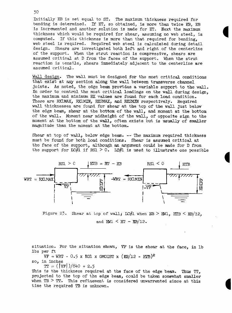
Shear at top of wall, below edge beam. -- The maximum required thickness must be found for both load conditions. Shear is assumed critical at the face of the support, although an argument could be made for D from the support for LC#l if RSl > 0. LC#l is used to illustrate one possible
WRT
RSl > 0 -E--m RSl < 0 1 HTB
Figure 23. Shear at top of wall; LC#l when HE3 > HWl, WB < EB/12,
and RWl < HT - EB/12.
situation. For the situation shown, VE is the shear at the face, in lb lbs per ft
Vl?=WRT- 0.5 x KOl x GMOIST x (EE3/12 - HTB)2 in inches
"' TT = (lvF/ l/840 + 2.5 This is the thickness required at the face of the edge beam. Thus TT, projected to the top of the edge beam, could be taken somewhat smaller when TB > TT. This refinement is considered unwarrented since at this time the required TB is unknown.

31
Shear at bottom of well. -- Shear is critical at D from the face of the support for LC#l and at the face for LC#2. Since the shear at bottom of the wall is to be maximized, the wall reaction at the top, WRT, is set equal to the minimum edge beam loading. LC#l is used for illustration.
RSl > 0 RSl < 0 WRT = RXlMIN r -WRT = FCUMIN
4
/////////
\
-
Figure 24. Shear and moment at bottom of wall, Lc#l when HB > RWl.
Computations and iterative process are similar to those explained for thickness TB for type TlF channels with the addition of WRT. The shear at D from the face is
V = 31.2 x (RWD)2 + KOl x GMOIST x BDIFF x (0.5 x HDIX'F + J34-D)
+ 0.5 x KOl x GBUOY x (RWD)2 - WRT then
D = v/840
and, when computed and assumed D values agree
T = D + 2.5 so
TB = 'IT + (T - IT) x RT/(RT - D/12)
Moment at bottom of wall. -- Moment at the bottom of the wall is maxi- mized by using the smallest well reaction at the top, hence Figure 24 applies.
The moment expression for LC#l for the situation shown is the same as for type TlF with the addition of the WRT term, thus
M = 10.4 x (HWl)e +0.'3 x KOl x GMOIST x (RDIFF)2 x (RDIFF/3 + HWl) +0.5 x KOl x GMOIST x RDIFFax (HWl)2 +0.3TxxKOI-I-x GBUOY x (RWl) /3
- EB/24)
The direct compressive force is NWALD as given under "Edge beam load- ing." The equivalent moment, Ms., thus is
MS = M + mm X (0.5 X m - 2.5)/12
32
The iterative process for TB then proceeds as explained for type TlF channels.
Flotation requirements and floor slab shear. Required footing projec- tions, FTG, and required floor slab thickness, TS, are obtained as ex- plained for type TlF channels with the substitution of NWALL for N to account for the weights of the struts and edge beams.
Floor slab bearing. It is sometimes necessary to increase the floor slab thickness to eliminate negative displacements under the center of the floor slab. The theory is presented in the following section, "Detail De- signs, Floor Slab Analysis."
Revised 7/77

33
Detail Designs
With the exception of the steel in the edge beams of type TlS channels, detail design is concerned with the determination of requirements for transverse steel, not longitudinal steel.
.Zach detail design begins with the set of trial dimensions obtained in the preliminary design. Thicknesses are incremented, and the design recycled when necessary, whenever it is determined compression steel would otherwise be required to hold bending stresses to allowable work- ing values. Required steel area and maximum allowable steel spacing are computed at a large number of points in the channel cross section. The points are similarly located and numbered in each structural channel type so that there is little difficulty in changing thought from one type to another. Schematic steel layouts are shown for each type. The actual steel layout is selected by the designer once he knows the steel requirements at the various points. The floor slab steel requirements for type TlF and TlS channels are based on analysis of the floor slab as a symmetrically loaded, finite length beam on an elastic foundation. This theory is presented before discussing the detail design of the four channel types.
Floor Slab Analysis A means of determining the deflection, shear, and moment at any point, A, in the slab is required. This may be done by starting with the elastic curve equation /
d% EIz= P= -KY
or letting
4P4 = K/E1
then
d% ax4
+ 48% = 0
where
K ~&fjjY)m=
E s
P s
I s
B z
TS = -
modulus of foundation, in pcf
modulus of elasticity of concrete, in psf
foundation pressure, in psf
moment of inertia, in f-t4 per ft
(5184 x K/(E x (TS)e))li4, in per ft
floor slab thickness, in inches
The modulus of the foundation, MFOUND, is also known by such names as: coefficient of subgrade reaction, subgrade modulus, coefficient of settlement, and modulus of subgrade reaction. Rather than work through the solution of the differential equation, it is easier to utilize various known solutions for infinite beams and to obtain the desired results by superposition. In Figure 25, solutions for (a) and (b) may be obtained by the procedure previously presented for the edge beam analysis. Loadings (c) and (d) require further development.

L
PF oW Mw PB
lllll-ttttrtttt 9
//////////i/"/i/// - I Z
A"""""""i"fi'
NW NW
Y \’
Mw d-4
Mw h
PF
IllIll
PF
IllIll
(4
PB
ltttttttttl
Cd)
A.- TS
Figure 25. Finite length beam and loadings.
Deflection, shear, and moment due to NW. Expressions for deflection, shear. and moment are needed when the point A assumes various loca- tions: Let YA, VA, and MA be these quktities in ft, lbs per ft, and ft lbs per ft respectively.

35
When A is at the left end of the beam, i.e. Z = 0
YA = m+p(,J) + @(@CL - J1j-j
VA = F E(BJ) + e(p{L - J)g
MA=g C ‘@J) + ‘I’btL - JIU
When A is between the left end of the beam and the load, i.e., OSZSJ
YA = w p(B(J - Z)) + 0(B(L - J - Z)jj
VA = F e(@{J - Z)> + e(B{L - J - Z)fl C
MA+ C ‘i’(BtJ - Z,) -I- '/'(@CL - J - z1g
When A is between the two loads, i.e., J 5 Z 5 (L - J)
YA = w E(@{Z - J)) + @(@{L - J - ZI,1
VA = B E O(B(Z - J)) + e(p{L - J - Z))]
MA = g k(B(Z - Z,> + ‘@EL - J - Z]q
Deflection, shear, and moment due to MW. Expressions for deflection, shear, and moment due to the moment, MW, brought to the floor slab by the wall follow.
When Z =0
YA = _ v [((BJ) - S(BiL - Jl,l
VA = 0 m+ &BJ) - @(B{L - J?]
MA = - F &@J) - Q(PFL - Jlfl
When OlZlJ
YA = - + E(B(J - Z)> - C(B(L - J - Z)?j
VA = - v E(P(J - Z)> - @(B(L - J - Z)g
MA= - F @B(J - Z)> - e(B{L - J - Z)jj
When JrZs(L-J)
YA = v [${Z - Jl> + [(DEL - J - ZCJ

36
VA = - w+ p(P(Z - J>> - @(B(L - J - zl)]
MA = F @(B(z - J>> -I- @(@IL - J - z}g
Deflection, shear, and moment due to uniform loading, g. Before terms for the uniform loadings PB and PF can be obtained, solutions for uni- form loads must be established. These are obtained by integrating the corresponding expressions for a concentrated load. Refer to Timoshenko, pages 6 and 7 for similar material.
Without proof:
s e(fddX = - $ Jr(f3X)
s S(BX)dx = - $ @W
J @(@X)dx = - ; Wx)
J 'k(PX)dX = +; r;(r,X>
Figure 26. Uniform loading cases, infinite beams.
When A is to left of loading, noting that dN = qdX b a
YA = E @(BX)dX = 2 E(pa) - e(gb))
similarly
When A is within the loading
37
When A is to be the right of loading
Expressions for deflection, shear, and moment due to FT3 and F'F can be found from the above terms upon correct substitution of F'B, PF, L, J, and Z for q, a, b, c, and e.
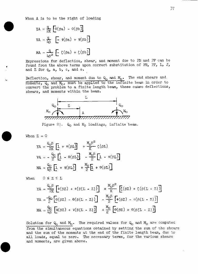
Deflection, shear, and moment due to Q, and Mo. The end shears end
moments, Qo and % must be applied to the infinite beam in order to convert the problem to a finite length beam, these cause deflections, shears, and moments within the beam.
L
Qo
M, A %I , ////////////x//////////////////////
Figure 27. Q. and M. loadings, infinite beam.
When Z =O
YA =g E + @(SLjj +g HBL)
VA = - 3 fi - 8(SLjj - yp - @(S~fl
MA+ E + MJ + $)k + WL)]
When OSZSL
YA = g k(W) + @CL - zig + F &BZ) + ~(S(L - z}]
VA =-$ e(P) - 0(@(L - [: zl)] - y E(@Z) - WL - Zlfl
MA = $ E(w) + HB{L - Z}YJ M,
+ 2 rpz) + @(@CL - z}g
Solution for $ and Mo. The required values for Q. and M. are computed
from the simultaneous equations obtained by setting the sum of the shears and the sum of the moments at the end of the finite length beam, due to all loads, equal to zero. The necessary terms, for the various shears and moments, are given above.

38
Solution for finite beam. With Q. and M. known, expressions for the de- flection, shear, and moment may be written for any point, A, in the beam. Different expressions will result depending on whether 0 5 Z 5 J or J5 Zs (L - J). As one example, the expression for moment, in ft lbs per ft, at A when Z > J is
Qc MA = 48 k(m) + 4wIJ - zl jl
M, + y- [Ie(PZ) + @(ia - zl)]
+g C IJWZ - J>> + Jr(BiL - J - zlj
+ 7 E(P( Z - Jl> + @@IL - J - Z)a
+ s[C(B(z - J,) + C(B{L - J - Zljj
PF + ,,[-!tbIZ - Jl) + t=(BZj
F!F -I- -
4P2 C -5(@{L - J - .U> + ((@CL - ZliJ
fiTTote that a host of problems, in addition to the immediate one of channel floor slab, can be solved by this procedure, e.g., combined footings.
J' l--l NW’ Mw’
43 L'
i-L Figure 28. Corrections for indicated tensile reactions.

Sometimes negative deflections, indicating tensile reactive pressures, are encountered. If this occurs, the solution is considered incorrect since this technical release is meant for structural channels on yield- ing foundations and tensile bearing pressures can not exist with earth foundations. Negative deflections may occur at either the ends of the beam or at and near the center of the channel.
If negative deflections are encountered at the ends of the beam, a correct solution is obtained by modifying the effective loading and dimensions of the finite length beam as indicated in Figure 28. Assume a solution is attempted, then let the distance from the end of the beam to the point of zero reactive pressure be ZOOS. If ZPOS = 0, the solu- tion is correct. If 0 < ZOOS 5 J, add the cantilever shear and moment, QSUP and MSUP, to the system. Change J to J', and L to L'. Solve this beam for a new ZPOS. If ZPCS > J, change IW to NW', MW to MM', J to 0.0 and L to L'. NW' and MW' are the statical cantilever equivalents of the forces and moments within the distance ZOOS. Solve this beam for a new ZPQS. The next solution will yield another ZPOS, etc. ZOOS values so found, will approach zero, that is, the series is convergent and may be stopped when desired.
If negative deflections sre encountered at and near the center of the channel, a correct solution can be obtained by increasing the weight and stiffness of the floor slab so that negative displacements are eliminated.* Therefore, when the analysis indicates tensile bearing pres- sures under the center of the channel, the slab thickness is incremented and a new, smaller required footing width is determined corresponding to the incremented slab thickness. The design is then recycled using the new TS and FTG. This check and subsequent recycling, when necessary, occur during preliminary design of type TlF and TlS channels. The srob- lem is usually only encountered with relatively wide channels.
*An alternate approach to obtaining a solution for TlF and TlS floor -- ---
slabs, when negative center displacements are encountered, is to revert to "rigid body mechanics." That is, assume the floor slab is a rigid beam subjected to uniform distribution of bearing pressure, rather than an elastic beam. This can be done by using a very low value of MFOUND as MFOUND = 1. Structurally, the assumption of uni- form bearing results in larger center moments than any other ad- missible distribution of bearing for these slabs. Some reasons why "rigid body mechanics" is often not the best approach are:
a. It may result in a greater slab thickness than is re- quired by elastic theory.
b. It will result in a greater steel requirement than is required by elastic theory.
C. It may cause moment of opposite sign to the maximum moment to be missed. Elastic theory often shows the existance of such moments near the ends of the span.
d. It does not produce positive contact between floor slab and foundation at sll points.
If "rigid body mechanics" is used, detail designs rather than preliminary designs should be run. This is true because the slab thickness must often be increased during detail design to hold bending stresses to allowable limits.
Revised 7/77

42
then vz = vl + v2 + v3 + v4
and, in ft lbs per ft MZ=Vlx(BDIFF/3+Z-HIV)
+ v2 x (z - HTw)/2 +(v3 + v4) x (z - inw>/3
also, in lbs per f't NZ = 6.25 x z x (TT + T)
HDIFF
I NZ
Figure 30. Wall steel design for Lc#l,+HB > HWl, and Z > HTW.
The required steel area for this MZ and NZ may be obtained as explained in T'R-42. If the current effective depth is inadequate without using com- pression steel, the bottom thickness, TB, is incremented and the wall steel design is begun again. This process is repeated, as necessary, until TB exceeds its original value by 10 inches. When the effective depth is ade- quate, the required maximum allowable spacing, in inches, is given by
sz do,015 x (T - 2.5)/vz
as explained in TH-42.
Floor slab steel. The floor slab analysis developed earlier is used to obtain shear and moment values from which steel requirements are deter- mined at the various points in the slab. Either LC#l or LC#2 may govern the steel at a particular point. One case of IC#l is used to illustrate the computation of the load components on the floor slab.
The vertical wall loading, in lbs per ft, is
NW=~.~~XHTX(TT+TB)

43
The various horizontal components of loading on the wall, in lbs per ft, are
Hl = 0.5 x GMOIST x KC1 x @DEE')'
H2 =GMOISTx KOlx HDIFFx HWl
II-3 = 0.5 x GBUOY x KOl x (RWl)"
H4 = 0.5 x 62.4 x (mj2
the tot&l. horizontal loading on the wall is
The moment
MW= + +
The direct is
CF = + t
The direct per ft, is
CB =
brought to the floor slab by
HL x (HDIFF/~ + H-w1 + ~s/24) H2 x (0.5 x HWI. + Ts/24) (H3 -I- H4) x ( HW1/3 + TS/24)
the wall, in ft lbs per ft, is
compressive force in the footing projection, in lbs per ft,
(KOl x GMOIST x HDIFF KOl x GBUOY x (HWl + TS/24) 62.4 x (HKL -I- ~S/24))x TS/12
compressive force in the floor slab between walls, in lbs
CF+HWAJX
-II-~
TS 4 I---TB
1 - -
J NW L J
NW-
PB PF
Figure 31. Floor slab analyses and loading for LC#l when IIB > ml.
The uniform loadings-on the floor slab, in psf, are PB =12.5 x TS PF
- 62.4 x (HW.I + TS/12) =PB+GMOISTx HDlFF+GS&Tx HMl
The floor flab deflections are analyzed and the effective loading and dimensions are modified, in accordance with previous discussion, if negative deflections are discovered at the 6nds of the slab.
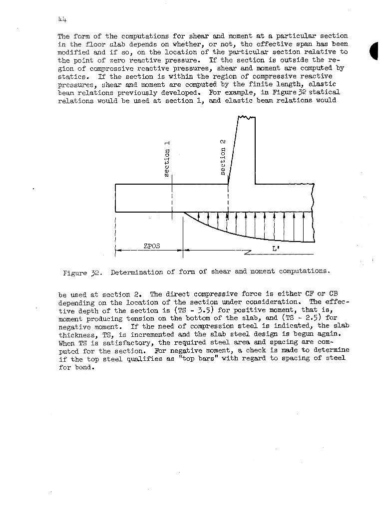
The form of the computations for shear and moment at a particular section in the floor slab depends on whether, or not, the effective span has been modified and if so, on the location of the particular section relative to the point of zero reactive pressure. If the section is outside the re- gion of compressive reactive pressures, shear and moment are computed by statics. If the section is within the region of compressive reactive pressures, shear and moment are computed by the finite length, elastic beam relations previously developed. For example, in Figure32 statical relations would be used at section 1, and elastic beam relations would
ZPOS * * t
e / L'
Figure 32. Determination of form of shear and moment computations.
be used at section 2. The direct compressive force is either CF or CB depending on the location of the section under consideration. The effec- tive depth of the section is (TS - 3.5) for positive moment, that is, moment producing tension on the bottom of the slab, and (TS - 2.5) for negative moment. If the need of compression steel is indicated, the slab thickness, TS, is incremented and the slab steel design is begun again. When TS is satisfactory, the required steel area and spacing are com- puted for the section. For negative moment, a check is made to determine if the top steel qualifies as "top bars" with regard to spacing of steel for bond.

45
T3F Type Steel areas and spacings are determined for the thirty points defined in Figure 33. A cut-off or key wall is designed at the end of the toe when necessary to ensure adequate stability against sliding of the re- taining wall portion of the channel. The design of stem wall steel is the same as type TlF channels. 1
f7 '51 231 I ,
1 I t-----L E/2 FTG/2
Figure 33. Type T3F steel layout and point locations.
Sliding stability of base. I#2 produces critical conditions for slid- ing of the retaining wall portions of the channel. Often the base de- velops adequate sliding resistance without using a key wall. This check is made first. A factor of safety against sliding of 1.5 is required. The backfill is assumed capable of developing passive lateral pressures, The lateral pressure ratio is KPASS. The coefficient of friction between concrete and soil is CFSC. A waterstop between the pavement slab and the base is assumed effective at the elevation of the bottom of the base slab, thus the horizontal force due to the water in the channel, in lbs per ft, is
HIN = 0.5 x 62.4 x (EC + TS/l2>=
For the case shown by Figure 34, the maximum external lateral forces, in lbs per ft, are
I-n =0.5x GMOISTX KeMSx (HDll?F)2
H2 = GMOIST x KPASS x HDIFF x (HW2 + TS/12)

46
H3 = 0.5 x GHJOY x KPASS x (HW2 + TS/12)2
H4 = 0.5 x 62.4 x (HW2 + TS/12>2
A I I HDIFF
1 X ///I/// 1
4 4 t - HB
- -
I + - Hw2
VN-ET x CFSC
LY!slrrq --- _-__--__- _____ --_-- 1
TKEY (VNET + VE) x CFSS
Figure 34. Sliding of type T3F retaining wall portion.
The algebraic sum of the vertical forces acting on the base portion, in lbs per ft,'is
VNET = 62.4 x KC x x + 6.25 x EC x (TT + TB) + PFTG x FTG + 12.5 x TS x w - 62.4 x (hW2 + TS/12) x w
The sum of the resisting horizontal forces, in lbs per ft, is
HR=H~+H~+H~+H~+VNEX'XCFSC If
HR/Hm 2 1.5
the base does not require a key wall. If
HR / HIN < 1.5
a key wall is required. The depth of the key wsJl is set initially at 1.0 f't; it will be incremented as necessary to obtain an adequate sliding safety factor. The key wall causes an additional lateral force, in lbs per ft, of
HKEX =(KFASS x CMOIST x HDIFI? + KPASS x GBUOY x (HW2 + TS/12 + 0.5 x !ZKEY)) x !ZXEY
47
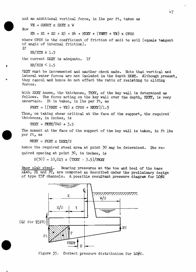
and an additional vertical force, in lbs per f-t, taken as
VE =GEKJOYx ZKEXxW Now
where CFSS is the coefficient of friction of soil to soil (equals tangent of angle of internal friction). If
the current ZKEX is adequate. If
HR/HIN < 1.5
ZKEY must be incremented and lateral water forces are not they cancel and hence do not forces.
another check made. Note that vertical and included in the depth ZKEX. Although present, effect the ratio of resisting to sliding
With ZKEY known, the thickness, TKEX, of the key wall is determined as follows. The force acting on the key wall over the depth, ZKEX, is very uncertain. It is taken, in lbs per ft, as
FKEX = (&NET + VE) x CFSS + HKXY)/1.5
Thus, on taking shear critical at the face of the support, the required' thickness, in inches, is
TKEX = m/840 + 3.5
The moment at the face of the support of the key wall is taken, in ft lbs per ft, as
KEY=FKEyxzxEY/2
hence the required steel area at point 30 may be determined. The re- quired spacing at point 30, in inches, is
s(so> = 10,015 x @KEY - 3.5yFImY
Base slab steel. Bearing pressures at the toe and heel of the base slab, Pl and P2, are computed as described under the preliminary design of type T3F channels. A possible resultant pressure diagram for LC#2
Figure 35. Contact pressure distribution for LC#Z.

48
is shown in Figure 35. Shear, moment, and direct force are computed at the various selected sections. For example at X/2 in the toe for LC#2
P = (VNET/W)(l + 12 x E x Y/(W x W))
then the components of shear, in lbs per ft, are
vl = 0.5 x PI. x (x/2)
v2 = 0.5 x P x (x/.2)
~3 = (-62.4 x HT - 12.5 x TS -I- 62.4 x (HW2 + TS/12)) x (X/2)
so the total shear on the section is
vs =vl +v2 +v3. The moment on the section, in ft lbs per ft, is
MS = V-l x (2/3) x (X/2) + v2 x (l/3> x (x/2) + v3 x (x/2)
Components of the direct force, in lbs per ft, are
HL= 0.5 x GMOIST x K02 x (HOIFF)2
H2 = @JOIST x K02 x HDIFF x (HW2 + TS/12)
II3 = 0.5 x GBUOY x K02 x (HW2 + TS/12)2
1x4 = 0.5 x 62.4 x (HW2 + TS/12)2
H5 = 0.5 x 62.4 x (HTj2 If a key w&l is used, the direct force on the section for LC#2 is taken as
When the load condition is IC#l or if there is no key wall, the frictional force is assumed uniformly distributed along the base. Hence the direct force, with no key wall, is
NS = (X/2)(KL + H2 + I-33 + H4 - H5>/W
.If the moment, MS, is positive the steel area and spacing pertain to the steel at the bottom of the slab at this section. If MS is negative, the steel area and spacing pertain to the steel at the top. The base thick- ness, TS, is incremented if necessary and the detail design of the retain- ing wall portion of the channel is begun again.
Pavement slab steel. 'Pavement slab steel is governed by requirements for temperature and shrinkage or by direct compressive force. For U#l the direct compressive force in the pavement slab is taken as the maximum direct compressive force in the toe of the retaining wsll base. It is assumed transferred to the pavement slab by bearing. For LC#2, the direct compressive force has two components. One is due to the water in the channel which causes pressure on the ends of the pavement slab. This force, in lbs per ft, is taken conservatively as
NSHT = 62.4 x (ID + TP/24)(TP/12)
The other component is zero if the direct force in the retaining wall base toe is tension, otherwise the component is taken as the maximum direct compression force in the toe of the base.
49
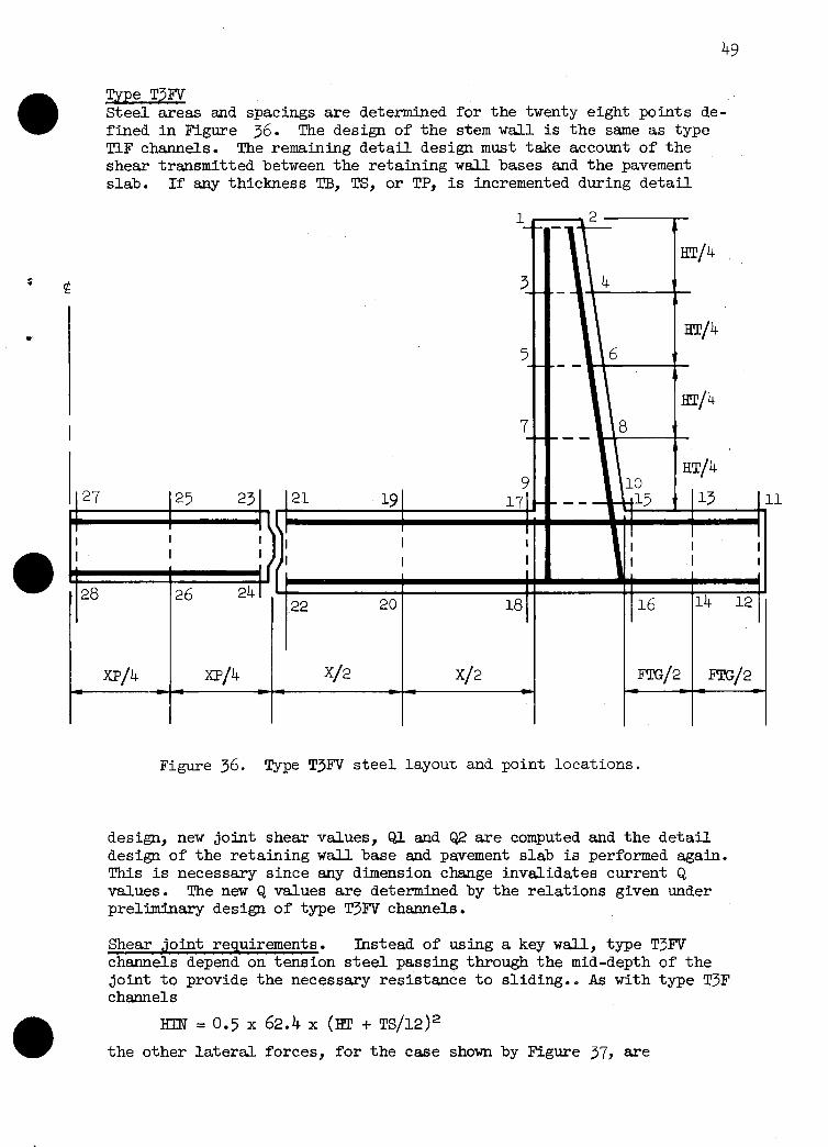
Type T3FV Steel areas and spacings are determined for the twenty eight points de- fined in Figure 36. The design of the stem wall is the same as type TlF channels. The remaining detail design must take account of the shear transmitted between the retaining wall bases and the pavement slab. If any thickness LIB, TS, or TP, is incremented during detail
28
HT/4
Figure 36. Type T3FV steel layout and point locations.
design, new joint shear values, Q,l and Q2 are computed and the detail design of the retaining wall base and pavement slab is performed again. This is necessary since any dimension change invalidates current Q values. The new Q values are determined by the relations given under preliminary design of type T3FV channels.
Shear joint requirements. Instead of using a key w&l, type T3FV channels depend on tension steel passing through the mid-depth of the joint to provide the necessary resistance to sliding.. As with type T3F channels
m = 0.5 x 62.4 x (In + TS/l2>2
the other lateral forces, for the case shown by Figure 37, are

50
HI = 0.5 x GMOIST x K02 x (HDE?'F)2
H2 = GMOIST x K02 x HDIFF x (HW2 + TS/12)
H3 = 0.5 x GBUOY x K02 x (HW2 + TS/12)2
H4 = 0.5 x 62.4 x (HW2 -I- TS/12>2
Figure 37. Direct tension through shear joint for LO&.
Hence the required tensile steel through the joint, in sq in per ft, is
ATENS=(Hm- (H1 + H3 + H3 + H4))/20,000.
The joint must be capable of resisting the larger absolute value of Ql and Q,2. This may be provided by a concrete shear key or a combination of shear key plus steel shear area.
Base slab steel. The detail design of the steel in the base of the re- taining wall portion is very similar to type T3F except that joint shear, C$l or Q2, is present at the end of the toe. Upward joint shear on the toe is positive. The expressions for various quantities must properly include the effect of joint shear for the load condition under investiga- tion. For instance, paralleling the discussion for type T3F, the shear and moment at X/2 in the toe for LC#2 become
vs = vl. + v2 + v3 -I- Q2 and
x9 = (2/3 x v1 +1/3 x v-2 + v3 + &(x/2). The expression for direct force on the section depends on whether the joint between the base slab and pavement slab requires tensile steel through it or not. If tension steel is not required, a frictional force is assumed uniformly distributed along the base. If tension steel is required, no frictional force along the b.ase is assumed. Hence NS is either
NS = (X/2)(Hl + H2 + H3 + H4 - H5)/W or
NS = Hl + H2 + H3 + H4 - H5
If the shear joint requires tension steel, then the required steel area for points (2l) and (22), in sq in per ft, is taken as
A(21) = A(22) = -0.5 x NS/20,000
The steel spacing at points (2l) and (22), is governed by the signs and absolute magnitudes of C&l and Q2. Positive Q determines spacing at point (22) whereas negative Q determines spacing at point (21).

51
l
t t
Pavement slab steel. The pavement slab of type T3FV channels is sub- ject to bending moment and to shear due to the transfer of joint shears. The Pavement slab is assumed to act as a uniformly loaded, simple span between joints. The udform loading is 2 x IQl/(XP). Thus at XP/4 for LC#l, the shear is
vs = IQll - (2 x IQII/(XP))(XP/4)
the moment is
MS = lqLl x (XP/4) - 2 x ~QJ~/(XP>(@+>~/~
and the direct force is taken as the maximum direct compressive force in the toe of the retaining waU base.
Positive Q controls steel on the top of the slab while negative Q con- trols bottom steel.
For U#2 the direct force in the pavement slab has two components as described for type T3F channels. The second component is either - ATENS x 20,000 if ATENS > 0, or the maximum direct compressive force in the toe of the base if ATENS = 0.
Figure 38. Pavement design for LC#l, Ql > 0.

53
Type T!lS Steel areas and spacings are determined for the twenty two points, on the wall and floor slab, defined in Figure 39. Steel areas and re- quired perimeters are also determined for the eight points, on the edge beam, defined in Figure 40. Tension and/or compression steel required
r 1 I
I.
m
I I I ; I I I
I
2 i-7 4 -- - c HC/4
-- t -
HC/4
-- ! \6 . t Y A A -
HC/4
8 8 ---, ---, -
HC/4
\’ I I I 122 20 181 116 14
B/4 B/4 MIGI2 m/2 - c Figure 39. Type TlS steel layout and point locations.
in the struts is determined during preliminary design.
Wall and floor slab steel requirements sre determined at five cross sections along the longitudinal span between transverse channel joints. These five sections are (1) the sections immediately adjacent to the transverse channel joints, (2) th e sections at the struts, and (3) the section mid way between the struts. Rather than list all five (three because of symmetry) sets of steel requirements, one composite set is reported. This set consists of the maximum required area and minimum allowable spacing corresponding to each of the twenty two points in the composite section.
Whenever, in the process of detail design, it is necessary to increment either TB, TS, or ET, new edge beam loads are computed, new struts are designed, and the detail design is begun again. This is necessary since any dimension change alters existing spans, loads, and relative stiff- nesses, all of which affect edge beam loading.

6t--
; I r----7----- I
7 15
Figure 40. Plan of edge beam, steel layout and point location.
Wall steel. Design of wall steel at any one of the cross sections listed above is essentially the same as the design of type TlF walls except that the support provided the wall by the-edge be-am, at the particular cross section being investigated, is included in the compu- tations for shear and moment. The direct compression force includes the weights of the struts and edge beam as well as the w&l.
As previously noted, the sense of the edge beam loading may be either positive or negative for either IC#l or LC#2. Thus the sense of the moment at any distance, Z, below the top of the wall is unpredictable. Moment expressions are therefore written such that positive moment in- dicates steel required at an even numbered point in the wall while negative moment indicates steel at an odd numbered point. Thus if both LC#l and LC#2 produced negative moments at a particular Z Clue, the largest area and smallest spacing would be tabulated for the corresponding odd numbered point.
Floor slab steel. The design of floor slab steel at any cross-section is essentially the same as the design of type TlF floor slabs. It is only necessary to modify the expressions for MW, NW, and HWAU, see page 42,. to include the effects of edge beam loadings and weights. Assume a positive edge beam loading, RXL, in lbs per ft, is added to Figure 31. Then the term -RXL x (HT - ED/24 + TS/24) is added to the expression for MW and the term -RXl is added to the expression for HWALL. The value of Rx1 is that at the particular cross section under investigation. The term 15O(E!T - TT) x m/144 plus a term accounting for strut weight is added to the expression for NW. With these changes, the analysis proceeds as described for type TlF channel floor slabs.
Edge beam steel. A summation process is used to obtain the shears and moments at the one-eighth points of the edge beam span, Either load condition can produce moments of either sense at any section of the span. Hence an approach similar to that indicated for the wall steel is used here to determine critical steel requirements at the odd and even number- ed points shown in Figure 40.
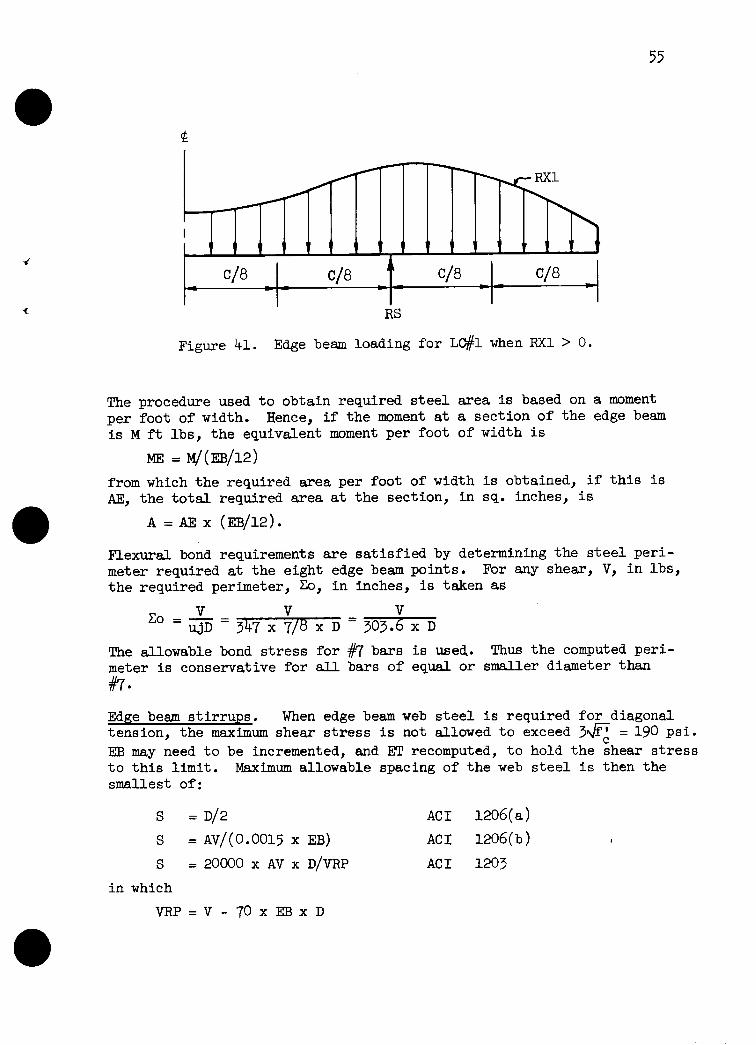
55
RS
Figure 41. Edge beam loading for LC#l when RX1 > 0.
The procedure used to obtain required steel area is based on a moment per foot of width. Hence, if the moment at a section of the edge beam is M ft lbs, the equivslent moment per foot of width is
ME = &&B/12)
from which the required area per foot of width is obtained, if this is AE, the total required area at the section, in sq. inches, is
A = AF x @B/12).,
Flexural bond requirements are satisfied by determining the steel peri- meter required at the eight edge beam points. For any shear, V, in lbs, the required perimeter, Co, in inches, is taken as
V co=-= u.P 347 x ;,8 x D = 303.: x D
The allowable bond stress for #7 bars is used. Thus the computed peri- meter is conservative for all bars of equal or smaller diameter than iw
Edge beam stirrups. When edge beam web steel is required for diagonal tension, the maximum shear stress is not allowed to exceed 3yif? = 190 psi. ED may need to be incremented, and ET recomputed, to hold the shear stress to this limit. Maximum allowable spacing of the web steel is then the smallest of:
S = D/2 AC1 1206(a)
S = AV/(O.0015 x EB)
S = 20000 x AV x D/VRP
in which
VRP=V -70xEtBxD
AC1 1206(b)
AC1 1203

56
where v = shear at section under investigation, in lbs per ft
VPR = shear carried by web steel, in lbs per ft
D = effective depth, in inches
AV = area of web steel, twice the bar area, in sq inches
S = maximum allowable web steel spacing, in inches
AV is initially set at 0.22 sq in for #3 stirrups. If S, for this area, is less than 4 inches, the stirrup size is increased to #4, the spacing is recomputed, etc. Although the maximum allowable spacing may be com- puted at either sections D distance from the faces of the supports or the section at the centerline of the support, the spacing is conserva- tively reported as that at D from the faces.
The web steel layout may be selected by consideration of a diagram similar to that of Figure 42. quired values of AVIS.
The ordinates of the diagram are re- They may be assumed to vary linearly from zero
to a maximum over the supports. The ordinate at D from the faces of the strut is obtained from the required stirrup size and spacing com- puted above.
Nominal #m2
r 3
vary size and spacing as desired
I l
L
AV/S for computed size and spacing
c/4
computed size and
spacing < B
A 0 . .\
vary size and spacing as desired
( 1
Nominal #m2
( b
LAV/S for nominal #3@l2 = 2(.0.11)/12 = 0.0183
c/4 I‘
Figure 42. Layout of edge beam stirrups.

Computer Designs 57
Input From one to four lines of input data are required for each design run. A given computer job may include many design runs. A design run is made for a particular set of design conditions and takes one of two forms. The first form consists of four preliminary designs, one for each channel type, plus an indication of the channel type that might be selected for detail design on the basis of least concrete volume. The second form consists of the detail design of one of the four chan- nel types.
The input data provided per design run consists essentially of values for the primary design parameters and, if desired, values for the second- ary design parameters. Table 2 shows the lines that may be provided per run together with the specific parameters contained on the four lines.
Table 2. Input values per design run
B EC HB DESIGN DEFAULT 1 DEFAULT 2 DEFAULT 3 HWl Hw2 HWP GMOIST GSAT KOl K02 FLOATR MAXFIG JOINTS MFOUND ' CFSC CFSS KPASS
The first line contains the primary parameters B, HT, and HI3 and is always required. If DESIGN = 0, the four preliminary designs are per- formed. If DESIGN = 1, 2, 3, or 4, then the detail design of type TlF, T3F, T3FV, or TlS is performed. (If d esired, the Design Unit can run the detail design of the structural channel type indicated from the pre- liminary designs. However, it will often be a better procedure if the concerned designer will take a critical look at the preliminary design results before a detail design is run.)
If DEFAULT 1 > 0, the next line of input data must be provided, it con- tains values for HWl through FLOATR as indicated. If DEFAULT1 =O, this line of input data must not be included, default values for the eight parameters will be provided by the computer.
If DEFAULT 2 > 0, the next line containing values for MAXFTG, JOINTS, and MFOUND must be provided. If DEFAULT 2 = 0, default values will be used and the line must be omitted, similarly for DEFAULT 3 and the line containing CFSC, CFSS, and KPASS.
Thus the number of lines of data that must be provided per design run will vary depending on whether the default values are satisfactory or whether the user wishes to supply some or all of the secondary parameter values. Note that although various lines may be omitted, those supplied must be complete and in the order indicated.
output The output for each design run, whether preliminary designs or a detail design, gives the parameter values assumed for that run. These para- meters are listed and identified at the beginning of the design.
Revised 'i'/'i'7

58
Preliminary designs. Preliminary design results sre listed in the order TlF, T3F, T3FV, and TlS, see Figure 43. Output values consist of distances, thicknesses, and concrete volumes in cubic yards per longitudinal foot of channel. The thicknesses and distances, in inches and feet, may be identified by reference to various figures:
for type TlF see Figures 5 and 6 for type T3F see Figures 5, 7, and 9 for type T3FV see Figures 5, 7, and 9
_ for type TlS see Figure 13.
Detail Designs. The output for the detail design of any channel type includes three segments: a repeat of the preliminary design results, a similar output giving final dimensions (this will often be identical to the preliminary design values), and a listing of steel requirements giving required area and maximum allowable spacing in sq. in. per ft and inches.
!I&pe TlF. - See Figures 44 and 45 for output the steel locations listed.
Type T3F. - See Figures 46 and 47 for output for the steel locations listed. Note that a Figure 47, the required depth of the wall is quired thickness of the wall is given in inches.
examples, see Figure 29 for
examples, see Figure 33 key wall is required in given in ft and the re-
Type T3FV. - See Figures 48 and 49 for output examples, see Figure 36 for the steel locations listed. Note that the shear forces transmitted across the shear joint are given in lbs per ft for LC#l and LC#2. The tension steel area, in sq inches per ft, through the joint is also given.
Type TlS. - See Figures 50 and 51 for output examples, see Figures 39 and 40 for wall and edge beam steel locations. Required strut steel areas, in sq inches, are given for tension and compression. Required edge beam web steel is given by bar size and spacing in inches. Required edge beam longitudinal steel areas, in sq inches, and perimeters, in inches, are given for eight locations.

59 *********************************** ********************************************
RECTANGULAR STRUCTURAL CHANNEL CROSS SECTION DESIGN
ELASTIC ANALYSIS AND WORKING STRESS DESIGN ARE USE0
SPECIAL DESIGN PREPARED BY THE DESIGN UNIT Al HYATTSVILLEs ND. FOR
EXAMPLE SPECIAL OESIGNS FOR STRUC7URAL CHANNEL TECHNICAL RELEASE JOAN FOR ESA ---------- ?/?T
DESIGN PARAMETERS R* 24.00 nrl1= 12.00 KOl= 0.80
HT* 16.00 HW2’ 1.50 KO2= 0.20 HR. 15.00 HYP= 12.00 KPASS= 1.25
CFSC= 0.35
PRELIMINARY DESIGNS FOLLOW
TYPE TlF STRUCTURAL CHANNEL - TT= 10.00 TR= 19.00 TS= 24.00
TYPE T3F STRUCTURAL CHANNEL - XI 10.00 TP= 90.00 XPE 4.00
TTr 10.00 TG= 19.00 TS= 20.00
FLOATR= 1.50 JOINTS* 40.00 MAXFTG= 12.00
CFSS= 0.55
TRIAL VALUES FTG PROJ=10.60
TRIAL VALUES
FTG PROJ= 9.00
TYPE T3FV STRUCTURAL CHANNEL - TRIAL VALUES x- 3.00 TP= 32.00 XPI 18.00
TT* 10.00 TB= 19.00 TS= 20.00 FTG PROJ=11.60
TYPE TlS STRUCTURAL CHANNEL - TRIAL VALUES SR. 12.00 ST= 15.00 EG= 15.00 ET* 26.00 TT* 10.00 TR= 21.00 TS= 22.00 FTC PROJ=lO.*O
MFOUND= 100000. GMOIST= 120.
GSAT= 140.
QUINT= 5.015
QUANT= 5.084
QUANT= 5.208
QUANT* 4.990
.*..***.......***..*.**.**.*.***.***.**.
TYPE T1S STRUCTURAL CHANNEL MIGHT GE SELECTED FOR DETAIL DESIGN, QUINT= 4.990
*************************** END PRELININARV DESIGNS ***************************
*********************- -*********************************************************
RECTANGULAR STRUCTURAL CHANNEL CROSS SECTION DESIGN
ELASTIC ANALYSIS AN0 WORKING STRESS DESIGN ARE USED
SPECIAL DESIGN PREPARED BY THE DESIGN UNIT AT HYATTSVILLE, MD. FOR
EXAMPLE SPECIAL DESIGNS FOR STRUCTURAL CHANNEL TECHNICAL RELEASE JOAN FOR ESA ---------- T/17
DESIGN PARAMETERS 8. 24.00 nw1: 0.0 KOl= 0.80
HT* 16.00 WY.?’ 0.0 KO2r 0.20 He* 15.00 HrlP= 0.0 KPASS= 1.25
CFSC= 0.35
PRELIMINARY DESIGNS FOLLOW
TYPE TlF STRUCTURAL CHANNEL - TT: 10.00 TR= 18.00 TS= 19.00
TYPE T3F STRUCTURAL CHANNEL - X= 12.00 TP= 11.00 xp= 0.0
TT* 10.00 TR= le..00 TS* 19.00
FLOATR* 1.50 JOINTS= 40.00 WAXFTG* 12.00
CFSS= 0.55
TRIAL VALUES FTC PROJ* 0.0
TRIAL VALUES
FTC PROJ= 2.80
TYPE T3FV STRUCTURAL CHANNEL - TRIAL VALUES x* 6.00 TP= 11.00 XP= 12.00
IT* 10.00 Ttl= 18.00 TS= 19.00 FTG PROJ= 4.40
TYPE TlS STRUCTURAL CHANNEL - TRIAL VALUES SR. 12.00 ST= 15.00 ER= 15.00 ET= 23.00 TT* 10.00 TR= 12.00 TS= 13.00 FTG PROJ= 0.0
MFOUND= 100000. GMOIST= 120.
GSAl= 140.
QUINT= 2.966
QUANT* 3.294
QUANT* 3.186
QUANT* 2.285
*****~*...*.**.*..*****.****..*.***...*.
TYPE TlS STRUCTURAL CHANNEL MIGHT GE SELECTED FOR DETAIL DESIGN* QUANT= 2.285
********* ****************** END PRELIMINARY DESIGNS ***************************
Figure 43. Computer output, preliminary designs.
Revised 7/77

60
RECTANGULAR STRUCTURAL CHANNEL CROSS SECTION DESIGN
ELASTIC ANALYSIS AND WORKING STRESS DESIGN ARE USED
SPECIAL DESIGN PREPARED BY THE DESIGN UNIT AT HYATTSVILLE, MD. FOR
EXAMPLE SPECIAL DESIGNS FOR STRUCTURAL CHANNEL TECHNICAL RELEASE JOAN FOR ESA -m------m 2/2CJ/72
DES I GN PARAMETERS B= 24.00 HWl= 0.0 KOl= 0.80 F LOATR= 1.50
HT= 16.00 HW2= 0.0 K02= 0.20 JOINTS= 40.00 HB- 15.00 HWP- 0.0 KPASS= 1.25 MAXFTG= 12.00
CFSC= 0.35 CFSSp 0.55
DESIGN OF SPECIFIED TYPE FOLLOWS
TYPE TlF STRUCTURAL CHANNEL - TRIAL VALUES TT= 10.00 TB= 18.00 TS= 19.00 FTG PROJ= 0.0
TYPE TlF STRUCTURAL CHANNEL - DETAIL DESIGN TT= 10.00 TB= 18.00 TS= 20.00 FTCi PROJ= 0.0
STEEL REQUIREMENTS WALL
A( l)= 0.24 SC l)= 18.00 A( 2)= 0.24 St 215 18.00 A( 3)= 0.29 SC 3)= 18.00 A( 4)= 0.14 SC 4)~ 18.00 A( 5)= 0.34 St 5)= 18.00 A( 6)= 0.27 SC 6)~ 18.00 A( 7)= 0.55 St 71~ 18.00 A( 8)= 0.99 St 8)~ 18.00 A( 9)= 1.17 S( 9)= 18.00 AtlO)= 2.31 S(lO)= 14.37
BASE A(111 - A(161 DO NOT EXIST SINCE FTG=O
A(1713 1.45 .S(17)= 18.00 A(18)= 2.16 S(18)= 18.00 A(19)= 1.47 S(19)= 18.00 A(20)= 1.33 S(20)= 18.00 A(21)= 1.34 .5(21)= 18.00 A(22)= 0.90 S(22)= 18.00
MFOUND- 100000. GMOlST= 120.
GSAT- 140.
QUAkIT= 2.966
QUANT- 3.049
Figure 44. Computer output, type TlF detail design.

61
- - - - _ - - - ,,,,_,_,==‘=====S===I=L===‘==P=0===PP=I==========-- ---a---- --=========o==========--------
RECTANGULAR STRUCTURAL CHANNEL CROSS SECTION DESIGN
ELASTIC ANALYSIS AND WORKING STRESS DESIGN ARE USED
SPECIAL DESIGN PREPARED BY THE DESIGN UNIT AT HYATTSVILLEv MD. FOR
EXAMPLE SPECIAL DESIGNS FOR STRUCTURAL CHANNEL TECHNICAL RELEASE JOAN FOR ESA ---------- 7177
DESIGN PARAMETERS R= 24.00 rlldl= 12.00 KOl= 0.80 FLOATR= 1.50
WT= 16.00 HW2= 1.50 K02= 0.20 JOINTS= 40.00 HB= 15.00 HWP= 12.00 KPASS= 1.25 MAXFTG’ 12.00
CFSC= 0.35 CFSS= 0.55
DESIGN OF SPECIFIED TYPE FOLLOWS
TYPE TlF STRUCTURAL CHANNEL - TRIAL VALUES TT= 10.00 TB= 19.00 TS= 24.00 FTG PROJ=10.60
TYPE TlF STRUCTURAL CHANNEL - DETAIL DESIGN TT= 10.00 TR= 19.00 TS= 24.00 FTG PROJ=10.60
STEEL REQUIREMENTS WALL
A( l)= 0.24 S( lb= 18.00 A( 2)= 0.24 S( 2)= 18.00 A( 3)= 0.29 St 3)= 18.00 A( 4)= 0.15 S( 4)= 18.00 A( 5)= 0.35 St 5)= 18.00 A( 6)= 0.27 St 6)= 18.00 A( 7)= 0.52 St 7)= 18.00 A( 8)= 1.05 St 8)= 18.00 A( 9)= 1.08 St 9)= 18.00 A(lO)= 2.50 S(lO)= 12.86
BASE A(ll)= 0.29 s(ll)= 18.00 A(12)= 0.29 S(12)= 18.00 9(13)= 0.29 st131= 18.00 A(14)= 0.29 st141= 18.00 A(lS)= 0.84 st151= 18.00 A(1611 0.40 S(16)= 18.00
A(17)= 0.72 st17j= 18.00 AtlEo= 0.39 s(lB)= 18.00 A(19)= 0.82 s(19)= 18.00 At20)= 0.29 st201= 18.00 A(21)= 0.80 s(21)= 18.00 A(22)= 0.29 s(22)= 18.00
WFOUND= 100000. GHOIST= 120.
GSAT= 140.
QUANT= 5.015
QUANT= 5.015
=========‘========t=r============ END TlF DESIGN ==o=========II=P===P===========
Figure 45. Computer output, type TlF detail design.
Revised 7177

62
I==IIPE==============PEI============~==------~=========~~==~=---=-=====-===-====~ ------
RECTANGULAR STRUCTURAL CHANNEL CROSS SECTION DESIGN
ELASTIC ANALYSIS AND WORK1 NG STRESS DESIGN ARE USED
SPECIAL DESIGN PREPARED BY THE DES I GN UNIT AT HYATTSVI LLE, MD. FOR
EXAMPLE SPECIAL DESIGNS FOR STRUCTURAL CHANNEL TECHNICAL RELEASE JOAN FOR ESA --------- z/29/72
DES I GN PARAMETERS B= 24.00 HWl= 0.0 KOl= 0.80 F LOATR= 1.50
HT= 16.00 HW2 = 0. 0 KO2= 0.20 JOINTS= 40.00 HB= 4.00 HWP= 0.0 KPASS- 1.25 MAXFTG= 12.00
CFSC= 0.35 CFSS= 0.55
DESIGN OF SPECIFIED TYPE FOLLOWS
TYPE T3F STRUCTURAL CHANNEL - TRIAL VALUES x= 10.00 TP= 11.00 XP= 4.00
TT= 10.00 TB= 16.00 TS= 17.00 FTG PROJ= 4.60
TYPE T3F STRUCTURAL CHANNEL - DETAIL DESIGN x= 10.00 TP= 11.00 XPP 4.00
TT= 10.00 TB= 16.00 TS= 17.00 FTG PROJ= 4.60
STEEL REQUIREMENTS WALL
MFOUND= 100000. GM0 I ST= 120.
GSAT= 140.
QUANT= 3.092
QUANT- 3.265
Iii 21;: ;.;f:
A( 3)= 0:28 31 31: :;*;; St 3)= 18:OO
A( 4)~ 0.28 SC 4)~ 18.00 A( 5)= 0.31 St 5)= 18.00 A( G)= 0.31 St 6)~ 18.00 A( 7)= 0.94 SC 7)~ 18.00 A( 8)~ 0.35 St 8)= 18.00 A( 9)= 2.08 SC 9)s 17.34 AtlO)= 0.19 S(lO)= 18.00
BASE A(ll)= 0.20 A(12)= 0.20 A(13)= 0.20 A(14)= 0.20 A(lS)= 0.20 A(16)= 0.65
S(ll)= 18.00 S(12)= 18.00 S(13)= 18.00 S(14)= 18.00 S(lS)= 18.00 S(lG)= 18.00
A(17)= 1.75 St1713 18.00 A(1811 0.20 S(18)= 18.00 A(19)= 0.70 S(19)= 18.00 A(20)= 0.20 S(20)= 18.00 A(21)= 0.41 S(21)= 18.00 A(22)= 0.20 S(22)= 18.00
KEY WALL DEPTH= THICK= A(29)= A(30)=
PAVEMENT SLAB A(23)= A(24)= A(25)= A(2G)= A(27)= A(28)=
2.00 14.00
0.17 0.50
0.26 0.13 0.26 0.13 0.26 0.13
S(29)= 18.00 S(30)= 12.87
S(23)= 18.00 S(24)= 18.00 S(25)= 18.00 S(26)= 18.00 S(27)= 18.00 S(28)= 18.00
P=PI=~===P-------I=P===IPIII=II END J-SF DESIGN I=IIPPIPEPIPP~=PPPP--=-=======- -___---
Figure 46, Computer output, type 'T3F detail design.
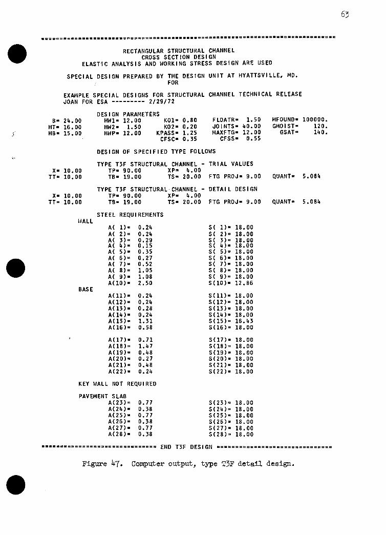
ooPOooPP.PoPooPoPoOoooo~ooooooooooo*==o=- -0000000000000000000.0.0.0.000000000000
RECTANGULAR STRUCTURAL CHANNEL CROSS SECT ION DES I GN
ELASTIC ANALYSIS AND WORKING STRESS DESIGN ARE USED
SPECIAL DESIGN PREPARED BY THE DESIGN UNIT AT HYATTSVILLE, MD. FOR
EXAMPLE SPECIAL DESIGNS FOR STRUCTURAL CHANNEL TECHNICAL RELEASE JOAN FOR ESA --------- 2/2g/72
DES I GN PARAMETERS B- 24.00 HWl= 12.00 KOl- 0.80 F LOATR- 1.50 MFOUND- 100000.
HT- 16.00 HW2= 1.50 K02= 0.20 JOINTS= 40.00 GMOI ST- 120. HB= 15.00 HWP- 12.00 KPASS- 1.25 MAXFTG- 12.00 GSAT- 140.
CFSC- 0.35 CFSS- 0.55
DESIGN OF SPECIFIED TYPE FOLLOWS
TYPE T3F STRUCTURAL CHANNEL - TRIAL VALUES x- 10.00 TP- 90.00 XP- 4.00
TT= 10.00 TB- 19.00 TS= 20.00 FTG PROJ= 9.00 QUANT- 5.084
TYPE T3F STRUCTURAL CHANNEL - DETAIL DESIGN x- 10.00 TP- 90.00 XP- 4.00
TT= 10.00 TB- 19.00 TS= 20.00 FTG PROJ- 9.00 QUANT- 5.084
STEEL REQU I REMENTS NALL
A( l)= 0.24 S( l)= 18.00 A( 2)= 0.24 St 2)= 18.00
;I 43,‘: ;*;; A( 5)= 0:35 A( 6)= 0.27 A( 7)= 0.52 A( 8)= 1.05 A( 9)= 1.08 AilOj- 2.50
BASE A(ll)= 0.24 A(12)= 0.24 A(13)= 0.28 A(14)= 0.24 A(lS)= 1.31 A(lS)= 0.58
A(17)= 0.71 A(1813 1.47 A(19)= 0.48 A(20)= 0.27 A(21)= 0.48 A(22)= 0.24
SC 3)= 18.00 S( 4)= 18.00 St 5)= Si 6j=
18.00 18.00
St 7)= 18.00 St 8)= 18.00 S( 9)= 18.00 S(lO)= 12.86
S(ll)= 18.00 S(12)= 18.00 S(13)= 18.00 S(14)= 18.00 S(15)= 16.43 S(16)= 18.00
S(17)= 18.00 S(18)= 18.00 S(19)= 18.00 S(20)= 18.00 S(21)= 18.00 S(22)= 18.00
KEY WALL NOT REQUIRED
PAVEMENT SLAB A(23)= 0.77 S(23)= 18.00 A(24)= 0.38 S(24)= 18.00 A(25)= 0.77 S(25)= 18.00 A(26)= 0.38 S(26)= 18.00 A(27)= 0.77 S(27)= 18.00 A(28)= 0.38 S(28)= 18.00
ooo~.~~coooooo~~~o~~ooooooooooo END T3F DESIGN ~~.~oooo 00000000000000000000000
Figure 47. Computer output, type T3F detail design.
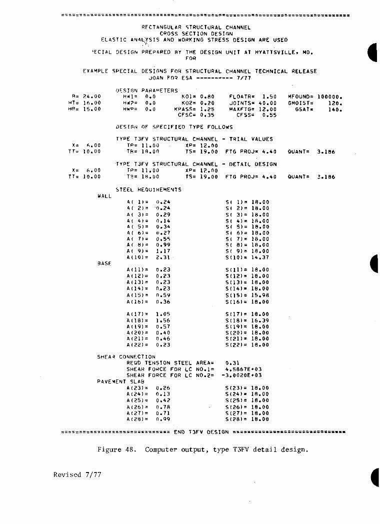
RFCTANGULAR STRUCTURAL CHANNEL CROSS SECTION DESIGN
ELASTIC ANAs,YSIS AN0 WORKING STRESS DESIGN ARE USED
‘ECIAL DESIGN PREPPREO RY THE DESIGN UNIT AT HYATTSVILLEv MD. FOR
EXAMPLE SPECIAL DESIGNS FOR STRUCTURAL CHANNEL TECHNICAL RELEASE JOAN FOR ESA ---------- 7/77
DESIGN PARAMETERS R= 24.00 l-!UJl= n.O KOl= 0.80 FLOATR= 1.50 MFOUND= 100000.
HT= 16.00 Hw?= 0.0 K02= 0.20 JOINTS= 40.00 GMOIST= 120. HR= 15.00 HWP= 0.0 KPASS= 1.25 MAXFTG= 12.00 GSAT= 140.
CFSC= 0.35 CFSS= 0.5s
OESIGN OF SPECIFIED TYPE FOLLOWS
TYPE T3FV STRUCTURAL CMANNEL - TRIAL VALUES
x= 6.00 TP= 11.00 XP= 12.00 TT= 10.00 TR= 18.00 TS= 19.00 FTG PROJ= 4.40 QUANT= 3.186
TYPE T3FV STRUCTURAL CHANNEL - DETAIL DESIGN x= 6.00 TP= 11.00 XPZ 12.00
TT= 10.00 TEJ= 18.00 TS= 19.00 FTG PRDJ= 4.40 QUANT= 3.186
STEEL HEQUIWEYEYTS WALL
4( l)= 0.24 A( El= 0.24 A( 31= 0.29 A( 4)= 0.14 A( 5)= 0.34 A( 6)= 0.27 A( 7)= 0.55 A( RI= 0.99 A( 9)= 1.17 A(lOl= 2.31
BASE A(ll)= 0.23 A(lP)= 0.23 A(13)= 0.23 4(14)= 0.23 A(lS)= 0.5Y A(16)= 0.36
S( l)= 18.00 S( 2)= 18.00 S( 3)= 18.00 S( 4)= 18.00 S( S)= 18.00 St 6)= 18.00 S( 7)= 18.00 S( a)= lA.00 S( 9)= 18.00 S(lO)= 14.37
s(ll)= 18.00 S(l2)= 18.00 S(13)= 18.00 S(14)= 18.00 S(15)= 15.98 S(16)= 18.00
A(17)= 1.05 S(17)= 18.00 A(ld)= 1.56 S(lB)= 16.39 A(19)= 0.57 st191= 18.00 A(20)= 0.40 S(EO)= 18.00 A(21)= 0.46 S(21)= 18.00 A(22)= 0.23 S(22)= 18.00
SHEAR CONNECTION REOD TENSION STEEL AREA= 0.31 SHEAR FORCE FOR LC NO.l= 4.5867E*03 SHEAR FORCE FOR LC N0.2= -3.0020E+03
PAVEMENT SLAB A(23)= 0.26 S(23)= 18.00 A(24)= n.13 S(24)= 18.00 A(25)= 0.42 S(25) = 18.00
A(26)= 0.7A S(26)= 18.00 A(27)= 0.71 S(27)= 18.00 A(2H)= 0.99 st28)= 18.00
Figure 48. Computer output, type TSFV detail design.
Revised 7/77

It======--------------------------- ---------------------------============================================
RECTANGULAR STRUCTURAL CHANNEL CROSS SECTION DESIGN
ELASTIC ANALYSIS AN0 WORKING STRESS DESIGN ARE USED
SPECIAL DESIGN PREPARED BY THE DESIGN UNIT AT HYATTSVI FOR
EXAMPLE SPECIAL DESIGNS FOR STRUCTURAL CHANNEL TECilNICAL Rt. .ZiE JOAN FOR ESA ---------- 7/77
DESIGN PARAYETERS B= 24.00 liw1= 12.00 KOl= 0.80 FLOATR= 1.50
tiT= 16.00 tiw2= 1.50 K02= 0.20 JOINTS= 40.00 HR= 15.00 HWP= 12.00 KPASS= 1.25 MAXFTG= 12.00
CFSC= 0.35 CFSS= 0.55
DESIGN OF SPECIFIED TYPE FOLLOWS
TYPE T3FV STRUCTURAL CHAkNEL - TRIAL VALUES x= 3.00 TP= 32.00 XP= 18.00
TT= 10.00 TR= 19.00 TS= 20.00 FTG PROJ=11.60
TYPE T3FV STRUCTURAL CHANNEL - DETAIL DESIGN x= 3.00 TP= 32.00 XP= 18.00
TT= 10.00 TR= 19.00 TS= 20.00 FTG PROJ=ll.60
STEEL REQUIREMENTS
WALL A( lb= 0.24 A( 2)= 0.24 A( 3)= 0.29 A( 4)= 0.15 A( 5)= 0.35 A( 6)= 0.27 A( 7)= 0.52 A( 8)= 1.05 A( Y)= 1.08 A(lO)= 2.50
BASE A(ll)= 0.24 A(lZ)= 0.24 A(13)= 0.32 A(14)= 0.40 A(lS)= 1.74 A(16)= 1.14
A(17)= 0.48 A(la)= 0.53
X’ = 0.48 0.24 A(El)= 0.48 4(22)= 0.24
SHEAR- COvNECTION REBD TENSION STEEL AREA= SHEAR FORCE FOR LC NO.l= SHEAR FORCE FOR LC NO.2=
PAVEMENT SLAB A(2313 0.77 A(24)= 0.38 A(25)= 0.77 A(26)= 0.38 A(27)= 0.77 A(28)= 0.3R
St l)= 18.00 St 210 18.00
S( 3)= 18.00 St 4)= 18.00 St 5)= 18.00 St 6)= 18.00 S( 7)= 18.00 St 8)= lA.00 St 9)= 18.00 S(lO)= 12.86
st111= 18.00 s(12)= 18.00 S(13)= 18.00 S(14)= 18.00 S(lS)= 14.25 S(16)= 18.00
S(17)= 18.00 S(lA)= 16.85
st191= 18.00 S(ZO)= 18.00 S(21)= 18.00 S(22)= 18.00
0.31 6.5370E*03
-1.7764E*03
S(23)= 18.00 S(24)= 18.00 st25j= 18.00 S(26)= 18.00 S(27)= 18.00 S(28)= 18.00
MFOUND= 100000.
GMOIST= 120. GSAT= 140.
QUANT= 5.208
QUANT= 5.208
Figure 49. Computer output, type TSFV detail design.
Revised 7/77

66
PIPIPlellllllP=rPI=IIIIIEIPPIZIIII=D ==PPPIPtlPIPPPIPelOP=-=----=.-..-==---.--.=
RECTANGULAR STRUCTURAL CHANNEL CROSS SECTION DESIGN
ELASTIC ANALYSIS AND WORKING STRESS DESIGN ARE USED
SPECIAL DESIGN PREPARED BY THE DESIGN UNIT AT HYATTSVILLE, MD. FOR
EXAMPLE SPECIAL DES I GNS FOR STRUCTUKAL CHANNEL TECHNI CAL RELEASE JOAN FOR ESA --------- z/29/72
DESIGN PARAMETERS B= 24.00 HWl- 0.0 KOl= 0.80 F LOATR= 1.50
HT- 16.00 H\J2= 0.0 KD2= 0.20 JOINTS= 40.00 HB= 15.00 hWP= 0.0 KPASS= 1.25 MAXFTG= 12.00
CFSC= 0.35 CFSS= 0.55
DESIGN OF SPECIFIED TYPE FOLLOWS
TYPE TlS STRUCTURAL CHANNEL - TRIAL VALUES SB= 12.00 ST= 15.00 EB- 15.00 ET= 23.00 TT= 10.00 TB= 12.00 TS= 13.00 FTG PRDJ- 0.0
TYPE TlS STRUCTUKAL CHANNEL - DETAIL DESIGN SB= 12.00 ST= 15.00 EB- 15.00 ET- 23.00 TT= 10.00 TB= 12.00 TS- 13.00 FTC; PROJ- 0.0
STEEL REQUIREMENTS LIALL
A( l)= 0.24 A( 2)= 0.12
S( 115 18.00 St 2)= 18.00
Ai 3j= 0.86 St 3)= 18.00 A( 4)= 0.67 S( 4)= 18.00 A( 5)= 1.11 St 516 18.00 A( 6)= 0.95 S( 6)= 18.00 A( 71= 0.56 St 719 18.00 A( 8)= Ai 9j=
0.84 St 8)= 18.00 0.29 St 910 18.00
A(lO)= 1.04 S(lO)= 11.46 BASE
A(111 - A(161 DO NOT EXIST SINCE FTG=O
MFOUND- 100000. GM0 I ST- 120.
GSAT- 140.
QUANT- 2.285
QUANT- 2,285
A(17)= 0.31 S(17)= 18.00 A(18)= Aii9j=
1.04 S(18)= 18.00 0.42 S(19)= 18.00
A(20)= 0.16 S(20)= 18.00 A(21)= 0.39 S(21)= 18.00 A(22)= 0.16 .S(22)= 18.00
STRUT STEEL REQD TENS ION STEEL AREA = 2.15 REQD COMPRES STEEL AREA = 2.15
EDGE BEAM STEEL STIRRUPS HEQUI RED, USE AT LEAST
NO. 3 AT 9.7 IN. CC AT D DISTANCES FROM FACES OF STRUTS
A( l)= 0.85 P( l)= 1.75 A( 2)= 1.02 P( 2)= 2.10 A( 311 3.64 P( 3)= 3.56 A( 4)= 4.41 P( 413 4.28 A( 5)= 0.72 P( 5)= 1.86 A( G)= 0.86 P( 6)= 2.23 A( 7)= 3.54 P( 7)= 0.0 A( 8)= 2.77 P( 8)= 0.0
PIII=IDPPP==III==PIP-IIIPDPllfl ErJD TlS DESIGlJ PIIIPPPPIIIJII==PP=P~~~PII=PPPI
3?igure 50. Computer output, type TlS detail design.

67
%%%%%%%%%%%%%P%%%%P%%%%%%%%%%%%%%%%%%%%%%%%%%%%% %%%P%%P%%%%%PP%%%PP%%%.%%%%%%%%
RECTANGULAR STRUCTURAL CHANNEL CROSS SECTION DESIGN
ELASTIC ANALYSIS AND WORKING STRESS DESIGN ARE USED
SPECIAL DESIGN PREPARED BY THE DESIGN FOR
EXAMPLE SPECIAL DES I GNS FOR STRUCTURAL JOAN FOR ESA --------- 2,2g,,2
B- 24.00 HT- lt.OO HB- 15.00
SB- 12.00 TT- 10.00
SB- 12.00 TT= 10.00
DES I GN PARAMETERS ClWl- 12.00 KOl- 0.80 HkIZ- 1.50 K02= 0.20 HllP- 12.00 KPASS- 1.25
CFSC- 0.35
UNIT AT HYATTSVILLE, MD.
CHANNEL TECHNICAL RELEASE
FLOATR- 1.50 MFOUND- 100000. JOItlTS= 40.00 GM0 I ST- 120. !iAXFTG= 12.00 GSAT- 140.
CFSS- 0.55
DESIGN OF SPECIFIED TYPE FOLLOWS
TYPE TlS STRUCTURAL CHANNEL - TRIAL VALUES ST- 15.00 EB- 15.00 ET= 26.00 TB- 21.00 TS,= 22.00 FTC PROJ-10.40 QUANT= 4.990
TYPE TlS STRUCTURAL CHANNEL - DETAIL DESIGN ST= 15.00 EB- 15.00 ET- 26.00 TB- 21.00 TS- 22.00 FTG PROJ-10.40 QUANT- 4.990
STEEL REQUIREMENTS IJALL
A( l)= 0.26 A( 2)= 0.17 A( 3)= 0.32 A( 4)= 0.93 A( 5)= 0.38 A( 6)= 1.25 A( 7)~ 0.44 A( 8)= 1.55 A( 9)- 0.50 A(lO)= 2.83
BASE A(ll)= 0.26 A(lZ)= 0.26 A(13)= 0.26 A(14)= 0.26 A(lS)= 1.05 A(lLi)= 0.26
St l)= 18.00 S( 2)~ 18.00 SC 3)= 18.00 St Cl= 18.00 SC 5)~ 18.00 SC 6)= 18.00 SC 7)= 18.00 St 8)- 18.00 St 9)= 18.00 S(lO)= 13.30
S(ll)= 18.00 S(12)= 18.00 S(13)= 18.00 S(lC)- 18.00 S(lS)= 18.00 S(16)= 18.00
A(17)= 0.53 S(17)= 18.00 A(18)= 0.83 S(18)= 17.34 A(19)= 0.75 S(19)- 18.00 A(20)- 0.26 S(ZO)- 18.00 A(21)- 0.94 S(21)- 18.00 A(22)- 0.26 S(22)= 18.00
STRUT STEEL REQD TENSION STEEL AREA - 3.70 REQD COMPRES STEEL AREA - 0.0
EDGE BEAM STEEL STIRRUPS REQUIRED. USE AT LEAST
NO. 3 Ai 6.6. IN. CC AT D DISTANCES FROM FACES OF STRUTS
A( l)- 1.18 P( l)- 2.46 A( 2)~ 0.0 P( 2)= 0.0 A( 3)= 5.24 P( 3)~ 5.38 A( 4)= 0.0 P( 4)- 0.0 A( 5)~ 0.72 P( 5.1~ 2.83 A( 6)= 0.0 P( 6)~ 0.0 A( 7)= 0.0 P( 71= 0.0 A( 8)= 4.71 P( 8)- 0.0
%%%%PP%%%%P%I%PPI-- --==I========= EtID TlS DES 1 GN %%%P%%%P%%%%E%%P%P%%.%%%%%.%%%%
Figure 51. Computer output, type TlS detail design.