Design of propulsion control systems based on the ... · PDF fileDesign of propulsion control...
7
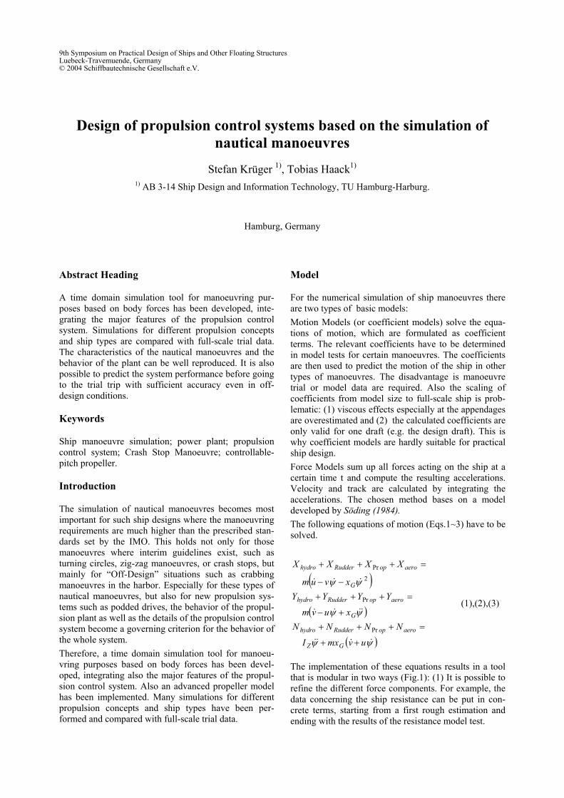
Design of propulsion control systems based on the simulation of nautical manoeuvres Stefan Krüger 1) , Tobias Haack 1) 1) AB 3-14 Ship Design and Information Technology, TU Hamburg-Harburg. Hamburg, Germany Abstract Heading A time domain simulation tool for manoeuvring pur- poses based on body forces has been developed, inte- grating the major features of the propulsion control system. Simulations for different propulsion concepts and ship types are compared with full-scale trial data. The characteristics of the nautical manoeuvres and the behavior of the plant can be well reproduced. It is also possible to predict the system performance before going to the trial trip with sufficient accuracy even in off- design conditions. Keywords Ship manoeuvre simulation; power plant; propulsion control system; Crash Stop Manoeuvre; controllable- pitch propeller. Introduction The simulation of nautical manoeuvres becomes most important for such ship designs where the manoeuvring requirements are much higher than the prescribed stan- dards set by the IMO. This holds not only for those manoeuvres where interim guidelines exist, such as turning circles, zig-zag manoeuvres, or crash stops, but mainly for “Off-Design” situations such as crabbing manoeuvres in the harbor. Especially for these types of nautical manoeuvres, but also for new propulsion sys- tems such as podded drives, the behavior of the propul- sion plant as well as the details of the propulsion control system become a governing criterion for the behavior of the whole system. Therefore, a time domain simulation tool for manoeu- vring purposes based on body forces has been devel- oped, integrating also the major features of the propul- sion control system. Also an advanced propeller model has been implemented. Many simulations for different propulsion concepts and ship types have been per- formed and compared with full-scale trial data. Model For the numerical simulation of ship manoeuvres there are two types of basic models: Motion Models (or coefficient models) solve the equa- tions of motion, which are formulated as coefficient terms. The relevant coefficients have to be determined in model tests for certain manoeuvres. The coefficients are then used to predict the motion of the ship in other types of manoeuvres. The disadvantage is manoeuvre trial or model data are required. Also the scaling of coefficients from model size to full-scale ship is prob- lematic: (1) viscous effects especially at the appendages are overestimated and (2) the calculated coefficients are only valid for one draft (e.g. the design draft). This is why coefficient models are hardly suitable for practical ship design. Force Models sum up all forces acting on the ship at a certain time t and compute the resulting accelerations. Velocity and track are calculated by integrating the accelerations. The chosen method bases on a model developed by Söding (1984). The following equations of motion (Eqs.1~3) have to be solved. ( ) ( ) ( ) ψ ψ ψ ψ ψ ψ & & & & & & & & & & & u v mx I N N N N x u v m Y Y Y Y x v u m X X X X G Z aero op Rudder hydro G aero op Rudder hydro G aero op Rudder hydro + + = + + + + − = + + + − − = + + + Pr Pr 2 Pr (1),(2),(3) The implementation of these equations results in a tool that is modular in two ways (Fig.1): (1) It is possible to refine the different force components. For example, the data concerning the ship resistance can be put in con- crete terms, starting from a first rough estimation and ending with the results of the resistance model test. 9th Symposium on Practical Design of Ships and Other Floating Structures Luebeck-Travemuende, Germany © 2004 Schiffbautechnische Gesellschaft e.V.
Transcript of Design of propulsion control systems based on the ... · PDF fileDesign of propulsion control...
Design of propulsion control systems based on the simulation of nautical manoeuvres
Stefan Krüger 1), Tobias Haack1) 1) AB 3-14 Ship Design and Information Technology, TU Hamburg-Harburg.
Hamburg, Germany
Abstract Heading
A time domain simulation tool for manoeuvring pur-poses based on body forces has been developed, inte-grating the major features of the propulsion control system. Simulations for different propulsion concepts and ship types are compared with full-scale trial data. The characteristics of the nautical manoeuvres and the behavior of the plant can be well reproduced. It is also possible to predict the system performance before going to the trial trip with sufficient accuracy even in off-design conditions.
Keywords
Ship manoeuvre simulation; power plant; propulsion control system; Crash Stop Manoeuvre; controllable-pitch propeller.
Introduction
The simulation of nautical manoeuvres becomes most important for such ship designs where the manoeuvring requirements are much higher than the prescribed stan-dards set by the IMO. This holds not only for those manoeuvres where interim guidelines exist, such as turning circles, zig-zag manoeuvres, or crash stops, but mainly for “Off-Design” situations such as crabbing manoeuvres in the harbor. Especially for these types of nautical manoeuvres, but also for new propulsion sys-tems such as podded drives, the behavior of the propul-sion plant as well as the details of the propulsion control system become a governing criterion for the behavior of the whole system. Therefore, a time domain simulation tool for manoeu-vring purposes based on body forces has been devel-oped, integrating also the major features of the propul-sion control system. Also an advanced propeller model has been implemented. Many simulations for different propulsion concepts and ship types have been per-formed and compared with full-scale trial data.
Model
For the numerical simulation of ship manoeuvres there are two types of basic models: Motion Models (or coefficient models) solve the equa-tions of motion, which are formulated as coefficient terms. The relevant coefficients have to be determined in model tests for certain manoeuvres. The coefficients are then used to predict the motion of the ship in other types of manoeuvres. The disadvantage is manoeuvre trial or model data are required. Also the scaling of coefficients from model size to full-scale ship is prob-lematic: (1) viscous effects especially at the appendages are overestimated and (2) the calculated coefficients are only valid for one draft (e.g. the design draft). This is why coefficient models are hardly suitable for practical ship design. Force Models sum up all forces acting on the ship at a certain time t and compute the resulting accelerations. Velocity and track are calculated by integrating the accelerations. The chosen method bases on a model developed by Söding (1984). The following equations of motion (Eqs.1~3) have to be solved.
( )
( )
( )ψψ
ψψ
ψψ
&&&&
&&&&
&&&
uvmxI
NNNNxuvm
YYYYxvum
XXXX
GZ
aeroopRudderhydro
G
aeroopRudderhydro
G
aeroopRudderhydro
++
=++++−
=+++−−
=+++
Pr
Pr
2
Pr
(1),(2),(3)
The implementation of these equations results in a tool that is modular in two ways (Fig.1): (1) It is possible to refine the different force components. For example, the data concerning the ship resistance can be put in con-crete terms, starting from a first rough estimation and ending with the results of the resistance model test.
9th Symposium on Practical Design of Ships and Other Floating StructuresLuebeck-Travemuende, Germany© 2004 Schiffbautechnische Gesellschaft e.V.

(2) It is possible to activate or deactivate single force components (e.g. wind).
Fig.1: Simulation Model
The focus within this paper is the integration of a new model for the simulation of the power plant and the propeller into a existing manoeuvre simulation software.
Propulsion Model
We discuss here only the new and relevant modifica-tions of the propulsion model. Within the research pro-ject the propulsion variants shown in Table 1 were ana-lysed.
Table 1: Propulsion variants
2-stroke Diesel 4-stroke Diesel Diesel-Electric Fixed Pitch Propel-ler
FPP FPP
Controllable Pitch Propeller
CPP CPP
POD with FPP
Propeller Model The propeller forces are described by KT-KQ curves as far as these curves are known. These diagrams exist for many different propellers with different pitch, diameter, and disc area ratio. The coefficients for the wake and the thrust deduction are often known either from a ves-sel of comparison, direct calculations (CFD), or model tests. These diagrams are suitable for the simulation of ship manoeuvres such as turning circles or zig-zag ma-noeuvres to compute the propeller forces in the relevant velocity range. If no trial data of a comparable propeller is available, the Wageningen B-Series is used, Van Lammeren et al. (1969). Problems arise if the propeller is not working in the Forward velocity / Forward thrust condition or if a CPP works in an off-design condition. These operating conditions occur during crash-stop manoeuvres and crabbing manoeuvres in the harbour. The implemented propeller model which overcomes this problem is explained below. For the fixed-pitch propeller, the open-water curves of the Wageningen B-Series are used if no better data is available. In addition to the standard KT-KQ curves, open-water diagrams for the operating conditions For-
ward velocity/ backwards thrust, Backward velocity/ Forward thrust, and Backward velocity/Backward Thrust (Four-quadrant Model) exist, Van Lammeren et al. (1969). The four-quadrant data of the Wageningen B-Series is also used for known propellers to describe their behaviour in the 3 non-tested quadrants. In this case, the Wageningen Curves are modified by a correc-tion function to coincide the two curves in the first quadrant, Fig.2.
Fig.2: Open-water Diagram for a Fixed Pitch Propeller
Although controllable-pitch propellers (CPP) are often not operating with their design pitch, the open-water curves are normally only available for this condition (e.g. from a model test). This is insufficient for a ma-noeuvre simulation. Initially one may be tempted to use the Wageningen Series, because they include a wide range of pitches, but CPPs behave differently if oper-ated with reduced pitch than an FPP of same average pitch. Therefore we used a propeller model which con-sists of numerically calculated open-water curves for different operating conditions (variable pitch and ad-vance coefficients). If thrust and velocity have the same orientation, a vortex model is the method of choice. For the other conditions, a momentum theory (based on Glauert) is used, which includes the recirculation effects using empirical corrections. These computations are very time consuming. To minimize the computation time during the manoeuvre simulations, a couple of open-water diagrams are calculated in advance. Propel-ler thrust and torque are then quickly determined by interpolation between these curves during the manoeu-vre simulation. In addition, correction functions are used additionally, Fig.3 and Fig.4. Pod devices are treated as fixed-pitch propellers in an angular flow, so that the angle of incident of the propel-ler corresponds to the “rudder part” of the pod, Krüger and Urban (2000).

Fig.3: Open-water curves (KQ) for a CPP
Fig.4: Open-water curves (KT) for a CPP
Propulsion Plant
Figs.5 and 6 show the model of the propulsion plant. Fig.5 shows the configuration of the implemented model of a 2-stroke diesel engine with a FPP. Fig.6 shows a 4-stroke diesel engine in combination with a CPP unit. The important parts of the power plant are described below.
Control System
The shaft governor in a FPP propulsion plant has to tune in the engine speed that corresponds to the lever posi-tion. In CPP propulsion plants, the governor has to hold the constant speed of the engine. In combinator mode, a combination of shaft speed and pitch corresponding to the combinator diagram has to be tuned in. The shaft governor is implemented as PI controller without reac-tion time. The following mathematical model is used:
startiscommand torqueninnptorque +⋅+−⋅= int)( (4)
( ) ( )1int,int, 1 −−⋅−+=− nniscommandtt ttnnnn
nn.
In addition, a hysteresis curve is implemented. This curve prevents the governor from reacting in the case of small deviations. Moreover, if a FPP is used, the shaft speed must not fall below the a certain shaft speed (idle speed) to prevent stall of engine. The pitch controller tunes in the blade angle that corre-sponds to the lever. This is done by activating and deac-tivating the hydraulic pumps to control the blade turning rate. Furthermore, illegal operating conditions have to be prevented. For example, it has to be ensured, that the
engine is not wind milling during crash stop manoeu-vres if the pitch is reduced too fast. An effective way to avoid this effect is to implement a crash-stop program which reduces the engine speed to idle speed. A combi-nator mode is also implemented in the simulation model. This means, that combinations of shaft speed and pitch value are adjusted according to the so called combinator curve as far as the combinator mode is inte-grated in the plant. The combinator curve includes the command values for shaft speed and pitch for the given lever command.
Examples
As test cases a 2 RORO-Ferries with different propul-sion concepts were chosen. Ship 1 is a single-screw vessel with a 2-stroke diesel engine and a Controllable Pitch Propeller controlled by a combinator curve. Ship 2 is a twin screw vessel with 4-stroke diesel engines and Controllable Pitch Propellers in constant rev. mode. Different manoeuvres were simulated and the results are compared with the sea trial data below.
Table 2: Ship 1 LPP 189.692 m B 26.50 m TD 6.95 m V Approx. 20000 m3 Service Speed Approx. 23 Knots Propulsion 2-stroke / CPP
Table 3: Ship 2 LPP 182.390 m B 26.00 m TD 5.7 m V Approx. 15,000 m3 Service Speed approx. 21.5 Knots Propulsion 4-stroke / CPP

MM
MLn
Shaft
Fpn
Ship
I nCmd. n
Fuel Rack Cmd.
PI - Governer
-K- Gain
p (CompressorPressure)
Fuel Cmd.
n
I
Fuell
Cut-off governor2S-DM
n
v
Mp
Fp
FPP 4-Quadrants
Lever NCmd. n nCmd.
Overload- Program
Lever Me dmKr/dt n
I
MM
Starter
Fuel
n
p
Me
dmKr/dt
2-Stroke Motor
+ +
Fig.5: Block Diagram of a 2-stroke diesel engine with FPP
MM ML n
Shaft
P/D Cmd. P/D
CPP - mechanics
np P/D* v
Mp Fp
CPP
Fp v
Ship
I
nCmd.
n
Fuel Cmd.
PI-Governer
Lever P/D act. n Fuel FuelCut
nCmd.
P/D Cmd.
I
Combinator and CPP Govenor
-K- Gain
p FuelCmd.-
n I Fuel Cut-Off Governer
4S-DM
Lever Fuel
n
p
Me 4-Stroke Engine
Fig.6: Block diagram of a 4-stroke diesel engine with CPP

Turning Circle Simulation
Fig.7: Turning Circle Ship 1: Track
Fig.8: Turning Circle Ship 1: simulated power plant
Fig.9: Turning Circle Ship 1: simulated speed
Table 4: Turning Circle Ship 1 and 2 Ship 1 Ship2 Measured Simulated Measured SimulatedTact. Diameter
541 m 502 m 537 m 472 m
Advance 579 m 524 m 444 m 504 m Figs.7~12 and Table 4 show the good agreement be-tween simulated and measured turning circle diameters. The difference (Ship 1: Tactical Diameter measured 541m; simulated 502m) is within the scope of what is reproducible during a sea trial. During the sea trial, the turning circle diameter is not only influenced by the environment (e.g. wind, sea state, shallow water) but by the actual state of the power plant. If for example the starboard turning circle is performed after the portside turning circle, it might be possible, that the engine has been overloaded and an overload protection program prevents the engine from providing the full available power. The pitch reduction is simulated precisely, Fig.11 The pitch of the outer propeller is reduced to 73%. The inner propeller has a pitch of 82 % of the design pitch, because the outer propeller is exposed to a greater cross flow than the inner propeller.
Fig.10: Turning Circle Ship 2:
Track
Fig.11: Turning Circle Ship 2: Simulated power plant

Fig.12: Turning Circle Ship 2: Simulated speed.
Crash-Stop Manoeuvre Simulation An other important manoeuvre is the crash-stop ma-noeuvre. The ship has to be stopped from maximum speed ahead. This is a crucial manoeuvre regarding the control units. Ships with power plants consisting of a 2-stroke Diesel Engine and a FPP are stopped by revers-ing the machine. So the stopping distance depends on the power of the starter (FPP) and the thermal protection unit. Ships with CPPs are stopped by reversing the blades. Figs.13~16 and Table 5 show simulated and measured data of crash-stop manoeuvres of Ship 1 (22.5 knots). Figs.13~15 and Fig.17~18 show the result of the same manoeuvre with a different plant configuration.
Fig.13: Ship 1; simulated crash-stop manoeuvre from full
ahead (22.5 kn): Track.
Table 5: Crash Stop Ship 1 with and without Crash Stop Program
Simulated With CSP
Simulated Without CSP
Meas-ured
Stopping Distance 977 m 1022 m 955 m Stopping Time 171 s 174 s Zero Pitch at 37 s 38 s 25 s The plant diagrams in Fig.14 and Fig. 16 show the ef-fect of the crash-stop program. The governor command is set to idle speed as the crash-stop command is given (lever command “full astern” from “full ahead”). This avoids the wind milling effect, and the maximum astern pitch is reached faster. This control unit reduces the simulated stopping distance from 1022 m (Fig.13) to 977m.
Fig.14: Ship 1; simulated crash-stop manoeuvre
from full ahead (22.5 kn): Power plant with CSP.
Fig.15: Ship 1; simulated crash-stop manoeuvre from full
ahead (22.5 kn): Speed with CSP
Such a program is not implemented in the power plant of Ship 2 (Fig.19~21 and Table 6). Between 15 and 40 second of the simulated trial (Figs.20) the wind milling effect is evident. Temporally the pitch has to be reduced much slower because the turbine condition of the engine has to be avoided. So the stopping distance is unneces-sary increased. A Crash Stop Program would reduce the stopping distance to 742 m (775m without CSP).
Fig.16: Ship 1; Measured power plant diagram in sea trial.
Simulations and analysis of sea trial show that the blade turning rate of the CPP control unit does not influence the stopping distance significantly. Simulated and measured behaviour of the power plant agree qualita-tively well. The calculated stopping distances are pre-dicted precisely.

Fig.17: Ship 1; simulated crash-stop manoeuvre from full ahead (22.5 kn): Power plant; without Crash-Stop Pro-
gram.
Fig.18: Ship 1; Simulated Crash stop manoeuvre from full
ahead (22.5 kn): Speed; without Crash-Stop Program.
Fig.19: Ship 2; Simulated crash-stop manoeuvre from full
ahead (20.3 kn).
Table 6: Crash Stop Ship 2 Simulated Measured Stopping Distance 775 m 887 m Stopping Time 146 s 188 s Zero Pitch at 40 s
Fig.20: Ship 2; Simulated crash-stop manoeuvre from full
ahead (20.3 kn): Power plant.
Fig.21: Ship 2; Simulated crash-stop manoeuvre from full
ahead (20.3 kn): Speed.
Conclusions
The results of the manoeuvre simulations agree well with the measured values from the sea trial. The stan-dard manoeuvres can be predicted sufficiently well. The simulation of turning circles, zig-zags and Williamson turns in the design process enables the engineer to evaluate whether his ship fulfils the requirements of the IMO and the customer without making expansive model tests. He can also estimate how the controllers have to be adjusted to guarantee the best possible manoeuvring performance. The results from the crash-stop simulation differ from measured data for several reasons. There is no knowledge about the thrust deduction during the crash stop manoeuvre. An extension of the current work shall implement a direct computation method to overcome this problem. This will allow then to compute thrust deduction coefficients in all four quadrants. Furthermore the simulation model will be integrated into different systems for nautical training in the near future. These systems with their visualisation tools will allow to use the manoeuvring model interactively. Therefore nautical instruments of different manufactur-ers have to be implemented.
References
Krüger, S.; Urban, A. (2000), Abschätzung der Manöv-
riereigenschaften von Azimuth Antrieben in der Pro-jektphase , Handbuch der Werften XXV, Hansa-Verlag
Söding, H. (1984), Bewertung der Manövriereigen-schaften im Entwurfsstadium, Jahrbuch der Schiff-bautechnischengesellschaft, Springer
Van Lammeren, W.; Van Manen, J.; Oosterverld, M. (1969), The Wageningen B-Screw Series, Trans. SNAME 77, pp.269-317