Design of physical topology and placement of equipment in...
13
IJCSNS International Journal of Computer Science and Network Security, VOL.16 No.6, June 2016 14 Manuscript received June 5, 2016 Manuscript revised June 20, 2016 Design of physical topology and placement of equipment in a hybrid optical-wireless access network Rejaul Chowdhury Khaled Almustafa, Western University, London Ontario, Canada Prince Sultan University, Riyadh, K.S.A Abstract Due to the emergence of numerous bandwidth-hungry applications, we are motivated to investigate cheaper and faster Internet access solutions to serve in a neighborhood. We concentrate on the convergence of optical and wireless networks for the deployment of Internet access networks so that we can exploit the opportunities of both technologies. We focus on network dimensioning and placement of equipment in hybrid optical-wireless access networks. A number of integrated optical-wireless architectures have been investigated for the greenfield deployment of future access networks. A novel hybrid network infrastructure, namely PON-LTE access network, has been proposed where fiber will be deployed as deeply as affordable/practical and then, wireless systems will be used to extend this connectivity to a large number of locations and ultimately connect the wire- less end users. We propose a 2- phase network design optimization scheme for greenfield deployment of PON-LTE access network infrastructure. In the first phase, we propose an integer linear programming (ILP) model which optimizes the greenfield deployment of LTE network based on the static distribution of mobile user equipment (MUE). The proposed model takes into account various physical layer constraints of LTE network and determines the optimal clustering of MUEs as well as the location of eNBs in a neighborhood. In the second phase, we propose another ILP model which determines the optimal placement of a number of integrated ONU-EPCs as well as a single AWG with respect to the location of the eNBs determined during the first phase. Our proposed scheme also facilitates the construction of an efficient physical architecture/topology of a hybrid PON-LTE access network. Computational experiments have been conducted on three different data sets consisting of 128, 256 and 512 mobile user equipment in order to evaluate the performance of the proposed scheme. Keywords: PON, WiMAX, LTE, WiFi 1. Introduction Modern society, now a days, relies heavily on the Internet for instant access to information. Although current network technologies offer affordable solutions for residential users, they still pose fundamental quality of service and bandwidth limitations, particularly for high- end business users. Moreover, most of the public Internet service providers (ISPs) still offer best effort capabilities which result in considerable bandwidth limitation and latencies. Inevitably, these factors limit a wide range of users including private industry, government, educational, and scientific institutions from effectively achieving timely information delivery over larger distances. Due to the tremendous demand for high speed data networks, we are motivated to investigate inexpensive and faster Internet access solutions which will still be scalable, resilient, and capable of achieving guaranteed performance Figure 1: PON Architecture Optical fiber enabled technologies can definitely be considered as an attractive solution for access networks to face the challenges of the new era. Optical fiber, considered as the last step for the future all-optic network revolution, has already been deployed in the backbone and the metropolitan networks. It is now penetrating into the access network domain mitigating the bandwidth bottleneck between the end users and the high capacity backbone network. Optical access networks, often termed as FTTX (Fiber-to-the Home/Premises/Curb), may consist of either active or passive architecture [1]. An active architecture is usually established by deploying a remote curb switch close to the neighborhood, a single fiber from the central office (CO) to a switch, and a number of short branching fibers from the switch to each end user. But such an active star architecture does not attract ISPs as the curb switch requires electric power which is the most significant operational cost for the local ISP. On the other hand, passive architectures draw sensational attention not only from the ISPs but also from the researcher communities around the world as these are the most cost- effective solutions for optical access networks. Passive
Transcript of Design of physical topology and placement of equipment in...

IJCSNS International Journal of Computer Science and Network Security, VOL.16 No.6, June 2016
14
Manuscript received June 5, 2016 Manuscript revised June 20, 2016
Design of physical topology and placement of equipment in a hybrid optical-wireless access network
Rejaul Chowdhury Khaled Almustafa, Western University, London Ontario, Canada Prince Sultan University, Riyadh, K.S.A
Abstract Due to the emergence of numerous bandwidth-hungry applications, we are motivated to investigate cheaper and faster Internet access solutions to serve in a neighborhood. We concentrate on the convergence of optical and wireless networks for the deployment of Internet access networks so that we can exploit the opportunities of both technologies. We focus on network dimensioning and placement of equipment in hybrid optical-wireless access networks. A number of integrated optical-wireless architectures have been investigated for the greenfield deployment of future access networks. A novel hybrid network infrastructure, namely PON-LTE access network, has been proposed where fiber will be deployed as deeply as affordable/practical and then, wireless systems will be used to extend this connectivity to a large number of locations and ultimately connect the wire- less end users. We propose a 2-phase network design optimization scheme for greenfield deployment of PON-LTE access network infrastructure. In the first phase, we propose an integer linear programming (ILP) model which optimizes the greenfield deployment of LTE network based on the static distribution of mobile user equipment (MUE). The proposed model takes into account various physical layer constraints of LTE network and determines the optimal clustering of MUEs as well as the location of eNBs in a neighborhood. In the second phase, we propose another ILP model which determines the optimal placement of a number of integrated ONU-EPCs as well as a single AWG with respect to the location of the eNBs determined during the first phase. Our proposed scheme also facilitates the construction of an efficient physical architecture/topology of a hybrid PON-LTE access network. Computational experiments have been conducted on three different data sets consisting of 128, 256 and 512 mobile user equipment in order to evaluate the performance of the proposed scheme. Keywords: PON, WiMAX, LTE, WiFi
1. Introduction
Modern society, now a days, relies heavily on the Internet for instant access to information. Although current network technologies offer affordable solutions for residential users, they still pose fundamental quality of service and bandwidth limitations, particularly for high-end business users. Moreover, most of the public Internet service providers (ISPs) still offer best effort capabilities which result in considerable bandwidth limitation and
latencies. Inevitably, these factors limit a wide range of users including private industry, government, educational, and scientific institutions from effectively achieving timely information delivery over larger distances. Due to the tremendous demand for high speed data networks, we are motivated to investigate inexpensive and faster Internet access solutions which will still be scalable, resilient, and capable of achieving guaranteed performance
Figure 1: PON Architecture
Optical fiber enabled technologies can definitely be considered as an attractive solution for access networks to face the challenges of the new era. Optical fiber, considered as the last step for the future all-optic network revolution, has already been deployed in the backbone and the metropolitan networks. It is now penetrating into the access network domain mitigating the bandwidth bottleneck between the end users and the high capacity backbone network. Optical access networks, often termed as FTTX (Fiber-to-the Home/Premises/Curb), may consist of either active or passive architecture [1]. An active architecture is usually established by deploying a remote curb switch close to the neighborhood, a single fiber from the central office (CO) to a switch, and a number of short branching fibers from the switch to each end user. But such an active star architecture does not attract ISPs as the curb switch requires electric power which is the most significant operational cost for the local ISP. On the other hand, passive architectures draw sensational attention not only from the ISPs but also from the researcher communities around the world as these are the most cost-effective solutions for optical access networks. Passive
15
IJCSNS International Journal of Computer Science and Network Security, VOL.16 No.6, June 2016
15
architectures are deployed in passive optical networks (PONs) which reduce the operational cost significantly by replacing the active switch by a passive optical power splitter/combiner. In a typical PON architecture, there is an optical line terminal (OLT) at the CO of the ISP, a number of optical network units (ONUs), one or multiple passive switching equipment placed in a remote terminal (RT) between the OLT and the ONUs. The ONUs are located either at end user premises resulting in FTTPC/ FTTH/FTTB (Fiber-to-the-PC/Home/Building) solutions or at the curb site in case of a FTTC (Fiber- to-the-Curb) architecture, see Figure 1 for an illustration. In a typical PON, the presence of only passive elements from the OLT to the ONUs makes it relatively fault tolerant and decreases its operational and maintenance costs once the infrastructure has been laid down. PONs are usually built following either time sharing principle known as time division multiplexed PON (TDM PON) or spectrum sharing principle recognized as wavelength division multiplexed PON (WDM PON) [2]. In a TDM PON, the RT consists of passive optical power splitters. In a WDM PON, the RT consists of arrayed waveguide gratings (AWGs). The characteristic of a splitter is different than that of an AWG as the former equipment splits the optical power whereas latter equipment multiplexes/de-multiplexes optical wavelengths. Recently, the research community proposes hybrid PONs which embraces both TDM PON and WDM PON technologies to avail the advantages of both technologies [3] [4]. In such a PON, a splitter (in case of TDM PON) or an AWG (in case of WDM PON) can serve as the RT. While the wireline solutions for the access networks are dominating the mainstream, wireless solutions are fairly recent phenomenon representing divergent and challenging technology. Recently, LTE (Long Term Evolution), WiMAX (Worldwide Interoperability for Microwave Access) and Wi-Fi (Wireless Fidelity) have evolved as promising wireless access networks. LTE is the latest standard in mobile as well as wireless access network technology which combines the high data rate local area network with the high mobility cellular net- work. The infrastructure and elements of LTE network are termed as Evolved Packet System (EPS) which consists of Evolved Packet Core (EPC) and Evolved Universal Terrestrial Ra- dio Access Network (E-UTRAN). The E-UTRAN operates through single node architecture known as E-UTRAN Node B (eNB) which communicates with the EPC and other eNBs. The elements of EPC are Mobility Management Entity (MME), User Plane Entity (UPE), Serving Gateway (S-GW), Home Subscriber Server (HSS), Packet Data Network Gateway (PDN GW), and Policy and Charging Rules Function (PCRF) Server etc. The architecture of a WiMAX system consists of two parts: A number of WiMAX base stations (BSs) and
hundreds of WiMAX receivers per base station which are referred to as subscriber station (SS) or customer premise equipment (CPE). In WiFi technology, any device containing the functionality of the 802.11 protocol is usually defined as a station; a group of stations that can communicate with one another under the direct control of a single coordination function (distributed coordinate function [DCF] or point coordinate function [PCF]) is termed as a basic service set (BSS); the geographic area covered by the BSS is known as the basic service area (BSA) [5].The fundamental building block of WiFi architecture supports the following two topologies [6]: Independent basic service set (IBSS) and Extended service set (ESS) networks. IBSS is an ad hoc network in which self-managed stations are grouped under the umbrella of a single BSS without the aid of any administrator. IBSS is considered as a limited range network due to its single BSS constraint. On the other hand, ESS is an infrastructure network which requires a central authority known as Access Point (AP) to manage the network and to provide specific wireless services to the users. ESS is formed by integrating together multiple BSSs using a common distribution system (DS) in which APs function as the integration points required for network connectivity between multiple BSSs. In this paper, we concentrate on the convergence of optical and wireless networks for the deployment of Internet access networks so that we can exploit the opportunities of both technologies. We focus on network dimensioning and placement of equipment in hybrid optical-wireless Access Networks. A number of integrated optical-wireless architectures have been investigated for the greenfield deployment of future access networks. To implement a hybrid optical-wireless access network, a hybrid network infrastructure has been proposed where fiber will be deployed as deeply as affordable/practical and then, wireless systems will be used to extend this connectivity to a large number of locations and ultimately connect the wireless end users. The paper is organized as follows. In Section 2, we summarize the literature related to network planning and the placement of equipment in a optical-wireless access network. In Section 3, we explore a number of optical-wireless access network architectures as well as provide a concise statement of the optical-wireless deployment problem and describe the possible optimization process for finding suitable location of the equipment in such a hybrid network. Section 4 describes our proposed 2-phase solution scheme. Our proposed -sum based integer linear programming (ILP) formulation (i.e., Model I), for the placement of eNBs, is illustrated in Section 5. We also present another ILP formulation (i.e., Model II) in Section 6 which determines the location of integrated ONU-EPCs as well as the AWG. Computational results and analysis are presented in Section 7. Conclusions are drawn in the last section
IJCSNS International Journal of Computer Science and Network Security, VOL.16 No.6, June 2016 16
2. Related Work
Several heuristics and ILP formulations have been reported for network planning problem in PONs (e.g., [7], [8],[9], [10], [11],[12],[13], [14], also [30]-[37]). In [15], Shami et al. propose a novel dynamic scheduling algorithm to facilitate different QoS in Ethernet PON(EPON). Their proposed algorithm minimizes packet delay as well as jitter for delay variation sensitive traffic. Similarly, significant number of research activities have been conducted on the designing of an efficient optical-wireless access network infrastructure. In our preliminary work[16], we propose an ILP model for the placement of eNBs with respect to mobile user equipment. Sarkar et al. [17] investigate the problem of efficient placement of multiple ONUs in a hybrid wireless optical broadband access network (WOBAN). In this paper, the authors assume that the ONUs will also serve as BSs for the wireless portion of the hybrid network. But they do not consider at all the design aspects of the front-end wireless access networks such as transmission power, coverage region, signal quality and interference of wireless BSs. Moreover, the solution of greedy algorithm may get stuck in the local minimum of the problem domain. Sarkar et al. [18] further elaborate the problem of placement of ONUs in a WOBAN infrastructure with minimum network cost (minimum distance). They apply two combi- natorial techniques namely, simulated annealing (SA) and hill-climbing (HC) to obtain the globally optimum locations of multiple ONUs. But the authors neither take into account the design aspects of the wireless front end nor focus on the convergence of ONU and BS. They did not mention about how the number of required ONUs can be determined. Moreover, it is not guaranteed that SA and HC approach will produce globally optimum solution. Sarkar et al. [19] investigate the problem of the placement of BSs and ONUs in a WOBAN environment. They formulate the problem as a “Mixed Integer Programming (MIP)” model. But the authors do not describe the strategy of identifying the groups of BSs in which all BSs of a group should be supported by a single ONU. Moreover, the proposed algorithm does not have any scheme to determine the optimum locations of the ONUs required to satisfy the traffic demands from BSs. Sarkar et al. [20] [21] propose and investigate the characteristics of the Delay-Aware Routing Algorithm(DARA) in order to handle packet delay in the wireless front end of the WOBAN. The authors claim that DARA minimizes average packet delay, generates less congestion, and improves load balancing in comparison with traditional routing algorithms. Sarkar et al. [20] proposed Risk-and-Delay-Aware Routing algorithm (RADAR) for the wireless front end of the WOBAN. RADAR can tackle not only the packet delay but also the
packet loss due to multiple failure scenarios. It can be concluded that RADAR can provide protection for both the front end wireless mesh and back end the passive optical network (PON) of the hybrid wireless optical access network. Sarkar et al. [22] discuss the challenging factors for designing the hybrid wireless-optical broadband access network. First, they reviewed the algorithms proposed in [17], [18], [19] for the optimum placement of ONUs in the hybrid access network. Later, they investigate and compare the performances of several routing algorithms, namely Minimum-Hop and Shortest Path Routing Algorithms (MHRA and SPRA), Predictive-Throughput Routing Algorithm (PTRA), Delay-Aware Routing Algorithm(DARA), and Risk-and-Delay-Aware Routing Algorithm for the wireless front end of the proposed hybrid network. Sarkar et al. [23] summarize their research activities related to the placement of equipment in WOBAN. They review greedy, Simulated Annealing, and Hill Climbing algorithms for the optimum placement of ONUs. The authors calculate the network deployment cost for PONs, WOBAN with WiMAX at the front end, and also WOBAN with WiFi. But the authors do not clearly describe the architecture of the front end of WOBAN, for example the required number and locations of deployed WiFi APs or WiMAX APs/BSs are not mentioned in the scenario of a given neighborhood. They do not devise any technique to find the optimum number for the ONUs and APs/BSs required to satisfy the bandwidth requests from all the users. They do not apply any clustering technique to divide the users into several groups such that each group of users can be served by an AP efficiently. They connect each ONU with only one BS resulting in wastage of huge bandwidth of an ONU, as each ONU has significantly higher bandwidth capacity compared to an AP/BS. Finally, the authors propose a Combined Heuristic (CH) for joint optimization in a “greenfield” deployment of WOBAN that focuses on the placement of APs (on the basis of interference) in the front end, placement of ONUs (as returned by the greedy algorithm), and the minimum-cost fiber layout from OLT to the ONUs in the back end simultaneously. The authors do not specify how minimum spanning tree (MST) is constructed from the OLT to all the ONUs. Moreover, it should be mentioned that the topology of PON technology is implemented by Steiner tree not by MST, this fact creates ambiguity about the effectiveness of this heuristic. Lin et al. [24] investigate the dimensioning and site planning (DSP) of integrated PON and wireless cooperative networks (WCN) for fixed mobile coverage (FMC). They propose a mathematical formulation of the DSP problem with the objective of minimizing the over- all infrastructure cost for integrated PON-WCN

17
IJCSNS International Journal of Computer Science and Network Security, VOL.16 No.6, June 2016
17
architecture and determining the location of network entities in such a network architecture. The proposed formulation of the DSP aims to provide better performance, including ONU-BS placement, splitter placement, fiber deployment and BS-user association while incorporating inter-cell cooperative transmission. Due to computational complexity, the authors decompose the DSP problem into two sub problems: (i) Subproblem 1 to minimize the total infrastructure cost for ONU-BS deployment, (ii) Subproblem 2 (a MILP) to minimize the total cost for PON deployment. As the Subproblem 1 is a mixed integer nonlinear program (MINLP), the authors reformulate it into a solvable MILP. Simulation results show that the proposed optimization frame work reduces the infrastructure cost significantly while improving spectral efficiency and scalability in capacity enhancement under cooperative service provisioning. Mirahmadi and Shami [25] propose a novel traffic-prediction-assisted scheduling algorithm for hybrid optical wireless networks which significantly improves the Quality of Service (QoS) on such a non-homogeneous network. Their proposed scheduling mechanism predicts the incoming traffic to the ONUs by extracting the internal information of the wireless scheduler which eventually leads to traffic-aware dynamic bandwidth allocation (DBA). The authors propose DBA algorithm which executes in two phases: (i) inter-ONU scheduling, performed at the OLT (ii) intra-ONU scheduling, performed at each ONU. Their proposed algorithm performs well in high load conditions when the delay can be decreased by a factor of two while maintaining high throughput. Ahmed and Shami [26] propose a new architecture for an integrated metro-access network, namely RPR(resilient packet ring)-EPON-WiMAX, which connects an optical metro ring network with a number of hybrid optical-wireless access networks. They suggest a routing algorithm and a MAC (media access control) protocol which includes a scheduler, DBA, and distributed admission control. The proposed MAC protocol distributes its functionalities over different parts of the architecture. The proposed routing algorithm takes into account the conditions over the entire network such that the delay is minimized and the load is balanced. In the literature, the convergence challenges of optical and wireless access technology in a hybrid optical-wireless access network are not clearly described. Moreover, previous research activities do not take into account the constraints of specific technologies, e.g. WiMAX or WiFi or LTE, while developing the mathematical models or implementing the heuristic algorithms for a hybrid access network. It is obvious that placement of equipment in a network environment is dependent on the constraints of the equipment of a specific technology. The literature also
lacks the research activities on how to determine the optimum number of equipment in a hybrid access network. Again, while investigating the hybrid optical wireless access networks exploiting passive optical network (PON) technology in the back-end and WiMAX (802.16j standard)technology in the front end, previous research activities do not consider any clustering techniques either for grouping the users to be served by one SS, or for grouping the SSs to be served by one RS (relay station), or for grouping the RSs to be served by one BS, or for grouping the BSs to be served by one ONU, or for grouping the ONUs to be served by one splitter/AWG, or for grouping the splitters/AWGs to be served by one OLT (optical line terminal). To the best of our knowledge, there is no published work which integrates PON and LTE technologies as potential candidates for the hybrid optical wireless access networks. These above mentioned factors have motivated us to focus on designing the best possible architectures of hybrid optical wireless access networks.
3. Problem Statement and Optimization Process
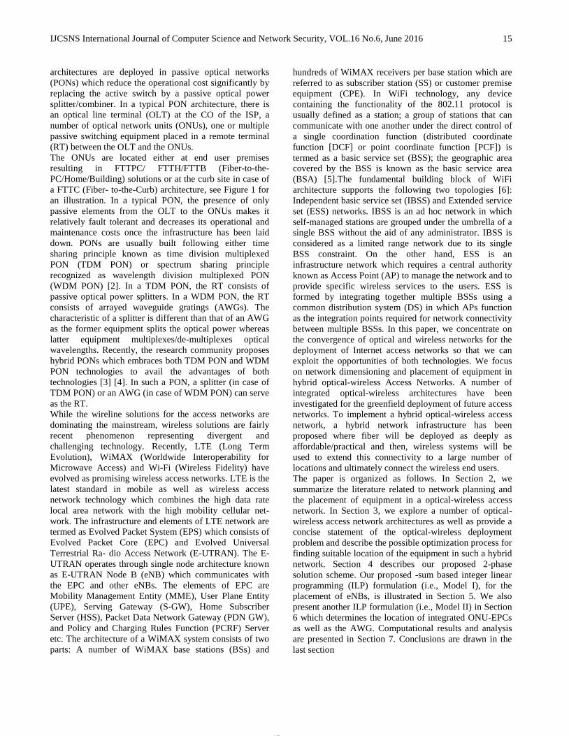
We intend to develop network planning tools in order to optimize the dimensioning of the optical and wireless parts of a hybrid access network so that we can decide efficiently about where to take over from the optical back end and to start the wireless front end. Our aim is to determine the optimal location of equipment in a hybrid optical-wireless access network. We also plan to devise an efficient optical-wireless access network infrastructure. We have taken into account a number of hybrid optical-wireless access network architectures: (i) PON integrated with WiFi technology (Architecture I), (ii) PON integrated with WiMAX technology (Architecture II), (iii) PON integrated with both WiMAX and WiFi technologies (Architecture III) (iv) PON integrated with LTE and WiFi technology (Architecture IV). Each network architecture can be described as below. In Architecture I, as shown in Figure 2, the wireless stations are organized in a number of BSS (basic service set) where each station within the BSS is managed by an AP (access point) as specified by the IEEE 802.11 infrastructure-mode network, the APs are connected to the ONUs, the splitter/AWG, and the OLT in sequence. Based on such an architecture, the number of BSSs and the locations of corresponding APs satisfying the constraints, such as the bandwidth requests from the users, transmission range of APs can be determined. As each ONU connects a number of APs, the optimum number and locations of ONUs can be determined so that all the APs are covered. Finally, based on the locations of ONUs, the
IJCSNS International Journal of Computer Science and Network Security, VOL.16 No.6, June 2016 18
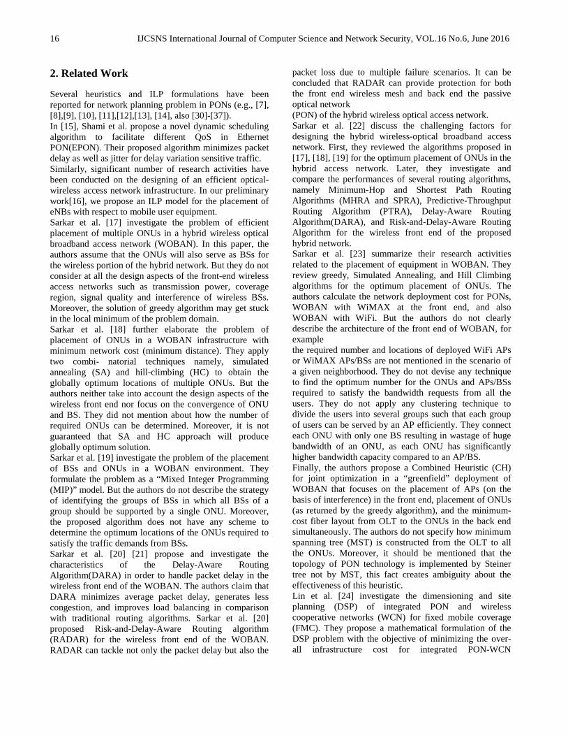
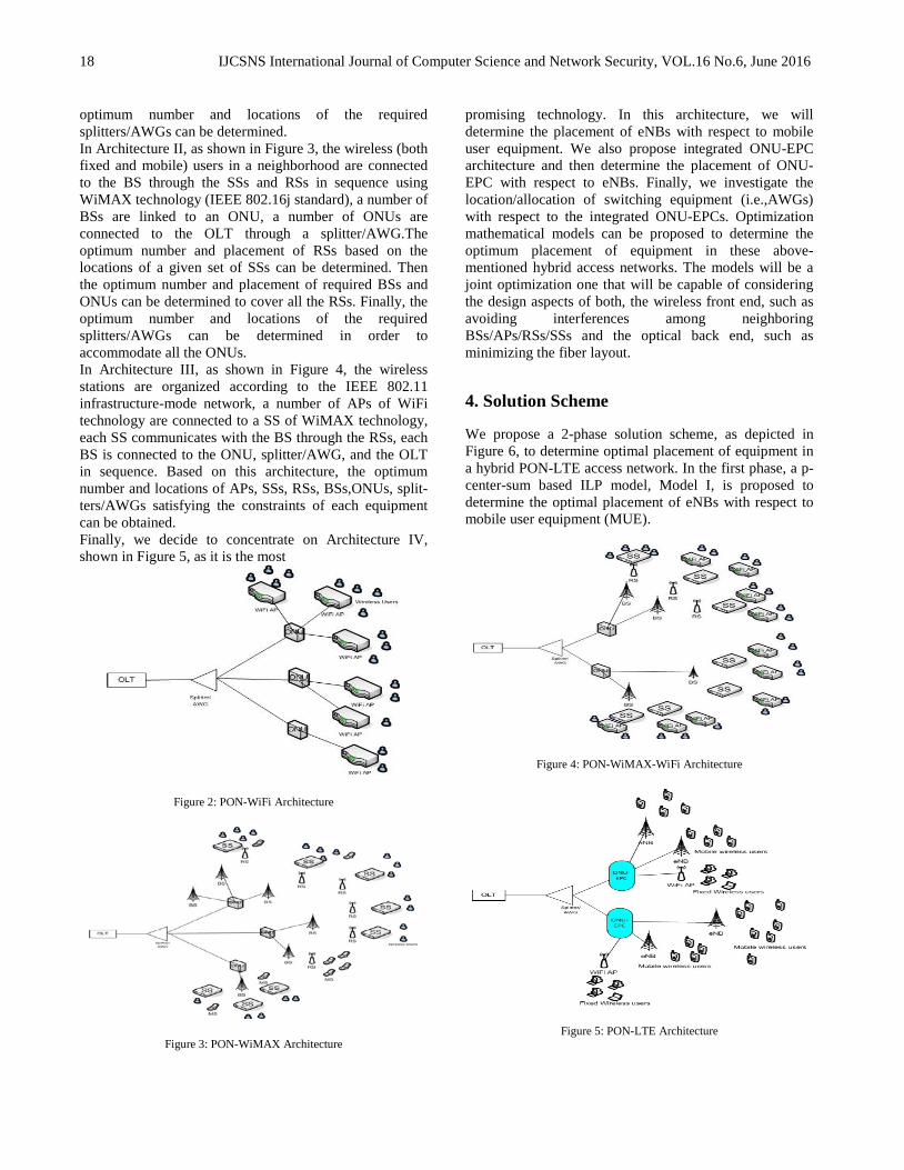
optimum number and locations of the required splitters/AWGs can be determined. In Architecture II, as shown in Figure 3, the wireless (both fixed and mobile) users in a neighborhood are connected to the BS through the SSs and RSs in sequence using WiMAX technology (IEEE 802.16j standard), a number of BSs are linked to an ONU, a number of ONUs are connected to the OLT through a splitter/AWG.The optimum number and placement of RSs based on the locations of a given set of SSs can be determined. Then the optimum number and placement of required BSs and ONUs can be determined to cover all the RSs. Finally, the optimum number and locations of the required splitters/AWGs can be determined in order to accommodate all the ONUs. In Architecture III, as shown in Figure 4, the wireless stations are organized according to the IEEE 802.11 infrastructure-mode network, a number of APs of WiFi technology are connected to a SS of WiMAX technology, each SS communicates with the BS through the RSs, each BS is connected to the ONU, splitter/AWG, and the OLT in sequence. Based on this architecture, the optimum number and locations of APs, SSs, RSs, BSs,ONUs, split- ters/AWGs satisfying the constraints of each equipment can be obtained. Finally, we decide to concentrate on Architecture IV, shown in Figure 5, as it is the most
Figure 2: PON-WiFi Architecture
Figure 3: PON-WiMAX Architecture
promising technology. In this architecture, we will determine the placement of eNBs with respect to mobile user equipment. We also propose integrated ONU-EPC architecture and then determine the placement of ONU-EPC with respect to eNBs. Finally, we investigate the location/allocation of switching equipment (i.e.,AWGs) with respect to the integrated ONU-EPCs. Optimization mathematical models can be proposed to determine the optimum placement of equipment in these above-mentioned hybrid access networks. The models will be a joint optimization one that will be capable of considering the design aspects of both, the wireless front end, such as avoiding interferences among neighboring BSs/APs/RSs/SSs and the optical back end, such as minimizing the fiber layout.
4. Solution Scheme
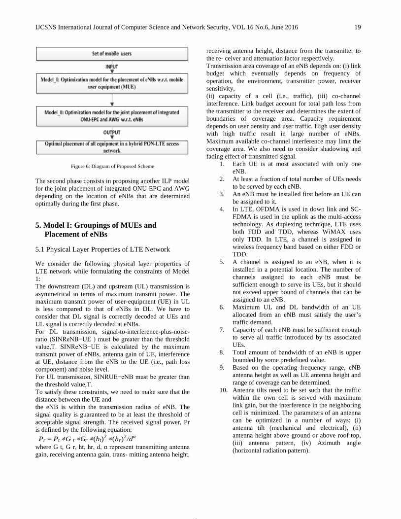
We propose a 2-phase solution scheme, as depicted in Figure 6, to determine optimal placement of equipment in a hybrid PON-LTE access network. In the first phase, a p-center-sum based ILP model, Model I, is proposed to determine the optimal placement of eNBs with respect to mobile user equipment (MUE).
Figure 4: PON-WiMAX-WiFi Architecture
Figure 5: PON-LTE Architecture
19
IJCSNS International Journal of Computer Science and Network Security, VOL.16 No.6, June 2016
19
Figure 6: Diagram of Proposed Scheme
The second phase consists in proposing another ILP model for the joint placement of integrated ONU-EPC and AWG depending on the location of eNBs that are determined optimally during the first phase.
5. Model I: Groupings of MUEs and Placement of eNBs
5.1 Physical Layer Properties of LTE Network
We consider the following physical layer properties of LTE network while formulating the constraints of Model 1: The downstream (DL) and upstream (UL) transmission is asymmetrical in terms of maximum transmit power. The maximum transmit power of user-equipment (UE) in UL is less compared to that of eNBs in DL. We have to consider that DL signal is correctly decoded at UEs and UL signal is correctly decoded at eNBs. For DL transmission, signal-to-interference-plus-noise-ratio (SINReNB−UE ) must be greater than the threshold value,T. SINReNB−UE is calculated by the maximum transmit power of eNBs, antenna gain of UE, interference at UE, distance from the eNB to the UE (i.e., path loss component) and noise level. For UL transmission, SINRUE−eNB must be greater than the threshold value,T. To satisfy these constraints, we need to make sure that the distance between the UE and the eNB is within the transmission radius of eNB. The signal quality is guaranteed to be at least the threshold of acceptable signal strength. The received signal power, Pr is defined by the following equation: Pr = Pt ∗ G t ∗ G r ∗ (ht)2 ∗ (hr)2/dα
where G t, G r, ht, hr, d, α represent transmitting antenna gain, receiving antenna gain, trans- mitting antenna height,
receiving antenna height, distance from the transmitter to the re- ceiver and attenuation factor respectively. Transmission area coverage of an eNB depends on: (i) link budget which eventually depends on frequency of operation, the environment, transmitter power, receiver sensitivity, (ii) capacity of a cell (i.e., traffic), (iii) co-channel interference. Link budget account for total path loss from the transmitter to the receiver and determines the extent of boundaries of coverage area. Capacity requirement depends on user density and user traffic. High user density with high traffic result in large number of eNBs. Maximum available co-channel interference may limit the coverage area. We also need to consider shadowing and fading effect of transmitted signal.
1. Each UE is at most associated with only one eNB.
2. At least a fraction of total number of UEs needs to be served by each eNB.
3. An eNB must be installed first before an UE can be assigned to it.
4. In LTE, OFDMA is used in down link and SC-FDMA is used in the uplink as the multi-access technology. As duplexing technique, LTE uses both FDD and TDD, whereas WiMAX uses only TDD. In LTE, a channel is assigned in wireless frequency band based on either FDD or TDD.
5. A channel is assigned to an eNB, when it is installed in a potential location. The number of channels assigned to each eNB must be sufficient enough to serve its UEs, but it should not exceed upper bound of channels that can be assigned to an eNB.
6. Maximum UL and DL bandwidth of an UE allocated from an eNB must satisfy the user’s traffic demand.
7. Capacity of each eNB must be sufficient enough to serve all traffic introduced by its associated UEs.
8. Total amount of bandwidth of an eNB is upper bounded by some predefined value.
9. Based on the operating frequency range, eNB antenna height as well as UE antenna height and range of coverage can be determined.
10. Antenna tilts need to be set such that the traffic within the own cell is served with maximum link gain, but the interference in the neighboring cell is minimized. The parameters of an antenna can be optimized in a number of ways: (i) antenna tilt (mechanical and electrical), (ii) antenna height above ground or above roof top, (iii) antenna pattern, (iv) Azimuth angle (horizontal radiation pattern).

IJCSNS International Journal of Computer Science and Network Security, VOL.16 No.6, June 2016 20
5.2 Mathematical Formulation
We exploit the mathematical formulation of the p-center problem to determine the location of eNBs w.r.t. mobile user equipment (MUE). In a p-center problem[27],[28], p number of service facilities are allocated to a number of demand nodes such that the maximum distance between a demand node and its corresponding service facility is minimized. In Model I, based on standard p-center problem, MUEs and eNBs are considered as demand nodes and service facilities respectively. Here, the value of p implies the total number of clusters of MUEs as well as the total number of eNBs. In this phase, the location and number of eNBs are determined. By varying the value of p, we can obtain different groupings of MUEs.
5.2.1Notations
Set of mobile user equipment V MUE = MUE1, MUE2, · · · , MUEn. A set P of discrete locations, indexed by p, such that: P = PeNB ∪ PMUE where the following locations are assumed to be known: (i) PMUE = {pMUE1 , pMUE2 , . . . , pMUEn}, the MUE locations, and (ii) PeNB the set of candidate locations for eNBs. The distance between a MUE i and a potential eNB location p is denoted by dip and N (P -value) represents the total number of eNBs to be placed. Ip,pr represents the channel interference factor between two neighboring eNBs located at p and pt respectively. B indicates a large number. Ti denotes the amount of requested bandwidth by a MUE, i ∈ pMUE . φ(Di,p) designates the supported bandwidth of MUE i corresponding to its distance Di,p from an eNB located at P , p ∈ PeNB M cp represents maximum traffic capacity of an eNB located at P where p ∈ PeNB
5.2.2Variables
- Zi represents the maximum distance between a MUE at location i and an eNB inside a group where i ∈ PMUE .
- Xp is a decision variable such that xp = 1 if an eNB is located at site p and 0 otherwise where p ∈ PeNB .
- Yi,p is a decision variable such that Yi,p = 1 if a MUE i is served by an eNB located at site p and 0 otherwise where i ∈ PMUE , p ∈ PeNB .
- Cp is a decision variable such that Cj,p = 1 if channel j is assigned to an eNB located at p ∈ PeNB where j ∈ F and F represents a set of channels.
5.2.3 Objective
(2) The maximum distance between a MUE and an eNB within a group needs to be minimized.
(3) The MUEs will be clustered into N number of groups, i.e., N number of eNBs will be placed.
(4) Each MUE will be assigned to only one eNB.
(5) At most f (f < 1) fraction of total number of MUEs can be served by each eNB.
(6) eNB Installation Constraints: MUEs can be associated only to those sites at which the eNBs have been located.
(7) For each group, the average distance from an eNB to all MUEs should be within a threshold (e.g.max-avg-val) value and the distance between an MUE and its corresponding equipment should not exceed maximum transmission radius (e.g.max rad val) value
(8)
(9) Channel Assignment Constraints: The number of channels assigned to each eNB should be large enough to serve its all MUEs.
(10) An eNB must be installed first before a channel is assigned to the corresponding eNB.
(11) The number of channels assigned to an eNB should not exceed the upper bound of channels (i.e., Uchannel) that can be assigned to any eNB.
(12) Capacity Constraints of eNBs:
21
IJCSNS International Journal of Computer Science and Network Security, VOL.16 No.6, June 2016
21
Maximum supported bandwidth for a MUE is inversely proportional to distance from the eNB. A MUE’s traffic demand should be less than the maximum supported bandwidth of the corresponding MUE with respect to its distance from the eNB.
Ti ≤ φ(Di,p)Yi,p p ∈ PeNB , i ∈ PMUE . (13) Total amount of bandwidth allocated for all MUEs served by a single eNB should be less than the maximum capacity of the corresponding eNB.
(14)
Co-channel Interference Constraint: Total amount of co-channel interference among neighboring eNBs should be less than threshold value of channel interference ratio (CIR). The
following constraint enforces that when Cp = 1, total co-channel interference for an eNB should be
less than CIR; again Cp = 0 j j implies that total co-channel interference can be an arbitrarily large number.
(15) where R.H.S. calculates total co-channel interference caused by neighboring eNBs experi- enced at an eNB located at p.
6. Model II: Placement of integrated ONU-EPC and AWG w.r.t. eNBs
6.1 Mathematical Formulation
We perform the placement of a number of integrated ONU-EPCs and a single AWG based on the location of the eNBs determined with the aid of Model I.
6.1.1. Notations
Location Parameters A set P of discrete locations, such that: P ∈ {P ∪ P ∪ POE ∪ PeNB}, where the following locations are assumed to be known: (i) P, the OLT location, (ii) PeNB = {peNB1 , peNB2 , . . . , peNBn}, the eNB locations, (iii) P the set of potential candidate locations for the AWG, and (iii) POE the set of potential candidate locations for the integrated ONU- EPC. As all these locations are known, it is easy to determine the pairwise distances Dp,q .
6.1.2 Cost Parameters
We denote by k/k OE the cost of a AWG/integrated ONU-EPC with k ∈ K output ports, K ∈ {2, 4, 8, 16, 32, 64}. Let be the cost of the fiber and trenching cost per kilometer. COSTeNB and NUMeNB represent the cost of an eNB and the total number of eNBs determined in Model I. Our optimization model excludes the cost of the OLT as it is obviously installed at the CO.
6.1.3 Variables
- ak ∈ {0, 1} is a decision variable such that ak
= 1 if an AWG with k ∈ K output ports, p p
K ∈ {2, 4, 8, 16, 32, 64} is placed at location p ∈ P.
- o ek ∈ {0, 1} is a decision variable such that o ek = 1 if an integrated ONU-EPC with
q q
k ∈ K output ports is placed at location q ∈ POE .
- Ap,q ∈ {0, 1} is a decision variable such that Ap,q = 1 if there is a link between location p and q where p ∈ {P ∪ P ∪ POE} and q ∈ {P ∪ POE ∪ PeNB}
6.1.4Objective
The objective function corresponds to the minimization of deployment cost of optical fiber and equipment from the OLT to the eNBs by finding the optimal location of the equipment while satisfying the technological constraints. It is defined as the minimization of the following equation:
(16)
6.1.5 Constraints
Equipment Location Constraints An AWG will be placed in the proposed architecture.
(17)
Each location can contain at most one integrated ONU-EPC.

IJCSNS International Journal of Computer Science and Network Security, VOL.16 No.6, June 2016 22
(18)
Total number of ONU-EPCs will be at most the number of output ports of the corresponding AWG.
(19) Topology Constraints In the proposed hybrid PON-LTE access network architecture, an OLT will be the root which will connect in turn an AWG, a number of integrated ONU-EPCs and eNBs. An OLT will be connected to a single AWG.
(20) The OLT cannot be directly connected either to an ONU-EPC or to an eNB
(21)
(22) There should be atmost one link that will connect each integrated ONU-EPC with the corresponding AWG.
(23) Each eNB must be connected to only one integrated ONU-EPC.
(24) All integrated ONU-EPCs must connect to the same AWG such that the ONU-EPC is connected to the eNBs and the AWG is connected to the OLT.
(25)
The constraint (25) is nonlinear. In order to linearize it, we add a new variable lOLT = lOLT,p lp,q , and the following constraints:
(26)
(27)
(28) Constraints Relating Equipment Location and Topology There will be incoming/outgoing links
from an equipment (i.e., AWG/ONU-EPC) if the corresponding equipment is placed in a location.
(29)
(30)
(31) Each integrated ONU-EPC can connect a number of eNBs depending on the number of output ports supported by the corresponding ONU-EPC.
(32)
The number of output ports of an AWG needs to be greater than the number of outgoing links that are connected to the integrated ONU-EPCs.
(33) Total number of outgoing links from an AWG should be equal to the total number of integrated ONU-EPCs.
(34) Attenuation Constraints Maximum allowable signal power loss from the OLT to each eNB should be less than 20 dB. Total signal loss experienced at an eNB is given by: lossr = lossr + lossr + loss + loss(35)
where lossr is the signal loss on the fiber to reach the eNB located at r, loss is the loss provoked by going through the equipment, loss is total insertion loss for all the nodes on the link, loss is a power margin to ensure that the calculation of the total loss is within the power budget range. The last two losses have a constant value. To calculate the first two losses, we introduce the variable x lossr to evaluate the total attenuation to reach the eNB located at r, r ∈ PeNB . We assume a loss of 0.2dB/km to calculate lossr and let be the attenuation factor of the which is independent of the number of outputs of .
23
IJCSNS International Journal of Computer Science and Network Security, VOL.16 No.6, June 2016
23
(36) The fourth element of the summation in (36) is nonlinear. In order to linearize it, we add one new variable llp,q,r = lp,q lq,r and the following constraints:
(37)
(38)
(39) We want the total loss for every eNB not to exceed 20 decibels:
(40)
7. Computational Results and Analysis
We implement our 2-phase solution scheme for the greenfield deployment of PON-LTE access network using the Optimization Programming Language (OPL) platform. Integer linear program (ILP) is solved using the CPLEX package. In the first phase, we implement Model I described in Section 5. This model determines the optimal groupings of MUEs to be served by a common eNB. We conduct our experiments with three different data sets consisting of 128, 256, and 512 MUEs respectively. We consider 60 candidate/potential locations for the placement of the eNBs. Location of the MUEs and the candidate equipment are randomly generated in a 40 × 80 km2 square grid.
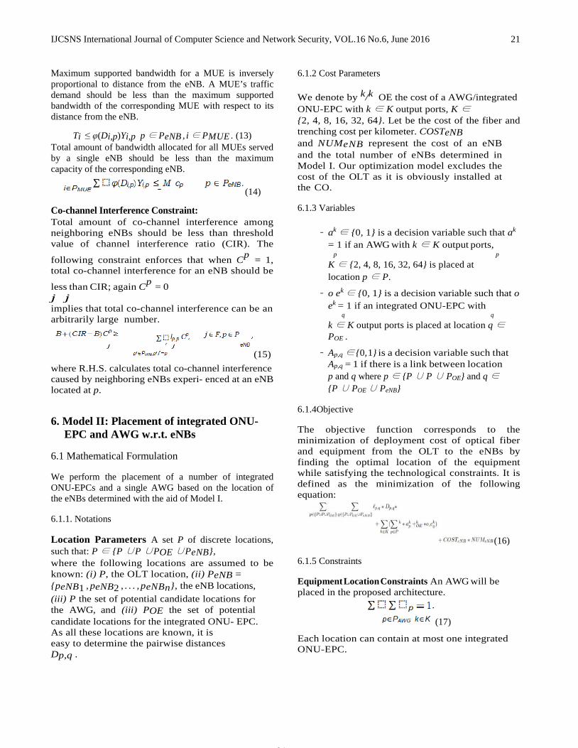
Figure 7: Cost of Equipment
Table 1 contains the values taken for the cost of the AWG [29] and the integrated ONU-
EPC(arbitrarily assumed). For the costs related to optical fiber cables, we use the value of 7160$/km [29], assuming it includes the cost of trenching and laying the optical fiber cables. We have also assumed the installation cost of each eNB as $20,000. We randomly generate 60, 16 and 8 candidate locations for the placement of the eNB, the integrated ONU-EPC and the AWG respectively, as seen in Figure 7.
Table 1: Cost of Equipment # output
ports Integrated ONU-EPC
cost ($) AWG cost ($)
2 1,000 950 4 2,000 1,100 8 4,000 1,400
16 6,000 2,000 32 8,000 3,200 64 10,700 5,600
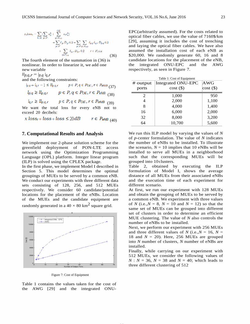
We run this ILP model by varying the values of N of p-center formulation. The value of N indicates the number of eNBs to be installed. To illustrate the scenario, N = 10 implies that 10 eNBs will be installed to serve all MUEs in a neighborhood such that the corresponding MUEs will be grouped into 10 clusters. Table 2, obtained by executing the ILP formulation of Model I, shows the average distance of all MUEs from their associated eNBs and the execution time of each experiment for different scenario. At first, we run our experiment with 128 MUEs and obtain the grouping of MUEs to be served by a common eNB. We experiment with three values of N (i.e.,N = 8, N = 10 and N = 12) so that the same set of MUEs can be grouped into different set of clusters in order to determine an efficient MUE clustering. The value of N also controls the number of eNBs to be installed. Next, we perform our experiment with 256 MUEs and three different values of N (i.e.,N = 16, N = 18 and N = 20). Here, 256 MUEs are grouped into N number of clusters, N number of eNBs are installed. Finally, while carrying on our experiment with 512 MUEs, we consider the following values of N : N = 36, N = 38 and N = 40; which leads to three different clustering of 512
IJCSNS International Journal of Computer Science and Network Security, VOL.16 No.6, June 2016 24
Figure 8: Computational Results on Model I
MUEs. We observe that execution time increases significantly when we run our experiments with smaller values of N , as seen in Figure 8.
Table 2: Computational Results on Model I
In the second phase, we implement Model II described in Section 6. This model deter- mines the optimal placement of a number of integrated ONU-EPCs as well as a single AWG based on the location of the eNBs determined during the first phase. In this phase, first, we carry on our experiment with different number of eNBs (i.e., 8,10,12) whose locations are determined by simulating Model I using 128 MUEs. Next, we extend our experiment with two different set of eNBs. The first set contains 16,18, and 20 eNBs obtained by grouping 256 MUEs. The second set consists of 36, 38, and 40 eNBs which is achieved by associating 512 MUEs with different number of eNBs. After executing the two phases of our proposed optimization scheme, an efficient physical architecture/topology of a hybrid PON-LTE ac- cess network is built in which the OLT is the root of the tree and the MUEs are the leaves. The AWG, integrated ONU-EPC, and the eNBs are positioned in between the OLT and the MUEs. Table 3, obtained by simulating the ILP formulation of Model II, shows a comparison of approximate deployment cost with respect to different scenario
of a PON-LTE access network. For all scenarios, we observe that increasing the value of N , obviously increases the deployment cost of the PON-LTE access network. Again, increased number of installed eNBs reduces the distance of each MUE from its associated eNB which results in higher available bandwidth and stronger received signal for the corresponding MUE. As a result, the average distance parameter of Table 2 can serve as an indicator for specifying overall quality of service (QoS) of the LTE network. While designing an efficient PON-LTE access network, we need to tradeoff between the deployment cost and the overall QoS.
Table 3: Deployment Cost for Different Scenarios
8. Conclusion
We investigated a number of optical-wireless access network architectures and described the possible optimization process for finding suitable location of all equipment of the corresponding network. Finally, we proposed a novel PON-LTE access network architecture and a 2-phase optimization scheme which can determine the placement of equipment in such a hybrid network. First phase of our proposed scheme includes an ILP model which optimizes the greenfield deployment of LTE network based on the static distribution of mobile user equipment (MUEs). The proposed model determines the optimal clustering of MUEs and location of eNBs in a neighborhood. Second phase of our scheme consists in another ILP model which optimally determines the location of a number of integrated ONU-EPCs as well as a single AWG while building an efficient hybrid PON-LTE access network topology. It is the most comprehensive model, proposed so far, for the optimal placement of equipment in a hybrid optical-wireless network taking into account various physical layer constraints of both PON and LTE network.

25
IJCSNS International Journal of Computer Science and Network Security, VOL.16 No.6, June 2016
25
References [1] T. Koonen, Fiber to the home/fiber to the premises: What,
where, and when?, in: Proceedings of the IEEE, Vol. 94, 2006, pp. 911–934.
[2] P. Urban, G. Vall-llosera, E. Medeiros, S. Dahlfort, Fiber plant manager: an OTDR-and OTM-based PON monitoring system, IEEE Communications Magazine 51 (2) (2013) S9–S15.
[3] M. Mahloo, C. M. Machucab, J. Chena, L. Wosinskaa, Protection cost evaluation of WDM-based next generation optical access networks, Optical Switching and Networking 10 (1) (2013) 89–99.
[4] R. Roka, The Designing of NG-PON Networks Using the HPON Network Configuration, Journal of Communication and Computer 9 (2012) 669–678.
[5] A. R. Prasad, N. R.Prasad, 802.11 WLANs and IP Networking: Security, QoS, and mobility, Artech House, U.S.A., 2005.
[6] ISO/IEC 8802-11, ANSI/IEEE Std 802.11, First Edition 1999-00-00,Information Technology- Telecommunications and information exchange between systems - Local and metropolitan area networks - Specific requirements - Part 11:Wireless LAN Medium Access Control(MAC) and Physical Layer (PHY) specification.
[7] J. Li, G. Shen, Cost Minimization Planning for Greenfield Passive Optical Networks, Journal of Optical Communications and Networking 1 (1) (2009) 17–29.
[8] M. Hajduczenia, B. Lakic, H. da Silva, P. Monteiro, Optimized passive optical network deployment, Journal of Optical Networking 6 (9) (2007) 1079–1104.
[9] A.Mitcsenkov, G. Paksy, T. Cinkler, Topology Design and Capex Estimation for Passive Optical Networks, in: 6th International ICST Conference on Broadband Communica- tions, Networks, and Systems (BROADNETS), 2009, pp. 1–10.
[10] A. Mitcsenkov, G. Paksy, T. Cinkler, Geography- and infrastructure-aware topology design methodology for broadband access networks (FTTx), Photonic Network Com- munications 21 (3) (2011) 253–266.
[11] J. Zhang, N. Ansari, Minimizing the Arrayed Waveguide Grating Cost and the Optical Cable Cost in Deploying WDM Passive Optical Networks, Journal of Optical Commu- nications and Networking (2009) 352–365.
[12] B. Jaumard, R. Chowdhury, Location and Allocation of Switching Equipment (Split- ters/AWGs) in a WDM PON Network, in: 20th International Conference on Computer Communication Networks (ICCCN), 2011, pp. 1–8.
[13] B. Jaumard, R. Chowdhury, Selection and placement of switching equipment in a Broad- band Access Network, in: International Conference on Computing, Networking and Communications (ICNC), 2012, pp. 297–303.
[14] R. Chowdhury, B. Jaumard, A Cross Layer Optimization Scheme for WDM PON Net- work Design and Dimensioning, in: IEEE International Conference on Communications (IEEE ICC), 2012, pp. 3149–3154.
[15] A. Shami, X. Bai, C. Assi, N. Ghani, Jitter performance in Ethernet passive optical networks, Journal of Lightwave Technology 23 (4) (2005) 1745–1753.
[16] R. Chowdhury, A. Shami, K. Almustafa, Designing of next-generation hybrid optical- wireless access network, 14th
International Conference on Innovations for Community Services (I4CS), 2014 (2014) 9–15.
[17] S. Sarkar, B. Mukherjee, S. Dixit, Optimum placement of multiple optical network units (ONUs) in optical-wireless hybrid access networks, in: Optical Fiber Communication Conference (OFC), 2006.
[18] S. Sarkar, B. Mukherjee, S. Dixit, Towards global optimization of multiple ONUs place- ment in hybrid optical-wireless broadband access networks, in: The 5th International Conference on Optical Internet (COIN), 2006, pp. 65–67.
[19] S. Sarkar, H.-H. Yen, S. Dixit, B. Mukherjee, A mixed integer programming model for optimum placement of base stations and optical network units in a hybrid wireless- optical broadband access network (WOBAN), in: Wireless Communications and Net- working Conference(WCNC), 2007, pp. 3910–3914.
[20] S. Sarkar, H.-H. Yen, S. Dixit, B. Mukherjee, DARA: Delay-aware routing algorithm in a hybrid wireless-optical broadband access network (WOBAN), in: Proceedings of The IEEE International Conference on Communications (ICC), Glasgow, U.K., 2007, pp. 2480–2484.
[21] S. Sarkar, H.-H. Yen, S. Dixit, B. Mukherjee, A novel delay-aware routing algorithm (DARA) for a hybrid wireless-optical broadband access network (WOBAN), IEEE Net- work Magazine 22 (3) (2008) 20–28.
[22] S. Sarkar, S. Dixit, B. Mukherjee, Hybrid wireless-optical broadband-access network (WOBAN): A review of relevant challenges, Journal of Lightwave Technology 25 (11) (2007) 3329–3340.
[23] S. Sarkar, H.-H. Yen, S. Dixit, B. Mukherjee, Hybrid wireless-optical broadband access network (WOBAN): network planning and setup, IEEE Journal on Selected Areas in Communications 26 (6) (2008) 12–21.
[24] B. Lin, J. Tapolcai, P.-H. Ho, Dimensioning and Site Planning of Integrated PON and Wireless Cooperative Networks for Fixed Mobile Convergence, IEEE Transactions on Vehicular Technology 60 (9) (2011) 4528–4538.
[25] M. Mirahmadi, A. Shami, Traffic-prediction-assisted dynamic bandwidth assignment for hybrid optical wireless networks, Computer Networks 56 (1) (2012) 244–259.
[26] A. Ahmed, A. Shami, RPR-EPON-WiMAX Hybrid Network: A Solution for Access and Metro Networks, Journal of Optical Communications and Networking 4 (3) (2012) 173–188.
[27] S. H. Owen, M. S. Daskin, Strategic facility location: A review, European Journal of Operational Research 111 (3) (1998) 423 – 447.
[28] A. Suzuki, Z. Drezner, The p-center Location Problem in an Area, Location Science 4 (1/2) (1996) 69–82.
[29] J. Chen, L. Wosinska, C. Machuca, M. Jaeger, Cost vs. reliability performance study of fiber access network architectures, IEEE Communications Magazine 48 (2) (2010) 56–65.
[30] M. Kalil, A. Shami, and A. Al-Dweik, QoS-Aware Power-E_cient Scheduler for LTE Uplink, IEEE Transactions on Mobile Computing, vol.14, no.8, pp.1672-1685, Aug. 2015
[31] M. Mirahmadi, A. Al-Dweik, and A. Shami, "Interference Modeling and Performance Evaluation of Heterogeneous

IJCSNS International Journal of Computer Science and Network Security, VOL.16 No.6, June 2016 26
Cellular Networks," IEEE Transactions on Communications, vol.62, no.6, pp.2132-2144, June 2014.
[32] D. Dechene and A. Shami, Energy-Aware Resource Allocation Strategies for LTE Up-link with Synchronous HARQ Constraints," IEEE Transactions on Mobile Computing,Volume 13, no. 2, pp. 422-433, February 2014.
[33] M. Mirahmadi, A. Al-Dweik, and A. Shami, BER Reduction of OFDM Based Broad-band Communication Systems over Multipath Channels with Impulsive Noise," IEEE Transactions on Communications, Volume 61, issue 11, pp. 4602-4615, November 2013.
[34] X. Bai, A. Shami, and Y. Ye, "Robust QoS Control for Single Carrier PMP Mode IEEE 802.16 System," IEEE Transactions on Mobile Computing, vol. 7, no. 4, pp. 416-429, Apr. 2008.
[35] X. Bai, A. Shami, and C. Assi, On the Fairness of Dynamic Bandwidth Allocation Schemes in EPON Networks, Elsevier Comp. Communications, Vol. 29, pp. 2123-2135, July 2006.
[36] A. Shami, Xiaofeng Bai, N. Ghani, C. Assi and H. T. Mouftah, "QoS Control Schemes for Two-Stage Ethernet Passive Optical Access Networks, IEEE Journal on Selected Areas in Communications (IEEE JSAC), Vol. 28, pp. 1467-1478, August 2005.
[37] X. Bai, A. Shami, and C. Assi, On the Fairness of Dynamic Bandwidth Allocation Schemes in EPON Networks, Elsevier Comp. Communications, Vol. 29, pp. 2123-2135, July 2006.
Dr. Rejaul Chowdhury received Ph.D. in Computer Science from Concordia University, Montreal, Canada. Later on, he worked as a Post-doctoral Fellow at the Department of Electrical & Computer Engineering of Western University, London, Canada. His research focuses on mathematical modeling and algorithm design for large scale optimization problems arising in optical access networks (e.g. TDM/WDM PON), wireless access networks (e.g. WiMAX, Wi-Fi, LTE), hybrid optical wireless access networks (e.g. PON-WiMAX, PON-WiFi, PON-WiMAX- WiFi, PON-LTE) as well as in Cloud network. Currently, Dr. Chowdhury is working as an IT Analyst of Canada Revenue agency. He is also teaching Part-time in the Information and Communications Technology (ICT) Department of Algonquin College in Ottawa.
Khaled Almustafa received his B.E.Sc. in Electrical Engineering, M.E.Sc. and Ph.D. in Wireless Communication from the University of Western Ontario (UWO), London, Ontario, Canada in 2003, 2004 and 2007 respectively. He is currently the Vice Dean for the College of Engineering at Prince Sultan University (PSU), Riyadh, K.S.A. he also served as the Chairman of
the Department of Communication and Networks Engineering, College of Engineering at Prince Sultan University PSU), Riyadh, K.S.A. (2010-2015). His research interests include MIMO systems, Channel Security and Access Networks.