Design of novel adaptive magnetic adhesion mechanism for …etheses.whiterose.ac.uk/16903/1/Thesis...
157
Design of novel adaptive magnetic adhesion mechanism for climbing robots in ferric structures By: Francisco Ochoa Cardenas A thesis submitted in partial fulfilment of the requirements for the degree of Doctor of Philosophy The University of Sheffield Faculty of Engendering Department of Automatic Control and Systems Engineering November 2016
-
Upload
truongkhue -
Category
Documents
-
view
215 -
download
0
Transcript of Design of novel adaptive magnetic adhesion mechanism for …etheses.whiterose.ac.uk/16903/1/Thesis...
Design of novel adaptive magnetic adhesion mechanism for climbing robots in ferric structures
By:
Francisco Ochoa Cardenas A thesis submitted in partial fulfilment of the requirements for the degree of
Doctor of Philosophy
The University of Sheffield Faculty of Engendering
Department of Automatic Control and Systems Engineering
November 2016

ii

iii

iv

iii
Abstract
The work presented in this thesis proposes a novel adaptive magnetic
adhesion mechanism that can be implemented in most locomotion
mechanisms employed in climbing robots for ferric structures. This novel
mechanism has the capability to switch OFF and ON its magnetic adhesion
with minimal power consumption, and remain at either state after the
excitation is removed. Furthermore, the proposed adhesion mechanism has
the ability to adapt the strength of the adhesive force to a desired magnitude.
These capabilities make the proposed adhesion mechanism a potential
solution in the field of wall climbing robots.
The novel contributions of the proposed mechanism include the
switching of the adhesive force, selectivity of the adhesive force magnitude;
determination of the parameters that have an impact in the final adhesive
force. Finally, a final prototype is constructed with customised components
and it is subject to a set of simulations and experiments to validate its
performance.

iv
v
Acknowledgments
Firstly, I would like to express my deepest gratitude to my supervisor,
Prof. Tony J. Dodd, for all his support, guidance through the PhD and
specially for his patience.
All my gratitude to the people that encouraged me on pursuing the PhD
and that always were present.
• My wife, whose support, patience and encouragement where vital for
reaching the end.
• My daughter and son, which are the motor that push me go further and
never give up.
• My parents, whose care, support and guidance in life have driven me to
reach the unimaginable.
• My aunts Cuca and Pina Ochoa, and uncle Luis Ochoa, who set the
basis, along with my parents, that allowed me be where I am, and more
important to be who I am
Last but not least, I would like to thank my two Mexicans sponsors,
CONACyT and SEP (under Becas Complemento SEP grant), for the great
opportunity to going abroad to study and contribute the future of my
country.

vi

vii
Contents
1.1. Motivation ........................................................................................................ 2
1.2. Problem definition ......................................................................................... 4
1.3. Aims and objectives ....................................................................................... 4
1.4. Contributions ...................................................................................................5
1.5. Thesis outline .................................................................................................. 6
2.1. Classification of the unmanned vehicles ................................................ 10
2.2. Wall climbing mobile robots ...................................................................... 14
2.2.1. Locomotion mechanisms ............................................................... 18
2.2.2. Adhesion mechanisms .................................................................... 21
2.3. WCMR for inspection of ferric structures ............................................. 26
2.3.1. Electro-permanent magnets ......................................................... 28
2.4. Concluding remarks ..................................................................................... 31
3.1. Theory.............................................................................................................. 33

viii
3.1.1. Important concepts ........................................................................ 34
3.2. Working principles ...................................................................................... 39
3.2.1. OFF and ON configurations .......................................................... 40
3.2.2. Variable magnetic adhesive force ............................................... 43
3.2.3. Characteristics of the EPMs ......................................................... 44
3.3. Validation of the electro-permanent magnet concept ....................... 45
3.3.1. Basic configuration and components of the EPM .................. 46
3.3.2. Equipment and experimental setup .......................................... 48
3.3.3. Simulation and experimental results: basic OFF and ON configurations ........................................................................... 54
3.3.4. Switching between states and variable magnetic adhesive force ................................................................................... 58
3.4. Concluding remarks .................................................................................... 64
4.1. Locomotion mechanism selection .......................................................... 66
4.1.1. Selection of the locomotion mechanism and EPMAM integration ......................................................................................... 70
4.2. EPMAM Implementation in the wheeled locomotion mechanism ..................................................................................................... 73
4.2.1. Preliminary simulations of the wheeled EPMAM design ...................................................................................................77
4.3. Validation of the proposed wheeled locomotion mechanism with EPMAM .................................................................................................. 80
4.3.1. OFF and ON states validation ....................................................... 81
4.3.2. Validation of the OFF-ON and ON-OFF switching, and variable magnetic adhesion .......................................................... 83
4.4. Concluding remarks .................................................................................... 90
5.1. Influence of the individual design components in the final adhesive force ................................................................................................ 94
5.1.1. Steel keepers ..................................................................................... 95
5.1.2. Enamelled wire gauge..................................................................... 97
5.1.3. Gap between EPM device and adhesion surface ..................... 98
5.2. Configuration of the EPMAM into the wheel ...................................... 101
5.2.1. Rotating EPMAM ............................................................................ 101
ix
5.2.2. Static EPMAM ................................................................................. 102
5.3. Customised EPMAM design for manufacturing purposes .............. 104
5.3.1. Manufacturability of the EPMAM components .................... 104
5.4. Simulation and experimental results from the customised EPMAM ........................................................................................................... 107
5.4.1. Discussion ........................................................................................ 112
5.5. EPMAM Integration into a Functional Wheel Design ...................... 112
5.5.1. Wheel design with an internal fixed EPMAM ........................ 113
5.5.2. Discussion ........................................................................................ 116
5.6. Concluding remarks ................................................................................... 117
6.1. Future work .................................................................................................. 121

x

xi
List of Figures

xii
xiii

xiv

xv
List of Tables

xvi
xvii
Nomenclature
A Cross sectional area
B Magnetic flux density
F Magnetomotive force
H Magnetic field intensity
Hc Coercivity / Intensity of the magnetic field (Oe)
I Current flowing through the coil
i(t) Electric current
L Inductance
N Number of turns in a coil
Oe Oersted
R Resistance
S/s Samples per second / Sampling rate
t Time
V Voltage
𝓁 Length of the coil
τ Time constant
ρ Resistivity of a given material

xviii
xix
List of Acronyms
Alnico Aluminium-Nickel-Cobalt
AWS American Wire Gauge
EM Electro Magnet
emf Electromotive force
EPM Electro-Permanent Magnet
EPMAM Electro-Permanent Magnet Adhesion Mechanism
FEA Finite Element Analysis
L-T H Legs-Tracks Hybrid
L-W H Legs-Wheels Hybrid
L-W-T H Legs-Tracks-Wheels Hybrid
M/EMAM Magnetic/Electro-Magnetic Adhesion Mechanism
MFVF Magnetic Field Viewing Film
MR Mobile Robots
NdFeB Neodymium-Iron-Boron
PM Permanent Magnet
SWG Standard Wire Gauge
T-W H Tracks-Wheels Hybrid
UAVs Unmanned Aerial Vehicles
UGVs Unmanned Ground Vehicles
USVs Unmanned Surface Vehicles
UUVs Unmanned Undersea Vehicles
UV Unmanned Vehicle
WCMR Wall Climbing Mobile Robot


1
Chapter 1
Introduction
Since the beginning of modern civilization, humans have pursued the
development of new technologies which can allow them to simplify work and
increase productivity, among other objectives. These new technologies are
intended to carry out repetitive, heavy, dull or dangerous tasks, where
humans are at risk or cannot be involved.
As a result of the industrial revolution, new technologies were
developed in fields like metallurgy, steam power, textile manufacturing and
machine tools, among many others. Although these breakthrough
technologies have increased productivity and reduced physical work for
humans, they have also augmented the complexity of machineries, and all
related components and structures that make them operational. As a result
of this progress, lots of infrastructure were developed and constructed, such
as manufacturing and storage buildings, bridges and railways for
transportation of goods. Since then, the complexity and quantity of these
structures has increased exponentially.
The majority of the infrastructure developed from the late 19th century
until these days has been made from steel. These often require constant
maintenance and inspection in order to remain functional. Up to now most
of these maintenance and inspection tasks were performed by humans,

Chapter 1. Introduction
2
which in many cases is risky and life threatening for humans, and requires
lots of resources.
To deal with this situation, some of these fixed-base systems started
migrating to mobile systems. This provides more flexibility to deal with the
tremendous growth of new technologies, and in order to keep structures and
equipment in working conditions, with minimum risk for the users.
In the last couple of decades, inspection, maintenance and surveillance
tasks have become very challenging, risky and high cost. Some of the main
reasons for this are: the exponential growth in the number of structures that
are being built, the increasing complexity of these structures (either for
aesthetic or efficiency reasons), the scenario surrounding the structures
(dangerous, dull, etc.), among others.
1.1. Motivation
These circumstances have opened up new fields of opportunity to
satisfy the increasing need of more efficient, less expensive and faster
inspection procedures. One particular new technique to address this is the
employment of Unmanned Vehicles (UV) or Mobile Robots (MR) for
inspection, maintenance and surveillance tasks. Most of the MRs developed
up to now have being designed for a particular task, or to be employed in a
specific scenario. Although these MRs are highly valued by military and
commercial entities, the need of a multi-task MR has been increasingly
pursued in the last decade. Unfortunately, up to now, there is still no MR
that can satisfy this specific need (multitasking). The Unmanned Ground
Vehicles (UGVs) are the likely to be the closest to reach multitasking
capabilities.
A particular, and very important case, is the development of a multi-
task UGV for inspection of vertical and complex structures such as, bridges,
industrial plants, and building frames. This particular type of UGVs are
commonly referred to as, wall climbing UGVs. More recently, some
researchers are referring to UGVs capable to move on, and climb vertical

Chapter 1. Introduction
3
structures as “Scansorial mobile robots”. This last term, is taken from
zoology, and refers to any creature capable or adapted for climbing.
Most of these scansorial UGVs have been designed for a specific task
and scenario. This is mainly because of the limitations of locomotion and
adhesion mechanisms available for the case of climbing structures.
The main motivation for the present research is the development of a
novel adhesion mechanism, which can be integrated into most of the
locomotion mechanisms used by MRs for inspection in ferric structures.
This adhesion mechanism must ensure manoeuvrability in complex
structures, and enhance the MR capability to overcome different types of
obstacles.
In recent years, the development of these MRs has been fostered by the
exponential growth and innovation of new technologies such as high-
speed/low-cost computing, high-bandwidth and reliable wireless
communications (Fish & Sitzman 2009).
The development of most of these Mobile Robots (MR) was inspired by
the military (US DoD 2013; Defense 1992; Carroll et al. 2004; Clapper et al.
2009), which normally invests in these technologies to cover areas such as
surveillance missions. This development is followed by a commercial use,
which is normally carried out by big companies.
These unmanned MRs can be grouped in three main domains: Air
Domain - Unmanned Air Vehicles (UAVs); Maritime Domain - Unmanned
Surface Vehicles (USVs) and Unmanned Undersea Vehicles (UUVs); and
Ground Domain - Unmanned Ground Vehicles (UGVs). These three domains
will be covered in more detail through the literature review, Section 2.1.
Although the new technologies in the construction and structural
fields are moving more towards increased use of composites, up to now most
of the structures are still built using steel or ferrite materials. These
structures are expected to remain in use for at least a few more decades. That
is the reason for developing systems or vehicles for inspection all these
structures, with tasks such as: looking at corrosion, fatigue, damages, among

Chapter 1. Introduction
4
others, that could put at risk the safety of these structures. The focus of the
present research is to employ electromagnetic technology, as the adhesion
mechanism, for the specific case of ferric structures.
1.2. Problem definition
The research proposal for the present PhD is the design and
development of a scansorial Mobile Robot (MR) for inspection of ferric
structures. Two key components of the MR will be the main focus. First of
all, to develop a novel active adhesion mechanism for ferromagnetic surfaces
by means of a new “Electro-Permanent Magnet” (EPM) technology. This novel
technology will enhance the adhesion system, with an active mechanism for
attaching, detaching or adjusting the adhesion force, depending to the
conditions. This new approach for the magnetic adhesion mechanism, which
is being explored for this particular case, is a combination of two Permanent
Magnets (PM) with different properties (magnetically hard and semi-hard)
coiled together with a magnetic wire. In fact, it can be referred as an Electro-
Magnet (EM) with a core formed from two PMs.
1.3. Aims and objectives
The aim of this research is to develop a novel active magnetic adhesion
mechanism capable of switching OFF and ON, and varying the strength of its
magnetic adhesive force. This novel adhesion mechanism has to be suitable
for being integrated into most of the locomotion mechanism used in MR for
inspection of ferric structures
The objectives of the research are:
1. Design and development of a novel magnetic adhesion mechanism, by
the use of Electro-Permanent Magnets (EPMs), which can be
implemented in different locomotion systems e.g. legged, tracked or
wheeled.

Chapter 1. Introduction
5
2. Simulation and validation of the novel adhesion mechanism, to
determine the influence of the parameters on the performance of the
adhesion mechanism, such as: voltage, number of turns in the windings,
gage of the enamelled wire.
3. Optimization of the critical components and their influence in the
performance of the adhesion mechanism.
4. Testing and characterization of the novel adhesion mechanism, to
determine the curve for the force versus electrical pulse magnitude.
1.4. Contributions
The contributions of the proposed research are:
1. Novel active adhesion mechanism: Designed using EPM technology. This
active adhesion mechanism has the advantage of being active, allowing
the regulation of the magnetic adhesion force required in a particular
situation.
2. Determination of the parameters that have an impact in the performance
of the adhesion mechanism in order to perform an optimization of the
mechanism.
3. Testing a wheel that integrates the EPM adhesion mechanism, to be
implemented in a MR.
Publications
The work performed in this thesis has contributed the following
publications:
• F. Ochoa-Cardenas and T. J. Dodd, "Design of an active magnetic wheel
with a varying Electro-Permanent Magnet adhesion mechanism,"
Intelligent Robots and Systems (IROS), 2015 IEEE/RSJ International
Conference on, Hamburg, 2015, pp. 3340-3345. doi:
10.1109/IROS.2015.7353842
Chapter 1. Introduction
6
• F. Ochoa-Cardenas and T. J. Dodd, "Design of a Continuously Varying
Electro-Permanent Magnet Adhesion Mechanism," Towards
Autonomous Robotic Systems (TAROS 2015), 16th Annual Conference,
Liverpool, UK, 2015, Proceedings, pp. 192-197. doi: 10.1007/978-3-319-
22416-9.
1.5. Thesis outline
The structure of the thesis is set to provide a literature review and
theoretical background in Chapters 2 and 3, the main research derived from
the theory is presented in Chapters 4 and 5. Finally, the concluding remarks
and future work are presented in Chapter 6. A more detailed description of
each chapter is presented next:
• Chapter 2 presents the state-of-the-art of MR used for inspection tasks.
These MR are classified by their domain, and the most suitable domain
for a MR for inspection of vertical ferric structures is selected. From
the selected domain, wall climbing robots chosen as the best option.
Furthermore, the different locomotion and adhesion mechanisms used
in climbing robots are presented and a novel adhesion mechanism
using Electro-Permanent Magnets (EPM) is proposed.
• Chapter 3 presents the theoretical background for EPM and their
working principles are explored. Based in the presented theory, an
EPM device is constructed using off-the-shelf components and the EPM
concept is validated by Finite Element Analysis (FEA) simulations and
the corresponding experiments, on the EPM device.
• Chapter 4 presents the possible configurations for integrating the EPM
concept as the main adhesion mechanism for a previously selected
locomotion mechanism. A new EPM device is constructed and the
corresponding FEA simulations and experiments are performed in
order to validate the feasibility of the proposed EPM-Locomotion
mechanism integration.

Chapter 1. Introduction
7
• Chapter 5 presents an EPM wheel design using customised components
and detailed analysis of the influence of each component on the final
adhesive force is performed. From the outcomes from the analysis a
final EPM adhesion mechanism is designed and manufactured. A set of
FEA simulations and experiments to validate the design. Finally a
functional EPM wheel is built using 3D printed components for the
assembly.
• Chapter 6 summarises the content of the thesis and presents the
concluding remarks. Finally, different ideas are presented for a
possible future work.
Chapter 1. Introduction
8
9
Chapter 2
Literature Review
As mentioned in Chapter 1, there exists an increasing need for systems
that help humans carry out inspection, maintenance and surveillance tasks
for existing infrastructure. Over the years these tasks have been performed
by humans, which in some cases can be dangerous for personnel involved.
Furthermore, the cost of the safety systems and equipment required to
guarantee the protection of the personnel, increases dramatically with the
size, complexity and age of the structure inspected. The time and cost to
mount the infrastructure needed to perform the inspection or maintenance
task is another factor that impacts considerably. For these reasons the
development of MRs, which help to reduce the amount of resources and
personnel involved in these tasks, is becoming an important field of
research.
Steel structures are an essential part of modern life. From mere
aesthetic design or as a touristic landmark, such as the Eiffel tower, to vital
infrastructure like bridges, manufacturing plants, storage vessels, and
structural frames, among others. Whether they are new, or have been erected
decades ago, these structures require a continuous inspection and
maintenance in order to remain functional. The execution of these
inspection and maintenance activities comprise dangerous, dull or dirty
tasks, which in some situations are unsafe for humans to perform.

Chapter 2. Literature Review
10
The employment of MR is becoming more and more common in the
field of inspection and maintenance of steel structures. This is greatly thanks
to the recent development of new technologies in different fields, which are
being applied as adhesion mechanisms for the MRs.
The present chapter presents the current state-of-the-art on the
development of MRs for close inspection tasks, in complex structures and
unstructured environments, with a particular emphasis on the technologies
used in MR employed in ferric structures. In Section 2.1 an introduction of
the evolution of inspection robots is presented and the MRs are categorized
into the three main areas according to their main environmental domain.
The most suitable category for an MR for close inspection of large, complex
structures, is selected. The specific group of climbing robots is then explored
in Section 2.2, and the two main mechanisms (locomotion and adhesion) that
allow them to climb structures are presented. Next, in Section 2.3, the state-
of-the-art of Wall Climbing Mobile Robot (WCMR) used for inspection of
ferric structures is explored. Finally, the concluding remarks are presented
in Section 2.4
2.1. Classification of the unmanned vehicles
In today’s society, there exists an increasing need for systems for
monitoring, cleaning, maintenance, and surveillance tasks of existing old
and new infrastructure such as: power plants, bridges, platforms or self-
standing structures (Kolhalkar & Patil 2012). Most of these tasks are
performed by humans, which results in risky, high cost, dull activities, and
the need of lots of resources.
One way to minimize the negative impacts of these tasks is the
employment of MRs (Perhinschi et al. 2010; Clapper et al. 2009; Defense 1992).
These inspection and maintenance tasks, among others such as providing
aid in public safety or military activities, are the main incentives leading the
design and development of these type of MRs.

Chapter 2. Literature Review
11
By definition any vehicle without humans on-board is considered an
MR. They can be:
• Remotely operated, fully controlled by an operator.
• Semi-autonomous, with remote assistance of an operator for specific
tasks or manoeuvres.
• Autonomous, capable of navigating on their own, and decision making,
to some extent.
The last couple of decades have seen a significant progress in areas
such as computational power, communications, vision systems, navigation,
systems miniaturisation, and energy storage (Bruch et al. 2005). All these
advancements have allowed the development of new technologies, which
have led to the design of MRs and boosted their implementation in all kind
of scenarios (De Sousa & Andrade Gonçalves 2011).
MRs are categorised according to the environmental domain where
they are being employed:
• Aerial domain for Unmanned Aerial Vehicles (UAVs).
• Maritime domain (aquatic) which is subdivided into two
classifications: Unmanned Underwater Vehicles (UUVs) and
Unmanned Surface Vehicles (USVs).
• Ground domain (terrestrial) for Unmanned Ground Vehicles (UGVs)
that contains all on-ground locomotion systems for flat, rough and
inclined environments.
All MR, employed for inspection or maintenance tasks, have
constraints that are inherent to the domain to which they belong, these can
enhance or limit their implementation depending on the circumstances.
These constraints, for each domain (aerial, maritime and ground), are
presented next and the most suitable type of MR is selected for the case of
close inspection of large, complex structures.

Chapter 2. Literature Review
12
Aerial domain
In the aerial domain case, UAVs are mainly used when an inspection
outside the structure is needed. These systems have experienced a great
growth in recent years (Clapper et al. 2009), pushed by the military seeking
new ways to enhance surveillance tasks and to assist troops in combat
operations (Khurshid & Bing-rong 2004; Defense 1992; US DoD 2013). In the
case of non-military use, UAVs are implemented in applications, such as:
rescue and surveillance tasks (Burri et al. 2012); building and structure
inspection (Winkvist et al. 2013); or power transmission lines inspections
(Smith 2001; Hrabar et al. 2010), (Wang et al. 2010).
This type of UAVs present a major limitation, they are not suitable for
close and detailed inspection of complex structures such as bridges,
industrial plants or inside structures. These limitation is essentially due to
the turbulence that their propulsion mechanism generates. When the UAV
is in an open space, with no close obstacles, turbulence is not a problem. But
being surrounded by a huge diversity of existing obstacles, mainly inside the
structures, becomes a major problem. This results in the impossibility of
getting close enough for a detailed inspection of the targets. Although these
issues have been addressed in recent years (Gunetti et al. 2011; Winkvist et
al. 2013), key challenges remain before they are reliable and trustable for
commercial use. Hence, UAV’s are not a practical solution to be implemented
in the field of close inspection and maintenance, up to now.
Maritime domain
In the case of the maritime domain, USV are limited to a 2D spatial
domain. They are suitable for approaching structures that are in their
domain but are impeded to get into the structure for a detailed examination.
On the other hand, UUV move in a 3D spatial domain, which extends their
operation range compared to USV. However, this type of MRs exhibit issues
similar to those on the aerial domain (AUVIS 2013; Manley 2008).
Specifically, for UUV an analogy can be made to a UAV, in the way they

Chapter 2. Literature Review
13
approach structures or targets. Their spatial domain is essentially the same
(three-dimensional domain), changing only the medium from air to water.
UUVs and USVs have been developed mainly for military purposes
(Agoros 1994; Gogarty & Robinson 2011; US DoD 2013). Additionally, the
scientific need for the exploration of the vast immensity of the deep seas
(Hobson et al. 2001; Pascoal et al. 2000), along with offshore industry, like oil
or deep sea-mining companies (Damus et al. 2002; AUVIS 2013), or the growth
of optical communications, that connect continents (Bannon 2000; Santos
et al. 2013) have pushed the development of these types of vehicles (Manley
2008). However, these MR are only capable of inspecting the outside of
structures, having difficulties to go inside them for a closer approach. In
addition to a lesser quantity of structures that exist underwater, compared
to those on ground, the use UUV and USV for the case of the present work is
excluded.
Ground domain
Now, for the case of the ground domain, the development of UGVs has
a similar history to UAVs, UUVs and USVs. They were first developed for
military purposes (Haas et al. 1997; Defense 1992; Carroll et al. 2004), but
quickly, scientific, commercial and civilian uses were established. This
category of MRs is the most researched and has the widest range of
applications, as well as, shapes and locomotion mechanisms (Caprari &
Breitenmoser 2012; Okamoto et al. 2012; Kim et al. 2010; Haraguchi et al. 2005;
Granosik et al. 2005; Byrd & DeVries 1990; Asano et al. 1983).
UGVs, compared to UAVs or UUVs, have the ability to move through
the area of interest, approaching structures closer and maintaining a fixed
position with minimal power consumption. Furthermore, they can navigate
inside and through the constructions, in an unstructured, confined scenario
(Caprari & Breitenmoser 2012).
Most of the UGVs are conceived for solving a specific problem or
performing a particular task, such as, maintenance, inspection, surveillance,

Chapter 2. Literature Review
14
or safety tasks. Examples of these include: power plants and nuclear facilities
(Zwicker et al. 2010; Guo et al. 2010; Fulbright & Stephens 1995; Roman 1991;
Byrd & DeVries 1990), power transmission lines and bridges (Katrašnik et al.
2010; Debenest et al. 2008; Cho et al. 2013; Yun et al. 2013; Liu et al. 2008;
Wang et al. 2010), pipes and sewage (Yoon & Park 2012; Kwon et al. 2010;
Tavakoli et al. 2010; Lee et al. 2012) or vertical structures (Kalra et al. 2006;
Kalra & Gu 2007; Fernández et al. 2010; Yoshida & Ma 2010; Schoeneich et al.
2011; Menon et al. 2004). Hence, the need of a UGV capable of travelling
around most of the existing structures, and especially able to climb the
structure to reach areas inaccessible for humans, or that requires huge
amounts of time and resources to approach, was observed.
Through next section WCMRs are discussed in more detail, dividing
them by their type of locomotion and adhesion mechanism.
2.2. Wall climbing mobile robots
A particular challenging area for inspection UGVs, is the inspection of
vertical structures. Places exist that are not reachable by humans, or where
direct human access is potentially dangerous, dull, expensive, or requires a
considerable amount of time (Schmidt & Berns 2013). The UGVs employed in
these scenarios are commonly called “Wall Climbing Mobile Robots
(WCMR)”, alternatively “Scansorial Robots” (Desbiens et al. 2010; Autumn et
al. 2005). They can be classified as a specialised subcategory of UGVs, whose
main characteristic is to remain adhered to the structure they are
inspecting, performing against gravity and moving in an unstructured 3-D
scenario. This particular characteristic is achieved by the integration of an
adhesion mechanism along with the locomotion mechanism (Balaguer et al.
2005). Depending on the scenario, type of structure and obstacles that the
MR might face, the type of locomotion mechanism implemented in the MR
will vary. Furthermore, in order to be able to operate in vertical structures,
and remain attached to the structure, the MR must possess a special type of
adhesion mechanism. This is the element that allows them to remain
attached to the structure on which they are operating. The adhesion

Chapter 2. Literature Review
15
mechanism needs to be strong enough so the MR can support its full weight
(including the payload from instruments required for the task), when placed
in an upside-down position. Both, locomotion and adhesion mechanism, are
presented in Sections 2.2.1 and 2.2.2 respectively.
In order to have a clearer idea of the importance of an adhesive
mechanism, Figure 2.1 presents three different scenarios for a WCMR, where
𝐹𝐴 represents the adhesive force of the WCMR, 𝐹𝑔 is the gravity force acting
on WCMR (as weight), 𝐹𝑇 represents the traction force produced by MR when
moving, 𝐹𝑓𝑟 is the friction force produced by the contact between the MR and
the surface where is moving, 𝐹𝑁 is the normal force produced by the surface
against the WCMR and 𝜃𝑖 is the angle of the incline with respect to the
horizontal.
Figure 2.1: Force digram for a WCMR in four different scenarios. (a) On the floor, no need for adhesive forces. b) On a slope of 𝜃𝑖 < 90°, the adhesive force increases as the slope reaches the 90°. c) On a vertical. d) On a ceiling, for the case of 𝜃𝑖 ≥ 90° the adhesive force must be stronger than the WCMR weight plus its payload.
Based on the force diagrams from Figure 2.1 (b) the equations for the
equilibrium of forces are the following:
Σ𝐹𝑥 = 𝐹𝐴 sin 𝜃𝑖 − 𝐹𝑁 sin 𝜃𝑖 + 𝐹𝑇 cos 𝜃𝑖 − 𝐹𝑓𝑟 cos 𝜃𝑖 = 0 (2.1)
Σ𝐹𝑦 = 𝐹𝑇 sin 𝜃𝑖 − 𝐹𝑓𝑟 sin 𝜃𝑖 − 𝐹𝑔 − 𝐹𝐴 cos 𝜃𝑖 + 𝐹𝑁 cos 𝜃𝑖 = 0 (2.2)
𝐹𝑓𝑟 = μF𝑁 (2.3)
where 𝜇 is friction coefficient of the surface where MR will move.

Chapter 2. Literature Review
16
From the eq. 2.1, 2.2 and 2.3 it can be observed that the need of an
adhesive mechanism becomes critical for scenarios where the slope
approaches the 90° with respect to the horizontal. For the cases of a wall and
ceiling climbing the adhesion is essential otherwise the WCMR will fall to
the floor.
For the case of the MR is moving on a vertical, 𝜃𝑖 = 90°, equations can
be simplified to:
Σ𝐹𝑥 = 𝐹𝐴 − 𝐹𝑁 = 0 (2.4)
Σ𝐹𝑦 = 𝐹𝑇 − 𝐹𝑓𝑟 − 𝐹𝑔 = 0 (2.5)
𝐹𝑓𝑟 = μF𝑁 (2.6)
In order for MR to remain attached to a vertical structure the adhesive
force must meet the following condition.
𝐹𝐴 > (𝐹𝑔 − 𝐹𝑇)𝜇 (2.7)
Similarly, for the case of the MR moving on a ceiling, 𝜃𝑖 = 180°, the
governing equation is:
Σ𝐹𝑦 = 𝐹𝐴 − 𝐹𝑔 = 0 (2.8)
In order for the MR to maintain adherance to the ceiling the following
condition must be met, 𝐹𝐴 > 𝐹𝑔.
A description of the evolution WCMR and the state-of-the-art of the
technologies used as adhesion mechanism will be presented next.
The first wall climbing robots developed for inspection of vertical
structures, made use of vacuum suction and aerodynamic attraction
technologies, to stay adhered to the structures with varied types of surfaces
and substrates (Nishi 1996; Briones et al. 1994; Bahr et al. 1996). In the
particular case of ferric structures, one of the first designs used permanent
magnets to keep the WCMR attached to the structure (Hirose &
Tsutsumitake 1992). Even though these WCMRs were modular, compact and
relatively small when compared with earlier technologies, they were noisy,

Chapter 2. Literature Review
17
constrained to very specific scenario, and needed to be tethered to a power
supply and for communications.
Since then, and thanks to the development of new technologies and
novel adhesive materials in different fields, the study of new adhesion
mechanisms has opened up, leading to a significant growth in the field of
WCMRs. These strategies include: electro-adhesion materials (Wang et al.
2012; Prahlad et al. 2008; Schmidt & Berns 2013) and Gecko inspired materials
(Santos et al. 2008; Lab n.d.; Menon et al. 2004); vacuum and aerodynamic
adhesion (Elliott et al. 2007; Xiao et al. 2006; Xiao & Zhu 2009; Koo et al. 2013),
electro-magnetic and magnetic adhesion (Tavakoli et al. 2013; Fischer et al.
2011; Zhang & Dodd 2011; Fischer et al. 2010; Oliveira et al. 2010).
Six main technologies that are implemented in the design of adhesion
mechanism for climbing robots exist, whose strengths and weaknesses are
explored in Section 2.2.2.
Some of the first designs for a WCMR were presented in the mid-1990s
by (Briones et al. 1994) and (Nishi 1996). Both works proposed three different
configurations that used suction as their main adhesion mechanism that
allowed them to perform on flat or slightly curve areas. Nevertheless, they
were not able to overcome obstacles or make transitions between
perpendicular planes. Another limitation was the need to be permanently
attached to a power supply due to the high energy consumption that is
inherent to the suction adhesion technology.
Since then there has been a fast growth in research and development
of WCMRs, most of them being conceived to perform a specific task (Xiao &
Zhu 2009; Kalra et al. 2006; Fernández et al. 2010), to move in a particular
scenario (W. Fischer et al. 2007) or overcome a specific type of obstacle (W
Fischer et al. 2007). Some of the designs are quite simple, for example a single
actuator (Degani et al. 2007), whilst others are small enough to fit inside
places smaller than 1” (2.5 cm) (Gilbert et al. 2007).
In recent years, surveys on climbing robots have been presented (Chu
et al. 2010; Schmidt & Berns 2013), both works explore the current state-of-
the-art on climbing robots. (Chu et al. 2010) classified climbing robots into

Chapter 2. Literature Review
18
six groups according to their locomotion mechanism, and rearranged them
into five groups given their adhesion mechanism. Finally, presenting a chart
divided by their industrial field of application and their main
characteristics. Alternatively (Schmidt & Berns 2013), examined over a
hundred WCMRs used in fields such as: inspection, maintenance or
construction. Also, WCMRs were classified by their adhesion mechanism in
combination with their locomotion mechanism.
WCMR are categorized into three main groups by their locomotion
mechanism: 1. legged; 2. tracked; and 3. wheeled. Each locomotion
mechanism has advantages and disadvantages, depending on the scenario
(type of terrain) and assignment for which they are developed. These
characteristics are discussed in more detail in Section 2.2.1.
2.2.1. Locomotion mechanisms
When a MR is being developed, the appropriate selection of its
locomotion mechanism represents a crucial part in the design. Whether or
not the MR will efficiently operate on the scenario they are intended to be
implemented depends heavily on the correct selection.
The locomotion systems implemented in UGVs are divided into three
main categories, Figure 2.2:
• Legs (Palmer et al. 2009; Byrd & DeVries 1990; Menon et al. 2004).
• Wheels (Oliveira et al. 2010; Koo et al. 2013; Xu et al. 2015).
• Tracks (Carroll et al. 2004; Kalra et al. 2006).
Additionally, four sub-categories (hybrids) can be derived from
combinations between these main categories, Figure 2.2:
• Legs-Wheels Hybrid (L-W H) (Shiroma et al. 2006; M. Lauria; Y. Piguet
and R. Siegwart 2002).
• Tracks-Wheels Hybrid (T-W H) (Kato 2005; Michaud et al. 2005).

Chapter 2. Literature Review
19
• Legs-Tracks Hybrid (L-T H) (Michaud et al. 2005; Michaud et al. 2003;
Xingguang et al. 2006).
• Legs-Tracks-Wheels Hybrid (L-W-T H) (Michaud et al. 2005).
Figure 2.2: Locomotion main categories: Legged, Wheeled and Tracked. Subcategories: Legged-Wheeled Hybrid (L-W H), Tracked-Wheeled Hybrid (T-W H), Legged-Tracked Hybrid (L-T H), and Legged-Tracked-Wheeled Hybrid (L-W-T H).
The purpose for the hybrid locomotion mechanisms is to enhance the
MR performance in a specific scenario. A hybrid takes advantages of the key
features of the main categories from which they are derived.
In order to get a better understanding of the strengths and weaknesses,
the main features from each locomotion mechanism are presented in Table
2.1. This table presents in a more compressive way how good or poorly each
mechanism performs in the main scenarios MR face, based on the results
presented by (Jahanian & Karimi 2006; Bruzzone & Quaglia 2012).
Legged locomotion mechanisms are the most suitable for unstructured
scenarios, however, they have a great diversity of obstacles due to the
number of degrees of freedom. This type of mechanism is still in
development and require complex control systems for the operation, have
high power consumption due to the servos required for the degrees of
freedom, which also increases the weight of the MR (Shen & Seipel 2012).
Chapter 2. Literature Review
20
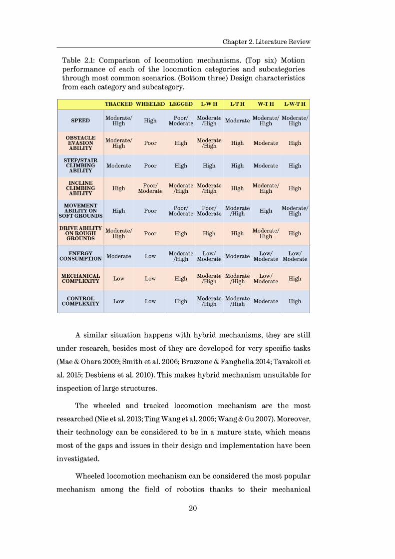
Table 2.1: Comparison of locomotion mechanisms. (Top six) Motion performance of each of the locomotion categories and subcategories through most common scenarios. (Bottom three) Design characteristics from each category and subcategory.
TRACKED WHEELED LEGGED L-W H L-T H W-T H L-W-T H
SPEED Moderate/High High Poor/
Moderate Moderate
/High Moderate Moderate/High
Moderate/High
OBSTACLE EVASION ABILITY
Moderate/High Poor High Moderate
/High High Moderate High
STEP/STAIR CLIMBING
ABILITY Moderate Poor High High High Moderate High
INCLINE CLIMBING
ABILITY High Poor/
Moderate Moderate
/High Moderate
/High High Moderate/High High
MOVEMENT ABILITY ON
SOFT GROUNDS High Poor Poor/
Moderate Poor/
Moderate Moderate
/High High Moderate/High
DRIVE ABILITY ON ROUGH GROUNDS
Moderate/High Poor High High High Moderate/
High High
ENERGY CONSUMPTION Moderate Low Moderate
/High Low/
Moderate Moderate Low/ Moderate
Low/ Moderate
MECHANICAL COMPLEXITY Low Low High Moderate
/High Moderate
/High Low/
Moderate High
CONTROL COMPLEXITY Low Low High Moderate
/High Moderate
/High Moderate High
A similar situation happens with hybrid mechanisms, they are still
under research, besides most of they are developed for very specific tasks
(Mae & Ohara 2009; Smith et al. 2006; Bruzzone & Fanghella 2014; Tavakoli et
al. 2015; Desbiens et al. 2010). This makes hybrid mechanism unsuitable for
inspection of large structures.
The wheeled and tracked locomotion mechanism are the most
researched (Nie et al. 2013; Ting Wang et al. 2005; Wang & Gu 2007). Moreover,
their technology can be considered to be in a mature state, which means
most of the gaps and issues in their design and implementation have been
investigated.
Wheeled locomotion mechanism can be considered the most popular
mechanism among the field of robotics thanks to their mechanical
Chapter 2. Literature Review
21
simplicity, low power consumption, high speeds, and stability (Nie et al. 2013;
Wang & Gu 2007). For these reasons wheeled locomotion mechanism are the
most appropriate mechanism to be implemented in a WCMR used in the
close inspection of large structures. Compared to wheeled locomotion,
tracked locomotion mechanisms are used in scenarios where a large area of
contact is needed, and the presence of big obstacles are a concern. Although
tracked mechanisms are not as fast and efficient as wheeled locomotion.
Therefore, if obstacles are not a significant concern, the best option is the
wheeled locomotion mechanism, furthermore, by implementing an
articulated frame to the MR, its ability to overcome complex obstacles is
enhanced.
The next section explores the types of adhesion mechanisms that can
be implemented in a WCMR, which along with locomotion mechanisms, are
the two key components that allow the MR to adhere and move around the
structure.
2.2.2. Adhesion mechanisms
The adhesion mechanism in the case of WCMR is the most important
part of the design, without it WCMR would not be able to perform or to keep
adhered on vertical structures. When we talk of adhesion mechanisms for
climbing robots, different principles can be discussed, e.g. magnetic,
electrostatic, vacuum, suction, elastomer, mechanical griping or
aerodynamic adhesion. A more detailed description and performance of
these mechanisms is presented next:
Electro-adhesion
Electro-adhesion makes use of electrostatic forces that act between the
target surface material (e.g. brick wall) and the electro-adhesive material
(elastomers) integrated to the locomotion mechanism (Legs, Wheels, etc.)
(International 2010). The electro-adhesive material is composed of embedded
micro conductive electrodes. By inducing opposite (positive and negative)

Chapter 2. Literature Review
22
charges in neighbouring electrodes, the electric field generated produces the
opposite charges in the target surfaces. Therefore, an electrostatic adhesive
force is produced between the electrodes and the target structure surface
(Prahlad et al. 2008). These working principle is comparable to electrostatic
chucks employed to grip silicon wafers, or other specialized grippers for
robotic handling of materials (International 2010).
Some of the advantages of the electro-adhesion technology are: 1.
adjustable adhesion to different surfaces with a low steady energy
consumption; 2. high adhesive forces on a diverse range of materials such as:
glass, concrete, plastics, drywall and wood); 3. quick attachment and
detachment response; 4. no damage produced in the substrates where it is
being used; and 5. ability to adapt to the surface coarseness, shape and cracks
that might be present (Prahlad et al. 2008; Wang et al. 2012)
On the other hand, the disadvantages of this technology are: 1. remains
an expensive technology; 2. it is still in development stage; 3. it has limited
payload capacity, only suitable for small and light MRs; and 4. it requires a
continuous supply of the power to maintain adherence (Prahlad et al. 2008;
Wang et al. 2012).
Dry adhesives/synthetic Gecko feet
Dry adhesion uses Van der Waals forces as adhesion mechanism. This
type of adhesives mimic the mechanism gecko lizards use for attachment
and detachment in nature. This is done by emulating the setae present in a
gecko’s toes (Peyvandi et al. 2013; Sahay et al. 2015; Murphy et al. 2011; Menon
et al. 2004). Surface material is not important, which means that this
technology will perform on most surfaces, similar to the electro adhesive
mechanism.
Dry adhesives, compared with the electro adhesive technology have
advantages such as: 1. no energy required to stay attached to surface (Prahlad
et al. 2008; Wang et al. 2012); 2. allows moderate velocities for locomotion
(Menon et al. 2004); 3. attachment and detachment occurs almost

Chapter 2. Literature Review
23
instantaneously (Menon et al. 2004; Lab n.d.; Santos et al. 2008); and 4. self-
cleaning mechanism of the setae (Menon et al. 2004).
In the case of the disadvantages of this technology, they are similar to
the case of the electro adhesion technology: 1. remains an expensive
technology; 2. it is still in the early stage of development; 3. it has limited
payload capacity, only suitable for small and light MRs; and 4. it requires a
continuous supply of the power to maintain adherence (Prahlad et al. 2008;
Wang et al. 2012).
Suction-vacuum and aerodynamic suction adhesion
This type of adhesion mechanism is one of the most used and earliest
mechanisms used in the field of WCMRs. The adhesion is accomplished by
suction cups, in which a vacuum pump generates the depressurization. This
produces a negative pressure which maintains the system adhered to surface
where it is being used (Bahr et al. 1996). This adhesion mechanism allows
bigger payloads for the MRs, compared to the two previous adhesion
mechanism. Even though this adhesion mechanism has been in use for few
decades, it has major drawbacks when compared with the other types of
mechanisms, such as: 1. it has to be used in MR that move on smooth surfaces
to avoid air leaking; 2. MR that use this technology are slow, noisy and heavy
due to the pumps that are carried; 3. have a high power consumption (Hu et
al. 2009; Kim et al. 2008; Xiao & Zhu 2009; Koo et al. 2013; Xiao et al. 2006;
Elliott et al. 2007); and 4. therefore require a tethered connection to a power
supply due to their high power consumption.
Mechanical adhesion
Robots with the mechanical adhesion mechanisms either grip or clamp
to the structures. Usually mechanical grippers, connectors or claws are
employed (e.g., small hooks) to keep attached on rough surfaces (Hu et al.
2009; Kim et al. 2008; Xiao & Zhu 2009; Koo et al. 2013; Xiao et al. 2006; Elliott
et al. 2007).

Chapter 2. Literature Review
24
This type of adhesion has the main disadvantage of potentially
damaging the areas where the attachment is performed. This limits its
employment to situations where the side effects of the clamping is not a
concern.
Magnetic adhesion mechanism
Magnetic adhesion mechanisms make use of Permanent Magnets (PM)
in order to generate the adhesion forces. Similarly, to electromagnetic
adhesion, magnetic adhesion is exclusively suitable for ferric structures. The
strength of the adhesive forces depends from the type and size of the PM
employed in the mechanism.(Carrara et al. 1992; Fischer et al. 2011; Tavakoli
et al. 2013; Tache et al. 2007).
This adhesion mechanism has the advantages such as: 1. strong
adhesive forces, allowing bigger payloads (Chu et al. 2010); 2. reliable form of
adhesion (Chu et al. 2010); 3. a relatively low cost compared to other adhesion
mechanisms due to its development maturity (Fernández et al. 2010; Khirade
et al. 2014); 4. works on most types of surfaces (e.g. rough, smooth) providing
the structure is ferric (Khirade et al. 2014); and 5. no energy required for
attachment/detachment (Chu et al. 2010; Khirade et al. 2014).
Some of the limitations this technology possess are: 1. it presents a
fixed adhesive force, that cannot be modified once a specific design is
selected (Chu et al. 2010); 2. MRs that use this technology may present a poor
manoeuvrability if the adhesive mechanism is not properly designed (Chu et
al. 2010); and 3. it is suitable exclusively for ferric structures.
Electromagnetic adhesion
This type of mechanism uses Electro Magnets (EM) for adhering
exclusively to ferric structures. The electromagnetic adhesion is generated
by the magnetic field produce by an electric current flowing in a solenoid.
Chapter 2. Literature Review
25
Compare to the magnetic adhesion mechanism, electro-magnets have
advantages such as: 1. large adhesion forces; 2. different forces can be
generated by a single mechanism; and 3. the adhesive force can be controlled
by varying the magnitude of the electric current applied to the solenoid.
The disadvantages of electromagnetic adhesion are: 1. power
consumption due to the continuous power supply needed to maintain a
desired adhesive force (Fischer et al. 2010; Fischer et al. 2011; Oliveira et al.
2010; Tavakoli et al. 2013; Zhang & Dodd 2011); 2. high temperature rise due
to the heat dissipation of the electric current flowing through the windings
of the solenoid; and 3. not suitable for untethered MR.
In order to have a more comprehensible comparison amongst the
described adhesion mechanisms, Figure 2.3 presents the advantages and
disadvantages for each adhesion technologies.
Based on Figure 2.3, the most appropriate technology for the
application on which the MR will perform can be selected. For example, in
the case of a smooth and clean surface, vacuum, suction, dry adhesive or
electro-magnetic can be used. But, the first two have the limitation of the
power consumption (the same case for electro-magnetic adhesion), which
becomes a big issue on cordless vehicles, as well as the noise generated. For
the case of dry adhesives, they tend to degrade with use over time.
For the specific situation of inspection on ferrite/ferric structures, the
Magnetic/Electro-Magnetic Adhesion Mechanism (M/EMAM) seems to be the
ideal choice. However, this adhesion mechanism has a major restriction in
the case of PM use, which is a fixed (passive) attraction force. This means
that it is not possible to vary the adhesion force. This becomes a major
problem in situations where this ability is required, e.g. to overcome certain
obstacles or move through a complex path. By employing EMs instead of PMs
we can solve these issues. However, another concern arises, which is the
power consumption. This is because an EM requires a permanent supply of
energy to generate the (active) adhesion forces, and this condition will lead
to a quick battery drain, for the case of cordless MRs. Some researchers
addressed this problem by designing a switchable device (ROCHAT et al.

Chapter 2. Literature Review
26
2010), which is a PM that can be rotated by a servo in different configurations
to vary its adhesion force. Although, the use of this switchable device is an
improvement, limitations exist, such as, mechanical complexity, control and
energy consumption of the servo.
Technology Weight
Repeated use on dusty
surfaces
Works on both rough
and smooth,
substrates
Energy require-ments
(attach-ment)
Energy require-ments
(detach-ment)
Works on wide
range of materials
Quiet / Non-
damaging / no residue
Cost
Electro-static
adhesion
Dry adhesives / Synthetic Gecko feet
Suction / vacuum
Aerodynamic Suction
Mechanical Adhesion
Electro-Magnets
Permanent Magnets
Electro-Permanent
Magnet Adhesion
Excellent
Performance Moderate Performance Poor
Performance
Figure 2.3: Comparison of existing adhesion technologies according to most common situations a WCMR might encounter. Electro Permanent Magnet adhesion will be presented section 2.3.1.
2.3. WCMR for inspection of ferric structures
In the specific scenario of ferric structures, different adhesion
mechanisms can be implemented in the development of a WCMR. Magnetic
adhesion offers a great advantage over other mechanisms.

Chapter 2. Literature Review
27
One of the first designs that used magnetic adhesion in a WCMR was
presented by (Hirose & Tsutsumitake 1992), where permanent magnet discs
were used as the wheels of the vehicle. Even though this design was
innovative and represented a step forward in the development of climbing
robots, it was limited to operate on flat surfaces, and was not able to
overcome obstacles.
A different approach employed in the design of an adhesion
mechanism for ferric structures was presented by (Grieco et al. 1998). In this
work researchers used electro-magnets combined with a legged locomotion
mechanism in the development of a WCMR that was capable to carry a high
payload (100kg) and able to manoeuvre in a complex 3-D scenario. The
advantage on the use of electro-magnets over permanent magnets is that EM
allows switching OFF and ON the adhesion force, making possible the legged
locomotion and consequently permitting the WCMR to overcome obstacles
and move in a 3-D scenario. The downside is, as in the case of the suction
technology, the need of a constant supply of energy in order to keep EMs
operative, constraining the range of operation.
Based on both principles, permanent magnets and electro-magnets,
numerous designs have been proposed. Most of them to perform a specific
task. Kalra et al. 2006 made use of PMs along with a tracked locomotion
mechanism in the design of a platform for inspection of oil tanks; or to work
in a similar scenario, W. Fischer et al. 2007 proposed a “mother-child”
configuration for inspecting very thin and fragile structures, in this
approach the “child” has magnetic wheels as adhesion mechanism, the
“mother” component has the function to help the “child” to overcome ridges
or any obstacle.
In recent years, there have been some studies in what are called
“Electro-Permanent Magnets” (EPMs), in the fields of programmable matter.
These are small magnetic actuators, or stepper-motors in the centimetre
scale. Although, the principle of EPM has been used in a big scale in the
improvement of electro-magnet lifters, its use in the centimetre scale is a
novel field of study.

Chapter 2. Literature Review
28
2.3.1. Electro-permanent magnets
This research is focused on the use of the EPM principle to develop a
novel adhesion mechanism for MRs, which is called “Electro-Permanent
Magnet Adhesion Mechanism” (EPMAM). This mechanism uses the
advantages from both EM and PM combined in a single device. As a result,
the new mechanism will have the ability to remain attached to a
ferric/ferromagnetic surface by means of the PM force (no power
consumption). In addition, it will have the ability to modify (increase,
decrease, or nullify) the attracting magnetic force. To do this it will only
require a small-width pulse (milliseconds) for modifying the magnetic field,
resulting in lowered power consumption. This mechanism means a huge
breakthrough in the field of magnetic adhesion, enhancing the mobility and
manoeuvrability of MRs. Figure 2.3 at the bottom of the Table there is a
comparison of magnetic/electro-magnetic versus electro-permanent magnet
adhesion mechanisms. It can be observed that the limitations concerning
power consumption, for electro-magnetic technology, and manoeuvrability
for both magnetic and electro-magnetic adhesion mechanism, are overcome
with the implementation of EPMAM.
The implementation of EPMs in the adhesion mechanism of WCMRs
could signify a major advancement. Allowing the MR to move through
intricate structures and to overcome obstacles that are not accessible with
conventional magnetic adhesion mechanisms.
Electro-permanent magnets history
EPMs were first mentioned in a paper in 1952 (Hadfield & Mawson 1952),
where they were part of the development of a spectrograph. It consisted of
an electro-magnet in parallel with a permanent magnet. By applying an
electrical pulse through the electro-magnet its magnetic field was added or
subtracted (depending of the polarity of the electrical pulse) from the
magnetic field of the permanent magnet. Thus, allowing the variation of the
Chapter 2. Literature Review
29
net magnetic field of the system as needed, giving more stability to the
system compared to only using an electro-magnet.
It was not until the 1980’s, with the development of new magnetically
semi-hard materials (e.g. Alnico or Alcomax), that innovative applications
started to be researched for this type of device. The main incentive was the
capability of an EPM to change its external magnetic field and maintain it
when the energy power supply is removed. Another advantage compared to
EMs is the low energy consumption, as they require a short electrical pulse
to change (increase or decrease) their magnetic adhesion force. In contrast
to electro-magnets, which require a constant supply power maintain their
magnetic adhesion force.
The main commercial use for EPM technology has been its
implementation in the electro-magnetic lifter field (Lee et al. 2008; Ltd 2014;
Cassing et al. 2008). The objective is to enhance the safety of the electro-
magnetic lifters, preventing them to fail when power supply (electrical
current) was removed from the EM, either by mistake or a failure in the
supply itself. In recent years, EPMs have been implemented in the design of
electro-magnetic locks, griping cargo systems and reconfigurable matter
(Piranda et al. 2013; Fu et al. 2012; Knaian et al. 2012).
In 1995, the basic working principle of EPMs was explored by Shirazee
and Basak to develop a suspension system for acquiring large air gaps in
suspended loads (Shirazee & Basak 1995). In this work, the arrangement of a
hard and a soft material, coiled with a magnetic wire is still used.
From 2000 to 2010, Chang Hyeon Ji et al. developed a micro optical
switch, which used a micro EPM to move a set of micro-mirrors (Ji et al.
2004). Tjahjo Pranoto et al. implemented an EPM in the mechanism of a
vibration suppression device (Pranoto et al. 2007). Jan Bydžovský et al.
proposed an EPM chuck, in which, the working principle of an EPM was
applied (Ondreička & Paľa 2010).
Up to now, the most extensive work on EPMs has been done by Knaian
(2010). He proposed the use of EPMs to construct connectors and actuators,
in a centimetre scale, to build “Micro Electro-Mechanical Systems” or MEMS.

Chapter 2. Literature Review
30
This work resulted in the development of: 1. “The Robot Pebbles” (Gilpin et
al. 2010) in the programmable matter field, which are 1cm cubes that use
EPMs to connect, communicate and share power with neighbouring cubes in
order to form shapes; 2. “Electro-Permanent Actuators” (Marchese et al.
2011), where EPMs are used to build small valves that are then employed to
construct actuators for soft robots. By applying a 5ms electrical pulse the
EPM valves are able to drive the pressurization and depressurization of
fluidics within the actuators; and 3. “The Milli-Motein” (Knaian et al. 2012),
which is a chain of programable matter with 1cm pitch, in the mini robot
field. This mini robot uses a mini stepper motor built with EPMs, which
enable motor to maintain its position without any energy consumption,
contrary to what happens with regular stepper motors.
The work of A. Knaian in these three devices has motivated others,
specifically in the field micro devices, for developing novel connection or
adhesion systems based on the EPM principle. Guoqiang Fu, et al. designed a
miniature switchable connection system for modular robots (Fu et al. 2012).
Andrew D. Marchese, et al. developed a programmable connection
mechanism for robots separated by a surface (Marchese et al. 2012).
In 2012, based on the thesis of Knaian, Peter Ward replicated the basic
experiments on EPMs presented by Knaian and suggested their possible use
as adhesion mechanism for climbing robots in ferric structures (Ward & Liu
2012). This work consisted in some experiments presenting the behaviour of
the EPMs in a centimetre scale and based on the results he proposed that
EPM technology could be integrated with different locomotion mechanism
employed in MR for climbing ferric structures. No further work was
undertaken.
Therefore, the work presented in the following chapters goes further
and explores in more detail the viability of different designs of MR with EPM
technology as adhesion mechanism.
EPMs theory and their working principle will be discussed in more
detail in Chapter 3.
Chapter 2. Literature Review
31
2.4. Concluding remarks
Through this chapter, it has been shown that in most of the designs of
a MR, there exist constraints that limit their development and
implementation. In the particular case of WCMR, what has limited their
development in the last decades are two main factors: 1. a versatile
locomotion system (Ting Wang et al. 2005; Jahanian & Karimi 2006); and 2.
an efficient adhesion mechanism (Schmidt & Berns 2013), (Miyake et al.
2007). However, the development of novel technologies in recent years, that
can be applied into both, the locomotion and adhesion mechanisms, have
contributed to overcome these constrains, up to some extent. This has
allowed developing systems that can be used in more than one specific
scenario. Therefore, the development of multitask vehicles capable of
moving in an unstructured scenario with the ability to overcome different
obstacles, although is a big challenge, will bring key benefits for the
inspection robots field
To conclude, it can be seen that there does not exist a general WCMR
as such. Additionally, the requirements for its development can be
contradictive, for instance, a small (light weighted) and fast WCMR is not be
able to carry a big payload or sensors, moreover, a system with a big payload
requires a strong adhesion mechanism that will likely render it slow and
difficult to manoeuvre.
In Chapter 3, the theory and working principles of the EPMs are
introduced. A set of simulations and the corresponding physical
experiments are performed and their results presented in order to validate
the EPM concept as a viable adhesion mechanism for WCMRs.
Chapter 2. Literature Review
32

33
Chapter 3
Electro-Permanent Magnets as an Adhesion Mechanism
Electro-Permanent Magnets (EPM) have the potential to be
implemented as part of the adhesion mechanism in WCMRs. In the present
chapter the theory behind the main concepts that enable the operation of
EPMs is presented in Section 3.1. Then, the working principles of EPMs, and
the OFF and ON states along with the variable magnetic adhesion, are
presented in Section 3.2. Once the theory and working principles are
presented, a set of Finite Element Analysis (FEA) simulations and
corresponding experiments are performed with the purpose to validate the
viability of EPMs as adhesion mechanism, and are presented in Section 3.3.
Finally, results from both, simulations and experiments, are discussed and
the concluding remarks are presented in Section 3.4.
3.1. Theory
Formal theory for Electro-permanent magnet (EPM) is limited at the
moment (Marchese et al. 2011; Knaian et al. 2012; Knaian 2010; Marchese et
al. 2012; Ondreička & Paľa 2010). However, based in the working principles of
Permanent Magnets (PM) and ElectroMagnets (EM) the working principle of
EPMs can be deducted.

Chapter 3. Electro-Permanent Magnets as an Adhesion Mechanism
34
An Electro-permanent magnet (EPM) is a bi-stable, solid-state magnetic
device. It has the capability to be switched OFF and ON by applying a short
electrical pulse. An EPM is composed of a particular arrangement of two
magnetically different materials, one hard and one semi-hard. Both
materials are PMs which are coiled together with magnetic (enamelled) wire,
and topped at their magnetic poles with ferromagnetic keepers, Figure 3.1.
Figure 3.1: Electro-Permanent Magnet design: yellow, NdFeB PM (hard magnetic material); blue, Alnico PM (semi-hard magnetic material).Both PMs are coiled together with enamelled wire; capped with two ferromagnetic (steel) keepers placed at the poles of the PMs.
A key property of PMs is their coercivity, this property determines how
magnetically hard or soft a PM is. Moreover, the difference in coercivity
between the two PMs is what enables the bi-stability in EPMs
3.1.1. Important concepts
Magnetic Fields
The space adjacent to any magnet (electromagnet or permanent
magnet) where magnetic forces, which have a direction and a magnitude, act
is called the magnetic field. There exist two, closely related, fields that are
denoted by B and H.
Chapter 3. Electro-Permanent Magnets as an Adhesion Mechanism
35
The B-field, or magnetic flux density, is the force on a moving charge
and its units in the SI s the Tesla and is produced by currents according to
Ampere’s Law and Biot-Savart Law.
The H-field, or magnetic field strength, is the field produced when a
magnetic field B passes through a magnetic material. The magnetic field
strength SI units are the A/m (ampere per meter).
Both, B-field and H-field are proportional and their relationship is
determined by the following equation:
𝐵 = 𝜇𝑚𝐻 (3.1)
and
𝜇𝑚 = 𝐾𝑚𝜇0 (3.2)
where 𝜇0 is the magnetic permeability of free space and 𝐾𝑚 is the relative
permeability of the material where the magnetic field is acting (Nave 2017).
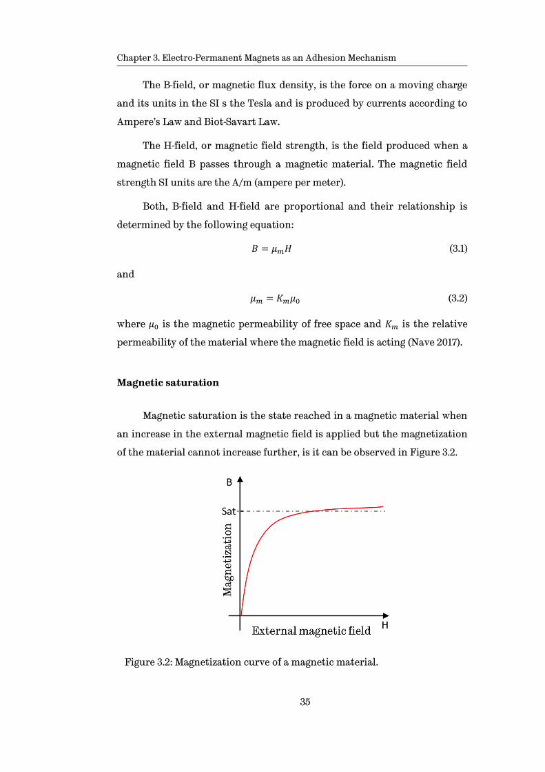
Magnetic saturation
Magnetic saturation is the state reached in a magnetic material when
an increase in the external magnetic field is applied but the magnetization
of the material cannot increase further, is it can be observed in Figure 3.2.
Figure 3.2: Magnetization curve of a magnetic material.

Chapter 3. Electro-Permanent Magnets as an Adhesion Mechanism
36
Coercivity
For ferromagnetic materials, coercivity measures the ability of the
materials, previously driven to saturation, to resist demagnetization in the
presence of an external magnetic field. This value is denoted Hc. Table 3.1
shows typical values of coercivity of three magnetically different materials.
Magnetically hard materials have high coercivity, which means a
strong magnetic field is required in order to demagnetise them. Magnetically
semi-hard materials have medium coercivity, and are therefore relatively
easy to demagnetise by applying an external magnetic field. On the other
hand, soft materials have low coercivity, thus they do not retain
magnetization, which means they lose it as soon as the external magnetic
field is removed.
Table 3.1: Typical values of coercivity for different magnetic materials (Online 2016).
Material Coercivity Hc (kA/m)
Neodymium (NdFeB) 880 - 960 Magnetically hard
Alnico (AlNiCo) 46 - 126 Magnetically semi-hard
Mild Steel 0.15 - 0.50 Magnetically soft
Inductance of a solenoid
Inductance is the opposition of a conductor to the change of the
electrical current flowing through it and the SI units are the Henry (H). A
solenoid or inductor is a device made from loops (or windings) of wire. If for
a given solenoid the number of loops is increased, then for the same current
flowing through it, the magnetic flux will increase hence its inductance, as
shown in the following equation (Nave 2017):
𝐿 = 𝜇0𝑁2𝐴
𝓁 (3.3)
Chapter 3. Electro-Permanent Magnets as an Adhesion Mechanism
37
where L is the inductance in henries, 𝜇0 is the permeability of free space, N
is the number of turns in the solenoid, A is the inner core area of the solenoid
in square meters and 𝓁 is the length of the solenoid in meters.
Electric current and magnetic field in a conductor
When an electric current flows through a conductor, a magnetic field
is generated around the conductor. The intensity of the magnetic field is
proportional to the magnitude of the electric current. This magnetic field
forms in concentric circles perpendicular to the direction of the electric
current.
Now, when the conductor is coiled forming a solenoid the magnetic
flux lines around the conductor are distorted forming closed loops around
the whole solenoid. As a result, the pattern produced by the magnetic flux
lines, resembles the magnetic field in a permanent magnet bar, with a higher
concentration of magnetic flux lines inside of the solenoid.
When the electric current flowing in a coil is fixed (no changes over
time), the magnetic field generated by the solenoid is also constant. On the
other hand, when a change in the magnitude of the current is produced, the
magnetic field will vary in the same proportion. Furthermore, according to
Faraday’s law of electromagnetic induction, a changing magnetic field in a
coil will induce an electromotive force (emf) across the coil. In addition with
Lenz’s law of electromagnetic induction, when an emf is induced, in
accordance to Faraday’s law, the direction of the emf will oppose the source
from which it is produced. This is also known as inductance.
Due to the self-inductance present in every inductor, when a voltage is
applied to the terminals of the solenoid the electric current that flows
through the windings increases in an exponential way, Figure 3.3.
𝑖(𝑡) =𝑉
𝑅(1 − 𝑒
𝑅
𝐿𝑡) (3.4)
Chapter 3. Electro-Permanent Magnets as an Adhesion Mechanism
38
where i(t) is the current flowing through the windings, V is the voltage
applied to the solenoid terminals, R is the resistance of the solenoid and L is
the inductance of the solenoid.
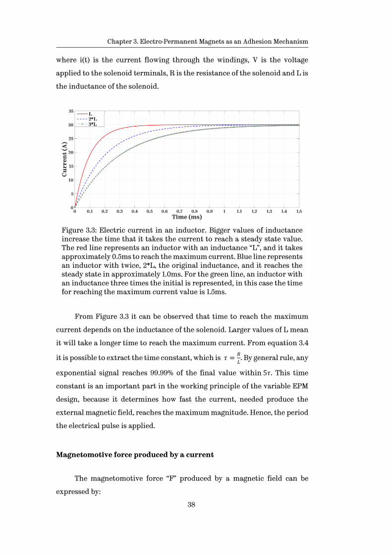
Figure 3.3: Electric current in an inductor. Bigger values of inductance increase the time that it takes the current to reach a steady state value. The red line represents an inductor with an inductance “L”, and it takes approximately 0.5ms to reach the maximum current. Blue line represents an inductor with twice, 2*L, the original inductance, and it reaches the steady state in approximately 1.0ms. For the green line, an inductor with an inductance three times the initial is represented, in this case the time for reaching the maximum current value is 1.5ms.
From Figure 3.3 it can be observed that time to reach the maximum
current depends on the inductance of the solenoid. Larger values of L mean
it will take a longer time to reach the maximum current. From equation 3.4
it is possible to extract the time constant, which is 𝜏 =𝑅
𝐿. By general rule, any
exponential signal reaches 99.99% of the final value within 5𝜏. This time
constant is an important part in the working principle of the variable EPM
design, because it determines how fast the current, needed produce the
external magnetic field, reaches the maximum magnitude. Hence, the period
the electrical pulse is applied.
Magnetomotive force produced by a current
The magnetomotive force “F” produced by a magnetic field can be
expressed by:
Chapter 3. Electro-Permanent Magnets as an Adhesion Mechanism
39
𝑭 = 𝑵𝑰 (3.5)
𝑭 = 𝑯𝒄𝓵 (3.6)
where N is the number of turns in the coil, I is the current flowing through
the coil, HC is the intensity of the magnetising field and 𝓁 is the mean length
of the coil.
Both equations can be solved for HC in terms of N, I and 𝓁
𝑯𝒄 =𝑵𝑰
𝓵 (3.7)
From eq. 3.7 it is can be deduced that the intensity of the magnetic field
generated by the coil depends from the number of turns N in the coil, the
amplitude of the current I flowing through them, and its mean length.
Considering N and L fixed parameters in an EPM, Hc depends from the
magnitude of the electric current I.
Force calculation
In order to compute the holding force produced between the keepers
and the target, is possible to use equation derive by (Knaian 2010):
𝐹 =𝐵𝑠𝑎𝑡
2 𝑎𝑏
𝜇0 (3.8)
where F is the magnetic force, 𝜇0 is the permeability of free space, 𝐵𝑠𝑎𝑡 is the
saturation value for the flux density of the PMs and ab is the keepers
bottom area.
3.2. Working principles
Coercivity can be considered as the crucial property in the
development of EPMs, through the combination of two PMs with different
coercivity. If a single type of PM, either magnetically hard or semi-hard, is
used to build an EPM, it will result in a device with undesirable
characteristics. The two most important affected characteristics are the

Chapter 3. Electro-Permanent Magnets as an Adhesion Mechanism
40
magnetic force and the energy consumption of the device, depending on the
PM employed (magnetically hard or semi-hard).
For example, if the PM used is made of a magnetically hard material
(e.g. NdFeB), it will exhibit strong adhesive force. However, the energy
required for switching the adhesive force OFF and ON would be quite large,
and thus not suitable to be employed in a WCMR.
On the other hand, if the PM is made of a magnetically semi-hard
material, the energy required for performing the switching between states is
reduced. But the adhesive force would not be enough to keep the whole
device attached to the structure. Furthermore, the EPM would be vulnerable
to influence of any external magnetic field as it may easily be demagnetised.
However, if both types of PMs (magnetically hard and semi-hard PM)
are assembled into a single device, the strengths of both PMs will add up, and
their weaknesses nullified. In other words, the resulting EPM would exhibit
a strong adhesive force, small energy consumption and would not be
influenced by external magnetic fields.
Based on this, the EPM device shown in Figure 3.1 can be implemented.
The device consists of two magnetically different PMs, one hard PM (e.g.
NdFeB) and the other semi-hard PM (e.g. Alnico). Both PMs are coiled
together with magnetic (enamelled) wire and topped at their magnetic poles
with two pieces of a magnetically soft material (e.g. iron, electric steel,
hiperco), which act as keepers for the EPM.
3.2.1. OFF and ON configurations
An EPM has two basic configurations, OFF and ON, Figure 3.4. In both
cases the PMs are placed in parallel with respect to the orientation of their
magnetic fields. The ON configuration occurs when both magnetic fields are
pointing in the same direction (both north poles are facing the same keeper,
the same with the south poles).

Chapter 3. Electro-Permanent Magnets as an Adhesion Mechanism
41
Figure 3.4: EPM basic configurations. (a) ON State - Both PMs are in parallel and their magnetic flux lines (blue and red arrows) are aligned in the same direction. The magnetic fluxes add up and flow through the left keeper. Then, the magnetic flux lines are exerted from the bottom of the left keeper and flow through the target re-entering the EPM through the bottom of the right keeper, closing the magnetic circuit. The magnetic flux coming out and in from the bottom of the keepers produces the attracting force on the target. (b) OFF State - PMs are in parallel, similar to the ON state, however, their magnetic flux lines are aligned in opposing directions (blue and red arrows). In this case, the magnetic flux lines coming out of the north pole of the top PM flow through the south pole of the bottom PM, using just the upper part of the left keeper. The magnetic flux comes out of the bottom PM’s north pole and re-enters into the upper PM’s south pole closing the magnetic circuit. As a result no external magnetic flux is generated and consequently no attracting magnetic force.
The magnetic flux lines coming out of each north pole add up, flow
through the keeper next to them and come out at the bottom of the keeper.
The magnetic flux lines then re-enter the EPM from the bottom of the keeper
capped to the PMs’ south poles. The exerted external magnetic field produces
an attracting magnetic force that is used by the device to adhere to a
ferromagnetic surface.
The OFF configuration forms when the magnetic flux lines of both PMs
have opposite directions with respect to each other. In this case, magnetic
flux lines coming out of the north pole of the first PM go into the south pole
of the second PM that is next to it, through the upper part of the keeper. The
magnetic flux flows through the PM and comes out again through the north
pole and enters in the adjacent PM south pole. Therefore, the magnetic flux
Chapter 3. Electro-Permanent Magnets as an Adhesion Mechanism
42
is kept in a closed loop inside the EPM and no external magnetic field is
generated, consequently no attracting magnetic force is produced.
Transitions between states
In order to perform the transitions from OFF to ON states, and vice
versa, an electrical current pulse must be applied to the windings (solenoid)
coiled around the PMs. This current pulse is indispensable to generate the
external magnetic field that re-magnetises the Alnico magnets, reverting the
direction of the PM’s magnetic field. Which enables the main property of
EPMs, switching between OFF and ON states. The operation hysteresis of an
EPM in an OFF-ON working cycle is presented in Figure 3.5.
In order to perform the switching between the OFF and ON states an
electrical pulse must be applied through the enamelled wire (coil). When the
initial condition of the EPM is the OFF state and the electrical pulse has a
positive polarity the EPM will switch from the OFF to the ON state.
Conversely, when the initial condition of the EPM is the ON state and the
pulse has a negative polarity the EPM will transition from ON to OFF state.
The generated external magnetic field must to be strong enough to drive the
Alnico5 PM to saturation. Due to the different coercivity, between the PMs,
the magnetic field will not affect the NdFeB magnet because of its high
coercivity.
In order to ensure that the Alnico PM is driven to saturation, the
external magnetic field must be at least twice the value of the PM’s intrinsic
coercivity Hc. As shown in Section 3.1.1 the intensity of the magnetic field
produced by a solenoid depends proportionally on the electric current,
flowing through the windings, and the number of turns of the solenoid.
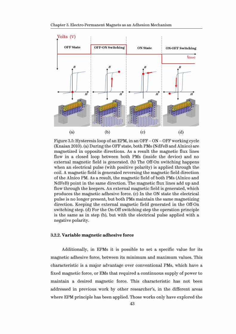
Chapter 3. Electro-Permanent Magnets as an Adhesion Mechanism
43
Figure 3.5: Hysteresis loop of an EPM, in an OFF – ON – OFF working cycle (Knaian 2010). (a) During the OFF state, both PMs (NdFeB and Alnico) are magnetized in opposite directions. As a result the magnetic flux lines flow in a closed loop between both PMs (inside the device) and no external magnetic field is generated. (b) The Off-On switching happens when an electrical pulse (with positive polarity) is applied through the coil. A magnetic field is generated reversing the magnetic field direction of the Alnico PM. As a result, the magnetic field of both PMs (Alnico and NdFeB) point in the same direction. The magnetic flux lines add up and flow through the keepers. An external magnetic field is generated, which produces the magnetic adhesive force. (c) In the ON state the electrical pulse is no longer present, but both PMs maintain the same magnetizing direction. Keeping the external magnetic field generated in the Off-On switching step. (d) For the On-Off switching step the operation principle is the same as in step (b), but with the electrical pulse applied with a negative polarity.
3.2.2. Variable magnetic adhesive force
Additionally, in EPMs it is possible to set a specific value for its
magnetic adhesive force, between its minimum and maximum values. This
characteristic is a major advantage over conventional PMs, which have a
fixed magnetic force, or EMs that required a continuous supply of power to
maintain a desired magnetic force. This characteristic has not been
addressed in previous work by other researcher’s, in the different areas
where EPM principle has been applied. Those works only have explored the
Chapter 3. Electro-Permanent Magnets as an Adhesion Mechanism
44
EPM main characteristic of being able to be switched OFF and ON by single
electrical pulse. Leaving out the capability of EPM to vary their magnetic
adhesive force between OFF and ON values.
Adjustable magnetic adhesive force is a major breakthrough in the area
of magnetic adhesion mechanism for ferric structures. Such adhesion
mechanism enables WCMR to overcome complicated transitions or complex
obstacles by varying its adhesive force as required.
To achieve a specific value of magnetic adhesive force the amplitude of
the electric current pulse has to be varied. Taking into account equation 3.4,
if the amplitude of the electric current pulse applied to the windings is
varied, Alnico PM can be partially magnetised. Which results in a particular
value for the magnetic adhesive force, between zero and maximum values.
3.2.3. Characteristics of the EPMs
EPMs have the following characteristics (Knaian 2010):
• Bi-stability: They can maintain the maximum or minimum magnetic
adhesive force after the switching pulse has been applied. Therefore,
they do not need a continuous supply of energy.
• Switching: EPMs have a switching period in the order of milliseconds
to change states. For practical terms this can be considered as
instantaneous.
• Operation period: EPMs are suitable for applications where the
switching frequency is small and no repeated changes of states (ON-
OFF or OFF-ON) in short time lapses are needed.
• Power consumption: EPMs require just a short electrical pulse
(lasting a few milliseconds) to switch between states and maintain the
final state. The instantaneous power required is just a fraction of what
an EM needs to perform the same task (switching between OFF and ON
states and preserving the final state). This characteristic translates to

Chapter 3. Electro-Permanent Magnets as an Adhesion Mechanism
45
significant savings in the power required for their operation compared
with other technologies.
• Low increase in temperature: EPMs have a low temperature rise due
to their short working cycle (they are active for a very short periods of
time). The main components, PMs and Steel Keepers, also act as a heat
sink dissipating the heat generated through the windings.
• Scalability: EPMs are scalable in two ways: 1. volume versus power;
and 2. area versus attracting force. This means that the power needed
for the switching scales with volume, whilst, the magnetic attraction
force varies with the poles area (Knaian 2010). Increasing the area of
the poles whilst reducing the volume of the EPM results in an increase
of efficiency, with higher adhesion force and smaller power
consumption.
3.3. Validation of the electro-permanent magnet concept
In order to validate the EPM concept and its implementation as an
adhesion mechanism for WCMRs, a basic device is constructed using off-the-
shelf components. Once the device is built the corresponding CAD model
with the actual components dimensions is created with the intention to
perform FEA simulations using ANSYS Maxwell software and the
corresponding experiments are conducted to validate the EPM concept.
To physically observe the magnetic field in the EPM, a Magnetic Field
Viewing Film (MFVF) was used. The latter is a sheet coated with micro-
capsules containing nickel chips suspended in oil. In the presence of a
magnetic field, the MFVF becomes darker in areas where the magnetic flux
lines are perpendicular to the sheet. On the other hand, when magnetic flux
lines parallel to the sheet, that area will appear bright.
Section 3.3.1 describes the components used for the experiment and
Section 3.3.2 explains equipment and setup employed to perform the
experiments.

Chapter 3. Electro-Permanent Magnets as an Adhesion Mechanism
46
3.3.1. Basic configuration and components of the EPM
The device constructed for validation purposes consists of two 5mm
diameter x 20mm PMs rods (one Alnico5 and the other NdFeB N42) and two
keepers made of mild steel, Figure 3.6 (a). Both PMs were placed in parallel
one on top of the other and capped at both ends with the steel keepers as
shown in Figure 3.6 (b). To complete the basic EPM device, both PMs are
coiled with enamelled wire Figure 3.7.
Figure 3.6: Components of the EPM used for validation of the concept. (a) EPM components: one Alnico5 PM, one NdFeB N42 PM and two mild steel keepers. (b) Basic EPM configuration: NdFeB PM is placed on top of the Alnico PM, both PMs are topped with a keeper at each magnetic poles. (Coin shown for scale purposes).
Enamelled wire gauge
Enamelled wire (also magnet wire) is a coated wire made from copper
or aluminium. This type of wire is mainly used in the fabrication of
inductors, motors, electromagnets or transformers, among many other
applications. Similar to other wires, enamelled wire is classified by its
diameter by either American Wire Gauge (AWS) or Standard Wire Gauge
(SWG).
Copper and aluminium, as any material, present a natural resistance
to the flow of an electrical current. This resistance R can depends on the

Chapter 3. Electro-Permanent Magnets as an Adhesion Mechanism
47
resistivity of the material 𝜌, length of the wire 𝓁 and the cross sectional are
of the wire
R =ρ𝓁
A (3.9)
From eq. 3.9, it is possible to observe that resistance is proportional to
the length wire and inversely proportional to the cross sectional area.
Therefore, the selection of most appropriate wire for the EMP wheel design
is crucial. A wire with a small cross sectional area allows to fit more turns in
a fixed length, however its resistance increases which reduces the maximum
possible current that can flow through it. On the contrary, a large cross
sectional area means lower resistance; however, less turns can be fitted in a
fixed length. Table 3.2 shows seven wire gauges that are suitable to be used
in an EPM wheel design.
The diameter of the AWG 26 enamelled wire is 0.404mm, which only
allows to fit 44 turns around the 20mm long PMs, in one layer. In order to
produce a sufficient magnetomotive force, three layer are coiled around the
PMs resulting in 132 turns. Once the basic EPM is built, the corresponding
CAD model was created, Figure 3.7. The purpose of the latter is to perform
the FEA simulations needed for the validation.
Table 3.2: AWG enamelled copper wire size and data chart for the seven wire gauges considered for the EPM wheel design.
Gauge R
(Ω/m) Diameter
Weight (gr/m)
32 0.5383 0.202 0.2846
30 0.338 0.255 0.4601
28 0.22 0.321 0.7227
26 0.133 0.405 1.1443
24 0.084 0.511 1.8349
22 0.053 0.644 2.8944
20 0.021 0.812 4.6013

Chapter 3. Electro-Permanent Magnets as an Adhesion Mechanism
48
Figure 3.7: Basic EPM device coiled with 132 turns of AWG 26 enamelled wire. (a) Physical model built with off-the-shelf components (NdFeB N42 and Alnico5 PMs, enamelled wire and mild steel keepers), for experiments. (b) CAD model for FEA with equivalent dimensions for simulation purposes.
3.3.2. Equipment and experimental setup
For the case of the experimental validation the following equipment is
used for performing the measurements and for controlling the pulse applied
to the coil:
Load cell
An “S-Beam” load cell, from Omni instruments1, is used for
measurement of the force produced by the EPM. The model DBBSM-25KG,
Figure 3.8, has a bidirectional rated capacity of -25kg to +25kg. These type of
load cells are used for tension and compression force measurements.
1 http://www.appmeas.co.uk/pdf/load-cells/DBBSM.pdf

Chapter 3. Electro-Permanent Magnets as an Adhesion Mechanism
49
Figure 3.8: S-Beam bidirectional load cell used to measure the magnetic adhesive force generated by the EPM device. The load cell measures the pull exerted by the attached EPM device.
Motor driver
Due to the high currents needed to produce the external magnetic field
in the coil, a dual dc motor driver was selected for performing the switching.
The MD30C R2 model from Cytron Technologies2, shown in Figure 3.9, has
the following characteristics:
• Has a bidirectional control, which is essential for the attachment and
detachment. A pulse with positive polarity is required for the OFF-ON
switching. Conversely, a pulse with negative polarity enables the ON-
OFF switching.
• Supports a continuous current of 30amps, with a maximum peak
current of 80Amp for one second. The maximum pulse lengths are
estimated to be no greater than 50ms (for experimental purposes), thus
is safe to use the maximum 80Amp capacity.
2 http://www.cytron.com.my/p-md30c

Chapter 3. Electro-Permanent Magnets as an Adhesion Mechanism
50
Figure 3.9 Bidirectional motor driver, MD30C R2, used for applying the electrical pulses to the EPM windings. Supports a continuous current of 30amps and a peak current of 80amps for one second.
Data acquisition and control signal generation
For the acquisition of the data, and sending the control signal to the
motor driver to perform the switching, a National Instruments NI cDAQ 9178
chassis is employed. For acquiring the force data from the load cell a NI 92013
8 channels module, and for controlling the motor driver the NI 92634 4
channel module are used, Figure 3.10. Both modules have a sampling rate of
100 kS/s and a ±10v input and output range, respectively.
Along with the NI cDAQ chassis and modules, a simple code is
programed in LabView5 to simultaneously apply the electrical pulse to the
coil’s windings, and acquiring the adhesive force generated by the EPM.
3 http://www.ni.com/datasheet/pdf/en/ds-184 4 http://www.ni.com/datasheet/pdf/en/ds-59 5 http://www.ni.com/labview/

Chapter 3. Electro-Permanent Magnets as an Adhesion Mechanism
51
Figure 3.10: Chassis NI cDAQ 9178 with one analogue input module NI 9201 for acquiring load cell data. And one analogue output module NI 9263 for sending the signal to the motor driver for controlling the electrical pulse applied to the solenoid.
Experimental Setup
The experimental setup for the validation of the EPM concept is
presented in Figure 3.11. The EPM is attached to the load cell which holds it
over a steel plate. The EPM is connected to the motor driver that generates
an electric current pulse, whose power is supplied by a LiPo battery. The
motor driver is controlled by the NI 9263 output module inserted into the NI
cDAQ chassis. The data from the load cell is acquired by the NI 9201 module,
also inserted into the NI cDAQ chassis. The chassis is connected to a PC, via
USB, that controls the period of the pulse and stores the data from the load
cell with the help of a graphical interface programed in LabView.
Experimental protocol
The main objective of the experiments is to validate the working
principle of EPMs. For this particular case the independent variable is the
length of the electrical pulse, expressed in milliseconds (ms), and the
dependent variable is the magnetic force produced by the EPM, expressed in
kilograms (Kg).

Chapter 3. Electro-Permanent Magnets as an Adhesion Mechanism
52
Once the experimental setup described previously is set, an electrical
pulse is applied to the EPM’s winding. Using LabView and NI-Daq chassis,
the electrical pulse applied and the magnetic force (generated by the EPM)
are be recorded for further analysis.
For the OFF-ON transition a 20ms electrical pulse is applied (with the
corresponding polarity) in order to set the EPM to its OFF state. Then a set
of electrical pulses is applied with lengths that start with 0.1ms with 0.1ms
increments. Each length step is repeated 5 times and the final force (after the
transient behaviour has settled) is recorded and then averaged. After each
pulse is applied and the data recorded an 20ms pulse with inverse polarity is
applied in order to reset the EPM to its initial state before the next pulse is
applied.
For the ON-OFF transition the same procedure is followed, but
previously setting the EPM into its ON state.
Figure 3.11: Experimental setup for validation the EPM concept. Module NI 9263 sends the control signal to the motor driver, which delivers an electrical current pulse to the EPM. The EPM switches from OFF to ON state and gets attracted the steel plate below it. Load cell measures the force of the pull generated by the EPM and the data is acquired by the NI 9201 module.

Chapter 3. Electro-Permanent Magnets as an Adhesion Mechanism
53
Simulation Setup
For the case of the FEA simulations performed for the validation,
ANSYS Maxwell 2015.2 software is used. Maxwell software is specifically
designed for FEA simulations in the electromagnetics field. It allows to
obtain magnetostatic, and transient solutions.
In any FEA simulation setting the appropriate mesh is crucial for
obtaining accurate results. One of the advantages of Maxwell is that the
software performs the meshing process through adaptive meshing refining.
The user only needs to set the desired percentage of accuracy for the final
solution, the percentage of mesh refinement after each pass, and the number
of passes after which the simulation is stopped if convergence of the desired
solution is not reached.
It is possible to decrease the simulation time, if certain mesh
refinement operations are performed in areas where the user knows include
higher concentrations of the fields. Figure 3.12 shows an example of the
adaptive mesh refinement performed by Maxwell software with a setting of
20% refinement per pass and 0.35% percent error as solution target. Solution
was achieved in 5 passes and 7 minutes.

Chapter 3. Electro-Permanent Magnets as an Adhesion Mechanism
54
Figure 3.12: Results from an adaptive mesh refinement in ANSYS Maxwell 2015.2. (a) Initial mesh without any initial mesh operations. (b) Final mesh after 5 passes with a 20% refinement per pass and 0.35% final error as a target solution.
3.3.3. Simulation and experimental results: basic OFF and ON
configurations
The two basic configurations (OFF and ON described in Figure 3.4) were
explored. Using only the main components, shown in Figure 3.6(a), the FEA
simulation in the ANSYS Maxwell software and their corresponding physical
experimentation were implemented. Qualitative results are presented
showing the behaviour of the EPM, together with quantitative results of the

Chapter 3. Electro-Permanent Magnets as an Adhesion Mechanism
55
adhesive force. Both results are shown with the objective of verifying that
the physical experimentation correlate to simulations performed with FEA.
Qualitative results
From the FEA simulations, shown Figure 3.13, it is observed that in the
case for ON configuration the magnetic flux lines flow through the steel
keepers and generate an external magnetic field at the bottom the keepers.
This magnetic field will magnetise any ferromagnetic object placed close to
the EPM, producing a magnetic adhesive force. For the OFF case the
magnetic flux lines are kept in a closed loop inside the EPM, as result no
external magnetic field is produced. Consequently, no magnetic adhesive
force is generated outside the device.
Figure 3.13 Qualitative results from quantitative FEA simulation of the EPM two basic states. Arrows represent the magnetic flux lines and the flowing direction. (a) In the ON state both PMs are magnetised in the same axis direction resulting in their magnetic flux lines adding up and flowing through at the steel keepers. This flow is directed to the steel target producing a magnetic attracting force on between the EPM and the target. (b) For the OFF state, the PMs’ magnetisation is in opposing directions on the same axis, which results in their magnetic flux lines flowing in a closed loop between the Alnico and NdFeB PMs, inside the EPM. As a result, no magnetic adhesion force is generated.
In Figure 3.14, the physical display of the magnetic field interaction is
shown, for the OFF and ON states. When the EPM is in the ON state magnetic
flux flows through the keeper and steel piece (placed as target). By placing

Chapter 3. Electro-Permanent Magnets as an Adhesion Mechanism
56
the MFVF over the EPM, three main dark areas are shown (left and right
keepers, and steel target), indicating the presence of the magnetic field.
Similarly, when the MFVF is placed on the EPM in OFF state, only the area
where the PMs are present, become dark. This demonstrates that the
magnetic field is inside the EPM, flowing in a closed magnetic circuit
between the PMs. Additionally, in Figure 3.15 shows in a qualitative way the
effect of the adhesive force for both, OFF and ON states, over a group of steel
pieces stacked together with a combined weight of 1.268kg.
Figure 3.14: Qualitative results from physical validation. Red arrows indicate the direction of magnetic field flux lines, red dashed ovals indicate the interaction of the magnetic field of the Alnico and NdFeB PMs. (a) For the ON state it is observed that the magnetic flux flows through the keepers (dark areas) and then through the steel piece at the bottom. (b) On the other hand, in the OFF state magnetic flux is kept in a closed loop between both PMs.

Chapter 3. Electro-Permanent Magnets as an Adhesion Mechanism
57
Figure 3.15: Experimental demonstration of the holding magnetic adhesive force. Magnetic field is exerted from the EPM producing a magnetic adhesive force. The EPM can easily hold a 1.268kg pile of steel pieces attached to the device.
Quantitative results
From the same experiments and simulations, actual values for the
magnetic adhesive force were also obtained, Table 3.3. The experimental
result corresponds to the average value of five independent experiments.
Table 3.3: Comparison of the magnetic adhesive forces obtained through simulations and experiments
State Simulation Experimental
ON 1.42 Kg 1.39 kg
OFF 0 Kg 0 Kg

Chapter 3. Electro-Permanent Magnets as an Adhesion Mechanism
58
Both, simulation and experimental results demonstrated in a qualitative
and quantitative way, the working operation and the interaction of the
magnetic fields inside the EPMs. In order to fully validate the concept of
EPMs as an adhesion mechanism, its switching behaviour was also
corroborated, as described next.
3.3.4. Switching between states and variable magnetic adhesive force
The EPM device and CAD model shown in Figure 3.7 were employed for
the validation of the OFF-ON and ON-OFF switching. The setup for the
experiments and simulation was the following: voltage applied Vin = 11.84V
and pulse width t = 2.5ms. The electrical circuit is shown in Figure 3.16. The
value of the resistance R depends on the gauge of the magnet wire and its
length. For this particular case, a 26AWG magnet cable was employed with a
length of 7.59mts and 132 turns. The resistance measured was R = 0.57 ohms.
Figure 3.16: Electrical diagram for both experiment and simulations. R and L are the same component, coil or winding, it was split into its resistance and inductance parts due to software requirements to perform the simulation.
In the case of the physical experiments a LiPo battery was employed as
source of power to minimise the noise in the measurements. It was found
that the DC power supply used initially introduced the frequency of the
electrical mains, and incremented the level of noise in the measurements.

Chapter 3. Electro-Permanent Magnets as an Adhesion Mechanism
59
OFF-ON switching
Simulations results, Figure 3.17 (b) red dashed line, show that for this
design, saturation is reached in approximately 1ms. Applying longer pulses
does not add extra adhesive force to the device. Once the EPM has reached
saturation, 1ms for this case, the remaining time the adhesive force keeps
constant until the pulse is removed, at 2.5ms.
The magnetic adhesive force switched from 0Kg to 1.42Kg by applying
just a 2.5ms electrical pulse, with a power consumption of 0.187mWh. In the
same way, results from the experiment showed a final magnetic adhesive
force of 1.39Kg after switching from OFF to ON.
The blue line in Figure 3.17 (b), represents the experimental result, it
can be observed that there exists a discrepancy in the transient switching
between simulation and real experiment. There exists a 0.6ms delay in the
measured force after the external pulse is applied. The reason for this delay
is the type of sensor that was employed to measure the force an S-Beam load
cell. The “S” shape of the sensor causes it to behave like a spring, when the
load receives an impulse excitation. Therefore, explaining the delay at the
beginning of the measurement and the oscillations after the excitation is
removed, Figure 3.17(a) blue signal.
Transient behaviour of the EPM
The characteristic transient behaviour of an EPM whilst the electric
pulse is applied is presented in Figure 3.17(b). The black dashed line
represents the electric pulse applied to the windings, which has a 2.5ms
width for this example. The red dashed line represents the magnetic
adhesive force produced by the EPM. When the pulse is applied, the adhesive
force starts increasing until the maximum peak force is reached. The
magnitude of this peak force is determined by external magnetic field
produced by the solenoid, which always is bigger than the internal magnetic
field of the PMs combined. The slope is determined by the charging time
constant of the solenoid, 𝜏, which depends on the internal resistance and

Chapter 3. Electro-Permanent Magnets as an Adhesion Mechanism
60
self-inductance, as mentioned in Section 3.1.1. For this example, the
maximum current magnitude is reached in approximately 1ms. Once the
current gets to its maximum value the adhesive force remains constant until
the electric pulse is removed. After which, the magnetic adhesive force
exerted by the EPM decreases to the steady state magnitude that depends
exclusively on the internal magnetic field of the PMs.
Figure 3.17: Comparison of experiments vs simulation results. Black dashed signal: external pulse with a 2.5ms width. Blue signal: magnetic force measured from experiment. Red dashed signal: magnetic force obtained through FEA simulation. (a) Switching from OFF to ON state after applying a 2.5ms pulse with amplitude 11.84V. During the pulse the amplitude of the magnetic force peaks at 2.31Kg for the simulation case and 2.63Kg for the experiment. After applying the pulse the magnetic force decreases to 1.42Kg for the simulation and 1.39Kg for the experiment case. (b) Zoom of the pulse for a better appreciation of the OFF-ON transition.

Chapter 3. Electro-Permanent Magnets as an Adhesion Mechanism
61
For the case of the experimental result, the blue line, this behaviour
gets distorted by external factors that are not considered by the FEA
simulation, because of their computational and simulation time cost
compared to the final contribution. These are the transient behaviour of the
S-Beam load cell, which introduces an initial delay and a spring oscillation
behaviour after the initial pull. The latter is produced when the external
magnetic field of the pulse is removed. Additionally, the rigidity of the test
bench, which too introduces transient oscillations to the system is omitted.
Variable magnetic adhesive force
The capability of EPMs to vary their adhesive force to a specific value,
between the minimum and maximum outputs, was explained in Section 3.2.
The most intuitive way of varying the magnetic adhesive force in EPMs,
which directly depends on the electric current flowing through the solenoid,
is to vary the input voltage. Therefore, varying the current flowing through
the windings. This current along with the number of turns in the coil
produces the external magnetic field needed to modify the magnetisation of
the Alnico PM, hence its adhesive force.
However, since the EPM is an inductor in electrical terms, it is possible
to take advantage of its electric current charging behaviour when a voltage
is applied to its terminals. If the input voltage is a fixed value, 11.84V in this
case, and the length of the pulse is varied the same result, compared to
varying the input voltage, can be achieved.
Previously it was determined that the EPM reached saturation in less
than 1.0ms. This is the length a pulse must have in order to reach the
maximum possible adhesive force for this particular EPM. Any pulse longer
than 1.0ms does not increase the adhesive force, but wastes energy via heat
through the windings. For the particular case of this research a PWM
controller is used for controlling the length of the pulse. Pulses lengths of
0.3, 0.5, 0.8, 1.0, 1.5, 2.0 and 2.5ms were applied. All other variables were set as
previously stated in the ON-OFF switching case.

Chapter 3. Electro-Permanent Magnets as an Adhesion Mechanism
62
Results from FEA simulations from the design proposed in Figure 3.7
are presented in Figure 3.18. It is observed that by applying an electric pulse
with increasing length, between zero and 2.5ms, it is possible to achieve a
specific adhesive force. Also, it is established that any excitation beyond the
point the system reaches saturation, 0.8ms for this design, does not
contribute any changes to the adhesive force.
Figure 3.18: Magnetic adhesive force as result of different pulses lengths 0.3, 0.5, 0.8, 1.0, 1.5, 2.0 and 2.5ms. It is showed, through pulses 1.5, 2.0 and 2.5ms, that after 1.0ms the system does not increase its final adhesive force.
In order to corroborate the results obtained in the simulations, their
corresponding physical experiments were performed and the results
presented in Figure 3.19. Similarly to the OFF-ON switching experiment,
results are presented in a 150ms window to allow the transient effect of the
load cell to settle down. The results correspond to the OFF-ON switching
with pulse lengths: 0.3, 0.5, 0.8, 1.0, 1.5, 2.0 and 2.5ms. Although the
performance is similar to the simulations, in the experiments it takes 2.0ms
to reach the maximum value of the final adhesive force. Again, this can be
explained by the transient behaviour of the load cell employed in the
measurements. Which, as mentioned before, is also responsible for the
oscillations observed after the pulse is applied.

Chapter 3. Electro-Permanent Magnets as an Adhesion Mechanism
63
Figure 3.19: Experiment measurements for the OFF-ON switching. Pulses with lengths 0.3, 0.5, 0.8, 1.0, 1.5, 2.0 and 2.5ms were applied. It is observed that increasing the length of the pulse increments the final adhesive force. Once EPM reaches saturation longer pulses do not add higher adhesive force. In this case, a greater period of time (150ms) to allow the transient effect of the S-shape load cell to settle down is shown.
In the same way, Figure 3.20 presents the results for the ON-OFF
transition. For this case the pulse lengths were from 0.2 to 1.0ms with 0.1ms
increments. Results show that the time required to perform the transition
from ON to OFF state is 0.8ms, which translates into energy savings.
Figure 3.20: Experiment measurements for the ON-OFF switching. Pulses with lengths from 0.2 to 1.0ms with increments of 0.1ms were applied. Increasing the length of the pulse results in a bigger decrease in the adhesive force. In this case a greater period of time (150ms) to allow the transient effect of the S-shape load cell to settle down is shown.
Chapter 3. Electro-Permanent Magnets as an Adhesion Mechanism
64
In the case of the transition ON-OFF, in Figure 3.20 appears a negative
force between 10ms and 20ms, which is due to a transient oscillation effect
that is introduced by the load cell. This negative force does not represent a
push-force but the spring effect due to shape of the load cell and the holding
mechanism used to fix the EPM.
3.4. Concluding remarks
EPMs working principle has been presented. Different FEA
simulations, and their corresponding physical experiments were performed
in order to validate its feasibility as an adhesion mechanism for WCMR in
ferric structures. Results obtained from simulations were validated by their
matching experiments. Results corroborated the EPMs ability to be switched
OFF and ON, and determined the maximum adhesive force and switching
periods, for a particular EPM size and design.
Furthermore, the possibility to vary the adhesive force between the
minimum and maximum values (0 – 1.39Kg for the case of the present work)
was demonstrated. This characteristic is a major improvement over
conventional magnetic adhesion mechanisms. And its implementation in
WCMRs can increase their ability to explore unstructured environments as
well as overcome complex obstacles.
Now that EPMs feasibility as an adhesion mechanism for WCMRs has
been proven, its implementation along with a suitable locomotion
mechanism is explored.
The following chapter explores the locomotion mechanisms in which
EPM can be integrated as the main adhesion mechanism, and the optimal
combination is selected.

65
Chapter 4
Locomotion Mechanism and EPM Adhesion Mechanism Integration
Locomotion and adhesion mechanisms are the crucial components in
the design of a Wall Climbing Mobile Robot (WCMR). Whilst the first enables
the movement in a particular scenario, the second allows the MR to adhere
to the surface in the presence of a slope, or when the MR is in an upside down
position. In Chapter 3, EPMs were proposed as a novel adhesion mechanism,
and their working principle and characteristics were presented and
corroborated. Furthermore, their use as a potential adhesion mechanism for
ferric structures was demonstrated.
In the present chapter, the combination of the EPM Adhesion
Mechanism (EPMAM), and the most suitable locomotion mechanism, legged,
tracked or wheeled, is explored. The main objective being its implementation
in a WCAMR, for inspection of ferric structures. In Section 4.1, a detailed
evaluation of the main locomotion mechanisms is given. Based on this, the
most suitable to be implemented in a WCMR for ferric structures is selected.
In Section 4.2, different solutions for the integration of an EPMAM and the
selected locomotion mechanism are presented, the most promising is
selected. Finally, in Section 4.3 presents simulations and their
corresponding experiments to verify that the proposed EPMAM and
locomotion mechanism configuration comply with the intended OFF-ON
Chapter 4. Locomotion Mechanism and EPM Adhesion Mechanism Integration
66
and ON-OFF switching adhesion, as well as the selection of a specific
adhesive force.
4.1. Locomotion mechanism selection
Each locomotion mechanism provides MRs with particular mobility
capabilities. These can be an advantage or disadvantage, depending on the
scenario where the MR is going to be implemented in addition to the task
that is to be performed (Bruzzone & Quaglia 2012; Nie et al. 2013). When
selecting the most appropriate locomotion mechanism for a WCMR, certain
requirements have to be defined. The most important are:
• The type of scenario where the WCMR is going to perform: including
the dimensions of the area that the MR has to cover, whether there are
flat or uneven surfaces, and if it will operate on rigid or flexible
structures.
• The complexity of the structure being inspected as well as the type of
the obstacles that could be present.
• Speed required to move through the structure whilst performing the
inspection or maintenance tasks.
• Power consumption of the adhesion mechanism.
The number of existing ferric structures is immense, and these have a
great diversity of shapes, sizes and complexities. These factors make it
extremely difficult to design a generic WCMR for their inspection. For this
reason, most of the MR used for inspection of steel structures are designed
for a specific scenario and task (Balaguer et al. 2005).
For the case of the present research, the proposed integration of the
locomotion mechanism and EPMAM, is intended to be implemented in a
WCMR for inspection of ferric structures with the following requirements:
• To move around in structures that have large flat areas, with uneven
sections in between.

Chapter 4. Locomotion Mechanism and EPM Adhesion Mechanism Integration
67
• To perform on structures that are both relatively simple, such as oil
storage tanks, and complex with transitions and connecting parts,
such as steel bridges.
• To be able to move at relatively high speeds (>0.5 𝑚
𝑠) in order to cover
large distances in short periods of time.
• To have a low power consumption due to the limited life of batteries
used to power them.
Having set the requirements for the WCMR in terms of the locomotion
needs, the four main locomotion mechanisms that can be implemented in a
MR for inspection of steel structures are presented in Figure 4.1. Each
mechanism can be implemented in a WCMR, depending on the task that has
to be performed. The advantages and disadvantages of each locomotion
mechanism are given next.
Legged locomotion mechanism
Legged WCMR can be either bipedal, Figure 4.1 (a), or multi-legged,
Figure 4.1 (b). This type of locomotion provides WCMR with several degrees
of freedom allowing a broad mobility. This makes the MR suitable for
implementation in unstructured environments, steep and uneven surfaces
(Bovim 2014).
The simplest mechanism is bipedal, however this design is highly
unstable, which increases the complexity of the control and stability
systems. By increasing the number of leg-pairs the instability is eliminated,
however, the number of degrees of freedom is increased. This increments the
complexity of the design and the related control systems, along with an
increase in the power consumption. Another drawback is the walking speed,
which is slow compared with other locomotion mechanisms.
Based on these characteristics and the requirements, legged
locomotion mechanisms, are not suitable to be implemented in a WCMR

Chapter 4. Locomotion Mechanism and EPM Adhesion Mechanism Integration
68
used for inspection of large ferric structures. Although they can be employed
for alternative situations.
Figure 4.1: Main locomotion mechanisms that can be implementation in a WCMR for inspection of ferric structures. (a) Bipedal mechanism. (b) Multi-legged mechanism. (c) Tracked mechanism. (d) Snake mechanism. (e) Wheeled mechanism. Green blocks indicate adhesion mechanism switched ON, red blocks indicate the adhesion mechanism is switched OFF.
Snake locomotion mechanism
Mobile robots with this particular type of locomotion consist of long
bodies divided into modules, Figure 4.1 (d). They move around by a
continuous sliding locomotion or by an extension-compression movement.
The modules are connected by actuators which allow the MR to have sliding
movements like a snake or by extending and contracting like a caterpillar.

Chapter 4. Locomotion Mechanism and EPM Adhesion Mechanism Integration
69
Snake locomotion mechanisms are mostly implemented in modular
MR, used in very constricted environments such as thin tubes or through
debris from collapsed structures. The operation range is limited to small
areas mainly due to the slow speed at which they move. This can lead to high
energy consumption when large distances need to be covered (Ting Wang et
al. 2005). Therefore, they are not suitable for inspection of large steel
structures.
Tracked locomotion mechanism
Tracked MR, Figure 4.1 (c), are especially suitable to move on uneven
and soft terrain overcoming complex obstacles. They have faster speeds
than legged or snake MR, and their energy consumption per distance
travelled is lower (Jahanian & Karimi 2006).
The mechanical nature of the tracked systems produce considerable
vibrations which can be a problem in some structures where they are
implemented. Also, the efficiency and speed are effected by vibrations
(Bruzzone & Quaglia 2012; Jahanian & Karimi 2006).
This type of locomotion is suitable for MR use in the inspection of ferric
structures thanks to their ability to overcome obstacles. However, they are
limited to constructions where vibrations introduced by this mechanism is
not a major problem.
Wheeled locomotion mechanism
Wheeled WCMR, Figure 4.1 (e), have the highest speed rates with a low
power consumption per distance travelled. Configurations for the majority
of this type of MR go from two, three, up to six wheels, depending on the task
and the scenario. The mechanical complexity is relatively simple, as well as
the control. The technologies used for this type of locomotion mechanism
are in a mature state, since they have been employed in different fields for a
few decades.
Chapter 4. Locomotion Mechanism and EPM Adhesion Mechanism Integration
70
The obstacle overcoming capability is limited to small obstacles.
Nonetheless, by implementing an independent and articulated suspension
mechanism to the frame, the ability to overcome obstacles is substantially
enhanced. Also, the manoeuvrability is benefited by this type of
implementation.
Discussion
The main locomotion mechanism characteristics were presented and
their feasibility to be integrated in a WCMR for ferric structures were
explored. Based on a pre-established criteria, advantages and drawbacks of
each locomotion mechanism were examined and the best options for
implementation in a WCMR for inspection of large steel structures are: 1.
Tracked locomotion mechanisms in the case that obstacles are a big concern;
and 2. Wheeled locomotion mechanisms for scenarios where obstacles are
not an big issue and the range of operation, speed and power consumption
are of greater importance. The effect of using an EPMAM with each of the two
locomotion approaches is now evaluated.
4.1.1. Selection of the locomotion mechanism and EPMAM integration
Another consideration that is important to account, in the design of a
WCMR for ferric structures, is the effect of integrating a magnetic adhesion
mechanism with the two selected locomotion mechanisms. As discussed in
Section 2.2.2, conventional magnetic adhesion mechanisms use PMs as the
source of the adhesive force result in a fixed magnetic adhesion.
Furthermore, the adhesive force needed to keep the WCMR, along with the
payload, attached to the structures often limits the manoeuvrability and
performance of the WCMR.
However, as demonstrated in Chapter 3, EPMs have the capability to
switch between OFF and ON states, and to vary their magnetic adhesive force
to a desired magnitude. This characteristic makes EPM suitable to be

Chapter 4. Locomotion Mechanism and EPM Adhesion Mechanism Integration
71
implemented along with most locomotion mechanisms, but specifically with
wheeled and tracked locomotion mechanisms.
For all the locomotion mechanisms presented, switching depends on
the speed of the MR and the amount of independent EPAMAM that are
implemented in each configuration. The main considerations to be taken
into account in the implementation of an EPMAM due to the switching
frequency are:
• Adhesive force: is the produced magnetic adhesive force enough to
adhere to the structure.
• Manoeuvrability: is the adhesive force so strong that it limits the
performance of the WCMR.
• Controllability: does the amount of EPMs integrated to the locomotion
mechanism impact the complexity of the control of both, the adhesion
and locomotion mechanism.
• Power consumption: does continuous and prolonged switching derive
in a high power consumption.
• Temperature rise: another side effect of a continuous and prolonged
switching is a high temperature rise produced by the solenoid.
Tracked locomotion mechanism
For the case of tracked locomotion mechanism, Figure 4.1 (c), the
adhesion mechanism is divided into a series of sequential independent
EPMAMs. To allow the movement of the WCMR the bottom EPMAMs are
turned ON whilst the top EPMAMs are being turned OFF. Whilst the MR is
moving, the upper EPMAMs are kept OFF until they reach the front of the
track. While the bottom EPMAMs are kept ON until they reach the back of
the track.
With this type of locomotion the switching frequency of each
independent EPMAM is not a problem. The individual switching of each
module happens once it reaches the front of the track (OFF switching) and

Chapter 4. Locomotion Mechanism and EPM Adhesion Mechanism Integration
72
the back of track (ON switching). In this case the heat rise is eliminated due
to the relatively long periods between switching of each EPMAM. Even
though the individual switching of the EPMAM modules is not an issue, their
sequential switching becomes a problem in terms of power consumption.
Whilst the MR is moving, a continuous and sequential set of electrical pulses
are needed to activate the EPMAM that make the transition from the top to
the bottom. At the same time as deactivating the modules transitioning from
the bottom to the top of the track. Furthermore, as a result of using several
EPMAM modules, the complexity of the control for the adhesion mechanism
increases, along with a decrease in manoeuvrability. Based on the mentioned
drawbacks the implementation of a tracked locomotion mechanism with
EPMAM is dismissed.
Wheeled locomotion mechanism
Wheeled locomotion mechanisms, as mentioned in Section 4.1, has
better capabilities in terms of mobility, range of operation and power
consumption compared to tracked locomotion mechanism. In addition,
combining an EPMAM with a wheeled locomotion mechanism results in a
WCMR that meets the requirements established in Section 4.1. A wheeled
WCMR with an EPMAM has the following characteristics:
• It is able to move over large flat structures with uneven areas and small
obstacles.
• It can move at high speeds around structures covering large distances
in short periods of time.
• It has a low power consumption for both, motion and adhesive
mechanism control.
• The complexity of the control for the adhesive mechanism is simple
compared with the tracked mechanism.
Based on the mentioned characteristics, the wheeled mechanism and
EPMAM is the most feasible combination in order to meet the requirements

Chapter 4. Locomotion Mechanism and EPM Adhesion Mechanism Integration
73
set in Section 4.1. Hence, for the particular case of a WCMR for inspection of
large ferric structures, wheeled locomotion mechanism is the most suitable
choice, up to now. The next stage is to explore the main possible designs for
integrating both mechanisms. The next section presents some of the possible
configurations of an EPMAM, and a wheeled locomotion mechanism, and the
best option is selected.
4.2. EPMAM Implementation in the wheeled locomotion mechanism
For the case of implementing EPMAM in a WCMR with wheeled
locomotion mechanisms, a number of possible configurations are possible,
some of these configurations are presented in Figure 4.2 and are described
and analysed next.
Segmented wheel
The first approach was to divide the wheel into a number of segments
Figure 4.2 (a). Each segment being an independent EPMAM. This design has
similar disadvantages to the tracked locomotion. This mainly due to the high
switching frequency required whilst locomotion is performed, which results
in a high temperature rise and increase in the power consumption.
EPMAM integrated in the main body
A different approach is to place the EPMAM in the main frame at the
bottom of the WCMR body, Figure 4.2 (b). With this configuration, the
switching is reduced to a minimum, needed just for attachment or
detachment, and for adjustments of the adhesive force. The downside of this
particular approach is that the WCMR can only be employed on a flat surface
with no obstacles. If the distance between the EPMAM and the structure
surface is increased for any reason (e.g. an uneven surface below the MR or
overcoming a small obstacle) the adhesive force will decrease exponentially
causing the MR to lose adherence.

Chapter 4. Locomotion Mechanism and EPM Adhesion Mechanism Integration
74
External EPMAM (outside the wheel)
An alternative configuration is the implementation of the EPMAM
independent from the wheel rotation, by fixing the adhesion mechanism
either at the sides of the wheel Figure 4.2 (c) or around the wheel Figure 4.2
(d). With this approach, the main drawbacks (continuous switching and
separation from the structure’s surface) from the two previous
configurations are eliminated. The only disadvantage is that the size of the
wheel is increased significantly, which makes the wheel bulky and not
suitable for certain WCMR.
EPMAM integrated in the wheel shaft
Another possible configuration is to implement the EPMAM in the
shaft of the locomotion mechanism and letting the wheels, at each side of
the shaft be the keepers for the EPM Figure 4.2(e). With this design the
magnetic field produced by the EPM becomes a major concern. As the
EPMAM is integrated to the shaft, which crosses the body of the WCMR, the
magnetic fields produced will be too close to the circuitry of the MR. This
may lead to malfunctioning or even damage the circuitry components by the
strong and varying magnetic field produced by switching of the EPM.
Internal EPMAM (inside the wheel)
One more configuration is presented in Figure 4.2 (f), in which the
EPMAM is integrated into the wheel, as a whole. In other words, the wheel
consists of only one EPMAM, which is the wheel itself. With this approach
the locomotion and the adhesion mechanism are independent from each
other. Hence, the frequent switching is eliminated. Once the attachment to
the surface has been achieved, the WCMR can move around maintaining the
adhesion. The next switching is performed only if detachment or an
increase/decrease in the adhesive force is required. Two possible variants for
the design are presented: 1. with both PMs, of the EPM, in a concentric
configuration (one inside the other); and 2. Both PMs placed parallel to each
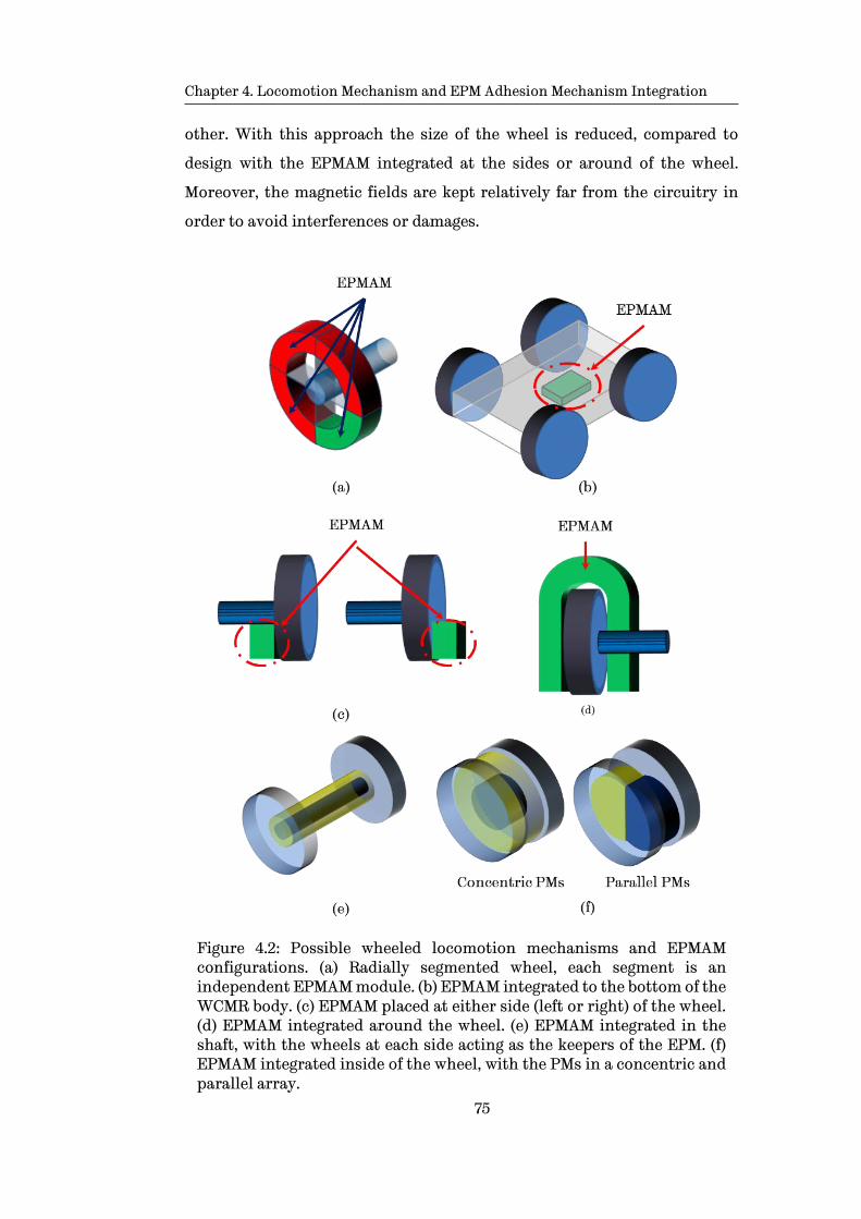
Chapter 4. Locomotion Mechanism and EPM Adhesion Mechanism Integration
75
other. With this approach the size of the wheel is reduced, compared to
design with the EPMAM integrated at the sides or around of the wheel.
Moreover, the magnetic fields are kept relatively far from the circuitry in
order to avoid interferences or damages.
Figure 4.2: Possible wheeled locomotion mechanisms and EPMAM configurations. (a) Radially segmented wheel, each segment is an independent EPMAM module. (b) EPMAM integrated to the bottom of the WCMR body. (c) EPMAM placed at either side (left or right) of the wheel. (d) EPMAM integrated around the wheel. (e) EPMAM integrated in the shaft, with the wheels at each side acting as the keepers of the EPM. (f) EPMAM integrated inside of the wheel, with the PMs in a concentric and parallel array.

Chapter 4. Locomotion Mechanism and EPM Adhesion Mechanism Integration
76
Discussion
Taking into account the advantages and disadvantages of each
combination of locomotion and adhesion mechanism, it can be stated that
there does not exist a superior configuration. The selection of the most
appropriate combination depends on the scenario and tasks that the WCMR
is intended to perform.
In terms of the present research, based in the advantages and
disadvantages for the 5 possible configurations presented, the proposed
design “4.2 Internal EPMAM” is selected as the most promising design for
wheeled WCMR with EPMAM integrated. Figure 4.3 shows a chart with the
proposed designs and in blue is highlighted the most promising design for a
WCMR for ferric structures.
In order to verify that the viability of these alternative designs
preliminary FEA simulations are perform for the cases 4.1.1, 4.1.2, 4.2.1 and
4.2.2 designs from chart in Figure 4.3.
Figure 4.3: EPMAM wheel design selection chart. Some of the possible configurations of a wheeled locomotion mechanism with an EPMAM are presented. Blue colour shows the path followed in the selection of the final EPMAM to be integrated in a wheeled locomotion mechanism.
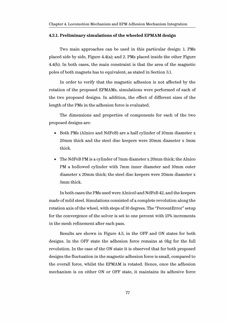
Chapter 4. Locomotion Mechanism and EPM Adhesion Mechanism Integration
77
4.2.1. Preliminary simulations of the wheeled EPMAM design
Two main approaches can be used in this particular design: 1. PMs
placed side by side, Figure 4.4(a); and 2. PMs placed inside the other Figure
4.4(b). In both cases, the main constraint is that the area of the magnetic
poles of both magnets has to equivalent, as stated in Section 3.1.
In order to verify that the magnetic adhesion is not affected by the
rotation of the proposed EPMAMs, simulations were performed of each of
the two proposed designs. In addition, the effect of different sizes of the
length of the PMs in the adhesion force is evaluated.
The dimensions and properties of components for each of the two
proposed designs are:
• Both PMs (Alnico and NdFeB) are a half cylinder of 10mm diameter x
20mm thick and the steel disc keepers were 20mm diameter x 5mm
thick.
• The NdFeB PM is a cylinder of 7mm diameter x 20mm thick; the Alnico
PM a hollowed cylinder with 7mm inner diameter and 10mm outer
diameter x 20mm thick; the steel disc keepers were 20mm diameter x
5mm thick.
In both cases the PMs used were Alnico5 and NdFeB 42, and the keepers
made of mild steel. Simulations consisted of a complete revolution along the
rotation axis of the wheel, with steps of 10 degrees. The “PercentError” setup
for the convergence of the solver is set to one percent with 15% increments
in the mesh refinement after each pass.
Results are shown in Figure 4.5, in the OFF and ON states for both
designs. In the OFF state the adhesion force remains at 0kg for the full
revolution. In the case of the ON state it is observed that for both proposed
designs the fluctuation in the magnetic adhesion force is small, compared to
the overall force, whilst the EPMAM is rotated. Hence, once the adhesion
mechanism is on either ON or OFF state, it maintains its adhesive force

Chapter 4. Locomotion Mechanism and EPM Adhesion Mechanism Integration
78
independently from the movement of the WCMR, until a different state or
adhesive force is selected.
Figure 4.4: Proposed basic concept for an EPMAM for a wheeled locomotion mechanism. (a) Both half cylinder PMs are placed parallel to each other and capped at their magnetic poles with two steel discs as keepers. (b) The NdFeB PM is place inside the Alnico PM and capped with two steel discs at the magnetic pols of the PM. In both cases the PMs are magnetized along their length.
The second characteristic that is important to validate before further
designs are explored is the effect of the length of PMs used in the EPMAM
whilst the PMs’ poles areas are kept unchanged. As mentioned in Section
3.2.3, in an EPM design the adhesive force can be maintained fixed as long as
the area of the PM’s poles remains unchanged. This means the length of the
proposed design can be increased or decreased without affecting the final
adhesive force.

Chapter 4. Locomotion Mechanism and EPM Adhesion Mechanism Integration
79
Figure 4.5: Magnetic adhesion force simulation results corresponding to the designs proposed in Figure 4.4. The graphs correspond to a full revolution from: half cylinder PMs design, blue graph; concentric PMs design, red graph. The variation in the adhesive force whilst the EPM is rotated can be considered small.
With the purpose of verifying whether this characteristic is true, a set
of simulations are performed for different lengths of the initial design,
proposed in Figure 4.4. The sizes of the EPMAM length ranges from 10mm to
30mm with increments of 2mm. The results are presented in Figure 4.6.
Figure 4.6: Effect on the adhesive force of different lengths of the EPMAM designs proposed in Figure 4.4. In both designs the influence of increasing or decreasing the length of the PMs can be considered relatively small, when compared to the maximum adhesive force.
From the simulation results presented, it was shown that the rotation
of a wheel has small fluctuations in the adhesive force, but these variations
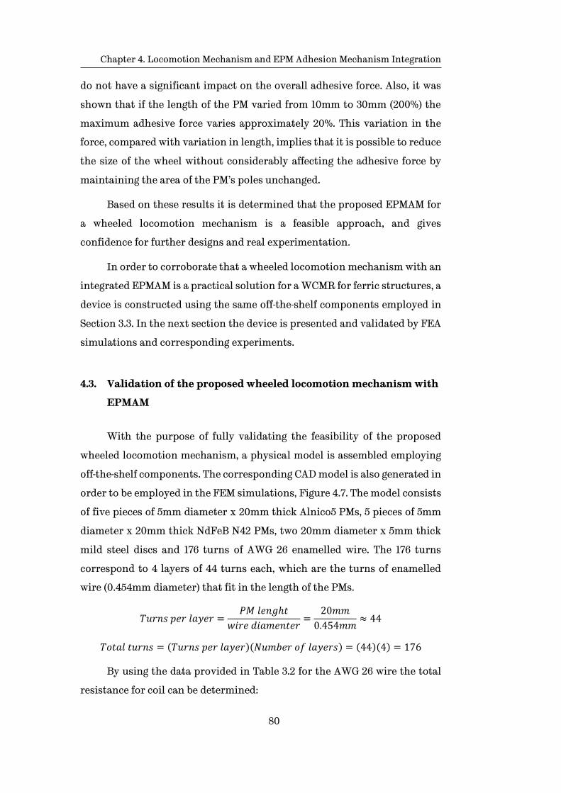
Chapter 4. Locomotion Mechanism and EPM Adhesion Mechanism Integration
80
do not have a significant impact on the overall adhesive force. Also, it was
shown that if the length of the PM varied from 10mm to 30mm (200%) the
maximum adhesive force varies approximately 20%. This variation in the
force, compared with variation in length, implies that it is possible to reduce
the size of the wheel without considerably affecting the adhesive force by
maintaining the area of the PM’s poles unchanged.
Based on these results it is determined that the proposed EPMAM for
a wheeled locomotion mechanism is a feasible approach, and gives
confidence for further designs and real experimentation.
In order to corroborate that a wheeled locomotion mechanism with an
integrated EPMAM is a practical solution for a WCMR for ferric structures, a
device is constructed using the same off-the-shelf components employed in
Section 3.3. In the next section the device is presented and validated by FEA
simulations and corresponding experiments.
4.3. Validation of the proposed wheeled locomotion mechanism with
EPMAM
With the purpose of fully validating the feasibility of the proposed
wheeled locomotion mechanism, a physical model is assembled employing
off-the-shelf components. The corresponding CAD model is also generated in
order to be employed in the FEM simulations, Figure 4.7. The model consists
of five pieces of 5mm diameter x 20mm thick Alnico5 PMs, 5 pieces of 5mm
diameter x 20mm thick NdFeB N42 PMs, two 20mm diameter x 5mm thick
mild steel discs and 176 turns of AWG 26 enamelled wire. The 176 turns
correspond to 4 layers of 44 turns each, which are the turns of enamelled
wire (0.454mm diameter) that fit in the length of the PMs.
𝑇𝑢𝑟𝑛𝑠 𝑝𝑒𝑟 𝑙𝑎𝑦𝑒𝑟 =𝑃𝑀 𝑙𝑒𝑛𝑔ℎ𝑡
𝑤𝑖𝑟𝑒 𝑑𝑖𝑎𝑚𝑒𝑛𝑡𝑒𝑟=
20𝑚𝑚
0.454𝑚𝑚≈ 44
𝑇𝑜𝑡𝑎𝑙 𝑡𝑢𝑟𝑛𝑠 = (𝑇𝑢𝑟𝑛𝑠 𝑝𝑒𝑟 𝑙𝑎𝑦𝑒𝑟)(𝑁𝑢𝑚𝑏𝑒𝑟 𝑜𝑓 𝑙𝑎𝑦𝑒𝑟𝑠) = (44)(4) = 176
By using the data provided in Table 3.2 for the AWG 26 wire the total
resistance for coil can be determined:
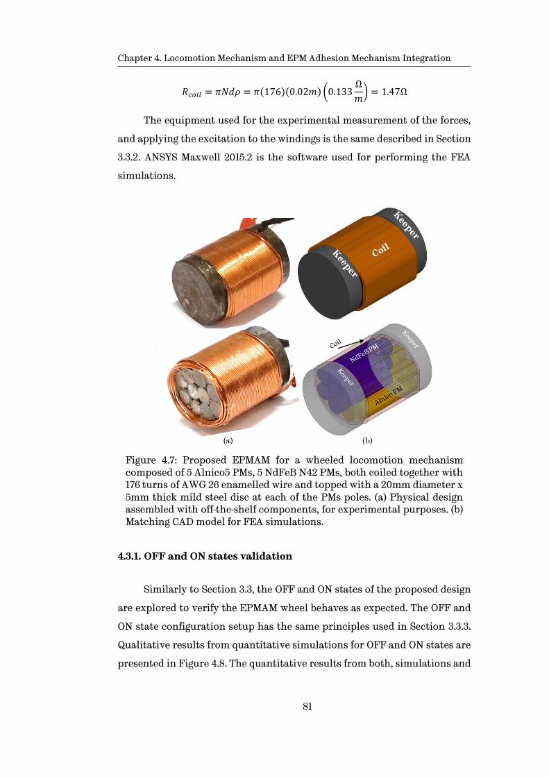
Chapter 4. Locomotion Mechanism and EPM Adhesion Mechanism Integration
81
𝑅𝑐𝑜𝑖𝑙 = 𝜋𝑁𝑑𝜌 = 𝜋(176)(0.02𝑚) (0.133Ω
𝑚) = 1.47Ω
The equipment used for the experimental measurement of the forces,
and applying the excitation to the windings is the same described in Section
3.3.2. ANSYS Maxwell 2015.2 is the software used for performing the FEA
simulations.
Figure 4.7: Proposed EPMAM for a wheeled locomotion mechanism composed of 5 Alnico5 PMs, 5 NdFeB N42 PMs, both coiled together with 176 turns of AWG 26 enamelled wire and topped with a 20mm diameter x 5mm thick mild steel disc at each of the PMs poles. (a) Physical design assembled with off-the-shelf components, for experimental purposes. (b) Matching CAD model for FEA simulations.
4.3.1. OFF and ON states validation
Similarly to Section 3.3, the OFF and ON states of the proposed design
are explored to verify the EPMAM wheel behaves as expected. The OFF and
ON state configuration setup has the same principles used in Section 3.3.3.
Qualitative results from quantitative simulations for OFF and ON states are
presented in Figure 4.8. The quantitative results from both, simulations and
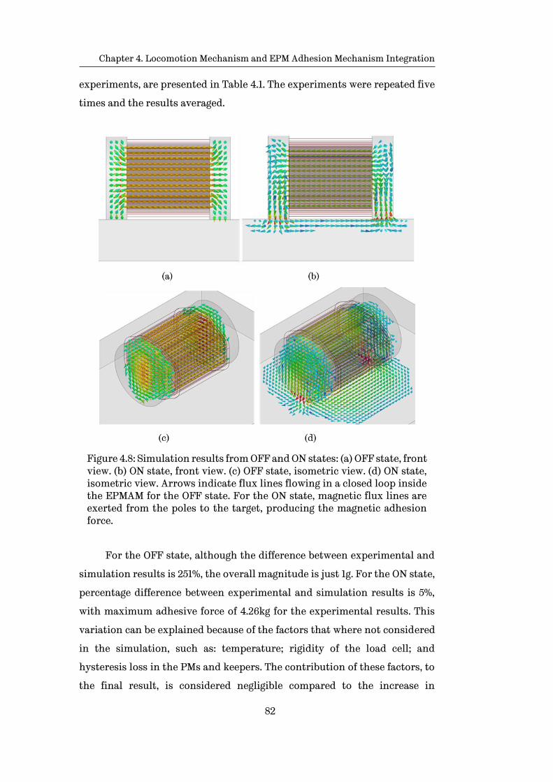
Chapter 4. Locomotion Mechanism and EPM Adhesion Mechanism Integration
82
experiments, are presented in Table 4.1. The experiments were repeated five
times and the results averaged.
Figure 4.8: Simulation results from OFF and ON states: (a) OFF state, front view. (b) ON state, front view. (c) OFF state, isometric view. (d) ON state, isometric view. Arrows indicate flux lines flowing in a closed loop inside the EPMAM for the OFF state. For the ON state, magnetic flux lines are exerted from the poles to the target, producing the magnetic adhesion force.
For the OFF state, although the difference between experimental and
simulation results is 251%, the overall magnitude is just 1g. For the ON state,
percentage difference between experimental and simulation results is 5%,
with maximum adhesive force of 4.26kg for the experimental results. This
variation can be explained because of the factors that where not considered
in the simulation, such as: temperature; rigidity of the load cell; and
hysteresis loss in the PMs and keepers. The contribution of these factors, to
the final result, is considered negligible compared to the increase in

Chapter 4. Locomotion Mechanism and EPM Adhesion Mechanism Integration
83
computational power and simulation time required if they are considered in
the initial setup.
Table 4.1: Comparison of the magnetic adhesive forces obtain through simulations and experiments for the proposed wheeled locomotion mechanism.
State Simulation Experimental Difference |%|
OFF 0.00037 kg 0.0013 kg -0.00093 kg 251
ON 4.4845 kg 4.2602 kg 0.2243 kg 5
The total weight of the EPMAM wheel is 112g, which compared to the
4.26kg of adhesive force produced, demonstrates the potential of this novel
adhesion mechanism.
4.3.2. Validation of the OFF-ON and ON-OFF switching, and variable
magnetic adhesion
In order to verify the switching performance for the OFF-ON and ON-
OFF as well as the specific adhesive for selection, similar procedures as in
Section 3.3.4 are stablished and presented next.
For the case of the transition between states a 23V pulse is applied to
the windings in order to generate the electric current needed to produce the
magnetic field in the solenoid. From eq. 3.7 is possible to determine the
current needed to produce the magnetic field intensity for demagnetizing
the Alnico 5 PM:
𝐼 =𝐻𝑐𝓵
𝑵=
(48𝑘𝐴𝑚 )(0.02𝑚)
176= 5.45𝐴
In order to ensure the demagnetisation of the Alnico 5 PM
recommended to apply magnetic field intensity three times bigger, hence the
maximum current needed is 16A.
If the total resistance of the solenoid is 1.47Ω, by using the ohms law
the voltage can be depicted:

Chapter 4. Locomotion Mechanism and EPM Adhesion Mechanism Integration
84
𝑉 = 𝐼𝑅 = (16𝐴)(1.47Ω) = 23.52𝑉
An incremental electric pulse is applied starting from 0.3ms until
saturation of the Alnico 5 PM is reached. Once the Alnico5 PM reaches
saturation no more final adhesive force, for the ON state, will be obtained.
Similarly, for the OFF state, once Alnico5 PM reach saturation the final
adhesive force is zero.
Results from simulations are presented in Figure 4.9(a) where it is
observed that by increasing the length of the pulse the final adhesive force
increases in a monotonic way. After the system reaches saturation, 2.0ms in
this case, no increase in the magnetic force is generated. The maximum
adhesive force for this design is 4.4845kg.
Correspondingly, the experimental results in Figure 4.9(b) have a
comparable increasing behaviour, in a qualitative way, compared with the
simulations. As it was mentioned in Section 3.3.4, several factors are
involved in the experiments that were not considered in the simulations, to
reduce computational and simulation time. These factors are: the spring
behaviour of the load cell; the rigidity of the test bench (which also
introduces transient oscillation when a pull is produced by the EPM on the
load cell); and, temperature.
These factors introduce transient effects in the response behaviour of
the experiments, which are present as oscillations in the measured data. In
other to show the final state of the measurement after the transient effects
have settle, a longer period of time (100ms) is presented in Figure 4.9(c).
From simulation results it is observed that for this particular design
saturation is reached with an electric pulse of 2.0ms, Figure 4.9(a). As
discussed in Section 3.3.4, longer pulses do not generate bigger final adhesive
forces. On the contrary, pulses longer than 2.0ms only produce bigger peak
adhesive force, whilst applied, and generate a temperature rise in the EPM
due to the extra magnetic field generated. In the case of the experimental
results it is observed that saturation is reach with a 4.5ms pulse, Figure 4.9(b)
and (c).

Chapter 4. Locomotion Mechanism and EPM Adhesion Mechanism Integration
85
Figure 4.9: Final adhesive force vs increasing pulse lengths. (a) Simulation results, saturation is reached with 2.0ms pulse width. (b) Experiment results, saturation reached with a 4.5ms pulse width. (c) Experimental results presented for an extended period of time to show final magnetic force values after the transient effects of the load cell, test bench and holding components have settle down.
(a)
(b)
(c)

Chapter 4. Locomotion Mechanism and EPM Adhesion Mechanism Integration
86
By comparing the simulation and experimental results, it is observed
that the time to achieve the saturation in the experiment is approximately
twice that for simulations. The reasons for this discrepancy are the factors
not included in the simulations due to computational and simulation times.
These factors have an impact in the final magnitude of the solenoid
inductance, which determines how fast the current flowing through the
windings reaches the maximum value.
To better appreciate how the force increases with the length of the
pulse applied to the windings for the OFF-ON switching, in Figure 4.10 a
comparison of the simulation and experimental data is presented.
The force values plotted correspond to the final value of the adhesive
force, long after all the transient effects have settled. This final adhesive
force value is obtained by taking the mean of the final 1.0ms for the case of
the simulations data. For the case of the experimental measurements, the
final 20ms from the data are taken and the mean is obtained, for minimizing
the impact of the noise present in the measurements.
From the results obtained from both, experiments and simulations, a
big discrepancy is observed regarding the length of the electrical pulse
needed to reach maximum final adhesive force (≈ 100%). This percent error
may be enough to dismiss the EPM switching behaviour in a quantitative
way. However, from the qualitative point of view both, experimental and
simulation results present similar behaviours, they increase proportionally
to the length of the electrical pulse applied, both reach comparable
maximum adhesive force once the PM are driven to saturation. Furthermore,
taking into account the time scale (ms), experimental results prove the
viability of the EPMAM, because it only takes a few milliseconds to perform
the switching.

Chapter 4. Locomotion Mechanism and EPM Adhesion Mechanism Integration
87
Figure 4.10: Comparison of magnetic force from experiments and simulation for increasing pulse lengths. Blue line represents the simulation results and red line the corresponding experimental results. The time for reaching the maximum force in the experiments is approximately three times the time obtained in simulations. This difference is due to factors that were not taken into account in the simulations, which have an effect in the inductance of the solenoid.
However, if the length of pulse needed to reach the maximum adhesive
force, for a specific design, turns out to be significantly long, there ways exist
to reduce this time:
• Increasing the voltage applied to the windings. As discussed in
Section 3.1.1, a coil with a fixed number of turns has a defined
resistance, if the voltage applied to the coil is increased the current
flowing through the coil increases proportionally. However, increasing
the magnitude of voltage is limited by the maximum voltage supported
by the circuitry needed to control this voltage, as well as the capacity
of the batteries. In both cases a high voltage reduces the time of the
switching, however, the cost of the related circuitry and batteries can
make it unpractical.
• Reducing the resistance of the coil: By reducing the resistance of the
coil, the maximum current due to a fixed voltage is increased. One way
to reduce the resistance of a solenoid is by increasing the diameter of
the enamelled wire used in the solenoid and keeping the magnitude of
the applied voltage fixed. The only constraint in this case is the size of
the final EPM.

Chapter 4. Locomotion Mechanism and EPM Adhesion Mechanism Integration
88
• Reducing the coil inductance: Another way is reducing the self-
inductance the coil. By dividing a single coil into several different ones,
while keeping the original number of turns among the coils, and
connecting those coils in parallel, it is possible to reduce the total self-
inductance. If two or more inductors are connected in parallel the
equivalent inductance is less than any of the inductors connected in
parallel, Eq. 4.1.
LT =1
1
L1+
1
L2+⋯
1
Ln
(4.1)
For this particular case, the motor driver used for controlling the
switching has a maximum input voltage of 30V. Also, the available enamelled
wire at that moment was an AWG 26 wire with 0.454mm diameter. For these
reasons, it was chosen to split the coil in order to verify that it is possible to
reduce the time to reach the maximum adhesive force by dividing the
original coil, into two coils and connecting them in parallel. Experimental
results are presented in Figure 4.11.
The experimental results show that, by splitting the original coil into
two or more coils, it is possible to reduce the time for reaching the maximum
final adhesive force without changing the input voltage, or gauge of the
enamelled wired. The only condition is to keep the number turns of the
original coil.
Figure 4.11: Comparison of the experimental results from the EPMAM wheel for both cases: 1. a single 176 turns coil, blue graph; and 2. coil split in two parallel coils of 88 turns each, red graph. By dividing the coil of the

Chapter 4. Locomotion Mechanism and EPM Adhesion Mechanism Integration
89
EPM into two branches the time to reach the maximum adhesive force is reduced approximately four times.
Experimental and simulation results, performed with the initial wheel
design with an EPMAM, have shown that such adhesion mechanism is
feasible and has potential in the field of climbing robots for ferric structures.
A particular condition that must be taken into account in the design of
any magnetic adhesion mechanism is the effect of air gaps or any non-ferric
material between the EPMAM and the steel structure. Magnetic force decays
in an exponential way, which means that in the presence of a small non-ferric
obstacle, a thick coating or even corrosion, the adhesive force can be
adversely impacted.
With the purpose of defining how the presence of an air gap or a non-
ferric object impacts the adhesive force, the preliminary EPMAM wheel
design is used in a set of FEA simulations and experiments. These consist on
setting different air gaps (from 0.1mm to 3mm, with 0.1mm increments).
Results from both, experiments and simulations, are presented in Figure
4.12.
Figure 4.12: Adhesive force vs increasing gap, between EPMAM device and ferric surface. Red line corresponds to simulation data and blue line to experimental data. For both cases the magnetic adhesive force is reduced by 75% after 1.5mm.

Chapter 4. Locomotion Mechanism and EPM Adhesion Mechanism Integration
90
For the particular case of the device proposed in Figure 4.7, simulation
and experimental results show that the magnetic adhesive force decreases
to approximately 75% with a 1.5mm gap. Although this side effect is the same
for all magnetic adhesive mechanism, the particular capability of the EPMs
of varying their adhesive force allows to design a stronger EPMAM to
overcome this limitation, up to some degree.
4.4. Concluding remarks
In the present chapter, the main potential locomotion mechanisms
were presented and the feasibility of being implemented in a WCMR was
explored. A set of specific requirements, for the final WCMR, were
established in order to allow the performance of certain tasks for a specific
scenario. Based on the requirements, the wheeled locomotion mechanism
was selected as the most appropriate for the inspection of large ferric
structures. Next, possible configurations of the selected wheeled locomotion
mechanism and the EPMAM were investigated, and the most suitable was
chosen. Having selected the most suitable wheel-EPMAM combination a
preliminary design was built, using off-the-shelf components.
Correspondingly, a CAD model was drawn (for simulation purposes) with the
aim to validate the viability of the design.
The validation of the design consisted of simulations and experiments
for the OFF and ON states, the specific selection on a particular adhesive
force value, and the impact of the presence of an air gap. Additionally, the
possibility of reducing the total self-inductance of coil was proposed. It was
suggested that by splitting the in two or more coil branches, without
modifying the original number of turns, it was possible to reduce the time
for reaching the maximum adhesive force. Results from the corresponding
experiment demonstrated that it is a viable strategy.
The results obtained from the validation of the wheel-EPMAM design
confirmed its feasibility and the potential for its use as a novel adhesion
mechanism to be implemented in WCMR for ferric structures.
Chapter 4. Locomotion Mechanism and EPM Adhesion Mechanism Integration
91
Starting from the results obtained in the present chapter, a more
detailed analysis of the initial wheel-EPMAM design is presented in the next
chapter and the most critical factors for the performance of adhesion
mechanism are explored in detail.
Chapter 4. Locomotion Mechanism and EPM Adhesion Mechanism Integration
92

93
Chapter 5
EPM Wheel Design
In Chapter 4 the most suitable locomotion mechanism, to be
implemented in a WCMR for ferromagnetic structures, was explored. From
the main locomotion mechanisms, wheeled locomotion was elected as the
best option based on the predefined requisites. Next, different potential
configurations for the integration of the locomotion mechanism and
EPMAM were presented. Based on the advantages and disadvantages, for the
specific scenario of performing over large ferromagnetic structures, each of
the suggested configurations were examined and the most promising
configuration was selected. In order to validate the chosen configuration a
wheel EPM device was constructed, using off-the-shelf components.
Additionally, a set of experiments and FEA simulations were presented.
Finally, results from simulations and experiments showed that the proposed
wheeled-EPMAM configuration is feasible.
In the present chapter the proposed wheeled-EPMAM configuration is
examined in more detail using customised components in order to
determine their impact on the performance of the EPMAM. The relevant
parameters of each component is determined and varied to determine its
influence in the final adhesive force. The final EPMAM wheel is intend to be
implemented in an existing MR, which uses wheels with a diameter of 7cm.

Chapter 5. EPM Wheel Design
94
Section 5.1 explores the influence of different magnitudes for the
thickness of the steel keepers, the gauge of the enamelled wire and the
presence of an air gap, and the most suitable is selected. Next, in Section 5.2
two configurations for the implementation of the EPMAM in an actual wheel
are explored and the best is selected. In Section 5.3 a wheel design, using the
customised selected components is proposed based on the cost and the
manufacturability the components. Section 5.4 presents the final EPMAM
device built with the customised components selected in the previous
section and a set of simulations and experiments are presented in order to
validate performance of the EPMAM. Finally, Section 5.6 presents the
concluding remarks of the chapter.
Figure 5.1: EPM wheel design using customised components. The design consists of two parallel PMs both coiled with enamelled wire and capped with two steel keepers.
5.1. Influence of the individual design components in the final
adhesive force
In an EPM wheel, each component is contributes, to the optimum
performance of the final device. With the purpose of determining the

Chapter 5. EPM Wheel Design
95
influence of the main components, in addition to define the most
appropriate size for a specific design, they are individually examined in the
next sections. An initial design using customised components, that are
feasible to be manufactured, is explored, Figure 5.1. The design consist of two
parallel PMs (Alnico5 and NdFeB N48) both coiled with enamelled wire and
caped with two steel keepers, with the same configuration of the design
examined in Section 4.3.
In order to determine the impact of each of the components, FEA
simulations are performed using different values of characteristic
parameters, such as diameters and wire gauge, whilst keeping the rest
unchanged. The setup for each simulation and the corresponding results are
presented below. Section 5.1.1 examines the influence of the steel keepers’
size on the magnetic adhesive force. In Section 5.1.2, the effect of different
enamelled wire gauges, in the EPM wheel adhesion performance, is explored.
Finally, Section 5.1.3 explores the impact of an air gap, or any non-ferric
material, between the EPM wheel and the surface on which it is adhered.
5.1.1. Steel keepers
The size of the steel keepers is important, since they are the path to
redirect and focus the magnetic flux lines to a specific target. Small keepers
saturate with low magnetic field densities, thus the just a small part of the
magnetic field lines is focused to the specific area where the magnetic
attraction is needed. On the other hand, although big keepers, are capable of
taking the magnetic flux lines without saturation, might become too heavy.
Thus, reducing the maximum net adhesive force.
Keeper thickness
With the aim of defining how the maximum adhesive force is affected
by the thickness of the steel keepers, FEA simulations are performed for
different thicknesses. From the design shown in Figure 5.1, the thickness,
along the rotation axis, is increased in the range from 2.5mm to 20mm, with

Chapter 5. EPM Wheel Design
96
1mm increments. In Figure 5.2 the initial (2.5mm), intermediate (10mm) and
final (20mm) models are presented.
Results from the FEA simulations for the different steel keepers’
thicknesses are presented in Figure 5.3. It can be observed that increasing
the thickness of the keepers increases the maximum adhesive force. This is
due to the increasing volume that can contain more magnetic flux lines.
Figure 5.2: EPM wheel designs for different steel keepers’ thickness. (a) Initial 2.5mm thickness. (b) Intermediate 10mm thickness. (c) Maximum 20mm thickness.
Figure 5.3: Force vs steel keepers’ thickness. The adhesive force is increased with increasing keepers’ thickness.
In order to select the most suitable keeper other factors must be
considered, such as the final size of the wheel and weight. For the specific
design of a wheel with a diameter of 70mm and ≈70mm in thickness, the
10mm keeper is selected. A thicker keeper, increases the final wheel size and
weight beyond acceptable limits. For instance, a 15mm thick keeper
Chapter 5. EPM Wheel Design
97
increases in 50% its size and weight, however its maximum possible adhesive
force is increased by only 12.76%.
5.1.2. Enamelled wire gauge
A crucial part in the design of an EPM is the appropriate selection of
the enamelled wire gauge. As mentioned in Section 3.3.1, diameter, resistance
and weight depend on the wire gauge. A small wire gauge number indicates
a low resistance, and a large diameter, inversely, bigger wire gauges refer to
a wire with higher resistance, and smaller diameter. Table 3.2 shows the
seven wire gauges considered for the proposed EPM wheel design.
With the purpose of exploring the influence of each wire gauge, the
design presented in Figure 5.1 is simulated for each of the wire gauge of Table
3.2. Simulations are performed for a 0 - 60v range for each of the wire gauges
in order to determine the how the final adhesive force is influenced. Results
are presented in Figure 5.4.
Results show that, in order to achieve the maximum possible adhesive
force, bigger voltages are needed for enamelled wires with smaller resistance.
In order to select the most suitable wire gauge the three main factors,
presented in Table 3.2, must be considered. Bigger wire gauges have smaller
diameters and are lighter. However, their resistance increases, which means
that only smaller electric currents are allowed to flow through the wire.
Consequently, the external magnetic field generated by the solenoid will not
have the sufficient strength to fully magnetise and demagnetise the Alnico
PM.
On the other hand, smaller wire gauges have lower resistances that
allow bigger electric currents. Hence, bigger magnetic fields can be produced
when used in a solenoid. However, as seen in Table 3.2, the size and weight
increases considerably, which means a bigger and heavier solenoid. Based on
the FEA simulation results, from the seven proposed enamelled wire gauges.
Additionally taking into account the maximum voltage allowed by the motor

Chapter 5. EPM Wheel Design
98
driver (30v), which is going to control the direction and length of the electric
pulse, AWG 26 is selected as the most feasible.
Figure 5.4: Force vs voltage for each of the enamelled wire gauges presented in Table 3.2. (a) No gap between EPM wheel and target steel plate. (b) 2.5mm gap between EPM wheel and target plate. It is observed that as the resistance of the wire increases, the voltage needed to achieve the maximum possible adhesive force increases.
5.1.3. Gap between EPM device and adhesion surface
Another crucial part in the design of any magnetic adhesion
mechanism is the impact of an air gap, or any non-ferric material, between
Chapter 5. EPM Wheel Design
99
the adhesion mechanism and the surface where it is adhered. Gaps must be
considered, because in most of the situations there are factors that will not
allow direct contact between the device and the surface. Things like
corrosion, steel coatings, grease or dirt are some of the most common factors
that do not allow a direct contact. Therefore, the maximum possible
adhesive force is not achieved in most of the cases.
With the purpose of examining this effect, an increasing air gap
between the proposed design and the target steel plate gas simulated, Figure
5.5. The initial magnitude of the gap is 0mm, and is increased in 0.01mm
intervals, up to 5.0mm. Results from the corresponding FEA simulation are
presented in Figure 5.6.
Figure 5.5: Gap between EPM wheel device and target steel plate.
FEA simulations results show that the magnetic adhesive force
decreases dramatically with small gaps. For this design, although the initial
magnetic adhesion can be considered high (24.58kg), it decreases in 90%, to
3.12kg with a 1.0mm air gap between the EPM wheel and the target (steel
plate).
Furthermore, in order to get a better understanding of the influence of
an air gap, a set of simulations are presented in Figure 5.7. In these FEA
simulations, the presence of different gaps for each of the keeper’s thickness,
examined in Section 5.1.1, are explored in Figure 5.7.
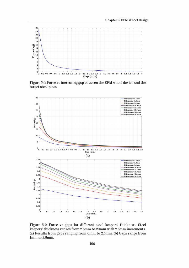
Chapter 5. EPM Wheel Design
100
Figure 5.6: Force vs increasing gap between the EPM wheel device and the target steel plate.
Figure 5.7: Force vs gaps for different steel keepers’ thickness. Steel keepers’ thickness ranges from 2.5mm to 20mm with 2.5mm increments. (a) Results from gaps ranging from 0mm to 2.5mm. (b) Gaps range from 1mm to 2.5mm.

Chapter 5. EPM Wheel Design
101
Additionally, FEA simulations are performed exploring the influence
of the keepers’ thickness for different air gaps. Results are presented in
Figure 5.8. It can be observed that the main factor that impacts the final
adhesive force, is the length of the gap for keepers with thickness greater
than 10mm. From this results, also it is verified that a 10mm thick keeper is
the most appropriate for the case of the present design.
Figure 5.8: Force vs thickness for air gaps, ranging from 0mm to 2.5mm. These results confirm that the 10mm thick keeper is the appropriate selection for the proposed design.
5.2. Configuration of the EPMAM into the wheel
An important consideration on the integration of the EPMAM and the
wheel design is how the electric pulse is going to be supplied to the EPMAM
as the wheel rotates. Two possible solutions for this configuration are
discussed next, in order to select the most appropriate method of supplying
the power energy to the solenoid windings.
5.2.1. Rotating EPMAM
On possible solution is to fully integrate the EPMAM with the wheel, or
let the EPMAM be the wheel itself. For this configuration the electric pulse
needs to be supplied, from the static MR frame to the rotating wheel, with
the help of carbon brushes. However, carbon brushes have several
disadvantages when employed in small devices:
Chapter 5. EPM Wheel Design
102
• Contact resistance is high.
• Considerable voltage drop.
• Production of sparks, which can be potentially dangerous in some
scenarios.
• Brush holders and commutators are needed, resulting in a bigger
wheel size.
• Required to be replaced once the useful life is reached, or get
damaged.
5.2.2. Static EPMAM
An alternative solution is to maintain the EPMAM fixed, with respect
to the MR frame, and using gears and bearings to allow the rotation of the
wheel. The main advantage of this approach is that the can be connected
directly to the power source. Additionally, by maintaining the EPMAM fixed
the volume of the keepers can be reduced. Considering results from FEA
simulations, shown in Figure 5.9, it can be observed that the upper part and
outer region of the keeps, do not contribute to concentring the magnetic flux
lines. On the contrary, these areas disperse the magnetic flux and add dead
weight to the final device. Eliminating these portions of the keepers’ results
in the design shown in Figure 5.10.
Results from the corresponding FEA simulations for the optimized
design, Figure 5.10, are presented in Figure 5.11. It is observed that magnetic
flux is more evenly distributed throughout the keepers’ volume.
Furthermore, the quantitative results show that the maximum possible
adhesive force is increased in by 55% from 25.1kg to 38.76kg. The reason for
the increase in the adhesive force is that the magnetic flux lines, which were
dispersed in the first design, are now concentrated and focused to the target
plate by the optimized shape of the keepers. This denser and concentrated
magnetic flux produces a stronger magnetic adhesive force.

Chapter 5. EPM Wheel Design
103
Figure 5.9: Concentration of the magnetic flux inside of the keepers, for the case of a rotating EPMAM design. Areas within the red dashed lines show the portions of the keepers that reduce the efficiency of the EPAM by dispersing the magnetic flux and adding dead weight. (a) Front view. (b) Side view. (c) Isometric view.
Figure 5.10: EPMAM with optimized steel keepers for the case of a fixed EPMAM – wheel configuration. The portions that reduce the efficiency of the EPMAM from the previous design, Figure 5.9, are removed. (a) Front view. (b) Isometric view.
Figure 5.11: Concentration of the magnetic flux inside of the keepers, for the case of the improved EPMAM design. By removing the portions of the original design, which dispersed the magnetic flux, a denser and focused magnetic field is generated. (a) Front view. (b) Side view. (c) Isometric view.

Chapter 5. EPM Wheel Design
104
5.3. Customised EPMAM design for manufacturing purposes
Based on the advantages and disadvantages of the both, rotating and
static approaches, and taking into account the results from the FEA
simulations, the static EPMAM configurations is selected. The assembly for
the EPM wheel with EPMAM is presented in Figure 5.12. The fixed EPMAM
and the rotating outer part of the wheel are connected using bearings.
Figure 5.12: Wheel design with a static EPMAM for manufacturing purposes. (a) Isometric view. (b) Exploded view, for showing the internal components of the EPMAM.
5.3.1. Manufacturability of the EPMAM components
In order to build the customised EPM wheel different companies have
been consulted, to assess whether the manufacturing of the components is
feasible, in addition to the costs. All of them agree that the manufacturability
of the internal EPMAM components is feasible, however the costs are
increased by the presence of round elements and chamfer cuts
manufacturing times are also heightened.
In the case of the PMs, the simplest design a half cylinder shape, with
magnetisation along the thickness is chosen. Although, initially different
shapes and magnetisations were considered, the manufacturing cost of the
quantities need was out of the current budget. For this reason, the initial
design was chosen to be manufactured.

Chapter 5. EPM Wheel Design
105
For the case of the steel keepers the cost for manufacturing the design
presented in Figure 5.10 and Figure 5.11, was also out of budget. For this
reason a simplified design is used for the keepers shape, Figure 5.13.
Figure 5.13: Final EPMAM customised components including a simplified keepers’ design.
In the case of the windings around the Alnico5 PM, the 480 turns are
distributed in eight layers of 60 turns each. As shown in Table 3.2, AWG 26
enamelled wire has a resistance of 0.133mΩ/m, which results in 3.9Ω for the
480 turns around the Alnico PM. The magnitude of the resulting resistance
along with the 23V supplied by the LiPo battery only produced a 5.89A
current. This current was not enough to re-magnetise the Alnico5 PM.
However, as discussed in Section 4.3.2, it is possible to reduce the total
inductance and resistance of a fixed number of turns in a coil by splitting the
number turns into branches. For this particular case, the 480 turns, are split
into 4 branches of two layers of 60 turns, in each layer. By doing this, the
total resistance is reduced to 0.256Ω.
With the purpose of verifying the performance of the EPMAM shown
in Figure 5.13, FEA simulations are performed. Results are presented in
Figure 5.14 for two scenarios: 1. Gap=0mm; and 2. Gap=2.5mm.
From the results, it is observed that the maximum possible adhesive
force is reached with a 50A current. Additionally, it is observed that the
maximum adhesive force is 21.72kg and 7.22kg for the 0mm and 2.5mm gaps,
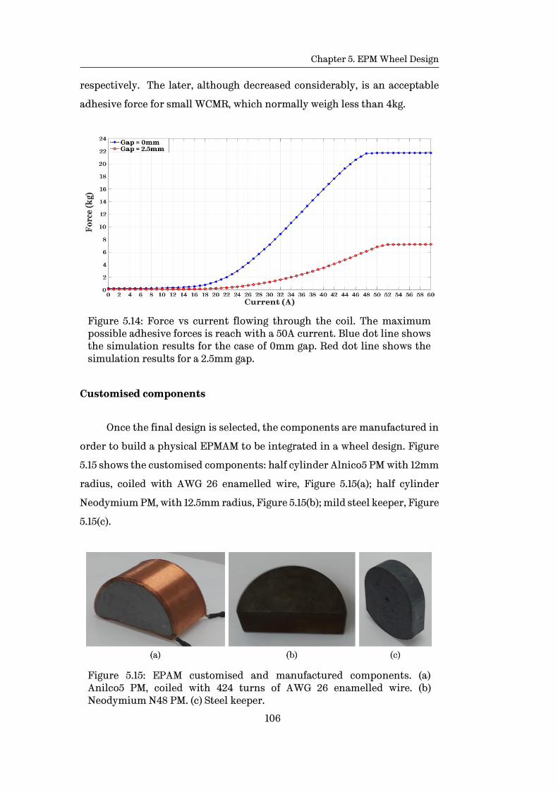
Chapter 5. EPM Wheel Design
106
respectively. The later, although decreased considerably, is an acceptable
adhesive force for small WCMR, which normally weigh less than 4kg.
Figure 5.14: Force vs current flowing through the coil. The maximum possible adhesive forces is reach with a 50A current. Blue dot line shows the simulation results for the case of 0mm gap. Red dot line shows the simulation results for a 2.5mm gap.
Customised components
Once the final design is selected, the components are manufactured in
order to build a physical EPMAM to be integrated in a wheel design. Figure
5.15 shows the customised components: half cylinder Alnico5 PM with 12mm
radius, coiled with AWG 26 enamelled wire, Figure 5.15(a); half cylinder
Neodymium PM, with 12.5mm radius, Figure 5.15(b); mild steel keeper, Figure
5.15(c).
Figure 5.15: EPAM customised and manufactured components. (a) Anilco5 PM, coiled with 424 turns of AWG 26 enamelled wire. (b) Neodymium N48 PM. (c) Steel keeper.

Chapter 5. EPM Wheel Design
107
Once the EPMAM components are manufactured and the windings around the
Alnico5 coiled, the actual EPMAM is built and the corresponding CAD model drawn
Figure 5.16.
Figure 5.16: EPMAM device built with customasied components. Physical design (a) front view and (b) isometric view. CAD model (c) front view and (d) isometric view.
5.4. Simulation and experimental results from the customised
EPMAM
After the EPMAM device is built, the next step is to validate the FEA
simulation results presented in Figure 5.14. Using the equipment and setup
presented in Section 3.3.2, the corresponding experiments are performed in
order to measure the adhesive force produced by applying different electric
pulses. Results from the experiments are presented in Figure 5.17 and Figure
5.18.

Chapter 5. EPM Wheel Design
108
Figure 5.17: Experimental results from different electric pulses. Graphs presented correspond to the resulting OFF-ON transition for different electric pulse lenghts.
For the case of the OFF-ON switching different pulse lengths are
applied to the windings. The transient response, shown in Figure 5.1,
presents a similar behaviour to the discussed in Section 3.3.4. From these
results is observed that the maximum adhesive force is reached with 15ms
electric pulse.
Figure 5.18: Force vs current obtained by experimental mesaurments. Blue dot line shows the experimental mesaurments for the case of 0mm gap. Red dot line shows the experimental mesaurments for a 2.5mm gap.
Figure 5.18 presents the results from an increasing electric pulse that
range from 0 to 20ms, after the initial transient effects from the pulse have
settled. After comparing the results from the simulations presented in

Chapter 5. EPM Wheel Design
109
Figure 5.14 with the experimental results, a big discrepancy in the maximum
possible adhesive forces is observed.
Table 5.1: Comparison of simulation and experimental results for the customised EPMAM.
Gap Simulation results (kg)
Experimental results (kg)
Difference %
0 mm 21.72 6.12 255
2.5 mm 7.22 1.56 363
Although experimental measurements show a considerable deviation
from the simulation results, which might dismiss the feasibility of the
proposed EPMAM, a search for possible causes is performed.
Due to the higher magnetic fields produced by bigger PMs and stronger
solenoid, compared to the ones employed for the concept validation in
Chapters 3 and 4, the non-linear magnetic characteristics of the EPMAM
components must be taken into account. It is found out that a stronger
magnetic field drives the mild steel of the keepers to saturation, which did
not happen in the concept validation experiments.
Moreover, magnetic characterises of mild structural steel vary
considerably from the chemical composition of each steel type. When
produced for structural purposes, mild steel is not magnetically
characterised when fabricated. However, MagWeb6 produce the magnetic BH
curves for different types of steel. After analysing the mild steel BH curve
data provided by MagWeb, and the generic BH curve from ANSYS Maxwell, a
difference is observed. The mild steel saturation points from MagWeb and
Maxwell are 2.085Teslas and 1.72Teslas respectably. A lower magnetic BH
saturation point means a lower magnetic flux flowing through the material
after reaching saturation.
6 http://magweb.us/free-bh-curves/

Chapter 5. EPM Wheel Design
110
Additionally, in order to obtain a more accurate simulation, the actual
BH curve for the PM were requested to Arnold Magnetic Technologies7,
which is the manufacturer of the PM. Using the data from the more accurate
magnetic BH curves for the components of the EPMAM simulations are
performed again. Results are presented in Figure 5.19 and a comparison is
presented in Table 5.2. The experiments were repeated five times and the
results averaged.
Figure 5.19: Force vs current flowing through the coil, with magnetising BH curves obtained from manufacturers. The maximum possible adhesive forces is reach with a 50A current. Blue dot line shows the simulation results for the case of 0mm gap. Red dot line shows the simulation results for a 2.5mm gap.
Table 5.2: Comparison of simulation and experimental results for the customised EPMAM with magnetising BH data from manufacturers.
Gap Simulation results (kg)
Experimental results (kg)
Difference %
0 mm 12.16 6.12 99
2.5 mm 4.53 1.56 190
7 http://www.arnoldmagnetics.com/en-us/

Chapter 5. EPM Wheel Design
111
Results from FEA simulation, performed with magnetising BH curves
obtained from the PMs and mild steel manufacturers, show a more realistic
behaviour of the EPMAM performance. Qualitative results exhibit a similar
behaviour between simulation and experimental results. However, in terms
of the quantitative results still there exist a significant deviation between
the FEA simulation and experimental results. There are several factors that
affect the outcomes from experiments that were not considered in the
simulations setup, which could be answer for this discrepancy. These factors
are:
• Environmental variables: Temperature and humidity, which can
reduce the saturation points, specifically in the regular neodymium
magnets. These magnets are sensitive to changes in temperature.
• Painting coating: Coating on the steel plate used as target where the
EPMAM was adhered. Paintings, coatings and even small corrosion
affect the magnetic properties of the steel.
• Load cell and test bench: As discussed in Section 3.3.4 the load cell
used for measuring the pulling of the EPMAM when the adhesion was
ON has a spring transient behaviour. This created oscillations along
the measurement axis (up and down), which although lasted
approximately 1ms could have affected the initial gap. Hence affecting
the measurement of the force.
These factors might not have big impact in the outcomes if considered
individually, however when combined could a considerable influence in the
results. Another thing to considered is the accuracy of FEA software, which
only allow to perform a relative performance comparison, specially when
demagnetization process is involved
Overall, experimental results still demonstrate the feasibility of the
proposed novel adhesion mechanism, which can be further enhance by
exploring use of alternative materials with higher magnetic saturation
points. As well as further optimization of the components.

Chapter 5. EPM Wheel Design
112
5.4.1. Discussion
Results from the FEA simulations and experiments, although
presented a similar qualitative behaviour, showed significant discrepancies
in terms of the quantitative results. After analysing the possible causes for
the differences, it was determined that magnetising BH curves used initially
were generic, which caused the simulation results to be inaccurate.
As a result, the actual BH curves, provided by the manufacturers of the
PMs and mild steel were used to perform the simulations, again. Quantitative
results, although exhibit a more realistic outcome, still had a significant
difference form the once obtained on the experiments. As result the most
probable reasons for the discrepancies between experimental and
simulations were presented.
Finally, despite the differences between simulations and experiments,
the EPMAM was considered feasible and potential based on the experimental
results. Even though the adhesive forces from the real device were
significantly smaller compared to the obtained in simulations, these forces
still are strong enough to maintain the EPMAM wheel design attached to a
vertical ferric structure. Furthermore, the EPMAM has the enough strength
to hold its own weight and the weight of a MR, in which it is implemented.
In the next section the final EPM wheel prototype is presented. The
prototype is built to fit an off-the-shelf MR.
5.5. EPMAM Integration into a Functional Wheel Design
In the present section, the EPMAM device built in Section 5.3.1 is
integrated into a functional wheel design with the purpose to be
implemented in an off-the-shelf MR. The EPMAM is set at the core of the
wheel in a fix position with respect to the main frame of the MR. To allow the
rotation of the wheel a customised bearing and a planetary gear were
integrated to the design as it can be seen in Figure 5.22. Both, the gear and
bearing, are non-ferric 3D-printed components in order to not interfere with
the performance of the adhesion mechanism.

Chapter 5. EPM Wheel Design
113
5.5.1. Wheel design with an internal fixed EPMAM
The final wheel complementary components are integrated in order to
allow the rotation of the wheel whilst keeping the EPMAM in a fixed position,
Figure 5.20 presents the wheel design with the EPMAM as fixed core. Figure
5.21 shows the interaction of the internal EPMAM for both OFF and ON
states.
Figure 5.20: Wheel desing with a fixed EPMAM as core of the wheel.
Figure 5.21: Magnetic field interaction for the OFF and ON states, inside the EPM wheel. (a) Front view for the OFF state. (b) Front view for the ON state. (c) Isometric view for the OFF state. (d) Isometric view for the ON state.

Chapter 5. EPM Wheel Design
114
For the case of the rest of the wheel components, apart from the
EPMAM, must be fabricated with non-ferric materials to avoid interferences
between them and the magnetic fields produced by adhesion mechanism.
Figure 5.22 presents the final CAD design for the final prototype, with an
exploded view of all internal components.
Figure 5.22: Final wheel design to be implemented in a of-the-shelf MR. (a) Isometric view of the full wheel. (b) Isometric view of the internal components of the wheel. (c) Exploded view of all the internal components of the wheel.
All the components of the wheel prototype, apart from EPMAM, are
customised 3D printed plastic components. The final assembled EPM wheel
using these components is presented in Figure 5.23.
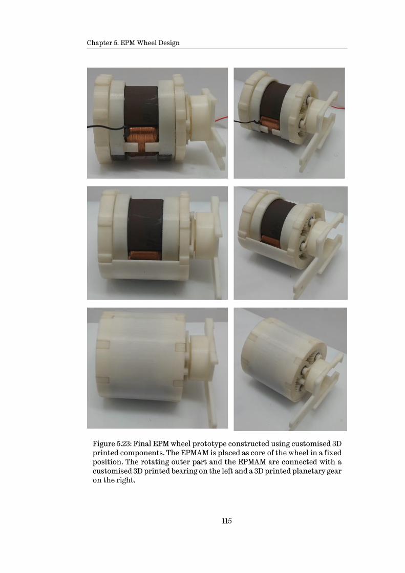
Chapter 5. EPM Wheel Design
115
Figure 5.23: Final EPM wheel prototype constructed using customised 3D printed components. The EPMAM is placed as core of the wheel in a fixed position. The rotating outer part and the EPMAM are connected with a customised 3D printed bearing on the left and a 3D printed planetary gear on the right.
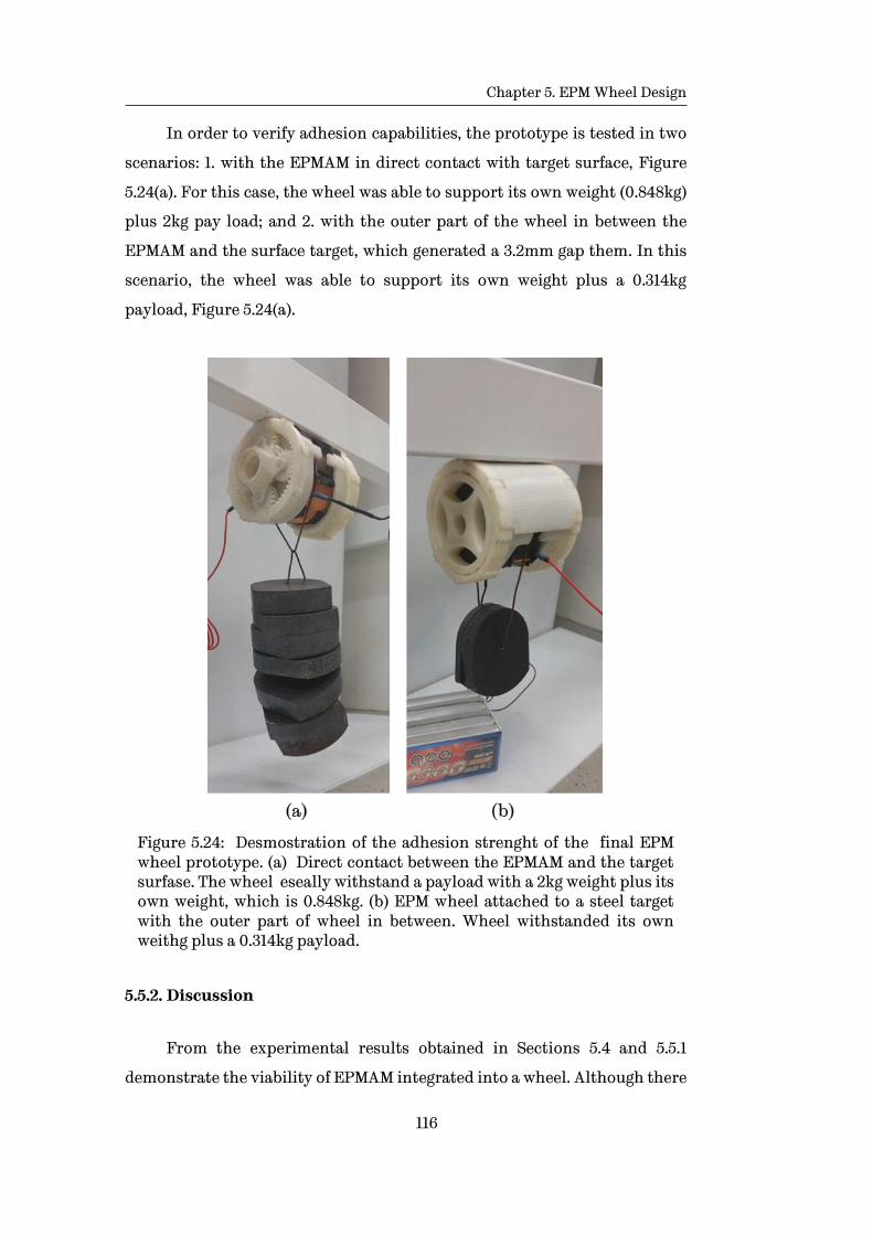
Chapter 5. EPM Wheel Design
116
In order to verify adhesion capabilities, the prototype is tested in two
scenarios: 1. with the EPMAM in direct contact with target surface, Figure
5.24(a). For this case, the wheel was able to support its own weight (0.848kg)
plus 2kg pay load; and 2. with the outer part of the wheel in between the
EPMAM and the surface target, which generated a 3.2mm gap them. In this
scenario, the wheel was able to support its own weight plus a 0.314kg
payload, Figure 5.24(a).
Figure 5.24: Desmostration of the adhesion strenght of the final EPM wheel prototype. (a) Direct contact between the EPMAM and the target surfase. The wheel eseally withstand a payload with a 2kg weight plus its own weight, which is 0.848kg. (b) EPM wheel attached to a steel target with the outer part of wheel in between. Wheel withstanded its own weithg plus a 0.314kg payload.
5.5.2. Discussion
From the experimental results obtained in Sections 5.4 and 5.5.1
demonstrate the viability of EPMAM integrated into a wheel. Although there
Chapter 5. EPM Wheel Design
117
exist differences between the experimental and simulation results, these
differences can be explained by: 1. exist variables that were not included in
the simulations in order to save computational power and time. These
variables (temperature, humidity, external magnetic fields, proximity of
ferric components) by themselves cannot be meaningful in the results, but
all of them combine might be; 2. limitations of the software (ANSYS Maxwell)
used, it was not able to perform the ON-OFF transition.
Results for the magnetic force of the final wheel design, presented in
Section 5.5.1, show that each wheel is able to hold a pay load of 0.314kg. If
implemented in a MR, four wheels will be able hold a 1.2kg MR. Furthermore,
if the thickness of the outer part of the wheel (that separates the EPMAM
from the structure surface) is reduced, the strength of the magnetic force can
be increased. The maximum magnetic force that this specific design can
generate is 2kg, in a direct contact of the EPMAM with the ferric structure.
In terms of energy consumption for performing the switching between
states, each transition pulse consumes 5.27mWh from the battery. This
power is determined using maximum current (≈55A) and pulse length (15ms)
needed for the switching.
𝑃𝑆𝑤𝑖𝑡𝑐ℎ𝑖𝑛𝑔 = 𝑉𝐼𝑡𝑝𝑢𝑙𝑠𝑒 = (23𝑉)(55𝐴)(4.17𝑥10−6ℎ) = 5.27𝑚𝑊ℎ
Considering the battery used for the experiments, which has a
5300mWh capacity, ≈1,000 switching pulses can be delivered by fully charged
battery.
5.6. Concluding remarks
In the present chapter, a detailed analysis an EPMAM wheel design,
using customised components, was performed. The impact of the thickness
of the steel keepers, the gauge of enamelled wire and the presence of an air
gap were examined in order to determine optimum component
configuration. Once the most suitable component’s size was selected the
most feasible configuration, for integrating the EPMAM in a wheel design,

Chapter 5. EPM Wheel Design
118
was explored. The static EPMAM configuration was chosen over the rotating
EPMAM, based on the discussed advantages and disadvantages.
Once the customised components and EPMAM wheel configuration
were established, an EPMAM wheel design was presented based on
manufacturability and fabrication cost considerations. After building the
selected EPMAM design, a set of simulations and experiments were
presented with the aim to verify the performance of the final device. The
outcomes of the simulations and experiments were compared in both,
qualitative and quantitative, ways. In terms of the qualitative results, FEA
simulations and experiments exhibit similar behaviour for the OFF and ON
states, as well as the OFF-ON and ON-OFF switching. However, when
compared a quantitative way, FEA simulations presented a significant
deviation from the experimental outcomes. Some of the main reasons for the
difference was due to the magnetization BH curves, initially used by the FEA
software. For this reason, the magnetization BH curves from the actual PMs
and mild steel materials were requested to the manufacturers. Using the new
magnetisation BH data simulations were repeated, and the results obtained
were more realistic, however, the still were significantly different from the
experimental results. After analysing the possible factors that might have
affected the simulation and based on the experimental results, it was
determined the proposed Novel adhesion mechanism still was feasible and
has potential for being implemented in WCMR.
Finally, an EPM wheel prototype was presented and built using
customised 3D printed plastic components. The final wheel prototype was
tested for to scenarios with a holding payload, which verify that the wheel
remained adhered to the target surface, holding its own weight plus the
added payload.
119
Chapter 6
Conclusions and Future Work
Inspection and maintenance tasks of ferric structures are crucial
preserve the functionality of existing infrastructure. In order to reduce the
risk for humans that have been performing these task, along with the costs
and times for such activities WCMR have been studied in the last decades.
Most of the MR developed for the specific case of ferric structures use
magnetic adhesion mechanism in order to climb vertical structures
performing against gravity. These WCMR use PM magnets as the main source
of magnetic adhesion. However, PMs have a fixed adhesive force, which
means the adhesive force cannot be modified once the MR has been
fabricated. Moreover, if the strength of the adhesion mechanism is not
selected carefully the final adhesive performance could be significantly
affected. A weak adhesive force can result in WCMR not being able to adhere
to the structure. On the other hand, a strong adhesive force reduces
considerably the manoeuvrability of the MR and increases the power
consumption need to move around the structure.
The work presented in this thesis explores a novel magnetic adhesion
mechanism for WCMR used for inspection and/or maintenance tasks in
ferric structures and its implementation in a wheeled locomotion
mechanism.

Chapter 6. Conclusions and Future Work
120
This chapter presents the final conclusions from the work presented
and explores the possible future work for further optimisation of this novel
adhesion mechanism. Throughout the present thesis the following subjects
where covered:
• The current state-of-the-art on MR used for inspection tasks was
presented throughout Chapter 2. Inspection robots were classified
base on their domain and it was established that the most suitable MR
domain for inspection tasks in vertical ferric structures was the
ground domain. Within the ground MR were further examined base on
the type of locomotion and adhesion mechanism. These analysis
showed that the most suitable locomotion mechanism for WCMR used
in ferric structures, due its advantages, was the wheeled mechanism.
In terms of the adhesion mechanism the most feasible mechanism was
determined to be the magnetic adhesion mechanism. Finally, in order
to overcome the limitations of current magnetic adhesion
mechanisms, a novel active magnetic adhesion mechanism using EPMs
was proposed.
• The EPM were explored in more detailed throughout Chapter 3. Their
theory and working principles were presented and their OFF and ON
configurations were examined. Furthermore, the novel characteristic
that allows the EPMs to vary their adhesive force was presented. In
order to validate the feasibility of EPMs as an adhesion mechanism a
preliminary device was constructed using off-the shelf components.
This EPM device was subject of different experiments and
corresponding FEA simulations with the aim to verify its adhesive
capabilities and behaviour for the OFF, ON and variable adhesion
states. Results from both, FEA simulations and experiments validated
the feasibility of the concept and set the basis for more detailed
examination of the concept.
• In Chapter 4, an analysis of the locomotion mechanism for
implementing the EPM as an adhesion mechanism were explored.
After a detailed analysis it was determined that the wheeled
Chapter 6. Conclusions and Future Work
121
locomotion was the most suitable, based in some predefined requisites.
Having selected the locomotion mechanism, different possible
configurations for integrating the EPMAM into a wheeled locomotion
mechanism were explored. After selecting most appropriate
configuration, similarly to Chapter 3, a preliminary device was
constructed using again the same off-the-shelf components. Again a set
of FEA simulations and experiments were performed to the proposed
EPMAM wheel device. Results from both, experiments and simulations
demonstrated the feasibility of a wheel design with an EPMAM as the
main adhesion mechanism.
• In Chapter 5, based on results obtained in Chapter 4, a customised
EPMAM was presented and the influence of each of the individual
components on the performance of the EPMAM was explored. Based on
the results from analysis performed to each of the components a final
EPMAM was built using the customised components. Finally a set of
FEA simulations and experiments were performed and compared in a
quantitative and qualitative way. Qualitative results had similar
outcomes, however quantitative results differed considerably. The
possible causes for the differences were explored and, although
significant difference between experiments and simulations, based on
experimental results the EPMAM was proven to be feasible and with
potential in the WCMR field. Next, a complete wheel prototype was
designed and constructed using 3D printed components. The final
prototype was tested under load scenarios with positive results.
Finally the built prototype was mounted on an off-the-shelf MR.
6.1. Future work
Based on the results obtained through Chapter 5, it was determined
that further work must be performed for selecting which parameters should
be included into the FEA setup for obtaining simulation results close to real
life. The achievements presented in this thesis can be used as base line to

Chapter 6. Conclusions and Future Work
122
extend the research on active magnetic adhesion mechanisms using EPMs
with the following list of possible future work:
• A more detailed examinations of the parameters that have potential
influence on the final performance of the EPMAM, such as temperature
or humidity. Additionally, including effects of motion into the FEA
simulation to explore the impact of the transient oscillations present
in the experiments measurements.
• Design and use of a more robust test bench in order to minimize
external transient effects in the experimental measurements.
• The use of different materials for the keepers. Using materials with
higher magnetic saturations points might enable to increase magnetic
adhesive forces and reducing the total weight of the EPMAM. Some of
the material can be the electrical or silicon steel, permalloy or Mu-
metal.
• Testing the wheel on a MR. As shown in Figure 6.1, building 4 identical
EPM wheels in order to mount them into a MR and testing them in a
real scenario.
Figure 6.1: Final EPM wheel prototype installed ifn a off-the-shelf MR

123
REFERENCES
Agoros, C., 1994. US Navy Unmanned Undersea Vehicle Navigation. In 1994 IEEE Oceans. Brest: IEEE, p. III/372-III/377. Available at: http://ieeexplore.ieee.org/lpdocs/epic03/wrapper.htm?arnumber=364227 [Accessed March 28, 2014].
Asano, K. et al., 1983. Multijoint Inspection Robot. IEEE Transactions on Industrial Electronics, IE-30(3), pp.277–281. Available at: http://ieeexplore.ieee.org/lpdocs/epic03/wrapper.htm?arnumber=4180472.
Autumn, K. et al., 2005. Robotics in Scansorial Environments. In G. R. Gerhart, C. M. Shoemaker, & D. W. Gage, eds. Proceedings of SPIE - Unmanned Ground Vehicle Technology VII. Orlando, pp. 291–302. Available at: http://proceedings.spiedigitallibrary.org/proceeding.aspx?articleid=864272 [Accessed March 21, 2014].
AUVIS, 2013. Unmanned Maritime Vehicles: Core Capabilities and Market Background. The Association for Unmanned Vehicle Systems International, 100, pp.1–16.
Bahr, B., Li, Y. & Najafi, M., 1996. Design and suction cup analysis of a wall climbing robot. Computers and Electrical Engineering, 22(3), pp.193–209.
Balaguer, C., Gimenez, A. & Jordon, A., 2005. Climbing robots’ mobility for inspection and maintenance of 3D complex environments. Autonomous Robots, 18(2), pp.157–169.
Bannon, R.T., 2000. Remotely Operated Vehicles Evolution for Maintenance and Repair of Fiber Optic Systems. In 2000 IEEE Oceans. Providence, RI, RI: IEEE, pp. 489–496. Available at: http://ieeexplore.ieee.org/xpl/articleDetails.jsp?arnumber=881304%5Cnhttp://ieeexplore.ieee.org/lpdocs/epic03/wrapper.htm?arnumber=881304 [Accessed March 28, 2014].
Bovim, K., 2014. Design of a wall-climbing robot system.
Briones, L., Bustamante, P. & Serna, M.A., 1994. Robicen: A wall-climbing pneumatic robot for inspection in nuclear power plants. Robotics and Computer Integrated Manufacturing, 11(4), pp.287–292.
Bruch, M.H. et al., 2005. Advances in Autonomy for Small UGVs. In SPIE Proc. 5804 Unmanned Gr. Veh. Technol. VII.
Bruzzone, L. & Fanghella, P., 2014. Mantis: hybrid leg-wheel ground mobile robot. Industrial Robot: An International Journal, 41(1), pp.26–36.

REFERENCES
124
Bruzzone, L. & Quaglia, G., 2012. Review article: locomotion systems for ground mobile robots in unstructured environments. Mechanical Sciences, 3(2), pp.49–62. Available at: http://www.mech-sci.net/3/49/2012/ [Accessed February 26, 2014].
Burri, M. et al., 2012. Aerial Service Robots for Visual Inspection of Thermal Power Plant Boiler Systems. In 2012 2nd International Conference on Applied Robotics for the Power Industry (CARPI). pp. 70–75.
Byrd, J.S. & DeVries, K.R., 1990. A Six-Legged Telerobot for Nuclear Applications Development. The International Journal of Robotics Research, 9(2), pp.43–52. Available at: http://ijr.sagepub.com/cgi/doi/10.1177/027836499000900204 [Accessed November 22, 2013].
Caprari, G. & Breitenmoser, A., 2012. Highly Compact Robots for Inspection of Power Plants. In 2010 1st International Confconference on Applied Robotics for the Power Industry. Montreal, Canada, pp. 1–6. Available at: http://onlinelibrary.wiley.com/doi/10.1002/rob.21411/full.
Carrara, G., De Paulis, A. & Tantussi, G., 1992. SSR: a mobile robot on ferromagnetic surfaces. Automation in Construction, 1(1), pp.47–53. Available at: http://linkinghub.elsevier.com/retrieve/pii/092658059290036J [Accessed May 22, 2015].
Carroll, D.M., Mikell, K. & Denewiler, T., 2004. Unmanned ground vehicles for integrated force protection, Available at: http://proceedings.spiedigitallibrary.org/proceeding.aspx?articleid=844163.
Cassing, W., Pohl, T. & Steger, F., 2008. Using electro-permanent magnets to lift loads in modern logistics networks. ThyssenKrupp techforum, (1), pp.80–85. Available at: http://cat.inist.fr/?aModele=afficheN&cpsidt=20617234 [Accessed March 7, 2014].
Cho, K.H. et al., 2013. Inspection robot for hanger cable of suspension bridge: Mechanism design and analysis. IEEE/ASME Transactions on Mechatronics, 18(6), pp.1665–1674. Available at: http://ieeexplore.ieee.org/lpdocs/epic03/wrapper.htm?arnumber=6612676 [Accessed March 27, 2014].
Chu, B. et al., 2010. A survey of climbing robots: Locomotion and adhesion. International Journal of Precision Engineering and Manufacturing, 11(4), pp.633–647.
Clapper, J.R. et al., 2009. FY2009-2034 Unmanned Systems Integrated Roadmap, Available at: http://scholar.google.com/scholar?hl=en&btnG=Search&q=intitle:FY2009+?+2034+Unmanned+Systems+Integrated+Roadmap#0 [Accessed February 21, 2014].
Damus, R. et al., 2002. Design of an Inspection Class Autonomous
REFERENCES
125
Underwater Vehicle. In 2002 IEEE Oceans. IEEE, pp. 180–185. Available at: http://ieeexplore.ieee.org/lpdocs/epic03/wrapper.htm?arnumber=1193268.
Debenest, P. et al., 2008. Sensor-arm - Robotic Manipulator for Preventive Maintenance and Inspection of High-voltage Transmission Lines. In 2008 IEEE/RSJ International Conference on Intelligent Robots and Systems, IROS. IEEE, pp. 1737–1744. Available at: http://ieeexplore.ieee.org/lpdocs/epic03/wrapper.htm?arnumber=4650964 [Accessed March 27, 2014].
Defense, U.D. of, 1992. Unmanned Ground Vehicle Master Plan D. O. F. D. W. DC, ed.,
Degani, A. et al., 2007. A dynamic single actuator vertical climbing robot. In 2007 IEEE International Conference on Intelligent Robots and Systems. San Diego, CA, USA: IEEE, pp. 2901–2906. Available at: http://ieeexplore.ieee.org/lpdocs/epic03/wrapper.htm?arnumber=4399200 [Accessed March 27, 2014].
Desbiens, A.L., Asbeck, A. & Cutkosky, M., 2010. Hybrid aerial and scansorial robotics. In 2010 IEEE International Conference on Robotics and Automation. IEEE, pp. 72–77. Available at: http://ieeexplore.ieee.org/lpdocs/epic03/wrapper.htm?arnumber=5509397 [Accessed March 21, 2014].
Elliott, M. et al., 2007. City-Climbers at Work. In Proceedings 2007 IEEE International Conference on Robotics and Automation. IEEE, pp. 2764–2765.
Fernández, R. et al., 2010. A wall climbing robot for tank inspection. An autonomous prototype. In IECON Proceedings (Industrial Electronics Conference). IEEE, pp. 1424–1429. Available at: http://ieeexplore.ieee.org/lpdocs/epic03/wrapper.htm?arnumber=5675473 [Accessed February 22, 2014].
Fischer, W. et al., 2010. Foldable magnetic wheeled climbing robot for the inspection of gas turbines and similar environments with very narrow access holes. Industrial Robot: An International Journal, 37(3), pp.244–249. Available at: http://www.emeraldinsight.com/journals.htm?issn=0143-991X&volume=37&issue=3&articleid=1858511&show=html [Accessed November 22, 2013].
Fischer, W. et al., 2011. Locomotion system for a mobile robot on magnetic wheels with both axial and circumferential mobility and with only an 8-mm height for generator inspection with the rotor still installed. IEEE Transactions on Industrial Electronics, 58(12), pp.5296–5303. Available at: http://ieeexplore.ieee.org/lpdocs/epic03/wrapper.htm?arnumber=5762597 [Accessed February 22, 2014].

REFERENCES
126
Fischer, W., Tache, F. & Siegwart, R., 2007. Inspection system for very thin and fragile surfaces, based on a pair of wall climbing robots with magnetic wheels. In 2007 IEEE International Conference on Intelligent Robots and Systems. San Diego, CA, USA: IEEE, pp. 1216–1221. Available at: http://ieeexplore.ieee.org/lpdocs/epic03/wrapper.htm?arnumber=4399060 [Accessed March 27, 2014].
Fischer, W., Tache, F. & Siegwart, R., 2007. Magnetic Wall Climbing Robot for Thin Surfaces with Specific Obstacles. In 6th International Conference on Field and Service Robotics (FSR). pp. 551–561. Available at: http://hal.inria.fr/inria-00194494 [Accessed March 27, 2014].
Fish, S. & Sitzman, A., 2009. Unmanned vehicles for mobile electromagnetic launch platforms. IEEE Transactions on Magnetics, 45(1), pp.639–640. Available at: http://ieeexplore.ieee.org/lpdocs/epic03/wrapper.htm?arnumber=4773631 [Accessed March 28, 2014].
Fu, G., Menciassi, A. & Dario, P., 2012. Design of a miniature switchable connection system for stochastic modular robots. Sensors and Actuators A: Physical, 173(1), pp.267–276. Available at: http://linkinghub.elsevier.com/retrieve/pii/S0924424711005504 [Accessed March 27, 2014].
Fulbright, R. & Stephens, L.M., 1995. SWAMI: An autonomous mobile robot for inspection of nuclear waste storage facilities. Autonomous Robots, 2(3), pp.225–235. Available at: http://link.springer.com/10.1007/BF00710858 [Accessed March 27, 2014].
Gilbert, P. et al., 2007. Miniature Mobile Robot for Inspection of Ferromagnetic Structures MagBot, Lausanne. Available at: http://citeseerx.ist.psu.edu/viewdoc/download?doi=10.1.1.172.8780&rep=rep1&type=pdf [Accessed February 22, 2014].
Gilpin, K., Knaian, A. & Rus, D., 2010. Robot pebbles: One centimeter modules for programmable matter through self-disassembly. In 2010 IEEE International Conference on Robotics and Automation. IEEE, pp. 2485–2492. Available at: http://ieeexplore.ieee.org/lpdocs/epic03/wrapper.htm?arnumber=5509817 [Accessed March 27, 2014].
Gogarty, B. & Robinson, I., 2011. Unmanned Vehicles: A (Rebooted) History, Background and Current State-Of-the-Art, Available at: http://heinonlinebackup.com/hol-cgi-bin/get_pdf.cgi?handle=hein.journals/jlinfos21§ion=17.
Granosik, G., Hansen, M.G. & Borenstein, J., 2005. The OmniTread serpentine robot for industrial inspection and surveillance. Industrial Robot: An International Journal, 32(2), pp.139–148.
Grieco, J.C. et al., 1998. A six legged climbing robot for high payloads. In

REFERENCES
127
1998 International Conference on Control and Applications. Trieste, Italy: IEEE, pp. 446–450. Available at: http://ieeexplore.ieee.org/xpls/abs_all.jsp?arnumber=728488 [Accessed May 22, 2015].
Gunetti, P., Thompson, H. & Dodd, T., 2011. Autonomous mission management for UAVs using soar intelligent agents. International Journal of Systems Science, 44(5), pp.831–852. Available at: http://www.tandfonline.com/doi/abs/10.1080/00207721.2011.626902 [Accessed February 22, 2014].
Guo, R. et al., 2010. A mobile robot for inspection of substation equipments. In 2010 1st International Conference on Applied Robotics for the Power Industry, CARPI 2010. IEEE, pp. 1–5.
Haas, G.A. et al., 1997. An Unmanned Ground Vehicle for Mine,
Hadfield, D. & Mawson, D.L., 1952. Permanent Magnets for Spectrographs and Nuclear Physical Research. British Journal of Applied Physics, 3(6), pp.199–202.
Haraguchi, R. et al., 2005. The development of the mobile inspection robot for rescue activity, MOIRA2. In 2005 International Conference on Advanced Robotics, ICAR ’05, Proceedings. Seattle, WA, WA, pp. 498–505.
Hirose, S. & Tsutsumitake, H., 1992. Disk Rover: A Wall-climbing Robot Using Permanent. 1992 IEEE/RSJ International Conference on Intelligent Robots and Systems, 3, pp.2074–2079.
Hobson, B. et al., 2001. Development of a Micro Autonomous Underwater Vehicle for Complex 3-D Sensing. In 2001 IEEE Oceans. An Ocean Odyssey. Marine Technol. Soc, pp. 2043–2045. Available at: http://ieeexplore.ieee.org/xpl/articleDetails.jsp?arnumber=968311%5Cnhttp://ieeexplore.ieee.org/lpdocs/epic03/wrapper.htm?arnumber=968311 [Accessed March 28, 2014].
Hrabar, S., Merz, T. & Frousheger, D., 2010. Development of an autonomous helicopter for aerial powerline inspections. In 2010 1st International Conference on Applied Robotics for the Power Industry, CARPI 2010. IEEE, pp. 1–6. Available at: http://ieeexplore.ieee.org/lpdocs/epic03/wrapper.htm?arnumber=5624432 [Accessed March 28, 2014].
Hu, B. et al., 2009. A Miniature Wall Climbing Robot with Biomechanical Suction Cups. Industrial Robot: An International Journal, 36(6), pp.551–561. Available at: http://www.emeraldinsight.com/journals.htm?issn=0143-991X&volume=36&issue=6&articleid=1819209&show=html%5Cnhttp://www.emeraldinsight.com/10.1108/01439910910994623 [Accessed October 31, 2013].
International, S.R.I., 2010. Electroadhesion for Industrial , Biomedical ,

REFERENCES
128
Military , and Consumer Applications. Power. Available at: http://www.sri.com/research-development/robotics [Accessed March 2, 2014].
Jahanian, O. & Karimi, G., 2006. Locomotion Systems in Robotic Application. In 2006 IEEE International Conference on Robotics and Biomimetics, ROBIO 2006. IEEE, pp. 689–696. Available at: http://ieeexplore.ieee.org/lpdocs/epic03/wrapper.htm?arnumber=4141949 [Accessed March 27, 2014].
Ji, C.H. et al., 2004. Electromagnetic 2 ?? 2 MEMS optical switch. IEEE Journal on Selected Topics in Quantum Electronics, 10(3), pp.545–550.
Kalra, L.P. & Gu, J., 2007. An autonomous self contained wall climbing robot for non-destructive inspection of above-ground storage tanks. Industrial Robot: An International Journal, 34(2), pp.122–127. Available at: http://www.emeraldinsight.com/journals.htm?issn=0143-991X&volume=34&issue=2&articleid=1597860&show=html [Accessed March 27, 2014].
Kalra, L.P., Gu, J. & Meng, M., 2006. A Wall Climbing Robot for Oil Tank Inspection. In 2006 IEEE International Conference on Robotics and Biomimetics, ROBIO 2006. IEEE, pp. 1523–1528. Available at: http://ieeexplore.ieee.org/lpdocs/epic03/wrapper.htm?arnumber=4142092 [Accessed March 27, 2014].
Kato, I., 2005. Dynamics of Track - Wheel Systems on High Speed Vehicles. Journal of Meehamcal Science and Technology, 19(1), pp.328–335.
Katrašnik, J., Pernuš, F. & Likar, B., 2010. A survey of mobile robots for distribution power line inspection. IEEE Transactions on Power Delivery, 25(1), pp.485–493. Available at: http://ieeexplore.ieee.org/lpdocs/epic03/wrapper.htm?arnumber=5345712 [Accessed March 27, 2014].
Khirade, N.R., Sanghi, R.K. & Tidke, D.J., 2014. Magnetic Wall Climbing Devices - A Review. , 2014, pp.55–59.
Khurshid, J. & Bing-rong, H., 2004. Military robots-a glimpse from today and tomorrow. In 2004 8th International Conference on Control, Automation, Robotics and Vision. p. 771–777 Vol. 1.
Kim, J.H., Sharma, G. & Iyengar, S.S., 2010. FAMPER: A fully autonomous mobile robot for pipeline exploration. In 2010 IEEE International Conference on Industrial Technology. Ieee, pp. 517–523. Available at: http://ieeexplore.ieee.org/lpdocs/epic03/wrapper.htm?arnumber=5472748.
Kim, S. et al., 2008. Smooth vertical surface climbing with directional adhesion. IEEE Transactions on Robotics, 24(1), pp.65–74.
Knaian, A.N., 2010. Electropermanent Magnetic Connectors and Actuators: Devices and Their Application in Programmable Matter. Massachusetts Institute of Technology. Available at:

REFERENCES
129
http://dspace.mit.edu/handle/1721.1/60151%5Cnhttp://hdl.handle.net/1721.1/60151 [Accessed March 27, 2014].
Knaian, A.N. et al., 2012. The Milli-Motein: A self-folding chain of programmable matter with a one centimeter module pitch. In 2012 IEEE International Conference on Intelligent Robots and Systems. IEEE, pp. 1447–1453. Available at: http://ieeexplore.ieee.org/lpdocs/epic03/wrapper.htm?arnumber=6385904 [Accessed March 27, 2014].
Kolhalkar, N. & Patil, S., 2012. Wall Climbing Robots: A Review. International Journal of Engineering and Innovative Technology, 1(5), pp.227–229. Available at: http://ijeit.com/vol 1/Issue 5/IJEIT1412201205_44.pdf [Accessed February 26, 2014].
Koo, I.M. et al., 2013. Development of wall climbing robot system by using impeller type adhesion mechanism. Journal of Intelligent and Robotic Systems: Theory and Applications, 72(1), pp.57–72. Available at: http://link.springer.com/10.1007/s10846-013-9820-z [Accessed March 27, 2014].
Kwon, Y.-S.K.Y.-S. et al., 2010. A pipeline inspection robot with a linkage type mechanical clutch. In 2010 IEEE International Conference on Intelligent Robots and Systems. IEEE, pp. 2850–2855. Available at: http://ieeexplore.ieee.org/lpdocs/epic03/wrapper.htm?arnumber=5652391 [Accessed March 27, 2014].
Lab, B.M., Biologically Inspired Synthetic Gecko Adhesives. Available at: http://robotics.eecs.berkeley.edu/~ronf/Gecko/.
Lee, B.J. et al., 2008. Optimal design of electro-permanent magnet lifter using improved auto-tuning niching genetic algorithm. In 2007 International Conference on Electrical Machines and Systems. pp. 783–788. Available at: http://ieeexplore.ieee.org/xpls/abs_all.jsp?arnumber=4412219 [Accessed February 22, 2014].
Lee, D. et al., 2012. Novel mechanisms and simple locomotion strategies for an in-pipe robot that can inspect various pipe types. Mechanism and Machine Theory, 56, pp.52–68. Available at: http://www.sciencedirect.com/science/article/pii/S0094114X12001127 [Accessed March 27, 2014].
Liu, D.K. et al., 2008. A Robotic System for Steel Bridge Maintenance: Research Challenges and System Design. 2008 Australasian Conference on Robotics and Automation. Available at: http://www.scopus.com/inward/record.url?eid=2-s2.0-84862909210&partnerID=tZOtx3y1.
Ltd, L.M.P., 2014. Electropermanent Plate Lifting Magnet. , pp.31–33. Available at: http://www.liftonmagnets.com/c-36-lifting-magnets-range.aspx.
M. Lauria; Y. Piguet and R. Siegwart, 2002. Octopus-an Autonomous

REFERENCES
130
Wheeled Climbing Robot. In 5th International Conference onon Climbing and Walking Robots. pp. 1–8. Available at: http://citeseerx.ist.psu.edu/viewdoc/download?doi=10.1.1.149.6526&rep=rep1&type=pdf.
Mae, Y. & Ohara, K., 2009. Wheel Hybrid Loeomotion for Multi Legged Robot. The Japan Society fo Mechanical Engineers.
Manley, J.E., 2008. Unmanned surface vehicles, 15 years of development. Oceans 2008, pp.1–4. Available at: http://ieeexplore.ieee.org/lpdocs/epic03/wrapper.htm?arnumber=5152052.
Marchese, A.D., Asada, H. & Rus, D., 2012. Controlling the locomotion of a separated inner robot from an outer robot using electropermanent magnets. In 2012 IEEE International Conference on Robotics and Automation. IEEE, pp. 3763–3770. Available at: http://ieeexplore.ieee.org/lpdocs/epic03/wrapper.htm?arnumber=6225034 [Accessed March 27, 2014].
Marchese, A.D., Onal, C.D. & Rus, D., 2011. Soft robot actuators using energy-efficient valves controlled by electropermanent magnets. In 2012 IEEE International Conference on Intelligent Robots and Systems. IEEE, pp. 756–761. Available at: http://ieeexplore.ieee.org/lpdocs/epic03/wrapper.htm?arnumber=6095064 [Accessed March 25, 2014].
Menon, C., Murphy, M. & Sitti, M., 2004. Gecko Inspired Surface Climbing Robots. In 2004 IEEE International Conference on Robotics and Biomimetics. Ieee, pp. 431–436. Available at: http://ieeexplore.ieee.org/lpdocs/epic03/wrapper.htm?arnumber=1521817 [Accessed March 27, 2014].
Michaud, F. et al., 2003. AZIMUT, a leg-track-wheel robot. 2003 IEEE/RSJ International Conference on Intelligent Robots and Systems, 3(October), pp.2553–2558. Available at: http://ieeexplore.ieee.org/lpdocs/epic03/wrapper.htm?arnumber=1249254.
Michaud, F. et al., 2005. Multi-modal locomotion robotic platform using leg-track-wheel articulations. Autonomous Robots, 18(2), pp.137–156.
Miyake, T., Ishihara, H. & Yoshimura, M., 2007. Basic studies on wet adhesion system for wall climbing robots. In 2007 IEEE International Conference on Intelligent Robots and Systems. IEEE, pp. 1920–1925. Available at: http://ieeexplore.ieee.org/lpdocs/epic03/wrapper.htm?arnumber=4399417 [Accessed March 27, 2014].
Murphy, M.P. et al., 2011. Waalbot II: Adhesion Recovery and Improved Performance of a Climbing Robot using Fibrillar Adhesives. The International Journal of Robotics Research, 30(1), pp.118–133. Available at: http://ijr.sagepub.com/cgi/doi/10.1177/0278364910382862 [Accessed
REFERENCES
131
October 31, 2013].
Nave, C.R., 2017. HyperPhysics. Available at: http://hyperphysics.phy-astr.gsu.edu/hbase/magnetic/magfie.html [Accessed March 29, 2017].
Nie, C., Pacheco Corcho, X. & Spenko, M., 2013. Robots on the move: Versatility and complexity in mobile robot locomotion. IEEE Robotics and Automation Magazine, 20(4), pp.72–82. Available at: http://www.nature.com/scientificamerican/journal/v295/n6/full/scientificamerican1206-57a.html [Accessed February 22, 2014].
Nishi, A., 1996. Development of wall-climbing robots. Computers and Electrical Engineering, 22(2), pp.123–149. Available at: http://www.sciencedirect.com/science/article/pii/0045790695000348 [Accessed March 27, 2014].
Okamoto, J. et al., 2012. Development of an autonomous robot for gas storage spheres inspection. Journal of Intelligent and Robotic Systems: Theory and Applications, 66(1–2), pp.23–35. Available at: http://link.springer.com/10.1007/s10846-011-9607-z [Accessed February 21, 2014].
Oliveira, A.L.C., Silva, M.F. & Barbosa, R.S., 2010. Architecture of an wheeled climbing robot with dynamic adjustment of the adhesion system. In 2010 8th IEEE International Symposium on Intelligent Systems and Informatics. Ieee, pp. 127–132.
Ondreička, J. & Paľa, J., 2010. Design and Experimental Examination of New Type of Electro-Permanent Magnet Chuck. Journal of Electrical Engineering, 61(7), pp.152–155. Available at: http://iris.elf.stuba.sk/cgi-bin/jeeec?act=abs&no=7s_110&ttl=42 [Accessed March 7, 2014].
Online, K.& L., 2016. Tables of Physical & Chemical Constants. 16th edition 1995. Available at: http://www.kayelaby.npl.co.uk/general_physics/2_6/2_6_6.html.
Palmer, L.R., Diller, E.D. & Quinn, R.D., 2009. Design of a wall-climbing hexapod for advanced maneuvers. In 2009 IEEE/RSJ International Conference on Intelligent Robots and Systems, IROS 2009. IEEE, pp. 625–630. Available at: http://ieeexplore.ieee.org/lpdocs/epic03/wrapper.htm?arnumber=5354753 [Accessed March 27, 2014].
Pascoal, a. et al., 2000. Robotic ocean vehicles for marine science applications: the European ASIMOV project. In 2000 IEEE Oceans. IEEE, pp. 409–415. Available at: http://ieeexplore.ieee.org/Xplore/cookiedetectresponse.jsp?reload=true [Accessed March 28, 2014].
Perhinschi, M.G.G., Napolitano, M.R.R. & Tamayo, S., 2010. Integrated Simulation Environment for Unmanned Autonomous Systems—Towards a Conceptual Framework. Modelling and Simulation in Engineering, 2010, pp.1–12.
REFERENCES
132
Peyvandi, A., Soroushian, P. & Lu, J., 2013. A New Self-Loading Locomotion Mechanism for Wall Climbing Robots Employing Biomimetic Adhesives. Journal of Bionic Engineering, 10(1), pp.12–18. Available at: http://linkinghub.elsevier.com/retrieve/pii/S1672652913601948 [Accessed February 22, 2014].
Piranda, B. et al., 2013. A new concept of planar self-reconfigurable modular robot for conveying microparts. Mechatronics, 23(7), pp.906–915. Available at: http://www.sciencedirect.com/science/article/pii/S0957415813001633 [Accessed February 22, 2014].
Prahlad, H. et al., 2008. Electroadhesive robots - Wall climbing robots enabled by a novel, robust, and electrically controllable adhesion technology. In 2008 IEEE International Conference on Robotics and Automation. IEEE, pp. 3028–3033. Available at: http://ieeexplore.ieee.org/lpdocs/epic03/wrapper.htm?arnumber=4543670 [Accessed December 1, 2013].
Pranoto, T. et al., 2007. Vibration suppression device using permanent-electromagnet and MRF shear damper. Journal of Materials Processing Technology, 181(1–3 SPEC. ISS.), pp.235–240. Available at: http://www.sciencedirect.com/science/article/pii/S0924013606001749 [Accessed March 7, 2014].
ROCHAT, F. et al., 2010. DESIGN OF MAGNETIC SWITCHABLE DEVICE (MSD) AND APPLICATIONS IN CLIMBING ROBOT. In Clawar 2010. World Scientific Publishing Co. Pte. Ltd., pp. 375–382. Available at: http://www.worldscientific.com/doi/10.1142/9789814329927_0047.
Roman, H.T., 1991. Robots Cut Risks and Costs in Nuclear Power Plants. IEEE Computer Applications in Power, 4(3), pp.11–15. Available at: http://ieeexplore.ieee.org/lpdocs/epic03/wrapper.htm?arnumber=85957 [Accessed March 27, 2014].
Sahay, R. et al., 2015. A State-of-the-Art Review and Analysis on the Design of Dry Adhesion Materials for Applications such as Climbing Micro-robots. RSC Advances, 5(1), pp.50821–50832. Available at: http://pubs.rsc.org/en/Content/ArticleLanding/2015/RA/C5RA06770G.
Santos, D. et al., 2008. Gecko-inspired climbing behaviors on vertical and overhanging surfaces. In 2008 IEEE International Conference on Robotics and Automation. IEEE, pp. 1125–1131. Available at: http://ieeexplore.ieee.org/lpdocs/epic03/wrapper.htm?arnumber=4543355 [Accessed March 27, 2014].
Santos, M.F. et al., 2013. Development of an Underwater Riser Inspection Robot. Industrial Robot: An International Journal, 40(4), pp.402–411. Available at: http://www.emeraldinsight.com/10.1108/01439911311320895 [Accessed December 1, 2013].
Schmidt, D. & Berns, K., 2013. Climbing robots for maintenance and
REFERENCES
133
inspections of vertical structures - A survey of design aspects and technologies. Robotics and Autonomous Systems, 61(12), pp.1288–1305.
Schoeneich, P. et al., 2011. TRIPILLAR: a miniature magnetic caterpillar climbing robot with plane transition ability. Robotica, 29(7), pp.1075–1081. Available at: http://www.journals.cambridge.org/abstract_S0263574711000257 [Accessed April 2, 2014].
Shen, Z.H. & Seipel, J.E., 2012. A fundamental mechanism of legged locomotion with hip torque and leg damping. Bioinspiration & Biomimetics, 7(4), p.46010.
Shirazee, N.A. & Basak, A., 1995. Electropermanent suspension system for acquiring large air-gaps to suspend loads. IEEE Transactions on Magnetics, 31(6 pt 2), pp.4193–4195. Available at: http://ieeexplore.ieee.org/lpdocs/epic03/wrapper.htm?arnumber=489923 [Accessed March 27, 2014].
Shiroma, N. et al., 2006. Development and control of a high maneuverability wheeled robot with variable-structure functionality. In 2006 IEEE International Conference on Intelligent Robots and Systems. pp. 4000–4005.
Smith, H., 2001. U-99 Uninhabited Tactical Aircraft Preliminary Systems Design. Aircraff Engineering and Aerospace Tecnology, 73(3), pp.244–267. Available at: http://www.emeraldinsight.com/journals.htm?issn=0002-2667&volume=73&issue=3&articleid=876537&show=html.
Smith, J.A., Sharf, I. & Trentini, M., 2006. Bounding gait in a hybrid wheeled-leg robot. In 2006 IEEE International Conference on Intelligent Robots and Systems. pp. 5750–5755.
De Sousa, J.B. & Andrade Gonçalves, G., 2011. Unmanned vehicles for environmental data collection. Clean Technologies and Environmental Policy, 13(2), pp.369–380. Available at: http://link.springer.com/10.1007/s10098-010-0313-5 [Accessed February 15, 2014].
Tache, F. et al., 2007. Adapted magnetic wheel unit for compact robots inspecting complex shaped pipe structures. IEEE/ASME International Conference on Advanced Intelligent Mechatronics, AIM, pp.1–6.
Tavakoli, M. et al., 2013. OmniClimbers: Omni-directional magnetic wheeled climbing robots for inspection of ferromagnetic structures. Robotics and Autonomous Systems, 61(9), pp.997–1007. Available at: http://linkinghub.elsevier.com/retrieve/pii/S0921889013001024 [Accessed November 22, 2013].
Tavakoli, M. et al., 2015. The hybrid OmniClimber robot: Wheel based climbing, arm based plane transition, and switchable magnet adhesion. Mechatronics, 36, pp.136–146.

REFERENCES
134
Tavakoli, M., Marques, L. & Almeida, A.T. De, 2010. Development of an industrial pipeline inspection robot. Industrial Robot: An International Journal, 37(3), pp.309–322. Available at: http://www.emeraldinsight.com/journals.htm?issn=0143-991X&volume=37&issue=3&articleid=1858520&show=html [Accessed March 27, 2014].
Ting Wang, Yuechao Wang & Chen Yao, 2005. Study on Mechanism of a Mobile Robot Used Unstructured Environment. In 2005 IEEE International Conference on Robotics and Biomimetics - ROBIO. IEEE, pp. 201–205. Available at: http://ieeexplore.ieee.org/lpdocs/epic03/wrapper.htm?arnumber=1708622 [Accessed March 27, 2014].
US DoD, 2013. Unmanned Systems Integrated roadmap 2013-2038 O. O. F. T. H. E. U. S. O. F. D. (ACQUISITION T. A. N. D. L. W. DC, ed. FY, p.168.
Wang, H. et al., 2010. Development of an inspection robot for 500 kV EHV power transmission lines. In 2010 IEEE International Conference on Intelligent Robots and Systems. pp. 5107–5112.
Wang, H., Yamamoto, A. & Higuchi, T., 2012. Electrostatic-motor-driven electroadhesive robot. In 2012 IEEE International Conference on Intelligent Robots and Systems. Ieee, pp. 914–919. Available at: http://ieeexplore.ieee.org/lpdocs/epic03/wrapper.htm?arnumber=6385758 [Accessed March 27, 2014].
Wang, Z. & Gu, H., 2007. A review of locomotion mechanisms of urban search and rescue robot. Industrial Robot: An International Journal, 34(5), pp.400–411. Available at: http://www.emeraldinsight.com/10.1108/01439910710774403 [Accessed February 22, 2014].
Ward, P. & Liu, D., 2012. Design of a high capacity Electro Permanent Magnetic adhesion for climbing robots. In 2012 IEEE International Conference on Robotics and Biomimetics, ROBIO 2012 - Conference Digest. Ieee, pp. 217–222. Available at: http://ieeexplore.ieee.org/lpdocs/epic03/wrapper.htm?arnumber=6490969 [Accessed March 27, 2014].
Winkvist, S., Rushforth, E. & Young, K., 2013. Towards an Autonomous Indoor Aerial Inspection Vehicle. Industrial Robot: An International Journal, 40(3), pp.196–207. Available at: http://www.emeraldinsight.com/journals.htm?issn=0143-991X&volume=40&issue=3&articleid=17086376&show=html%5Cnhttp://www.emeraldinsight.com/10.1108/01439911311309870 [Accessed November 14, 2013].
Xiao, J. et al., 2006. Climber: A New Generation of Mobile Robot with Wall-climbing Capability G. R. Gerhart, C. M. Shoemaker, & D. W. Gage, eds. Proceedings of SPIE - The International Society for Optical Engineering, 6230 II(October), p.62301D–62301D–10. Available at: http://www.scopus.com/inward/record.url?eid=2-s2.0-

REFERENCES
135
33748552307&partnerID=tZOtx3y1 [Accessed December 1, 2013].
Xiao, J. & Zhu, Z., 2009. Cooperative Wall-climbing Robots in 3D Environments for Surveillance and Target Tracking, New York. Available at: http://find.shef.ac.uk/primo_library/libweb/action/search.do?dscnt=0&vl(38298075UI4)=00&scp.scps=primo_central_multiple_fe&tab=remote&dstmp=1395933932126&vl(38298080UI0)=title&srt=date&mode=Advanced&vl(38298077UI4)=Year&vl(1UIStartWith1)=contains&tb=t&ind [Accessed March 27, 2014].
Xingguang, D. et al., 2006. MOBIT, A small wheel -track- leg mobile robot. In 6th World Congress on Intelligent Control and Automation. pp. 9159–9163.
Xu, Z.Y. et al., 2015. Design and optimization of magnetic wheel for wall climbing robot. In 2010 EEE International Conferenece on Mechatronics and Automation. Ieee, pp. 619–629. Available at: http://ieeexplore.ieee.org/lpdocs/epic03/wrapper.htm?arnumber=5589061.
Yoon, K.H. & Park, Y.W., 2012. Design, fabrication, and characterization of in-pipe robot with controllable magnetic force. In 8th IEEE International Conference on Automation Science and Engineering. Seoul, Korea: Ieee, pp. 786–789. Available at: http://ieeexplore.ieee.org/lpdocs/epic03/wrapper.htm?arnumber=6386443 [Accessed March 27, 2014].
Yoshida, Y. & Ma, S., 2010. Design of a wall-climbing robot with passive suction cups. In 2010 IEEE International Conference on Robotics and Biomimetics, ROBIO 2010. IEEE, pp. 1513–1518. Available at: http://ieeexplore.ieee.org/lpdocs/epic03/wrapper.htm?arnumber=5723554 [Accessed April 2, 2014].
Yun, H.B. et al., 2013. Development of inspection robots for bridge cables. The Scientific World Journal, 2013(ii), p.967508. Available at: http://www.pubmedcentral.nih.gov/articlerender.fcgi?artid=3888749&tool=pmcentrez&rendertype=abstract [Accessed March 27, 2014].
Zhang, Y. & Dodd, T., 2011. Systematic design of flexible magnetic wall and ceiling climbing robot for cargo screening. In R. Groß et al., eds. Lecture Notes in Computer Science (including subseries Lecture Notes in Artificial Intelligence and Lecture Notes in Bioinformatics). Lecture Notes in Computer Science. Springer Berlin Heidelberg, pp. 414–415.
Zwicker, E., Zesch, W. & Moser, R., 2010. A modular inspection robot platform for power plant applications. In 2010 1st International Conference on Applied Robotics for the Power Industry, CARPI 2010. IEEE, pp. 1–6. Available at: http://ieeexplore.ieee.org/lpdocs/epic03/wrapper.htm?arnumber=5624429 [Accessed February 22, 2014].