Design of Inhomogeneous All-Dielectric Electromagnetic ...
5
732 IEEE ANTENNAS AND WIRELESS PROPAGATION LETTERS, VOL. 18, NO. 4, APRIL2019 Design of Inhomogeneous All-Dielectric Electromagnetic-Wave Diffusive Reflectarray Metasurface Mustafa K. Taher Al-Nuaimi , Yejun He , Senior Member, IEEE, and Wei Hong , Fellow, IEEE Abstract—In this letter, inhomogeneous, single-layer, all- dielectric, nonabsorptive 1-bit and 2-bit coding diffusive reflec- tarray metasurfaces for nearly uniform low-level electromagnetic wave diffusion under a wide range of incident angles (up to 60°) around 12 GHz are proposed. The proposed metasurface consists of a number of small-sized dielectric reflectarrays of unit cells ex- hibiting a parabolic reflection phase profile, i.e., focusing reflection phase, and these reflectarrays are distributed across the metasur- face aperture according to optimized 1-bit and 2-bit coding se- quences to ensure a low level of diffusive scattering in all directions in the half-space in front of the surface. The proposed metasur- faces are realized using all-dielectric unit cells of subwavelength periodicity to achieve the required reflection phase correction (and effective permittivity) at each unit cell inside the small-sized di- electric reflectarrays and to realize the coding particles of the 1-bit and 2-bit coding sequences. The final design metasurface is con- stituted by 4 × 4 small-sized dielectric reflectarrays, and there are 25 (5 × 5) dielectric unit cells in each reflectarray. The pow- erfulness of the presented diffusive reflectarray metasurface and its ability to achieve low-scattering field patterns under both nor- mal and oblique incidence are demonstrated by means of full-wave simulations and experiments. Index Terms—Metasurface, radar cross section, reflectarray. I. INTRODUCTION M ETASURFACE is a kind of artificial material, which is considered as the 2-D planar version of metamaterial, composed of a periodic (or nonperiodic) metallic (or dielectric) array of inclusions (unit cells) of subwavelength size. Metasur- face allows one to fully control the direction of propagation, phase front, amplitude, pattern shape, polarization state, and even the propagation modes of refracted/reflected electromag- netic (EM) wave [1]–[4]. Manuscript received January 21, 2019; revised February 12, 2019; ac- cepted February 21, 2019. Date of publication February 26, 2019; date of current version April 5, 2019. This work was supported in part by the Na- tional Natural Science Foundation of China under Grants 61871433 and 61828103; in part by the Shenzhen Science and Technology Programs un- der Grants GJHZ20180418190529516, JCYJ20170302150411789, JCYJ2017 0302142515949, and GCZX2017040715180580; and in part by the Guangzhou Science and Technology Program under Grant 201707010490. (Corresponding author: Yejun He.) M. K. T. Al-Nuaimi and Y. He are with the Shenzhen Key Laboratory of Antennas and Propagation, College of Information Engineering, Shenzhen University, Shenzhen 518060, China (e-mail:, [email protected]; [email protected]). W. Hong is with the State Key Laboratory of Millimeter Waves, School of Information Science and Engineering, Southeast University, Nanjing 210096, China (e-mail:, [email protected]). Digital Object Identifier 10.1109/LAWP.2019.2901843 Backscattering manipulation and radar cross section (RCS) reduction based on metasurface have been a hot topic recently [5]–[8]. For example, in checkerboard [7] and chessboard [8] surfaces, the monostatic RCS reduction would occur in the bore- sight direction, and the backscattered main lobes will be directed away from the source along the diagonal directions (ϕ = 45°, 135°, 225°, and 315°). To achieve nearly uniform diffused backscattered patterns of low level in more directions other than diagonals in the space in front of the metasurface with good scattering performances at off-normal incidences, unit cells can be distributed across the metasurface aperture according to a certain coding sequence or distribution map, and it is called coding metasurface nowadays [5], [6]. The concept of coding metasurface was proposed in [5] by designing two distinct coding unit cells with opposite reflection phases 0° and 180° to represent the digital states “0” and “1,” respectively, of the (for example) 1-bit coding sequence [9]. Based on coding metasurface concept, several designs have been introduced recently for RCS reduction and EM wave diffu- sion, for instance, combining the cross-polarization conversion with coding metasurface concept [10], diffusive metasurface based on Pancharatnam–Berry unit cell to form small subar- rays exhibiting a focusing reflection phase profile [1], [2], spiral coded metasurface [11], and geometric-phase coded metasur- faces [12]. In this letter, the design of inhomogeneous, single-layer, all- dielectric, nonabsorptive 1-bit and 2-bit coding diffusive reflec- tarray metasurfaces for nearly uniform low-level EM wave dif- fusion under a wide range of incident angles (up to 60°) around 12 GHz is proposed. The proposed metasurface consists of a number of small-sized dielectric reflectarrays of unit cells ex- hibiting a parabolic reflection phase profile. These small-sized reflectarrays are distributed across the metasurface aperture ac- cording to optimized 1-bit and 2-bit coding sequences to ensure a low-level diffusive scattering in all directions. II. THEORY OF THE PROPOSED SURFACES In conventional reflectarray, which imitates conventional parabolic reflector [13], [14], the feeding antenna (horn or patch antenna) illuminates the phasing elements (also called unit cells or scatterers) of individually predesigned phases to generate a collimated beam in a desired direction and convert the incident EM wave of spherical phase front to planar phase front in a con- cept similar to that of a classical parabolic reflector. The desired phase shift φ(x ij, y ij ) at each unit cell across the reflectarray aperture to realize phase front transformation can be achieved 1536-1225 © 2019 IEEE. Personal use is permitted, but republication/redistribution requires IEEE permission. See http://www.ieee.org/publications standards/publications/rights/index.html for more information.
Transcript of Design of Inhomogeneous All-Dielectric Electromagnetic ...

732 IEEE ANTENNAS AND WIRELESS PROPAGATION LETTERS, VOL. 18, NO. 4, APRIL 2019
Design of Inhomogeneous All-DielectricElectromagnetic-Wave Diffusive
Reflectarray MetasurfaceMustafa K. Taher Al-Nuaimi , Yejun He , Senior Member, IEEE, and Wei Hong , Fellow, IEEE
Abstract—In this letter, inhomogeneous, single-layer, all-dielectric, nonabsorptive 1-bit and 2-bit coding diffusive reflec-tarray metasurfaces for nearly uniform low-level electromagneticwave diffusion under a wide range of incident angles (up to 60°)around 12 GHz are proposed. The proposed metasurface consistsof a number of small-sized dielectric reflectarrays of unit cells ex-hibiting a parabolic reflection phase profile, i.e., focusing reflectionphase, and these reflectarrays are distributed across the metasur-face aperture according to optimized 1-bit and 2-bit coding se-quences to ensure a low level of diffusive scattering in all directionsin the half-space in front of the surface. The proposed metasur-faces are realized using all-dielectric unit cells of subwavelengthperiodicity to achieve the required reflection phase correction (andeffective permittivity) at each unit cell inside the small-sized di-electric reflectarrays and to realize the coding particles of the 1-bitand 2-bit coding sequences. The final design metasurface is con-stituted by 4 × 4 small-sized dielectric reflectarrays, and thereare 25 (5 × 5) dielectric unit cells in each reflectarray. The pow-erfulness of the presented diffusive reflectarray metasurface andits ability to achieve low-scattering field patterns under both nor-mal and oblique incidence are demonstrated by means of full-wavesimulations and experiments.
Index Terms—Metasurface, radar cross section, reflectarray.
I. INTRODUCTION
M ETASURFACE is a kind of artificial material, which isconsidered as the 2-D planar version of metamaterial,
composed of a periodic (or nonperiodic) metallic (or dielectric)array of inclusions (unit cells) of subwavelength size. Metasur-face allows one to fully control the direction of propagation,phase front, amplitude, pattern shape, polarization state, andeven the propagation modes of refracted/reflected electromag-netic (EM) wave [1]–[4].
Manuscript received January 21, 2019; revised February 12, 2019; ac-cepted February 21, 2019. Date of publication February 26, 2019; date ofcurrent version April 5, 2019. This work was supported in part by the Na-tional Natural Science Foundation of China under Grants 61871433 and61828103; in part by the Shenzhen Science and Technology Programs un-der Grants GJHZ20180418190529516, JCYJ20170302150411789, JCYJ20170302142515949, and GCZX2017040715180580; and in part by the GuangzhouScience and Technology Program under Grant 201707010490. (Correspondingauthor: Yejun He.)
M. K. T. Al-Nuaimi and Y. He are with the Shenzhen Key Laboratory ofAntennas and Propagation, College of Information Engineering, ShenzhenUniversity, Shenzhen 518060, China (e-mail:, [email protected];[email protected]).
W. Hong is with the State Key Laboratory of Millimeter Waves, School ofInformation Science and Engineering, Southeast University, Nanjing 210096,China (e-mail:,[email protected]).
Digital Object Identifier 10.1109/LAWP.2019.2901843
Backscattering manipulation and radar cross section (RCS)reduction based on metasurface have been a hot topic recently[5]–[8]. For example, in checkerboard [7] and chessboard [8]surfaces, the monostatic RCS reduction would occur in the bore-sight direction, and the backscattered main lobes will be directedaway from the source along the diagonal directions (ϕ = 45°,135°, 225°, and 315°).
To achieve nearly uniform diffused backscattered patterns oflow level in more directions other than diagonals in the spacein front of the metasurface with good scattering performancesat off-normal incidences, unit cells can be distributed across themetasurface aperture according to a certain coding sequence ordistribution map, and it is called coding metasurface nowadays[5], [6]. The concept of coding metasurface was proposed in[5] by designing two distinct coding unit cells with oppositereflection phases 0° and 180° to represent the digital states “0”and “1,” respectively, of the (for example) 1-bit coding sequence[9]. Based on coding metasurface concept, several designs havebeen introduced recently for RCS reduction and EM wave diffu-sion, for instance, combining the cross-polarization conversionwith coding metasurface concept [10], diffusive metasurfacebased on Pancharatnam–Berry unit cell to form small subar-rays exhibiting a focusing reflection phase profile [1], [2], spiralcoded metasurface [11], and geometric-phase coded metasur-faces [12].
In this letter, the design of inhomogeneous, single-layer, all-dielectric, nonabsorptive 1-bit and 2-bit coding diffusive reflec-tarray metasurfaces for nearly uniform low-level EM wave dif-fusion under a wide range of incident angles (up to 60°) around12 GHz is proposed. The proposed metasurface consists of anumber of small-sized dielectric reflectarrays of unit cells ex-hibiting a parabolic reflection phase profile. These small-sizedreflectarrays are distributed across the metasurface aperture ac-cording to optimized 1-bit and 2-bit coding sequences to ensurea low-level diffusive scattering in all directions.
II. THEORY OF THE PROPOSED SURFACES
In conventional reflectarray, which imitates conventionalparabolic reflector [13], [14], the feeding antenna (horn or patchantenna) illuminates the phasing elements (also called unit cellsor scatterers) of individually predesigned phases to generate acollimated beam in a desired direction and convert the incidentEM wave of spherical phase front to planar phase front in a con-cept similar to that of a classical parabolic reflector. The desiredphase shift φ(xij, yij ) at each unit cell across the reflectarrayaperture to realize phase front transformation can be achieved
1536-1225 © 2019 IEEE. Personal use is permitted, but republication/redistribution requires IEEE permission.See http://www.ieee.org/publications standards/publications/rights/index.html for more information.
AL-NUAIMI et al.: DESIGN OF INHOMOGENEOUS ALL-DIELECTRIC ELECTROMAGNETIC-WAVE DIFFUSIVE REFLECTARRAY METASURFACE 733
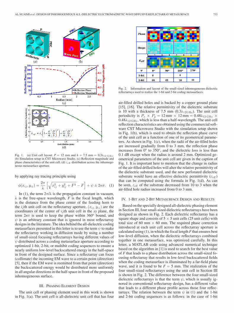
Fig. 1. (a) Unit cell layout: P = 12 mm and h = 7.5 mm = 0.3λ12 GHz .(b) Simulation setup in CST Microwave Studio. (c) Reflection magnitude andphase characteristics of the unit cell. (d) εeff distribution across the inhomoge-neous metasurface aperture.
by applying ray tracing principle using
φ(xij , yij ) =2πλ
[√x2ij + y2
ij + F 2 − F]
+ ψ ± 2nπ. (1)
In (1), the term 2π/λ is the propagation constant in vacuum,λ is the free-space wavelength, F is the focal length, whichis the distance from the phase center of the feeding horn tothe ijth unit cell on the reflectarray aperture, (xij, yij ) are thecoordinates of the center of ijth unit cell in the xy plane, theterm 2nπ is used to keep the phase within 360° bound, andψ is an arbitrary constant that is ignored in most reflectarraydesigns in the literature. The idea behind the all-dielectric codingmetasurfaces presented in this letter is to use the term ψ to makethe reflectarray working in diffusion mode by using a numberof small-sized focusing reflectarrays having different values ofψ distributed across a coding metasurface aperture according tooptimized 1-bit, 2-bit, or multibit coding sequences to ensure anearly uniform low-level backscattered energy in the half-spacein front of the designed surface. Since a reflectarray can focus(collimate) the incoming EM wave to a certain point (direction)[5], then if the EM wave is reemitted from that point (direction)the backscattered energy would be distributed more uniformlyin all angular directions in the half-space in front of the proposedinhomogeneous surface.
III. PHASING ELEMENT DESIGN
The unit cell or phasing element used in this work is shownin Fig. 1(a). The unit cell is all-dielectric unit cell that has four
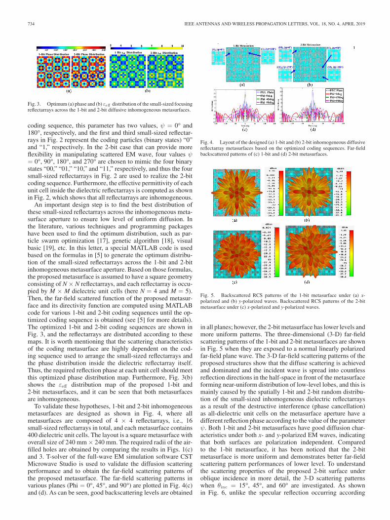
Fig. 2. Information and layout of the small-sized inhomogeneous dielectricreflectarrays used to realize the 1-bit and 2-bit coding metasurfaces.
air-filled drilled holes and is backed by a copper ground plane[15], [16]. The relative permittivity of the dielectric substrateis 10 with a thickness of 7.5 mm (0.3λ12GHz). The unit cellperiodicity is Px × Py = 12 mm × 12 mm = 0.48λ12 GHz ×0.48λ12 GHz , which is less than a half-wavelength. The unit cellreflection characteristics are obtained using the commercial soft-ware CST Microwave Studio with the simulation setup shownin Fig. 1(b), which is used to obtain the reflection phase curveof the unit cell as a function of one of its geometrical parame-ters. As shown in Fig. 1(c), when the radii of the air-filled holesare increased gradually from 0 to 3 mm, the reflection phaseincreases from 0° to 350°, and the dielectric loss is less than0.1 dB except when the radius is around 2 mm. Optimized ge-ometrical parameters of the unit cell are given in the caption ofFig. 1. It is important here to mention that the change in radiusof the air-filled drilled holes will alter the relative permittivity ofthe dielectric substrate used, and the new perforated dielectricsubstrate would have an effective dielectric permittivity (εeff )that can be computed using the formula in Fig. 1(d). As canbe seen, εeff of the substrate decreased from 10 to 3 when theair-filled hole radius increased from 0 to 3 mm.
IV. 1-BIT AND 2-BIT METASURFACE DESIGN AND RESULTS
Based on the specially designed all-dielectric phasing elementin Section III, four small-sized dielectric reflectarrays have beendesigned as shown in Fig. 2. Each dielectric reflectarray has asquare shape and consists of 5 × 5 unit cells (25 unit cells) withtotal size of 60 mm × 60 mm. The required phase correctionintroduced at each unit cell across the reflectarray aperture iscalculated using (1), in which the focal length F that ensures bestlow-level diffusion, when the dielectric reflectarrays combinedtogether in one metasurface, was optimized carefully. In thisletter, a MATLAB code using advanced numerical techniquebased on the algorithm in [1] is used to search for the best valueof F that leads to a phase distribution across the small-sized fo-cusing reflectarray that results in low-level backscattered fieldswhen the coding metasurface is illuminated by a far-field planewave, and it is found to be F = 5 mm. The realization of thefour small-sized reflectarrays using the unit cell in Section IIIis shown in Fig. 2. The difference between the four small-sizeddielectric reflectarrays is that the term ψ, which is usually ig-nored in conventional reflectarray design, has a different valuethat leads to a different phase profile across those four reflec-tarrays. The relation between the term ψ in (1) and the 1-bitand 2-bit coding sequences is as follows: in the case of 1-bit
734 IEEE ANTENNAS AND WIRELESS PROPAGATION LETTERS, VOL. 18, NO. 4, APRIL 2019
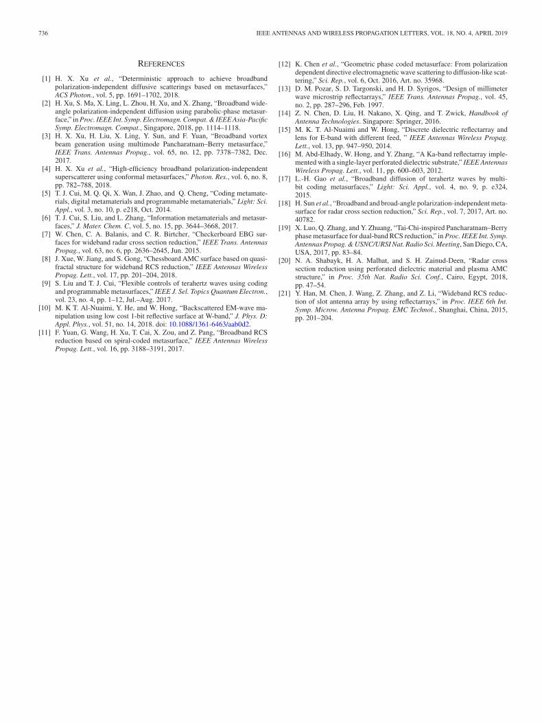
Fig. 3. Optimum (a) phase and (b) εeff distribution of the small-sized focusingreflectarrays across the 1-bit and 2-bit diffusive inhomogeneous metasurfaces.
coding sequence, this parameter has two values, ψ = 0° and180°, respectively, and the first and third small-sized reflectar-rays in Fig. 2 represent the coding particles (binary states) “0”and “1,” respectively. In the 2-bit case that can provide moreflexibility in manipulating scattered EM wave, four values ψ= 0°, 90°, 180°, and 270° are chosen to mimic the four binarystates “00,” “01,” “10,” and “11,” respectively, and thus the foursmall-sized reflectarrays in Fig. 2 are used to realize the 2-bitcoding sequence. Furthermore, the effective permittivity of eachunit cell inside the dielectric reflectarrays is computed as shownin Fig. 2, which shows that all reflectarrays are inhomogeneous.
An important design step is to find the best distribution ofthese small-sized reflectarrays across the inhomogeneous meta-surface aperture to ensure low level of uniform diffusion. Inthe literature, various techniques and programming packageshave been used to find the optimum distribution, such as par-ticle swarm optimization [17], genetic algorithm [18], visualbasic [19], etc. In this letter, a special MATLAB code is usedbased on the formulas in [5] to generate the optimum distribu-tion of the small-sized reflectarrays across the 1-bit and 2-bitinhomogeneous metasurface aperture. Based on those formulas,the proposed metasurface is assumed to have a square geometryconsisting of N × N reflectarrays, and each reflectarray is occu-pied by M × M dielectric unit cells (here N = 4 and M = 5).Then, the far-field scattered function of the proposed metasur-face and its directivity function are computed using MATLABcode for various 1-bit and 2-bit coding sequences until the op-timized coding sequence is obtained (see [5] for more details).The optimized 1-bit and 2-bit coding sequences are shown inFig. 3, and the reflectarrays are distributed according to thesemaps. It is worth mentioning that the scattering characteristicsof the coding metasurface are highly dependent on the cod-ing sequence used to arrange the small-sized reflectarrays andthe phase distribution inside the dielectric reflectarray itself.Thus, the required reflection phase at each unit cell should meetthis optimized phase distribution map. Furthermore, Fig. 3(b)shows the εeff distribution map of the proposed 1-bit and2-bit metasurfaces, and it can be seen that both metasurfacesare inhomogeneous.
To validate these hypotheses, 1-bit and 2-bit inhomogeneousmetasurfaces are designed as shown in Fig. 4, where allmetasurfaces are composed of 4 × 4 reflectarrays, i.e., 16small-sized reflectarrays in total, and each metasurface contains400 dielectric unit cells. The layout is a square metasurface withoverall size of 240 mm × 240 mm. The required radii of the air-filled holes are obtained by comparing the results in Figs. 1(c)and 3. T-solver of the full-wave EM simulation software CSTMicrowave Studio is used to validate the diffusion scatteringperformance and to obtain the far-field scattering patterns ofthe proposed metasurface. The far-field scattering patterns invarious planes (Phi = 0°, 45°, and 90°) are plotted in Fig. 4(c)and (d). As can be seen, good backscattering levels are obtained
Fig. 4. Layout of the designed (a) 1-bit and (b) 2-bit inhomogeneous diffusivereflectarray metasurfaces based on the optimized coding sequences. Far-fieldbackscattered patterns of (c) 1-bit and (d) 2-bit metasurfaces.
Fig. 5. Backscattered RCS patterns of the 1-bit metasurface under (a) x-polarized and (b) y-polarized waves. Backscattered RCS patterns of the 2-bitmetasurface under (c) x-polarized and y-polarized waves.
in all planes; however, the 2-bit metasurface has lower levels andmore uniform patterns. The three-dimensional (3-D) far-fieldscattering patterns of the 1-bit and 2-bit metasurfaces are shownin Fig. 5 when they are exposed to a normal linearly polarizedfar-field plane wave. The 3-D far-field scattering patterns of theproposed structures show that the diffuse scattering is achievedand dominated and the incident wave is spread into countlessreflection directions in the half-space in front of the metasurfaceforming near-uniform distribution of low-level lobes, and this ismainly caused by the spatially 1-bit and 2-bit random distribu-tion of the small-sized inhomogeneous dielectric reflectarraysas a result of the destructive interference (phase cancellation)as all-dielectric unit cells on the metasurface aperture have adifferent reflection phase according to the value of the parameterψ. Both 1-bit and 2-bit metasurfaces have good diffusion char-acteristics under both x- and y-polarized EM waves, indicatingthat both surfaces are polarization independent. Comparedto the 1-bit metasurface, it has been noticed that the 2-bitmetasurface is more uniform and demonstrates better far-fieldscattering pattern performances of lower level. To understandthe scattering properties of the proposed 2-bit surface underoblique incidence in more detail, the 3-D scattering patternswhen θinc = 15°, 45°, and 60° are investigated. As shownin Fig. 6, unlike the specular reflection occurring according

AL-NUAIMI et al.: DESIGN OF INHOMOGENEOUS ALL-DIELECTRIC ELECTROMAGNETIC-WAVE DIFFUSIVE REFLECTARRAY METASURFACE 735
Fig. 6. Far-field 3-D scattering patterns under oblique incidence: PEC platewhen θinc = (a) 15°, (b) 45°, and (c) 60°; 1-bit metasurface when θinc = (d)15°, (e) 45°, and (f) 60°; and 2-bit metasurface when θinc = (g) 15°, (h) 45°,and (i) 60°.
to the classical Snell’s law of reflection with angle of inci-dence equal to the angle of reflection (θinc = θref ) and directivepencil-like beam, the proposed 1-bit and 2-bit metasurfacesredirect the incident energy under oblique incidence intoinnumerable directions (angles), and the 2-bit metasurface hasbetter scattering characteristics compared to the 1-bit surface.Compared to other designs in the literature for RCS reductionbased on focusing phase technique and multibeam reflectarraytechnique, for instance, [20], [21], the proposed codingreflectarray metasurface has better diffusion characteristicsin terms of RCS reduction bandwidth, shape of the scatteredpatterns, and diffuse scattering under oblique incidence.
V. FABRICATION AND MEASUREMENT RESULTS
To experimentally verify the proposed design, a 2-bit meta-surface sample was fabricated through a standard printed cir-cuit board technology as shown in Fig. 7(a). The fabricated2-bit metasurface sample is composed of 20 × 20 unit cellsand has an overall size of 240 × 240 mm2. The measure-ment setup is composed of a Keysight E5071C vector networkanalyzer and a pair of broadband horn antennas (marked asHorn#1 and Horn#2) is utilized with Horn#1 as a transmit-ter and Horn#2 serving as receiver to collect the reflected en-ergy, and the horn antennas are connected to the two ports ofthe network analyzer. The sample under test was positionedin front of the horn antennas, and the centers of Horn#1,Horn#2, and the sample were placed at the same height toensure normal incidence. The distance between the sampleand the horn antennas is chosen carefully to satisfy the well-known far-field formula (R > 2D2/λ). Furthermore, a smallultrathin piece of absorbing material was inserted between thehorn antennas to reduce the undesired coupling and interfer-ence between the transmitted and reflected waves. First and forsake of normalization (calibration), a bare copper plate with thesame size as the 2-bit sample under test was measured. Fig. 8shows the measured RCS of the 2-bit metasurface under both x-and y-polarized waves; in both cases, a clear reduction of morethan 6 dB in the backscattered wave is achieved over the de-
Fig. 7. (a) Photograph of the fabricated sample. (b) Measurement setup insidean anechoic chamber.
Fig. 8. Measured monostatic RCS under (a) x-polarized and (b) y-polarizedEM waves.
sired frequency band. This reduction in the backward reflectionenergy (RCS) is a result of the redistribution of the scatteredenergy as shown in Section IV, and the 2-bit surface mimicsa diffuse reflection surface. The simulation and measurementresults are in a reasonable agreement with a little discrepancycaused by the misalignment of the horn antennas and the sam-ple under test, fabrication error, and uncertainty of the dielectricconstant of the material used at this frequency band.
VI. CONCLUSION
The design of all-dielectric 1-bit and 2-bit diffusive reflectar-ray metasurfaces was presented and investigated. The proposedmetasurfaces used 16 small-sized focusing reflectarrays of dif-ferent phase constant (ψ), arranged according to an optimizedcoding sequence, to achieve nearly uniform low-level diffusescattering under wide incident angle up to 60° at around 12 GHz.The numerical and experimental results both demonstrated thepowerful ability of the proposed surfaces in manipulating EMwaves.
736 IEEE ANTENNAS AND WIRELESS PROPAGATION LETTERS, VOL. 18, NO. 4, APRIL 2019
REFERENCES
[1] H. X. Xu et al., “Deterministic approach to achieve broadbandpolarization-independent diffusive scatterings based on metasurfaces,”ACS Photon., vol. 5, pp. 1691–1702, 2018.
[2] H. Xu, S. Ma, X. Ling, L. Zhou, H. Xu, and X. Zhang, “Broadband wide-angle polarization-independent diffusion using parabolic-phase metasur-face,” in Proc. IEEE Int. Symp. Electromagn. Compat. & IEEE Asia-PacificSymp. Electromagn. Compat., Singapore, 2018, pp. 1114–1118.
[3] H. X. Xu, H. Liu, X. Ling, Y. Sun, and F. Yuan, “Broadband vortexbeam generation using multimode Pancharatnam–Berry metasurface,”IEEE Trans. Antennas Propag., vol. 65, no. 12, pp. 7378–7382, Dec.2017.
[4] H. X. Xu et al., “High-efficiency broadband polarization-independentsuperscatterer using conformal metasurfaces,” Photon. Res., vol. 6, no. 8,pp. 782–788, 2018.
[5] T. J. Cui, M. Q. Qi, X. Wan, J. Zhao, and Q. Cheng, “Coding metamate-rials, digital metamaterials and programmable metamaterials,” Light: Sci.Appl., vol. 3, no. 10, p. e218, Oct. 2014.
[6] T. J. Cui, S. Liu, and L. Zhang, “Information metamaterials and metasur-faces,” J. Mater. Chem. C, vol. 5, no. 15, pp. 3644–3668, 2017.
[7] W. Chen, C. A. Balanis, and C. R. Birtcher, “Checkerboard EBG sur-faces for wideband radar cross section reduction,” IEEE Trans. AntennasPropag., vol. 63, no. 6, pp. 2636–2645, Jun. 2015.
[8] J. Xue, W. Jiang, and S. Gong, “Chessboard AMC surface based on quasi-fractal structure for wideband RCS reduction,” IEEE Antennas WirelessPropag. Lett., vol. 17, pp. 201–204, 2018.
[9] S. Liu and T. J. Cui, “Flexible controls of terahertz waves using codingand programmable metasurfaces,” IEEE J. Sel. Topics Quantum Electron.,vol. 23, no. 4, pp. 1–12, Jul.–Aug. 2017.
[10] M. K T. Al-Nuaimi, Y. He, and W. Hong, “Backscattered EM-wave ma-nipulation using low cost 1-bit reflective surface at W-band,” J. Phys. D:Appl. Phys., vol. 51, no. 14, 2018. doi: 10.1088/1361-6463/aab0d2.
[11] F. Yuan, G. Wang, H. Xu, T. Cai, X. Zou, and Z. Pang, “Broadband RCSreduction based on spiral-coded metasurface,” IEEE Antennas WirelessPropag. Lett., vol. 16, pp. 3188–3191, 2017.
[12] K. Chen et al., “Geometric phase coded metasurface: From polarizationdependent directive electromagnetic wave scattering to diffusion-like scat-tering,” Sci. Rep., vol. 6, Oct. 2016, Art. no. 35968.
[13] D. M. Pozar, S. D. Targonski, and H. D. Syrigos, “Design of millimeterwave microstrip reflectarrays,” IEEE Trans. Antennas Propag., vol. 45,no. 2, pp. 287–296, Feb. 1997.
[14] Z. N. Chen, D. Liu, H. Nakano, X. Qing, and T. Zwick, Handbook ofAntenna Technologies. Singapore: Springer, 2016.
[15] M. K. T. Al-Nuaimi and W. Hong, “Discrete dielectric reflectarray andlens for E-band with different feed, ” IEEE Antennas Wireless Propag.Lett., vol. 13, pp. 947–950, 2014.
[16] M. Abd-Elhady, W. Hong, and Y. Zhang, “A Ka-band reflectarray imple-mented with a single-layer perforated dielectric substrate,” IEEE AntennasWireless Propag. Lett., vol. 11, pp. 600–603, 2012.
[17] L.-H. Gao et al., “Broadband diffusion of terahertz waves by multi-bit coding metasurfaces,” Light: Sci. Appl., vol. 4, no. 9, p. e324,2015.
[18] H. Sun et al., “Broadband and broad-angle polarization-independent meta-surface for radar cross section reduction,” Sci. Rep., vol. 7, 2017, Art. no.40782.
[19] X. Luo, Q. Zhang, and Y. Zhuang, “Tai-Chi-inspired Pancharatnam–Berryphase metasurface for dual-band RCS reduction,” in Proc. IEEE Int. Symp.Antennas Propag. & USNC/URSI Nat. Radio Sci. Meeting, San Diego, CA,USA, 2017, pp. 83–84.
[20] N. A. Shabayk, H. A. Malhat, and S. H. Zainud-Deen, “Radar crosssection reduction using perforated dielectric material and plasma AMCstructure,” in Proc. 35th Nat. Radio Sci. Conf., Cairo, Egypt, 2018,pp. 47–54.
[21] Y. Han, M. Chen, J. Wang, Z. Zhang, and Z. Li, “Wideband RCS reduc-tion of slot antenna array by using reflectarrays,” in Proc. IEEE 6th Int.Symp. Microw. Antenna Propag. EMC Technol., Shanghai, China, 2015,pp. 201–204.