design of FPGA based traffic light controller system
26
DESIGN OF FPGA BASED TRAFFIC LIGHT CONTROLLER SYSTEM Presented By B.VINEETHA (11RQ1A0486) G.VAISHNAVI (11RQ1A0484) M.MOUNIKA (11RQ1A0439) B.SOUJANYA (11RQ1A0468)
-
Upload
vinny-chweety -
Category
Engineering
-
view
302 -
download
4
Transcript of design of FPGA based traffic light controller system

DESIGN OF FPGA BASED
TRAFFIC LIGHT CONTROLLER
SYSTEM
Presented By
B.VINEETHA (11RQ1A0486)
G.VAISHNAVI (11RQ1A0484)
M.MOUNIKA (11RQ1A0439)
B.SOUJANYA (11RQ1A0468)

AIM:
• In this project, we are designing an Intelligent Transport System (ITS) application for Traffic Light Controller (TLC) by using Field Programmable Gate Array (FPGA).
• The integration of FPGA and all the small devices will be integrated by using Very Large Scale Integration (VLSI).
• The code is written in Verilog HDL design pattern and synthesis is done in XILINX of version 14.5.
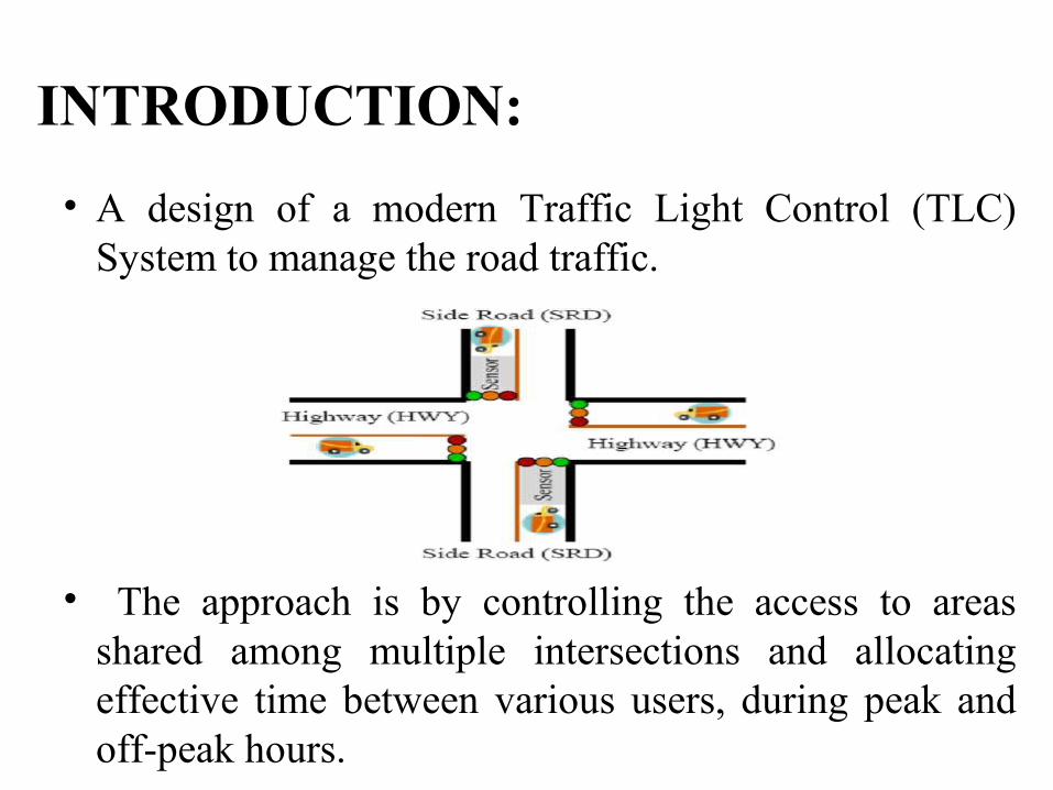
• A design of a modern Traffic Light Control (TLC) System to manage the road traffic.
• The approach is by controlling the access to areas shared among multiple intersections and allocating effective time between various users, during peak and off-peak hours.
INTRODUCTION:

• Intelligent Transportation Systems (ITS) applications for traffic signals – including communications systems, adaptive control systems, traffic responsive, real-time data collection and analysis, and maintenance
management systems.
• The heart of the system is a Finite State Machine (FSM) that directs the unit to light the main and side street lights at appropriate times for the specified time intervals.
VLSI
• Very-large-scale integration (VLSI) is the process of creating integrated circuits by combining transistors-based circuits into a single chip.
• A typical Hardware Description Language (HDL) to describe the digital systems.
HDL
TYPES OF HDL’S
• There are two types of HARDWARE DESCRIPTION LANGUAGES.
• VHDL [VHSIC HDL](Very High Speed Integrated Circuit Hardware Description Language).
• VERILOG HDL(verify logic hardware description language).

SOFTWARE USED:
XILINX 14.5
LANGUAGE USED:
Verilog HDL

THE STATE MACHINE:
•The Finite State Machine(FSM) responds to input signals and generate output and control signals needed to the system function.•Here we are using 2 FSM’s.•One is used to change states on every clock cycle and another is used to calculate what the next state should be based on current inputs and current state.
TYPES OF STATE MACHINES:
Mealy Machine.
Moore Machine.
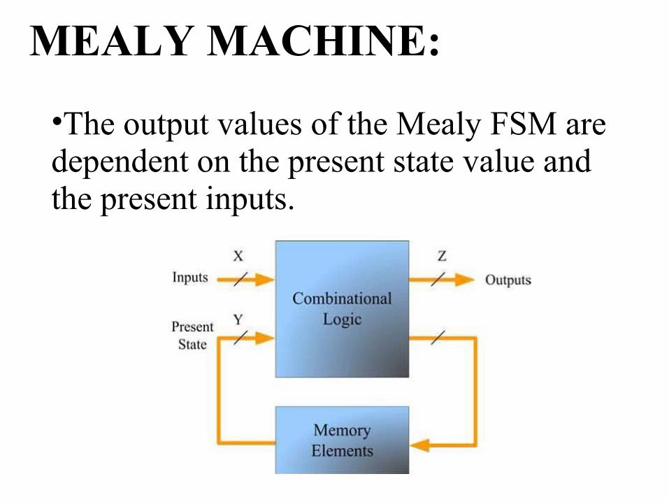
MEALY MACHINE:
•The output values of the Mealy FSM are dependent on the present state value and the present inputs.

MOORE MACHINE:•The output values of the Moore FSM are dependent only on its present state value and it is in contrast to the mealy machine.
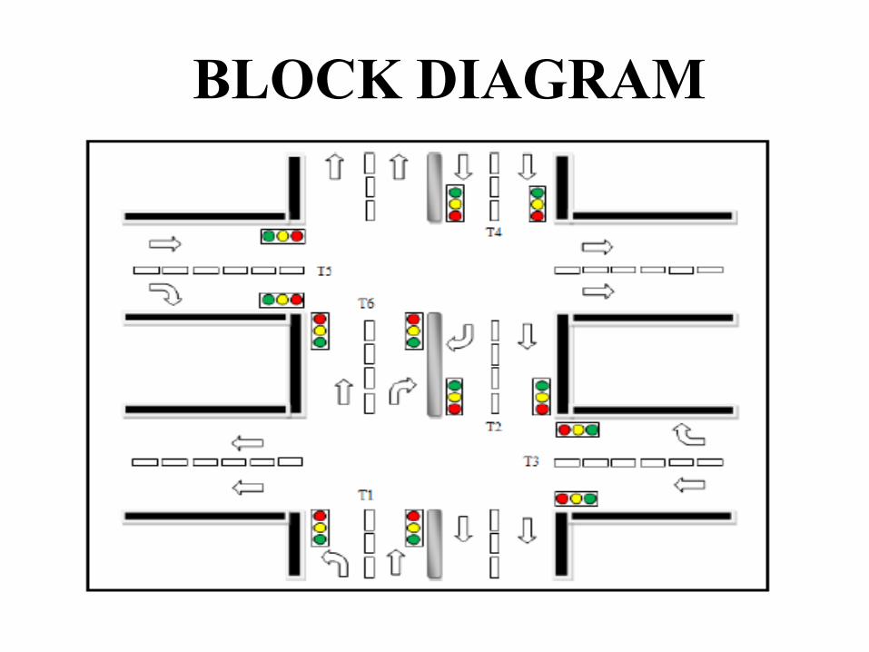
BLOCK DIAGRAM
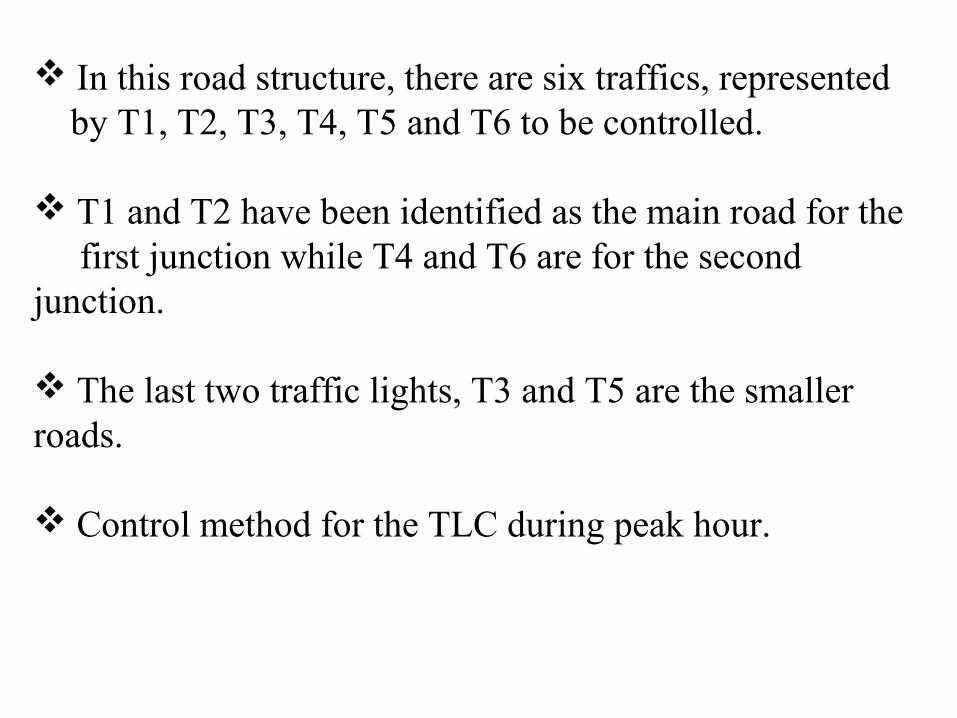
In this road structure, there are six traffics, represented by T1, T2, T3, T4, T5 and T6 to be controlled.
T1 and T2 have been identified as the main road for the first junction while T4 and T6 are for the second junction.
The last two traffic lights, T3 and T5 are the smaller roads.
Control method for the TLC during peak hour.
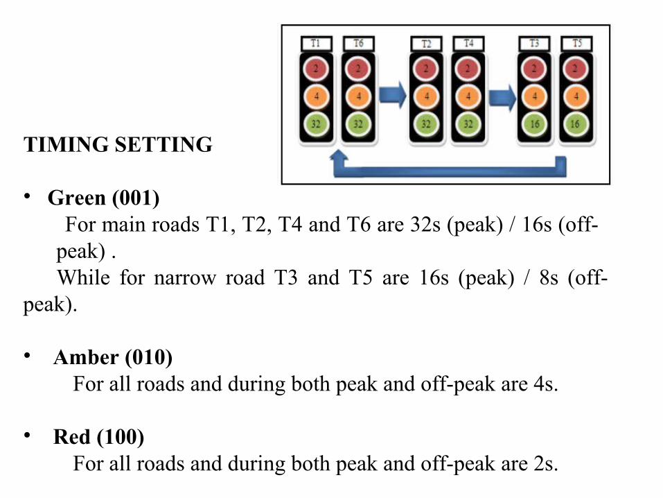
TIMING SETTING
• Green (001) For main roads T1, T2, T4 and T6 are 32s (peak) / 16s (off-
peak) .While for narrow road T3 and T5 are 16s (peak) / 8s (off-
peak).
• Amber (010) For all roads and during both peak and off-peak are 4s.
• Red (100) For all roads and during both peak and off-peak are 2s.

Verilog Model
The model consists of:
• CLOCK: System clock
• RESET: System reset
• PEAK: Represents peak hour (1) and off-peak hour (0)
• SENSOR1 and SENSOR2: Represent the two sensors used to detect the presence of car at the narrow road, T3 (Sensor1) and T5 (Sensor2).

RTL SCHEMATICS:

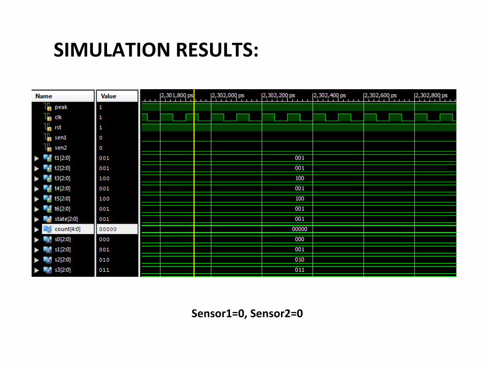
SIMULATION RESULTS:
Sensor1=0, Sensor2=0

Sensor1=0, Sensor2=1
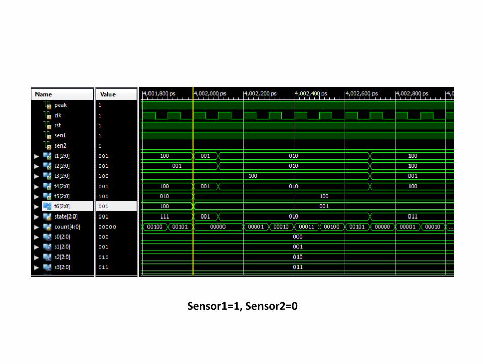
Sensor1=1, Sensor2=0

Sensor1=1, Sensor2=1

ADVANTAGES:
1. Low power consumption.2. Easy to implement.3. Speed of operation.

APPLICATIONS:
To control the traffic signals at any junction.

CONCLUSION: To design traffic light controller by using Verilog HDL.

THANK YOU

QUERIES