DESIGN OF FIXTURE FOR INK-DUCT ASSEMBLY
10
Research Paper E-ISSN NO : 2455-295X | VOLUME : 5 | ISSUE : 5 | MAY 2019 INTERNATIONAL EDUCATIONAL SCIENTIFIC RESEARCH JOURNAL 29 DESIGN OF FIXTURE FOR INK-DUCT ASSEMBLY PROF.S.V. LINGARAJU 1 1 PROFESSOR, DEPARTMENT OF MECHANICAL ENGINEERING TATYASAHEB KORE INSTITUTE OF ENGINEERING AND TECHNOLOGY, WARANANAGAR, KOLHAPUR, INDIA. ABSTRACT: This paper presents a fixture design for Ink-duct assembly. Fixture is required in various industries according to their application such as manufacturing fixture, assembly fixture, test fixture, welding fixture etc. Product design and development department design fixture according to dimensions required to fulfill our production target. In traditional assembly process with the machine required more time and it is critical and time consuming job. So holding a work piece in proper and align manner fixture is very necessary and important. Because of no. of parts required to assemble to the machine it is important to design assembly fixture for ink-duct assembly. Fixture reduces operation time and increases productivity and high quality of operation is possible. KEYWORDS: FIXTURE DESIGN, DESIGN FOR AUTOMATION, REDUCING TIME, INCREASING PRODUCTIVITY, LEAD SCREW. I. INRODUCTION The design of a fixture is a highly complex and intuitive process, which require knowledge. Fixture design plays an important role at the setup planning phase. Proper fixture design is crucial for developing product quality in different terms of accuracy, surface finish and precision of the machined parts. In existing machine the set-up is done manually, so the aim of this project is to replace manual process with fixture to save time for loading and unloading of component. Fixture provides the manufacturer to optimize operation time as well as process function ability. A fixture is a mechanism used in manufacturing to hold a work piece, position it correctly with respect to a machine tool, and support it during machining. Fixture is a device for locating, holding and supporting a work piece during a manufacturing operation. Fixtures are essential elements of production processes as they are required in most of the automated manufacturing, inspection, and assembly operations. Fixtures must correctly locate a work piece in a given orientation with respect to a cutting tool or measuring device. They are normally designed for a definite operation to process a specific work piece and are designed and manufactured individually. Widely used in manufacturing, fixtures have a direct impact upon product quality, productivity and cost. The design and manufacture of a fixture can take several days or even longer to complete when human experience in fixture design is utilized. And a good fixture design is often based on the designer’s experience, his understanding of the products, and a try-and-error process. Therefore, with the increasingly intense global competition which pushes every manufacturer in industry to make the best effort to sharpen its competitiveness by enhancing the product’s quality, squeezing the production costs and reducing the lead time. II. LITERATURE REVIEW Shailesh S.Pachbhai1, et al. [1], in machining fixtures, minimizing work piece deformation due to clamping and cutting forces is essential to maintain the machining accuracy. The various methodology used for clamping operation used in different application by various authors are reviewed in this paper. Fixture is required in various industries according to their application. This can be achieved by selecting the optimal location of fixture elements such as locators and clamps. The fixture set up for component is done manually. For that more cycle time required for loading and unloading the material. So, there is need to develop system which can help in improving productivity and time. Fixtures reduce operation time and increases productivity and high quality of operation is possible. U. Farhanaet al. [2] the need for improved productivity and reduced time to market has been increased significantly in manufacturing processes in recent decades. There are many factors that play a role in providing manufacturing processes with more productivity. One is the use of modular fixtures (MFs). MFs have brought many benefits to manufacturing industries including reduced costs and times of production. An MF can be defined as a complete system that consist different elements for effectively and securely holding the work piece in place for performing various machining operations. R Nagendra Babu et al. [3] The Over the past century, manufacturing has made considerable progress. New machine tools, high performance cutting tools, and modern manufacturing processes enable today's industries to
Transcript of DESIGN OF FIXTURE FOR INK-DUCT ASSEMBLY

Research Paper E-ISSN NO : 2455-295X | VOLUME : 5 | ISSUE : 5 | MAY 2019
I N T E R N A T I O N A L E D U C A T I O N A L S C I E N T I F I C R E S E A R C H J O U R N A L
29
DESIGN OF FIXTURE FOR INK-DUCT ASSEMBLY
PROF.S.V. LINGARAJU 1 1 PROFESSOR, DEPARTMENT OF MECHANICAL ENGINEERING TATYASAHEB KORE INSTITUTE OF ENGINEERING AND
TECHNOLOGY, WARANANAGAR, KOLHAPUR, INDIA.
ABSTRACT:
This paper presents a fixture design for Ink-duct assembly. Fixture is required in various industries according to their application such as manufacturing fixture, assembly fixture, test fixture, welding fixture etc. Product design and development department design fixture according to dimensions required to fulfill our production target. In traditional assembly process with the machine required more time and it is critical and time consuming job. So holding a work piece in proper and align manner fixture is very necessary and important. Because of no. of parts required to assemble to the machine it is important to design assembly fixture for ink-duct assembly. Fixture reduces operation time and increases productivity and high quality of operation is possible.
KEYWORDS: FIXTURE DESIGN, DESIGN FOR AUTOMATION, REDUCING TIME, INCREASING PRODUCTIVITY, LEAD SCREW.
I. INRODUCTION
The design of a fixture is a highly complex and intuitive process, which require knowledge. Fixture design plays an important role at the setup planning phase. Proper fixture design is crucial for developing product quality in different terms of accuracy, surface finish and precision of the machined parts. In existing machine the set-up is done manually, so the aim of this project is to replace manual process with fixture to save time for loading and unloading of component. Fixture provides the manufacturer to optimize operation time as well as process function ability.
A fixture is a mechanism used in manufacturing to hold a work piece, position it correctly with respect to a machine tool, and support it during machining. Fixture is a device for locating, holding and supporting a work piece during a manufacturing operation. Fixtures are essential elements of production processes as they are required in most of the automated manufacturing, inspection, and assembly operations. Fixtures must correctly locate a work piece in a given orientation with respect to a cutting tool or measuring device. They are normally designed for a definite operation to process a specific work piece and are designed and manufactured individually. Widely used in manufacturing, fixtures have a direct impact upon product quality, productivity and cost.
The design and manufacture of a fixture can take several days or even longer to complete when human experience in fixture design is utilized. And a good fixture design is often based on the designer’s experience, his understanding of the products, and a try-and-error process. Therefore, with the increasingly intense global competition which pushes every manufacturer in industry to make the best effort to sharpen its competitiveness by
enhancing the product’s quality, squeezing the production costs and reducing the lead time.
II. LITERATURE REVIEW
Shailesh S.Pachbhai1, et al. [1], in machining fixtures, minimizing work piece deformation due to clamping and cutting forces is essential to maintain the machining accuracy. The various methodology used for clamping operation used in different application by various authors are reviewed in this paper. Fixture is required in various industries according to their application. This can be achieved by selecting the optimal location of fixture elements such as locators and clamps. The fixture set up for component is done manually. For that more cycle time required for loading and unloading the material. So, there is need to develop system which can help in improving productivity and time. Fixtures reduce operation time and increases productivity and high quality of operation is possible.
U. Farhanaet al. [2] the need for improved productivity and reduced time to market has been increased significantly in manufacturing processes in recent decades. There are many factors that play a role in providing manufacturing processes with more productivity. One is the use of modular fixtures (MFs). MFs have brought many benefits to manufacturing industries including reduced costs and times of production. An MF can be defined as a complete system that consist different elements for effectively and securely holding the work piece in place for performing various machining operations.
R Nagendra Babu et al. [3] The Over the past century, manufacturing has made considerable progress. New machine tools, high performance cutting tools, and modern manufacturing processes enable today's industries to
Research Paper E-ISSN NO : 2455-295X | VOLUME : 5 | ISSUE : 5 | MAY 2019
I N T E R N A T I O N A L E D U C A T I O N A L S C I E N T I F I C R E S E A R C H J O U R N A L
30
make parts faster and better than ever before. Although work holding methods have also advanced considerably, the basic principles of clamping and locating are still the same. Jigs and fixtures form an important category of equipment that goes a long way in achieving productivity. A jig, however, guides the cutting tool. A fixture references the cutting tool. The differentiation between these types of work holders is in their relation to the cutting tool. The main objective of using jigs in an industry is to achieve the Interchangeable Part Concept, and these are mainly used where production of goods is on large scale. A fixture is a work holding device which only holds and positions the work, but does not in itself guide locate or position the cutting tool. The setting of the tool is done by machine adjustment and a setting block or by using slip gauges. A fixture is bolted or clamped to the machine table. It is usually heavy in construction.
V. R.Basha et al.[4] The fixtures have a direct impact upon product manufacturing quality, productivity and cost, so much attention has already been paid to the research fixture design and many achievements in this field have been reported. In this paper, a literature survey of fixture design and automation over the past decade is proposed. First, an introduction is given on the fixture applications in industry. Then, significant works done in the design field, including their approaches, requirements and working principles are discussed. Finally, some prospective research trends are also discussed.
Shivaji Mengawade, et al. [5] the design of a fixture is a highly complex and intuitive process, which require knowledge. Fixture design plays an important role at the setup planning phase. Proper fixture design is crucial for developing product quality in different terms of accuracy, surface finish and precision of the machined parts .In existing design the fixture set up is done manually, so the aim of this project is to replace with fixture to save time for loading and unloading of component. Fixture provides the manufacturer for flexibility in holding forces and to optimize design for machine operation as well as process function ability.
Shrikant.V.Peshatwar et al. [6] this paper present a fixture design system of eccentric shaft for ginning machine. Fixture is required in various industries according to their application. Designer design fixture according to dimension required by industry to fulfill our production tar gate. In traditional manufacturing process performing operation on eccentric shaft is critical. So holding a work piece in proper position during a manufacturing operation fixture is very necessary and important. Because the shaft is eccentric so for this requirement of manufacturing process Designer design proper fixture for eccentric shaft. Fixtures reduce operation time and increases productivity and high quality of operation is possible.
Hui Wang et al. [7]widely used in manufacturing, fixture have a direct impact upon product manufacturing quality, productivity and cost, so much attention has already been paid to the research of computer aided fixture design
(CAFD) and many achievements in this field have been reported. In this paper, a literature survey of computer aided fixture design and automation over the past decade is proposed. First, an introduction is given on the fixture application in industry. Then, significant works done in the CAFD field, including their approaches, requirements and working principle are discussed. Finally, some prospective research trends are also discussed.
R. Förstmannet al. [8] as product varieties rise and lifecycles shorten, development approaches need to be adapted. Current trends aiming to solve the dissonance of reduced time to market and increased product variety include agile methods. In this context not only product design processes need to be adapted but also development of production processes and manufacturing equipment. At the example of fixture design, this paper presents an approach which allows an agile provision as well as a reconfiguration of equipment. The solution presented consists of a fixture design concept consisting of design rules which allow implementation into a tool for automated fixture design.
S.Jack Hu [9] Fixtures are used to locate and hold work pieces during manufacturing. Because work piece surface errors and fixture set-up errors (called source errors) always exist, the fixture work piece will consequently have position and/or orientation errors (called resultant errors). In this paper, we develop a variational method for robust fixture configuration design to minimize work piece resultant errors due to source errors. We utilize both first-order and second-order work piece geometry information to deal with two types of source errors, i.e., infinitesimal errors and small errors. Using the proposed variational approach, other fundamental fixture design issues, such as deterministic locating and total fixturing, can be regarded as integral parts of the robust design. Closed-form analytical solutions are derived and numerical examples are shown. By employing the nonlinear programming technique, simulation software called RFixDesign is developed. This paper presents a new procedure for robust fixture configuration design that contributes especially to fixture designs where deformation is not influential.
P.T.Patel et al. [10] the purpose of this work is to convey the basic idea on the gear shifting fork and its fixtures for machining. A fixture is designed and built to hold, support and locate every component to ensure that each is drilled or machined with accuracy and manufactured individually. In machining fixtures, minimizing work piece deformation due to clamping and cutting forces is essential to maintain the machining accuracy. Tools required for the machining of fork is mentioned in this work along with the operations required for the machining of fork is also described here. This work also includes the basic about fixtures. The fixture set up for component is done manually and for that more cycle time is required for loading and unloading the material. So, there is need to develop system which can help in improving productivity and time. Fixtures reduces operation time and increases productivity and high quality

Research Paper E-ISSN NO : 2455-295X | VOLUME : 5 | ISSUE : 5 | MAY 2019
I N T E R N A T I O N A L E D U C A T I O N A L S C I E N T I F I C R E S E A R C H J O U R N A L
31
of operation is possible. The design of the geometric model of fork is also developed. The new fixture design is carried out by using modeling software and simulated on Analysis software.
III. PROBLEM DEFINITION
In “City-line paper printing machine”, there is problem related to fixture of Ink duct assembly. It is difficult to rotate roller manually and because of this it increases physical and mental stresses on worker.
IV. OBJECTIVES OF PROJECT
To design and manufacturing of mechanism to drive ink duct roller of city line paper printing machine.
V. METHODOLOGY
1. Discuss Problem of City line printing machine with
company.
2. Analyse the problem.
3. Study of research papers related to fixture design and
automation.
4. Make different solution.
5. Discuss solutions and select proper one.
6. Work on design of automation.
7. Make model of automation by using CREO/CATIA
software.
8. Making drawing by using Auto-CAD software.
9. Hand over the design details to company.
10. Manufacturing of the fixture as per design.
11. Testing of fixture.
12. Make project report.
VI. CONCEPTUAL DESIGN OF PROBLEM
FIG.1.PTC-CREO CONCEPTUAL DIAGRAM OF FIXTURE
VII. WORKING
Ink duct roller and motor shaft is connected with help of coupling and roller rotated with help of motor at
synchronised speed. For connecting ink duct roller and motor shaft, we required to reduce time and human effort. Also maintain proper distance for easy removal of roller.
VIII. CALCULATIONS
A. Motor Selection for Driving Ink Duct Roller
External diameter of roller = 110mm
Radius (b) = 55mm = 0.055m
Internal diameter of roller at middle = 92mm
Radius (a) = 46mm = 0.046m
Length of roller (L) = 1391mm =1.391m
Weight of roller = 30kg
Mass moment of Inertia
Ix = m (a2+b2)/2
= 30(0.0462+0.0552)/2
= 0.0771 Kg.m2
Iy = Iz = m (3a2+3b2+L)/12
= 30(3×0.0462 + 3×0.0552 + 1.3912)/12
= 4.87 kg. m2
Initial Velocity (ω0) = 0
Final Velocity (ω1) = 2𝜋𝑁
60 =
2𝜋 × 20
60 = 2.094 rad/s
Angular Acceleration (a) = (ω1-ω0)/t
= (2.094 - 0)/0.5
= 4.188 rad/s2
Torque = Iy × a = 4.87 × 4.188 = 20.39 N.m
Load Torque = Force × Radius = 300 × 0.055 = 16.5 N.m
Total Torque = (20.39 + 16.5) × 2 = 73.78 N.m … (Service Factor = 2)
Power required to drive the shaft
P = 2𝜋𝑁
60 =
2𝜋 × 20 ×73.78
60 = 154.52 watt
P = 154.52
746= 0.2094 HP ≅ 0.25 HP motor is required to drive
the roller.
B. Calculation of Base Plate for Motor Mounting
We have,
Weight of motor = 12 kg = 117.22 N ≅120 N
… (Dynaflux PMDC motor manufacturer catalogue)
Research Paper E-ISSN NO : 2455-295X | VOLUME : 5 | ISSUE : 5 | MAY 2019
I N T E R N A T I O N A L E D U C A T I O N A L S C I E N T I F I C R E S E A R C H J O U R N A L
32
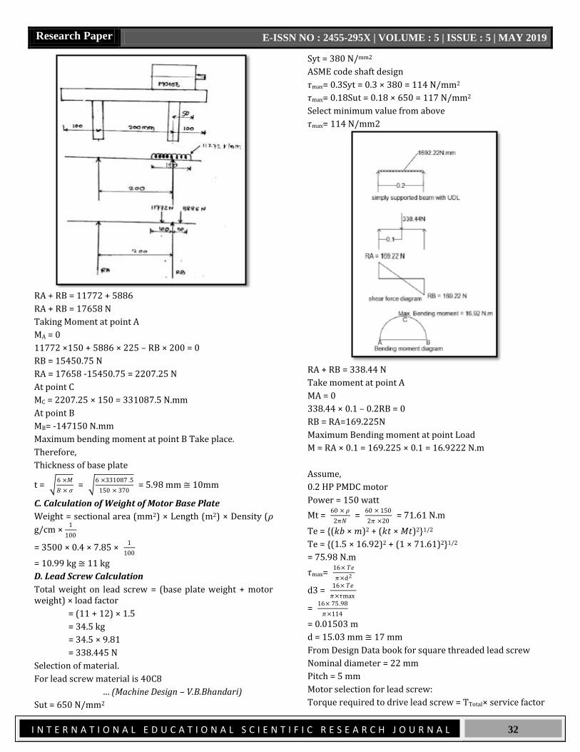
RA + RB = 11772 + 5886
RA + RB = 17658 N
Taking Moment at point A
MA = 0
11772 ×150 + 5886 × 225 – RB × 200 = 0
RB = 15450.75 N
RA = 17658 -15450.75 = 2207.25 N
At point C
MC = 2207.25 × 150 = 331087.5 N.mm
At point B
MB= -147150 N.mm
Maximum bending moment at point B Take place.
Therefore,
Thickness of base plate
t = 6 ×𝑀
𝐵 × 𝜍 =
6 ×331087 .5
150 × 370 = 5.98 mm ≅ 10mm
C. Calculation of Weight of Motor Base Plate
Weight = sectional area (mm2) × Length (m2) × Density (𝜌
g/cm × 1
100
= 3500 × 0.4 × 7.85 × 1
100
= 10.99 kg ≅ 11 kg
D. Lead Screw Calculation
Total weight on lead screw = (base plate weight + motor weight) × load factor
= (11 + 12) × 1.5
= 34.5 kg
= 34.5 × 9.81
= 338.445 N
Selection of material.
For lead screw material is 40C8
… (Machine Design – V.B.Bhandari)
Sut = 650 N/mm2
Syt = 380 N/mm2
ASME code shaft design
𝜏max= 0.3Syt = 0.3 × 380 = 114 N/mm2
𝜏max= 0.18Sut = 0.18 × 650 = 117 N/mm2
Select minimum value from above
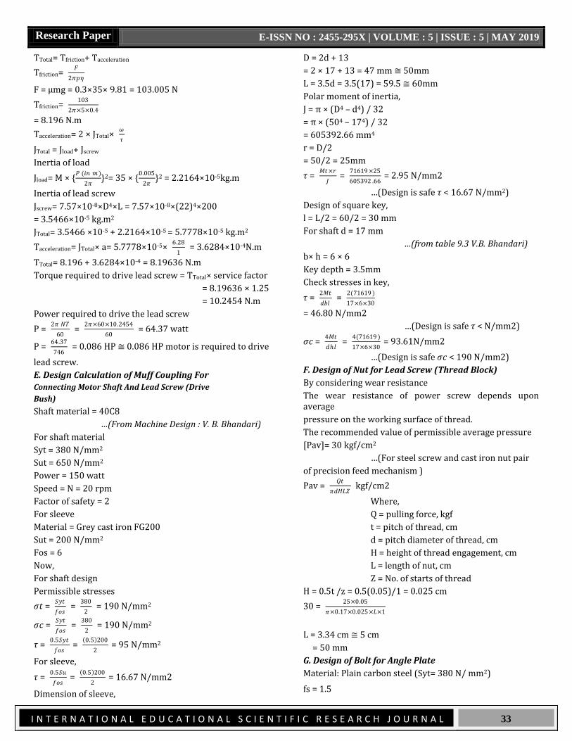
𝜏max= 114 N/mm2
RA + RB = 338.44 N
Take moment at point A
MA = 0
338.44 × 0.1 – 0.2RB = 0
RB = RA=169.225N
Maximum Bending moment at point Load
M = RA × 0.1 = 169.225 × 0.1 = 16.9222 N.m
Assume,
0.2 HP PMDC motor
Power = 150 watt
Mt = 60 × 𝜌
2𝜋𝑁 =
60 × 150
2𝜋 ×20 = 71.61 N.m
Te = {(𝑘𝑏 × 𝑚)2 + (𝑘𝑡 × 𝑀𝑡)2}1/2
Te = {(1.5 × 16.92)2 + (1 × 71.61)2}1/2
= 75.98 N.m
𝜏max= 16× 𝑇𝑒
𝜋×d2
d3 = 16× 𝑇𝑒
𝜋×τmax
= 16× 75.98
𝜋×114
= 0.01503 m
d = 15.03 mm ≅ 17 mm
From Design Data book for square threaded lead screw
Nominal diameter = 22 mm
Pitch = 5 mm
Motor selection for lead screw:
Torque required to drive lead screw = TTotal× service factor
Research Paper E-ISSN NO : 2455-295X | VOLUME : 5 | ISSUE : 5 | MAY 2019
I N T E R N A T I O N A L E D U C A T I O N A L S C I E N T I F I C R E S E A R C H J O U R N A L
33
TTotal= Tfriction+ Tacceleration
Tfriction= 𝐹
2𝜋𝑝𝜂
F = μmg = 0.3×35× 9.81 = 103.005 N
Tfriction= 103
2𝜋×5×0.4
= 8.196 N.m
Tacceleration= 2 × JTotal× 𝜔
𝜏
JTotal = Jload+ Jscrew
Inertia of load
Jload= M × {𝑃 (𝑖𝑛 𝑚)
2𝜋}2= 35 × {
0.005
2𝜋}2 = 2.2164×10⁻⁵kg.m
Inertia of lead screw
Jscrew= 7.57×10⁻⁸×D4×L = 7.57×10-8×(22)4×200
= 3.5466×10⁻⁵ kg.m2
JTotal= 3.5466 ×10⁻⁵ + 2.2164×10-5 = 5.7778×10⁻⁵ kg.m2
Tacceleration= JTotal× a= 5.7778×10-5× 6.28
1 = 3.6284×10⁻⁴N.m
TTotal= 8.196 + 3.6284×10-4 = 8.19636 N.m
Torque required to drive lead screw = TTotal× service factor
= 8.19636 × 1.25
= 10.2454 N.m
Power required to drive the lead screw
P = 2𝜋 𝑁𝑇
60 =
2𝜋×60×10.2454
60 = 64.37 watt
P = 64.37
746 = 0.086 HP ≅ 0.086 HP motor is required to drive
lead screw.
E. Design Calculation of Muff Coupling For
Connecting Motor Shaft And Lead Screw (Drive
Bush)
Shaft material = 40C8
…(From Machine Design : V. B. Bhandari)
For shaft material
Syt = 380 N/mm2
Sut = 650 N/mm2
Power = 150 watt
Speed = N = 20 rpm
Factor of safety = 2
For sleeve
Material = Grey cast iron FG200
Sut = 200 N/mm2
Fos = 6
Now,
For shaft design
Permissible stresses
𝜍𝑡 = 𝑆𝑦𝑡
𝑓𝑜𝑠 =
380
2 = 190 N/mm2
𝜍𝑐 = 𝑆𝑦𝑡
𝑓𝑜𝑠 =
380
2 = 190 N/mm2
𝜏 = 0.5𝑆𝑦𝑡
𝑓𝑜𝑠 =
0.5 200
2 = 95 N/mm2
For sleeve,
𝜏 = 0.5𝑆𝑢
𝑓𝑜𝑠 =
0.5 200
2 = 16.67 N/mm2
Dimension of sleeve,
D = 2d + 13
= 2 × 17 + 13 = 47 mm ≅ 50mm
L = 3.5d = 3.5(17) = 59.5 ≅ 60mm
Polar moment of inertia,
J = π × (D4 – d4) / 32
= π × (504 – 174) / 32
= 605392.66 mm4
r = D/2
= 50/2 = 25mm
𝜏 = 𝑀𝑡×𝑟
𝐽 =
71619 ×25
605392 .66 = 2.95 N/mm2
…(Design is safe 𝜏 < 16.67 N/mm2)
Design of square key,
l = L/2 = 60/2 = 30 mm
For shaft d = 17 mm
…(from table 9.3 V.B. Bhandari)
b× h = 6 × 6
Key depth = 3.5mm
Check stresses in key,
𝜏 = 2𝑀𝑡
𝑑𝑏𝑙 =
2(71619 )
17×6×30
= 46.80 N/mm2
…(Design is safe 𝜏 < N/mm2)
𝜍𝑐 = 4𝑀𝑡
𝑑ℎ𝑙 =
4(71619 )
17×6×30 = 93.61N/mm2
…(Design is safe 𝜍𝑐 < 190 N/mm2)
F. Design of Nut for Lead Screw (Thread Block)
By considering wear resistance
The wear resistance of power screw depends upon average
pressure on the working surface of thread.
The recommended value of permissible average pressure
[Pav]= 30 kgf/cm2
…(For steel screw and cast iron nut pair
of precision feed mechanism )
Pav = 𝑄𝑡
𝜋𝑑𝐻𝐿𝑍 kgf/cm2
Where,
Q = pulling force, kgf
t = pitch of thread, cm
d = pitch diameter of thread, cm
H = height of thread engagement, cm
L = length of nut, cm
Z = No. of starts of thread
H = 0.5t /z = 0.5(0.05)/1 = 0.025 cm
30 = 25×0.05
𝜋×0.17×0.025×𝐿×1
L = 3.34 cm ≅ 5 cm
= 50 mm
G. Design of Bolt for Angle Plate
Material: Plain carbon steel (Syt= 380 N/ mm2)
fs = 1.5

Research Paper E-ISSN NO : 2455-295X | VOLUME : 5 | ISSUE : 5 | MAY 2019
I N T E R N A T I O N A L E D U C A T I O N A L S C I E N T I F I C R E S E A R C H J O U R N A L
34
σt = Syt
fos =
380
2 = 253.33 N/ mm2
P = 32.37× 10³ N
e = 75.96 mm
P1’ = P2’ = 𝑃
𝑁𝑜 .𝑜𝑓 𝑏𝑜𝑙𝑡𝑠
= 32.37×10^3
4
= 8092.5 N
The direct shear stress in each bolt is given by,
𝜏 = P1’
𝐴 =
8092.5
𝐴
Tensile stress in bolt:
P1’= 𝑃𝑒𝐿1
2(𝐿12+𝑙22)
= (32.37×103 ×150×182.03
2×(182.032+75.96^2)
= 11359.08 N
σt = 11359 .08
A
Principal stress in bolts
σt= σt
2 +
6×𝑀
𝐵×σ =
σt
2 + τ ^2
σt= 5679.54
A +
11359 .08
2𝐴 ^2 +
8092.5
𝐴 ^2
σt = 9835.94
A
σt = 253.33 N/ mm2
Area = A = 38.82 mm2
From Bhandari book standard size of bolt is M12 selected
Bolt for guide block:
L = 150 mm, L1= 20mm, L2 = 95mm, L3= 170 mm, L4= 245mm
Sut = 380 N/ mm2
Fs = 1.5
P1 = CL1, P2= CL2, P3= CL3, P4= CL4
PL= 2P1L1+2P2L2+2P3L3+2P4L4
PL = 2(CL1)L1+2(CL2)L2+2(CL3)L3+2(CL4)L4
C= P
2(L12+L22+L32+L42)
The maximum force will be acts on bolt
P4= PLL 4
2(L12+L22+L32+L42)
P4= 38.25×10³ 150 (245)
2(202+92+1702+2452)
P4= 7148.03
P4 = A(σt) × max.
7143.03 =(253.33)
A= 28.21 mm2
From Bhandari book, table 7.1 M8 is standard size of bolt.
H. Design of Bolts for Motor Mounting Plate
P = 5076.67 N
e = 57.5 mm
σt = 253.33 N/ mm2
P1`= P2` = 5076 .67
4 N/ mm2
𝜏 = 1269.67
A N/ mm2
P1``= 𝑃𝑒𝐿1
2(L12+L22) =
5076 .67 57.5 (87.5)
2(87.52+12.52)
P1``= 1646.31 N
σt = 1646 .31
A
σt = σt
2 +
σt
2
2
+ τ ^2
σt = 1646 .31
2A +
1646 .31
2A
2
+ 1269.67
2
2
= 2336 .2
A
A = 9.50 mm2
From Bhandari book M8 standard size of bolt is selected.
IX. CONCEPTUAL MODELS
1. Design Concept No. 1
FIG.2 DESIGN CONCEPT NO.1
2. Design Concept No. 2:
FIG.3 DESIGN CONCEPT NO.2
Research Paper E-ISSN NO : 2455-295X | VOLUME : 5 | ISSUE : 5 | MAY 2019
I N T E R N A T I O N A L E D U C A T I O N A L S C I E N T I F I C R E S E A R C H J O U R N A L
35
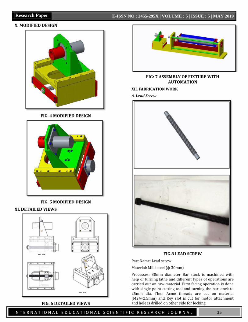
X. MODIFIED DESIGN
FIG. 4 MODIFIED DESIGN
FIG. 5 MODIFIED DESIGN
XI. DETAILED VIEWS
FIG. 6 DETAILED VIEWS
FIG: 7 ASSEMBLY OF FIXTURE WITH AUTOMATION
XII. FABRICATION WORK
A. Lead Screw
FIG.8 LEAD SCREW
Part Name: Lead screw
Material: Mild steel (ϕ 30mm)
Processes: 30mm diameter Bar stock is machined with help of turning lathe and different types of operations are carried out on raw material. First facing operation is done with single point cutting tool and turning the bar stock to 25mm dia. Then Acme threads are cut on material (M24×2.5mm) and Key slot is cut for motor attachment and hole is drilled on other side for locking.
Research Paper E-ISSN NO : 2455-295X | VOLUME : 5 | ISSUE : 5 | MAY 2019
I N T E R N A T I O N A L E D U C A T I O N A L S C I E N T I F I C R E S E A R C H J O U R N A L
36
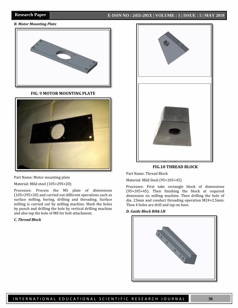
B. Motor Mounting Plate
FIG. 9 MOTOR MOUNTING PLATE
Part Name: Motor mounting plate
Material: Mild steel (105×295×20)
Processes: Process the MS plate of dimensions (105×295×20) and carried out different operations such as surface milling, boring, drilling and threading. Surface milling is carried out by milling machine. Mark the holes by punch and drilling the hole by vertical drilling machine and also tap the hole of M8 for bolt attachment.
C. Thread Block
FIG.10 THREAD BLOCK
Part Name: Thread Block
Material: Mild Steel (95×105×45)
Processes: First take rectangle block of dimensions (95×105×45). Then finishing the block at required dimension on milling machine. Then drilling the hole of dia. 23mm and conduct threading operation M24×2.5mm. Then 4 holes are drill and tap on base.
D. Guide Block RH& LH

Research Paper E-ISSN NO : 2455-295X | VOLUME : 5 | ISSUE : 5 | MAY 2019
I N T E R N A T I O N A L E D U C A T I O N A L S C I E N T I F I C R E S E A R C H J O U R N A L
37
FIG.11 GUIDE BLOCK RH& LH
Part Name: Guide Block RH & LH
Material: Mild Steel
Processes: Take rectangle block of dimension and milling is done on it as per drawing. Holes of dia (9mm) are drill and tap on L section.
E. Frame
FIG. 12 FRAME
Part Name: Frame
Material: Mild steel
Processes: Cutting plates of following dimensions as per drawing and drilled and tapped holes on plates. Then this plates are joined together with help of Arc welding process.
F. Angle Plate
FIG. 13 ANGLE PLATE
Part Name: Angle Plate
Material: Cast iron
Processes: Casting of part is done as per the dimensions given in drawing and then different types of machining and drilling is carried out on it. Then tapped the hole for bolting.
G. Drive Bush
FIG. 14 DRIVE BUSH

Research Paper E-ISSN NO : 2455-295X | VOLUME : 5 | ISSUE : 5 | MAY 2019
I N T E R N A T I O N A L E D U C A T I O N A L S C I E N T I F I C R E S E A R C H J O U R N A L
38
Part Name: Dive Bush
Material: Mild Steel
Processes: Stock material of ϕ75×80mm is turn to ϕ70 and different operations are carried out such as boring of ϕ40 by one side and drilled of ϕ 15 from another end. Slots are cut on both holes and hole of ϕ 10 & ϕ 15 are drilled in slot of ϕ 40 bore.
FIG. 15 MOTOR 1
Part Name: Motor 1
Specifications: PMDC motor
Manufacturer: Rotomag
Model: MG-4
Rpm: 100
FIG. 16 MOTOR 2
Part Name: Motor 2
Specifications: AC synchronous Motor
Manufacturer: Srijan control drives Pune
Torque: 10 kg-cm
Rpm: 60
REFERENCES
1. ShaileshS.Pachbhai et al.A Review on Design of Fixtures International Journal of Engineering Research and General Science Volume 2, Issue 2, Feb-Mar 2014 ISSN 2091-2730.
2. U. Farhanet al. Design of modular fixtures using a 3D-modelling approach 19th International Congress on Modelling and Simulation, Perth, Australia, 12–16 December 2011.
3. R NAGENDRA BABU Et al. Design and Analysis of Jig & Fixture ISSN: 2395-0463 Volume 03 Issue 03 Special Issue.
4. V. R.Basha et al. An Advanced Exploration on Fixture Design Int. Journal of Engineering Research and Applications ISSN: 2248-9622, Vol. 5, Issue 6, (Part -3) June 2015, pp.30-33.
5. ShivajiMengawade et al.A Review on Design and Analysis of Work Holding Fixture International Journal of Engineering Research and General Science Volume 4, Issue 2, March-April, 2016ISSN 2091-2730 136.
6. Shrikant.V.Peshatwaretal.Design and Development of Fixture for eccentric shaftISSN: 2248-9622 www.ijera.com Vol. 3, Issue 1, January -February 2013, pp.1591-1596.
7. Hui Wang et al. Computer aided fixture design: Recent research and trends computer-aided design 42(2010) 1085-1094.
8. R. Förstmann et al.Design for Automation: The Rapid Fixture Approach27th International Conference on Flexible Automation and Intelligent Manufacturing, FAIM2017, 27-30 June 2017, Modena, Italy.
9. S.JackHuetal.AVariational Method of Robust Fixture Configuration Design for 3-D Work piecesDepartment of Mechanical Engineering and Applied Mechanics, The University of Michigan, Ann Arbor, Ml 48109.
10. P.T.Patel et al. Designing a Fixture for Machining Gear Shifting ForkIJEDR | Volume 3, Issue 3 | ISSN: 2321-9939.