DESIGN OF END CONNECTORS FOR A TURNBUCKLE …ijaerd.com/papers/finished_papers/DESIGN OF END...
10
International Journal of Advance Engineering and Research Development Volume 3, Issue 2, February -2016 @IJAERD-2016, All rights Reserved 21 Scientific Journal of Impact Factor (SJIF): 3.134 e-ISSN (O): 2348-4470 p-ISSN (P): 2348-6406 DESIGN OF END CONNECTORS FOR A TURNBUCKLE IN ORDER TO SELECT MATERIALS UNDER DIFFERENT TENSILE LOADS Prof. Nitinchandra R Patel 1 , Patel Kishan B 2 , Thakrar Bhargav M 3 , Bharvad Vinod G 4 , Vaghela Rajesh D 5 12345 Department of Mechanical Engineering, G. H. Patel College of Engg and Technology, V.V.Nagar, Gujarat, India. 1 [email protected] --------------------------------------------------------------------------------------------------------------------------------------------------- Abstract — A Turn-Buckle is a device for adjusting tension as well as length of ropes, cables, tie rods and other tensioning system. It consists of two threaded ends, one with a left hand thread and other one is right hand thread. The end connections are required to fulfill the working in various applications. This project comprises of studies of adequate design calculation for stresses acting on threaded rod and at end connections. We have taken different size of rod dimension along with step loads of ends like eye end, hook end and jaw end. Different ends are subjected to tensile loading utilized in different applications and hence stresses are generated. Now for safe design of whole assembly stresses are analyzed and compared with standard selected materials. Here, the attempt is done to select better material in context with stress generation and material costing. For proper selection of material number of loads are taken with minimum incremental steps in selected range. A Matlab programming is done to solve such kind of design having number of iterations. According to design formulation, solid modeling is done for turnbuckle, end connections and assembled them. For convince in calculation, we have taken uniform m material for whole the assembly. After solid modeling, assemblies are analyses in order to find stresses induced. The Ansys results are for supporting the analytical values. . ---------------------------------------------------------------------------------------------------------------------------------------------------- Keywords- Coupler Nut, End connectors, tensile stress, Shear stress, Deformation, Solid Modeling I. INTRODUCTION Turnbuckle is a coupling with internal screw threads used to connect two rods, lengths of ship's rigging, lashing etc. lengthwise or to regulate their length or tension. The principles of the operation for a turnbuckle is to have the screw operating clockwise and counter clockwise to close the steel products or barrels. Turnbuckle can also be custom designed for particular needs of industry. They are more commonly made of steel but can be forged in iron as well. The purpose of the strong metal forged steel or iron turnbuckles is to pull tons of weight safely and surely. The turnbuckles are adjusted until the barrel is closed and the constraint tightly compressed. Turnbuckles are designed by releasing tension in a cable without adding unbearable stress onto ends of the cables particular attachment. They have high load carrying capacity and compact size. The main advantage of turnbuckle is the adjusting of tension and length just by rotating the coupler without much effort. Turnbuckle is one of the most essential and life saving product manufactured globally today. If we want to increase the range of load carrying capacity of turnbuckle, then material cost would be increase and ultimately, the cost of turnbuckle would increase. Yielding of the loop or one of the ringbolts will release the tensile forces in the system and could make operation unsafe. Fatigue fracture of the loop or one of the ringbolts could at any of the points of stress concentration in the turnbuckle assembly. Fracture of loop or one of the ringbolts could take place as a result of excessive loading of the system or as a result of impact loading if material lose their toughness in service. II. DESIGN FORMULATION FOR TURN BUCKLE Fig. 1 Turn Buckle or Coupler Nut 2.1 Diameter of tie rod (d c ): To design a threaded section, design load is taken as 1.25 the normal load.
Transcript of DESIGN OF END CONNECTORS FOR A TURNBUCKLE …ijaerd.com/papers/finished_papers/DESIGN OF END...

International Journal of Advance Engineering and Research Development
Volume 3, Issue 2, February -2016
@IJAERD-2016, All rights Reserved 21
Scientific Journal of Impact Factor (SJIF): 3.134 e-ISSN (O): 2348-4470 p-ISSN (P): 2348-6406
DESIGN OF END CONNECTORS FOR A TURNBUCKLE IN ORDER TO
SELECT MATERIALS UNDER DIFFERENT TENSILE LOADS Prof. Nitinchandra R Patel
1, Patel Kishan B
2, Thakrar Bhargav M
3, Bharvad Vinod G
4, Vaghela Rajesh D
5
12345Department of Mechanical Engineering, G. H. Patel College of Engg and Technology, V.V.Nagar, Gujarat, India.
----------------------------------------------------------------------------------------------------------------------------- ----------------------
Abstract — A Turn-Buckle is a device for adjusting tension as well as length of ropes, cables, tie rods and other
tensioning system. It consists of two threaded ends, one with a left hand thread and other one is right hand thread. The end
connections are required to fulfill the working in various applications. This project comprises of studies of adequate
design calculation for stresses acting on threaded rod and at end connections. We have taken different size of rod
dimension along with step loads of ends like eye end, hook end and jaw end. Different ends are subjected to tensile
loading utilized in different applications and hence stresses are generated. Now for safe design of whole assembly stresses
are analyzed and compared with standard selected materials. Here, the attempt is done to select better material in context
with stress generation and material costing. For proper selection of material number of loads are taken with minimum
incremental steps in selected range. A Matlab programming is done to solve such kind of design having number of
iterations. According to design formulation, solid modeling is done for turnbuckle, end connections and assembled them.
For convince in calculation, we have taken uniform m material for whole the assembly. After solid modeling, assemblies
are analyses in order to find stresses induced. The Ansys results are for supporting the analytical values. .
----------------------------------------------------------------------------------------------------------------------------- -----------------------
Keywords- Coupler Nut, End connectors, tensile stress, Shear stress, Deformation, Solid Modeling
I. INTRODUCTION Turnbuckle is a coupling with internal screw threads used to connect two rods, lengths of ship's rigging, lashing etc.
lengthwise or to regulate their length or tension. The principles of the operation for a turnbuckle is to have the screw
operating clockwise and counter clockwise to close the steel products or barrels. Turnbuckle can also be custom designed
for particular needs of industry. They are more commonly made of steel but can be forged in iron as well. The purpose of
the strong metal forged steel or iron turnbuckles is to pull tons of weight safely and surely. The turnbuckles are adjusted
until the barrel is closed and the constraint tightly compressed. Turnbuckles are designed by releasing tension in a cable
without adding unbearable stress onto ends of the cables particular attachment. They have high load carrying capacity and
compact size. The main advantage of turnbuckle is the adjusting of tension and length just by rotating the coupler without
much effort. Turnbuckle is one of the most essential and life saving product manufactured globally today.
If we want to increase the range of load carrying capacity of turnbuckle, then material cost would be increase and
ultimately, the cost of turnbuckle would increase. Yielding of the loop or one of the ringbolts will release the tensile forces
in the system and could make operation unsafe. Fatigue fracture of the loop or one of the ringbolts could at any of the
points of stress concentration in the turnbuckle assembly. Fracture of loop or one of the ringbolts could take place as a
result of excessive loading of the system or as a result of impact loading if material lose their toughness in service.
II. DESIGN FORMULATION FOR TURN BUCKLE
Fig. 1 Turn Buckle or Coupler Nut
2.1 Diameter of tie rod (dc):
To design a threaded section, design load is taken as 1.25 the normal load.

International Journal of Advance Engineering and Research Development (IJAERD)
Volume 3, Issue 2, February -2016, e-ISSN: 2348 - 4470, print-ISSN: 2348-6406
@IJAERD-2016, All rights Reserved 22
Direct tensile load Pd =1.25P
By considering the tearing of the thread of the rods at their roots.
Tensile stress σt =
The nominal diameter can be selected from ISO matric screw threads table, do =
2.2 Length of coupler nut (l):
Consider the direct shearing of the thread at the root of coupler nut and screw
a) The direct shear stress induced in screw thread
τs =
b) The direct shear stress induced in nut
τn =
c) Check of crushing of thread
Pd = (
2.3 Outside diameter of coupler nut (D)
The outside diameter of the coupler nut may be obtained by considering permissible tensile stress for the material of
coupler nut. We know that,
σt =
The actual practice, the diameter of the coupler nut D is taken from 1.25do to 1.5do., D is taken as , D=1.25do
2.4 Outside diameter of coupler (D2) The outside diameter of the coupler is obtained by considering permissible tensile stress. In actual practice, the outside
diameter of the coupler D2 is taken as 1.5do to 1.7do. So D2 = 1.5do
2.5 Length of coupler (Ln)
Ln = 6do
2.6 Thickness of coupler (t)
t =0.75do
2.7 Thickness of coupler nut (t1) t1 =0.5do
III. DESIGN FORMULATION FOR END CONNECTORS
3.1 Design of Jaw end
3.1.1 Rod in tension
Considering the rod is subjected to a direct tensile stress.
σt =
Fig. 2 Jaw End
3.1.2 Pin in shear
Due to direct tensile strength, the single eye is subjected to double shear. So, shear stress is,
3.1.3 Pin in Bending Assume there is no clearance or slack but in actual, pin is loose in forks to permit angular
moment of one with respect to other, so it is subjected to bending moment in addition to
shear, considering uniformly distributed load along the portion of pin. So, bending moment is,
International Journal of Advance Engineering and Research Development (IJAERD)
Volume 3, Issue 2, February -2016, e-ISSN: 2348 - 4470, print-ISSN: 2348-6406
@IJAERD-2016, All rights Reserved 23
3.2 Design of Eye End
[1] Tensile stress, σt =
[2] Shear stress, τ = 1.75σt
Fig. 3 Eye End
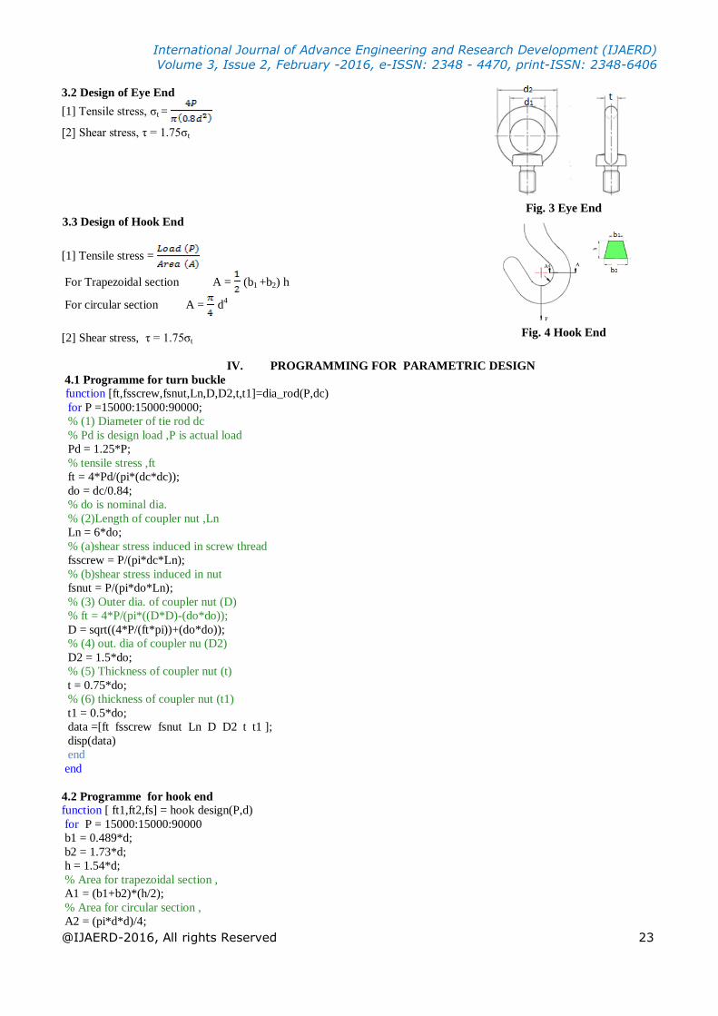
3.3 Design of Hook End
[1] Tensile stress =
For Trapezoidal section A = (b1 +b2) h
For circular section A = d4
[2] Shear stress, τ = 1.75σt
Fig. 4 Hook End
IV. PROGRAMMING FOR PARAMETRIC DESIGN
4.1 Programme for turn buckle
function [ft,fsscrew,fsnut,Ln,D,D2,t,t1]=dia_rod(P,dc)
for P =15000:15000:90000;
% (1) Diameter of tie rod dc
% Pd is design load ,P is actual load
Pd = 1.25*P;
% tensile stress ,ft
ft = 4*Pd/(pi*(dc*dc));
do = dc/0.84;
% do is nominal dia.
% (2)Length of coupler nut ,Ln
Ln = 6*do;
% (a)shear stress induced in screw thread
fsscrew = P/(pi*dc*Ln);
% (b)shear stress induced in nut
fsnut = P/(pi*do*Ln);
% (3) Outer dia. of coupler nut (D)
% ft = 4*P/(pi*((D*D)-(do*do));
D = sqrt((4*P/(ft*pi))+(do*do));
% (4) out. dia of coupler nu (D2)
D2 = 1.5*do;
% (5) Thickness of coupler nut (t)
t = 0.75*do;
% (6) thickness of coupler nut (t1)
t1 = 0.5*do;
data =[ft fsscrew fsnut Ln D D2 t t1 ];
disp(data)
end
end
4.2 Programme for hook end
function [ ft1,ft2,fs] = hook design(P,d)
for P = 15000:15000:90000
b1 = 0.489*d;
b2 = 1.73*d;
h = 1.54*d;
% Area for trapezoidal section ,
A1 = (b1+b2)*(h/2);
% Area for circular section ,
A2 = (pi*d*d)/4;
International Journal of Advance Engineering and Research Development (IJAERD)
Volume 3, Issue 2, February -2016, e-ISSN: 2348 - 4470, print-ISSN: 2348-6406
@IJAERD-2016, All rights Reserved 24
% (1) Tensile stress
% ft = load(P)/Area(A)
% ft1 is tensile stress for trapezoidal c/s
% ft2 is tensile stress for circular c/s
ft1 = P/A1;
ft2 = P/A2;
% (2 shear stress .
fs = 1.75*ft1;
data = [ft1 ft2 fs];
disp(data)
end
end
4.3 Programme for eye end
function [ ft,fs ] = eyedesign(P,d)
for P = 15000:15000:90000
% (1) Tensile stress
ft = (4*P)/(pi*(0.8*d)^2);
% (2) shear stress
fs = 1.75*ft;
data = [ft fs];
disp(data)
end
end
4.4 Programme for jaw end
function [ ft,fs,fb ] = jawdesign(P,d)
for P = 15000:15000:90000;
% (1) Rod in tension ,
% tensile stress
ft = 4*P/(pi*d*d);
% (2) Pin in shear ,
% shear stress
fs = 2*P/(pi*d*d);
% (3) Pin in bending ,
% bending stress
fb = (4*P*1.2*d)/(pi*d*d*d);
data = [ft fs fb];
disp(data)
end
end
V. RESULT AND DISCUSSION
5.1 Parametric Calculation of Turnbuckle
In this work, We have done analytical design manually by taking rod diameter of coupler nut with variation in load from 5
kN to 90 kN in step increment of 15 kN. For each selected diameter of rod, parameters of turnbuckle and end connections
are calculated. Here, rod diameter is taken like 10 mm, 30 mm and 60 mm, according to type of duty load (low, medium
and heavy). In design calculation, stresses which are responsible for failure are calculated. Such values are compared with
standard working values of materials. We have taken standard materials which are used widely for manufacturing of
turnbuckle. For simplicity in comparison, factor of safety is taken 4 for whole calculation. Working value of materials is
found from standard ultimate values of material. In context with material, we have taken following material.
Table No 1. Materials and Tesile and Shear stress values

International Journal of Advance Engineering and Research Development (IJAERD)
Volume 3, Issue 2, February -2016, e-ISSN: 2348 - 4470, print-ISSN: 2348-6406
@IJAERD-2016, All rights Reserved 25
First, analytical design is done manually
to calculate stresses induced in rod and
other parameters of component. A
Matlab programming is used to check all
iterative steps in calculation. Along with
the turnbuckle, the end connections are
also checked by applying the define
loads and induced stresses are found.
Stresses induced in threaded rods as well
as in the end are compared with standard
working value of define materials.
Which material is suitable for particular
load as well as base on cost, the better
material is selected.
Table No 2. Calculated parameter in design
5.2Parameteric Calculation of End Connections
The different ends have induced stresses like Jaw, eye and hook ends are subjected to tensile loading and hence a pin of
Jaw end fails in shear and bending, While eye and hook end fails in shear. So in order to find induced stresses, load is
varied from 5KN to 90KN with incremental step of 15KN. Also same loading application is used by taking define rod
diameters like 10mm, 30mm and 60mm. The said is calculated by programming and summarized as given below.
Table No 3. Calculated parameters of Eye Table No 4. Calculated parameters of Hook and Jaw
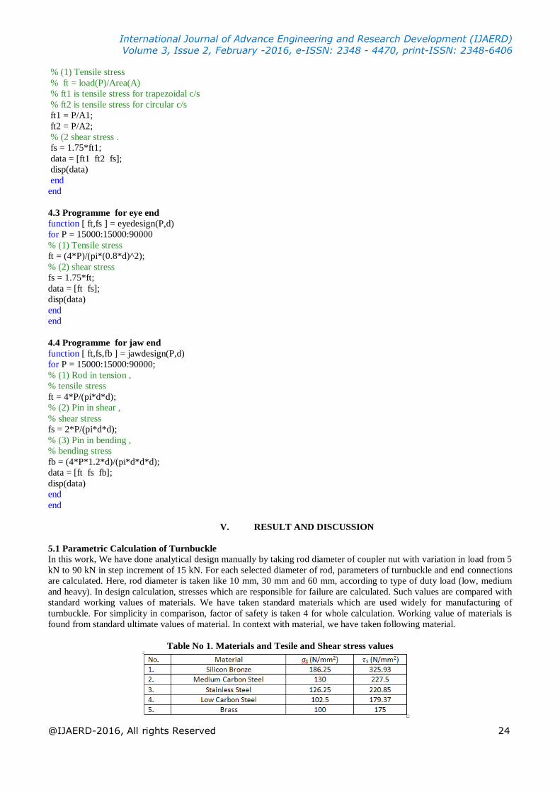
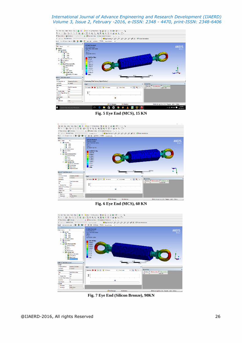
5.3 Stress analysis in Ansys:
Here ,We have done stress analysis for different types of ends of turnbuckles like eye , hook and jaw end .In that we have
applied tensile force at ends and checked value of Tensile stress, shear stress and deformation by applying varying load
such as 15 kN,60 kN,90 kN for different material such as silicon bronze , medium carbon steel and low carbon steel of 30
mm diameter of coupler nut. We observed that, In the application of tensile stress, Eye end is preferable and silicone
bronze is better from group of materials available for manufacturing of turnbuckle and ends.
International Journal of Advance Engineering and Research Development (IJAERD)
Volume 3, Issue 2, February -2016, e-ISSN: 2348 - 4470, print-ISSN: 2348-6406
@IJAERD-2016, All rights Reserved 26
Fig. 5 Eye End (MCS), 15 KN
Fig. 6 Eye End (MCS), 60 KN
Fig. 7 Eye End (Silicon Bronze), 90KN

International Journal of Advance Engineering and Research Development (IJAERD)
Volume 3, Issue 2, February -2016, e-ISSN: 2348 - 4470, print-ISSN: 2348-6406
@IJAERD-2016, All rights Reserved 27
Fig.8 Jaw End(MCS), 15KN
Fig.9 Jaw End (MCD) 60KN
Fig.10 Jaw End (Silicon Bronze), 90KN

International Journal of Advance Engineering and Research Development (IJAERD)
Volume 3, Issue 2, February -2016, e-ISSN: 2348 - 4470, print-ISSN: 2348-6406
@IJAERD-2016, All rights Reserved 28
Fig.11 Hook End (MCS), 15KN
Fig. 12 Hook End (MCS), 60KN
Fig.13 Hook End (Silicon Bronze), 90KN

International Journal of Advance Engineering and Research Development (IJAERD)
Volume 3, Issue 2, February -2016, e-ISSN: 2348 - 4470, print-ISSN: 2348-6406
@IJAERD-2016, All rights Reserved 29
CONCLUSION Here, from analytical and graphical analysis for turnbuckle, it shows that for 10 mm rod diameter, Silicon Bronze is
applicable at 5 kN load. Other materials like Medium Carbon Steel and Stainless Steel are alternatives. For 30 mm
diameter, Silicone Bronze, Medium Carbon Steel and Stainless Steel are applicable under 5 kN, 15 kN, 30 kN, 45 kN load.
For 60 mm diameter, all materials are applicable from 5 kN to 90 kN load.
If we consider stress analysis in End connections, in Eye failure due to shear is significant than tensile. In Hook, failure
due to shear is higher than tensile while in Jaw, failure due to bending is noticeable. In Eye,from Silicon Bronze, Medium
Carbon Steel and Stainless Steel are applicable for 10 mm and 30 mm rod diameter. While for 60 mm diameter, all
materials are applicable. For Hook, Silicon Bronze, Medium Carbon Steel and Stainless Steel are applicable for 10 mm
diameter up to 15 kN load while for 30 mm and 60 mm diameter, all materials are applicable for all selected loads. For
Jaw, for 10 mm diameter, all materials are applicable for only 5 kN load, for 30 mm, they are preferable from 5 kN to 60
kN load and 60 mm diameter, all materials are applicable for 5 kN to 90kN load.
Ultimately, it is concluded that, for lesser diameter, Silicon Bronze gives better performance while for larger diameter,
Medium Carbon Steel and Stainless Steel are better option. As far as the cost is concerned, Silicon Bronze is costlier than
other materials and Medium Carbon Steel and Stainless Steel are less costlier and easily available for manufacturing of
Turnbuckle. Hence, the later materials are most utilized in the application.
ACKNOWLEDGEMENT
We would like to express our sincere thanks and gratitude to our research guide Prof. Nitinchandra R. Patel for devoting
much of his precious & valuable time during the entire work & for offering numerous suggestions and encouragement thus
making the same possible.
We would like to thank other faculties of Department of Mechanical Engineering of G. H. Patel College of Engineering
& Technology for giving us all the guidance required during the whole work. They have been source of inspiration &
motivating for us.
We are also very thankful to all members of library for their co-operation and invaluable support.
PATEL KISHAN B.
THAKRAR BHARGAV M.
BHARVAD VINOD G.
VAGHELA RAJES D.
REFERENCES
[1] R. S. Khurmi and J. K. Gupta (2013), “Machine Design”, S. Chand Publication, Page no. 462, Section 12.16
[2] Dr. D. Padmanaban and Dr. M. Aruna, “Design Data (Data Book of Engineer )”, Compiled by PSG College of
Technology, Published by Kalaikathir Achchagam
[3] V. B. Bhandari, “Design of Machine Element”, McGraw Hill Education (india) Private Limited, New Delhi, Section 2
(page no.21) and Section 5 (page no. 141).
[4] Nitinchandra R Patel, S dalwadi, V Thakor, M Bamaniya, “Design of toggle jack considering material selection of
screw-nut combination”, IJIRSET, Vol 2, Issue 5, 2013, pp 1748-56.
[5] Nitinchandra R Patel, D B Rokad, A V Vekariya, P J Chauhan, “Consideration of material alternatives in enhancement
to get unique solution in design of screw jack”, IJEIT, Vol 3, Issue 2, 2014, pp 464-72.

International Journal of Advance Engineering and Research Development (IJAERD)
Volume 3, Issue 2, February -2016, e-ISSN: 2348 - 4470, print-ISSN: 2348-6406
@IJAERD-2016, All rights Reserved 30
AUTHORS’ BIOGRAPHY
Prof. Nitinchandra R. Patel is an Assistant Professor in Mechanical Engineering Department of
G. H. Patel College of Engineering & Technology, Vallabh Vidyanagar, Gujarat, India. He completed
Master degree in Machine Design in 2004 from Sardar Patel University, Vallabh Vidyanagar and
Bachelor degree in Mechanical Engineering in 1997 from B.V.M. Engineering College, Sardar Patel
University. He has 5 Years Industrial and 14 years teaching experience. He has presented 2 technical
research papers in International conferences and published 12 technical research papers in different
International journals. He reviewed a book published by Tata McGraw Hill in 2012. He is a
Member of Institute of Engineers (I) and Life member of ISTE. He is a reviewer in Editorial board
of International Journal of Advance Engineering and Research Development (IJAERD) [ISSN:
2348 – 6406] , a member in Editorial board of International Journal of Application or Innovation in
Engineering & Management (IJAIEM) [ISSN: 2319 – 4847] and in Editorial and review board of
International Journal of Research in Advanced Technology (IJRAT) [e-ISSN: 2321–9637]. He is
also recognized as a Chartered Engineer by Institute of Engineers (I) in Mechanical Engineering
Division in 2012.
Thakrar Bhargav Mayurbhai is a final year BE student of Mechanical Engineering Department
of G H Patel college of Engineering & Technology, V. V. Nagar
Patel Kishankumar Bharatbhai is a final year BE student of Mechanical Engineering Department
of G H Patel college of Engineering & Technology, V.V. Nagar
Vaghela Rajeshkumar Devashibhai is a final year BE student of Mechanical Engineering
Department of G H Patel college of Engineering & Technology, V.V. Nagar
Bharvad Vinod Gagubhai is a final year BE student of Mechanical Engineering Department of
G H Patel college of Engineering & Technology, V.V. Nagar