Design of Corrugated Metal Box Culvertsonlinepubs.trb.org/Onlinepubs/trr/1985/1008/1008-005.pdf ·...
9
Transportation Research Record 1008 33 Design of Corrugated Metal Box Culverts J. M. DUNCAN, R. B. SEED, and R. H. DRA WSKY ABSTRACT Corrugated metal box culverts provide large cross-sectional areas for water conveyance where vertical clearance is limited. Because they have nearly flat crowns and large widths compared with their heights, they behave differently from conventional metal culverts, and different methods are required for their design. The design procedure presented is based on field experience, finite- element analyses, and instrumented load tests on box culverts. The procedure encompasses bending moments in the crown and haunch sections due to backfill and traffic loads, design of portland cement concrete relieving slabs for con- ditions where cover depth is severely limited, recommended load factors for de- sign, and deflections in service for metal box culverts with spans as large as 26 ft. Corrugated metal box culverts were developed to meet a need for structures with large cross-sectional areas for water conveyance at sites with limited vertical clearance. Because of their great widths compared with their heights, box culverts are well suited to these conditions, as shown by the typical box culvert shapes in Figure 1. Rise= 2 1 -6 11 Span = 8' - 9" Rise = 6 1 -2 11 Span= 25'-2" Rise = 10'-2" Span =25'-5" R' se ..: 7' .. 2" Spon • il' • 4" FIGURE 1 Aluminum box culvert shapes. Because they have distinctly different shapes from conventional metal culverts, it would be antic- ipated that traditional design procedures, based largely on experience and applicable to culverts that carry a major portion of their loads through arch action, would not be applicable to structures with large-radius crown sections and straight sides as shown in Figure 1. The first corrugated metal box culverts, which were produced by using ribbed aluminum structural plate, were built in 1975. The design of these structures was completely empirical, relying on field load tests to establish acceptable structural plate thicknesses and rib spacings. Within 3 years a considerable number of box culverts had been con- structed, and demand for additional sizes increased to a point where completely empirical design proce- dures were no longer appropriate. In 1978 a study was undertaken at the University of California to develop rational designs for alumi- num box culvert structures. The first phase of these studies was a program of finite-element soil-struc- ture interaction analyses to evaluate the bending moments and axial forces in box culvert structures under loads imposed by backfill and live loads. Ex- perimental studies were also conducted to evaluate the stiffness and bending moment capacity of alumi- num structural plate with stiffener ribs bolted to one or both sides. In 1980 additional finite-element analyses were performed to assess the behavior of box culverts with spans up to 26 ft. In 1981 full- scale loading tests were performed on an instru- mented box culvert structure to provide a basis for detailed comparison of design calculations and mea- sured behavior. In 1984 additional finite-element analyses were performed to develop bending moment coefficients for box culverts with portland cement concrete (PCC) relieving slabs over the top. The results of these various studies have been used to design a family of 87 aluminum box culvert struc- tures with spans ranging from 8 ft 9 in. to 25 ft 5 in. and heights from 2 ft 6 in. to 10 ft 6 in. The design formulas and coefficients can also be applied to steel box culverts, if desired. As of August 1984, about 1,000 aluminum box cul- vert structures had been put into service in the United States. All told, these structures afford ap- proximately 4 ,000 structure-years of experience under field conditions. In all but three of these cases, the box culverts have performed without prob- lems. In all three cases where problems have devel- oped, the cause was the same--damage to the crown of the structure caused by operating heavy live loads over the culvert with less cover than the minimum specified. These experiences point out the impor- tance of ensuring that minimum cover depths are maintained over metal culverts so that the design loading conditions will not be exceeded. The purpose of this paper is to draw together the results of the studies and experience on which the design of aluminum box culvert structures is based
Transcript of Design of Corrugated Metal Box Culvertsonlinepubs.trb.org/Onlinepubs/trr/1985/1008/1008-005.pdf ·...
Transportation Research Record 1008 33
Design of Corrugated Metal Box Culverts
J. M. DUNCAN, R. B. SEED, and R. H. DRA WSKY
ABSTRACT
Corrugated metal box culverts provide large cross-sectional areas for water conveyance where vertical clearance is limited. Because they have nearly flat crowns and large widths compared with their heights, they behave differently from conventional metal culverts, and different methods are required for their design. The design procedure presented is based on field experience, finiteelement analyses, and instrumented load tests on box culverts. The procedure encompasses bending moments in the crown and haunch sections due to backfill and traffic loads, design of portland cement concrete relieving slabs for conditions where cover depth is severely limited, recommended load factors for design, and deflections in service for metal box culverts with spans as large as 26 ft.
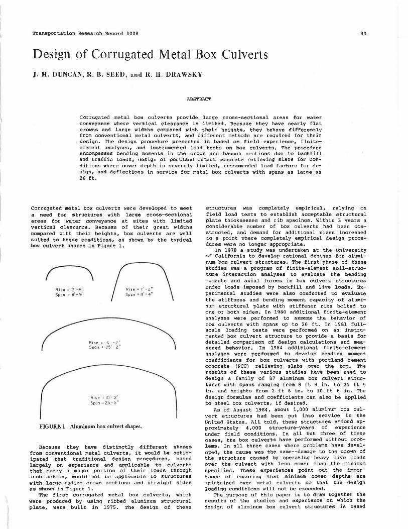
Corrugated metal box culverts were developed to meet a need for structures with large cross-sectional areas for water conveyance at sites with limited vertical clearance. Because of their great widths compared with their heights, box culverts are well suited to these conditions, as shown by the typical box culvert shapes in Figure 1.
Rise= 2 1 -6 11
Span = 8' - 9"
Rise = 6 1 -2 11
Span= 25'-2"
Rise = 10'-2" Span =25'-5"
R' se ..: 7 ' .. 2 " Spon • il' • 4"
FIGURE 1 Aluminum box culvert shapes.
Because they have distinctly different shapes from conventional metal culverts, it would be anticipated that traditional design procedures, based largely on experience and applicable to culverts that carry a major portion of their loads through arch action, would not be applicable to structures with large-radius crown sections and straight sides as shown in Figure 1.
The first corrugated metal box culverts, which were produced by using ribbed aluminum structural plate, were built in 1975. The design of these
structures was completely empirical, relying on field load tests to establish acceptable structural plate thicknesses and rib spacings. Within 3 years a considerable number of box culverts had been constructed, and demand for additional sizes increased to a point where completely empirical design procedures were no longer appropriate.
In 1978 a study was undertaken at the University of California to develop rational designs for aluminum box culvert structures. The first phase of these studies was a program of finite-element soil-structure interaction analyses to evaluate the bending moments and axial forces in box culvert structures under loads imposed by backfill and live loads. Experimental studies were also conducted to evaluate the stiffness and bending moment capacity of aluminum structural plate with stiffener ribs bolted to one or both sides. In 1980 additional finite-element analyses were performed to assess the behavior of box culverts with spans up to 26 ft. In 1981 fullscale loading tests were performed on an instrumented box culvert structure to provide a basis for detailed comparison of design calculations and measured behavior. In 1984 additional finite-element analyses were performed to develop bending moment coefficients for box culverts with portland cement concrete (PCC) relieving slabs over the top. The results of these various studies have been used to design a family of 87 aluminum box culvert structures with spans ranging from 8 ft 9 in. to 25 ft 5 in. and heights from 2 ft 6 in. to 10 ft 6 in. The design formulas and coefficients can also be applied to steel box culverts, if desired.
As of August 1984, about 1,000 aluminum box culvert structures had been put into service in the United States. All told, these structures afford approximately 4 ,000 structure-years of experience under field conditions. In all but three of these cases, the box culverts have performed without problems. In all three cases where problems have developed, the cause was the same--damage to the crown of the structure caused by operating heavy live loads over the culvert with less cover than the minimum specified. These experiences point out the importance of ensuring that minimum cover depths are maintained over metal culverts so that the design loading conditions will not be exceeded.
The purpose of this paper is to draw together the results of the studies and experience on which the design of aluminum box culvert structures is based
34 Transportation Research Record 1008
I I I 1 1 1 1 I I I I 1 1 I 1 1 ! ~-
I I I I ! I I I I I I I I I L .______ I
--- -H--U + ll-- -,_____ 1~ -
[.I -... ' -1<:~
I I ' I I
J I I f777'77'7' ' Beam ElemenlsJ 7 Soil Elements -'
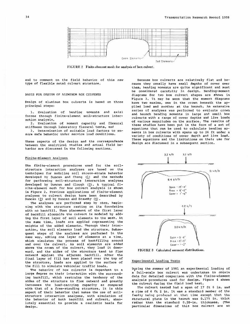
FIGURE 2 Finite-element mesh for analysis of box culvert.
and to comment on the field behavior of this new type of flexible metal culvert structure.
BASIS FOR DESIGN OF ALUMINUM BOX CULVERTS
Design of aluminum box culverts is based on three principal steps:
1. Evaluation of bending moments and axial forces through finite-element soil-structure interaction analysis,
2. Evaluation of moment capacity and flexural stiffness through laboratory flexural tests, and
3. Determination of suitable load factors to ensure safe behavior under service load conditions.
These aspects of the design and the correspondence between the analytical studies and actual field behavior are discussed in the following sections.
Finite-Element Analyses
The finite-element procedures used for the soilstructure interaction analyses are based on the techniques for modeling soil stress-strain behavior developed by Duncan and Chang (1) and the methods for performing soil-structure iii""teraction analyses developed by Duncan and Clough (2). A typical finite-element mesh for box culvert -analysis is shown in Figure 2. Previous applications of finite-element analyses to culvert design have been described by Duncan (_!) and by Duncan and Drawsky (i_) •
The analyses are performed step by step, beginning with the structure resting on its foundation with no backfill. Then placement of the first layer of backfill alongside the culvert is modeled by adding the first layer of soil elements to the mesh. At the same time, loads are applied representing the weights of the added elements. Through their interaction, the soil elements load the structure. Subsequent steps of the analyses are performed in the same way, adding one layer of elements at a time, which simulates the process of backfilling around and over the culvert. As soil elements are added above the crown of the culvert, they load it downward, and the sides of the structure tend to flex outward against the adjacent backfill. After the final layer of fill has been placed over the top of the structure, loads are applied to the surface of the fill to simulate vehicular traffic loads.
The behavior of box culverts is dependent to a large degree on their interaction with the surrounding backfill, which restrains the tendency of the sides of the structure to flex outward and greatly increases the load-carrying capacity as compared with that of a free-standing structure. It is this aspect of their behavior that makes the use of soilstructure interaction analyses, with simulation of the behavior of both backfill and culvert, absolutely essential to provide a realistic basis for design.
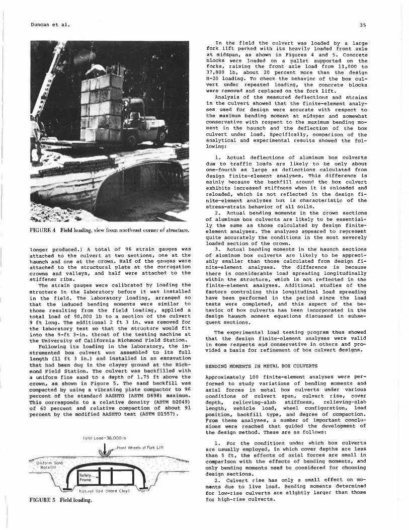
Because box culverts are relatively flat and because they usually have small depths of cover over them, bending moments are quite significant and must be considered carefully in design. Bending-moment diagrams for two box culvert shapes are shown in Figure 3. It may be seen that the moment diagrams have two maxima, one in the crown beneath the applied load and another at the haunch. An extensive series of analyses was performed to evaluate crown and haunch bending moments in large and small box culverts with a range of cover depths and live loads of various magnitudes on the surface. The results of these studies have been put in the form of a set of equations that can be used to calculate bending moments in box culverts with spans up to 26 ft under a variety of conditions of cover depth and live load. These equations and the limitations on their use for design are discussed in a subsequent section.
wyn
3.2 k/ft 3.2 k/ft
! !
8.4 k fl/ft
Span ~ 15' -4"
Rise = 61 -2" Cover = 1' -6 11
4. 2 k/ft
Span~ 9'-5"
Rise = 6'-o" cover = 1
1 - o"
FIGURE 3 Calculated moment distributions.
Experimental Loading Te s t s
})J\l'Yfi
D~ring the summer of 1981 an experimental loading of a full-scale box culvert was undertaken to obtain data for detailed comparison with the finite-element analysis procedures used for design. Figure 4 shows the culvert during the field load test.
The culvert tested had a span of 17 ft 6 in. and a rise of 6 ft 2 in. It was a standard member of the family being produced at that time except that the structural plate in the haunch was 0.175 in. thick rather than the standard 0.20-in. thickness. (The particular dimensions of this box culvert are no
Duncan et al.
FIGURE 4 Field loading, view from northeast corner of structure.
longer produced.) A total of 96 strain gauges was attached to the culvert at two sections, one at the haunch and one at the crown. Half of the gauges were attached to the structura l p lat e at the corrugation crowns and valleys, and half were attached to the stiffener ribs.
The strain gauges were calibrated by loading the structure in the laboratory before it was installed in the field. The laboratory loading, arranged so that the induced bending moments were similar to those resulting from the field loading, applied a total load of 50,000 lb to a section of the culvert 9 ft long. The additional 2 ft 3 in. was removed for the laboratory test so that the structure wou l d fit into the 9-ft 3-in. throat of the testing machine at t he Uni versity o f Californ ia Richmond Field Stat i on.
Follow i ng i t s l oading i n t he labor atory , the ins t r umented box c ulver.t wa s assembled to its .full l ength (11 f t 3 in.) a nd i nstalled i n a.n e xcava t i on t ha t had bee n dug in t he clayey g round a t t he Richmond Fi eld S t a tion. The c ulvert was backfilled wi th a uniform fine sand to a depth of 1.75 ft above the crown, as shown i n F i gu r e 5. The s and backfil l was compacted by using a v i brating pl ate compac tor t o 96 percent o f the standard AASHTO (ASTM 0698) maximum . This correspond s t o a r elative density (ASTM 02049) of 60 perce n t and r elati ve compact i on o f a bou t 9 1 pe rcent by the modif ied AASHTO t e s t (ASTM Dl 557) •
Total Load• 38, 000 lb
~- . . """""" . . Uni t6r~ S0nd
~F:ont Whee~s ::;,;::,Lif: ~ · Backfill
FIGURE 5 Field loading.
35
In the field the culvert was loaded by a large fork lift parked with its heavily loaded front axle at midspan, as shown in Figures 4 and 5. Concrete blocks were loaded on a pallet supported on the forks, raising the front axle load from 11,000 to 37 ,800 lb, about 20 percent more than the design H-20 loading. To check the behavior of the box culvert under repeated loading, the concrete blocks were removed and replaced on the fork lift.
Analysis of the measured deflections and strains in the culvert showed that the finite-element analyses used for design were accurate with respect to the maximum bending moment at midspan and somewhat conservative with respect to the maximum bending moment in the haunch and the deflection of the box culvert under load. Specifically, comparison of the analytical and experimental results showed the following:
1. Actual deflections of aluminum box culverts due to traffic loads are likely to be only about one-fourth as large as deflections calculated from design finite-element analyses. This difference is mainly because the backfill around the box culvert exhibits increased stiffness when it is unloaded and reloaded, which is not reflected in the design finite-element analyses but is characteristic of the stress-strain behavior of all soils.
2. Actual bending moments in the crown sections of aluminum box culverts are likely to be essentially the same as those calculated by design finiteelement analyses. The analyses appeared to represent quite accurately the conditions in the most severely loaded section of the crown.
3. Actual bending moments in the haunch sections of aluminum box culverts are likely to be appreciably smaller than those calculated from design finite-element analyses. The difference is because there is considerable load spreading longitudinally within the structure, which is not reflected in the finite-element analyses. Additional studies of the factors controling this longitudinal load spreading have been performed in the period since the load tests were completed, and this aspect of the behavior of box culverts has been incorporated in the design haunch moment equations discussed in subsequent sections.
The experimental l oad testing program thus showed that the design finite-element a nalyses were valid in some respects and conservative in others and provided a basis for ref i nemen t of box c ulvert designs.
BENDING MOMENTS IN METAL BOX CULVERTS
Approximately 100 finite-element analyses were performed to study variations of bending moments and axial forces in metal box culverts under various conditions of culvert span, culvert rise, cover depth, reliev i ng-sl ab stiffness , relieving-slab leng th , vehicle i oad , wheel configurat i on, l oad posi t i on, backfill type , and degree of compaction. From these ana l yses , a number of importan t conc lus i ons wer e r e ached t hat gu ided t he development of the design method. These are as follows:
1. For the conditions under which box culverts are usually employed , in which cover depths a re l ess than 5 ft , t he effects of axial forces a r e s mall in c omparison wi th t he effects o f bending moments , and only bending momen ts need be considered for choos ing design sections.
2. Culvert rise has only a small effect on moments due to live load. Bending moments determined for low-rise culverts are slightly larger than those for high-rise culverts.
36
3. The effectiveness of relieving slabs in reducing live-load moments increases as the distance that they project beyond the edge of the culvert increases.
4. The critic al position for vehicle loads is always at or near center span.
5, Backfill quality and density have some slight effects on culvert bending moments ; better backfill quality and higher degrees of compaction result in smaller moments. For purposes of design , however, bending moment coefficients have been based on results of analyses that use the lowest quality acceptable backfill, a clay of low plasticity compacted to 90 percent of standard AASHTO maximum dry density (CL90 backfill) •
BENDING MOMENTS DUE TO BACKFILL AND COVER LOADS
Bending moments induced by backfill up to the crown level of box culverts vary quite significantly with the rise/span ratio of the culvert. High-rise culverts bend inward more at the sides and upward more at the crown during early stages of backfilling than do low- r ise culverts. As cover is placed over the crown and as live loads are applied to the backfill over the culvert, the crowns of both high-rise and low-rise culverts bend downward. The critical design condition is always one of downward bending in the crown due to cover and live load, and it has been found to be conservative to neglect the early upward bending in high-rise box culverts and to base designs of both high- and low-rise culverts on the results of analyses of low-rise structures. Such an approximation appears justified in view of the simplicity it affords by eliminating rise as a factor and because the bending moments due to backfilling just up to the crown level are a small part (typically less than 10 percent) of the total design moment, Thus the bending moments discussed in the following paragraphs are those determined for low-rise structures; they are slightly conservative when applied to high-rise structures.
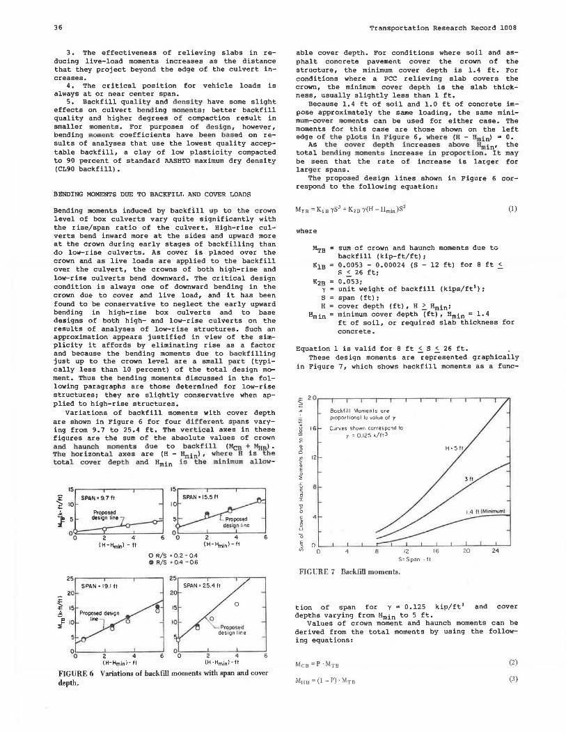
Variations of backfill moments with cover depth are shown in Figure 6 for four di ffe r ent spans varying from 9.7 to 25.4 ft. The verti cal axes in these figures are the sum of the absolute values of crown a nd haunch moments due to back fi ll <Mee + MBal • The hor i zontal axes are (H - Hminl , whe re H is the total cover dep th and Hmin is t he mi nimum allow-
15 15
= SPAN• 9.7 ft SPAN= 15.5 ft
~ 10 10
lo Proposed
1 5 desi9n line Proposed desl9n line
00 2 4· 6 2 4 6 ( H-Hmin> - ft (H-Hminl- fl
0 R/S • 0 .2 - 0 .4 Cl R/ S = 0 4 - 0.6
25 25 SPAN • 19.1 ft SPAN • 25.4 ft
20 20
~ 15 0
~ m
10 ... :::i: Proposed
des ign line
0o 2 4 6 °o 2 4 6 (H-Hminl-ft (H · Hmin>-ft
FIGURE 6 Variations of backfill moments with span and cover depth.
Transportation Research Record 1008
able cover depth. For conditions where soil and asphalt concrete pavement cover the crown of the structure, the minimum cover depth is 1.4 ft. For conditions where a PCC relieving slab covers the crown, the minimum cover depth is the slab thickness, usually slightly less than 1 ft.
Because 1.4 ft of soil and 1.0 ft of concrete impose approximately the same loading, the same minimum-cover moments can be used for either case. The moments for this case are those shown on the left edge o f the plots in Figu r e 6, wher e (H - Hm1nl = O.
As t he cover dept h i ncreases above Hm i n• the total bend ing moments increase i n proportion . It may be s een that the rate of increase is larger for larger spans.
The proposed design lines shown in Figure 6 correspond to the following equation:
where
~B sum of crown and haunch moments due to backfill (kip-ft/ft); 0.0053 - 0.00024 (S - 12 ft) for 8 ft .S. s .s. 26 ft; 0.053; unit weight of backfill (kips/ft'); span (ft); cover depth (ft), H ~ Hmin1
(I )
minimum cover depth (ft), Hmin = 1.4 ft of soil, or required slab thickness for concrete.
Equation 1 is valid for 8 ft .S. S .S. 26 ft. These design moments are represented graphically
in Figure 7, which shows backfill moments as a func-
FIGURE 7 Backfill moments.
tion of span for y = 0.125 kip/ft' and cover depths varying from Hmin to 5 ft.
Values of crown moment and haunch moments can be derived from the total moments by using the following equations:
Mc B=P·Mni (2)
(3)
Duncan et al.
where
Mes crown moment due to backfill (kip-ft/ft), Mila • haunch moment due to backfill (kip-ft/ft),
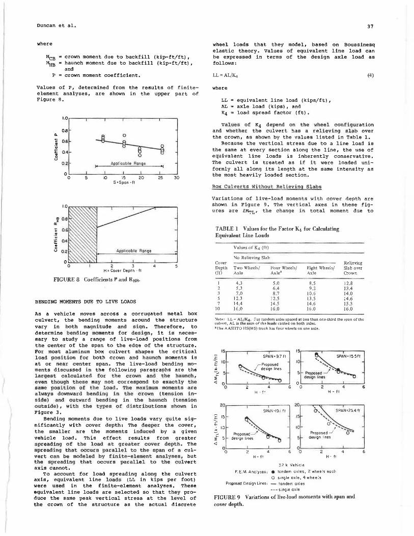
and P s crown moment coefficient.
Values of P, determined from the results of finiteelement analyses, are shown in the upper part of Figure 8.
1.0
o.e 0.
~ c 0 .6 .. ~ 0.4 .. 0 0 u
0 .2
0
~ o.e a:: c .. ·u := o." .. 0
u 0.2
0 s
I• Applicab le Ran2e
10 15 20 S =Span · ft
Appltcable RonQe
3 H• Cover Depth -ft
FIGURE 8 Coefficients P and RHB·
BENDING MOMENTS DUE TO LIVE LOADS
•I
25
4
30
5
As a vehicle moves across a corrugated metal box culvert, the bending moments around the structure vary in both magnitude and sign. Therefore, to determine bending moments for design, it is necessary to study a range of live-load positions from the center of the span to the edge of the structure. For most aluminum box culvert shapes the critical load position for both crown and haunch moments is at or near center span. The live-load bending moments discussed in the following paragraphs are the largest calculated for the crown and the haunch, even though these may not correspond to exactly the same position of the load. The maximum moments are always downward bending in the crown (tension i nside) and outward bending in the haunch (tension outside), with the types of distributions shown in Figure 3.
Bending moments due to live loads vary quite significantly with cover depth: The deeper the cover, the smaller are the moments induced by a given vehicle load. This effect results from greater spreading of the load at greater cover depth. The spreading that occurs parallel to the span of a culvert can be modeled by finite-element analyses, but t.he spreading that occurs parallel to the culvert axis cannot.
To account for load spreading along the culvert axis, equivalent line loads (LL in kips per foot) were used in the finite-element analyses. These equivalent line loads are selected so that they produce the same peak vertical stress at the leve l of the crown of the structure as the actual discrete
37
wheel loads that they model, based on Boussinesq elastic theory. Values of equivalent line load can be expressed in terms of the design axle load as follows:
LL= AL/Ki
where
equivalent line load (kips/ft) , axle load (kips), and load spread factor (ft).
(4)
Values of K4 depend on the wheel configuration and whether the culvert has a reliev ing slab over the crown, as shown by the values listed in Table 1.
Because the vertical stress due to a line load is the same at every section along the line, the use of equivalent line loads is inherently conservative. The culvert is treated as if it were loaded uniformly all along its length at the same intensity as the most heavily loaded section.
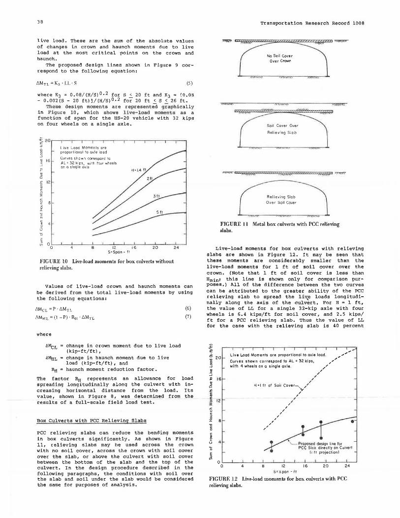
Box Culverts Without Relieving Slabs
Variations of live-load moments with cover depth are shown in Figure 9. The vertical axes in these figures are t:M.rL• the change in total moment due to
TABLE 1 Values for the Factor Ki for Calculating Equivalent Line Loads
Values of K4 (ft)
No Relieving Slab Cover Relieving Depth Two Wheels/ Four Wheels/ Eight Wheels/ Slab over (ft) Axle Axle• Axle Crown
I 4.3 5.0 8.5 12.8 2 5.3 6,4 9.2 I 3.4 3 7.0 8.7 l0 .6 14.0 5 12.3 12.5 13.5 14.6 7 14.4 14.5 14.6 15 .3
10 16.0 16 .0 16.0 16 .0
Note: LL= AL/~ . f.'or tandom axles spaced at less than one-third the span of the culvert 1 AL i i ch~ :sum of the londs carried on bo th axles. a The AASHTO HS(MS) truck has four wheels on one axle.
15~--~---~----.
i 10 .. '"2 5 ::i:
SPAN•9.7 ft 10
s
~ 00...._ _ _ ~2---~--~6 °0...._ _ _ ~2---~4----6
H -ft
20.----..--,----.,~--~
SPAN•19,I ft
~ 15
.;. 10 -:, i" 5 ~ .~~~
O'---~-..__• __ _,,~--~
0 2 4 6 H- ft
15
10
5
32k Vehicle
' o,,
H - ft
', o'•
SPAN=254 fl
; .. · ......... Proposed _/ 5~-
design lines
F. E.M. Analyses, e tandem axles, 2 wheels eoch
O single axle, 4 wheels
Proposed Design Lines, - tandem axles
--- single axle
FIGURE 9 Variations of live-load moments with span and cover depth.
38
live load. These are the sum of the absolute values of changes in crown and haunch moments due to live load at the most er i tical points on the crown and haunch.
The proposed design lines shown in Figure 9 correspond to the following equation:
(5)
where K3 ~ O.OB/ (H/ S)0.2 for S .s_ 20 ft and K3 = [O.OB - 0.002(S - 20 ft)]/(H/S)0.2 for 20 ft < S < 26 ft.
•rhese design moments are rep·r esented g raphically in Figur e 10, which shows l ive-load moments as a function of span for the HS-20 vehicle with 32 kips on four wheels on a single axle.
~20.---r~-.-~..--,c----r~-.--~..--,c---r~-.--~..-~~-.
'f g .9 ~ IG :J E
8 ~ 12 c "' E 0 :<
E
Live Load Moments ore proportional to ox.le load
Curves shown correspcnd to AL' 32 kips with four wheels on a single cixle
~
~ 00:---'-~-4.____..~--;.s~-'-~~12e-.--1~-1~s~-'-~2~0~ ...... ~J2~4---'
S'Spon- ft
FIG URE IO Live-load moments for box culverts without relieving slabs.
Values of live-load crown and haunch moments can be derived from the total live-load moments by using the following equations:
MicL = p ' b.MTL
b.Mtt L= (! -P) ·RH ·b.Mn
where
change in crown moment due to live load (kip-ft/ft), change in haunch moment due to live load (kip-ft/ft), and haunch moment reduction factor.
(6)
(7 )
The factor RH represents an allowance for load spreading longitudinally along the culvert with increasing horizontal distance from the load. Its value, shown in Figure B, was determined from the results of a full-scale field load test.
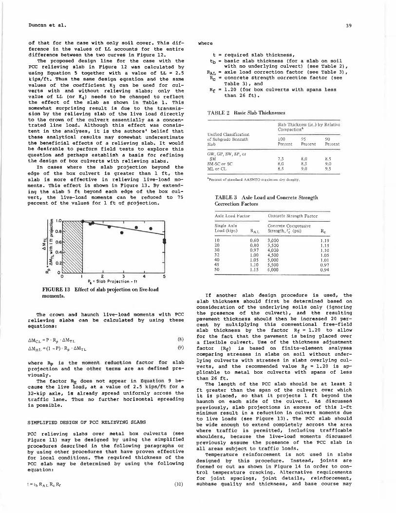
Box Culverts with PCC Relieving Slabs
PCC relieving slabs can reduce the bending moments in box culverts significantly. As shown in Figure 11, relieving slabs may be used across the crown with no soil cover, across tbe crown with soil cover over the slab, or above the culvert with soil cover between the bottom of the slab and the top of the culvert. In the design procedure described in the following paragraphs, the conditions with soil over the slab and soil under the slab would be considered the same for purposes of analysis.
Transportation Research Record 1008
OXWA\
Over CrCWrfn
Soil Cover Over
Relieving Slob
,,,,,_- c " hl!6'iAf I" I? I? f::h.!ffl(
Relieving Slob Over Soil Cover
''' F~ 77;eyrr
FIGURE 11 Metal box culverts with PCC relieving slabs.
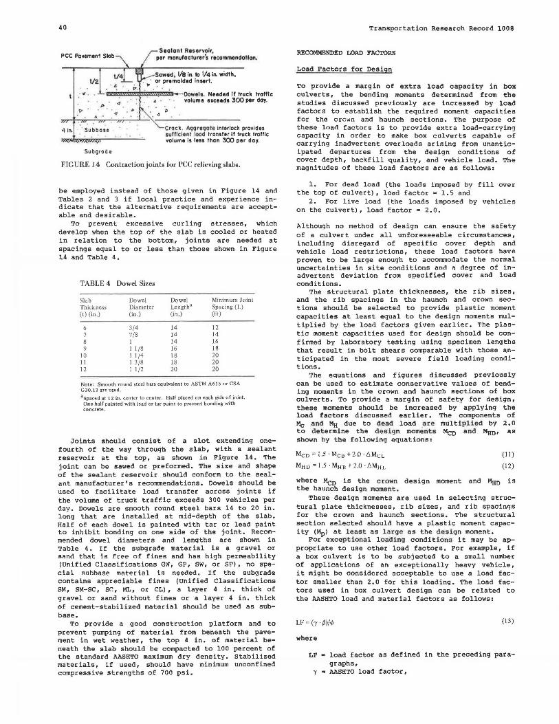
Live-load moments for box culverts with relieving slabs are shown in Figure 12. It may be seen that these moments are considerably smaller than the live-load moments for 1 ft of soil cover over the crown. (Note that 1 ft of soil cover is less than Hminl this line is shown only for comparison purposes.) All of the difference between the two curves can be attributed to the greater ability of the PCC relieving slab to spread the liv,e loads longitudinally along the axis of the culvert. For H = 1 ft, the value of LL for a single 32-kip axle with four wheels is 6.4 kips/ft for soil cover, and 2.5 kips/ ft for a PCC relieving slab. Thus the value of LL for the case with the relieving slab is 40 percent
.., 20
~ ~ ::; R 16
~ Jf! c .. ~ 12 :E
-:; c
" 0 :r 8 .., c 0
E ~
Live Load Moments ore proportional to axle load.
Curves shown correspond to AL• 32 kips, with 4 wheels on a sin9le axle .
4
H •I ft of Soil Cover-,\/"
,, ,,
B
" ,, /
.I
/ .I
12
.I /
.I .I
.I
S• Span · f t
.I
16
.I .I
" " " / /
20
,,"'' "
,,, ... ,,, ...
24
FIGURE 12 Live-load moments for box culverts with PCC relieving slabs.
Duncan et al.
of that for the case with only soil cover. This difference in the values of LL accounts for the entire difference between the two curves in Figure 12.
The proposed design line for the case with the PCC relieving slab in Figure 12 was calculated by using Equation 5 together with a value of LL = 2. 5 kips/ft. Thus the same design equation and the same values of the coefficient KJ can be used for culverts with and without relieving slabs; only the value of LL (or K4) needs to be changed to reflect the effect of the slab as shown in Table 1. This somewhat surprising result is due to the transmission by the relieving slab of the live load directly to the crown of the culvert essentially as a concentrated line load. Although this effect was consistent in the analyses, it is the authors' belief that these analytical results may somewhat underestimate the beneficial effects of a relieving slab. It would be desirable to perform field tests to explore this question and perhaps establish a basis for refining the design of box culverts with relieving slabs.
In cases where the slab projection beyond the edge of the box culvert is greater than l ft, the slab is more effective in relieving live-load moments. This effect is shown in Figure 13. By extending the slab 5 ft beyond each edge of the box culvert, the live-load moments can be reduced to 75 percent of the values for l ft of projection.
P5 =Slob Projection - It
FIGURE 13 Effect of slab projection on live-load moments.
The crown and haunch live-load moments with PCC relieving slabs can be calculated by using these equations:
6McL =P · Rp · 6MTL
6MHL =(! -P) · Rp · 6Mn
(8)
(9)
where Rp is the moment reduct ion factor for slab projection and the othe r terms are as defined previously.
The factor RH doe s not appear in Equa tion 9 because the live load, at a value of 2.5 kips/ft for a 32-kip axle, is already spread uniformly across the traffic lane. Thus no further horizontal spreading is possible,
SIMPLIFIED DESIGN OF PCC RELIEVING SLABS
PCC relieving slabs over metal box culverts (see Figure 11) may be designed by using the simplified procedures described in the following paragraphs or by using other procedures that have proven effective for local conditions. The required thickness of the PCC slab may be determined by using the following equation:
(10)
39
where
t m required slab thickness, tb basic slab thickness (for a slab on so i l
with no underlying culvert) (see Table 2), RAL • axle load correction factor (see Table 3),
Re = concrete strength correction factor (see Table 3), and
Rf 1.20 (for box culverts with spans less than 26 ft),
TABLE 2 Basic Slab Thicknesses
Slab Thickness (in.) by Relative Compaction a
Unified Classification of Subgrade Beneath 100 95 Slab Percent Percent
GW, GP, SW, SP, or SM 7,5 8,0
SM-SC or SC 8.0 8.5 ML or CL 8.5 9.0
3 Percent of standard AASHTO maximum dry density.
TABLE 3 Axle Load and Concrete Strength Correction Factors
Axle Load Factor
Single Axle Load (kips)
IO 20 30 32 40 45 50
0.60 0.80 0.97 I.OD 1.05 I.ID 1.15
Concrete Strength Factor
Concrete Compressive Strength, f~ (psi)
3,000 3,500 4,000 4,500 5,000 5,500 6,000
90 Percent
8.5 9.0 9.5
1.19 1.15 1.10 1.05 I.OJ 0.97 0.94
If another slab design procedure is used, the slab thickness should first be determined based on consideration of the underlying soils only (ignoring the presence of the culvert) , and the resulting pavement thickness should then be increased 20 percent by multiplying this conventional free-field slab thickness by the factor Rf = l,20 to allow for the fact that the pavement is being placed over a flexible culvert. Use of the thickness adjustment factor (Rf) is based on finite-element analyses comparing stresses in slabs on soil without underlying culverts with stresses in slabs overlying culverts, and the reconunended value Rf = 1. 20 is applicable to metal box culverts with spans of less than 26 ft,
The length of the PCC slab should be at least 2 ft greater than the span of the culvert over which it is placed, so that it projects l ft beyond the haunch on each side of the culvert. As discussed previously, slab projections in excess of this 1-ft minimum result in a reduction in culvert moments due to live loads (see F i gure 13). The PCC slab should be wide enough to extend completely across the area where traffic is permitted, including trafficable shoulders, because the live-load moments discussed previously assume the presence of the PCC slab in all areas subject to traffic loads.
Temperature reinforcement is not used in slabs designed by this procedure. Instead, joints are formed or cut as shown in Figure 14 in order to control temperature cracking. Alternative requirements for joint spacings, joint details, reinforcement, subbase quality and thickness, and base course may
40
4 in.
1/2
Sealant Reservoir, per monulaclurers racommendollon.
Sawed, 1/8 in. to l/4 in. width, or premolded insert.
· <f . l'ZZIZZ!Z!l7Zli!l1Zi$Z~2Z?Zlllllll>-o- Oowel 1. Needed if !ruck traffic
I>
Sub9rade
volume exceeds 300 per day.
Crock. Aqqre9ate interlock provides sullicionl toad transfer ii truck trallic volume is less !hon 300 per day.
FIG URE 14 Contraction joints for PCC relieving slabs.
be employed instead of those given in Figure 14 and Tables 2 and 3 if local practice and experience indicate that the alternative requirements are acceptable and desirable.
To prevent excessive curling stresses, which develop when the top of the slab is cooled or heated in relation to the bottom, joints are needed at spacings equal to or less than those shown in Figure 14 and Table 4.
TABLE 4 Dowel Sizes
Slab Dowel Dowel Minimum Joint Thickness Dia meter Length3 Spacing (L) (t) (in.) (in.) (in.} (ft)
6 3/4 14 12 7 7/8 14 14 8 1 14 16 9 1 1/8 16 18
JO l l /4 18 20 11 1 3/8 18 20 12 1 I /2 20 20
Note: Smooth round steeJ bars equiva]ent to ASTM A61S or CSA GJ0.12 are used. 8Spaced at 12 in. center to center. Half placed o n each side of joint.
One-half painted with lead or tar paint to prevent bonding with concrete.
Joints should consist of a slot extending onefourth of the way through the slab, with a sealant reservoir at the top, as shown in Figure 14. The joint can be sawed or preformed. The size and shape of the sealant reservoir should conform to the sealant manufacturer's recommendations. Dowels should be used to facilitate load transfer across joints if the volume of truck traffic exceeds 300 vehicles per day. Dowels are smooth round steel bars 14 to 20 in. long that are installed at mid-depth of the slab. Half of each dowel is painted with tar or lead paint to inhibit bonding on one side of the joint. Recommended dowel diameters and lengths are shown in Table 4. If the subgrade material is a gravel or sand that is free of fines and has high permeability (Unified Classifications GW, GP, SW, or SP), no special 1rnhh<1se materiiil is needed. If the subgrade contains appreciable fines (Unified Classifications SM, SM-SC, SC, ML, or CL), a layer 4 in. thick of gravel or sand without fines or a layer 4 in. thick of cement-stabilized material should be used as subbase,
To provide a good construction platform and to prevent pumping of material from beneath the pavement in wet weather, the top 4 in. of material beneath the slab should be compacted to 100 percent of the standard AASHTO maximum dry density. Stabilized materials, if used, should have minimum unconfined compressive strengths of 700 psi.
Transportation Research Record 1008
RECOMMENDED LOAD FACTORS
Load Factors for Design
To provide a margin of extra load capacity in box culverts, the bending moments determined from the studies discussed previously are increased by load factors to establish the required moment capacities for the crown and haunch sections. The purpose of these load factors is to provide extra load-carrying capacity in order to make box culverts capable of carrying inadvertent overloads arising from unanticipated departures from the design conditions of cover depth, backfill quality, and vehicle load. The magnitudes of these load factors are as follows:
1. For dead load (the loads imposed by fill over the top of culvert), load factor = 1.5 and
2. For live load (the loads imposed by vehicles on the culvert), load factor s 2.0.
Although no method of design can ensure the safety of a culvert under all unforeseeable circumstances, including disregard of specific cover depth and vehicle load restrictions, these load factors have proven to be large enough to accommodate the normal uncertainties in site conditions and a degree of inadvertent deviation from specified cover and load conditions.
The structural plate thicknesses, the rib sizes, and the rib spacings in the haunch and crown sect ions should be selected to provide plastic moment capacities at least equal to the design moments multiplied by the load factors given earlier. The plastic moment capacities used for design should be con£ irmed by laboratory testing using specimen lengths that result in bolt shears comparable with those anticipated in the most severe field loading conditions.
The equations and figures discussed previously can be used to estimate conservative values of bending moments in the crown and haunch sections of box culverts. To provide a margin of safety for design, these moments should be increased by applying the load factors discussed earlier. The components of Mc and MH due to dead load .are multip l i ed by 2.0 to determine the design moment s Meo and MHD• as shown by the following equations:
Me o : 1.5 ·Mee + 2.0 · 6 Mc L
MH o : J5· MH e + 2D·6MH L
(11)
(12)
where Meo is the crown design moment and MHo is the haunch design moment.
These design moments are used in selecting structural plate thicknesses, rib sizes, and rib spacings for the crown and haunch sections. The structural section selected should have a plastic moment capacity (Mpl at l e as t as large as the design moment.
For exceptional loading condit i ons it may be appropriate to use other load factors. For example, if a box culvert is to be subjected to a small number of applications of an exceptionally heavy vehicle, it might be considered acceptable to use a load factor smaller than 2.0 for this loading. The load factors used in box culvert design can be related to the AASHTO load and material factors as follows:
LF: c-r ·rm~ (13)
where
LF load factor as defined in the preceding paragraphs,
y AASHTO load factor,
Duncan et al.
S AASHTO load coefficient, and ~ AASHTO capacity modification factor.
The values of LF = 2.0 for live load and LF = 1.5 for dead load correspond to values of SL = 1. 67, SE = 1.25, y = 1.20, and ~ = 1.00 in the AASHTO system. These are compared with the values specified by AASHTO for various types of structures in Table 5. ·
TABLE 5 Comparison of AASHTO and Recommended Design Factors
Factor
Live-load coefficient (IJL) Dead-load coefficient (f3d Load factor (')') Capacity modification factor(¢) Impact factor (I)(%)
AASHTO
1.0-2.2 1.0-1.5 L0-1.3 0.67 0-30
Recommended
1.67 1.25 1.20 LOO 0
The values of the coefficients that are used in the recommended design procedures have been selected considering that aluminum box culverts receive considerable engineering attention and are more carefully constructed than small conventional metal culverts. The value of ~ = 1. 00 was selected considering that the aluminum structural properties are minimum property values rather than typical values as used in connection with AASHTO designs. The impact factor of 0 percent is believed justified by the strong influence of soil-structure interaction in box culverts: Under rapid loadings well-compacted soils react with increased stiffnes s and a great deal of inertia, resulting in greater rather than smaller margins of safety under loads that are applied for brief periods of time.
The experience with box culverts to date and the complete absence of problems attributable to design deficiencies provide considerable support for continued use of the recommended factors for box culverts.
DEFLECTIONS IN SERVICE
Deflections of aluminum box culverts, like deflections of other flexible metal culverts, are dependent on many factors, including the type of backfill, backfill compaction, water content of backfill, type of pavement, vehicle weight, and number of load repetitions. Information on deflections of box culverts comes from three sources--finiteelement soil-structure interaction analyses, field loading experiments and measurements, and observations of box culverts in service. These studies and observations indicate the following:
1. The better the quality of the backfill, the more densely it is compacted; and the lower its water content, the smaller are culvert deflections during placement of fill over the crown and during vehicle loading.
2. Stiff pavements, mostly notably PCC pavement slabs, reduce deflections as compared with thin flexible pavements or no pavement over the top of the culvert.
3. Live-load deflections increase in proportion to the vehicle axle load.
4. Deflections are larger under the first application of a particular live load than under subsequent applications of the same load. After many load applications deflections are likely to be about onefourth as large as under the first application of the same load.
41
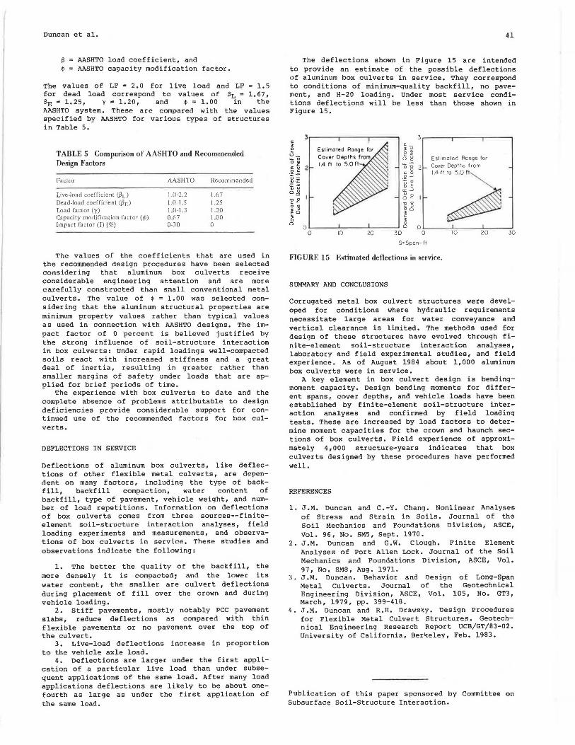
The deflections shown in Figure 15 are intended to provide an estimate of the possible deflections of aluminum box culverts in service. They correspond to conditions of minimum-quality backfill, no pavement, and H-20 loading. Under most service conditions deflections will be less than those shown in Figure 15.
3 3 c
c_ • 0 J "' Li_ 0 "' -"" Range for - "' u 21 Eslimaled 0"'
a~ "" 2 2 _ Cover Depths f rem -c u 0 0 c c 0
'"'~ ·=-=- .9 _J u= Q)i.::: u "' "'"' Q) .~ "' u ;;:: -' o~ "'0 1.-~fl
o- -'C "'
0 "' - ; . ; 00 cO • • c 0 • 0 0
I I 0 0 0 0 10 20 30 0 10 20 30
s~ Span- ft
FIGURE 15 Estimated deflections in service.
SUMMARY AND CONCLUSIONS
Corrugated metal box culvert structures were developed for conditions where hydr aulic requiremP.nts necessitate large areas for water conveyance and vertical clearance is limited. The methods used for design of these structures have evolved through finite-element soil- structure interaction analyses, laboratory and field experimental studies, and field experience. As of August 1984 about 1, 000 aluminum box culverts were in service.
A key element in box culvert design is bendingmoment capacity. Design bending moments for different spans, cover depths, and vehicle loads have been established by finite-element soil-structure interaction analyses and confirmed by field loading tests. These are increased by load factors to determine moment capacities for the crown and haunch sections of box culverts. Field experience of approximately 4,000 structure-years indicates that box culverts designed by these procedures have performed well.
REFERENCES
1. J.M. Duncan and C. -Y. Chang. Nonlinear Analyses of Stress and Strain in Soils. Journal of the Soil Mechanics and Foundations Division, ASCE, Vol. 96, No. SM5, Sept. 1970.
2. J.M. Duncan and G.W. Clough. Finite Element Analyses of Port Allen Lock. Journal of the Soil Mechanics and Foundations Division, ASCE, Vol. 97, No. SM8, Aug. 1971.
3. J.M. Duncan. Behavior and Design Metal Culverts. Journal of the Engineering Division, ASCE, Vol. March, 1979, pp. 399-418.
of Long-Span Geotechnical
105, No. GT3,
4. J.M. Duncan and R.H. Drawsky . Design Procedures for Flexible Metal Culvert Structures. Geotechnical Engineering Research Report UCB/GT/83-02. University of California, Berkeley, Feb. 1983.
Publication of this paper sponsored by Committee on Subsurface Soil-Structure Interaction.