Design of Copper Hydrometallurgy Plants for High … · Design of Copper Hydrometallurgy Plants for...
47
Design of Copper Hydrometallurgy Plants for High Grade Ores and Copper Concentrates David Dreisinger University of British Columbia Vancouver, Canada
Transcript of Design of Copper Hydrometallurgy Plants for High … · Design of Copper Hydrometallurgy Plants for...

Design of Copper Hydrometallurgy Plants for High
Grade Ores and Copper Concentrates
David Dreisinger
University of British Columbia
Vancouver, Canada

Outline
• Leaching of High Grade Ores and Concentrates
• Design Factors
– Copper Extraction
– S/L Separation and Washing
– Acid Balance
– Copper SX-EW
– Precious Metal Recovery
• Other Factors
• GALVANOX – New Technology for Copper Leaching
• Concluding Remarks
2

Simplified Flowsheet
3
Reagents
Wash Final
Water Residue
Raffinate
Bleed
Copper Cathode
Gold and Silver
Copper Leaching
S/L Separation
Copper SX-EW
Precious Metal
Recovery
Copper Ore or Concentrate

Leaching of High Grade Ores and Concentrates
• Developments are primarily related to leaching of high grade chalcocite – pyrite ores and leaching of chalcopyrite concentrates
• Leaching of chalcopyrite is complicated by “passivation” of chalcopyrite under mild conditions
• Most chalcopyrite leaching technologies try to overcome this passivation by one or more techniques
• This is the critical feature of the overall process – without high copper extraction, the process will not be feasible
4

Cu-Fe-S-H2O Diagram

Strategies for Avoiding Passivation
• Leach at potential/pH that avoids passivation (Galvanic Processing).
• Add silver to avoid copper polysulfide (too expensive)
• Fine grind to P80 of less than 10 μm (mineral leaches before passivation)
• Use high temperature (+200 C) or aggressive conditions (transpassive)
• Use chloride or chloride addition
• Use bacteria (thermophiles) that avoid passivation
• Add oxidation catalyst like nitrate or nitrite (NSC)

Sulfur Chemistry
• Sulfur is formed from sulfide minerals during leaching
• Three temperature regimes
• Low T: < 119.3 C – SOLID (S8)
• Medium T: 119.3 C to 159 C – LIQUID (S8)
• High T: +159 C – LIQUID/POLYMER (Sn) – S Oxidized

Low Temperature Leaching (< 119 C)
• Elemental sulfur forms porous product layer
• Kinetics can be slow due to diffusion through sulfur product
Medium Temperature Leaching (119-159 C)
• Molten sulfur is dispersed by addition of a sulfur dispersant/surface active agent
• Lignin sulfonate and Quebracho are two common agents.
• Sulfide mineral becomes sulfophobic and hydrophilic and sulfur liquid droplets are dispersed
High Temperature Leaching (+200 C)
• Transpassive leaching – sulfur fully oxidized to sulfate

Iron Precipitation
• Dissolved iron will be oxidized and precipitated as ferric hydroxide (undesirable), jarosite, goethite or hematite
• Goethite forms at less than °140 C with hematite forming above 140 °C
• Jarosite can form over wide temperature range
• Basic ferric sulfate processes (Sepon) precipitate iron at high free acid and high T (220 °C). Iron forms basic ferric sulfates which then re-dissolve at atmospheric T+P.

Sulfate Processes
Process Status Temp. Press. Ultrafine Chloride Surfactant Special
(°C) (atm) Grind Activox Process D 110 12 Yes No No Albion Process P 85 1 Yes No No AAC- UBC P/C 150 12 Yes No Yes Bactech/Mintek Low T Bioleach
P 35 1 Yes No No
BIOCOP™ C 80 1 No No No Thermo-philes
CESL Process C 150 12 No Yes Yes Cobre Las Cruces C 90 1 No No No Chalcocite
Dynatec P 150 12 No No Yes Coal+
Recycle
Galvanox P 80 1 No No No Galvanic
Mt. Gordon C 90 8 No No No Chalcocite
PLATSOL P 225 32 No Yes No
Sepon Copper C 80 – Cu 1 No No No Chalcocite
220 – FeS2 32 No No No Total Press. Ox. C 225 32 No No No
10

Recent Developments
• Mt. Gordon, Australia – 50,000 tpa Cu X (closed in 2003)
• PD/Freeport Bagdad USA – 16,000 tpa Cu √ (now MoS2)
• Alliance Copper, Chile – 20,000 tpa Cu X (2 year demo plant)
• Sepon Copper, Laos – 90,000 tpa Cu √
• Kansanshi, Zambia - +50,000 tpa Cu √
• PD/Freeport Morenci USA – 75,000 tpa Cu X (long story)
• Cobre Las Cruces, Spain – 72,000 tpa Cu √
• CESL Process, Vale Brazil - 10,000 tpa Cu X (short term demo plant)

Mount Gordon Autoclaves (2X120m3 Capacity)

Cobre Las Cruces 8 X 350 m3 OKTOP Reactors
13
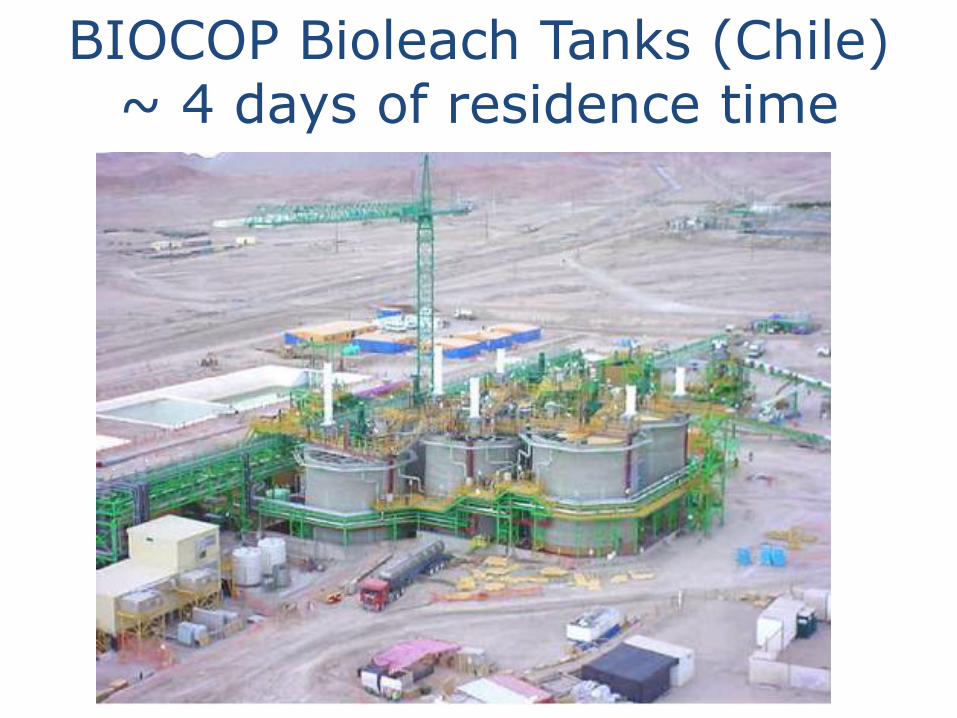
BIOCOP Bioleach Tanks (Chile) ~ 4 days of residence time
14
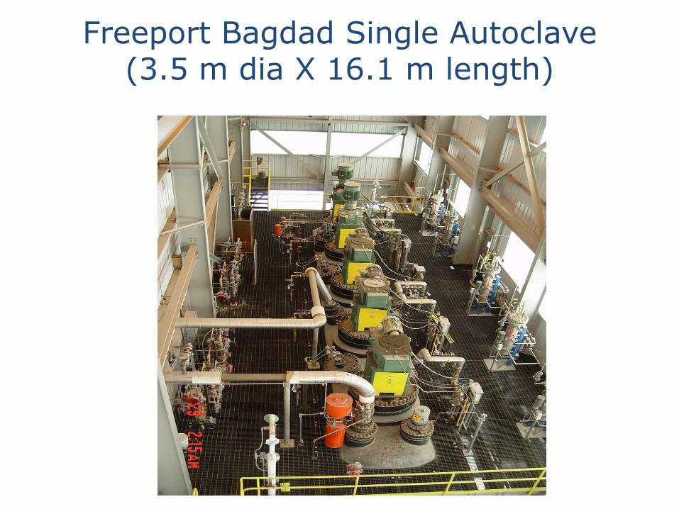
Freeport Bagdad Single Autoclave (3.5 m dia X 16.1 m length)

Solid-Liquid Separation
• The washing of leach residues may be done with;
– Countercurrent decantation (6-7 stages)
– Vacuum belt filter (with 2-3 stages of washing)
– Pressure filter (with washing)
• Wash solutions may include;
– Water
– Raffinate (to close water balance)
• Washing may be intended to recovery
– Copper
– Iron/Acid
• Process selection based on testwork and economic tradeoff
16

Gold Operation
Copper Operation Padan
Camp
Khanong Copper Orebody
Sepon Copper (Clarifier, 4 Raff CCD’s, 3 Water CCD’s)

Mount Gordon Residue Filter – 158 m2 for ~750,000 tpa ore treatment rate
18

Bagdad Concentrate Leach Flowsheet
PLS Pond and SX/EW
Slurry Storage
Tank
Concentrate Slurry PLV
Feed Tank
PLV
CCD #1
Flash Vessel
Strong PLS Tank
Neut #1
Neut #2
Neut #3
Neut #4
Tails
CCD #2 CCD #3 CCD #4
#1
S C R U B B E R
#2
S C R U B B E R
PLS to SX/EW and Cathode Production

Acid Balance (and Oxygen Consumption)
• Acid generation must be balanced with acid consumption
• Partial versus total oxidation
– CuFeS2 + 4.25O2 + H2O = CuSO4 + 0.5Fe2O3 + H2SO4
– CuFeS2 + O2 + 2H2SO4 = CuSO4 + FeSO4 + 2H2O
• Full Oxidation
– 2.15 t of oxygen/t Cu – 3.09 t of acid/t Cu (same as smelting)
• Partial Oxidation
– 0.5 t of oxygen/t Cu – NO Net Acid Production
• Acid may be used for associated heap/dump leach
• If no or little acid consumption, minimize sulfur oxidation
20

Acid Balance (and Oxygen Consumption)
• Acid can also be generated by pyrite
• FeS2 + 3.75O2 + 2H2O = Fe2O3 + 2H2SO4
• Mount Gordon and Cobre Las Cruces – Modest Pyrite Oxidation to make up acid (and iron)
• Mount Gordon – target was 2-3 % Pyrite Oxidation
• Cobre Las Cruces – target is 3-5% Pyrite Oxidation
• Sepon – pyrite and sulfur are floated from the atmospheric leach tailing to make high “S” feed to the high temperature autoclave
21

Freeport Bagdad Flowsheet (140 t/d H2SO4 to Heap (Stockpile) Leach (Marsden, 2003)

23

NEUTRALISATION
WASH CCD
WASH CCD WASH
WATER
TAILINGS Fe Acid
Cu LOSS
Sepon Flowsheet CRUSHING
MILLING
SURGE
CLARIFICATION
SURGE
ATM LEACH
HEX
DIRECT HEX
SX EW
COOLING TWR
RAF CCD
CATHODE
FLOTATION
SURGE
AUTOCLAVE
FILTER
EXCESS
PYRITE
POX LEACH
STEAM
Fe Acid
ADDN
WASH
WATER
9 t/h of Pyrite/Sulfur to total pressure oxidation

Copper SX-EW
• Transfer of copper from strong leach solutions to Cu EW
• Solvent extraction with oximes preferred
• Freeport pioneered direct EW
• Sepon – control of copper concentration in PLS to produce low Cu in raffinate for wash
25

Precious Metal Recovery
• Au may be recovered by cyanidation of copper leach residues.
• However if S present then form SCN and increase the cost of Au recovery.
• Ag often forms Ag-jarosite under copper leaching conditions. May have to use lime boil to decompose Ag-jarosite prior to cyanidation.
• Alternative strategy to use other reagents (eg. S2O3
2-, SCN- or Cl-/Br-)
• PGM Recoveries difficult from residues but possible directly (PLATSOL™)

Other Factors in Design
• Arsenic and minor elements – co-precipitation with iron
• Gypsum scaling – when cooling, try to do so in the presence of solids as “seed”
• Sepon – Cooling tower treats pulp
• Cobre Las Cruces – Cooling tower sees thickener O/F solution
• Materials of construction – high temperatures and pressures (if used) are deleterious for many materials in the presence of acid-copper-iron sulfate solution
• Especially difficult in autoclaves (lots of experience from gold and base metal autoclaves)
27

NEUTRALISATION
WASH CCD
WASH CCD WASH
WATER
TAILINGS Fe Acid
Cu LOSS
Sepon Flowsheet CRUSHING
MILLING
SURGE
CLARIFICATION
SURGE
ATM LEACH
HEX
DIRECT HEX
SX EW
COOLING TWR
RAF CCD
CATHODE
FLOTATION
SURGE
AUTOCLAVE
FILTER
EXCESS
PYRITE
POX LEACH
STEAM
Fe Acid
ADDN
WASH
WATER
9 t/h of Pyrite/Sulfur to total pressure oxidation

29

GALVANOX™ PROCESS
• Process developed by David Dixon with Alain Tshilombo and Ghazaleh Nazari
• Atmospheric leaching of chalcopyrite
30
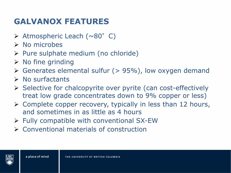
GALVANOX FEATURES
Atmospheric Leach (~80°C)
No microbes
Pure sulphate medium (no chloride)
No fine grinding
Generates elemental sulfur (> 95%), low oxygen demand
No surfactants
Selective for chalcopyrite over pyrite (can cost-effectively treat low grade concentrates down to 9% copper or less)
Complete copper recovery, typically in less than 12 hours, and sometimes in as little as 4 hours
Fully compatible with conventional SX-EW
Conventional materials of construction

GALVANOX CHEMISTRY
GALVANOX takes advantage of the galvanic effect between chalcopyrite and pyrite.
Chalcopyrite is a semiconductor, and therefore corrodes electrochemically in oxidizing solutions.
In ferric sulphate media, the overall leaching reaction is as follows:
CuFeS2 + 2 Fe2(SO4)3 → CuSO4 + 5 FeSO4 + 2 S0
This reaction may be represented as a combination of anodic and cathodic half-cell reactions:
Anodic: CuFeS2 → Cu2+ + Fe2+ + 2 S0 + 4 e–
Cathodic: 4 Fe3+ + 4 e– → 4 Fe2+

Cu2+
Fe2+
4 Fe3+
4 Fe2+
So
4 e-
CuFeS2
Anodic Site Cathodic Site
UNASSISTED CHALCOPYRITE LEACHING

UNASSISTED CHALCOPYRITE LEACHING
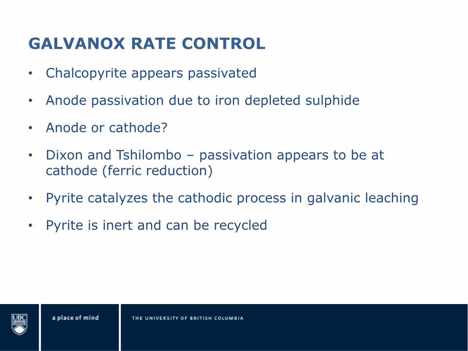
GALVANOX RATE CONTROL
• Chalcopyrite appears passivated
• Anode passivation due to iron depleted sulphide
• Anode or cathode?
• Dixon and Tshilombo – passivation appears to be at cathode (ferric reduction)
• Pyrite catalyzes the cathodic process in galvanic leaching
• Pyrite is inert and can be recycled

Cu2+
Fe2+
So
Py
Py
Cp
4 e- 4 e-
4 Fe3+
4 Fe2+
Anodic Site Cathodic Site
GALVANICALLY ASSISTED CHALCOPYRITE LEACHING

Partially leached particle Completely leached particles
GALVANICALLY ASSISTED CHALCOPYRITE LEACHING

GALVANOX CHEMISTRY
The ferric required for GALVANOX leaching is regenerated in situ with oxygen gas
Ferric leaching of chalcopyrite:
CuFeS2 + 2 Fe2(SO4)3 → CuSO4 + 5 FeSO4 + 2 S0
Oxidation of ferrous with dissolved oxygen gas:
4 FeSO4 + O2 + 2 H2SO4 → 2 Fe2(SO4)3 + 2 H2O
Overall leaching reaction:
CuFeS2 + O2 + 2 H2SO4 → CuSO4 + FeSO4 + 2 S0 + 2 H2O
Conventional SX-EW of Cu and Fe Precipitation

GALVANOX CHEMISTRY
In summary, the overall GALVANOX process chemistry is as follows:
Galvanically-assisted atmospheric leaching of chalcopyrite:
CuFeS2 + O2 + 2 H2SO4 → CuSO4 + FeSO4 + 2 S0 + 2 H2O
Iron oxyhydrolysis:
FeSO4 + ¼ O2 + H2O → ½ Fe2O3 (s) + H2SO4
Copper electrowinning:
CuSO4 + H2O → Cu0 + ½ O2 ↑ + H2SO4
Overall process chemistry:
CuFeS2 + 5/4 O2 → Cu0 + 2 S0 + ½ O2 ↑ + ½ Fe2O3 (s)

BATCH TESTING
Six 3-L jacketed reactors
Water baths for
temperature control
Digital oxygen mass flow
meters for potential
control
Automated data
acquisition for potential,
pH and temperature

0%
10%
20%
30%
40%
50%
60%
70%
80%
90%
100%
0 4 8 12 16 20 24
Time (h)
Cu
Re
co
ve
ry
Py = 150 g (K5)
Py = 100 g (K9)
Py = 50 g (K6)
Py = 25 g (K10)
Py = 0 g (K1)
CHALCOPYRITE CONCENTRATE #1 – 35% Cu Effect of pyrite addition (50 g con, 65 g acid, 470 mV, 80 C)

0%
10%
20%
30%
40%
50%
60%
70%
80%
90%
100%
0 4 8 12 16 20 24
Time (h)
Cu
Re
co
ve
ry
Galvanox Leaching
No Pyrite
CHALCOPYRITE CONCENTRATE #2 – 23.6 % Cu Effect of pyrite addn (30 g con, 120 g Py, 30 g acid, 480 mV, 80 C)

0%
10%
20%
30%
40%
50%
60%
70%
80%
90%
100%
0 4 8 12 16 20 24
Time (h)
Cu
Re
co
ve
ry
Galvanox Leaching
No Pyrite
CHALCOPYRITE CONCENTRATE #3 – 24.1 % Cu Effect of pyrite addn (10 g con, 40 g Py, 15 g acid, 470 mV, 80 C)

0%
10%
20%
30%
40%
50%
60%
70%
80%
90%
100%
0 4 8 12 16 20 24
Time (h)
Cu
Re
co
ve
ry
Galvanox Leaching
No Pyrite
CHALCOPYRITE CONCENTRATE #4 – 20.1 % Cu Effect of pyrite addn (57 g con, 112 g Py, 60 g acid, 450 mV, 80 C)

0%
10%
20%
30%
40%
50%
60%
70%
80%
90%
100%
0 4 8 12 16 20 24
Time (h)
Cu
Re
co
ve
ry
CHALCOPYRITE BULK CONCENTRATE – 10.2% Cu (150 g bulk con @ ~1.21 Py/Cp ratio, 75 g acid, 440 mV, 80 C)

Conclusions
• Hydromet has advanced by;
• Necessity
– Mount Gordon
– Sepon
– Cobre Las Cruces
• Opportunity
– Bagdad
– Kansanshi
• New Process Developments
– Galvanox
• Future is bright for hydromet
46

Thank You!
Any Questions?