Design of Combined Bending and Compression Members in Steel.
17
Design of Combined Bending and Compression Members in Steel
-
Upload
heather-lawson -
Category
Documents
-
view
258 -
download
10
Transcript of Design of Combined Bending and Compression Members in Steel.
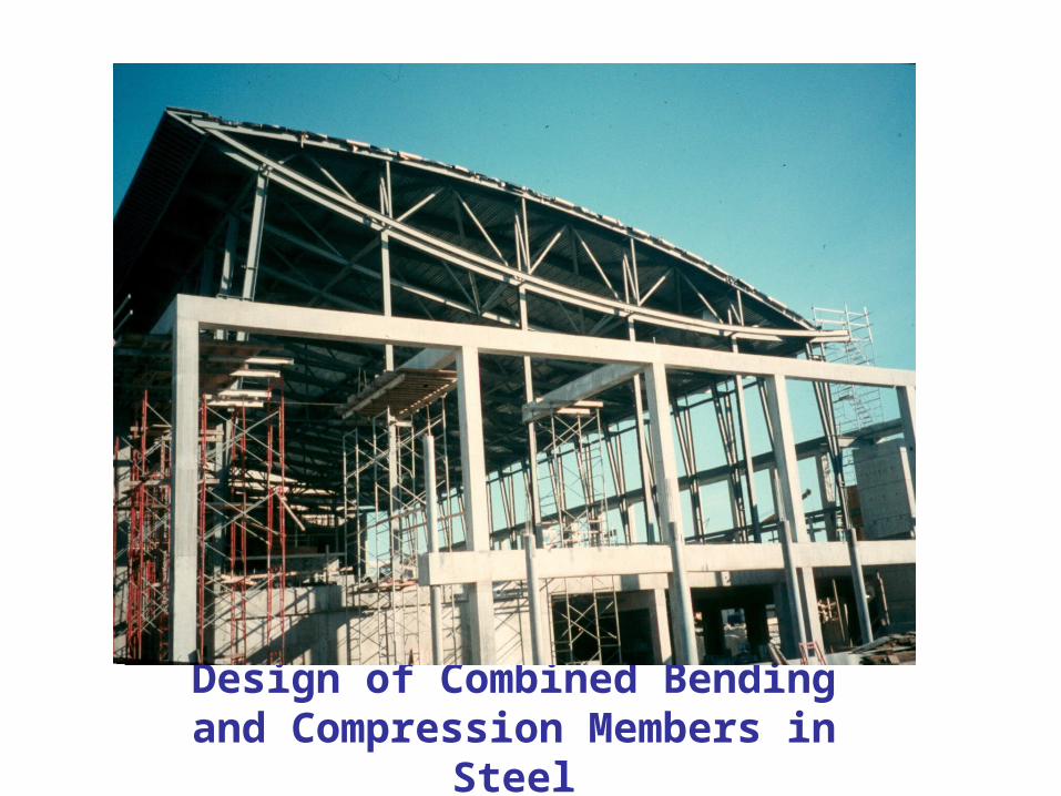
Design of Combined Bending and Compression Members in Steel

Combined stresses
Bi-axial bending
Bending and compression

Multi-story steel rigid frame

• Rigid frames, utilizing moment connections, are well suited for specific types of buildings where diagonal bracing is not feasible or does not fit the architectural design
• Rigid frames generally cost more than braced frames (AISC 2002)

Vierendeel steel truss cycle bridge Beaufort Reach, Swansea

Typical crane columns

neutral axis
fmax = fa + fbx + fby < fdes
( Pf / A ) + ( Mfx / Sx ) + ( Mfy / Sy ) < fdes
(Pf / Afdes) + (Mfx / Sxfdes) + (Mfy / Syfdes) < 1.0
(Pf / Pr) + (Mfx / Mr) + ( Mfy / Mr) < 1.0
x
x
fbx = Mfx / Sx
Mfx
y
yfby = Mfy / Sy Mfy
fa = Pf / A
Pf

Cross-sectional strengthPf/Pr
Mf/Mr
1.0
1.0
Class 1 steel sections
(Pf / Pr) + 0.85(Mfx / Mr) + 0.6( Mfy / Mr) < 1.0
other steel sections
(Pf / Pr) + (Mfx / Mr) + ( Mfy / Mr) < 1.0

Slender beam-columns
• What if column buckling can occur ?
• What if lateral-torsional buckling under bending can occur ?
Use the appropriate axial resistance and moment resistance values in the interaction equation
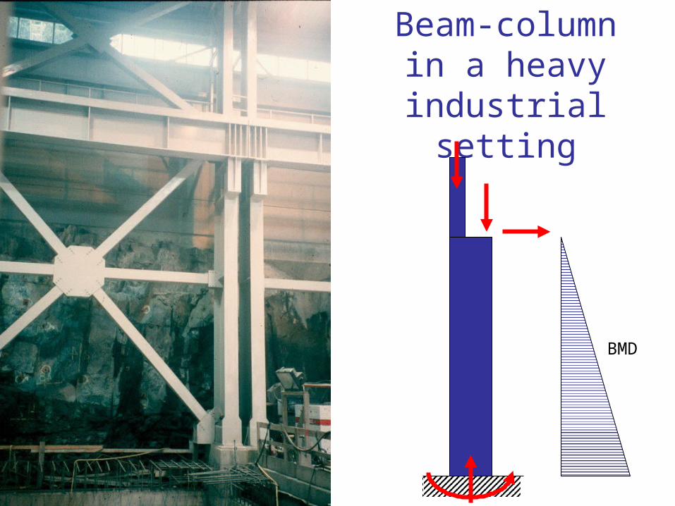
Beam-column in a heavy
industrial setting
BMD

Moment amplification
δ o δmax
P
P
0max
0max
1
1
1
1
MPP
M
PP
E
E
PE = Euler load

Interaction equation
0.111
11
ry
fy
Ey
y
rx
fx
Ex
x
r
f
M
M
PPM
M
PPP
P
Axial load
Bending about y-axis
Bending about x-axis
ω1 = moment gradient factor (see next slide)

Moment gradient factor for steel columns with
end moments
M1
M2
ω1 = 0.6 – 0.4(M1/M2) ≥ 0.4
i.e. when moments are equal and cause a single curvature, then ω1 = 1.0
and when they are equal and cause an s-shape, then ω1 = 0.4

Steel frame to resist earthquake forces
Warehouse building, Los Angeles

Moment gradient factor for other cases
ω1 = 1.0 ω1 = 0.85ω1 = 1.0 ω1 = 0.6 ω1 = 0.4
v

Design of steel beam-columns
1. Laterally supported• Cross-sectional strength
2. Supported in the y-direction• Overall member strength• Use moment amplification factor• Use buckling strength about x-axis (Crx)
3. Laterally unsupported• Buckling about y-axis (Cry)• Lateral torsional buckling (Mrx)• Use moment amplification factors• Usually the most critical condition
Note: Mry never includes lateral-torsional buckling

Example of different support conditions
These two columns supported in y-directionby side wall
This column unsupported
y direction
x direction