design of Amphibious Tiltrotor for Rescue Operations · PDF fileAmphibious Tiltrotor for...
33
Conceptual design of Amphibious Tiltrotor for Rescue Operations : VECTOR Faculty Advisor: Dr., Full professor, AIAA Associate Fellow, Head of Department of Aerospace Engineering, Wroclaw University of Technology, Wroclaw, Poland Krzysztof Sibilski Project Team: Team Leader, M.S. Student, Warsaw School of Computer Science, Warsaw, Poland Bart Sitek Ph.D. Candidate, Tongji University, Shanghai, People’s Republic of China Wei Yang
Transcript of design of Amphibious Tiltrotor for Rescue Operations · PDF fileAmphibious Tiltrotor for...
Conceptual design of Amphibious Tiltrotor for
Rescue Operations : VECTOR
Faculty Advisor: Dr., Full professor, AIAA Associate Fellow, Head of Department of Aerospace Engineering, Wroclaw University of Technology, Wroclaw, Poland Krzysztof Sibilski
Project Team: Team Leader, M.S. Student, Warsaw School of Computer Science, Warsaw, Poland Bart Sitek Ph.D. Candidate, Tongji University, Shanghai, People’s Republic of China Wei Yang
2
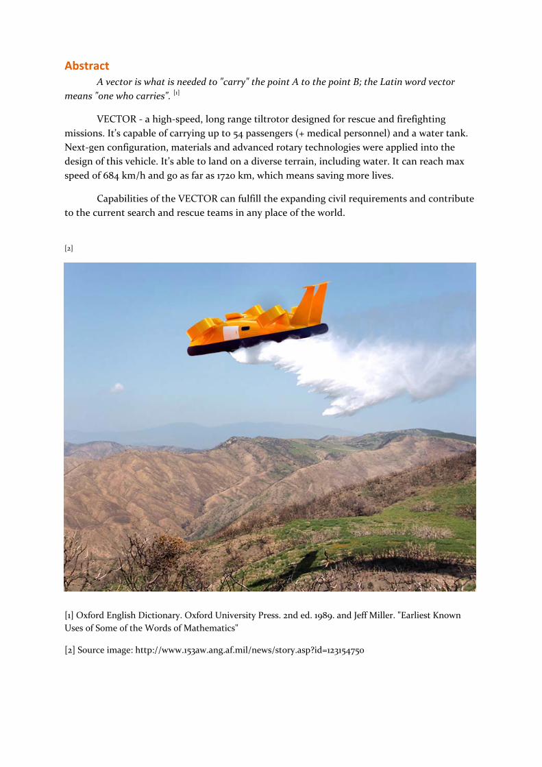
Abstract A vector is what is needed to "carry" the point A to the point B; the Latin word vector
means "one who carries". [1]
VECTOR ‐ a high‐speed, long range tiltrotor designed for rescue and firefighting
missions. It’s capable of carrying up to 54 passengers (+ medical personnel) and a water tank.
Next‐gen configuration, materials and advanced rotary technologies were applied into the
design of this vehicle. It’s able to land on a diverse terrain, including water. It can reach max
speed of 684 km/h and go as far as 1720 km, which means saving more lives.
Capabilities of the VECTOR can fulfill the expanding civil requirements and contribute
to the current search and rescue teams in any place of the world.
[2]
[1] Oxford English Dictionary. Oxford University Press. 2nd ed. 1989. and Jeff Miller. "Earliest Known
Uses of Some of the Words of Mathematics"
[2] Source image: http://www.153aw.ang.af.mil/news/story.asp?id=123154750

3
Table of Contents
1. Introduction ................................................................................................................................ 4
2. Objectives .................................................................................................................................... 5
3. Design .......................................................................................................................................... 5
A. General Design Approach ...................................................................................................... 5
B. Seating Configuration and Cabin Design .............................................................................. 7
C. Chassis Design ........................................................................................................................ 7
4. Propulsion ................................................................................................................................... 9
A. Power Estimation .................................................................................................................... 9
B. Engine Selection .................................................................................................................... 10
C. Ducted Fan Design ................................................................................................................. 11
D. Power Needed in Flight ......................................................................................................... 12
5. Aerodynamics ............................................................................................................................. 12
A. Computational Fluid Dynamics ............................................................................................ 12
B. Flow Characteristics .............................................................................................................. 15
6. Performance ............................................................................................................................... 17
A. Transportation Efficiency ...................................................................................................... 17
B. Weight Estimation ................................................................................................................. 18
C. Speed Estimation ................................................................................................................... 19
D. Stability Analysis .................................................................................................................... 19
E. Fuel and Range ....................................................................................................................... 23
7. Material Selection ..................................................................................................................... 24
8. Cost Analysis .............................................................................................................................. 25
9. Conclusion and Recommendations ......................................................................................... 26
References .......................................................................................................................................... 27
Bibliography ...................................................................................................................................... 28
Appendices ........................................................................................................................................ 29
Appendix A. Modelling Action of the Blades ........................................................................ 29
Appendix B. Stability Analysis ............................................................................................... 30
Appendix C. Longitudinal Dynamics ...................................................................................... 31
Appendix D. On‐water Stability Analysis ............................................................................... 33
4
Introduction This paper introduces the VECTOR ‐ a high‐speed, long range tiltrotor designed for
rescue and firefighting missions. It’s capable of carrying up to 54 passengers (+ medical
personnel) and a water tank. Next‐gen configuration, materials and advanced rotary
technologies were applied into the design of this tiltrotor. Capabilities of the VECTOR can
fulfill the expanding civil requirements and contribute to the current search and rescue teams
in any place of the world.
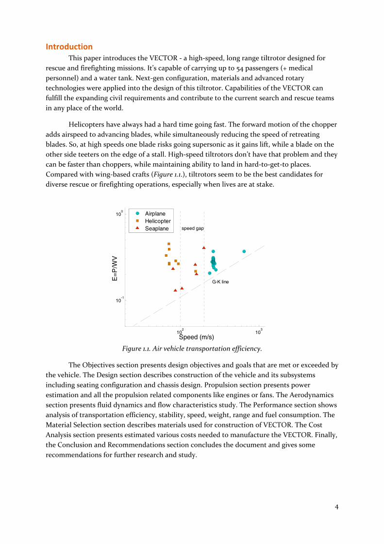
Helicopters have always had a hard time going fast. The forward motion of the chopper
adds airspeed to advancing blades, while simultaneously reducing the speed of retreating
blades. So, at high speeds one blade risks going supersonic as it gains lift, while a blade on the
other side teeters on the edge of a stall. High‐speed tiltrotors don’t have that problem and they
can be faster than choppers, while maintaining ability to land in hard‐to‐get‐to places.
Compared with wing‐based crafts (Figure 1.1.), tiltrotors seem to be the best candidates for
diverse rescue or firefighting operations, especially when lives are at stake.
Figure 1.1. Air vehicle transportation efficiency.
The Objectives section presents design objectives and goals that are met or exceeded by
the vehicle. The Design section describes construction of the vehicle and its subsystems
including seating configuration and chassis design. Propulsion section presents power
estimation and all the propulsion related components like engines or fans. The Aerodynamics
section presents fluid dynamics and flow characteristics study. The Performance section shows
analysis of transportation efficiency, stability, speed, weight, range and fuel consumption. The
Material Selection section describes materials used for construction of VECTOR. The Cost
Analysis section presents estimated various costs needed to manufacture the VECTOR. Finally,
the Conclusion and Recommendations section concludes the document and gives some
recommendations for further research and study.
102
103
10-1
100
Speed (m/s)
E=P
/WV
AirplaneHelicopterSeaplane
G-K line
speed gap

5
1. Objectives The team engineered the craft to meet and exceed all of the following design goals:
Cruise speed: 540 km/h
Range: 1480 km
Take‐off from water or ground; land on water or ground. Water includes lakes and
oceans
Carry up to 50 passengers
Ability to siphon water into an internal tank and expel water while airborne
Construction was based on field tested components and solutions to ensure the best possible
reliability and simplicity of the design.
2. Design
A. General Design Approach
To specify main characteristics the team performed rough estimation, based on
research on crafts like V‐22 Osprey, or Bell‐Boeing QTR. There was need to include new types
of materials, and to make sure that design meets the given objectives. Here are the main
conclusions:
Main characteristics:
Crew: two (pilot, copilot)
Capacity: 60 passengers or 14 tons cargo
Length: 12 m
Width without nozzles: 8 m
Height: 2.5 m
Disc area: 4 × 2.7 m²
Body area: 96 m² (top view)
Empty weight: 11 ton
Inside payload: 14 ton
Max takeoff weight: 30 tons
Powerplant: 4 × Honeywell's T55 engine, 4 × 3,631 kW
Performance:
Maximum speed: 190 m/s (684 km/h)
Cruise speed: 162 m/s at sea level
Power/mass: 484 kW/ ton
Lifting body was introduced to provide enough force to lift itself. Its layout is shown in
figure 2.1. The monocoque body has airfoil‐shaped section so as to provide good aerodynamics
and it is wide to give best possible in‐air and on‐water stability. Water tank is placed inside the
chassis to further improve the stability and weight distribution. Design introduces ducted
nozzles with contra‐rotating propellers resulting in high performance and low induced energy
loss. Searchlights attached on the front make looking for people easier and fluorescent orange

6
coating of the unibody ensures great visibility of the vehicle during rescue operations.
Figure 2.1. Rough body layout.
As a tiltrotor, the craft has characteristics of an airplane and a helicopter. In Cruise, it is more
like an airplane what ensures maximum power and efficiency. Horizontal tail and vertical tail
were also used to further improve stability.
Figure 2.2. 3D presentation of the VECTOR.
7
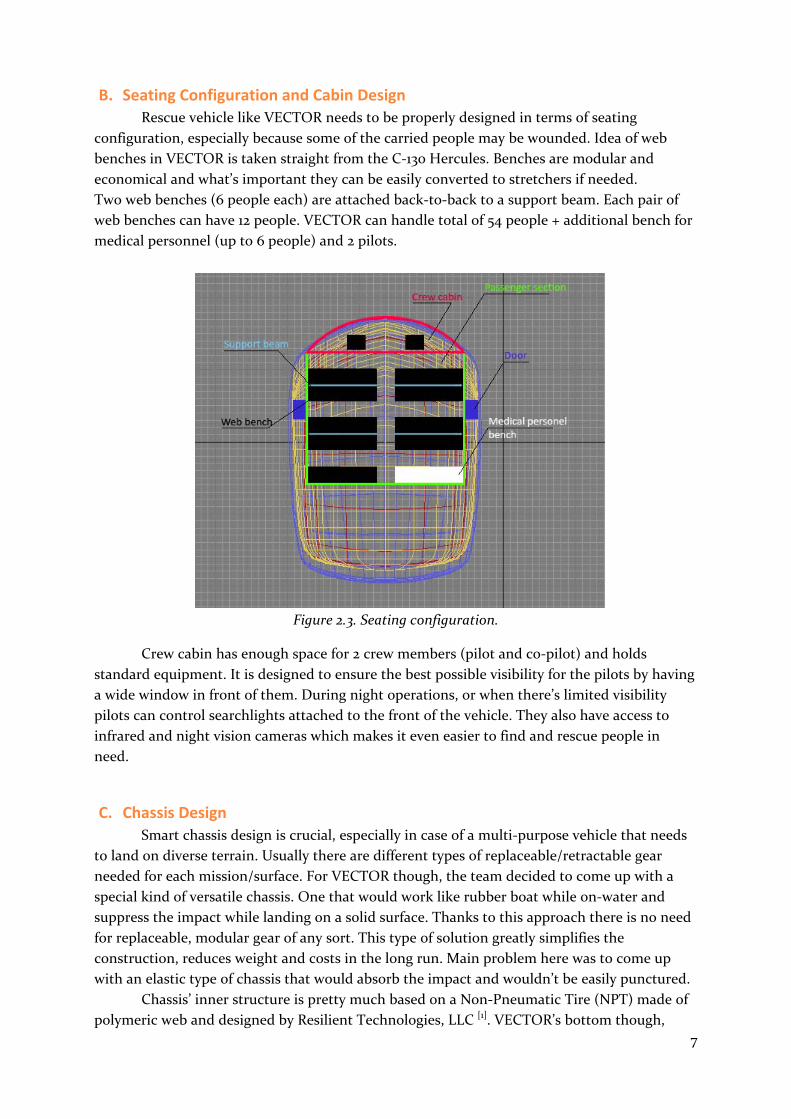
B. Seating Configuration and Cabin Design Rescue vehicle like VECTOR needs to be properly designed in terms of seating
configuration, especially because some of the carried people may be wounded. Idea of web
benches in VECTOR is taken straight from the C‐130 Hercules. Benches are modular and
economical and what’s important they can be easily converted to stretchers if needed.
Two web benches (6 people each) are attached back‐to‐back to a support beam. Each pair of
web benches can have 12 people. VECTOR can handle total of 54 people + additional bench for
medical personnel (up to 6 people) and 2 pilots.
Figure 2.3. Seating configuration.
Crew cabin has enough space for 2 crew members (pilot and co‐pilot) and holds
standard equipment. It is designed to ensure the best possible visibility for the pilots by having
a wide window in front of them. During night operations, or when there’s limited visibility
pilots can control searchlights attached to the front of the vehicle. They also have access to
infrared and night vision cameras which makes it even easier to find and rescue people in
need.
C. Chassis Design Smart chassis design is crucial, especially in case of a multi‐purpose vehicle that needs
to land on diverse terrain. Usually there are different types of replaceable/retractable gear
needed for each mission/surface. For VECTOR though, the team decided to come up with a
special kind of versatile chassis. One that would work like rubber boat while on‐water and
suppress the impact while landing on a solid surface. Thanks to this approach there is no need
for replaceable, modular gear of any sort. This type of solution greatly simplifies the
construction, reduces weight and costs in the long run. Main problem here was to come up
with an elastic type of chassis that would absorb the impact and wouldn’t be easily punctured.
Chassis’ inner structure is pretty much based on a Non‐Pneumatic Tire (NPT) made of
polymeric web and designed by Resilient Technologies, LLC [1]. VECTOR’s bottom though,

8
won’t be airless like in those tires and the structure will be closed instead. This is because air
sitting in the “tunnels” of the structure helps VECTOR’s buoyancy. Thanks to the polymer web
structure, body of the chassis is well reinforced and reliable. Even if there’s some structural
damage inflicted, vehicle’s bottom can still absorb impact from landing on a solid surface and
keep VECTOR on‐water without any problem. The chassis is additionally covered with a
special phenol coating as to protect it from high temperatures during the firefighting missions.
Water tank is embedded inside the chassis which gives good weight distribution, and
while the tank is empty it additionally helps to keep vehicle afloat. There is also a siphoning
system with an electric pump installed so that the crew can lower a retractable pipe to get
water inside the tank. To save the water and to enable more precise firefighting capabilities the
system allows segmented drops over multiple fires without landing.
Figure 2.4. Chassis prototype idea. [1]

9
3. Propulsion
A. Power Estimation
Targeted cruise status:
Speed: vcruise=155 m/s
Takeoff weight Wt= 25 tons
The ducted propeller efficiency is lower than that of open propeller. The total efficiency
of the current design is 0.7. According to CFD results, the designed T/W was estimated
based on L/D performance of the craft (equation (1) and shown in Figure 4.1.) The max T/W
happens at cruise and the T/W is 0.2685. Consequently, the total needed power of the engine
can be calculated by equation (2). It is about 14500 kW.
T/W= D/L (1)
T, thrust KN; W, 81.9tW kN.
enginecruise PvW
TW max)( (2)
Figure 4.1. Thrust to Weight ratio.
0 2 4 6 8 100.15
0.2
0.25
0.3
Angle of attack
T/w

10
B. Engine Selection
After researching about other similar crafts the team decided on Honeywell’s T55
turboshaft engine that possesses all the necessary characteristics. Very same engine is used in
CH‐47 Chinook heavy‐lift helicopter, which was field‐tested during many heavy‐duty military
missions all around the globe, in Vietnam, Falklands, Iraq and Afghanistan.
Engine Specifications[1]:
Engine type:
4 × Honeywell's T55 engine
General characteristics:
Type: Turboshaft
Length: 1,196.3 mm
Diameter: 615.9 mm
Dry weight: 377kg
Components:
Compressor: 7‐stage axial compressor and 1‐stage centrifugal compressor
Turbine: 2‐stage gas producer and 2‐stage free power
Performance:
Maximum power output: 4,867 shp (3,631 kW)
Total power: 4 × 3631 = 14524 kW
Figure 4.2. Engine sectional view. [2] Figure 4.3. Engine Air Flow diagram. [2]
11
C. Ducted Fan Design
A ducted fan is a propulsion arrangement whereby a fan, which is a type of propeller, is
mounted within a cylindrical shroud or duct. The duct reduces losses in thrust from the tip
vortices of the fan, and varying the cross‐section of the duct allows the designer to
advantageously affect the velocity and pressure of the airflow according to Bernoulli's
Principle. Ducted fan propulsion is used in aircraft, airboats, hovercraft and fan packs.
Advantages:
By reducing propeller blade tip losses and directing its thrust towards the back only,
the ducted fan is more efficient in producing thrust than a conventional propeller,
especially at higher rotational speeds.
By sizing the ductwork appropriately, the designer can adjust the air velocity through
the fan to allow it to operate more efficiently at higher air speeds than a propeller
would.
For the same static thrust, a ducted fan has a smaller diameter than a free propeller.
Ducted fans are quieter than propellers: they shield the blade noise, and reduce the tip
speed and intensity of the tip vortices both of which contribute to noise production.
Ducted fans can allow for a limited amount of thrust vectoring, something normal
propellers are not well suited for. This allows them to be used instead of tiltrotors in
some applications.
Disadvantages:
Good efficiency requires very small clearance between blade tips and the duct.
Ducts are heavy and expensive.
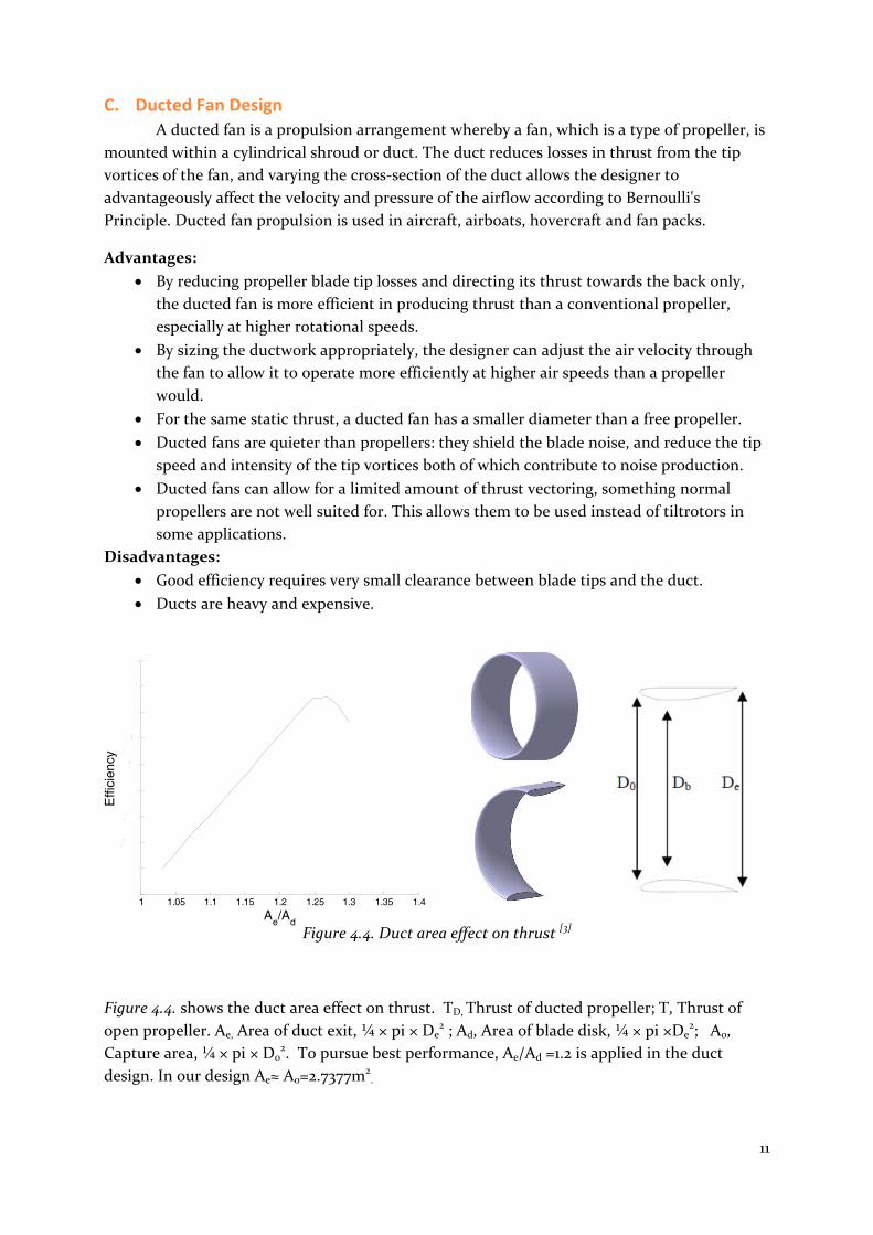
Figure 4.4. Duct area effect on thrust [3]
Figure 4.4. shows the duct area effect on thrust. TD, Thrust of ducted propeller; T, Thrust of
open propeller. Ae, Area of duct exit, ¼ × pi × De2 ; Ad, Area of blade disk, ¼ × pi ×De
2; A0,
Capture area, ¼ × pi × D02. To pursue best performance, Ae/Ad =1.2 is applied in the duct
design. In our design Ae≈ A0=2.7377m2.
1 1.05 1.1 1.15 1.2 1.25 1.3 1.35 1.40.5
0.52
0.54
0.56
0.58
0.6
0.62
0.64
0.66
0.68
Ae/Ad
Effi
cien
cy

12
D. Power Needed in Flight
As the craft can be lifted by itself, the needed power in cruise can be calculated based
on drag performance (equation 3). Figure 4.5. shows the needed power for cruise with varying
speed and angle of attack.
The available power for thrust is engineavailable PP = 10100 kW.
1000/
2
1 3Dneed sCvP (kW) (3)
Figure 4.5. Power needed in cruise.
The engine performance is clearly described in Figure 4.5. with different speed and
angle of attack. This figure also gives an advice for operation.
4. Aerodynamics
A. Computational Fluid Dynamics
The aerodynamic performance was studied by using Computational Fluid Dynamics
method (CFD). A simplified half‐model was employed into numerical simulation, owing to
symmetry of the geometry (Figure 5.1.). Nozzles were omitted in CFD study, no propulsion
system was employed into the numerical simulations. The structured‐unstructured hybrid grid
method was applied to the simulations. Hybrid grid methods are designed to take advantage of
the positive aspects of both structured and unstructured grids. Structured grid was specified in
the bulk of the domain, and unstructured grid in local regions for complex craft geometry. For
resolution of turbulent boundary layer profiles, a wall normal spacing of 2.0e‐4 of the mean
aerodynamic chord was used for craft; an average y+ value of 200 for craft was achieved. Ten
layers of cells were clustered towards the walls with a growth ratio of 1.2 in the wall normal
0 50 100 150 2000
5000
10000
15000
Speed (m/s)
Pow
er (k
w)
=10o=5o
=0oPavailable

13
direction. The total number of cells was approximately 2.5 million. The numerical simulations
were conducted at a Reynolds number, based on the mean chord length of the main wing, of
6×10⁷. The use of computational fluid dynamics codes to simulate the flow around
geometrically complicated shapes such as airplanes, cars and ships has become standard
engineering practice in the last few years. A number of commercially available codes can be
used to perform these studies. The finite volume codes FLUENT[1] was employed in the present
study. It has been performing well in aerodynamic prediction for craft[2].
Figure 5.1. Model in simulation. Figure 5.2. Surface grids.
The governing equations are the incompressible Reynolds‐averaged Navier‐Stokes equations
for continuity and momentum:
0
i
i
x
U (1)
j
jii
x
UU
t
U
)(
)(1 ''
2
jijjj
i
i
uuxxx
U
x
P
(2)
where ''jiuu is the Reynolds stress term. The realizable turbulence model[3] is used. The
transport equations of and are written as,
kMbkjk
t
jj
j
SYGGx
k
xku
xk
t
)()()( (3)
SGC
kC
kCSC
xxu
xt bj
t
jj
j
31
2
21)()()( (4)
This turbulence model has been extensively validated and well behaved for a wide
range of flows, including rotating homogeneous shear flows, free flows including jets and

14
mixing layers, channel and boundary layer flows, and separated flows. The incompressible
Navier‐Stokes equations, Eq. (1) and Eq. (2), are solved by the SIMPLE algorithm with a
second‐order upwind scheme applied to the convection terms.
Figure 5.3. Aerodynamics of the craft.
Figure 5.3. presents the CFD results. The center of gravity is placed at 1/4 mean chord length. It
can be seen that the craft has max L/D at 5 .
Also, we can get:
0286.0LC (angle of attack degree)
002065.0mC (angle of attack degree)
L/Dmax = 5.823
0 2 4 6 8 100.02
0.03
0.04
0.05
0.06
0.07
0.08
Angle of attack
CD
0 2 4 6 8 100.05
0.1
0.15
0.2
0.25
0.3
0.35
0.4
Angle of attackC
L
0 2 4 6 8 103.5
4
4.5
5
5.5
6
Angle of attack
L/D
0 2 4 6 8 10-0.02
-0.018
-0.016
-0.014
-0.012
-0.01
-0.008
-0.006
-0.004
-0.002
0
Angle of attack
Cm
15
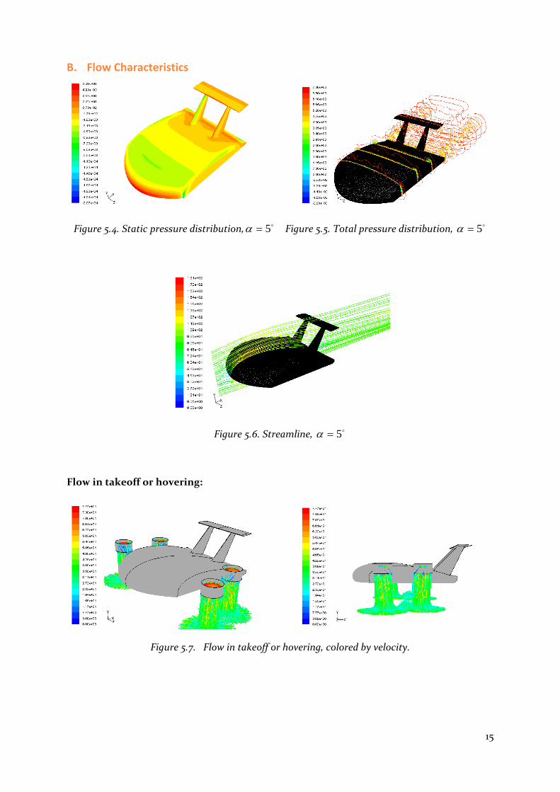
B. Flow Characteristics
Figure 5.4. Static pressure distribution, 5 Figure 5.5. Total pressure distribution, 5
Figure 5.6. Streamline, 5
Flow in takeoff or hovering:
Figure 5.7. Flow in takeoff or hovering, colored by velocity.

16
Flow in cruise:
Figure 5.8. Flow in cruise, colored by velocity.

17
5. Performance
A. Transportation Efficiency
In the following part, the transportation efficiency of VECTOR was compared with
some high speed helicopters. Giuseppe Gabrielli and Theodore Von Karman defined the
specific resistance of a vehicle[1,2], E, as maximum motor output power P, divided by total
weight W multiplied by maximum speed Vmax.
E=P/WVmax (1)
The lower value of E means higher transportation efficiency. The transportation
characteristic Wp/W presents the effective capacity of craft. In order to describe the
transportation performance in high speed, the payload weight Wp is specified with the max
inside payload. The results are shown below.
By Figure 6.1., we can see that the specific resistance of VECTOR is a bit high, although
it can reach very high speed. This is attributed to the propeller system utilized in VECTOR, the
ducted propeller. The efficiency of ducted propeller is lower than that of open propeller. Figure
6.2. tells another story that the VECTOR has a high capacity in high speed. That means the
VECTOR has more effective payload, furthermore it can carry this payload cruise in very high
speed. This is exactly what we want.
Figure 6.1. Specific resistance of some high speed helicopters.
Figure 6.2. Relative capacity in high speed.
Conclusions:
As for transportation, the VECTOR has:
a) Outstanding speed performance.
b) Excellent payload capacity in high speed.
c) Considerable fuel efficiency.
60 80 100 120 140 160 180 2000.2
0.22
0.24
0.26
0.28
0.3
0.32
0.34
Max speed (m/s)
E
Canadair CL-84Sikorsky X2AH-56 CheyennePiasecki X-49V-22 OspreyVECTOR
60 80 100 120 140 160 180 2000.1
0.15
0.2
0.25
0.3
0.35
0.4
0.45
0.5
Max speed (m/s)
Wp/W
Canadair CL-84AH-56 CheyennePiasecki X-49V-22 OspreyVECTOR

18
B. Weight Estimation
Takeoff weight estimation:
Figure 6.3. presents the takeoff weight and total power of helicopter. For the current
design, the effective power comparing with conventional helicopter is Pengine* = 10100 kW. It is
found in the figure that the current design can be specified with a takeoff weight of 30 ton.
Figure 6.3. Takeoff weight and power
Inside payload Wp estimation:
It is specified for the craft that the lift to drag ratio in cruise is L/D= 5.823. The lift can
be calculated by:
cruiseDL 823.5 (2)
By equations 2 and 4, we have L= 364.8 kN. That is about 37 tons. It is estimated above
that the max takeoff weight is 30 tons, so the craft can cruise with 30 tones. If the empty
weight We is given, then the inside payload Wp depends on the effective space in craft or 30‐
We.
Effective cargo space of VECTOR estimation:
Volume = 6m × 8m × effective height = 6 × 8 × 1.5 = 72m3
Effective cargo space for QTR / C‐130 Hercules[3,4]: 12.5 × 2.7 × 3m3 = 101.25m3
Payload of QTR / C‐130 Hercules: 20 tons
So, the cargo for VECTOR will be: 20 × 72 / 101.25 = 14 tons
The inside payload is Wp = 14 tons (includes 5 tons of water in the tank and 60 passengers)
Based on these calculations the empty weight can vary between 8‐12 tons or more.
0 5 10 15 20 25 30 350
2000
4000
6000
8000
10000
12000
Takeoff Weight (ton)
Pow
er (K
W)

19
C. Speed Estimation
Cruise speed cruisev estimation:
The max L/D happens at angle of attack 5 degrees, L/D= 5.823. Cruise in this status, the
craft achieves the most efficient flight.
Thrust availableT can be provided by engine: enginecruiseavailable PvT (3)
Drag cruiseD in cruise based on CFD results: Dcruisecruise sCvD 2
2
1 (4)
Thrust meets drag: cruiseavailable DT (5)
By equations 3‐5, we have 162cruisev m/s
Maximum cruise speed maxv estimation:
Thrust in max cruise speed: enginePvT max (6)
Min drag at zero angle of attack: DsCvD 2max2
1 (7)
For max speed, T=D. So, maxv = 190 m/s.
D. Stability Analysis
Aircraft longitudinal and lateral flight dynamics are described by a set of 6 Degree of
Freedom (DOF) non linear differential Equations of Motion (EOM). The EOM are based on
Newton’s second law for the behavior of a free body in 3 dimensional space under the influence
of external forces. This paper restricts itself to the longitudinal dynamics which can be
decoupled and modeled separately from the lateral case.
Figure 6.4. Stability axes and body axes.

20
Static Longitudinal Stability:
Longitudinal static stability is the stability of an aircraft in the longitudinal, or pitching,
plane during static (established) conditions. This characteristic is important in determining
whether an aircraft will be able to fly as intended. The stability axes are shown in Figure 6.4.
If an aircraft is longitudinally stable, a small increase in angle of attack will cause the
pitching moment on the aircraft to change so that the angle of attack decreases. Similarly, a
small decrease in angle of attack will cause the pitching moment to change so that the angle of
attack increases. That is,
0
L
m
C
C (8)
As for all airplanes, the lift increases with increase of angle of attack, 0
LC, then a
longitudinal static stable airplane must be,
0
mC (9)
Equation 9 is the condition of longitudinal static stability for airplane. It is sensitive to position
for center of gravity. From the CFD study, it is clear that the current project is static stable and
the location of center of gravity (1/4 chord) is rational.
For trim, we also need:
0mC (10)
By CFD we can get mC and mtC . mC is pitch moment derivative for craft, mtC is pitch
moment derivatives of tail. Then,
emtmmm CCCC 0 =0 (11)
e is the elevator deflection angle. Moment trim can be achieved by control the elevator
deflection angle (equation 11).
Longitudinal Dynamics:
Newton’s second law requires that the sum of all external forces acting on the aircraft
be equal to the time derivative of its momentum. To simplify the analysis, the Newtonian
vector equations are recast in scalar form consisting of 3 force and 3 moment equations.
Due to the complexity of the non linear EOM, it becomes necessary to linearize the
equations. The linearization is based on perturbation theory with the assumption that the
aircraft is flying in an equilibrium condition.
21
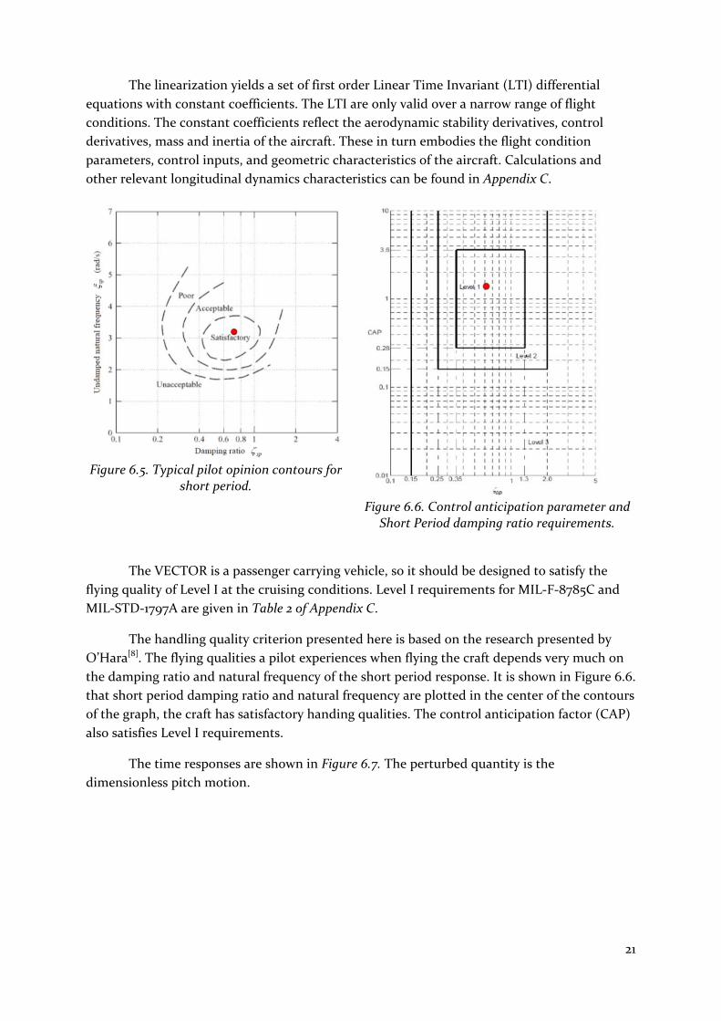
The linearization yields a set of first order Linear Time Invariant (LTI) differential
equations with constant coefficients. The LTI are only valid over a narrow range of flight
conditions. The constant coefficients reflect the aerodynamic stability derivatives, control
derivatives, mass and inertia of the aircraft. These in turn embodies the flight condition
parameters, control inputs, and geometric characteristics of the aircraft. Calculations and
other relevant longitudinal dynamics characteristics can be found in Appendix C.
Figure 6.5. Typical pilot opinion contours for short period.
Figure 6.6. Control anticipation parameter and Short Period damping ratio requirements.
The VECTOR is a passenger carrying vehicle, so it should be designed to satisfy the
flying quality of Level I at the cruising conditions. Level I requirements for MIL‐F‐8785C and
MIL‐STD‐1797A are given in Table 2 of Appendix C.
The handling quality criterion presented here is based on the research presented by
O’Hara[8]. The flying qualities a pilot experiences when flying the craft depends very much on
the damping ratio and natural frequency of the short period response. It is shown in Figure 6.6.
that short period damping ratio and natural frequency are plotted in the center of the contours
of the graph, the craft has satisfactory handing qualities. The control anticipation factor (CAP)
also satisfies Level I requirements.
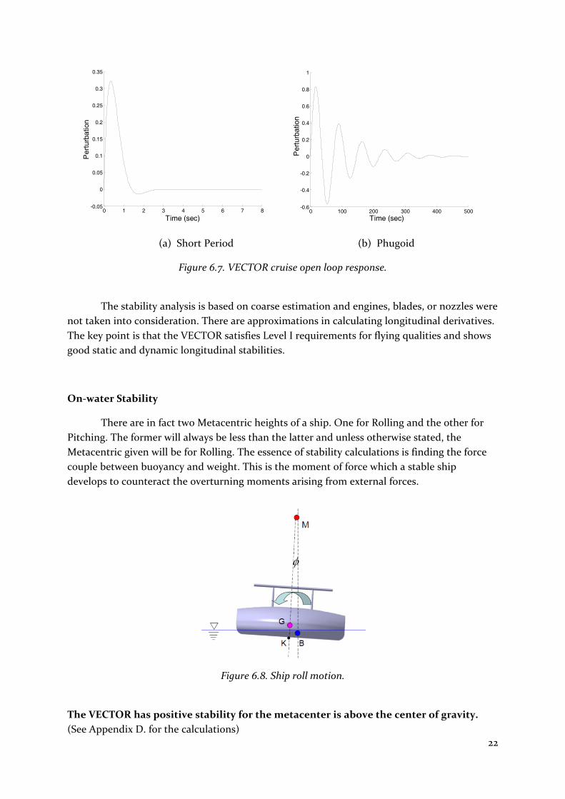
The time responses are shown in Figure 6.7. The perturbed quantity is the
dimensionless pitch motion.
22
(a) Short Period (b) Phugoid
Figure 6.7. VECTOR cruise open loop response.
The stability analysis is based on coarse estimation and engines, blades, or nozzles were
not taken into consideration. There are approximations in calculating longitudinal derivatives.
The key point is that the VECTOR satisfies Level I requirements for flying qualities and shows
good static and dynamic longitudinal stabilities.
On‐water Stability
There are in fact two Metacentric heights of a ship. One for Rolling and the other for
Pitching. The former will always be less than the latter and unless otherwise stated, the
Metacentric given will be for Rolling. The essence of stability calculations is finding the force
couple between buoyancy and weight. This is the moment of force which a stable ship
develops to counteract the overturning moments arising from external forces.
Figure 6.8. Ship roll motion.
The VECTOR has positive stability for the metacenter is above the center of gravity.
(See Appendix D. for the calculations)
0 1 2 3 4 5 6 7 8-0.05
0
0.05
0.1
0.15
0.2
0.25
0.3
0.35
Time (sec)
Per
turb
atio
n
0 100 200 300 400 500-0.6
-0.4
-0.2
0
0.2
0.4
0.6
0.8
1
Time (sec)
Per
turb
atio
n
23
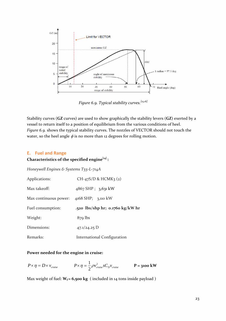
Figure 6.9. Typical stability curves.[15,16]
Stability curves (GZ curves) are used to show graphically the stability levers (GZ) exerted by a
vessel to return itself to a position of equilibrium from the various conditions of heel.
Figure 6.9. shows the typical stability curves. The nozzles of VECTOR should not touch the
water, so the heel angle is no more than 12 degrees for rolling motion.
E. Fuel and Range
Characteristics of the specified engine[14] :
Honeywell Engines & Systems T55‐L‐714A
Applications: CH‐47S/D & HCMK3 (2)
Max takeoff: 4867 SHP ; 3,631 kW
Max continuous power: 4168 SHP; 3,110 kW
Fuel consumption: .520 lbs/shp hr; 0.1760 kg/kW hr
Weight: 879 lbs
Dimensions: 47.1/24.25 D
Remarks: International Configuration
Power needed for the engine in cruise:
cruisevDP cruiseDcruise vsCvP 2
2
1 P = 3100 kW
Max weight of fuel: Wf = 6,500 kg ( included in 14 tons inside payload )

24
Range: tvL cruise tPWf
1760.04 L = 1720 km
6. Material Selection Material selection is being a very important part of the whole design process. A
rotocraft used for rescue missions has to be able to work in various, possibly hazardous
conditions (high temperature or moisture). To make sure the vehicle is safe and reliable, it
needs to be constructed using carefully chosen and well tested materials.
The team decided to use composites for vast majority of the construction, particularly
CRP (Carbon fiber‐Reinforced Plastics) and FRP (Fiberglass Reinforced Plastics). Main reason
for this choice was significant reduction of weight, ability to use much simpler moulded parts
and resistance to fire. Comparing to widely used aluminum, composites have stronger
structure, are lighter, cheaper, faster and easier to manufacture. Moreover, they have already
been field‐tested. Composites have proven to be highly successful in the field of aeronautics
numerous of times and much of the fuselage of aircrafts like Boeing 787 Dreamliner or Airbus
A350 XWB is made of them.
For example, here are some advantages over a traditional rudder made from sheet aluminum
for Airbus A310[1]:
25% reduction in weight
95% reduction in components by combining parts and forms into simpler moulded
parts.
Overall reduction in production and operational costs, economy of parts results in
lower production costs and the weight savings create fuel savings that lower the
operational costs of flying the aeroplane.
FRP and CRP are corrosion resistant which is great for a vehicle that’s going to have
much contact with water. All the VECTOR’s surfaces exposed to high temperatures (eg. during
firefighting missions) are also insulated with phenol which posseses superior fire protection
and retardancy habits. Some specially filled phenol resins exhibit fire retardancy features up to
5000 ºC [2].
The advantages of phenol laminates[2]:
no auto‐propagation of flame
very low smoke development (lowest possible)
very low toxic fume emission (almost not measurable)
low heat release
no release of flammable vapor
very low loss of strength at high operating temperatures up to 200 ºC
low thermal conductivity
Polymers have almost infinite lifespan, but they’re also recyclable. They can be

25
thermally decomposed in a one‐step process and carbon fiber can be reclaimed. Then they can
be reused in e.g. consumer electronics [3].
7. Cost Analysis For the cost analysis the team used on‐line NASA Cost Estimating Web Site, and
particularly the Airframe Cost Model. The airframe cost refers to the cost of the assembled
structural and aerodynamic components of the air vehicle and not just the basic structure [1].
The analysis was based on the assumption that 100 tiltrotors were manufactured (excluding 3
test flight vehicles).
Table 1. Airframe Cost Model for the VECTOR.
Hours (K)
Cost (M04$)
Non‐Recurring Costs
Engineering 3339 395
Tooling 1879 194
Development Support
98
Flight Test 28
Subtotal non‐recurring
5218 715
Recurring Costs
Engineering 1526 181
Tooling 1132 117
Manufacturing 8975 869
Material 311
Quality Assurance 1194 115
Subtotal recurring 12827 1593
Total 18045 2308
Note that costs may be higher due to some advanced materials (composites, polymers) and
technologies (chassis prototype) used.

26
8. Conclusion and Recommendations Today, rotary crafts are broadly used in transportation, construction, firefighting,
search and rescue, et al for its operating characteristics. The increasing demand for more
efficient rotorcraft in rescue promotes the design of VECTOR. Next‐gen configuration,
materials and advanced rotary technologies were applied into the design of this tiltrotor.
Capabilities of VECTOR can fulfill the expanding civil requirements and contribute to the
current search and rescue teams in any place of the world.
The concept of self‐lifting was introduced into fuselage design. Large and airfoil‐shaped
body provides not only the lift, with which 30 ton weight is hovered, but also on‐water and in‐
air stability and spacious cabin for the passengers (including the injured ones). To meet the
speed requirements for mission, rotary systems help the VECTOR cove the speed. Contra‐
rotating ducted propellers take the place of open propellers considering harsh operating
conditions, such as cruise approaching the ocean surface in very high speed. Tail as stabilizer
like in a conventional airplane shows good performance for stability of the VECTOR. As the
VECTOR behaves like an airplane in cruise, control of flight could be based on sophisticated
control strategy of the airplane.
With streamlined fuselage design made of light, strong composites and powerful
engines the VECTOR can operate in ample speed, which means quicker ability to rescue more
people at once and fewer families suffering from pain of losing their loved ones. Fluorescent
orange body coating ensures great visibility of the vehicle during the rescue operations.
Innovative multi‐terrain chassis and ability to perform segmented drops over multiple fires
without landing gives versatility, necessary precision and reduces the costs. Simplicity of the
design guarantees higher reliability
The unique and well‐thought design makes VECTOR show outstanding performance in
transportation efficiency. The VECTOR is supposed to meet the needs of efficiency,
productivity, versatility and to ensure that life and safety comes first.
Optional recommendations
The VECTOR is an efficient and economical combination of a tiltrotor and a wing‐
shaped craft, which is reflected in its technologies and characteristics. The team explored
potential benefits of the design and found that some level of refinement and further study,
especially on the multipurpose chassis could be done and may further improve the craft. Here
are some recommendations for further research:
Testing performance under harsh operating conditions such as over waves.
Refining the fuselage considering complex flow.
Conducting a more detailed noise analysis.
Conducting an aerodynamic study with engine, nozzle and propeller.
Putting focus on environmental friendliness.

27
References Design Phase
[1] http://www.markstechnologynews.com/2008/11/honeycomb‐tire‐bomb‐proof‐bullet‐
proof.html
Propulsion
[1] Gunston, Bill (2006). World Encyclopedia of Aero Engines, 5th Edition. Phoenix Mill,
Gloucestershire, England, UK: Sutton Publishing Limited.
[2] http://www.chinook‐helicopter.com/standards/areas/engine.html
[3] Ducted Propeller Study[R]. AD ‐ 647299, 1964.
Aerodynamics
[1] FLUENT6.2 User Guide, Fluent Inc, 2005.
[2] Scheidegger T. 3rd AIAA CFD Drag Prediction Workshop, Part 1: DLRF6/F6‐FX2B. Report,
San Francisco 2006.
[3] T.‐H. Shih, W.W. Liou, A. Shabbir, Z. Yang, and J. Zhu. A New Eddy‐Viscosity Model for
High Reynolds Number Turbulent Flows – Model Development and Validation. Computers
Fluids, 1995, 24(3): 227‐238.
Performance
[1] Gabrielli, G. and von Karman, Th., What price speed? Specific power required for
propulsion of vehicles, Mechanical Engineering, Vol 72, 1950, pp. 775‐781.
[2] Teitler, S. and Proodian, R.E., “What Price Speed, Revisted,” J. Energy, Vol 4, No 1, 1980, pp.
46‐48.
[3] C‐130 Hercules Overview,
http://www.fas.org/programs/ssp/man/uswpns/air/cargo/c130.html
[4] USAF C‐130 Hercules fact sheet. USAF, Ocrober 2009.
http://www.af.mil/information/factsheets/factsheet.asp?id=92
[5] Nelson, R., Flight Stability and Automatic Control, McGraw Hill, 1998.
[6] Etkin, B., and Reid, L., Dynamics of Flight: Stability and Control, J. Wiley & Sons, 1996.
[7] MIT open course‐ Aerospace Dynamics.
http://ocw.mit.edu/OcwWeb/Aeronautics‐and‐Astronautics/16‐61Aerospace‐
DynamicsSpring2003/LectureNotes/index.htm
[8] O'Hara, F. Handling criteria. Journal of Royal Aeronautical Society, 1967, Vol. 71, No. 676,
pp. 271‐291.
[9] Ship Stability. Kemp & Young. ISBN 0853090424
[10] Comstock, John (1967). Principles of Naval Architecture. New York: Society of Naval
Architects and Marine Engineers. pp. 827. ISBN 670020738.
[11] Harland, John (1984). Seamanship in the age of sail. London: Conway Maritime Press.
pp. 43. ISBN 0851771793.
[12] U.S. Coast Guard Technical computer program support accessed 20 December 2006.
[13] Lewis, Edward V. Principles of Naval Architecture (Second Revision), Volume I ‐
Stability and Strength. Society of Naval Architects and Marine Engineers (SNAME).
[14] Engine Manufacturers, Helicopter Annual 2009, P 57‐63.

28
[15] Rawson K.J. and Tupper E.C., Basic Ship Theory Fifth Edition, Reprinted, 2002.
[16] Derret D.R., Ship Stability for Masters and Mates Fourth Edition,
Butterworth‐heinemann Ltd, 1990.
Material Selection
[1] http://en.wikipedia.org/wiki/Fibre‐reinforced_plastic
[2] http://www.unitedcomposites.net/engelsepaginas/fireretardantcomposites.htm
[3] http://en.wikipedia.org/wiki/Carbon‐fiber_reinforced_plastic
Cost Analysis
[1] http://cost.jsc.nasa.gov/airframe.html
Bibliography 1. Antonio Filippone, University of Manchester
Flight Performance of Fixed and Rotary Wing Aircraft
2006 AIAA Education Series
2. Richard Bielawa, Rensselaer Polytechnic Institute, Troy, NY
Rotary Wing Structural Dynamics and Aeroelasticity, Second Edition
2006 AIAA Education Series
3. ALBERS, JAMES A., NASA, Ames Research Center, Moffett Field, CA
NASA rotorcraft technology for the 21st century
AHS, and ASEE, Aircraft Design, Systems and Operations Conference, Seattle, WA, July 31‐
Aug 2, 1989. 23 p.
4. Donald Kunz, Air Force Institute of Technology, Wright‐Patterson AFB, OH
Comprehensive Rotorcraft Analysis: Past, Present, and Future
46th AIAA/ASME/ASCE/AHS/ASC Structures, Structural Dynamics and Materials
Conference , Austin, Texas, Apr. 18‐21, 2005
5. Peretz Friedmann , University of Michigan
Rotary‐Wing Aeroelasticity: Current Status and Future Trends
Journal of Aircraft 1977 0021‐8669 vol.14 no.11 (1027‐1041)
6. FRIEDMANN, PERETZ P., California, University, Los Angeles
Rotary‐wing aeroelasticity with application to VTOL vehicles
IN: AIAA/ASME/ASCE/AHS/ASC Structures, Structural Dynamics and Materials
Conference, 31st, Long Beach, CA, Apr 2‐4, 1990, Technical Papers. Part 3 (A90‐29359 11‐
39). Washington, DC, American Institute of Aeronautics and Astronautics, 1990, p. 1624‐
1670.
7. LOWSON, M. V., Westland Helicopters, Ltd., Yeovil, Somerset, England; BALMFORD, D.
E. H., Westland Helicopters, Ltd., Yeovil, Somerset, England
Future advanced technology rotorcraft
In: Atlantic Aeronautical Conference, Williamsburg, Va., March 26‐28, 1979, Technical
Papers. (A79‐27351 10‐05) New York, American Institute of Aeronautics and Astronautics,
Inc., 1979, p. 146‐157.
8. Caradonna, Francis X., U.S. Army, Aviation and Missile Command, Moffett Field, CA
Developments and challenges in rotorcraft aerodynamics
Aerospace Sciences Meeting and Exhibit, 38th, Reno, NV, Jan. 10‐13, 2000

29
9. WARD, JOHN F., Ward Associates, Easton, MD
The design challenge of applying tiltrotor technology to the civil mission
AHS, and ASEE, Aircraft Design, Systems and Operations Conference, Seattle, WA, July 31‐
Aug 2, 1989. 12 p.
10. Reber, Ron R., Bell Helicopter Textron, Inc., Fort Worth, TX
Civil tiltrotor transportation for the 21st century
International Powered Lift Conference, Santa Clara, CA, Dec 1‐3, 1993
Appendices
Appendix A. Modelling Action of the Blades
It can be considered that the blade accelerates the oncoming flow. Or in other words,
the momentum for the air is increased by blade. From this point of view, we can model the
action of blade with momentum source in duct.
Fig. 1 Jet modeled by momentum source.
The duct geometry has two chords length for width. Implementing a momentum source
allows control of the added momentum distribution in the duct as opposed to the velocity
distribution. The total momentum flow is approximated by integration of momentum flux
across the duct,
2/
2/
2d
d
jetdsUM (1)
Ujet is the time‐average jet velocity at the jet exit, d is the duct width, and ds is a differential
distance across the jet exit. The momentum source distribution is calibrated to produce a
nearly uniform exit velocity profile. A User Defined Function (UDF) is used to apply the
momentum source to the correct cells in FLUENT.
Oncoming flow Jet
Momentum source

30
Appendix B. Stability Analysis
Flight conditions:
U=160 m/s cruise speed
g=9.81 N/kg
c=11.875 m mean chord
s= 95 m2 reference wing area ( body area, top view)
st=10.24 m2 area of tail
Q= 1.6074e+004 Pa dynamic pressure
m= 300,000 kg
Iy= 200,000 kg﹒m2
CD0=0.036
CL0=0.2083
Moment of inertia estimation:
WbkI xx22
)(96.0 zxy III
WlkI zz22
xk , zk , Correlation coefficient. 1.0xk , zk =0.21. b,width of craft body, l, length of craft body,
W, weight.
Longitudinal derivatives:
UQscCM mw /
UQscs
sM t
tq /
2
1 2 , ts , area of tail, t , tail lift curve slope.
g
UZn w
mU
QsCCZ DL
w
)2(
31
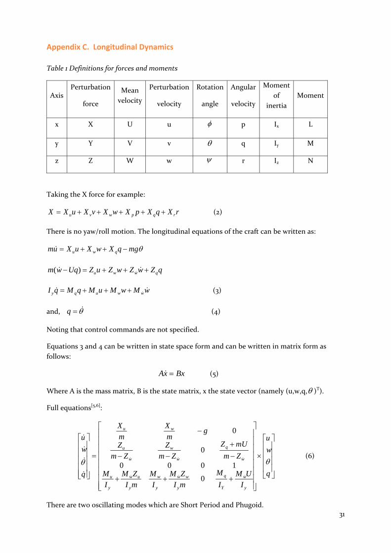
Appendix C. Longitudinal Dynamics
Table 1 Definitions for forces and moments
Axis Perturbation
force
Mean
velocity
Perturbation
velocity
Rotation
angle
Angular
velocity
Moment
of
inertia
Moment
x X U u p Ix L
y Y V v q Iy M
z Z W w r Iz N
Taking the X force for example:
rXqXpXwXvXuXX rqpwvu (2)
There is no yaw/roll motion. The longitudinal equations of the craft can be written as:
mgqXwXuXum qwu
qZwZwZuZUqwm qwwu )(
wMwMuMqMqI wwuqy (3)
and, q (4)
Noting that control commands are not specified.
Equations 3 and 4 can be written in state space form and can be written in matrix form as
follows:
BxxA (5)
Where A is the mass matrix, B is the state matrix, x the state vector (namely (u,w,q, )T).
Full equations[5,6]:
q
w
u
I
UM
I
M
mI
ZM
I
M
mI
ZM
I
M
Zm
mUZ
Zm
Z
Zm
Z
gm
X
m
X
q
w
u
y
w
Y
q
y
ww
y
w
y
uw
y
u
w
q
w
w
w
u
wu
0
1000
0
0
(6)
There are two oscillating modes which are Short Period and Phugoid.
32
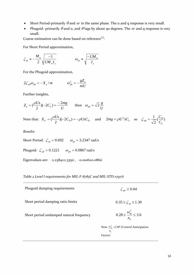
Short Period‐primarily and in the same phase. The u and q response is very small.
Phugoid‐ primarily and u, and lags by about 90 degrees. The and q response is very small.
Coarse estimation can be done based on reference[7]:
For Short Period approximation,
yw
qsp IUM
M 1
2
y
wsp I
UM
For the Phugoid approximation,
mXuphph /2 mU
gZuph 2
Further insights,
U
mgC
UsZ Lu
2)2)(
2(
then
U
gph 2
Note that: DDU UsCCUs
X )2)(
2( and LsCUmg 22 so )(
2
1
L
Dph C
C
Results:
Short Period: 692.0sp 2347.3sp rad/s
Phugoid: 1221.0ph 0867.0ph rad/s
Eigenvalues are: ‐2.2384±2.3351i , ‐0.0106±0.0861i
Table 2 Level I requirements for MIL‐F‐8785C and MIL‐STD‐1797A
Phugoid damping requirements
Short period damping ratio limits
Short period undamped natural frequency
04.0ph
30.135.0 sp
6.328.02
n
sp
Note
n
sp2: CAP (Control Anticipation
Factor)

33
Appendix D. On‐water Stability Analysis
G, center of gravity
B, center of buoyancy
M, metacenter
K, keel
= Angle of Heel
BM = Metacentric Radius
GM = Metacentric Height
GZ = Righting Lever measured from G
KB = Height of Center of Buoyancy from keel
KG = Height of Center of Gravity from keel
KM = Height of Metacenter from keel
Density for ocean surface water: 1026kg/m3
Density for water: 1000 kg/m3
It is nearly the same. So, we use 1000 kg/m3
3
12
1LBI , 2nd moment of the free surface about the centre line
water
WV
, Volume of the Tank [m3]
V
IBM
KM=KB+BM
KM=KG+GM
sinGMGZ (0 ‐10 degrees)
From the configuration of the body, we have KB=0.16 m, KG=1.0 m.
Then, GM= 16.2 m