Design of a UHBR Through Flow Nacelle for High Speed Stall ...
10
DESIGN OF A UHBR THROUGH FLOW NACELLE FOR HIGH SPEED STALL WIND TUNNEL INVESTIGATIONS S. Spinner * , R. Rudnik * * DLR, Institute of Aerodynamics and Flow Technologies, Braunschweig, Germany Abstract The design of a new through flow nacelle for the Airbus XRF1 wind tunnel model is presented. The nacelle is representative of a modern UHBR turbofan engine for long range transport aircraft and was especially designed to investigate the interaction of buffet phenomena on the wing lower side, pylon and nacelle within the research unit FOR 2895. During the design process the performance of the through flow nacelle was evaluated by performing RANS simulations with the DLR TAU code using Spalart-Allmaras as well as Reynolds- Stress turbulence models. For the initial nacelle design simulations of the isolated nacelle were performed. Having obtained an initial nacelle shape, it was integrated in the XRF1 CAD model. A pylon geometry was designed and a baseline nacelle position and orientation was defined. The numerical simulations proved the configuration with nacelle and pylon shows adequate performance under cruise conditions without exhibiting unusual adverse effects on the aircraft. As intended, significant shock induced separations were observed on the wing lower side inboard of the nacelle for high speed off-design conditions with negative angles of attack allowing the investigation of buffet phenomena. The numerical results were also used to identify suitable locations for the pressure instrumentation on nacelle and pylon for the wind tunnel test at ETW. Keywords Aerodynamic Design; Through Flow Nacelle; Buffet 1. INTRODUCTION A steady trend towards larger engines with higher by- pass ratios can be observed in the aircraft propulsion industry. High bypass ratio engines allow an improved propulsive efficiency by increasing the mass flow rate through the propulsor while the jet velocity is reduced. Nevertheless, care must be taken during the integra- tion process to ensure that the gains in engine effi- ciency are not outweighed by installation penalties. This requires a close coupling of the engine to the wing in order to provide the necessary ground clear- ance without extending the landing gear [1] while min- imizing interference drag [2]. The integration of a nacelle to a wing comes along with certain aerodynamic installation effects as de- scribed in [3]. The flow is straightened by the na- celle reducing the effective angle of attack resulting in an upstream shift of the shock position on the upper wing surface. On the lower surface a virtual half open channel is formed by the engine, pylon, wing lower surface and the fuselage resulting in additional flow acceleration. These effects are even more prominent when the bypass ratio of the engine is increased. While the above mentioned integration effects are well understood for cruise conditions, there is a demand for research at the border of the flight enve- lope. The DFG (Deutsche Forschungsgemeinschaft) funded research unit FOR 2895 is dedicated, among other things, to extend the knowledge on high speed stall effects on the wing lower side induced by the installation of a UHBR nacelle. Hybrid RANS/LES methods are to be used to investigate these phenom- ena allowing the analysis of shock induced separation and buffet with an appropriate level of fidelity that is not possible given by conventional RANS or URANS approaches. However, these hybrid methods require highly accurate reference data for validation pur- poses. Therefore, wind tunnel experiments funded by the HGF (Helmholtz-Gemeinschaft Deutscher Forschungszentren) in the ETW (European Transonic Wind Tunnel) are performed to characterize the flow field using advanced measurement techniques like Particle Image Velocimetry and Pressure Sensitive Paint. The XRF1 serves as an aircraft configuration. An existing wind tunnel model is provided by Airbus for these investigations. Since only a VHBR through flow nacelle (TFN) without any instrumentation was available for the XRF1 wind tunnel model, a new nacelle had to be designed in order to provide the nacelle and pylon instrumentation required for the validation studies in the FOR 2895. Given the need to build a new TFN, it had been decided to address expected future bypass ratios by selecting a UHBR engine as a target configuration. The design of the new TFN pursued a twofold ob- jective. On the one hand the nacelle should show representative performance under cruise conditions 1 Deutscher Luft- und Raumfahrtkongress 2021 DocumentID: 550043 ©2021 doi: 10.25967/550043
Transcript of Design of a UHBR Through Flow Nacelle for High Speed Stall ...

DESIGN OF A UHBR THROUGH FLOW NACELLE FOR HIGH SPEEDSTALL WIND TUNNEL INVESTIGATIONS
S. Spinner∗, R. Rudnik∗
∗ DLR, Institute of Aerodynamics and Flow Technologies, Braunschweig, Germany
Abstract
The design of a new through flow nacelle for the Airbus XRF1 wind tunnel model is presented. The nacelleis representative of a modern UHBR turbofan engine for long range transport aircraft and was especiallydesigned to investigate the interaction of buffet phenomena on the wing lower side, pylon and nacelle withinthe research unit FOR 2895. During the design process the performance of the through flow nacelle wasevaluated by performing RANS simulations with the DLR TAU code using Spalart-Allmaras as well as Reynolds-Stress turbulence models. For the initial nacelle design simulations of the isolated nacelle were performed.Having obtained an initial nacelle shape, it was integrated in the XRF1 CAD model. A pylon geometry wasdesigned and a baseline nacelle position and orientation was defined. The numerical simulations proved theconfiguration with nacelle and pylon shows adequate performance under cruise conditions without exhibitingunusual adverse effects on the aircraft. As intended, significant shock induced separations were observed onthe wing lower side inboard of the nacelle for high speed off-design conditions with negative angles of attackallowing the investigation of buffet phenomena. The numerical results were also used to identify suitablelocations for the pressure instrumentation on nacelle and pylon for the wind tunnel test at ETW.
KeywordsAerodynamic Design; Through Flow Nacelle; Buffet
1. INTRODUCTION
A steady trend towards larger engines with higher by-pass ratios can be observed in the aircraft propulsionindustry. High bypass ratio engines allow an improvedpropulsive efficiency by increasing the mass flow ratethrough the propulsor while the jet velocity is reduced.Nevertheless, care must be taken during the integra-tion process to ensure that the gains in engine effi-ciency are not outweighed by installation penalties.This requires a close coupling of the engine to thewing in order to provide the necessary ground clear-ance without extending the landing gear [1] while min-imizing interference drag [2].The integration of a nacelle to a wing comes alongwith certain aerodynamic installation effects as de-scribed in [3]. The flow is straightened by the na-celle reducing the effective angle of attack resulting inan upstream shift of the shock position on the upperwing surface. On the lower surface a virtual half openchannel is formed by the engine, pylon, wing lowersurface and the fuselage resulting in additional flowacceleration. These effects are even more prominentwhen the bypass ratio of the engine is increased.While the above mentioned integration effects arewell understood for cruise conditions, there is ademand for research at the border of the flight enve-lope. The DFG (Deutsche Forschungsgemeinschaft)funded research unit FOR 2895 is dedicated, among
other things, to extend the knowledge on high speedstall effects on the wing lower side induced by theinstallation of a UHBR nacelle. Hybrid RANS/LESmethods are to be used to investigate these phenom-ena allowing the analysis of shock induced separationand buffet with an appropriate level of fidelity that isnot possible given by conventional RANS or URANSapproaches. However, these hybrid methods requirehighly accurate reference data for validation pur-poses. Therefore, wind tunnel experiments fundedby the HGF (Helmholtz-Gemeinschaft DeutscherForschungszentren) in the ETW (European TransonicWind Tunnel) are performed to characterize the flowfield using advanced measurement techniques likeParticle Image Velocimetry and Pressure SensitivePaint. The XRF1 serves as an aircraft configuration.An existing wind tunnel model is provided by Airbusfor these investigations. Since only a VHBR throughflow nacelle (TFN) without any instrumentation wasavailable for the XRF1 wind tunnel model, a newnacelle had to be designed in order to provide thenacelle and pylon instrumentation required for thevalidation studies in the FOR 2895. Given the needto build a new TFN, it had been decided to addressexpected future bypass ratios by selecting a UHBRengine as a target configuration.The design of the new TFN pursued a twofold ob-jective. On the one hand the nacelle should showrepresentative performance under cruise conditions
1
Deutscher Luft- und Raumfahrtkongress 2021DocumentID: 550043
©2021 doi: 10.25967/550043

to keep the link towards industrial application. Onthe other hand, buffet phenomena on the wing lowerside, pylon and nacelle should be triggered underoff-design conditions in order to meet the focus of theFOR2895. Furthermore manufacturing constraintsand instrumentation routing for the wind tunnel modelhad to be considered.
2. METHODOLOGY
The CAD package Catia V5 was used to generateparametric geometries of nacelle and pylon andto integrate them into the XRF1 wind tunnel CADmodel. Unstructured meshes were created usingthe CENTAUR meshing tool with a focus on a fineboundary layer resolution as well as a fine resolu-tion of junctions e.g. between pylon and wing. Forinvestigations of the isolated nacelle, a total number12.8 million points were used in the mesh. For thenacelle integration studies an aircraft half model withinstalled TFN was investigated on meshes with asize of roughly 40 million points. Special surface andvolume refinement of the mesh was applied to theinboard area on the wing lower side to be able toaccurately resolve the transonic phenomena.Steady RANS simulations of the isolated nacellewere performed with the DLR TAU Code [4] using thenegative Spalart-Allmaras turbulence model [5] alongwith the SARC vortical flow correction model [6] andthe QCR extension. Studies on the integrated TFNwere done by performing RANS simulations using theSSG/LRR-lnω Reynolds stress model [7] with the useof Menter-BSL-lnω for the RSM length scale equation.A switch to a more sophisticated turbulence modelfor the integration studies was deemed necessary toallow for a more accurate simulation of corner flowand shock boundary layer interaction phenomenaexpected for this configuration. For the design andintegration phase the assumption was made thatstrong shock induced separations can be used as anindicator for occuring buffet phenomena.
3. ISOLATED NACELLE DESIGN
The isolated nacelle design focused on adequate per-formance of the nacelle under cruise conditions. Theflow direction was set to the direction of the engineaxis (axial inflow).
3.1. Initial Sizing
The initial sizing is based on certain estimates. A con-sistent design of a UHBR engine was not considerednecessary as only the outer contours are required forthe targeted investigation of engine/airframe interfer-ence effects. Moreover, a through flow nacelle canonly mimic displacement effects of the engine, whileinlet and jet effects cannot be simulated and have tobe neglected, anyway.The TFN was targeted to be representative of a mod-ern UHBR turbofan engine for a long range transport
aircraft with a bypass-ratio of about 15. In order tohave a first estimate for the outer dimensions, the ex-isting XRF1 TFN was used as a starting point. By us-ing the area ratio the fan area was scaled up to adjusta higher BPR. A reference area for the core stream-tube in the fan plane was estimated. In first approxi-mation it was assumed that the core streamtube areastays constant with increasing BPR. The fan area forthe UHBR nacelle was estimated with 8m2 resultingin a BPR of 16.5 and a fan diameter of 3.192m onthe real scale aircraft corresponding to 86.3mm on thewind tunnel model.The overall length of the outer nacelle for the UHBRTFN was kept similar to the length of the AirbusXRF1-VHBR-TFN. In current industry trends it canbe observed that the UHBR engine nacelle length-to-diameter ratios tend to be smaller to limit additionalweight and drag [8]. Therefore it was decided to keepthe overall engine length constant while increasingthe BPR.
3.2. Nacelle and Core Shaping
The contours of the UHBR TFN are shown in Fig. 1.It comprises an outer nacelle and a core body witha plug. The plug is mounted to the core body by aninner pylon featuring a symmetric airfoil shape.
FIG 1. Isolated TFN design.
The shaping of the outer nacelle was aimed at reduc-ing the shocks on the outer nacelle surface and thuswave drag. Figure 2 shows a Mach 1 iso-surface forthe design with remains of a double shock system vis-ible on the lower part of the nacelle. The inlet of thenacelle has a droop of 3° to account for the circulationof the wing. In order to get additional flow accelerationat the exhaust area the nozzle diameter was chosento be slightly smaller than the highlight diameter.The core body and plug were designed with two ideasin mind. First the streamtube contraction and there-fore the position of the stagnation line on the inletlip had to be controlled. This was achieved by siz-ing the core and plug accordingly to achieve a spec-ified massflow. The core body diameter was used toapproximately set the desired massflow and the plugsize and horizontal position were then used to fine-tune the streamtube contraction ratio. Since no py-lon was present in these isolated nacelle studies an
2
Deutscher Luft- und Raumfahrtkongress 2021
©2021

FIG 2. Isosurface of M=1 on outer nacelle contour.
additional geometric blockage of 5% was taken intoaccount when computing the streamtube contractionratio. A streamtube contraction of εF = 0.88 was tar-geted for this UHBR nacelle. The second idea con-cerning the core and plug assembly was that the pro-portions at the exhaust area look representative fortypical high-bypass turbofan engines. This configu-ration was also beneficial for the buffet investigationsdue to additional flow displacement introduced on thewing lower side by the core and plug.
FIG 3. Elimination of shock induced separation onouter core surface. Contours of Mach numberare shown.
Due to the plug inside the core body the stagnationline at the core lip was pushed inside the core in-let during early design iterations. This resulted in astrong flow acceleration around the core lip leading toshock induced separations which can be observed inthe left part of Fig. 3. These flow separations wereundesired on the core and the design was adapted toreduce the acceleration around the core lip as visibleon the right in Fig. 3. The plug support pylon was al-ready included in these isolated nacelle studies. It isa symmetric shape constructed from B-splines simi-lar to an airfoil with increased thickness to account forstructural constraints in advance.
4. INTEGRATION TO THE XRF1 WIND TUNNELMODEL
Following the design of the isolated TFN the modelwas integrated to the XRF1 geometry. As a startingpoint for the integration studies the position of the ex-isting VHBR nacelle was chosen. This allowed for theset up of a parametric CAD model of the pylon to beused in parameter studies on pylon shape and TFN
position. Various parameters were varied of whichonly an excerpt is shown in this paper.In the following some of the spanwise sections con-taining the main pressure measurement sections onthe XRF1 wind tunnel model are used to show dis-tinct features of the flow. Figure 4 gives an overviewof the positions of the used sections.
FIG 4. Selection of XRF1 wind tunnel model pressuresections.
4.1. Pylon design features
The target of the pylon design was to develope a py-lon shape that is representative for typical turbofanengine mountings performing well under cruise condi-tions. Additionally, the pylon geometry was modifiedto help triggering the buffet phenomena on the winglower side.The spanwise position of the pylon wing intersectionwas constrained due to the position of the mountingholes for the pylon on the XRF1 wind tunnel model asdepicted in Fig. 5.
FIG 5. Top view of pylon geometry.
The pylon is asymmetric and twisted. This is a resultof a relatively large toe-in angle of the nacelle that wasrequired to align the nacelle inlet with the local flowunder cruise conditions. It was observed that a largeUHBR nacelle is more strongly influenced by the localflow displacement due to the fuselage. While the in-tersection of the pylon and the wing had to be alignedwith the mounting hole positions the bottom of the py-lon extending from the core body was aligned with the
3
Deutscher Luft- und Raumfahrtkongress 2021
©2021

nacelle axis resulting in a twisted shape. The pylonbottom surface was connected to the core inner sur-face with continuous curvature to allow for an undis-turbed flow through the core body exhaust.The rear extension of the pylon under the wingneeded to fulfill multiple requirements. Firstly the ex-isting mounting holes in the XRF1 wind tunnel modelwing needed to be used which defined the pylonminimum length. Additionally the pylon should be asshort as possible to minimize the wetted surface areaand therefore skin friction drag. The pylon leadingedge in the nacelle bypass was extended to thefront to support the core and plug parts (see Fig. 6).An additional sweep was introduced to reduce thestrong acceleration and resulting shock in the nozzleexhaust area around the pylon.
FIG 6. Side view of pylon geometry.
The pylon thickness increases from bottom to top to-wards the wing. This is beneficial for the applicationsin this project in multiple ways. Additional displace-ment under the wing behind the nacelle is introducedwhich helps triggering the transonic phenomena to beinvestigated. Additionally a thicker pylon is advanta-geous for placement and routing of instrumentationon the wind tunnel model.The pylon leading edge on the nacelle, especiallythe crest line, was designed with the target to obtaina realistic shape from a structural point of view.Additionally the pylon nose shape as visible in Fig.7 was adapted. The initial design included a roundcircular-arc like shape of the pylon nose cross sec-tion. This was deemed unrealistic and not suitedfor the buffet investigations. The more rectangularshape of the pylon nose, especially towards the wingintersection, introduces additional flow accelerationdue to the stronger curvature. This results in aweakening of the boundary layer on the pylon makingit more susceptible to shock induced separations.
4.2. Angle of attack variation
To get a better understanding of the sensitivities of theXRF1 with the integrated UHBR TFN, different anglesof attack were investigated. The aim of this study wasto find flow conditions that might be suitable to showthe desired buffet effects in the inboard region. Theinvestigations were carried out for a Mach number of0.89 at a Reynolds number of 25 million. The resultsof the study are shown in Fig. 8. No transonic phe-nomena on the inboard wing lower side (η=23.25%)were observed for the angles of attack larger than 3°.
FIG 7. Pylon nose with cross-sections used for design.
However, if the angle of attack is reduced below 3°,accelerating flow can be observed in this area. Foran angle of attack of 0° this results in a strong dou-ble shock under the wing at approximately 30-40%chord. The upper wing surface shows the expectedbehaviour of reduced pressure levels and upstreamshock movement with decreasing angle of attack. Forthe 55% span wing section shocks at the wing lowerwere observed for angles of attack of 0° and 1°. Thereaders should note that the pressure distributions ofthe upper and lower side of the wing at α=0° and α=1°cross at 45% and 35% chord respectively. In front ofthe crossing point, the pressure on the wing lower sideis therefore lower than on the wing upper side. As aresult the suction peak is also located on the lowerside of the wing. The flow on the upper wing surfaceshows reduced pressure levels and upstream shockmovement with decreasing angle of attack again. Atthe outboard wing section the cross-over between theupper and lower surface pressure distributions is evenmore prominent for an angle of attack of 0° and 1°.The suction peaks are much stronger and shocks areformed on the wind lower side. It is noted that forthe outboard wing section the crossover between thepressure distributions of the wing upper and lowerside already occurs for an angle of attack of 2°.
4.3. Mach number variation
Following the angle of attack study a Mach numbervariation was conducted focusing on the developmentof the shock on the inboard wing lower side. Figure9 shows three sectional pressure distributions for thewing at α=0°. The shock strength increases with in-creasing mach number and the shock position movesfurther downstream. At the inboard wing section theincrease in shock strength is most pronounced whenthe Mach number is increased from 0.83 to 0.85.When the Mach number is further increased to 0.89 adouble shock system develops which is comparablein shock strength to the shock observed for M=0.85.
4
Deutscher Luft- und Raumfahrtkongress 2021
©2021

FIG 8. Influence of angle of attack on wing pressuredistribution with installed UHBR TFN for M=0.89.
FIG 9. Influence of Mach number on wing pressure dis-tribution with installed UHBR TFN for α=0°.
5
Deutscher Luft- und Raumfahrtkongress 2021
©2021

The origin of this double shock system for a Machnumber of 0.89 is shown in Fig. 10. The spanwiseposition of η=23.25% is marked with a black line in-board of the UHBR nacelle. It is visible that two shockfronts cross this spanwise position. The upstreamshock emanates from the UHBR nacelle trailing edgeinteracting with the wing pressure field. The secondshock originates from the pylon. The interaction ofthese two shocks weakens the overall shock strengthat the evaluation position of the pressure distributionat 23.25% span. This limits the possibility to increasethe shock strength purely via the Mach number to trig-ger buffet phenomena. For the outboard wing sec-tions no such integration effect is visible. As the Machnumber increases shock strength increases and theshock position moves downstream almost linearly.
FIG 10. Pressure contour on wing lower side. M=0.89,α=0°
4.4. Geometric modifications
As an example of two geometric parameters investi-gated the influence of increased pylon thickness andincreased nacelle overlap are shown as they had thestrongest impact on the configuration. Increasing thepylon thickness was beneficial in both flow displace-ment leading to stronger transonic phenomena andinstallation space inside the pylon required for instru-mentation on the wind tunnel model. Figure 11 showspressure and skin friction coefficients for the 26%span position just inboard of the pylon (see Fig. 4)for a reference and a pylon with increased thicknessas well as for a configuration with increased nacellehorizontal overlap. Due to the increased accelerationinduced by the thicker pylon a stronger shock systemforms further weakening the boundary layer flow.Additionally a small region of separated flow can beobserved by negative cf,x values at 38% chord. Theincreased pylon thickness also results in an increaseof the pylon width on the upper side leading edge.Nevertheless the flow around the pylon leading edgeon the upper side is not much influenced by theincrease in thickness.
FIG 11. Influence of pylon thickness and nacelle over-lap on pressure and skin friction coefficient forη=26% section. M=0.89, α=-2°
In addition the relative positioning of the wing nacelleassembly was varied. It is known that a larger hori-zontal overlap of nacelle and wing results in strongeraerodynamic interference effects due to the closercoupling [3]. The buffet effects to be investigatedprobably could have been triggered by selectinga very large horizontal overlap. Nevertheless anoverlap this large would be unrealistic for a moderncommercial transport aircraft and was considered notsuitable for this project. Therefore the increase inactual overlap of nacelle and wing was investigatedafter having explored the potential of modifying thepylon to support the cause.Different wing-engine couplings were investigatedthroughout these studies. It is know from literaturethat the effects of horizontal position variation of theengine are much more pronounced than the effectsoriginating from variation of the vertical position [3].Here the effect of an increase in actual overlapbetween nacelle and wing is shown. For this twohorizontal positions were investigated. For the 0mmoverlap (Reference) the nacelle trailing edge at its 12o’clock position is located at the axial position of thewing leading edge. The 200mm overlap (inc. overl.)position of the nacelle is located 200mm to the rear.The impact on the shock induced separation on thewing lower side is depicted in Fig. 11. An increasein the spatial expansion of the separated area canbe observed from the course of the cf,x plot around40% chord. Due to the overlap the shock on theinboard wing lower side moves further downstreamincreasing in strength. This results in a heavierloading of the boundary layer which then is moreprone to separation. For the shock front outboard ofthe pylon no such effect was observed.
5. PERFORMANCE EVALUATION
The final design of the integrated UHBR through flownacelle was evaluated for different flow conditions per-forming TAU RANS simulations with the SSG/LRR-
6
Deutscher Luft- und Raumfahrtkongress 2021
©2021

lnω reynolds stress model [7]. It is known that a RANSRSM approach is not suitable to resolve buffet anddetailed shock boundary layer interaction but it wasdeemed sufficient to get an estimate of the averageflow phenomena. The assumption is made that strongshock induced separations observed in RANS RSMresults indicate the existence of buffet phenomena inthese regions.
5.1. Performance at lower wing buffet conditions
A Mach number of 0.84 and an angle of attack of-4° were defined as the reference flow conditions forlower wing buffet investigations. In the following theresults obtained for the final configuration at theseconditions are presented. An overview of the wingpressure distribution is given in Fig. 12 for the upperand lower side of the configuration.Due to the negative angle of attack the pressure dis-tribution on the wing upper side is very smooth withonly moderate shocks and no observable flow sep-arations. This is also supported by the skin frictionlines plotted in Fig. 12. It should be noted here thatthe pressure distributions have to be interpreted withthe negative angle of attack in mind. The wing lowersurface is the suction side and the wing upper sur-face is the pressure side where the stagnation pointis located.The flow field on the wing lower side is of a verychaotic nature. Inboard of the UHBR nacelle a strongshock induced separation is visible from the skinfriction lines and the contour of pressure coefficient.The extent of the shock induced flow separation canbe seen from the recirculation region indicated by thesurface streamlines in Fig. 12. The separated regionextends from the axial position of the nacelle trailingedge up to the wing trailing edge and interferes withthe flap track fairing. The flap track fairing therebydisplaces the flow and forces the separated regiontowards the inboard direction. Flow separationswere observed for the outboard wing lower side,nevertheless this will not be discussed any furtherin this paper since the focus lies on inboard effectsinduced by the nacelle installation and outboard flowseparations were observed for the clean wing underthese flow conditions as well.A detailed look on the shock triggering the inboardflow separation is shown in Fig. 13. The isentropicMach number is shown as contour variable and sepa-rated regions are indicated by solid and dashed lines.As can be seen the flow strongly accelerates in thejunction formed by the wing, pylon and nacelle outersurface resulting in a shock on the wing lower surfaceand pylon slightly downstream of the nacelle trailingedge. This shock stretches inboard over half a nacellediameter on the wing lower surface and is followed bya region of separated flow. On the pylon the flow com-ing out of the junction interacts with the bypass nozzleflow resulting in a shock accompanied by a flow sep-aration at half pylon height at the axial position of thecore trailing edge. On the nacelle outer surface itself
(a) Top view
(b) Bottom view
FIG 12. Surface pressure distributions and streamlinesfor lower wing buffet conditions.
7
Deutscher Luft- und Raumfahrtkongress 2021
©2021

a shock induced separation is visible in the proximityof the trailing edge.
FIG 13. Visualisation of shock shock induced separa-tion on wing lower side. Solid line indicatecf,x = 0, dashed lines indicate cf,x < 0.
The nacelle flow is characterized by the evaluation ofpressure distributions at different circumferential po-sitions in Fig. 14. The 20° and 79° sections arethereby oriented towards the inboard side while the180° marks the 6 o’clock position. For orientationit should be mentioned that positive pressure coeffi-cients are mostly seen for the interior part while thenegative pressure coefficients correspond to the na-celle outer surface. The 20° circumferential positionshows a stagnation point at the inlet followed by aslight acceleration around the inlet lip. For the mostpart of the nacelle length the pressure remains almostconstant until the pressure field of the wing starts tointeract with the nacelle. Following a slight increase inpressure up to 80% nacelle length the pressure dropssignificantly towards the trailing edge due to the flowaccelerating in the narrowing channel formed by thenacelle, pylon and wing as visualized in Fig. 13. Thepressure drop for the inner part of the nacelle towardsthe rear is explained by the vicinity of the pylon lead-ing edge placed in the bypass.A similar behavior can be observed for the pressuredistribution at the 79° position on the forward half ofthe nacelle.The pressure drop at the outer part of thenacelle due to the interference with the wing startsat around 50% nacelle length and results in a shockat 95% length. This shock triggers a flow separationthat was already visible in Fig. 13. The pressure droptowards the rear at the inner surface is significantlylower compared to the 20° section but still observable.For the bottom nacelle section at 180° circumferen-tial position a strong suction peak develops on theoutside inlet lip. At 17% nacelle length a shock oc-curs resulting in a small shock induced separation. Atthe rear part of the nacelle the flow accelerates againslightly due to surface curvature before returning toequilibrium towards the trailing edge.
FIG 14. Nacelle pressure distributions and instrumen-tation.
5.2. Performance at cruise conditions
After having defined the final design geometry of na-celle and pylon the configuration was simulated forcruise conditions to ensure that the engine integra-tion does not have any severe detrimental effects oncruise performance, e.g. flow separations on the wingupper side or any vortices disturbing the pressure dis-tribution on the wing. Neither the surface pressuredistribution nor the flow field show any indications thatstrong adverse installation effects are present undercruise conditions. Nevertheless, the design still offerspotential for improvement in terms of efficiency at thecruise point.
6. INSTRUMENTATION
The wind tunnel model of the through flow nacelledesigned in this work was equipped with instrumen-tation to allow a detailed analysis of the surround-ing flow during and after the experiments. A total of14 Kulite unsteady pressure sensors and 18 pressuretaps were installed on the model of the UHBR throughflow nacelle.The pylon is equipped with a total of 10 unsteadypressure sensors from Kulite which are all located atthe inboard side of the pylon. The Kulites are ar-ranged in two rows as depicted with black squaresin Fig. 15. An upper row of 6 Kulite sensors is locatedin the proximity of the pylon wing intersection and alower row of 4 Kulites is placed at around half pylonheight. In Fig. 15 contours of isentropic Mach numberfor lower wing buffet conditions are shown to explainthe reasoning behind the Kulite placement. Both rowsof Kulites are arranged such that they are able to cap-ture any shock movement occurring in the pylon wingintersection or on the pylon due to buffet. The axialextent of the Kulite placement is thereby chosen toallow measurements for multiple operating points forlower wing buffet investigations. One pressure tap islocated on the pylon as a reference for the interior by-pass flow. It is located at the inboard side of the pylonleading edge inside the bypass nozzle.
8
Deutscher Luft- und Raumfahrtkongress 2021
©2021
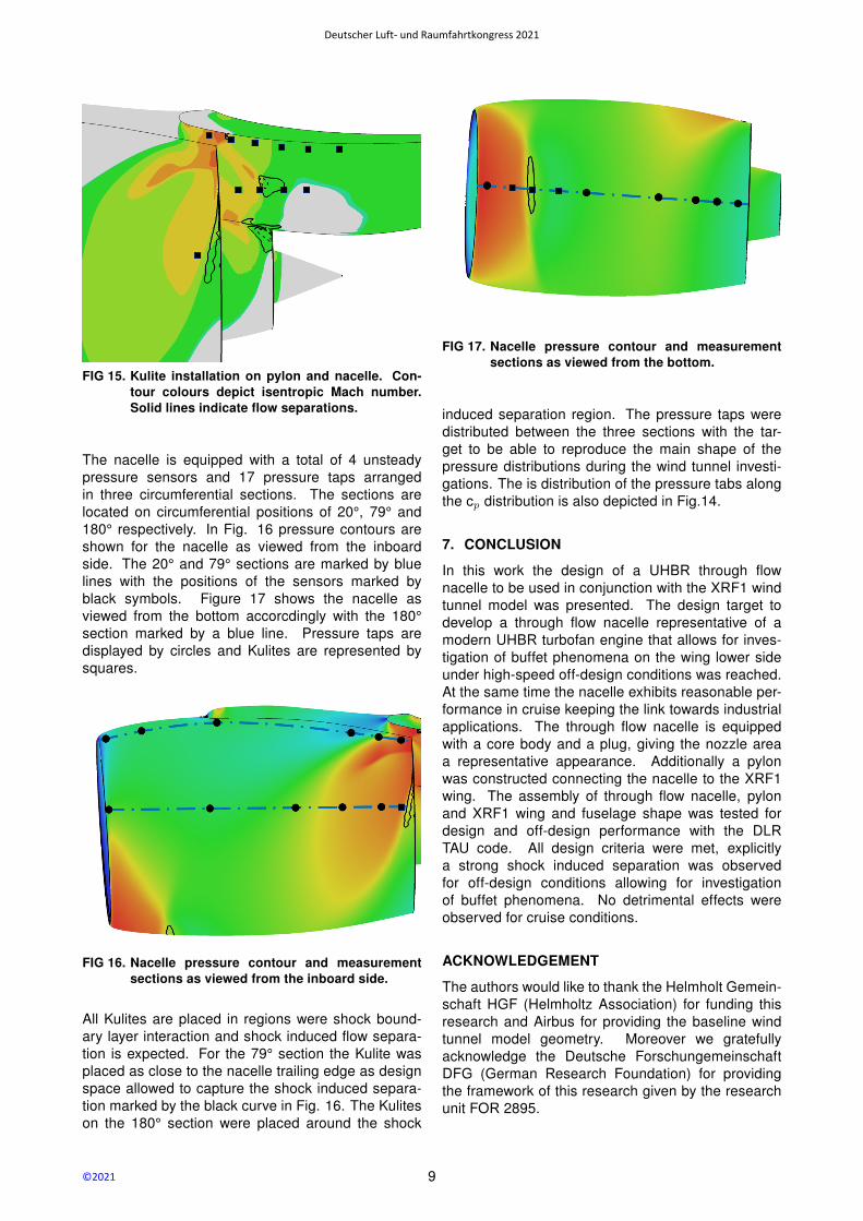
FIG 15. Kulite installation on pylon and nacelle. Con-tour colours depict isentropic Mach number.Solid lines indicate flow separations.
The nacelle is equipped with a total of 4 unsteadypressure sensors and 17 pressure taps arrangedin three circumferential sections. The sections arelocated on circumferential positions of 20°, 79° and180° respectively. In Fig. 16 pressure contours areshown for the nacelle as viewed from the inboardside. The 20° and 79° sections are marked by bluelines with the positions of the sensors marked byblack symbols. Figure 17 shows the nacelle asviewed from the bottom accorcdingly with the 180°section marked by a blue line. Pressure taps aredisplayed by circles and Kulites are represented bysquares.
FIG 16. Nacelle pressure contour and measurementsections as viewed from the inboard side.
All Kulites are placed in regions were shock bound-ary layer interaction and shock induced flow separa-tion is expected. For the 79° section the Kulite wasplaced as close to the nacelle trailing edge as designspace allowed to capture the shock induced separa-tion marked by the black curve in Fig. 16. The Kuliteson the 180° section were placed around the shock
FIG 17. Nacelle pressure contour and measurementsections as viewed from the bottom.
induced separation region. The pressure taps weredistributed between the three sections with the tar-get to be able to reproduce the main shape of thepressure distributions during the wind tunnel investi-gations. The is distribution of the pressure tabs alongthe cp distribution is also depicted in Fig.14.
7. CONCLUSION
In this work the design of a UHBR through flownacelle to be used in conjunction with the XRF1 windtunnel model was presented. The design target todevelop a through flow nacelle representative of amodern UHBR turbofan engine that allows for inves-tigation of buffet phenomena on the wing lower sideunder high-speed off-design conditions was reached.At the same time the nacelle exhibits reasonable per-formance in cruise keeping the link towards industrialapplications. The through flow nacelle is equippedwith a core body and a plug, giving the nozzle areaa representative appearance. Additionally a pylonwas constructed connecting the nacelle to the XRF1wing. The assembly of through flow nacelle, pylonand XRF1 wing and fuselage shape was tested fordesign and off-design performance with the DLRTAU code. All design criteria were met, explicitlya strong shock induced separation was observedfor off-design conditions allowing for investigationof buffet phenomena. No detrimental effects wereobserved for cruise conditions.
ACKNOWLEDGEMENT
The authors would like to thank the Helmholt Gemein-schaft HGF (Helmholtz Association) for funding thisresearch and Airbus for providing the baseline windtunnel model geometry. Moreover we gratefullyacknowledge the Deutsche ForschungemeinschaftDFG (German Research Foundation) for providingthe framework of this research given by the researchunit FOR 2895.
9
Deutscher Luft- und Raumfahrtkongress 2021
©2021

Contact address:
References
[1] D. L. Daggett, S. T. Brown, and R. T. Kawai. Ultra-efficient engine diameter study. Technical ReportCR-2003-212309, NASA, 2003.
[2] H. Hoheisel. Aerodynamic aspects of engine-airframe integration of transport aircraft.Aerospace Science and Technology, (7):475–487, 1997.
[3] R. Rudnik, C.-C. Rossow, and H. Frhr. v. Geyr. Nu-merical simulation of engine/airframe integrationfor high-bypass engines. Aerospace Science andTechnology, 6, 2002.
[4] Thomas Gerhold. Overview of the hybrid ranscode tau. In Norbert Kroll and Jens K. Fassben-der, editors, MEGAFLOW - Numerical Flow Sim-ulation for Aircraft Design, pages 81–92, Berlin,Heidelberg, 2005. Springer Berlin Heidelberg.
[5] S.R. Allmaras, F.T. Johnson, and P.R. Spalart.Modifications and clarifications for the implemen-tation of the spalart-allmaras turbulence model.In 7th Internation Conference on ComputationalFluid Dynamics, Big Island, Hawaii, 2012.
[6] M.L. Shur, M.K. Strelets, A.K. Travin, and P.R.Spalart. Turbulence modeling in rotating andcurved channels: Assessing the spalart-shur cor-rection. AIAA Journal, 38(5):784–702, 2000.
[7] R. Cecora, R.-D. Radespiel, , B. Eisfeld, andA. Probst. Differential reynolds-stress modelingfor aeronautics. AIAA Journal, 53(3):739–755,2015.
[8] A. Magrini, E. Benini, H.-D. Yao, J. Postma, andC. Sheaf. A review of installation effects of ultra-high bypass ratio engines. Progress in AerospaceSciences, (119), 2020.
10
Deutscher Luft- und Raumfahrtkongress 2021
©2021