Design of a steel railroad bridge
184
Transcript of Design of a steel railroad bridge


Illinois Institute
of Technology
UNIVERSITY LIBRARIES

AT 107Cahan, JDesign of a steel railroadbridge
For Use !n LL;:.ry Only


DESIGN OF A
STEEL RAILROAD BRIDGE
A THESIS PRESENTED
BY
.^£&s£&S7,
TO THE
PRESIDENT AND FACULTY
OF
ARMOUR INSTITUTE OF TECHNOLOGY
FOR THE DEGREE OF
BACHELOR OF SCIENCE IN
CIVIL ENGINEERING
HAVING COMPLETED THE PRESCRIBED COURSE
IN CIVIL ENGINEERINGILLINOIS INSTITUTE: OF TECHNOLOGYPAUL V. GALVIN LIBRARY /-// rf35 WEST 33RD STREET JUNE 1, 1908. Ct&prxyutf /CHICAGO, IL 60616


DESIGN OF A STEEL RAILROAD BRIDGE
This structure consists of a single track railroad bridge,
and is designed to span a river, having a width of 600 feet.
The design of this bridge, and the estimate of its cost
may be divided into five parts:
1. Selection of design.
2. Determination of stresses.
3. Calculations of sections and weights.
4. Design of piers and abutments.
5. Cost.
1. SELECTION OF DESIGN
In designing this bridge, one of the first considerations
was regarding the number of spans. This question was decided
by the principle that the total cost of the substructure and
superstructure shall be a minimum. In any event there will
be two land abutments; and the relative cost of piers and
their connecting spans determines the number of piers and
spans which can be most economically built between two abutments.
The cost of bridges is closely proportional to their
weights. If 1 be the length of one span, the formula W= al+bl£
gives a good approximation to the weight, a and b being constants
for the same type of truss. In this, al represents the weight
of the track and floor system, while bl1, represents the weight
of the main trusses and lateral bracing.
If the cost of piers is about equal, and they be spaced at
equal distance apart, the fol^fivring investigation will give

the economical number of spans. Let L* be thetotal distance
between end abutments, x the number of spans, andhence x-1
the number of piers, m the cost of the two abutments, n the
cost of each pier, p the cost per pound of the bridge super-
structure. The weight of x spans, each of length l/x, is
x(aL/x+-bL/xt
), and the total cost of the work is C= m-*-n(x-l)+
p( aL+bli'/x ) where C represents the total cost of the structure.
This will be a minimum when the first derivative of C
with respect to x becomes zero, and this gives N= pbL/x
which shows that the cost of one of the intermediate piers
should equal the cost of the main and lateral trusses of one
of the spans.
Or x= pbli/n gives the economical number of spans.
In order to solve for x, it was necessary to make an
approximate estimate of the cost of one pier and conditions
governing it were as follows.
The height of the high and low water of the river was taken
as 100 and 85 feet above a known bench of elevation. The base
of rail was supposed to be located at a distance of 8 feet above
the high water. The bed of the river consists of fine sand
varying from 5-6 feet in thickness and underlaid by fine gravel
which in its term is supported b/ layers of solid rock, occuring
at an elevation of 70 feet above the referred bench.
In order to avoid driving of piles and, in the meantime,
gives to the piers a solid foundation, the soil beneath the
water will be excavated and the piers built on solid rocK. The
height of the pier was assumed to be 32 feet. The dimensions


-3-
of the pier consists of 9x25 at the bottom and 6x22 at the
top; and the test of stability against sliding and overturning
is determined in the following manner.
Stability against sliding.
Let the coping of the pier be assumed to be 7x23 and its
thickness one foot. The volume and weight of the pier will be
found as follows:
Area of copings 7*2 0+0. 78x7x3= 156.38 square feet.
Volume of " = 156.38x1= 156.38 cubic feet.
Area of the top cross-section= 6xl9+-0.78x6x3«. 127 square feet.
Area of the bottom cross-section=. 9x22+0. 78»9x3= 219.6 "
Volume between the bottom and coping of the pier-
( 127+219.6 )51g 5545 cubic feet.2
Total volume of the pier is therefore 5545+156.38= 5701.38
cubic feet.
The material to be used for construction of piers will
consist of concrete, and assuming the weight of a cubic foot
of concrete to be 150 pounds, the weight of the pier is therefore
150x5701.38^ 855200^ 427.1 tons.
The length of one of the simple spans of the bridge was
assumed to be 150 feet.
The pressure of the wind against the truss and train
together was taken at 30 lbs. per square foot of truss and train.
The pressure of the wind against the truss alone was taken
at 50 lbs. per square foot against twice thevertical projection
of one truss, which for well proportioned trusses will average


about 10 square feet per linear foot of span. The exposed
surface of a train was taken as 10 square feet per linear
foot. The velocity of the stream was taken as 10 feet per
second.
In consideration of the above mentioned items the wind
pressure was computed in the following manner.
The wind surfaces 10x150= 1500 square feet, and thewind,
pressure against the truss is 30x1500-= 45000= 82.5 tons.
The exposed surface of the pier from the low water to
the top of pier is found to he (_24+22)26= 598 square feet.o
The wind pressure against the pier is therefore 20x598-
11960= 5.9 tons.
The crushing strength of ice was assumed to be 15 tons
per square foot, and the thickness of ice one foot. The pier
is about 7 feet wide at the high water, the exposed area
therefore equals, 7x1- 7 square feet, and the pressure pro-
duced on that area was considered to be 15x7= 105 tons.
The formula used in determining the pressure due to
the action of current was P=* svrKvi/2g
(See Baker's Masonry Construction p. 367) where s=- exposed
surface, K= a coefficient taken as 1.1, vfe weight of a
cubic foot of water and v= the velocity of the stream.
In this design "s" was taken as 15x25= 375 square feet;
"w" was assumed to be 62.5 lbs. and "v" as 10 ft/sec.
By substitution of these values the formula becomes
P= 575x62. 5x1. LxlOQs 2010d= 10.5 tons.2x64


The summation of the above mentioned items is found as
follows:
Pressure of wind on the truss 22.5 tons
» » » » » train 22.5 "
» » » » » pier 5.9 "
» ice " M " 105.0 n
w " current 10*5 "
Total force tending to slide- , 166.4 "
The tendency of this force must be resisted by the weight
of the trusses, that of empty cars, and also by the weight
of masonry.
The weight per linear foot of bridge was calculated from
the formula ?/= 650+71, where "1" is the length of the span.
The total weight of 150 foot span is therefore 650x150+-
7x150x150= 255000= 127.5 tons.
The weight of empty cars was assumed to be one half of a
ton per linear foot of span, and the total weight of cars is
0.5x150= 75 tons.
The total weight to resist sliding is therefore found to
be 127.5+-75*427.1-629.6 tons.
Sliding cannot take place, if the coefficient of friction
is equal or greater than 166.4= 0.264 which is within safe629.6
limits in this design.
Test for stability against overturning.
The forces that tend to produce sliding also tend to
cause overturning, the paints of application of these forceswere determined in the following manner.

-6-
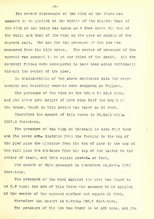
The center ofpressure of the wind on the truss was
assumed tc be applied at the middle of its height; that of
the wind on the train was taken as 8 feet above the top of
the rail; and that of the wind on the pier at middle of the
exposed part. The arm for the pressure of the ice was
measured from the high water. The center of pressure of the
current was assumed tc be at one third of the depth. All the
downward forces were considered to have been acted vertically
through the center of the pier.
In consideration of the above mentioned data the over-
turning and resisting moments were computed as follows.
The pressure of the wind on the truss is 22.5 tons,
and its lever arm- height of pier plus half the depth of
the truss, which in this design was taken as 50 feet.
Therefore the moment of this force is 22. 5x( 32+15 )=
1057.5 foot-tons.
The pressure of the wind on thetrain is also 22.5 tons
and its lever arm= distance from the footing to the top of
the pier plus the distance from the top of pier to the top of
the rail plus the dis tance from the top of the latter to the
center of train, and this equals 32+8-*8— 48 feet.
The moment of this pressure is therefore 22.5x48= 108
foot-tons.
The pressure of the wind against the pier was found to
be 5.9 tons; the arm of this force was assumed to be applied
at the center of the exposed surface and equals 23 feet.
Therefore the moment is 5.9x23= 135.7 foot-tons.
The pressure of the ice was found to be 105 tons, and its


-7-
arm was taken as 15 feet, which in this case is the distance
from the high water.
The moment of this pressure 105x15= 1575 foot-tons.
The pressure of the water is 105 tons , and the depth of
the water was assumed as 21 foot, therefore the arm of this
force is 21/3= 7 feet.
The moment of this pressure is 10.5*7= 7S.5 foot-tons.
The summation of all these moments is therefore
Moment of the wind on the truss 1057.5 foot-tons
" " » " train 1080.0
" » » » » » pier 135.7
B " n pressure of the ice ....1575.0
H " " » » current 75.5
Total overturning moment 3921.7
This overturning moment must be resisted by the moment
produced by the weight of the pier, trusses and that of empty
cars. By taking moments at the toe whose distance is 12.5
feet from the center of the pier, the resisting moment is
therefore equal 629.6x12.5= 7870 foot-tons.
A factor of safety is therefore found to be which equals
7870:3921.7= 2.06, that shows that the piers is Safe enough
for overturning.
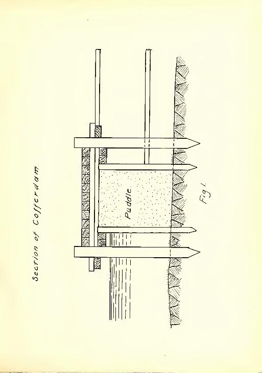
After having found the right dimensions of the pier, it
is also necessary to make an estimate of the cost of a
cofferdam.
The length of the cofferdam was assumed to be 45 feet,
the width of it was taken as 30 feet, while it3 height must be


sufficient to prevent the high water from flowing into the da m.
In this case it is safe enough to assume theheight of the
cofferdam to be 32 feet.
A cross-section of the later is shown on the next page,
Fif. 1.
The description of the construction of the cofferdam
may be outlined in the following manner.
The area to be inclosed is first surrounded by two
rows of ordinary piles. On the outside of the main piles, a
little below the top, are bolted two longitudinal pieces, and
on the inside are fastened two similar pieces, which serve
as guides for the sheet piles, while being driven.
A rod connects the tops of the opposite main piles to
prevent spreading when the puddle is put in. Timber is put
on primarily to carry the fdbtway and so fastened as to
prevent the puddle space from spreading.
In this design the main pi^es were assumed to be spaced
5 feet apart, which will require about 36 piles longitudinally
and 24 ones transversely to the cofferdam. The cost of one
pile including driving was considered to be $3. 20
The sheeting to be used xvas assumed to be 4x8',' and their
cost for 1000 units of B.M. was taken as $25.00
The volume of sheeting required is l/s-r 2( 90x32 )*2( 54x32,! =
3072 cubic feet.
The volume of soil to be excavated was found to be
45x29*|C 726 cubic yards.27
The cost of excavation of a cubic yard of soil 7/as taken
as $1.25.

I
li
_>
X•k
>
^
w>
>


-9-
The cost of laying sheeting was assumed as §5.00 per cubic
yard, while the cost of one cubic yard of concrete was taken
in this design as §5.50 and its laying was considered to cost
about §1.30 per cubic yard of material.
The summation of the cost of the above mentioned
different, items will give the total cost of a pier, which is
found from the following table.
Item Amount
For concrete 209.8 cub. yd.
" laying concrete 209.8 " "
" piles 60 pieces
" sheeting 3G.9 cub. yd.
" laying " 36.9 " "
" excavation 726 cub. yds.
Total cost §3644.50
The number £>f spans can be found next from the formula
x= pbL/n
The value of p in this design was taken as 4 cents per
pound of metal. The total width of the river is 600 feet;
and the value of 1 for pin-connected bridges is usually taken
as .7. Therefore the number of spans required equals
X- 0. 04x7x600x600/3644. 5« 4 or 5.
Prom the last expression it is seen that either four or
five spans ought to give the most economical arrangement of
spans. The cost of the structure under these conditions will
be regarder and a comparison made in order to select the best
design.
Price


-10-
Let the cost of five spans and their piers be considered
first. Since the total length of the bridge is 600 feet, a
length of 120 feet will be assumed for each span. The weigh
of one span was found from the formula W= 6501+71"2" where l is
the length of the span, in this case it is taken as 120 feet.
The total weight of five spans is 5/650x120+7x120x120=
894000 lbs.
If the cost of one pound of metal be taken as 4 cents, the
cost of five spans will be .04x894000= |35760.
When five spans will be selected, there will be only
four abutments, and their cost is 4x3644.5= $14578.
If the selection of the design be considered to be four
spans, the length of each span is therefore 150 ft., and the
total weight of these four spans will be 4(650x150+7x150x150-
1020000 lbs and their cost is therefore .04x1020000=- $40800.
The cost of three piers will be 3x3644. 5» #10933.5.
The total cost of the structure under the second case is
40800+10933.5= $51733.5.
Since the difference between the two cases isnot con-
siderable, a selection of four spans will be of better
practice and therefore it will be adopted.
The selection of the most economical arrangement of panels
and depth of thetruss will be considered next.
Let the weight per foot per truss of the stringers, cross
girders and depth of the track be represented by w, and the
weight per foot per truss of the uniformily distributed load,
equivalent to the live load assumed, w Let the weight per
foot of one main truss be w, and let w„ be the weight per

-11-
p"r foot of lattice, bars, pins, eye bar heads, cover plates,
rivets etc. Then the total load per foot per truss, is w +
W+-W+-W. Let the length of the panel be p then (w^w+w-fW+w, )p
will be the total panel load for one truss. Let N be the
number of panels, d- the depth in feet, and 1- the span in feet,
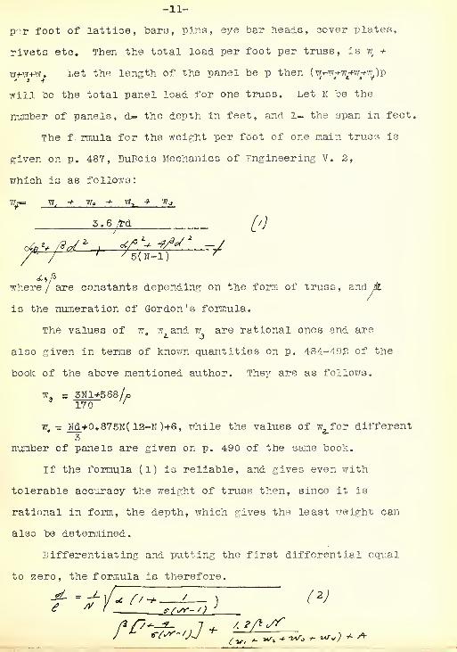
The formula for the weight per foot of one main truss is
given on p. 487, DuBois Mechanics of Engineering V. 2,
which is as follows:
7/,—= W, •* We + W, * Wj
5.6 /rd [/)
/^~~/ f /5CN-1) T
where/ are constants depending on the form of truss, and pL
is the numeration of Gordon's formula.
The values of w. w and w are rational ones and are
also given in terms of known quantities on p. 484-492 of the
book of the above mentioned author. They are as follows.
w, = 3Nl+568/o3
T70~ r
w, - Nd+0.875N( 12-N)+6, while the values of w, for different
number of panels are given on p. 490 of the same book.
If the formula (1) is reliable, and gives even with
tolerable accuracy the weight of truss then, since it is
rational in form, the depth, which gives the least weight can
also be determined.
Differentiating and putting the first differential equal
to zero, the formula is therefore.
+ A


-12-
C ailing the right part of this equation C, the fomula
becomes d= 01.
The values for the above mentioned constants were taken
from Du Bo is Mechanics of Engineering and arranged in talular
form as follows:
H


-13-
Finally, by assuming the number <&'f panels to be 7, the
panel length Is 21.43 feet, the depth is Cl= 0.1346x150-
27.72 feet, andthe total weight per foot of metal is War
2(w^ -* W3
4 w^ *- W-200) = 2(361-f-37^221-f101. 4-200)
= 1040.8 pounds.
From the above computation it is found that 6 panels give
the least weight, and therefore they will be adopted as the
best design. The de; th of the truss is therefore 30.2 feet,
but a depth of 30 feet will be used.
2. DETERMINATION OF STRESSES.
The next proceedure in this design wa3 to analyse the
stresses in the truss of Fif. 2, taking first the stresses due
to dead load. In figuring the stresses for the truss it was
assumed that the dead load was concentrated at the lower panel
points, and the stresses calculated for one half of the truss
only, as the stresses in the other half under the dead load will
be the same. The length of span, center to center of pins
was conlidered to be 150 feet, the depth of the truss between
centers of trusses, was assumed to be 17,feet.
The length of a panel was taken as 25 feet, as it was
found above that six panels will give the best economical
arrangement of panel lengths. The angle which the diaganals
of the truss make with the vertical was therefore found to
be 39 * 40l
The weight per lisear foot of trusses and lateral systems
was found from the formula w«r650*-7 1=^650+^x150-17 00 lbs. that
of the track was 400 lbs., and that of the stringers and floor


-14-
beams was taken a3 600 lbs. making .
The dead panel load per .trus ' 2700x25/2«5375<
A sketch Is therefore
follows.
J- * •
Dead Load
^ hf 1/2X33750* 16875*
in U L.is therefore 16875 Sec 3! * tOs2. *
#The shear in panel tl L~ 3/3x33750-50625*
stress in U, L3is t 15 8ec 30" 40= 72310 1 .
The shear In panel U#Lf 5/2x53750- 84375
The stress in Uf, h, is therefore 8437 ixse .
*l I L
The stress in suspender \J/Lt equal ; the
load oi-* 35750 1 ,
::t passing a sect: 5
\ L, i L Lt 3
the center moment at U, ve//=0-5x33750/2x25- L;
Lx 30.
the stress In L L is 5x53750x25* 70800 lbs.
and this is also equal to the stress in Lt L^
Passing also a section through U,U. U L, and L L,
takin" the center ts at L,"
9


-15-
Ms0s5/3x33750x75-53750x50-33750x25f-UtU, x 30.
Therefore the stress in U U- - 126560 lbs.
Collecting Results.
Stress in \JZ L^= +21940 lbs.
" » U 2h3
= -16875 lbs.
n " U, L 3 r +72310 lbs.
" " U, L tr -33750 lbs.
" U, L,= -109690 lbs.
tt U, U^- -112500 lbs.
" U 2 Ux- -126550 lbs.
" L, L 2- +70300 lbs.
n L3
L y- -1-112500 lbs.
Live Load Stresses.
In designing this bridge the live load was considered as
consisted of2 -177.5 ton engines, followed by 5000 lbs. per
foot of track. The maximum shears and bending moments were
computed in all thepanels, and the stresses in every member
were therefore determined.
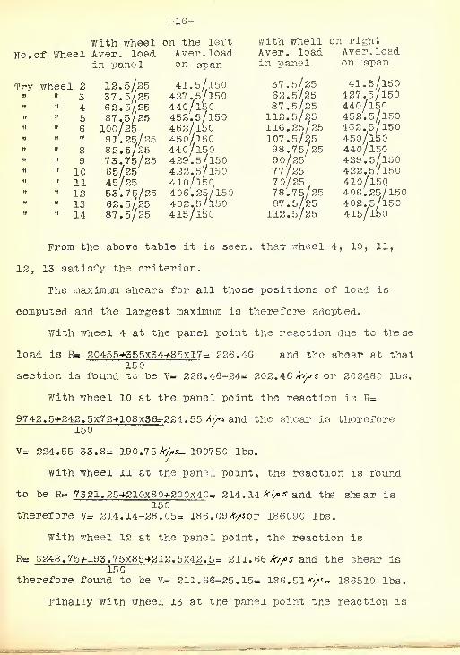
Determination of maximum shear in 1 panel. The maximum
shear in any panel occurs when the average load in the panel
is equal to the average load span the entire span.
The wheel loads were therefore placed at the paai panel
point and tested for the criterion in the following manner.

-16-
With wheel on the left
No. of Wheel Aver, load Aver. loadin panel on span
12.5/25 41.5/15037.5/25 427.5/15062.5/25 440/15087.5/25 452.5/150100/25 462/15091.25/25 450/15082.5/25 440/l5073.75/25 429.5/15065/25 422.5/15045/25 410/15053.75/25 406. 25/15062.5/25 402.5/15087.5/25 415/150
With whell on rightAver, load Aver. loadin panel on span
Try


-17-
Rg 5257. 5-^177. 5x90-^225x45= 209.05 Ay* and the shear due to150
these loads V= 209.05-24= 185.05A/*or 185050 lbs.
From the above figurws it is seen that wheel 4 produces
the maximum shear in the first panel, and its amount is found
to be equal to 202460 lbs.
Determination of maximum shear in 2nd panel.
In order to find the maximum shear in this panel it is
necessary to place the wheel at the panel point and test
them for the criterion in the following manner.
With whell on left With wheel on rightNo. of wheel Aver, load Aver. load Aver. load Aver. load
in panel on span in panel on span
12.5/25 355/150 37.5/25 350/l5037.5/25 365/150 62.5/25 365/l5062.5/25 377.5/150 87.5/25 377.5/15087.5/25 390/150 112.5/25 39o/l50100/25 412.5/150 116. 25/25 412.5/15091.25/25 425/150 107.5/25 412.5/l5082.5/25 440/l50 98.75/50 440/l5073.75/25 452.5/15O 30/50 452.5/15065/25 460/150 77.5/25 46o/l5045/25 430/150 70/25 420/15053/25 417.5/150 78/25 417.5/l5062.5/25 405/150 87.5/25 405/150
From the above table it was found that wheel 4, 9,
10, 12 satisfy the criterion. By comparing their shears the
largest one will be selected.
Fith wheel 4 at thepanel point the reaction is found to
be R= 20455*-5S5x9+22. 5x4.
5
- 158.35V 3" and the shear is150
therefore V= 158.35-24= 134.35A-/J"or 134350 lbs.
With wheel 9 at the panel point the reaction is R=
20455^-555x39-^97.5x19.5=: 241.34 /Wandthe shear du<=> to these loads150
Try


-16-
V= 241.34-37,5-45.8= 108,04 /r^s
With wheel 10 at the panel point the reaction is found
to he R= 19092. 5y-542. 5x47f-117. 5x25. 5= 253 *'/> s and the shear150
is therefore V- 253-100-41.6= 111.4/^Jor 111400 lbs.
Finally with wheel 12 at thepanel point thereaction
is found to he Rg 11893. 5*367. 5x60-»150x50- 316.38 Av> s
150and the reaction is therefore v= 316.28-73.75-25.15- 119.38 /b/>s.
From theabove it is seen that wheel 4 produces the
maximum shear in the second panel and its amount is equivalent
to 134350 lbs.
Determination of maximum shear in 3rd panel.
The method of proceedure of finding the maximum shear
in this panel is obtained in the same way, as in the previous
cases, by placing the wheel load at the panel points in the
following manner.
With wheel on left of With wheel on right ofNo. of wheel panel point panel point
Aver. load Avar. load Aver. load Aver. loadin panel on span in panel on span
12.5/25 290/150 37.5/25 290/15037.5/25 306. 25/150 62.5/25 306. 25/15062.5/25 322.5/150 87.5/25 322.5/15087.5/25 322.5/150 112.5/25 522.5/150100/25 355/150 116. 25/25 355/l5391.25/25 362/150 108.5/25 362/l5082.25/25 377/150 98.75/25 377/15073.75/25 339.5/150 90/25 389.5/15065/25 410/150 77.5/25 410/l5045/25 430/150 70/25 430/15053.75/35 442.5/150 98.75/25 442.5/15062.5/25 455/150 87.5/25 455/150
From the above figures it was found that T7heel 3, 10, 12,
13 satisfy the criterion.
With wheel 3 at the panel point thereaction is R=
Try


-19-
n= 13520/150= 90.13A/>*or 90130 IDs. and therefore the shear
is equal V= 90,13-11.5- 78.63A/>*or, 78630 lbs.
With wheel 10 at the panel point the reaction is found
to he R=r 20455*355x22-1-55x11= 192.46 A^^and the shear is150
V= 192.46-112.5-41.6-= 38. 36 /r</>s.
With wheel 12 at the panel point the reaction is
R- 20455-^555x55^87.5x17.5= 239.4 */»s andthe shear is therefore150
V= 229.4-161.25-25.11- 43.04 *>/>*.
With wheel 13 at the panel point the reaction is found
to be R= 20455->-355x40-tlQOx20r=. 244.36Av/..s and the shear due150
to these loads is V=- 244.36-117.5-24^ 42.86/ry>«.
By comparing the above values it is found that wheel 3
produces themaximum shear in this panel and its value is
equal to 78630 lbs.
Determination of maximum shear in 4th panel
.
In a similar manner it was found that wheel 2 produces
a maximum shear in this panel. Thereaction is th erefore
R= 5790*190x2= 41. 13 A/'/as, and the shear is found to be V=150
41.13-4= 37.15Ay°'or 37130 lbs.
It was also found that wheel 2 produces a maximum shear
in 5th panel. The reaction is R= 2050*128.75x1= 14.52 A~//° s .
150and the shear is therefore V= 14. 52-4-10. 52^v :°^or 10520 lbs.
Determination of maximum bending moment in 1st panel,
The maximum moment in any panel occurs when the average
load upon the span is equal or just great than the average
load in front of the panel point.


-30-
The wheel loads were placed at the panel point and
tested for the criterion in the following manner.
With wheel load on wlth whee* load ™No. of wheel left of panel point right of panel point
Aver. load Aver. load Aver. load Aver. load
in front of on the in front on the span
panel span of panel
Try wheel 2 18.5/25 415/150 37.5/25 W^°" 3 37.5/25 427.5/150 62.5/25 427.5/150
4 62.5/25 440/150 87.5/25 440/15» 5 87.5/25 452.5/150 112.5/25 452.5/150
" " 6 100/25 462.5/150 116. 25/25 462. 5/.150" " 7 91.25/25 450/150 107.5/25 453/150" " 8 82.5/25 440/150 98.75/25 440/l50" " 9 73.75/25 429.5/150 90/25 429.5/150" " 10 65/25 427.5/150 77/25 422.5/150" " 11 45/25 410/l50 70/25 410/l50
" 12 53.75/25 406. 25/150 78.75/25 406. 25/150" 13 62.5/25 402.5/150 87.5/25 402.5/l50
" " 14 87.5/25 415/150 112.5/25 415/150
From the above table it was found that wheel 4, 10, 11
12, 13 satisfy the criterion.
With wheel 4 at the panel point thereaction due to
these loads is R= 20455^-355x34485x17= 226.46 and the maximum150
bending moment is therefore 11=226.46x25-600= 5061500 ft lbs.
With wheel 10 athe panel point the reaction is R»
9742. 5^242. 5x7 2-f180x36= 224.55 /r//>s and the maximum bending150 7
moment is therefore M-= 224.55x25-845= 4768750 ft lbs.
With wheel 12 at the panel point the reaction is
R= 7321. 25-^210x80-^200x40- 214.14. The maximum bending150
moment is therefore \L-= 214.14x25- 701.25= 465252? ft lbs.
With wheel 12 at the panel point the reaction is R=.
6248.
7
5*195. 75x35+212. 5x42.
5
-= 211.66 /(v>*.150 /


-21-
The maximum bending moment is there M= 211. 66x25-628. 75=
4662750 ft-lbs.
Finally with wheel 13 at the panel point the reaction
was found to be R= 5257. 5*177. 5x90*-22. 5x45= 209. 05 >'/> s
150The maximum bending moment is therefore M= 209.05x25-
600= 4626250 ft lbs.
From the above mentioned it is seen that wheel 4 produces
the largest bending moment and its amount equals 5061500 foot-
lbs.
Determination of maximum bending moment in2nd panel.
In this case the wheel load are also placed at the panel
point and tested for the criterion in the following manner.
Try wheel 2 12.5/50 355/l50 37.5/50 355/l50" " 3 37.5/5O 365/150 62.5/50 365/150" " 4 62.5/50 377.5/15O 87.5/50 377.5/l50" " 5 87.5/50 390/150 112.5/50 390/150" " 6 112.5/50 412.5/150 128.75/50 412.5/l50
7 128.75/50 425/150 145/50 425/l50» 11 127.5/50 430/150 152.5/50 430/l50$ 12 127.5/50 417,5/150 152.5/50 417.5/l50" 13 127.5/50 405/150 152.5/50 405/150
From the table it is seen that wheel 7, 11, 12 and 13
satisfy the criterion.
With wheel 7 at the panel point the reaction is R=
20455+355x28*7 0x14=. 209.16 kips, and the maximum bending moment150
is therefore M= 208.16x50-2683.75=7874250 ft-lbs.
With wheel ll at the panel point, the reaction is found
t0 be R- 14167 . 5-^292. 5x55tl37 .50x27 .
5
= 226.9 A,/>s150 7
The maximum bending moment is therefore M= 226.9x50-3835-
7510000 ft- lbs.

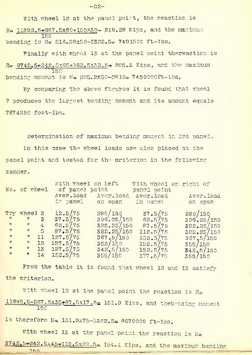
with wheel 12 at the panel point, the reaction is
r= 11892, 5+367. 5x60+150x50 =. 216.38 Kips, and the maximum150
bending is U- 216.38x50-3322.5= 7491500 ft- lbs.
Finally with wheel 13 at the panel point thereaction is
R= 9742,5+242.5x65+163.5x3 2.5= 205.3 Kips, and the maximum150
bending moment is M= 305.3x50-3810= 7450000ft-lbs.
By comparing the above figures it is found that wheel
7 produces the largest bending moment and its amount equals
7874350 foot-lbs.
Determination of maximum bending moment in 3rd panel.
In this case the wheel loads are also placed at the
panel point and tested for th^ criterion in the following
manner.
With wheel on left With wheel on right ofNo. of wheel of panel point panel point
Aver. load Aver. load Aver. load Aver. loadin panel on span in panel on span
Try wheel 3 12.5/75 290/l50 37.5/75 29o/l50" " 3 37.5/75 306.25/150 62.5/75 306.25/l50" 4 62.5/75 333.25/150 87.5/75 322. 25'/150
5 87.5/75 322.25/150 112.5/75 322.25/l50" 11 127.5/75 367.5/150 152.5/75 367.5/l50
" " 12 127.5/75 355/150 152.5/75 355/150» 13 127.5/75 342.5/150 152.5/75 342.5/150" 14 152.5/75 355/150 177.5/75 355/150
From the table it is found that wheel 12 and 13 satisfy
the criterion.
With wheel 12 at the panel point the reaction is R=
11892. 5+267 . 5x35+87 . 5x17
.
5= 151.9 Kips, and theb-nding moment150
is therefore M= 151.9x75-3322.5= 8070000 ft-lbs.
With wheel 13 at the panel point the reaction is R=
.5743.5+343. 5x45+113.5x32.5= 154.1 Kips, and the maximum bending


-23-
moment is therefore M= 154.1x75-3572.5= 798500 ft-lbs.
By comparing the last figures it is found that wheel
12 produces the largest bending moment and its amount equals
8070000 foot-lbs.
After finding the shears and bending moment in all the
panel, the stresses in web numbers and also in the chords
are obtained in the following manner.
The stress in u, Lf 2024S0 Sec 39*4oi 253200*
U, Lt 78630 Sec 39 40= 1022002- t
» " " U 1- 78630*2. 3
H " UaL» 37130*
" " " U/Uf 7874250/30= 26247
5'
" " U, Uf 8070000/30^ 269000*
" H L Iif 5061500/30- 1687201
» » L,Ii= 7874250/30= 262475*^
The stress in the counter brace U,L«-is found by con-
sidering the live and dead load shear in the panel u, L._
The live load shear in this panel is 37130, which evidently
causes compression in U^L. But the dead load shear in this
panel is- 16875 that produces tension in the above member.
The resultant is 20255 which is the vertical component of U, L^
causing compression in U^L.and therefore a counter brace is
r
needed.
The stress in U, L^is therefore 20255 Sec 39°40-= 26330.
With regard to a counter stress in panel uy L tfthe dead


-24-
and live shears were also considered.
The live load is -* 10520, producing compression in U^L,
but the dead load shear is - 55625, causing tension in the
above member. The resultant is - 45105, producing tension
in the diaganal U^L and therefore no counter brace is needed
in panel \J ¥ I>.
Determination of maximum shear and bending momentin a 25-0 stringer.
The maximum shear in a stringer occurs at the point of
supports.
The wheel loads were placed at the end and the she ars
found in the following manner.
Witji wheel 1 at the end the reaction is found to be
Rs 1057. 5+113. 5x2= 50.5 Kips or 50500 lbs.25
With wheel 2 at the end the reaction is R= 1650+115.25x1=1
2570.65 Kips- 70650 lbs.
With wheel 3 at the end the reaction is therefore R=
1506.25+107.5X1- 64.5 Kips=. 64500 lbs.25
Placing wheel 4 at the end the reaction is found to
be Rs 1401.25/25- 56.05 Kips- 56050 lbs.
Finally with wheel 5 at the end thereaction is R=
1145/25=^ 45.8 Kips=. 45800 lbs.
The maximum shear therefore occurs under wheel 2 and
its amount is 7 0650 lbs.
The condition for determining the maximum bending moment
in a stringer is the same so that for a simple beam. The
criterion is, that the wheel producing the maximum bending


-25-
raoment must be so far from the end, as the center of gravity
of all the wheels is from the other end. For this purpose
the wheel Is placed at the center of the stringer and tested
for the criterion in the following manner.
With,wheel on left With wheel on rightNo. of wheel of panel point of panel point
Aver. load Aver. load Aver, load Aver. loadin panel on span in panel on span
Try wheel 2 12.5/l2.5 87.5/25 37.5/l2.5 87.5/25» » 3 25/l25 100/25 50/l2.5 100/25» "4 50/l2.5 100/25 75/12.5 100/25" " 5 50/l2.5 91.25/25 75/12.5 91.25/25
From theabove table it is found that wheel 3 and 4 satisfy
the criterion.
With wheel 3 at the center, the reaction is found to be
R= 750-*-100x3.5= 44 Kips=r 44000 lbs., and the maximum bending25
moment is M= 44000x11.25-12500= 370000 ft-lbs.
With wheel 4 at the center the reaction is R=
750-f100x6.
2
5= 55 Kips«= 55000 lbs.
25
The maximum bending moment is therefore M= 55000x13.75-37500= 381250 ft-lbs.
From the last expression it is seen that wheel 4 produces
the largest bending moment and its moment is 381250 foot-lbs.
Determination of maximum floor beam concentration.
The criterion for maximum floor beam reaction is that
the average load in the panel on the left must be equal to or
just greater than the average panel load upon the right includ-
ing the wheel at the panel point. The wheel loads are placed
at the panel point and tested for the criterion in the
following manner.


-26-
With wheel on left With wheel on rightNo. of wheel of panel point of panel ppint
Aver. load Aver. load Aver. load Av^r.loadon left on span on left on span
Try wheeel 2 12.5/25 116. 25/25 37.5/25 91.25/25" 3 37.5/25 107.5/25 62.5/25 82.5/25" 4 62.5/25 98.75/25 87.5/25 73.75/25
» n 5 37.5/25 90/25 112.5/25 65/25
From above figures it is found that wheel 4 and 5 pro-
duces the maximum floor beam reaction.
With wheel 5 at the center the maximum floor beam reaction
is found to be R-IMR- 114. 5/25+975-Z-87. 5x2-91 . 8 Kips= 91800 lbs.'
*25
With wheel 4 at the center the reaction is R=R#
-*R*1401.25
-525-*-62. 5x7/25= 94.55 Klps» 94550 lbs.
Therefore wheel 4 produces the maximum floor beam
reaction and its amount is 94550 lbs.
25
Determination of stress in the top lateral bracing.
These laterals will be proportioned to resist a lateral
force of 20 pounds for each linear foot of the span, thus
making the panel load equal to 200x25= 5000 pounds. A sketch
of the laterals is shown below and with the above loading
the stresses are determined as follows.
0* cs.-
The angle that the diaganals make with the vertical
is 55° 50'.


-27-
The stress in U2 U» 5000/2 Sec 55°50= 4500 pounds.
» U, U- 5/2x5000 Sec' 55' 50- 13500 "
" " " U, Uf 2500 pounds.
" " " U U- 7500 "
•Che bottom lateral bracing is proportioned to resist a
lateral force of 600 pounds for each foot of the span; 450
pounds of this to be treated as a moving load, and as acting
on a train of cars, at a line of 6 feet above base of rail.
A sketch is also given below and the stresses determined
as follows:
L. /., Zj Z^ J-'r Z.,'
Fixed load stresses.
In this case the fixed load stresses will be determined
first. The fixed panel load is 150x25= 3750 pounds. With
this loading the stresses are figured in the fallowing manner,
The stress in L, L= 5/2x3750= 9375 pounds.
" " L, L= 9375x1.78= 16800 »
" " L L- 3/2x3750= 5620 "
» » » L L- 5620x1.78= 9960 "
" " " h LT 3750/2= 1875 »
" " " L L» 1875x1.78= 3380 »•» ¥
" " " L,L= 3750x150x150= 24880 rounds
.
,
* 8x17" " " L L= AX3750X25=-2206Q »
* 317


-28-
The stress in L L- 5x5750x25s - 13760 pounds.*" 2x17
\*7 +
L. L- -h
22060
13760
Live load stresses.
The live load panel load is 450x25= 11250 pounds.
The shear in panel L Lj 11250 pounds.
The stress in L L= 11250x1.78= 19980 pounds.
The shear in panel L L= 10/6x11250= 187 60 »
The stress in hz
L., 18760x1.78= 3320G "
The shear in panel L, L- 15/6x11250= 28120 "
The stress in L L= 28120x1.78- 49760
Determination of streoses in the Portal Bracing.
A sketch and dimensions of the Portal Bracing is given
below and the stress are determined in the following manner.


-29-
The bracing was design to resist a lateral force of 150
pounds per. linear foot of spans. The wind load per panel is
therefore 150x25= 3750 pounds. The force applied at the top
of the portal is 2x3750= 7500 pounds. With this loading
and also with imaginary forces that are put in for convenient
coputation the stresses are figured as follows.
The reaction is found by talcing moments about the
base of the Portal, and R= 7500x50.07= 17200 pounds.17
Let the shear be divided equally between the two
diagonals cut by any section parallel to the end post. The
stress in each diagonal is 8600x1.41= 12040 pounds. The
imaginary force at joint (2) is 12040 cos 4730= - 8120 pounds.
Taking moments about joint (3), the imaginary force at
(1) is found to be M=0=Pxll+8120v-3750x29.85, and Ps-13920
pounds. Also talcing moments about joint (2), the horizontal
force at (3), is found to be M*r0=Px5+-5750x34. 8-13920x8
Ps 9550 pounds.
Talcing out joint (3) by itself and solving horizontallyO I
we have, zy= 0»3550+FMC03 4220; FM-13370 pounds also solving
vertically it becomes £ >= ".- AFf13370^-4220-17200, hence
AF= 8240 pounds.
Talcing out joint (3) by itself and solving horizontally,
we have £^„ o*AH+12040•&« 4730- 8240 hence AH=~670 pounds.
By talcing out joint ( 1 ) by itself and solving also
vertically, we get I y= o= AH-HT£*4-730. Therefore HT=-*900 lbs.
By solving it horizontally, we have, <? = DT ->-9 00 6*47 30+21420
Hence DT=r-22025 pounds.
Passing a section through SQ, QS, SM andtaking moments


-50-
about joint (7), we have, M=rO=DQx6-1204 x6 S/>/45*-21420x6+-
9550x5+-3750x34. 8-1.7200x5. 5.
Therefore DQ»-26930 pounds.
Next talcing out joint (10) by itself and solving hor-
izontally, we have, Zx =r <?--DQ-*-DU-12040C>e7J45-12040 £»s45°
Hence D N-+22386 pounds.
Talcing also joint 4 by itself and solving horizontally,
we have zx= 0=~DN-NLCV»j4730
Therefore NL—31540 pounds.
Next taking out joint 5 by itself and solving horizontally,
we have£x=0—LK*12040&s4730.
Hence LK=-+16856 pounds.
Finally, talcing out joint (8) by itself and solving
horizontally, we have,rx»*«-MS+12040G>»45+LK*MK#»4750 - 8120.
Hence MS=+4150 pounds, arid solving it vertically, we
getZ/= 0= 12040&tf45-31340Oa4730+MK&*4230.
Therefore MK--+16760 pounds.
3. Calculations of sections and Weights.
Design of floor timbers.
The greatest stress in the cross-tie is produced by the
loading of 25000 pounds placed on one axle. If the cross-
ties be 8 inches wide and spaced 6 inches in the clear, three
ties and spaces will cover a length of 3 1/2 feet. Assuming
the total weight of the track as 450 pounds per linear foot,
the weight for a length of 3 1/2 feet is 1575 pounds, and for
each rail on each tie 8600 pounds. The dead load is relatively
so small that it may be assumed to be also concentrated at the


-31-
track rails, without appreciable error. The steingers are
spaced 6 1/2 feet apart. The cross-tie is a beam with two con-
centrated loads, each of 8600 pounds, spaced 4 feet 11 1/2
inches apart and placed symmetrically with respect to the
supports furnished by the stringers. The bending moment is
therefore 8600x9.25= 79550 inch-pounds. For a unit stress of
1000 pounds per square inch and a width of 8 inches, the re-
quired depth of the cross-tie is found to be 8 inches. The
bearing value of timber is taken as 250 pounds per square
inch. The bearing area required is then 8600/250=34 square
inches and if the width of thebase of the rail be 6 inches
the breadth must be 7 inches which is safe enough within the
value assumed.
Design of Track Stringers.
Thd span of the stringer equals the panel length of the
truss, or 25 feet. Let the weight of the track carried by one
stringer be assumed to be 5000 pounds, making the dead load
10500 pounds.
The maximum shear for a stringer of 25 feet was found
to be 70650 pounds, while the dead load shear is 5250 pounds,
making the total shear 75900 pounds.
Let thedepth of the stringer be taken as 36 inches.
A thickness of 7/l6 allows for enough rivets to be deducted
from the web. Put this thickness, however, required stiffeners
to be used, which may be avoided by increasing the thickness
to 1/2.
The dead load bending moment is 10500x25= 33100 ft-lbs.
,
8


-52-
while the live load bending moment was found to be 381250
ft-lbs., thus maKing thetotal moment 381250+33100=- 414350
foot-pounds.
Assuming the unit tensile stress as 10000 pounds, and
the effective depth to be 32.5 inches, one half of flange is
therefore A=414550xl2= 15.3 square inches.32.5x10000
Ldt 2L-Sx6J5/4 be assumed, thenet area is A» 2(8.44-
.75)=- 15.38 square inches.
The actual effective depth is 32.44 inches, and the
revised flange area is A= 414350x 12= 15.32 square inches,32.44x10000
and therefore these angles will be used.
Let the rivet pitch in the flange be determined next.
The maximum vertical shear at the end is 75900 pounds, and
the increment of flange stress per linear inch is 15.32 x15.38
75900=: 2340 pounds.32.44
The vertical load on the flange is 25600/42= 595 pounds.
The resultant of these horizontal and vertical componentsjL
is /f* /2340 + 59^" 2410 pounds.
The allowable bearing value of 7/8 rivet in 1/2 web
plate is 8/l0x7/8xl/2x1500= 5280 pounds, and hence the
theoretic rivet pitch at the end is 5280/2410= 2.3 inches.
Since the vertical angles which connect the end of the
stringer to theweb of the floor beam are to be straight,
fillers whose thickness equals that of the flange angles are
placed. The value of 7/8 rivet in single shear at 7200
pounds per square inch is 4320 pounds.
The number of rivets required to transmit the shear


-53-
from the web of the stringer to the connection angles is 75900/
5250= 15.
The rivets connecting the other legs of these angles to
the web of the floor beam are field rivets, and since they
are in single shear thenumber required is 75900/4320= 18
shop rivets or 28 field rivets.
The estimate of the weight of one stringer is as follows:
4 flange angles 6x6x3/4x24-11 '<© 28.7^ 287 0^
1 web plate 36xl/2x24-ll" (a) 61.2* 1550*
4 connection angles 6x6x1/2x5-4" 3/8 19.6- 274.4
4 fillers 9xl/2x2-0" (S 15.3*= 122.
4
#
250 pairs of rivet heads 0.369= 88.0
Total . 4834.8**
a quantity nearly equal to the value assumed.
Design of Floor Beams.
For convenience in erection, bracket angles are riveted
to the lower flange of the floor beam or to the web just
above the flange, on which to support the stringers until
their end connecting angles are riveted to the floor-beam
webs.
Assuming that the vertical legs of the flange angles
do not exceed 4 inches, it is found that a depth of 48 inches
will bring the top of the eross-ties about 3 inches higher
than the top of the floor beam.
The floor beam carries, in addition to its own weight,
two concentrated loads 3-3 from its center, each load con-
sisting of the maximum sum of the adjacent reactions of the


-34-
stringers on both sides. This sum includes the weight of
one stringer, and of the track which it supports, and the
corresponding live load. The maximum floor beam reaction
was found to be 94550 pounds, and assuming the weight of the
floor beam to be 5000 poundj^ the total maximum shear is
therefore 94550*10500+2500= 107550 pounds, where 10500
is the <5ead load reaction of one stringer.
The allowable unit stress is 8/10x9000- 7200, and the
required net area of the web is 107550/7200= 14.93 square
inches.if
Let the thickness of the web be taken as 7/lS, then the
gross area is 48x7/l6=r 20.66 square inches, which allows
enough rivets to be deducted from the ^eb £a?esfl for the splice
section. The length of the floor beam is 17 feet, and the
dead load bending moment is//- =5000x17 = 10625 foot-lbs.8
The live load bending moment was found to be 551512.5 foot-
lbs., making the total bending moment 562137.5 foot-lbs.
Assuming the effective depth to be 46 inches, the area
of one half of the flange is As 562157.5x12- 14.61 square inches,10000x46
Let the following composition of the flange be taken,
which furnishes a net area of 14.74 square inches. 2 angles
5x4x9/l6, 2(4.75-1.10)= 7.24 square inches.
1 cover plate, 12x3/4, 9-3.5- 7.50
Total net area 14.74 square inches.
The center of gravity of the solid section of the upper
flange is 7.24x1.48= 0.73 inches, below the backs of the14.74
angles, and that of the net section of the lower fiance is


-35-
9.5x1.48/18.5:= 0.77 inches above the backs of the angles.
The effective depth is therefore 48=1.5= 46.5 inches, and
the revised flange area is A= 674 5850= 14.59 square inches.10000X46.5
The above mentioned angles a plate mill therefore be used.
Let the rivet pitch of the flange angles be considered
next.
The bearing value of 7/8 rivet in 7/l6 web plate is
8/l0x7/8x7/l6xl5000= 462oT
The increment of flange stress per linear inch is
14.59x107550= 2100^ and the pitch is 462o/2100~ 2.45 inches.14.74 ' 4659
In the space between the stringers the pitch is made 6
inches, the maximum allo?;ed.
In figuring the number of rivets in the web splice the
bearing value of rivets will be considered, since their
value is less than that in double shear. The bearing value
of 7/8 rivet in a 7/l6 web plate is 8/l0x7/8x7/l0xl5000=. 4520^
The number of rivets is therefore 107550/4620= 24
( shop rivets).
Since the rivets are field ones, their number will be
increased by 5ofo and is therefore 1.5x24= 36.
The estimate of the weight of one floor beam is as follovrs:
2 flange angles, 5x5x3/l6xl6-l" r& 16. st 523 pounds2 flange angles, 5x4x3/6x14x4 » 16. 2". 4641 cover plate, 12x3/4x16- 1', .30.6* 49 w
1 cover plate, 12x3/4x11-4^ » 3 0.6* 350 "
1 web plate, 48x7/l6xll-l 1/2 * 71.44". 785 "
2 web plates, 23x7/16x7-5 1/2 » 34.24T 250 "
4 splice Plates, 30x3/16x3-8* - 57. 4f 175 »
4 filler plates, 27xl/2x2-10" , *45.9t 95 »
4 connection angles, 3 l/2x 3 1 /2x 1/2x2-4" 11. it 25 "


-36-
4 oonnection angles, 3 1/3x3 l/2x 1/2x2-11/6) 11.5 22 pounds4 filler plates, 7x3/16x2-11* „ * 13. 4?.... 23 •»
4 angles, 4X3 1/2x3/8x2-7 l/2'
» 3.1* ....20 »
4 filler plates, 3 1/2x3/16x2-1 6.7? 15 "
4 filler plates, 3 l/2xl/2x2-4" * 6.7* 15 "
4 angles, 3 l/2x3 l/2x 3/8x3-3" * 8. 5.... Ill "
4 bracket angles, 5x4x3/8x1^3* * 85 *'.... 55 tt
600 airs of rivet heads * 0.369*. 225 "
Total 4647 "
Se-ctions of Intermediate Posts.
Let be required to design the section of the post U2L 3
Neglecting the wind stresses, which are relatively too small
to affect, the total stress to be considered is 78630+16875/2=
87060. Let 2-12 inch- 35 channels be tried. The radius cf
gyration is 4.17 and the allowable unit stress is P= 8500-
. 45x30x12=- 4620 pounds.4.17
The required area is 87060/4620= 18.86 square inches.
The area of the two channels is 2x10.29= 20.58 square inches,
and therefore they will be used. The distance bacK to back of
channels, in order to make the radii of gyration equal is 9.59.
In a similar manner it is found that two 12- inch 20.5
pounds channels are needed for the post U L. the radius of
gyration being 4.61 inches, the allowable unit compressive
stress per square inch in P= 8500- 45x30x12= 3260?4.61
The required sectional area is 37130/3260= 11.4 square
inches. The area of the two channesl is 2x6.03= 12.06 sq.
inches and therefore they will be used. The distance back to
back of channels is found to be 10.48 inches.
Sections of Diagonals and Suspender.


-37-
Since the stress in U, L3 is a tension of 210800 pounds,
it may be)compose& of one pair of eye-bars. The wind stress
may he neglected in designing the member according to the
specifications. For the unit tensile stress of lOOOtfpounds
per square inch, the sectional area must be 21080o/lOOOO=
21.08 square inches. Two eye-bars, 8x1 3/8, provide an area
of 22 square inches, and therefore they will be used.
The stress in U^L^was found to be 113170 pounds, and for
a unit tensile stress of 10000 pounds per square inch the
required sectional area is 113170/l0000= 11.315 square
inches.
Two eye-bars, 6x1, provide an area of 12 square inches
and therefore they will be used.
In a similar manner the counter brace is designed. The
stress in II hsis a tension of 26330 pounds. The required
area is 26330/10000^2.63 square inches. Therefore one eye-
bar, 4x3/4, which provides a sectional area of 3 square inches
will be used.
The suspender, U, L, will be designed as a stiff member.
It required net sectional area is 111320/8000= 14.92 square
inches. Two 12- inch 35 pound channels will be selected,
as they will furnish 15.5 square inches, after deducting two
rivet holes in both the web and flanges of each channel.
Lower Chord Sections.
Since the wind stresses in these chords are less than
30 percent of the maximum strains due to the dead and live
loads, they can be therefore neglected.


The equivalent live load is L, L z is 203870 pounds.
With a unit stress of 10000 pounds per square inch the re-
quired area is 20387 0/l0000= 20.39 square inches. Let
L L^be "composed of two web plates and f ur angles, since the
eye-bar heads of the 8 inch eye-bars are 17 inches deep , let
the web plates be made 18 inches deep so as to avoid cutting:
the angles in order to pass the eye-bar heads at L. Selecting
2 web plates 18x1/2 and 4 angles 3 1/2x3 l/2x 5/8, the rivets
in the end pin plates can be so arranged as not to deduct
more than 3 rivet holes in each web plate and oi e in each-
angle, giving a net area of 20.46 square inches.
The area of 2 web plates, 18xl/2 is 18 square inches,
while the area of 4 angles, 3 l/2x3 1/2x5/8 is 7.96 square
inches, making the total gross area 25.96 square inches. The
area of 4 rivet holes in the angles is 4x5/8- 2.5 square inches,
while the area of 6 rivet holes in the webs is 6xl/2« 3 square
inches. The net area is therefore 2$ . 9.6-2 . 5-3- 20.46 square
inches, and therefore this section will be used.
The member LjL^will consist of eye-bars. The stress in
this member is 318725 pounds, and wiil with an allowable unit
stress of 10000 pounds per square inch, the required net area
is 318725/100 0=: 31.87 square inches. Let 4 eye-bars, 8x1^ be
selected. The area of these eye-bars is 4x8x1= 32 square
inches, and therefore they will be used.
Upper Chord Sections.
Let the chord U, U^ be designed first.


-59-
The equivalent live load stress in this member is 318725 lbs.
Let the composition of the section he as follows:
1 cover plate, 26x3/8 9.75 square inches
/" "/ /"
4 angles, 3 1/2x3 1/2x3/8 9.92 " "
2 web plates, I8x7//tf. 15.76 » "
2 glats, 5x3/l6 . 5.60 " "
Total 41.03
This section mill no?/ be investigated in order to deter-
mine if it fulfills the conditions, and dees not give an excess
or deficiency of area. The center of gravity is computed by
taking moments about an axis through the center of the top
plate and parallel to its width. It was best to arrange
the principal quantities in tabular form, A representing
the area of any part in square inches, and 1 its lever arm in
inches with respect to the axis mentioned above.
Piece A 1 Al
1 cover plate 9.75
2 angles 4.96 1.2 5.95
2 angles 4.96 17.18 85.21
2 web plates 15.76 9.19 144.83
2 plates 5.60 18.47 103.43
Sums 41.03 339.42
Then the distance from center of cover plate to the center of
gravity of section is g= Al/ A- 339.42/41.03= 8.3 inches, and
and the eccentricity of the section, or distance from center of
webs to neutral axis is Es 9.18-3.3= 0.88 inches. The moment
of inertio of the section is now computed, neglecting the


Piece


above.


-42-
the values of r determined above are the least radii of
gyration required in the colu";in formula.
Section of Inclined End Post,.
The length of the post is 30xSec 39*40= 30x1.302= 39,
066, feet. Let the composition of the section be a3 follows:
1 cover plate, 26x 1/2 13 square inches& #
4 angles, 3 l/2x 3 l/2x7/l6... 11.48
"i "
2 web plates, 18x /16 20.24* //
2 flats, 5x1, 10.00
Total 54.72 square inches.
This section will now be investigated in order to
determine if it fulfills the conditions, and does not give
an excess or deficiency of area. The center of gravity is
computed by taking moments about an axis through the center
of the top plate, and parallel to its width. It was best
to arrange the quantities in tabular form, A representing
the area of any part in square inches, and 1 its lever arm in
inches with respect to the axis above mentioned.
Piece A 1 Al
1 cover plate 13.00
2 angles 5.74 1.04 5.96
2 angles 5.74 17.18 98.61
2 web plates 20.24 9.22 186.61
2 flats 10.00 18.72 1R7.20
Sums 54.72 478.38


I


-44-
of the end post to the bottom of the portal strut is assumed
to be 35 feet or 420 inches. The point of inflection is at
the middle of this length. The horizontal forces applied at
the reactions of the portal are found to be 375C pounds, accord-
ing to the above computations. The moment due this force is
Ms= 3750x420/2=78750 inch-pounds. Referred to theabove axis
the section can stand a live loadmoment of ?:^fi/y-10000x3361.68.76
=3850000 inch-pounds.
Since the moment due to the wind is less than 30 percent
of the allowable live load bending moment, it need not be
therefore considered.
CENTER LINE OP PINS.
The pins will be placed at such a distance below the
center of gravity that the direct stress acting along the
neutral axis will produce a moment neutralizing the moment
due to the weight of the member itself. Let this distance
be denoted by p, let W be the total weight of the member in
pounds, 1 the length in inches, and P the total stress in the
member, which in this case is the sum of the dead and live
load stresses. Then Pp= wl/8, or p^ 1/8 Ytt/p.
Let d be the distance of center line of pins above the
center of web plates. Then d= 1-p.
To determine the weight per linear foot of a member, the
weight of material in the section is taken and 20 percent
added for the weight of cat ten plates, lattice bars, rivet
heads, and pin plates. For example, for the end post u, L,
the weight per linear foot is,


2 web plates, 18x3/l6- 68.88 pounds ,
1 cover plate, 26x7 /l6- 38.68 "
4 angles, 3 1/2x7/16- 39.20 "
2 flats 5X1- 34.00 "
and the sum of these plus 20 percent is 226 pounds nearly.
Here the component which causes bending is 226/1.302 or 174
pounds, and the total weight W is 174x39.06= 6786 pounds.
The distance p is p- 12x6786x39.06/8x31300= 1.26 inches,
and hence d= 0.68-1.26-=. 0.58 inch is the correct distance
of the center line of pins below the center line of web
plates. In lilce manner are found p= 0.4 and d= 0.44 inches
for U U.
Design of Pins.
Where there are a number of bars on one pin and the forces
are acting in different directions, it is necessary to resolve
these forces into forces in two planes at right angles to each
other and after finding the bending moment in each of these
planes the resultant of these two moments at any point is to
be taken as the total moment on the pin at that point. The
resultant being equal to the square moments in the two planes.
Following are the methods for figuring the moments on
the pins.
To determine the maximum bending moment on the pin at the
joint L^the moment is figured with a maximum stress on the
diagonal U,/. also with a maximum stress on chord L,L. The
bending moment is figured for each of the above conditions.
Maximum stress in U,lL occurs when wheel 3 is at L. With


-46-
this loading the stresses in members on pin Iw are shown in
sketch and moments are given below.
Thus the horizontal bending moments are found as follows
Member


-47-
In order to provide adequate having area for the eye-bars, the
pin cannot be less than 21080o/2xl2500x 1 5/8= 6.5 inches
for 8- inch eye-bars. Therefore a 6 1/2 inch pin will be re-
quired at this point.
The maximum stress in the chord L, \ occurs when wheel
7 is at L.
With this loading the stresses or members connecting on
L^are as shown below.i.


-48-
inches. A pin of 5/8 inch in diameter will resist a bending
moment of 19820 pound-inches, and therefore it can be used.
Since the bearing at this point requires a pin of 6.4 inches in
diameter, a 6 1/2 pin will therefore be adopted.
Design of pin at the point L.
In a similar manner the bending moments on this pin is
figured with the maximum stress in L2 L3 and also with the
maximum stress in U, L5
The maximum stress in L, L, occurs when wheel 4 is at L.
With this loading the stresses in the members are shown in
sketch and moments are given 'below.
Horizontal Moments.
Member


-49-
The maximum stress in diagonal U, L a occurs whai wheel 4
is at L.
The stresses due to this loading are shown in the sketch
and the moments are represented in tabular form as follows:
(A &*


-50-
Since the bending moments on the other pins are less
than those of the above mentioned, a uniform size of pins
will be adopted and therefore a 6 1/2 inch pin for all
joints will be used.
Lateral Bracing.
Since the stresses in the top lateral are very small, they
will not be design, but minimum allowable angles will be used.
With regard to the bottom laterals they will be designed
in the following manner.
The live stress in the diagonal L, L is 49760 pounds,
while the dead load stress is 16800 pounds. The net area
for the live load stress is 4976c/l2000= 4.15 square inches.
The ret area required for the dead load is 168oe/l8000= 6.95
square inches. The total net area required is 5.08 inches.
Let 2 angles, 3 l/2x 3 l/2xl/2 be tried. Deducting two rivet
holes for each angle thenet area obtained is 2x3.25-1.00=
5.5 square inches and therefore they will be used. The value
of rivets in single shear per square inch is 1.5x9000=13500
pounds. The value of 7/8 inch rivet in single shear is
.601x13500= 8100 pounds. The number of rivets required is
therefore 665Cc/810C= 9 . Since the rivets are field ones,
their number will be therefore 1.5x9=- 14.
In a similar manner it was found that 2 angles, 3 1/2x3 1/2
X5/16 ought to be adopted for the diagonal L L3and the number
of field rivets required to connect them to the plate must
not be less than 20.
In the same way it was found that only 1 angle is re-


-51-
quired for the diagonal L, L and the number of field rivets
required is 8.
Design of Portal Bracing.
Since the horizontal angles in the upper and lower flange
of the portal will consist of the same size, the maximum
tension or compression of the member will be used. The largest
compressive stress occurs in member T)%. The length of the
member is 72 inches. The allowable unit compressive stress is
P= 13000-60l/r= 13 000-60x72/r. Let angles, 3 l/2x 3 l/2x5/ 16 be
tried. The radius of gyration of this angle is 1.08 and the
unit compressive stress is therefore P= 13000-60x72/1.08=
9000 pounds. The area required is 2693o/90CO= 2.99 square
inches. The area of two angles is 2x2.09= 4.18 square
inches, which gives a excessive area. But these angles are
the minimum allowable and therefore they will be used. The
value of 7/8 rivet in single shear at 13500 pounds per square
inch is 8100 pounds. The number of rivets required for
connection of the angles to the plate is 26900/8100= 4. in
the same manner it was found that the angles of the lower
flange of the portal will be of the minimum allowable ones
and therefore the same as above will be used. The tension in
the middle diagonal is 12040 pounds, while the compressive
stress in the other interested diagonal is also 1204c pounds.
/' r 1**
Let 1 angle, 3 l/2x 3 1/2x5/16 be tried. The required area
for tension is 1204o/l2000= 1.003 square inches, while the
area required for compression is 12040/9000= 1.34 square
inches. Therefore the above mentioned angle will be used.

-52-
In the same manner it was found that a minimum allowable
angle will satisfy the conditions of the other members and
therefore it will be used.
Design of Pin Plates.
The maximum pin bearing at the bottom of the post U^ L 3
equals the maximum vertical component in the dfiagcral U, 1^
which is 21080C &~ <f^/<^156000 pounds. As the diameter of
the pin is 6 1/2 inches, the bearing area required on each
side of the post is 156000/2x6.5x12500= 6.975 inches. The
thickness pf the channel web is 0.636 inches, and hence one
pin plate whose thickness is 3/8 will be required.
The full bearing value taken Toy the pin plate is 0.375X
6.5x12500= S0000 pounds.
The shearing value of a 7/8 rivet in single shear at
900C pounds per square inch is 5400 pounds. The number of
rivets required is then 30000/5400= 6. Additional rivets
are placed below the pin to keep the parts in contact.
At the upper panel point the maximum bearing value on
the pin is the stress in the post U2 L . which is 87118 pounds.
The bearing area required is 87118/2x6.5x12500= 6.544 inches.
Since the thickness of the channel web is 0.656 inch, no pin
plate is therefore needed.
Since the suspender U, L^is a tension member, its net
sectional area at the pin hole must be 40 percent in excess of
the net area in its main body. The area for each side is
therefore 14.92x1.4/2- 10.44 square inches. The simplest
arrangement i3 tp use one pin of 10.5 square inches. The net

area Of the pin platr is 10. 5-6. 5x. 875= 4.8 square inches,
and its full tensile stree is 10000x4.8= 48000 pounds. The
shearing value of 7/8 rivet at 9000 pounds per square inch is
5400 pounds. The number of rivet required is 48000/5400=^
s-G. The distance beyond the pin is 10.5x.7.875-.636=-4.9 inches.
The n&t area at the pin holes in the lower chord LZ L 3
must not be less than 20. 39x1. 4/2= 14.28 square inches.
One pin plate, 17x7/8, will be used, whose gross area is
14.8 square inches. The net area of the pin plate is 14.8-6.5
x.875= 9.19 square inches. The full tensile stress of the
pin plate is 9,19x10000^ 919GC pounds. The shearing value
of a7/8 rivet in single shear is 5400 pounds.
The number of rivets required is 9 19 oo/5400=18, and the
distance beyond the pin is therefore .70x14.8= 7 5/8 inches..875-.
5
The pin bearing at panel point Ua in the upper chord is
to be designed to take the horizontal component of the stress
in the diagonal U2 L. or 71190 pounds. The linear bearing
on each side is 7 1190/2x6. 5x12500= 0.44 inches and hence a
pin plate of minimum thickness will be used. The share of
stress taken by the pin plate is 6/l3x71190/2= 16400 pounds
and the number of rivets required is 1640c/540C= 4.
The pin bearing at panel point T .i, in the upper chord
takes the stress of the chord U, U, which is 318725 pounds.
The linear bearing an eack side is 318725/2x6.5x12500=3.991
inches. The thickness of the web plate is 437 inch, and thickness
of pin plates must not be less than 1.991-. 437=1. 55 inches.
Two pin plates, each of 13 /is will be selected. The


-54-
stress taken by the pin plates is 1.624x6.5x12500= 128000
pounds. Since the rivets arc in double shear, the bearing
value of rivet will be considered. The bearing value of 7/8
inch rivet in a 7/l6 inch plate at 150CC pounds per square
inch is 5800 pounds. The number of rivets is therefore
128000/5800= 23.
Finally, the pin bearing at panel point U,, in the end
post takes the equivalent live load stress of the end pest
which in this case is 313000 pounds. The linear bearing on
each side is 313000/2x6. 5x2500= 1.96 inches.
The thickness of the pin plates must not be less than
1. 96-. 562= 1.398 inches. Two pin plate, each of 3/4 in
thickness will be selected. The full bearing stress of
the pins is 1.5x6.5x12500- 120000 pounds. The bearing value
of 7/8 inch rivet in a 9/l6 inch plate is 7350 ppunds. The
number of rivets is therefore 120000/7350= 17.
End Bearings.
The maximum reaction is equal to 3 times the dead panel
load divided by 2, plus the maximum live load reaction when
the bridge is fully loaded. The maximum reaction is therefor e
3x33750/2^-226450= 282075 pounds.
The design of the pedestals for the fixed end will be made
first. The bearing area required is 282075/12500= 22.56
square inches, and 1/ 6. 5x22. 5 6-=. 3.5 inches is the width of the
bearing area on a 6 1/2 inch pin. Four vertical bearing plates
each 7/8 inch thick will be used. The inside connection angles
will be 5x6x7/8, and the cuter ones will be 6x6x7/8.

-55-
The allowable bearing value of massury per square inch was
taken as 250 pounds. The bearing are required is 282075/250=
1128 square inches.
If the width of the massury plate be taken a& 30 inches,
the length therefore must not be less than 38 inches. The
bearing plate will be the same area and thickness. Both
bearing and masonry plates will be ordered lo/l6 inch thick
and finished en one side to s/4 inch. The pedestal will be
onchcred to the masonry by 1 1/2 inch anchor bolts securely
fat-bolted in the masonry to a depth of 12 inches.
The design of the pedestal and roller next for the free
end is as follows: The vertical plates ana connections angles
will be the same as the fixed end. The width cannot be less
than 22.5 inches. The allowable load for rollers per square
inch is 30Cd. Here d is 4 7/8^0.5= 5.375 inches, which
makes the load per linear inch equal to 1612.5 pounds. Hence,
282075/1612.5= 174.9 linear inches are required. If each
roller be 30 inches long, six will be needed. The bearing
and masonry plates will be ordered 13/16 inches thick and
finished on one face to 3/4 inch. The dimensions of the
bearing plate will be the same as the masonry plate.
Analysis of Weight.Intermediate posts:
2- U, Uj_- 2x2x31x35- 43402- U\.L,- 2X2X31X35- 43401- U L
v- 1x2x31x20.5- 2540 11220 pounds
Diagpnals:
2- U; L,- 2x2x39.5x37.4- 59002- Ut L^- 2x2x39.5x20.4- 32202- U, La- 2x2x39.5x10.2- 1610 10730 pounds.


-56-
Lower chords
4- L, L4 - 4x2x26.5x57.2- 121202- L ,L - 2x4x26.5x272.2- 5770 1789 G pounds
2- U,Ut- 2x2x26x69.95-2- U U - 2x2x26x72.88-
Uppflfr chords
72807580 14860 pounds
End posts:
2- U7L - 2x2x39.5x81.86- 12940 pounds
Pins:
12- 6 l/2 Inch pins-12x2xll2.8- 2680 pounds
Top lateral bracing.
6 angles, 3 l/2x3 1/2x3/8x25.5x8.5- 216.754 angles, 3 1/2x3 1/2x3/8x15.5x8.5- 131.75 548.5 pounds
Bottom lateral bracing:
4 angles, 3 l/2x3 l/2xl/2x25.5x8.5- 216.752 angles, 5 l/gx3 l/2x5/l6x25.5x!2.4 316.25 523 pounds
Portal bracing.
2 angles, 3 l/2x3 l/2x5/l6x7. 5x8.5-2 angles, 3 1/2x3 1/2x5/16x8x8.5-2 angles, 3 l/2x3 l/2x5/l0x6xl2.4-2 angles, 3 l/2x3 1/2x5/16x8. 5x8.5-
~ 3 1/2x5/16x8x8.5-1 angle, 3 1/2x3
63.7570.75.64.2570. 283 pounds
Sway bracing.
2 angles, 3 l/2x5 1/2x3/8x7.75x8.5- 69.52 angles, 3 l/2x3 1/3x3/8x7x8.5- 59.53 angles, 3 l/2x3 1/2x3/8x8. 5x8. 5- 64. 193 pounds


-53-
End bearings.
1 Plate, 50 l/2xl 1/8x2-8x114.«5- 3421 plate, 50 i/2x 1 1/4x3-8x127.5- 5082 angles, 6x6x7/8x2-6x31- 772 angles, 6x6x7/8x2-6x31- 771 plate, 10 1/4x5/8x1x13- IS
2 plates, 19 l/2xl/2x2-6x32- 8
6 Plates, 17x5/8x2-6x36- 9
Since there are 2 shoe bearings on each truss the an cunt
is 2x1187- 2374 pounds
Minor details:
Pin plates 1500Tie plates and lacing 2500Connections, splices and etc. 2400 6400 pounds
Flo<?-~ system:
6 stringers at 5000 300003 1/2 floor beams at 4600 16100 46100 pounds
The total weight of one truss is 126550 M
The total weight of the superstructure is therefore
8x126550 1012400 pounds,
4. DESIGN OP PIERS AND ABUTMENTS.
Since the design of one of the piers was briefly outlined
above under the head of the s election of design, it will not
be farther regarded. Owing to the lack of actual data the
design of all the other piers will be the same. The design
of one of the abutments will be considered next. The height
of the abutment will be assumed to be 15 feet. A sketch
of it is given below and the abutment is computed in the
following manner.


The filling behind the wall consist of sand. The weight
of a cubic foot of sand was assumed to be 100 pounds, and
the angle of repose of the material to be 50 degrees. If
p be the unit intensity of the vertical pressiare of the
earth and g the horizontal thrust, then for equilibriitm the
formula will be^- = Jz^% ?& =1/5
Considering the section of the wall to be one foot in length
the average horizontal pressure is ? -100x5/3x2= 15CC/6
pounds and the total pressure applied at 1/3 of theheight
from the base is found to be 1500x15/6= 3750 pounds. By taking
moments about the base the overturning moment due to this
pressure is 3750x5= 18750 foct-lbs or 225000 inch-pounds. The
top and bottom dimensions of the section are also given in the
sketch. The centre of gravity of section will be found next,
by taking moments about BG and the equation becomes 7 0X5* 5XJ5+-
45x2.25+205(4.5-4/3), and hence X= 3.15 feet, i.e. the distance
of the center of gravity of the section from the point G is
3.15 feet.
The volume of the wall for 1 foot of length was found to be

-se-
ll?. 6 cubic feet and assuming the weight of one cubic foot of
concrete waii to be 150 pounds, the weight of the wall is
150x117.6- 17640 pounds.
The tangent of angle that the resultant of the horizontal
and vertical pressure makes with thevertical is 375o/l7640=
0.21; and the angle is 1150, which shows that it is safe enough
with the middle third. Sliding cannot place if the weight
of the v/all times the coefficient of friction is equal or more
than the horizontal pressure. In this case it is safe enough
for sliding.
In order to test the abutment for overturning the center
of moments will be taken about the outer edge. The over-
turning moment due to the horizontal pressure is 3750x5= 18750
foot-lbs., while the resisting moment of the wall is 17640x5=
88200 foot-lbs.
The wall is therefore safe enough for overturning. The
determination of the bearing area will be considered next.
In this case it is necessary to take into account the live
load reaction. The portion of the wall resisting this force
is 11.25 feet. The reaction can be considered as uniformly
distributed over that portion. The total vertical force
acting on the foundation is 17640+282G0C/ll.25=: 44260 pounds.
The bearing value of sand per square foot was taken as
6000 pounds. Therefore the required bearing area is 44260/6000
= 7.38 square feet. The area of the wall at thefoundation is
8.5x1- 8.5 square feet, and therefore no piling for the
abutment is required.


-60-
5. COST.
The cost of one pound of metal is tafeen as 4 cents, and
the total cost of superstructure is therefore 0.04x1012400*=
$40496. By looking through the cost of different railroad
"bridges it was found, that an average value of $2.00 can he
taken for a ton of metal to be painted. Therefore the cost
of painting is 2xl0124Cc/2C00=* $1012. The cost of erecting
pin connected bridges is also a nearly constant quantity and
it varies from 0.7-1.2 cents per pound. A value of 0.75 cents
per pound will be selected in this design.
The cost of erection is therefore
0.0075x1012400= 17593.
The volume of concrete of one abutment including two wing
walls and parapet wall was found to be 222.2 cubic yards, and
assuming the cost of a cubic yard of concrete and its laying
to be $6.80, the total cost of one abutment is 6. 80x222.2=-
$1510. The cost of tw land abutments is therefore 2x1510*=.
$3020. The cost of three piers was found to be $10934. The
total cost of substructure is therefore $13954.
Cost of Substructure ..$13954
" Superstructure 40496
" " Erection 7593
" " Painting 1012
Total cost of structure 863055

SPECIFICATIONS FOR SUBSTRUCTURE.
General Description
1. The work to be done under these specifications coin-
prises the building of three piers and two abutments.
2. All the piers shall be founded on solid rock. The
elevations ^iven in the plans are approximate only. The
Engineer may, as the work proceeds, require the foundations to
be placed either at higher or at lower elevations than named
herein.
Materials.
3. Timbers for caisons or cofferdams shall be either
long or short leaf pine, sawed accurately, free from rot,
splits, shakes or other imperfections which in the opinion of
the engineer may impair its strength or durability.
4. Steel for rods and drift bolts shall be of soft
steel and shall be subject to the specifications of soft steel
for superstructure.
5. The cement will be furnished by the Bridge Company,
but the contractor will be held responsible for all waste
after it is delivered to him from the company's warehouse.
6. sand for concrete shall be clean, sharp, coarse
river sand, or other sand of equal quality in the judgment of
the Engineer.
7. Broken stone shall be of hard sound, clean limestone.
It shall be broken by machine and screened in a rotary screen
which shall remove all dust and fragments which will pass


-2-
through holes three-eighth inch in diameter and prices ex-
cedding one and one-half inches in diameter.
8. In proportioning material for conrete one volume
of cement shall he taken to mean 380 pounds net, one volume of
sand or broken stone shall be taken to mean 3 1/2 cubic feet
packed or shaken down.
9. Measurements of sand and broken stone shall be made
in barrels or boxes.
10. In preparing mortar the specified amounts of cement
and sand shall first be mixed dry to a uniform color. The
water shall then be added in such a manner as not to sause
any washing of the cement, and the mixing proceeded with
until the mortar is thoroughly mixed and uniform in
appearance.
11. Wherever possible concrete shall be mixed with a
machine approved by the Engineer. Preference will begiven
to a machine which will mix concrete in catches, the cement,
sand and broken atone, measured as specified above.
12. Concrete shall be deposited in the work in such
a manner as not to cause the partial separation of the mortar
and stones, it shall be spread in horizontal layers from
six to twelve inches in thickness and thoroughly rammed. The
rammers shall weigh at least twenty pounds.
13. The consistency of the concrete shall be as required
by the Engineer from tjjne to time, but will generally be
such that the conceete will quake under hard ramming.
14. No mortar or concrete shall be used after it has


-3-
begun to set; when setting commences the material inquired
shall be immediately wasted.
15. All concrete in the piers shall he in the pro-
portion of one vokume of cement to two and one-hald volumes
of sand and six volumes of broken stone.
16. The concrete in the copings shall be in pro-
portion of one volume of cement to two volumes of sand and
four volumes of broken stone.
17. A facing of mortar shall be put in next to the
molds of all concrete work for all piers and abutments.


SPECIFICATION FOR PORTLAND CEMENT.
1. The cement used in the substructure will be Portland
Cement, manufactured at works which have been in successful
operation for at least two years.
2. The cement shall be manufactured from a mixture of
calcarous and clayey earths or rocks and shall contain no
furnace 3lag, gray limestone, hydralic lime or trass.
3. The average weight of a barrel of cement shall be at
least 380 pounds, net.
4. Samples of cement for testing will be taken from
the interior of the packages in such manner and in such number
as the Engineer may direct. The test will be made on the
individual samples without intermixing.
5. The cement shall not contain more than two percent
of sulphuric acid or more than three per cent of magnesia.
6. The cement shall be 30 finely ground that at least
97 percent by weight will pass through a standard sieve having
ten thousand openings per square inch.
7. The time required for setting will be determined
with mortars in which the weigh of the water shall be 20 percent
of the weight of the cement mixed to a plastic condition, form-
ed in suitable moulds and kept at a temperature of from 65 to
70 F. Mortar will be considered to have taken its initial
set when it will sustain a wire 1/12 inch in diameter loaded
to 1/4 pound without breaking the surface of the mortar; it
will be considered to have taken its final set when it will

-2-
sustain a wire l/24 inch in diameter loaded to one pound
without breaking the surfiace of the mortar. The initial set
shall not be taken in less than thirty minutes; the final set
shall be taken, in eight hours or less.
8. The test of constancy of volume shall be made on
a similar mortar formed on glass into a cake about 5 inches
in diameter and if 2 inch thick at the center, worked doen to
a think edge all around. It shall be subjected to one of the
following tests:
(a) the cake shall be left in air until it takes the final
set and shall then be placed in water maintained at a temper-
ature of 60 to 80 F. for a period of 28 days, or
(b) the cake as soon as formed *all be placed on a rock in
the upper part of a covered vessel partly filled with water,
irrhich shall be maintained at the temperature of 110 to 115 P.,
so that the mortar will be in warm, moist air while setting.
After having been thus exposed for 6 hours the cake shall be
immersed being maintained. The test (a) shall be applied
when sufficient time is available for its completion. If
sufficient time for test (a) is not available, test (b) shall
be used.
9. The test for tensile strength will be made on a
mortar containing one part of cement to three parts of standard
crushed quartz sand by weight. The quarz shall be of such
fineness that all of it will pass through a standard sieve
having 400 openings per square inch. Enough water shall be
used to form a stiff mortar. The mortar shall be formed into
a briquette having a minimum section at the center of one

-3-
square inch. It shall he left under a damp cloth for 24 hours
and then immersed in water maintained at a temperature of
60 to 80 F. At the age of 28 days it shall be removed from
the water and immediately broken by tensile strain. If the
average strength of the brignettes from any shipment is less
than 240 pounds the cement will be rejected. If any number
of brignettes less than 1/5 break at 20!B pounds or less the
packages from which these brignettes were made will be again
tested, and if any brignettes fail to sustain a tensile strain
of 200 pounds the entire lot will be rejected.
10. The tests above specified will be made by the
agents of the Bridge Company , under the direction of the
Engineer.
11. Rejected cement shall be removed from the warehouse
by the Contractor within five days or receipt from the
Engineer of notification of rejection, and at the Contractor's
sole expense.

SPECIFICATIONS FOR SUPERSTRUCTURE.
1. General Description.
1. The superstructure is divided into four equal spans,
The distance between centers of end pins of each span is 150
feet. The depth of these spans is also equal and is 30 feet
between the centers of pins.
2. The trusses will be spaced 17 feet apart between
centers. Each span is divided into six panels. The length
of each panel is 25 feet.
3. The wooden floors will consist of transverse ties
or floor timbers. They shall be spaced with openings not
exceeding six inches, and shall be notched down 1/2 inch and
be occured to the supporting girders by 3/4 inch bolts at
distances not over six feet apart. There shall be guard
timbers on each side of each track and notched one inch over
every floor timber with a half-and-hald joint of six inches
lap. Each guard timber shall be fastened to every third
floor timber and at each splice with a 3/4 inch bolt. The
guard and floor timbers must be continuous and properly
supported over all piers and abutments.
4. The estimated approximate weight of the superstruct-
ure is 507 tens.
Plans.
5. Full detail plans showing all dimensions will be
furnished by the engineer. The work shall be built in all
respects accordingly to the plans. The contractor, however,


-3-
will be expected to verify the correctness of the plans and
will he required to make any changes in the work which are
necessitated to/ errors in the plans, without extrst charge,
where such errors could be discovered by an inspection of
the plans.
II. Material.
6. All parts, except nuts, swivels, elevises and wall
pedestal plates, will be of steel. The nuts, swivels and
elevises may be of wrought iron. The pedestal plates will
be of cast iron.
7. All material shall be subject to inspection at
all times during its manufactur, and the engineer and his
inspectors shall be allowed free access to an1/ work in which
any portion of the material is made. Timely notice shall be
given to the engineer sc that inspectors may be on hand.
Steel.
8. Steel will be divided into three classes: first,
High Grade steel, which shall be used in all the principal
truss members; second, Medium Steel, which shall be used in
the floor system, laterals, portals, transverse bracing ana
the lacing of the truss members^ third, Soft steel, which
shall be used only for rivets and at the option of the con-
tractor where wrought iron is permitted.
9. All steel must be uniform in character for each
specified kind.
The finished bar's, plates and shapes must be free from


-5-
injurious seams, orflows, cracks on the faces or corners.
11. The tensile strength, elastic limit an-" ductility
shall be determined by samples cut from the finished material
after rolling. The samples to he at least 12 inches long,
and to have a uniform sectional area not less than 1/2 square
inch.
12. The elongation shall be measured on an original
length of 8 inches. At least two test pieces shall be taken
from each melt or blow of finished material, one for tension
and one for bending.
13. A piece of each sample bar shall be bent 180 degree
and closed up against itself without showing any crack or
flow on the outside of the bent portion.
14. Every melt which does not Conform with the re-
quirements shall be rejected.
15. A full report of the labaratory test shall be
furnished certified by an inspector accepted by the
Chief Engineer.
16. The broken and bent specimens shall be preserved
subject to the orders of the Chief Engineer.
17. Analysis shall be made by the manufacturer of every
melt, showing amount of phosphorus, carbon, silicon and
manganese.
18. The cross-section shall never differ more than
two percent from the ordered cross-sections as shown by the
dimensions on the plans.
19. All sheared edges shall be planed off so that no
rough or sheared surface shall ever be left on the metal.


-4-
20. Steel for pins shall be sound and entirely free
from piping. All pins in the main trusses shall be drilled
through the axis.
III. Manufacture.
21. The work shall be done in all respectd according
to the detail plans furnished by the chief Engineer.
22. All surfaces in contact shall be cleaned and painted
before they are put together.
23. All work shall be finished in the shop and ample
time given for inspection.
24. Mo material shall be loaded on cars until accepted
by the inspector.
25. The finishing of work afte?' loading will not be
permitted.
Solid Drilled fork.
26. . j.1 riveted members which are made of High Grade
Steel and all other pieces connecting with such members shall
be solid drilled, no punching whatever being allowed, except-
ing lacing bars which may be punched and reamed.
27. The size of rivets shown on the plates is the size
of the cold rivet before heating.
23. The diameter of the finished hole 3hall never be more
than l/l6 of an inch greater than the diameter of the cold
rivet. It is intended that the heated rivet shall not drop
into a hole, but require a blow from a hanmeE to force it in
it. If it found that the rivets will drop easily into the
holes, the inspector will condemn those rivets and a larger
size.

29. The riveted connections of the portals, cross-
frames and floor beams with the post and chords shall be
drilled with the several parts fitted together.
30. The field rivets shall be driven by power wherever
this is possible.
31. All rivets shall be eegulated in shape, with hemi-
spherical heads concentric with the axis and absolutely-
tight. Tightening by calking or recupping will not be
allowed. This applies to both power driven andhand driven
rivets.
32. All pin holes shall be drilled after all other
work is completed.
33. All chord sections shall be stamped at each end
on the outside with letters and numbers designating the
joints in accordance with the diagram plan furnished by
the Chief Engineer.
34. The same rule shall apply to the marking of the posts,
35. Pin holes in the posts shall be truly parallel
with one another and shall be at right angles to the axis
of the post.
36. Measurements shall be made from an iron standard
oft the same temperature as the member measured.
Forged 7/ork.
37. The heads of eye bars shall be formed by upsetting
and forging into shape by a process acceptable to the chief
Engineer. No welds will be allowed.
38. After the work is completed the bars shall be

-6-
armealed in a suitable annealing furnace by heating them to a
uniform dark red heat and allowing them to cool slowly.
39. The form of the heads of the steel eye bars may be
modified by the contractor to suit the process in use at their
works, but the thichkness of the head shall not be more than
l/l6 inch greater than that of the body of the bar, and the
heads shall be of sufficient strength to break the body of
the bar.
40. Nuts, swivels and clevises, if made of steel, shall
be forged without welds, whether made of steel or wrought
iron, one of each size shall be tested and be of sufficient
strength to break the bars to which they are attached.
41. Eye bars shall be bored truly and at exgct distances,
the pin holes to be exactly on the axis of the bar, and at
exactly right angles tc the plane of the |51at surfaces.
42. Pin holes shall be bared with a sharp tool that
will make a clean smooth cut. Two cuts shall always be
taken, the finishing cut never to be more than l/s inch.
Roughness in pin holes will be sufficient reason for rejecting
bars.
Machine Work.
43. All bearing surfaces shall be faced truly.
44. Chord sections shall be faced after they are riveted
up complete. The end of the stringers and of floor beams
shall be squared in a facer.
45. All surfaces so designated on the plans shall be plane,
46. All sheared edges shall be planed off, and all
punched holes shall be drilled or reamed out.

-Y-
47. The plabs show the distances between centers of
pin holes. Shop measurements, however, shall be made between
the bearing edges of the pin holes, that is, between the inside
edge of compression members and the outside of tension members,
with a proper allov/ance for the diameter of the pin.
48. The rollers shall have the hollow sides planed
and the bearing surfaces turned to a perfectly true cylinder
and polished.
49. The rods passing through the rollers shall fit the
holes with a play not exceeding l/32 of an inch.
Miscellaneous.
50. All material shall be cleaned, and, if necessary,
scraped and given one heavy coat of Cleveland iron- clad
paint, purple brand, put on with boiled Unseed oil, before
shipment. Thi3 applies to everything except machine finished
surfaces.
51. The same paint shall be used wherever painting
is required.
52. All small bolts, all pins, the expansion rollers
and everything with special work on it, shall be carefully
boxed before shipment.
53. The contractor will be required to furnish the
field rivets for erection, furnishing 20 percent in excess
of each size over and above the number actually required,
but this excess will not be estimated, but considered as
taking the place of the work which is not done on thes^
rivets.


IV. Inspection.
54. The mill inspection shall be performed at the ex-
pense of the contractor, by an inspector accepted by the
Chief Engineer.
55. This inspector will be required to furnish the
certificates and notices in the manner specified above.
56. The mill inspector shall from tine to time check the
manufacturer's analyses by analyses made by an ^independent
chemist.
57. The acceptance of material by such inspector will
not be considered final, but the right is reservedto reject
material which may prove defective or objectionable at any
time before the completion of the contract.
58. The inspection at the shops will be under the
charge of an inspector appointed by the Chief Engineer,
with such assistance as may be required.
59. Such inspector will be considered at all timed the
representative of the Chief Engineer, and his instructions
shall be foliov/ed in the same manner as if given by the Chief
Engineer.
Test of Eye- Bars.
60. In the case of bars too long for the machine, the
bars shall be cut in two, each half reheaded, and both halves
tested in the machine, the two tests, however, to count as
a single test bar.
61. If the capacity of the machine is reached before
the bar is broken, the bar shall be taken out of the machine


-9-
and the edges shall he planed off for a length of 10 feet
at the center until the section is reduced to the equivalent
of 16 square inches of section of the original bar. The
bar shall then be placed in the machine andbroken; when this
is done the elongation shall be measured on a length of 8 feet
and an ultimate strength of, 6000 pounds computed on the 16
inches of the original section will be considered satisfactory.
62. The failure of a bar to break in the body shall i»eet
not be considered sufficient reason for rejection, provided the
required elongation is obtained and not more than one-third of
the bars break in the head.
V. Terms.
63. The work will be paid by the pound of finished
work loaded on card.
64. No material will be paid for which does not form
a part of the finished superstructure.
65. All expenses of testing shall be borne by the
contractor.
VI. Erection.
66. The contractor will be expected to receive all
material as it arrives on the cars, to unload this material
and store it in a material yard until ready for erection.
67. The contractor will be required to keep all the
material in good condition, and in case of its becoming
dirty or rusty, will be expected to clean it before erecting.
68. The contractor will be required to paint all
surfaces which will be inaccessible for painting after erection,
the paint being furnished by the Bridge Company.


-10-
69. The contractor will be required to remoce all work
which he may put in the river so that there will be nothing
left either to interfere with navigation or to catch drift.
7 0. The contractor will be required to erect the
superstructure complete in every respect including riveting.
71. The expansion end of the span shall be adjusted
so that the axis of the rollers will be exactly vertical at
a temperature of 70 degrees F.. This adjustment shall be
made at atime where there has been no sun on the steel
work for ten continuous hours, and when there has been no
sudden change of temperature.


/=/H-C0M£CTfO /?M/?0/IO &/?/OC£


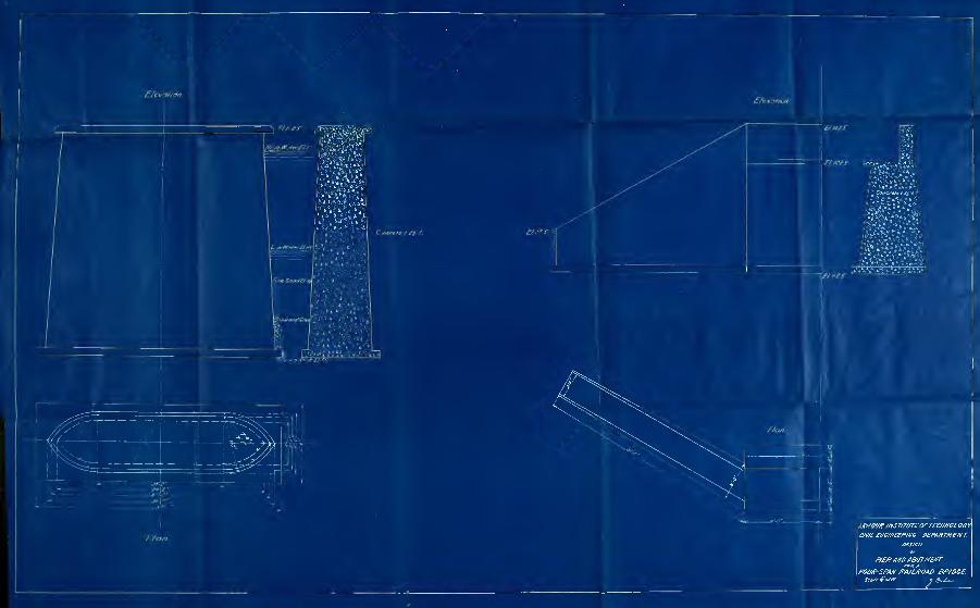

1


Ss-mSi


o ;«qj a *o& in ain o o
^JL