Design of a Reconfigurable Modular Chain for Folding 3D ... · DESIGN OF A RECONFIGURABLE MODULAR...
7
DESIGN OF A RECONFIGURABLE MODULAR CHAIN FOR FOLDING 3D LATTICE STRUCTURES Zhe Xu Department of Mechanical Engineering, Yale University New Haven, Connecticut, USA [email protected] Connor McCann Department of Mechanical Engineering, Yale University New Haven, Connecticut, USA [email protected] Aaron M. Dollar Department of Mechanical Engineering, Yale University New Haven, Connecticut, USA [email protected] ABSTRACT A wide range of engineering applications, ranging from civil to space structures, could benefit from the ability to construct material-efficient lattices that are easily reconfigurable. The challenge preventing modular robots from being applied at large scales is mainly the high level of complexity involved in duplicating a large number of highly integrated module units. We believe that reconfigurability can be more effectively achieved at larger scales by separating the structural design from the rest of the functional components. To this end, we propose a modular chain-like structure of links and connector nodes that can be used to fold a wide range of 2D or 3D structural lattices that can be easily disassembled and reconfigured when desired. The node geometry consists of a diamond-like shape that is one twelfth of a rhombic dodecahedron, with magnets embedded on the faces to allow a forceful and self-aligning connection with neighboring links. After describing the concept and design, we demonstrate a prototype consisting of 350 links and experimentally show that objects with different shapes can be successfully approximated by our proposed chain design. INTRODUCTION Self-reconfigurable modular robots contain a number of identical unit modules and are generally intended to change shapes and functions through reconfiguring their modules with respect to different applications. However, this desirable reconfiguration ability comes with a high cost since each individual module requires independent actuation, communication, power, and even sensing. We believe that the benefit of the reconfigurable ability does not have to be bonded to complicated modular robot designs that generally require a high degree of integration and miniaturization of both mechanical and electronic components. Instead, we argue that some of the intended benefits can be achieved by developing low-cost, light-weight, and reconfigurable modular materials that can be repeatedly used to construct the skeleton of different structures without requiring individual sensing/actuation, but can instead be robotically assembled/disassembled. The general approach of our proposed method is based on a concept in which a continuous prefabricated chain of links is deposited and connected to itself at joint nodes, producing structural lattices in nearly arbitrary configurations that can be disassembled and reconfigured when desired. Our design concept can be seen as a sort of 3D printer for sparse lattices, in which a robotic manipulator arm/small construction robot lays down/carries the links of a passive (non-robotic) continuous chain to create programmed truss lattices using a hierarchy of sub-modules all formed from a single chain of links and joints. The concept will be similar to modern 3D printers that lay down a heated and extruded thread of ABS thermoplastic (i.e. Fused Deposition Modeling) onto a substrate to create arbitrary 3D structures. Instead, we will lay down a chain of rigid links Proceedings of the ASME 2016 International Design Engineering Technical Conferences and Computers and Information in Engineering Conference IDETC/CIE 2016 August 21-24, 2016, Charlotte, North Carolina DETC2016-59496 1 Copyright © 2016 by ASME Downloaded From: http://proceedings.asmedigitalcollection.asme.org/pdfaccess.ashx?url=/data/conferences/asmep/90696/ on 02/03/2017 Terms of Use: http://www.asme.org/abo
Transcript of Design of a Reconfigurable Modular Chain for Folding 3D ... · DESIGN OF A RECONFIGURABLE MODULAR...

DESIGN OF A RECONFIGURABLE MODULAR CHAIN FOR FOLDING 3D LATTICE STRUCTURES
Zhe Xu Department of Mechanical Engineering,
Yale University New Haven, Connecticut, USA
Connor McCann Department of Mechanical Engineering,
Yale University New Haven, Connecticut, USA
Aaron M. Dollar Department of Mechanical
Engineering, Yale University
New Haven, Connecticut, USA [email protected]
ABSTRACT A wide range of engineering applications, ranging from
civil to space structures, could benefit from the ability to
construct material-efficient lattices that are easily
reconfigurable. The challenge preventing modular robots from
being applied at large scales is mainly the high level of
complexity involved in duplicating a large number of highly
integrated module units. We believe that reconfigurability can
be more effectively achieved at larger scales by separating the
structural design from the rest of the functional components. To
this end, we propose a modular chain-like structure of links and
connector nodes that can be used to fold a wide range of 2D or
3D structural lattices that can be easily disassembled and
reconfigured when desired. The node geometry consists of a
diamond-like shape that is one twelfth of a rhombic
dodecahedron, with magnets embedded on the faces to allow a
forceful and self-aligning connection with neighboring links.
After describing the concept and design, we demonstrate a
prototype consisting of 350 links and experimentally show that
objects with different shapes can be successfully approximated
by our proposed chain design.
INTRODUCTION Self-reconfigurable modular robots contain a number of
identical unit modules and are generally intended to change
shapes and functions through reconfiguring their modules with
respect to different applications. However, this desirable
reconfiguration ability comes with a high cost since each
individual module requires independent actuation,
communication, power, and even sensing. We believe that the
benefit of the reconfigurable ability does not have to be bonded
to complicated modular robot designs that generally require a
high degree of integration and miniaturization of both
mechanical and electronic components. Instead, we argue that
some of the intended benefits can be achieved by developing
low-cost, light-weight, and reconfigurable modular materials
that can be repeatedly used to construct the skeleton of different
structures without requiring individual sensing/actuation, but
can instead be robotically assembled/disassembled.
The general approach of our proposed method is based on
a concept in which a continuous prefabricated chain of links is
deposited and connected to itself at joint nodes, producing
structural lattices in nearly arbitrary configurations that can be
disassembled and reconfigured when desired. Our design
concept can be seen as a sort of 3D printer for sparse lattices, in
which a robotic manipulator arm/small construction robot lays
down/carries the links of a passive (non-robotic) continuous
chain to create programmed truss lattices using a hierarchy of
sub-modules all formed from a single chain of links and joints.
The concept will be similar to modern 3D printers that lay
down a heated and extruded thread of ABS thermoplastic (i.e.
Fused Deposition Modeling) onto a substrate to create arbitrary
3D structures. Instead, we will lay down a chain of rigid links
Proceedings of the ASME 2016 International Design Engineering Technical Conferences and Computers and Information in Engineering Conference
IDETC/CIE 2016 August 21-24, 2016, Charlotte, North Carolina
DETC2016-59496
1 Copyright © 2016 by ASME
Downloaded From: http://proceedings.asmedigitalcollection.asme.org/pdfaccess.ashx?url=/data/conferences/asmep/90696/ on 02/03/2017 Terms of Use: http://www.asme.org/about-asme/terms-of-use

and joints (with appropriately designed connectors) to create
lattice structures. To ensure rigidity, sub-units consisting of
links folded to planar triangles will be built upon and used to
form three-dimensional rigid substructures, which will be
expanded to produce “large” (i.e. many-unit) target three-
dimensional structures, all using a single compact general-
purpose platform.
The concept provides a means of custom fabrication of
structural trusses and lattices based on a simple and generic
base material. By starting with a densely-packed spool of
linkage chain, structures can be efficiently “deployed” in
customizable configurations and geometries to meet immediate
fabrication needs, and then reused/reconfigured for successive
applications (see Fig. 1). The approach can be implemented in
any number of size scales and materials, thereby cutting across
many application domains, from millimeter-scale segment
lengths for small part construction, to meter-scale segments for
civil structures.
In the following sections, we first review related work, and
then detail the important aspects of our design. After this, the
two different prototyping processes are described in section IV.
We finish by validating the efficacy of our proof-of-concept
design by demonstrating the folding process of five basic
geometries in section V.
RELATED WORK In order to position our proposed design concept, in this
section we briefly review the previous works that are most
relevant to our project. The existing limitations of these works
are not meant to be critical, but rather serve as the driving
forces during the formation of our design concept.
Reconfigurable/Modular Robots A variety of modular robots have been successfully
designed and prototyped in the past two decades. As thoroughly
summarized in a recent review [1], although each of them
possesses distinctive shapes and features, none of them were
produced in large quantities, preventing researchers from fully
exploring the possible applications of modular robots at a large
scale.
Even if a number of modular robots can transform into a
large robot/structure, a significant portion of these modular
units will be required to serve as the internal structure
maintaining the integrity of the entire shape. For those modules
that are only used as support materials inside a larger
robot/structure, it is a waste to equip them with the same
number of sensors and actuators compared to the ones serving
more functional purposes. In fact, the mechanical strength of
those modular robots may have already been compromised
when complicated electronics and actuators are densely packed
inside them. This may prevent them from forming any large
shape in the first place.
Swarm Robots Recently, over a thousand swarm robots have been
deployed to demonstrate impressive assembly behaviors on a
2D surface [2]. The large number of these robots makes the
entire system a good resource to investigate how biological
assembly occurs in nature. But for the purpose of building 3D
structures, these swarm robots cannot use themselves as the
building blocks, but have to carry and manipulate separate
construction materials from somewhere else. Highly distributed
tasks among many collaborative robots might be an optimum
solution to collect materials and build different types of habitats
in nature, but may not be suitable for constructing large
structures when modular building blocks are pre-fabricated.
Origami-inspired Folding
Deployable origami-inspired panel folding can realize the
reversible transformation between 2D and 3D shapes [3], but
sandwiching techniques are often required in order to make the
folded 3D structure strong enough to withstand external loads
[4]. In addition, once the mountain/valley creases are
determined, the bi-state feature of the origami folding only
allows the 2D panel to form a designated 3D structure.
Compared to origami folding, our proposed method allows
reversible transformations between 1D chain, 2D plane, and 3D
lattice structures which further improves the compactness of the
folding technique.
Programmable Matter & Cellular Materials The concept of the programmable matter is that the same
amount of the material can be used to form different shapes
without being consumed by the formation of any permanent
fixed structure. However most of the design concepts are still
at the simulation stage and can only be demonstrated with
magnetic fluid.
Figure. 1. PICTURES OF OUR PROOF-OF-CONCEPT DESIGN. (a) 293 LINKS ARE USED IN THE FOLDING OF THE PYRAMID SHAPE. (b) A SPOOL OF THE MODULAR CHAIN.
2 Copyright © 2016 by ASME
Downloaded From: http://proceedings.asmedigitalcollection.asme.org/pdfaccess.ashx?url=/data/conferences/asmep/90696/ on 02/03/2017 Terms of Use: http://www.asme.org/about-asme/terms-of-use
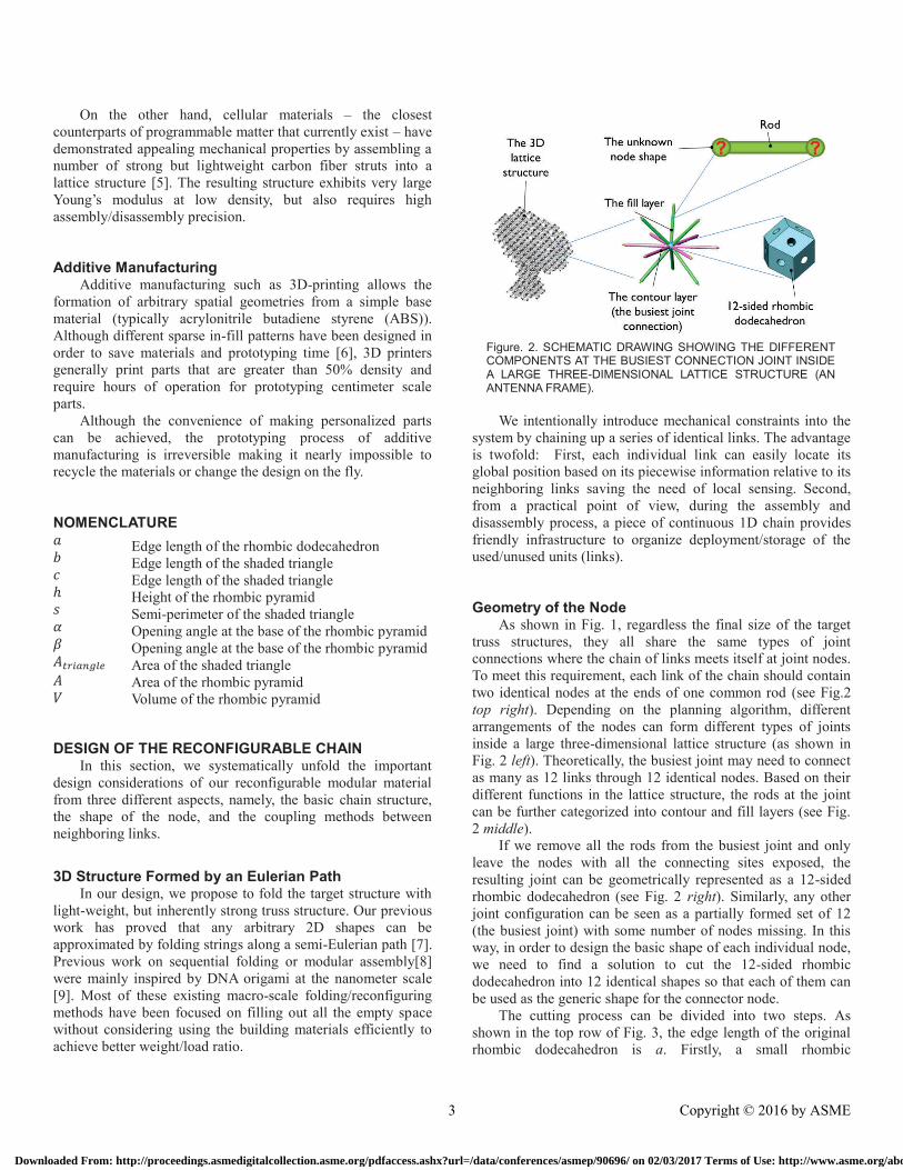
Figure. 2. SCHEMATIC DRAWING SHOWING THE DIFFERENT COMPONENTS AT THE BUSIEST CONNECTION JOINT INSIDE A LARGE THREE-DIMENSIONAL LATTICE STRUCTURE (AN ANTENNA FRAME).
On the other hand, cellular materials – the closest
counterparts of programmable matter that currently exist – have
demonstrated appealing mechanical properties by assembling a
number of strong but lightweight carbon fiber struts into a
lattice structure [5]. The resulting structure exhibits very large
Young’s modulus at low density, but also requires high
assembly/disassembly precision.
Additive Manufacturing
Additive manufacturing such as 3D-printing allows the
formation of arbitrary spatial geometries from a simple base
material (typically acrylonitrile butadiene styrene (ABS)).
Although different sparse in-fill patterns have been designed in
order to save materials and prototyping time [6], 3D printers
generally print parts that are greater than 50% density and
require hours of operation for prototyping centimeter scale
parts.
Although the convenience of making personalized parts
can be achieved, the prototyping process of additive
manufacturing is irreversible making it nearly impossible to
recycle the materials or change the design on the fly.
NOMENCLATURE
!
"
ℎ
$
%
&
'()*+,-./
'
0
DESIGN OF THE RECONFIGURABLE CHAIN In this section, we systematically unfold the important
design considerations of our reconfigurable modular material
from three different aspects, namely, the basic chain structure,
the shape of the node, and the coupling methods between
neighboring links.
3D Structure Formed by an Eulerian Path In our design, we propose to fold the target structure with
light-weight, but inherently strong truss structure. Our previous
work has proved that any arbitrary 2D shapes can be
approximated by folding strings along a semi-Eulerian path [7].
Previous work on sequential folding or modular assembly[8]
were mainly inspired by DNA origami at the nanometer scale
[9]. Most of these existing macro-scale folding/reconfiguring
methods have been focused on filling out all the empty space
without considering using the building materials efficiently to
achieve better weight/load ratio.
We intentionally introduce mechanical constraints into the
system by chaining up a series of identical links. The advantage
is twofold: First, each individual link can easily locate its
global position based on its piecewise information relative to its
neighboring links saving the need of local sensing. Second,
from a practical point of view, during the assembly and
disassembly process, a piece of continuous 1D chain provides
friendly infrastructure to organize deployment/storage of the
used/unused units (links).
Geometry of the Node
As shown in Fig. 1, regardless the final size of the target
truss structures, they all share the same types of joint
connections where the chain of links meets itself at joint nodes.
To meet this requirement, each link of the chain should contain
two identical nodes at the ends of one common rod (see Fig.2
top right). Depending on the planning algorithm, different
arrangements of the nodes can form different types of joints
inside a large three-dimensional lattice structure (as shown in
Fig. 2 left). Theoretically, the busiest joint may need to connect
as many as 12 links through 12 identical nodes. Based on their
different functions in the lattice structure, the rods at the joint
can be further categorized into contour and fill layers (see Fig.
2 middle).
If we remove all the rods from the busiest joint and only
leave the nodes with all the connecting sites exposed, the
resulting joint can be geometrically represented as a 12-sided
rhombic dodecahedron (see Fig. 2 right). Similarly, any other
joint configuration can be seen as a partially formed set of 12
(the busiest joint) with some number of nodes missing. In this
way, in order to design the basic shape of each individual node,
we need to find a solution to cut the 12-sided rhombic
dodecahedron into 12 identical shapes so that each of them can
be used as the generic shape for the connector node.
The cutting process can be divided into two steps. As
shown in the top row of Fig. 3, the edge length of the original
rhombic dodecahedron is ǡ. Firstly, a small rhombic
Edge length of the rhombic dodecahedron
Edge length of the shaded triangle
Edge length of the shaded triangle
Height of the rhombic pyramid
Semi-perimeter of the shaded triangle
Opening angle at the base of the rhombic pyramid
Opening angle at the base of the rhombic pyramid
Area of the shaded triangle
Area of the rhombic pyramid
Volume of the rhombic pyramid
3 Copyright © 2016 by ASME
Downloaded From: http://proceedings.asmedigitalcollection.asme.org/pdfaccess.ashx?url=/data/conferences/asmep/90696/ on 02/03/2017 Terms of Use: http://www.asme.org/about-asme/terms-of-use

dodecahedron (with edge length equals /3 , 3 > 1 ) is
concentrically placed inside the original one. And then, the four
vertices from one face of the small rhombic dodecahedron are
connected with the corresponding vertices from the outside
rhombic dodecahedron. The shape bounded by the two faces
and four edges is a rhombic pyramid. It has four symmetrically
identical faces and is hereinafter used as the basic shape for our
node design.
After adding a simple base with a socket for the rod
connection, 12 of these rhombic pyramid nodes can seamlessly
form the busiest connection joint without any assembly issues
(see Fig. 3 bottom row). Although we found other basic shapes
that can also be used to construct the node and form the same
joint, the rhombic pyramid shape allows us to maximize the
contact area between the neighboring nodes.
As the uniformly extruded rod is inherently stronger and
stiffer than the connection joints inside a reconfigurable lattice
structure, the contact area between the two nodes is critical to
the stability of the entire structure. Since our proposed design is
aiming for implementing the reconfiguration ability into the
structures that are at either small or large scale, we are
interested in knowing how the size of the node design can
affect the contact area between nodes.
As shown in Fig. 4, the two opening angles at the base of
the rhombic pyramid are:
% = $6378 (√6/3) (1)
& = $6378(√3/3) (2)
with the height
ℎ = √6 /3 (3)
we can calculate the edge lengths as follows
! = @( ∗ $63&)B + ℎB = √15 /3 (4)
" = @( ∗ $63%)B + ℎB = √12 /3 (5)
Based on Heron's formula, the area of the shaded triangle can
be calculated based on the lengths of its sides by using the
following equation:
'()*+,-./ = @$($ − )($ − !)($ − ") = √11 B/6 (6)
where $ = +GHGI
B is the defined as the semi-perimeter of the
shaded triangle.
Therefore, the area A and volume V of the rhombic
pyramid are:
' = 4 ∙ '()*+,-./ = 2√11 B/3 (7)
0 = 4√3 L/27 (8)
Besides distributing and guiding the contact forces, the
plain contact surfaces themselves cannot directly provide any
coupling forces between neighboring nodes. However its size
determines the type of the latching mechanism that can be
implemented in order to provide required the coupling forces.
Therefore these two parameters (A and V) are important design
factors.
Figure. 4. THE IMPORTANT DIMENSIONS OF OUR NODE DESIGN. (a) THE RHOMBIC PYRAMID WITH FOUR SYMMETRICALLY IDENTICAL FACES. (b) SCHEMATIC DRAWING OF THE NODE DESIGN SHOWING THE CRITICAL ASSEMBLY ANGLES.
Figure. 3. THE FORMATION OF THE BASIC NODE GEOMETRY. TOP ROW: A SMALLER RHOMBIC DODECOHEDRON IS FIRST FIT INTO THE CENTER OF THE BUSIES CONNECTION JOINT. BOTTOM ROW: AFTER A SERIES OF CUTTING PROCESS, THE RHOMBIC PYRAMID SHAPE IS SELECTED TO FORM BASIC GEOMETRY OF NODE DESIGN.
Figure. 5. TWO DIFFERENT TYPES OF MAGNETIC COUPLING USED IN OUR PROTOTYPE (a) TYPE-I – EMBEDDING PAIRED MAGNETS DIRECTLY AT THE CONTACTING SITES. (b) TYPE-II – TRANSMITTING MAGNETIC FORCES THROUGH THE NODE MADE OF FERROUS MATERIALS. NOTE: THE CENTRAL HOLE IS FOR ANCHORING CONNECTING STRINGS.
4 Copyright © 2016 by ASME
Downloaded From: http://proceedings.asmedigitalcollection.asme.org/pdfaccess.ashx?url=/data/conferences/asmep/90696/ on 02/03/2017 Terms of Use: http://www.asme.org/about-asme/terms-of-use

Figure. 7. 2D SIMULATION OF THE MAGETIC FIELDS BY USING TYPE-II COUPLING METHOD. (a) ALTERNATING THE POLES AT THE TWO ENDS OF EACH ROD. (b) 2D SIMULATION OF THE MAGNETIC FIELDS AT DIFFERENT CONNECTION JOINTS IN A 3D RECONFIGURABLE LATTICE STRUCTURE.
Figure. 8. The PROTOTYPING PROCESS OF NODES VIA 3D PRINTING. (a) A TRAY OF 110 3D-PRINTED NODES. (b) EXAMPLE OF A SEPARATE LINK. (c)–(j) VARIATIONS OF 2D AND 3D STRUCTURES FOLDED BY A 14-LINK CHAIN.
Figure. 6. POSSIBLE CONNECTION JOINTS SUPPORTED BY TYPE-I COUPLING METHOD. NOTE: EXCEPT FOR THE START AND THE END, ALL THE OTHER CONNECTION JOINTS HAVE EVEN NUMBER OF NODES INSIDE ANY FOLDED LATTICE STRUCTURE. RODS WERE REMOVED FOR BETTER VISIBILITY OF THE NODES.
Connection between the Nodes
The coupling between adjacent nodes is the key to
maintaining the rigidity of the reconfigurable lattice structure.
Depending on the size of the resulting link design, they are two
major locations that can be potentially used to incorporate
different coupling methods as shown in Fig. 5.
When the size of the target structure is larger than the
centimeter scale, the type-I method is a good option since
contact sites are abundant for implementing different types of
surface features for latching mechanisms [1]. Currently we
chose small neodymium magnet (3.2mm in diameter, 1.6mm in
thickness, N52 grade) to validate our design concept due to its
easy implementation, good strength (2.5N magnet-magnet
pulling forces), and self-alignment features.
As shown in Fig. 6, the four faces of the rhombic pyramid
provide an ideal platform for the alternating male-female
coupling pattern. Different types of connection joints can be
easily formed upon contact.
As the size of the target structure getting smaller than the
centimeter scale, the size of the node and rod will also need to
be reduced accordingly. Therefore fewer contact surfaces will
be available for implementing type-I coupling and locations of
the coupling sites need to be further pushed back towards the
middle of the rod. In this case, adopting type-II coupling
methods can be a good way for latching the two adjacent nodes.
To this end, magnets with alternating poles can be directly
attached to the ends of a rod leaving the contact sites between
nodes plain. As long as the nodes are made of ferrous materials
that possess good magnetic permeability. Simulation of the
magnetic field confirmed that the resulting magnetic forces can
help the formation of different joints inside a folded 3D
structure (see Fig. 7).
It is important to recall that our proposed folding path
follows a semi-Eulerian path, and therefore except for the start
and end, all the connection joints have even number of nodes to
allow pairing between alternating poles.
Although we used permanent magnets for both of the two
coupling methods, the same idea can be upgraded to
incorporate a variety of controllable interlocking/latching
mechanisms, e.g. the electropermanent magnetic connector
[10], the mechanical latching mechanism [11], [12], and even
the reversible soldering connector [1].
FABRICATION PROCESS As will be demonstrated in the Experimental section, our
proposed modular material requires hundreds of links during
the folding process. Based on the two different types of the
coupling methods, we also experimentally explored two rapid
5 Copyright © 2016 by ASME
Downloaded From: http://proceedings.asmedigitalcollection.asme.org/pdfaccess.ashx?url=/data/conferences/asmep/90696/ on 02/03/2017 Terms of Use: http://www.asme.org/about-asme/terms-of-use

Figure. 9. PROTOTYPING PROCESS OF NODES BY USING COLD-CASTING METHOD. (a) 3D-PRINTED POSITIVES AND THE SILICONE RUBBER MOLD. (b) & (c) COLD-CASTED PARTS MADE FROM THE MIXTURE OF FINE IRON POWDER AND RESINS. (d) COMPARISON OF MAGNETIC FORCES WITH NODES MADE OF DIFFERENT MATERIALS. NOTE: EACH STEEL BALL WEIGHTS 8.4 GRAMS. THE RED ROD IS THE OFF-THE-SHELF GEOMAG PART.
Figure.10. EXAMPLE OF THE FOLDING PROCESS. (a) THE SEPARATE FOLDING PATHS FOR CONSTRUCTUING DIFFERENT LAYERS OF A PYRAMID. (b) SNAPSHOTS SHOWING THE DESMONSTATION OF PLANNED FOLDING PROCESS.
prototyping methods in order to maximize their performance in
different application scenarios. We believe a good all-around
design should also consider the manufacturing methods.
The type-I coupling method has the magnetic latching
mechanism directly embedded at the contact sites. Therefore it
does not require special materials for the nodes. As shown in
Fig. 8. An array of 110 nodes can be printed in 36 hours by
using Stratasys’s uPrint. Each individual link weights 5.7
grams, and is composed of two 3D printed nodes and 53 mm
long ABS tube. As shown in Fig. 8 (c) and (d), one chain can be
folded into a variety of objects ranging from 2D to 3D shapes
with only 14 links.
As we mentioned in the previous section, type-II coupling
requires ferrous materials with good magnetic permeability to
allow the transmission of the magnetic fields between
neighboring nodes. Instead of using CNC machined metal
nodes, we found that cold-casting method can enable us to cost-
efficiently fabricate a large number of ferrous parts with good
precision in a short period of time (see Fig. 9 (a)-(c)). Cold-
casting is a well-established molding technique involving
mixing the epoxy resins with a small amount of metal powder,
and is mainly used by artists to fabricate metallic looking
statues at low cost. In our case, we used high metal-resin
volume ratio (99.9% iron powder/epoxy resin >7:1) and
therefore each cold-casted node weights around 1.2 grams --
only 18.2% percent of the CNC machined one -- but can still
effectively direct magnetic flux as well as the CNC machined
one as shown in Fig. 9 (d).
However, compared to the 3D printing method used by our
type-I node design, the cold-casting method needs two separate
molding processes for the silicone mold and final parts,
respectively. At our current design stage, the latter requires
more manual work and prototyping time. Therefore in order to
efficiently demonstrate our proof-of-concept design, we chose
type-I nodes for the rest of the experiments.
EXPERIMENTAL EVALUATION In order to demonstrate the reconfigurability of our
proposed design, we prototyped 350 links (700 nodes) based on
the type-I coupling method due to its relatively efficient
prototyping process. The resulting modular chain can be
compactly organized and stored by using a spool (see Fig. 1(b))
and folded into a variety of shapes by following different
folding paths as demonstrated in Fig. 10 and 11.
In contrast to hours of fabrication time required by the 3D-
printing process, once the folding path of a target structure is
planned, all of our demonstrated structures can be quickly
folded in a few minutes. In addition, the disassembly process
takes even less time since the chain structure can automatically
guide the unfolding process by moving from one unlatched link
to the other sequentially.
As shown in Fig. 12, our design concept can also be scaled
up to form much larger structures. The reconfigurability of the
chain structure allows the same number of links (1554 of 0.3m
strut) to be constructed into either two solar panels or one
antenna frame. Since the links are all connected by compliant
strings in a piecewise manner, the extra/excessive links can be
easily attached/removed. In this case, the shell of a space
habitat can be built by extending the chain to 7560 links.
6 Copyright © 2016 by ASME
Downloaded From: http://proceedings.asmedigitalcollection.asme.org/pdfaccess.ashx?url=/data/conferences/asmep/90696/ on 02/03/2017 Terms of Use: http://www.asme.org/about-asme/terms-of-use

Figure.12. POTENTIAL APPLICATIONS OF OUR PROPOSED CHAIN DESIGN IN SPACE EXPLORATION. NOTE: THE FRAMES OF THE ANTENNA AND SOLAR PANEL ARE ALL FOLDED BY THE SAME CHAIN WITH 1554 LINKS.
Figure.11. VARIATIONS OF FOLDED SHAPES BOTH IN 2D AND 3D (329-LINK).
With an active cell mechanism [13], the chain can also
morph into shorter one, so that smaller structures can also be
formed without the need of changing the chain. If we reduce
the length of each link to half its original length, and remove
3534 links, the same chain can be used to form a chassis of a
planetary rover.
CONCLUSION AND FUTURE WORK We have designed and prototyped a new type of
reconfigurable modular material that can be easily
deployed/recycled to fold/unfold 3D lattice structures.
Important design criteria were detailed about the shape of the
nodes, the coupling between nodes, and the prototyping
methods for two different types of magnetic latching
mechanisms. We experimentally demonstrated that our design
can facilitate the formation of different connection joints
needed for building 3D structures, and the reconfigurability of
our design can be clearly observed in both small (14-link) and
large (350-link) structures. Due to its light-weight and high
pre/post deployed volume ratio, we believe that our proposed
design will be beneficial to a number of applications, including
space exploration, construction in remote environments, and
others where material weight and therefore reconfigurability is
at a premium.
In future work, we will further improve the strength of
coupling forces between connector nodes via mechanical
latching mechanisms, as well as designing algorithms for
structures of varying lattice density and strength. We will also
be working towards a robotic “printer” using the chain to
autonomously lay down lattice components to construct
structures of arbitrary desired shapes.
ACKNOWLEDGMENT
The authors would like to thank Devin Balkcom and Corey
O’Hern for their input during the development of this concept.
REFERENCES
[1] J. Neubert, A. Rost, and H. Lipson, “Self-soldering connectors for
modular robots,” IEEE Trans. Robot., vol. 30, no. 6, pp. 1344–1357, 2014.
[2] M. Rubenstein, A. Cornejo, and R. Nagpal, “Programmable self-
assembly in a thousand-robot swarm,” Science (80-. )., vol. 345, no. 6198, pp. 795–799, 2014.
[3] D. J. Balkcom and M. T. Mason, “Robotic origami folding,” Int. J.
Rob. Res., vol. 27, no. 5, pp. 613–627, 2008. [4] M. Schenk and S. D. Guest, “Origami Folding: A Structural
Engineering Approach,” Origami 5 Fifth Int. Meet. Origami Sci.
Math. Educ., pp. 1–16, 2011. [5] K. C. Cheung and N. Gershenfeld, “Reversibly Assembled Cellular
Composite Materials,” Science (80-. )., vol. 341, no. September, pp.
1219–1221, 2013. [6] S. Mueller, S. Im, S. Gurevich, A. Teibrich, L. Pfisterer, F.
Guimbretière, and P. Baudisch, “WirePrint: 3D printed previews for
fast prototyping,” UIST ’14 Proc. 27th Annu. ACM Symp. User interface Softw. Technol., no. Figure 2, pp. 273–280, 2014.
[7] Z. Li, D. J. Balkcom, and A. M. Dollar, “Rigid 2D space-filling folds
of unbroken linear chains,” in Proceedings - IEEE International
Conference on Robotics and Automation, 2013, pp. 551–557.
[8] S. T. Griffith, “Growing Machines,” Ph.D. dissertation,
Massachusetts Institute of Technology, 2004. [9] P. A. Pevzner, H. Tang, and M. S. Waterman, “An Eulerian path
approach to DNA fragment assembly.,” Proc. Natl. Acad. Sci. U. S. A., vol. 98, no. 17, pp. 9748–53, 2001.
[10] K. C. Cheung, E. D. Demaine, J. R. Bachrach, and S. Griffith,
“Programmable assembly with universally foldable strings (moteins),” IEEE Trans. Robot., vol. 27, no. 4, pp. 718–729, 2011.
[11] A. Sproewitz, M. Asadpour, Y. Bourquin, and A. J. Ijspeert, “An
active connection mechanism for modular self-reconfigurable robotic systems based on physical latching,” in Proceedings - IEEE
International Conference on Robotics and Automation, 2008, pp.
3508–3513. [12] N. Eckenstein and M. Yim, “Design, principles, and testing of a
latching modular robot connector,” in IEEE International Conference
on Intelligent Robots and Systems, 2014, pp. 2846–2851.[13] J. P. Swensen, A. I. Nawroj, P. E. I. Pounds, and A. M. Dollar,
“Simple, scalable active cells for articulated robot structures,” in
Proceedings - IEEE International Conference on Robotics and Automation, 2014, pp. 1241–1246.
7 Copyright © 2016 by ASME
Downloaded From: http://proceedings.asmedigitalcollection.asme.org/pdfaccess.ashx?url=/data/conferences/asmep/90696/ on 02/03/2017 Terms of Use: http://www.asme.org/about-asme/terms-of-use