Design of a Prototype Miniature Autonomous
5
PrOceedingS of the 2003 IEEBRSJ Inn. Conference w1 intelligent Robots and Systems Las Veaas. Nevada October 2003 Design of a Prototype Miniature Autonomous Underwater Vehicle Aditya S. Gadre Jared J . Mach Daniel J . Stilwell Carl E . Wick The Bradley Department of Electrical and Computer Engineering Virginia Polytechni c Inst itu te and St at e Unive rsi ty Systems Engineering Department United States Naval Academy Bla cksb urg, VA 24061 {agadre, jmach, stilwell}@ut.edu, Abstmct- Platoons of cooperating autonomous underwa- ter vehicles have the potential to contribute significantly to scientific investigations in the marine environment. Pla- toon s of vehicles can survey large areas, adaptively track and measure timevarying processes such as tidal fronts and al- gal blooms, and they ar e robust to single-point failures. We have developed a prototype miniature low-cost autonomous underwater vehicle to address the platform requirements of these missions. The vehicle is designed as a test-bed for the development of distributed control and estimation al- gorithms, an d for experiments in advanced navigation an d control. I . INTRODUCTION Plat oons o f cooperating autonomous vehicles hav e signif- icant and well-know advantag es over single vehicles oper- ating independently. Cooperating vehicles can rapidly sur- vey large areas, they can survey in four dimensions (space and time), and they are robust to single point failures. It is also hypothesized that the individual vehicles in a pla- toon o f cooperating vehicles could be less expensive and less sophisticated than vehicles designed to operate inde- pendently. Most research on multiple cooperating vehicles is con- ducted using terrestrial vehicles. Yet the marine and ocean science communities would benefit significantly from suc- cessf ul use of cooperating underwater vehicles. Potenti al applicat ions include su rveying chemica l plumes, mapping oceanographic processes (e.g., tidal front), and mapping bi- ological populations. For underwater vehicle applications, the complexity and cost of deployments with multiple un - derwater vehicles is a major factor limiting experimental activities. To facilitate experiments with platoons of coop erating autonomous underwater vehicles (AUVs), we have embarked on a program to develop a miniature low-cost AUV that operates robustly in the fi eld . Our prototy pe miniature AUV is described herein. Oth er small AUVs, such as REMUS [I] and Ranger (2 1 could be utilized for multi-vehicle research, but their costs and/ or infrastructure requir ements are prohibitive. At a cost of less than $3,000 in parts, the prototype AUV de- scribed herein is dramatically less expensive than currently D. J. Stilweli gratefully acknowledges the support of the Na - tional Science Found ation via grant IIS0238092, Office of Naval Re- search via grant N00014-03-1-0444, nd the Woodrow W. Everett, Jr . SCEEE Development Fund in cooperation with the Southeastern Consortium of Electrical Engineering Mueatom. Annapolis, MD 21402 wicL&hsn,a. edu available AUVs. Th e challenges o f acqui ring an d deploying a platoon of AUV s are t he principle motivation fo r developing th e AUV described herein. These challenges are exemplifie d b y the very limited literature of reported experiments with pla- toons of underwa ter vehicles. A notabl e exception was de- scribed in (31. Leader-follower control was demonstrated using Odyssey vehicles with a modifie d ultra-short baseline transponder on the lead vehicle. Though the control algo- rithm for the follower vehicles was somewhat a d hoc, the system displayed significant robustness. In 141, the devel- opment of a ne w auto nomo us underwater vehicle designed for laboratory experiments with platoons of vehicles is de- scribed. Field operations where multiple AUVs operate in th e same area, but are otherwise uncoordinated, have also been reported [Si, 6 1 . . , . , ... - I . . ' . j . . - . ... . Fig. 1 . filly assembled A W . Fig. 2. Hull and nose removed. 11. A MlNiATURE AUV Th e principal goals of our miniature AUV design effort is to produ ce a vehic le tha t is small, inexpe nsive, easy to deploy, and yet fully functional as a platform for marine
-
Upload
dibbendu-roy -
Category
Documents
-
view
219 -
download
0
Transcript of Design of a Prototype Miniature Autonomous

8/2/2019 Design of a Prototype Miniature Autonomous
http://slidepdf.com/reader/full/design-of-a-prototype-miniature-autonomous 1/5
PrOceedingS of the 2003 IEEBRSJInn.Conference w1 intelligent Robots and Systems
Las Veaas. Nevada October2003
Design of a Prototyp e Miniature AutonomousUnderwater Vehicle
Adi tya S. Gadre Jared J. Mach Daniel J. Stilwell Carl E. Wick
The Bradley Department of Electrical and Computer EngineeringVirginia Polytechnic Inst itute and State University
Systems Engineering DepartmentUnited States Naval Academy
Blacksburg, VA 24061
{agadre, jmach, stilwell}@ut.edu,
Abstmct- Platoons of cooperating autonomous underwa-
ter vehicles have the potential to contribute significantly
to scientific investigations in the marine environment. Pla-toon s of vehicles can survey large areas, adaptively track and
measure timevarying processes such as tidal fronts and al-
gal blooms, and they ar e robust to single-point failures. We
have developed a prototype miniature low-cost autonomous
underwater vehicle to address the platform requirements ofthese missions. The vehicle is designed as a test-bed for
the development of distributed control and estimation al-gorithms, and for experiments in advanced navigation andcontrol.
I. INTRODUCTION
Platoons of cooperating autonomous vehicles have signif-
icant and well-know advantages over single vehicles oper-
ating independently. Cooperating vehicles can rapidly sur-
vey large areas, they can survey in four dimensions (space
and time), and they are robust to single point failures. Itis also hypothesized that the individual vehicles in a pla-
toon of cooperating vehicles could be less expensive andless sophisticated than vehicles designed to operate inde-
pendently.
Most research on multiple cooperating vehicles is con-
ducted using terrestrial vehicles. Yet the marine and ocean
science communities would benefit significantly from suc-
cessful use of cooperating underwater vehicles. Potential
applications include surveying chemical plumes, mapping
oceanographic processes (e.g., tidal front), and mapping bi-
ological populations. For underwater vehicle applications,
the complexity and cost of deployments with multiple un-
derwater vehicles is a major factor limiting experimental
activities. To facilitate experiments with platoons ofc o o perating autonomous underwater vehicles (AUVs), we have
embarked on a program to develop a miniature low-cost
AUV tha t operates robustly in the field. Our prototype
miniature AUV is described herein.Other small AUVs, such as REMUS [I] and Ranger (21
could be utilized for multi-vehicle research, but their costs
and/or infrastructure requirements are prohibitive. At a
cost of less than $3,000 in parts, the prototype AUV de-
scribed herein is dramatically less expensive than currently
D. J. Stilweli gratefully acknowledges the support of the Na -tional Science Foundation via grant IIS0238092, Office of Naval Re-search via grant N00014-03-1-0444,nd the Woodrow W. Everett,Jr . SCEEE Development Fund in cooperation with the SoutheasternConsortium of Electrical Engineering Mueatom.
Annapolis, MD 21402
wicL&hsn,a. edu
available AUVs.
The challenges of acquiring and deploying a platoon of
AUVs are the principle motivation for developing the AUV
described herein. These challenges are exemplified by the
very limited literature of reported experiments with pla-
toons of underwater vehicles. A notable exception was de-
scribed in (31. Leader-follower control was demonstrated
using Odyssey vehicles with a modified ultra-short baselinetransponder on the lead vehicle. Though the control algo-
rithm for the follower vehicles was somewhat ad hoc, the
system displayed significant robustness. In 141, the devel-
opment of a new autonomous underwater vehicle designed
for laboratory experiments with platoons of vehicles is de-
scribed. Field operations where multiple AUVs operate in
the same area, but are otherwise uncoordinated, have also
been reported [Si, 61.
. , . , ... -I ..
' . j
. . - . ... .
Fig. 1 . filly assembled A W .
Fig. 2. Hull and nose removed.
11. A MlNiATURE AUV
The principal goals of our miniature AUV design effort
is to produce a vehicle that is small, inexpensive, easy to
deploy, and yet fully functional as a platform for marine

8/2/2019 Design of a Prototype Miniature Autonomous
http://slidepdf.com/reader/full/design-of-a-prototype-miniature-autonomous 2/5

8/2/2019 Design of a Prototype Miniature Autonomous
http://slidepdf.com/reader/full/design-of-a-prototype-miniature-autonomous 3/5
antenna. The inside of the nose cone is hollowed out to al-
low for mounting of sensors that require exposure to water,
such as the sonar altimeter. The nose attaches to the hull
via three dowel pins.
Fig. 5 . Hull and Nare Cane
E. Electronics
Power is provided by a battery stack consisting of 4/3
A size NiMH cells. The battery stack provides 80 watt -
hours at 21.6V. Regulated power at 3.3V, 5V, and 12V is
provided by a miniature switching power regulators (Power
Trends 7 8 S b H C ) . A separate 3V lithium cell powers the
GPS receiver's real-time clock and allows it to save almanac
data. A small mechanical relay is used to open and close
the main battery circuit through a simple shunt switch in
a water tight connector in the forward bulkhead.
The AUV control system is centered around a Rabbit
3000 &bit microcontroller (RCM3200 module), running at44.2 MHz, and programmed in C. The microcontroller in-
terfaces directly with a custom-engineered serial port ex-
pansion card and external 8M B FLASH memory. An u p
grade path to a laptop HD for high density data storage
exists. A block diagram showing the data interfaces with
the microcontroller is shown in Figure 6.
Fig. 6. Control System.
All data communication within t he AUV is implemented
The Rabbit microcontrollersing serial communication.
has six built-in serial ports, and a custom engineered
printed circuit board was designed to provide 5 additional
serial ports. One of the Rabbit's serial ports is multiplexed
to provide 1 x 4 serial port expansion using line drivers
and buffers. A dual UART provides two additional I jO-mapped serial ports: making total number of serial ports
11. Out of these, two serial ports are Rs232 while all others
are TTL level.The propeller is driven with a 24V, 40 watt, brushless DC
motor. A custom-engineered printed circuit board (PCB)
was designed to drive and control the brushless motor along
with the three servo motors. It performs electronic com-
mutation of the brushless motor and controls motor v e
locity using a quadrature encoder signal from the motor
and pulse-width modulation of the motor phase voltages.
The motor controller communicates directly with the Rab-
bit microprocessor over a serial link. The motor controller
sources up to 3 amps at 50 V.
C. Sensors
A custom-engineered printed circuit board enables pro-
cessing of analog sensor signals, including depth trans-ducer, accelerometers, and rategyros . Three-axis accel-
eration is measured by MEMS accelerometers (ADXLlOS),
and 3-axis angular rate is measured by miniature rate gy-
ros (Gyration Micrc-Gyro 100). A network of operational
amplifiers provides signal conditioning, including scaling
and shifting. Analog-to-digital conversion is accomplished
with an 8-channel 12-bit serial ADC (Maxim MAX1270).
A PIC microcontroller manages the AD C conversion pro-
cess, provides digital filtering, and interfaces to the Rabbit
microcontroller via the serial bus. The PIC microcontroller
samples all analog signals at 2 KHz, averages the samples,
and provides them to the Rabbit microcontroller at 10 Hz.
Fast sampling and averaging reduces noise by more than
an order of magnitude.
An off-the-shelf electronic compass (PNI TCM2-20) pro-
vides magnetic heading, pitch, roll, and internal temper-
ature . Pitch and roll measurements are also provided by
accelerometers on the analog sensors card that measure the
gravity vector with respect to body fixed coordinates.
A GPS receiver (Motorola M12 OnCore) provides precise
position when the vehicle is on the surface. The GPS re-
ceiver can provide data in NMEA 0183 data format (at
4800 baud) or Motorola binary format (at 9600 baud).
Since hinary data provides more information faster, it is
used instead of NMEA format. Time-to-first-fix is reduced
by synchronizing time with the Rabbit Microcontroller,
which in turn receives time from the host PC.Use of a GPS receiver for precise navigation implies that
the AUV will periodically surface for a GPS fix. This is a
reasonable assumption given the shallow water applications
for which the AUV is intended. Yet an important consid-
eration is the time-to-first& after the AUV has beensub-
merged and returns t o the surface. If time-to-first-fix is too
long, then the AUV will spend an excessive amount of time
on the surface waiting for a GPS&. To determine time-to-
first.& after the AUV has been submerged, we submerged
644
8/2/2019 Design of a Prototype Miniature Autonomous
http://slidepdf.com/reader/full/design-of-a-prototype-miniature-autonomous 4/5
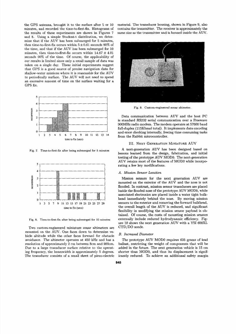
the G PS antenna, brought it, to the surface after 5 or 10
minutes, and recorded the time-to-first-fix. Histograms of
the results of these experiments are shown in Figures 7 and 8. Using a simple Student4 distribution, we deter-
mine that if the AU V has been submerged for 5 minutes,
then time-to-fist -& occurs within 5 *0.61 seconds90% of
the time, and that if the AU V has been submerged for 10
minutes, then time-to-first-fix occurs within 14.67i .0 1seconds 90% of the time. Of course, the applicability of
our results is limited since only a small sample of datawa staken on a single day. These initial experiments suggest
that G PS is a good source of precise navigation data for
shallow-water missions where it is reasonable for the AU V
to periodically surface. The AU V will not need to spend
an excessive amount of time on the surface waiting for a
GPS fix.
I 2 3 4 5 6 7 8 9 1 0 1 1 1 2 1 3 1 4
time 10fix (secs)
Fig. 7. Time-to-first-fix after being submerged for 5 minut-
I
0
1 3 5 7 9 1 1 13 15 17 19 21 23 25 21 29
time to fi x (secs)
Fig. 8. Tim-to-first-fix &er being submerged for 10 minutes
material. The transducer housing, shown in Figure 9, also
contains the transmitter. The receiver is approximately the
same size as the transmitter and is housed inside the AUV.
Fig. 9. Custom-engineered sonar altimeter.
Data communication between AUV and the host PC
is standard Rs232 serial communication over a Freewave
9OOMHz radio modem. The modem operates at 57600 baud
full-duplex (115Khaud total). It implements da ta encoding
and error checking internally, freeing time consuming tasksfrom the Rabbit microcontroller.
111. NEXTGENERATIONINIATURE UV
A next-generation AU V has been designed based on
lessons learned from the design, fabrication, and initial
testing of the prototype AUV MODO. The next-generation
AUV retains most of the features of MODO while incorp-
rating a few key modifications.
A . Mission Sensor Location
Mission sensors for the next generation AUV are
mounted on the exterior of he AU V and the nose is not
flooded. In contrast, mission sensor transducers are placed
inside the flooded nose of the prototype AUV MODO, while
associated electronics are placed inside a water tight bulk-
head immediately behind the nose. By moving mission
sensors to the exterior and removing the forward bulkhead,
the overall length of the AU V is reduced, and significant
flexibility in modifying the mission sensor payload is ob-
tained. Of course, the costs of mounting mission sensors
externally include reduced hydrodynamic efficiency. Fig-ure 10 shows the next generation AUV with a YSI 600XL
TWO custom-engineered miniature sonar altimeters are
mounted on the AUV. One faces down to determine ve-
hicle altitude while the other faces forward for obstacle
avoidance. The altimeter operates at 450 kHz and has a
resolution of approximately 2 cm between 8cm and 9OOcm.
Due to a large transducer surface relative to the operat-
ing frequency, the beamwidth is approximately 5 degrees.
The transducer consists of a small sheet of piezo-electric
CTDlDO sonde.
l?' InCEased Diameter
The prototype A W MODO requires 635 grams of lead
ballast, restricting the weight of components that will be
added in the future. The next generation vehicle is 15 cm
shorter than MODO, and thus its displacement is signif-
icantly reduced. To achieve an additional safety margin
845

8/2/2019 Design of a Prototype Miniature Autonomous
http://slidepdf.com/reader/full/design-of-a-prototype-miniature-autonomous 5/5
hide for complex 3-D sensing,” in Proceedings of he IEEE/MTS
OCEANS, pp. 2043-2045, 2001.
131 H. Singh, J . Catipovic, R. Eastwood, L. Freitag, H. Henricksen,F. Hover, D. Yaerger, J. Bellingham, and B. Moran, “An inte-grated approach to multiple AUV communications, navigation,and docking,” in Proceedings of IEEE/MTS Oceans, (FortLaud.erdale, Florida), pp. 59-64, September 1996.
141 R. Bachmeyer and N. Leonard, “A test-bed for multi AUV exper-iments,” in Proceedings of the the 1Oh International Symposium
on Unmanned Untethered Submersible Technology, (Durham,Ne w Hampshire), August 2001.
Specification
9.6 cm
4 .5 kg (without CTD/DO sonde)
DIMM-PC (133 MH z AMD Elan
SC520)22.2 volt, 142 watt-hour lithium
polymer battery stack
Parameter
Length 76.0 cm
~ i ~ ~ ~ t ~
MassCPU
Power