Design of a Normal Conducting 50 MeV Proton...
9
Design of a Normal Conducting 50 MeV Proton Linac Project Report USPAS – Summer 2014 - High Intensity RF Linear Accelerator Course Captain: Alejandro Castilla Crew: Charlotte Roose Robert Potts Fatma Cagla Ozturk Mert Sekerci Abstract: In this project, our goal is to design a linear accelerator using TRACE3D simulation code and to analyze the evolution of the phase advance, energy, energy gain, transverse and longitudinal beam envelopes. We will describe the three main sections of the lattice: the radiofrequency quadrupole (RFQ), the medium energy beam transport (MEBT), and the drift tube linac (DTL). Given Beam Parameters: Our group was assigned to design a RFQ to produce a 5-MeV beam that would be transported through a 3-m MEBT into a normal conducting DTL. We were given the initial design parameters indicated in Table 1 below. Table 1: Design Parameters RFQ W 5 MeV OUT W 50 MeV I 50 mA , xy ε 15 πmmrad RFQ + MEBT + DTL (N.C.) f 350 MHz long ε 620 πkeVdeg RFQ E peak 1.8E k MEBT 3 m Focusing Electromagnetic Quadrupoles max B 0.8 T DTL 50 2 Ω/m=ZT T 0.8 /6 ACC peak E E =
Transcript of Design of a Normal Conducting 50 MeV Proton...
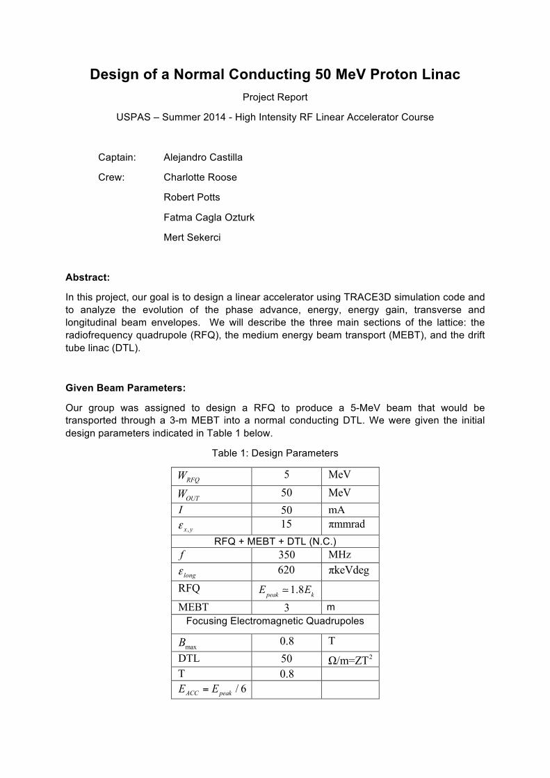
Design of a Normal Conducting 50 MeV Proton Linac Project Report
USPAS – Summer 2014 - High Intensity RF Linear Accelerator Course
Captain: Alejandro Castilla
Crew: Charlotte Roose
Robert Potts
Fatma Cagla Ozturk
Mert Sekerci
Abstract:
In this project, our goal is to design a linear accelerator using TRACE3D simulation code and to analyze the evolution of the phase advance, energy, energy gain, transverse and longitudinal beam envelopes. We will describe the three main sections of the lattice: the radiofrequency quadrupole (RFQ), the medium energy beam transport (MEBT), and the drift tube linac (DTL).
Given Beam Parameters:
Our group was assigned to design a RFQ to produce a 5-MeV beam that would be transported through a 3-m MEBT into a normal conducting DTL. We were given the initial design parameters indicated in Table 1 below.
Table 1: Design Parameters
RFQW 5 MeV
OUTW 50 MeV
I 50 mA
,x yε 15 πmmrad
RFQ + MEBT + DTL (N.C.) f 350 MHz
longε 620 πkeVdeg
RFQ Epeak 1.8Ek
MEBT 3 m Focusing Electromagnetic Quadrupoles
maxB 0.8 T
DTL 50 2Ω/m=ZT T 0.8
/ 6ACC peakE E=
Calculated Parameters:
From the given parameters, we determined the additional design parameters for the RFQ indicated in Table 2 below.
Table 2: Calculated Parameters
2o/ rV 10.5 2kV/mm
AV 60 kV kE 18.4 MV/m
Epeak 33 MV/m
λ 0.857 m A 0.6 -
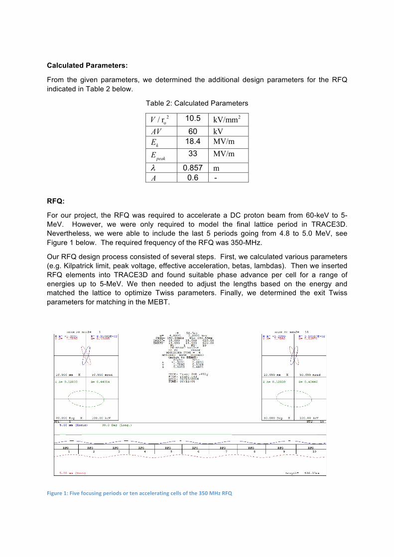
RFQ:
For our project, the RFQ was required to accelerate a DC proton beam from 60-keV to 5-MeV. However, we were only required to model the final lattice period in TRACE3D. Nevertheless, we were able to include the last 5 periods going from 4.8 to 5.0 MeV, see Figure 1 below. The required frequency of the RFQ was 350-MHz.
Our RFQ design process consisted of several steps. First, we calculated various parameters (e.g. Kilpatrick limit, peak voltage, effective acceleration, betas, lambdas). Then we inserted RFQ elements into TRACE3D and found suitable phase advance per cell for a range of energies up to 5-MeV. We then needed to adjust the lengths based on the energy and matched the lattice to optimize Twiss parameters. Finally, we determined the exit Twiss parameters for matching in the MEBT.
Figure 1: Five focusing periods or ten accelerating cells of the 350 MHz RFQ

DTL:
The requirement for the DTL was that it accepts a 50-mA 5-MeV proton beam from the MEBT and produces a 50-MeV proton beam. Additionally, we were specifically required to have frequency of 350-MHz, a transit time factor of 0.8, an effective impedance per unit length of 50 Ohms per meter, and a maximum magnetic field on the quadrupole’s pole tips of 0.8 Tesla. From the Kilpatrick criterion, we found our accelerating RF field to be 3-MV per meter. The recommended lattice was a FODO lattice with RF cavities located in each drift. We decided that the FODO lattice period would be equal to two times the RF period. This means that the RF cavities would be in the zero-mode.
Our DTL design process consisted of several steps. First, we systematically calculated various parameters with Excel (e.g. cavity lengths, voltages, quadrupole settings). Then we used Excel to create the repeating TRACE3D lattice elements. We then inserted the elements into TRACE3D and adjusted quadrupoles to optimize beam envelope. We matched the initial lattice period to optimize Twiss without space charge, and then with space charge. Finally, we determined the initial Twiss for matching in MEBT.
Shown in Figures 2 and 3 below are the final DTL lattice without and with space charge, respectively. Figures 4 and 5 depict the transverse and longitudinal phase advances in the DTL with and without current, respectively. As seen in Figure 4, the vertical phase advance still has problems. This was due in part to the limited time nature of our project. Figures 6 and 7 depict the energy and energy gains in the DTL with and without current, respectively. We were not able to collect information for various periods in the DTL for reasons explained in the Problems section of our report.
Figure 2: Final DTL lattice with no space charge.

Figure 4: Transverse (red and blue) and longitudinal (gray) phase advance in DTL for I=0mA.
0.0
10.0
20.0
30.0
40.0
50.0
60.0
70.0
80.0
90.0
0 10 20 30 40 50 60 70
Phase Ad
vance (deg)
FODO Cell Number
Phase Advance (I=0mA) Longitundinal Horizontal Ver<cal
Figure 3: Final DTL lattice with 50 mA of current.

Figure 5: Transverse (red and blue) and longitudinal (gray) phase advance in DTL for I=50mA.
Figure 6: Energy (blue) and energy gain (red) in the DTL for I=0mA.
0.0
10.0
20.0
30.0
40.0
50.0
60.0
70.0
80.0
90.0
0 10 20 30 40 50 60 70
Phase Ad
vance (deg)
FODO Cell Number
Phase Advance (I=50mA) Longitundinal Horizontal Ver<cal
0.0
0.2
0.4
0.6
0.8
1.0
1.2
0.0
10.0
20.0
30.0
40.0
50.0
60.0
0 10 20 30 40 50 60 70
Energy Gain (M
eV)
Total Ene
rgy (M
eV)
FODO Cell Number
Beam Energy (I=0mA) Energy Energy Gain

Figure 7: Energy (blue) and energy gain (red) in the DTL for I=50mA.
MEBT:
This section is designed for matching the transverse and longitudinal Twiss parameters at the exit of the RFQ to the entrance parameters of the DTL. The MEBT, shown in Figure 8 below, was restricted to 3 meters in length. The suggested lattice structure was three non-periodic FODO cells for transverse matching. Two RF gaps were chosen for longitudinal matching. We used “type 8” matching in TRACE3D to vary the quadrupole strengths while the longitudinal matching was made by iteratively matching by hand. We encountered difficulties on the transverse matching. These problems expanded on in the next sections. The final MEBT lattice is shown in Figure 9 below.
0.0
0.2
0.4
0.6
0.8
1.0
1.2
0.0
10.0
20.0
30.0
40.0
50.0
60.0
0 10 20 30 40 50 60 70
Energy Gain (M
eV)
Total Ene
rgy (M
eV)
FODO Cell Number
Beam Energy (I=50mA) Energy Energy Gain

Figure 8: Schematics of the RFQ and MEBT sections. Twiss parameters for the MEBT are taken from the RFQ.
Figure 9: Diagram of the full accelerator, including the RFQ, MEBT and DTL, showing the Twiss parameters at the end of the MEBT.
Problems:
The first problem that we encountered was with matching the MEBT. TRACE3D failed to match to Twiss parameters from DTL despite having sufficient matching parameters and matching iterations. We tried to use strength of the six quadrupoles in the MEBT to match the Twiss parameters and TRACE3D refused to utilize final two quadrupoles. While the matching algorithm stated that it had successfully matched the Twiss parameters, they were in fact not the set goal parameters.

The second problem that we encountered was determining the phase advance from the initial lattice element to an Nth element. This can be clearly seen in Figures 10 and 11 below, which accounts for the missing data points in Figures 4, 5, 6, and 7. Figure 11 displays the same problem calculating Twiss parameters for the DTL as displayed in Figure 10 for the MEBT. It should be noted that in Figure 11 the RFQ and MEBT lattice elements were not included in the lattice file. Therefore, matching in the MEBT cannot be to blame for the problem. At the end of our project it was suggested that the lack of phase advance in certain cells could be due to an imaginary phase advance when calculated from the trace of the transfer matrix. Due to the limited time frame of our project, we were not able to investigate this further.
Figure 10: Demonstrates TRACE3D's inability to display the Twiss parameters at various locations within the MEBT.
Figure 11: Demonstrates TRACE3D's inability to display the Twiss parameters at various locations within the DTL.
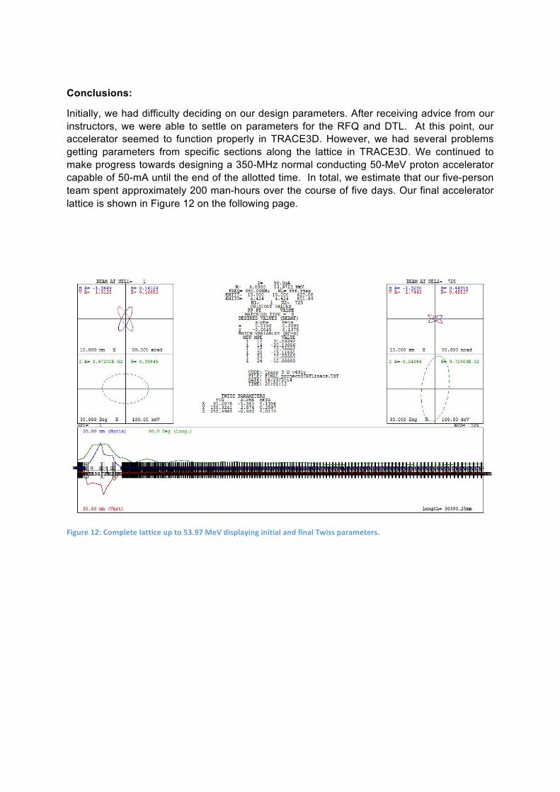
Conclusions:
Initially, we had difficulty deciding on our design parameters. After receiving advice from our instructors, we were able to settle on parameters for the RFQ and DTL. At this point, our accelerator seemed to function properly in TRACE3D. However, we had several problems getting parameters from specific sections along the lattice in TRACE3D. We continued to make progress towards designing a 350-MHz normal conducting 50-MeV proton accelerator capable of 50-mA until the end of the allotted time. In total, we estimate that our five-person team spent approximately 200 man-hours over the course of five days. Our final accelerator lattice is shown in Figure 12 on the following page.
Figure 12: Complete lattice up to 53.97 MeV displaying initial and final Twiss parameters.