Design of a long span Belfast truss using UK home-grown...
11
6th European Conference on Computational Mechanics (ECCM 6) 7th European Conference on Computational Fluid Dynamics (ECFD 7) 11 – 15 June 2018, Glasgow, UK Design of a long span Belfast truss using UK home-grown timber (ECCM –ECFD 2018 Conference) D. Johnstone¹, R. Hairstans ² and *A. Livingstone³ 1 Edinburgh Napier University, 10 Colinton Rd, Edinburgh EH10 5DT, [email protected] www.napier.ac.uk 2 Edinburgh Napier University, Unit 1, 7 Hills Business Park, Bankhead Crossway South, Edinburgh EH11 4EP, [email protected] www.napier.ac.uk 3 Edinburgh Napier University, Unit 1, 7 Hills Business Park, Bankhead Crossway South, Edinburgh EH11 4EP, [email protected] www.napier.ac.uk KEY WORDS: LONG SPAN TIMBER TRUSS, TIMBER CONNECTION CALCULATION SOFTWARE. 1 INTRODUCTION Industry partners of Edinburgh Napier University presented the desire for a long span timber roof system capable of delivering a clear span of 30m for industrial building projects, utilising UK Home-grown British spruce (WPCS). The Belfast truss design was identified for historical and aesthetic reasons, Figure 1. Design of the members and the connections were investigated. We found that although home-grown timber is often perceived as being inferior to imported timber it can have greater density, which is important in the design of timber connections. This research investigates the advantages of designing this structural roofing system using the recently defined for market bespoke strength class C16+, which with greater characteristic strength and density values, better fits the properties of UK grown spruce. Figure 1 Belfast truss design
Transcript of Design of a long span Belfast truss using UK home-grown...

6th European Conference on Computational Mechanics (ECCM 6)
7th European Conference on Computational Fluid Dynamics (ECFD 7)
11 – 15 June 2018, Glasgow, UK
Design of a long span Belfast truss using UK home-grown timber
(ECCM –ECFD 2018 Conference)
D. Johnstone¹, R. Hairstans² and *A. Livingstone³
1 Edinburgh Napier University, 10 Colinton Rd, Edinburgh EH10 5DT, [email protected]
www.napier.ac.uk
2 Edinburgh Napier University, Unit 1, 7 Hills Business Park, Bankhead Crossway South,
Edinburgh EH11 4EP, [email protected] www.napier.ac.uk 3 Edinburgh Napier University, Unit 1, 7 Hills Business Park, Bankhead Crossway South,
Edinburgh EH11 4EP, [email protected] www.napier.ac.uk
KEY WORDS: LONG SPAN TIMBER TRUSS, TIMBER CONNECTION
CALCULATION SOFTWARE.
1 INTRODUCTION
Industry partners of Edinburgh Napier University presented the desire for a long span
timber roof system capable of delivering a clear span of 30m for industrial building projects,
utilising UK Home-grown British spruce (WPCS). The Belfast truss design was identified for
historical and aesthetic reasons, Figure 1.
Design of the members and the connections were investigated. We found that although
home-grown timber is often perceived as being inferior to imported timber it can have greater
density, which is important in the design of timber connections. This research investigates the
advantages of designing this structural roofing system using the recently defined for market
bespoke strength class C16+, which with greater characteristic strength and density values,
better fits the properties of UK grown spruce.
Figure 1 Belfast truss design
D. Johnstone, R. Hairstans and A. Livingstone.
2
2 UK HOME-GROWN TIMBER
At present, roughly 53 million cubic metres of raw wood material is used in the UK each
year; 81% of that is imported timber [1, 2]. In 2014 the UK was the third highest importer of
timber products in the world, behind China and Japan. 13% of the land area in the UK is
covered by forest. However the European average is 38%, so the UK is still behind its
neighbours. This UK percentage of forest cover was as low as 5% at the turn of the 20th
century, so the UK timber industry is making progress (information from Forestry
Commission website [3]).
38% of sawn timber and 52% of wood panels used in the UK are from home-grown
sources, and it is predicted that the production of timber in the UK is to increase by 50% by
2025 [1]. As the UK timber industry increases, we must look to rely less on imported timber
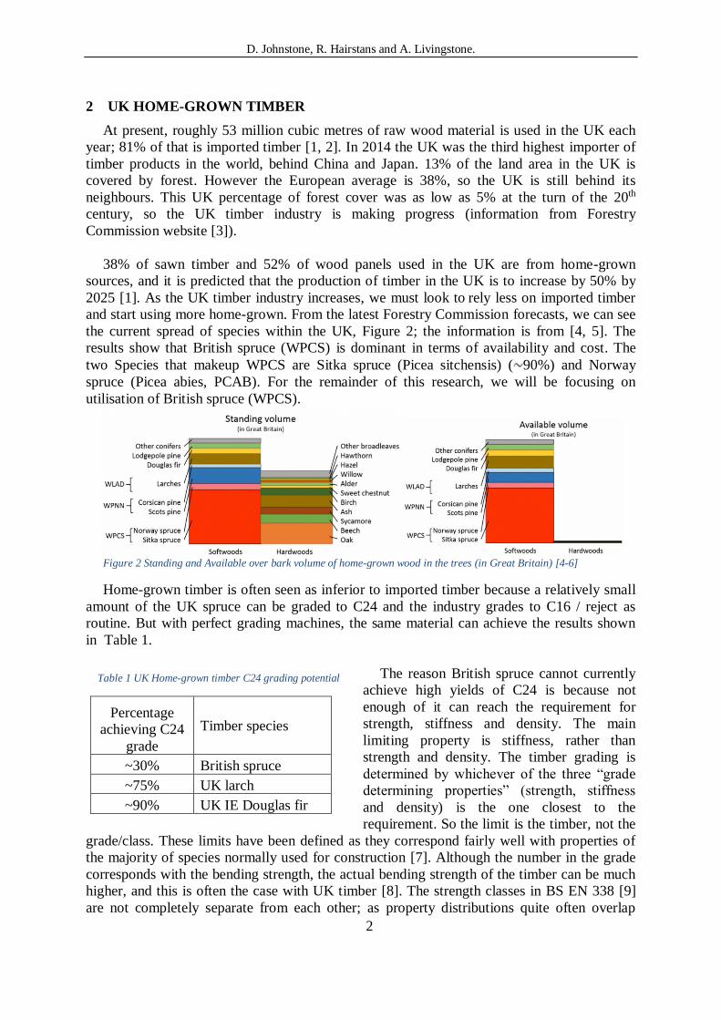
and start using more home-grown. From the latest Forestry Commission forecasts, we can see
the current spread of species within the UK, Figure 2; the information is from [4, 5]. The
results show that British spruce (WPCS) is dominant in terms of availability and cost. The
two Species that makeup WPCS are Sitka spruce (Picea sitchensis) ( 90%) and Norway
spruce (Picea abies, PCAB). For the remainder of this research, we will be focusing on
utilisation of British spruce (WPCS).
Figure 2 Standing and Available over bark volume of home-grown wood in the trees (in Great Britain) [4-6]
Home-grown timber is often seen as inferior to imported timber because a relatively small
amount of the UK spruce can be graded to C24 and the industry grades to C16 / reject as
routine. But with perfect grading machines, the same material can achieve the results shown
in Table 1.
The reason British spruce cannot currently
achieve high yields of C24 is because not
enough of it can reach the requirement for
strength, stiffness and density. The main
limiting property is stiffness, rather than
strength and density. The timber grading is
determined by whichever of the three “grade
determining properties” (strength, stiffness
and density) is the one closest to the
requirement. So the limit is the timber, not the
grade/class. These limits have been defined as they correspond fairly well with properties of
the majority of species normally used for construction [7]. Although the number in the grade
corresponds with the bending strength, the actual bending strength of the timber can be much
higher, and this is often the case with UK timber [8]. The strength classes in BS EN 338 [9]
are not completely separate from each other; as property distributions quite often overlap
Table 1 UK Home-grown timber C24 grading potential
Percentage
achieving C24
grade
Timber species
~30% British spruce
~75% UK larch
~90% UK IE Douglas fir
D. Johnstone, R. Hairstans and A. Livingstone.
3
between classes [7]. UK timber is generally said to grow too quickly, meaning that it has a
low density. However, studies at Edinburgh Napier University on one of the most popular UK
timbers, Sitka spruce, have shown that the density is the least limiting factor of the timber. It
is correct that it achieves saw log size with a short rotation; the drawback to this is not low
density but low stiffness due to the large ratio of juvenile wood [8].
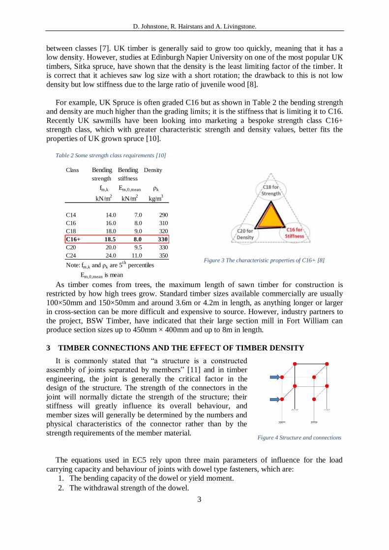
For example, UK Spruce is often graded C16 but as shown in Table 2 the bending strength
and density are much higher than the grading limits; it is the stiffness that is limiting it to C16.
Recently UK sawmills have been looking into marketing a bespoke strength class C16+
strength class, which with greater characteristic strength and density values, better fits the
properties of UK grown spruce [10].
Table 2 Some strength class requirements [10]
Class Bending Bending Density
strength stiffness
fm,k Em,0,mean ρk
kN/m2
kN/m2
kg/m3
C14 14.0 7.0 290
C16 16.0 8.0 310
C18 18.0 9.0 320
C16+ 18.5 8.0 330
C20 20.0 9.5 330
C24 24.0 11.0 350
Note: fm,k and ρk are 5th
percentiles
Em,0,mean is mean
Figure 3 The characteristic properties of C16+ [8]
As timber comes from trees, the maximum length of sawn timber for construction is
restricted by how high trees grow. Standard timber sizes available commercially are usually
100×50mm and 150×50mm and around 3.6m or 4.2m in length, as anything longer or larger
in cross-section can be more difficult and expensive to source. However, industry partners to
the project, BSW Timber, have indicated that their large section mill in Fort William can
produce section sizes up to 450mm × 400mm and up to 8m in length.
3 TIMBER CONNECTIONS AND THE EFFECT OF TIMBER DENSITY
It is commonly stated that “a structure is a constructed
assembly of joints separated by members” [11] and in timber
engineering, the joint is generally the critical factor in the
design of the structure. The strength of the connectors in the
joint will normally dictate the strength of the structure; their
stiffness will greatly influence its overall behaviour, and
member sizes will generally be determined by the numbers and
physical characteristics of the connector rather than by the
strength requirements of the member material.
The equations used in EC5 rely upon three main parameters of influence for the load
carrying capacity and behaviour of joints with dowel type fasteners, which are:
1. The bending capacity of the dowel or yield moment.
2. The withdrawal strength of the dowel.
Figure 4 Structure and connections

D. Johnstone, R. Hairstans and A. Livingstone.
4
3. The embedding strength of the timber or wood-based material.
Note: the timber density is the only timber property that is used in the calculation of lateral
load-carrying capacity.
Bending capacity or yield moment is
theoretically the maximum bending moment
that the dowel type fastener can resist before
going into a plastic deformation. Figure 5
shows a metal dowel connection that has
been tested into plastic deformation. The
possible strength increase due to the plastic
deformation is disregarded.
Characteristic withdrawal capacity within EC5 for nails comes from the minimum of the
point-side axle withdrawal and the head-side pull-through. Once the characteristic withdrawal
strengths are identified, either from the manufacturer’s test data
or from the EC5 equations, you may still be required
to multiply by a reduction factor depending upon the
penetration depth.
The embedment strength of the timber, or wood-based
product, fh, is the average compressive strength at
maximum load under the action of a stiff straight dowel.
According to BS EN 383 [12], see Figure 6.
Where:
is maximum load of the test, or
load at which a 5mm deformation occurred
is the fastener diameter
is the thickness of the timber
It’s been reported that from experimental tests, the influence factors for the embedment
strength of timber are [13, 14]:
• Density: embedment strength increases in a linear manner with respect to timber
density.
• Moisture content: as this increases the bending strength decreases, and this is
independent of timber species and dowel diameter.
• Diameter of the fixing or the predrilled hole: the embedment strength decreases with
increasing fastener diameter.
• Reinforcement of timber perpendicular to grain: for example, installing self-tapping
wood screws either side of a bolted connection will increase embedment strength
within that timber member.
• Friction between the fixing and timber will increase embedment strength.
The embedment strength calculation method within EC5 is as follows: For connections in
timber and LVL using bolts up to 30mm diameter.
Figure 5 Metal dowel shear test
Figure 6 Embedment test

D. Johnstone, R. Hairstans and A. Livingstone.
5
EC5 eq. (8.31)
EC5 eq. (8.32)
Where:
EC5 eq. (8.33)
and:
is the characteristic embedment strength parallel to grain, in N/mm2
is the characteristic density of the timber in kg/m3,
is the angle of the load to the grain
is the diameter of the bolt in mm
Figure 7 shows the increase in lateral shear resistance as density increases for a standard
M6 bolt acting in single shear for all 6 of the failure modes.
The calculation approach used within EC5 is based upon Johansen’s general theory [15,
16], and predicts the method of failure for the timber-to-timber and steel-to-timber
connections using dowel type fixings. This calculates each possible failure mode in turn and
so identifies the failure mode with the lowest resistance. The general format for these
equations can be summarised as: the result from the Johansen’s yield load, multiplied by any
effect from friction, plus the rope effect. See Figure 8.
There are two types of friction effect that can arise between the two timber members in a
connection. The first will develop if the members are in direct contact when assembled; this
friction will be eliminated either if there is no direct contact on assembly or if there is
shrinkage of the timber or wood products in
service. As a result of this it is
conservatively not considered in EC5. The
other will arise when the fasteners yield,
pulling the members together as the
fasteners deform (see Figure 9). This type of
friction will always arise in failure modes
that include yielding of the fasteners,
relating to such modes.
Figure 7 Density effects on resistance of a fastener Figure 8 Single shear - failure modes and equations
Figure 9 Dowel in single shear, fastener fully yields
D. Johnstone, R. Hairstans and A. Livingstone.
6
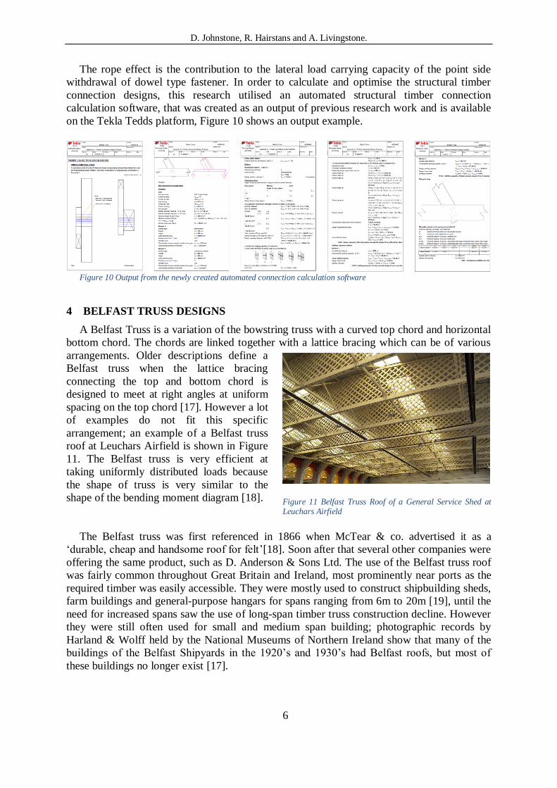
The rope effect is the contribution to the lateral load carrying capacity of the point side
withdrawal of dowel type fastener. In order to calculate and optimise the structural timber
connection designs, this research utilised an automated structural timber connection
calculation software, that was created as an output of previous research work and is available
on the Tekla Tedds platform, Figure 10 shows an output example.
Figure 10 Output from the newly created automated connection calculation software
4 BELFAST TRUSS DESIGNS
A Belfast Truss is a variation of the bowstring truss with a curved top chord and horizontal
bottom chord. The chords are linked together with a lattice bracing which can be of various
arrangements. Older descriptions define a
Belfast truss when the lattice bracing
connecting the top and bottom chord is
designed to meet at right angles at uniform
spacing on the top chord [17]. However a lot
of examples do not fit this specific
arrangement; an example of a Belfast truss
roof at Leuchars Airfield is shown in Figure
11. The Belfast truss is very efficient at
taking uniformly distributed loads because
the shape of truss is very similar to the
shape of the bending moment diagram [18].
The Belfast truss was first referenced in 1866 when McTear & co. advertised it as a
‘durable, cheap and handsome roof for felt’[18]. Soon after that several other companies were
offering the same product, such as D. Anderson & Sons Ltd. The use of the Belfast truss roof
was fairly common throughout Great Britain and Ireland, most prominently near ports as the
required timber was easily accessible. They were mostly used to construct shipbuilding sheds,
farm buildings and general-purpose hangars for spans ranging from 6m to 20m [19], until the
need for increased spans saw the use of long-span timber truss construction decline. However
they were still often used for small and medium span building; photographic records by
Harland & Wolff held by the National Museums of Northern Ireland show that many of the
buildings of the Belfast Shipyards in the 1920’s and 1930’s had Belfast roofs, but most of
these buildings no longer exist [17].
Figure 11 Belfast Truss Roof of a General Service Shed at Leuchars Airfield

D. Johnstone, R. Hairstans and A. Livingstone.
7
Figure 12 Different configurations of Belfast Truss
a)
b)
c)
d)
Different companies made different variations of the design with the same basic shape:
a) For the original McTear truss each
member of the lattice bracing, if projected
below the bottom chord, would meet at one
of two points about one-third of the span
below the end of the bottom chord as shown
in Figure 6.20a.
b) Figure 6.20b shows the Anderson design
of the truss where the bracing members are
positioned at 45° to the top chord and
uniformly spaced along
the top chord.
c) The modern Belfast truss (Figure 6.20c)
has the lattice bracing members at 45° to the
bottom chord and uniformly spaced along
the top chord.
d) The more conventional bowstring truss shown in Figure 6.20d has the lattice bracing
members at 45° to the bottom chord and uniformly spaced along the bottom chord. Gould et
al indicated that this is probably not justified as being a Belfast truss (Gould, Jennings, &
Montgomery, The Belfast Roof Truss,1992). However there are examples of this design being
called a Belfast truss.
Modern examples of Belfast truss roof designs Case studies.
In 2010 Wynstones School completed the construction of their new school hall (Figure
13), which incorporated the Belfast roof truss. Wynstones is a hands-on school, so with
the help of experienced carpenters, the pupils helped to construct nine 18.6m long
Belfast trusses. However, unsure about the all original timber design, the architects and
engineer on the project revised the design to include steelwork at either end of the
building ‘ensuring the timber frame won’t wrack in either direction’. From pictures, it
looks as though the Anderson design has been used for the Wynstones truss, it is also
noted that the ends of the truss are supported by haunched columns, which will provide
a moment resisting connection.
The sawmill building of Esgair Timber in Wales is constructed with a Belfast Truss
Roof. These trusses are 24m long and were designed by Barratt Associates, it can be
seen in Figure 14 that the lattice is spaced evenly along the bottom chord and the
angles are set from the bottom chord, which means they would be considered as
conventional bowstring trusses. It is also clear that the angle of the lattice bracing is not
of the traditional 45ᵒ; this could possibly provide a structural benefit to the truss, but at
this stage that is unclear. Discussions with Barratt Associates indicated that the success
of this building was as much to do with the skills of the carpenter as it was the
engineering design.
D. Johnstone, R. Hairstans and A. Livingstone.
8
Figure 13 Wynstone School, Belfast trusses (photo courtesy of David Gregory architects)
Figure 14 Belfast trusses at Esgair Timber (photo courtesy of Barratt Associates)
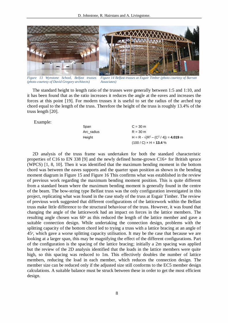
The standard height to length ratio of the trusses were generally between 1:5 and 1:10, and
it has been found that as the ratio increases it reduces the angle at the eaves and increases the
forces at this point [19]. For modern trusses it is useful to set the radius of the arched top
chord equal to the length of the truss. Therefore the height of the truss is roughly 13.4% of the
truss length [20].
Example: Span C = 30 m
Arc_radius R = 30 m
Height H = R - (R2 – (C2 / 4)) = 4.019 m
(100 / C) × H = 13.4 %
2D analysis of the truss frame was undertaken for both the standard characteristic
properties of C16 to EN 338 [9] and the newly defined home-grown C16+ for British spruce
(WPCS) [1, 8, 10]. Then it was identified that the maximum bending moment in the bottom
chord was between the eaves supports and the quarter span position as shown in the bending
moment diagram in Figure 15 and Figure 16 This confirms what was established in the review
of previous work regarding the maximum bending moment position. This is quite different
from a standard beam where the maximum bending moment is generally found in the centre
of the beam. The bow-string type Belfast truss was the only configuration investigated in this
project, replicating what was found in the case study of the truss at Esgair Timber. The review
of previous work suggested that different configurations of the latticework within the Belfast
truss make little difference to the structural behaviour of the truss. However, it was found that
changing the angle of the latticework had an impact on forces in the lattice members. The
resulting angle chosen was 60ᵒ as this reduced the length of the lattice member and gave a
suitable connection design. While undertaking the connection design, problems with the
splitting capacity of the bottom chord led to trying a truss with a lattice bracing at an angle of
45ᵒ, which gave a worse splitting capacity utilisation. It may be the case that because we are
looking at a larger span, this may be magnifying the effect of the different configurations. Part
of the configuration is the spacing of the lattice bracing; initially a 2m spacing was applied
but the review of the 2D analysis identified that the loads in the lattice members were quite
high, so this spacing was reduced to 1m. This effectively doubles the number of lattice
members, reducing the load in each member, which reduces the connection design. The
member size can be reduced only if the adjusted size still conforms to the EC5 member design
calculations. A suitable balance must be struck between these in order to get the most efficient
design.
D. Johnstone, R. Hairstans and A. Livingstone.
9
Figure 15 Bending moment example diagram
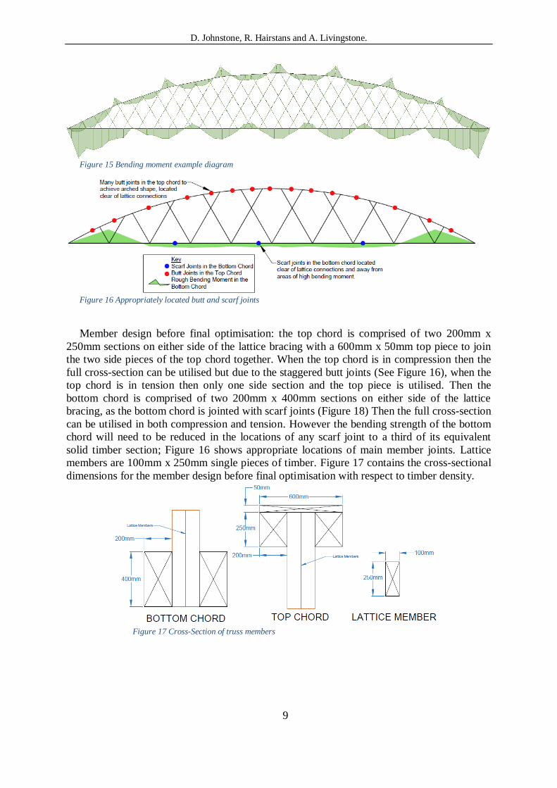
Figure 16 Appropriately located butt and scarf joints
Member design before final optimisation: the top chord is comprised of two 200mm x
250mm sections on either side of the lattice bracing with a 600mm x 50mm top piece to join
the two side pieces of the top chord together. When the top chord is in compression then the
full cross-section can be utilised but due to the staggered butt joints (See Figure 16), when the
top chord is in tension then only one side section and the top piece is utilised. Then the
bottom chord is comprised of two 200mm x 400mm sections on either side of the lattice
bracing, as the bottom chord is jointed with scarf joints (Figure 18) Then the full cross-section
can be utilised in both compression and tension. However the bending strength of the bottom
chord will need to be reduced in the locations of any scarf joint to a third of its equivalent
solid timber section; Figure 16 shows appropriate locations of main member joints. Lattice
members are 100mm x 250mm single pieces of timber. Figure 17 contains the cross-sectional
dimensions for the member design before final optimisation with respect to timber density.
Figure 17 Cross-Section of truss members

D. Johnstone, R. Hairstans and A. Livingstone.
10
Figure 18 Plan view of bottom chord, Scarf joint
5 CONCLUSIONS
Home-grown timber is often perceived as inferior to its imported equivalent but from the
results of this research, it has been demonstrated that home-grown timber can satisfy all the
Eurocode 5 structural checks for this Belfast truss design. When designing the connection, the
only timber property that the calculation takes into account is the density of the timber. The
new created C16+ grade of UK home-grown timber has a greater density than that of standard
graded C16.
Most C16 timber on the UK market is home-grown, but when designing this Belfast truss
example, using the density properties of the C16+ in comparison to standard C16, we observe
that the calculated minimum size of the timber members and the fixings can be reduced. For
illustration: The calculated size of the bottom chord timbers and the size and number of bolts
in the connection were able to be reduced for the C16+ design, see Table 1 and Table 3. But
when calculating for the standard C16 grade, we find failure in shear capacity for this reduced
design. This proves that utilising the greater density characteristics of the C16+ graded home-
grown timber can provide stronger connections with fewer fasteners, thus allowing section
sizes of the members to be reduced.
Table 3 Connection Design for C16 and C16+ timber members
Density Shear Splitting
ρk Capacity Capacity
Timber kg/m3 Utilisation Utilisation Connection
C16 310 0.843 0.809 9 no. M18 bolts, 400x200mm chord
C16+ 330 0.803 0.809 9 no. M18 bolts, 400x200mm chord
C16 310 1.037 0.998 6 no. M16 bolts, 350x150mm chord
C16+ 330 0.977 0.998 6 no. M16 bolts, 350x150mm chord
In conclusion, this example of a 30m clear span Belfast truss roof system using UK home-
grown timber graded to C16+ as opposed to standard C16 grade timber generated savings of:
• Timber section dimensions savings of 34.4%
• Metal fixings (bolts) savings of 47.3%
6 `FUTURE WORK
This project was ideal for demonstrating a computational timber connection calculation
software previously created within the research group. This software allowed for parametric
optimisation of the Beflast truss design. Continued work will focus on the digitization design
capacity for timber-rich houses, with a focus on home-grown timber.

D. Johnstone, R. Hairstans and A. Livingstone.
11
ACKNOWLEDGEMENTS
The authors would like to thank the industry partners BSW timber and Carbon Dynamic
for there participation in this project, and the Construction Scotland Innovation Center for
funding of the MSc project.
REFERENCES
1. Davies, I., Sustainable construction timber: sourcing and specifying local timber.
2016: Forestry Commission.
2. Forestry Commission, Statistics and Forestry Facts & Figures for 2017. 2018 [cited
2018 14/04/2018]; Forestry Statistics and Forestry Facts & Figures]. Available from:
https://www.forestry.gov.uk/forestry/infd-7aqdgc.
3. Forestry Commission website 2018 [cited 2018 14/04/2018]; Forestry Commission
website]. Available from: https://www.forestry.gov.uk/.
4. Brewer, A., 50-year forecast of softwood timber availability. 2014, Forestry
Commission, National Forest Inventory: http://www.forestry.gov.uk/inventory.
5. Brewer, A., 50-year forecast of Hardwood timber availability. 2014, Forestry
Commission, National Forest Inventory: http://www.forestry.gov.uk/inventory.
6. Ridley-Ellis, D., Grade in Britain. 2016: http://blogs.napier.ac.uk/cwst/grade-in-
britain/.
7. Ridley-Ellis, D., P. Stapel, and V. Baño, Strength grading of sawn timber in Europe:
an explanation for engineers and researchers. European Journal of Wood and Wood
Products, 2016. 74(3): p. 291-306.
8. Ridley-Ellis, D., S. Adams, and S. Lehneke, Thinking beyond the usual strength
grades-with examples of British spruce and larch. 2016.
9. BSi-BS-EN-338, BS EN 338:2016 Structural Timber - Strength Classes. 2016, BSI.
10. Ridley-Ellis, D., Derivation of GoldenEye-702 grading machine settings for British
Spruce. 2014, Report for CEN TC124/WG2/TG1: Edinburgh Napier University.
11. McLain, T.E. Connectors and fasteners: research needs and goals. in Wood
Engineering in the 21st Century: Research Needs and Goals. 1998. ASCE.
12. BSi-BS-EN-383, BS EN 383:2007 Timber Structures- Test methods _ Determination
of embedment strength and foundation values for dowel type fasteners. 2007.
13. Thelandersson, S. and H.J. Larsen, Timber engineering. 2003: John Wiley & Sons.
14. Rammer, D.R. and S.G. Winistorfer, Effect of moisture content on dowel-bearing
strength. Wood and fiber science, 2007. 33(1): p. 126-139.
15. Johansen, K., Forsøg med træ for bindelser (Experiments with wood for connections).
Bygningsstatiske meddelelser 1941. 2.
16. Johansen, K. Theory of timber connections. in International Association of Bridge and
Structural Engineering. 1949.
17. GOULD, M.H., A Historical Perspective on the Belfast Truss Roof Construction
History, 2001. 17(2001): p. 75 - 87.
18. Gould, M., A. Jennings, and R. Montgomery, Belfast roof truss. Structural Engineer,
1992. 70: p. 127-9.
19. Gilfillan, R. and S. Gilbert, The ‘Belfast’Roof Truss—Worth Conserving? Journal of
Architectural Conservation, 2003. 9(1): p. 45-57.
20. Gilbert, J.G.S., The Historic Belfast Timber Truss-A Way To Promote Sustainable
Roof Construction. 2002.