Design of a hydrostatic symmetric-pad bearing with … of a hydrostatic symmetric-pad bearing with...
36
Design of a hydrostatic symmetric-pad bearing with the membrane-type restrictor Professor: Shih-Chieh Lin Manufacturing and Production System Lab Dept. of Power Mechanical Engineering, National Tsing Hua University E-mail: [email protected] 1
Transcript of Design of a hydrostatic symmetric-pad bearing with … of a hydrostatic symmetric-pad bearing with...

Design of ahydrostatic symmetric-pad bearing with the membrane-type restrictor
Professor: Shih-Chieh Lin Manufacturing and Production System LabDept. of Power Mechanical Engineering, National Tsing Hua UniversityE-mail: [email protected]
1

Design of ahydrostatic symmetric-pad bearing with the membrane-type restrictor
2

Advantages can be characterized for hydrostatic bearings
Low friction (low speeds)
Infinite life (wear free)
Zero static friction (no stick slip)
High damping capacity (squeeze film)
High stiffness (membrane compensation)
3
Restrictor Rr
Single pad bearing
(Recess pressure p )
Pumping driver
(Supply pressure ps)
Most of compensation mechanisms for hydrostatic
bearing use a fluid resisting placed in series with
each bearing recess.
When the bearing gap close
> resistance goes up
> dropping the flow rate through the restrictor
> reducing the pressure drop across the restrictor > increasing the recess pressure
4
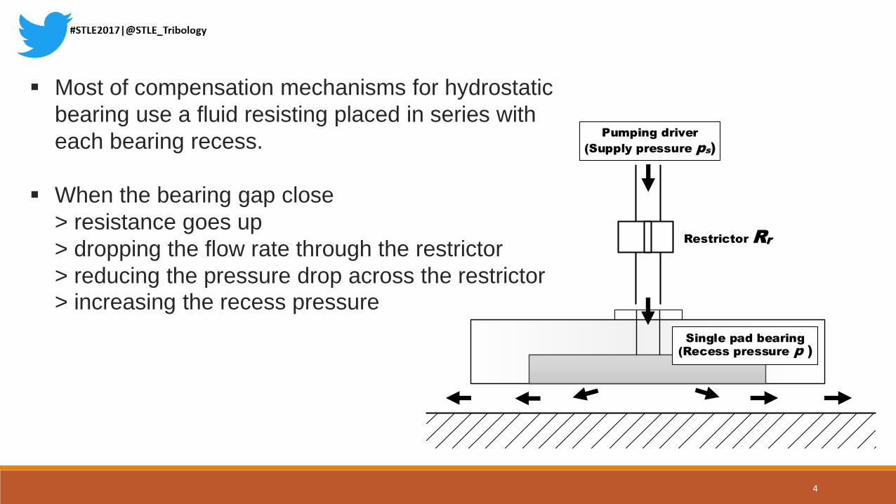
A membrane restrictor differs from many other variable restrictors in that the
flow is regulated by a metal diaphragm.
(also called diaphragm controlled restrictor, DCR)
l0
r1
Membrane
r2
Pumping driver
(Supply pressure ps)
Single pad bearing
(Recess pressure p )
x
r
Wz
h
Bearing
5

The flow rate model of the single-pad configuration
, s
r
p pQ p p p
R R p
Where R is the flow resistance of the bearing, which is inversely
proportional to the cube of the clearance h.
Restrictor Rr
Single pad bearing
(Recess pressure p )
Pumping driver
(Supply pressure ps)
*
3R R
h
6

For the hydrostatic bearing with infinite static stiffness, the flow
rate Q provided by the restrictor should be linearly proportional
to the recess pressure P. (i.e. R(h) will be a constant)
Restrictor Rr
Single pad bearing
(Recess pressure p )
Pumping driver
(Supply pressure ps)
h
Bearing resistance
Recess pressure
Restrictor
resistance
Pumping
driver p
RRr
ps
Atmosphere
7
Analytical consideration
for infinite stiffness
8
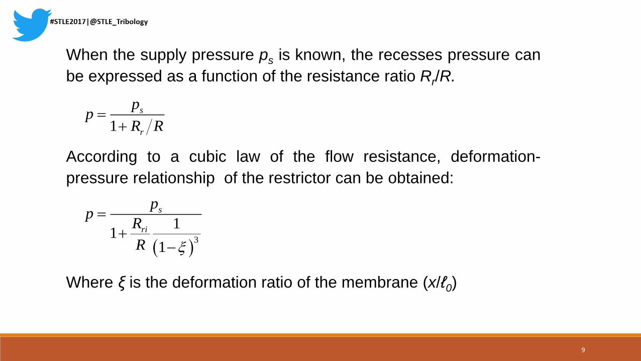
When the supply pressure ps is known, the recesses pressure can
be expressed as a function of the resistance ratio Rr/R.
1
s
r
pp
R R
According to a cubic law of the flow resistance, deformation-
pressure relationship of the restrictor can be obtained:
3
11
1
s
ri
pp
R
R
Where ξ is the deformation ratio of the membrane (x/ℓ0)
9
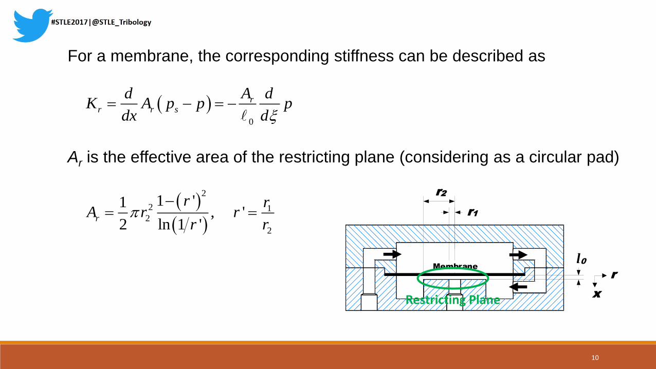
For a membrane, the corresponding stiffness can be described as
0
rr r s
Ad dK A p p p
dx d
Ar is the effective area of the restricting plane (considering as a circular pad)
2
2 12
2
1 '1, '
2 ln 1 'r
r rA r r
r r
l0
r1
Membrane
r2
Pumping driver
(Supply pressure ps)
Single pad bearing
(Recess pressure p )
x
r
Wz
h
Bearing
Restricting Plane
10

The corresponding stiffness of the ideal membrane for hydrostatic
bearing with infinite stiffness should be
2
2 *
, ,
0 0
13 1
1
s r s rr i r i
p A p AK K
2
3
0 0 0 1
1 6, lnri ri
ri
r
R R rR
R R r
Where λ is denoted as the design restriction ratio of the restrictor
11
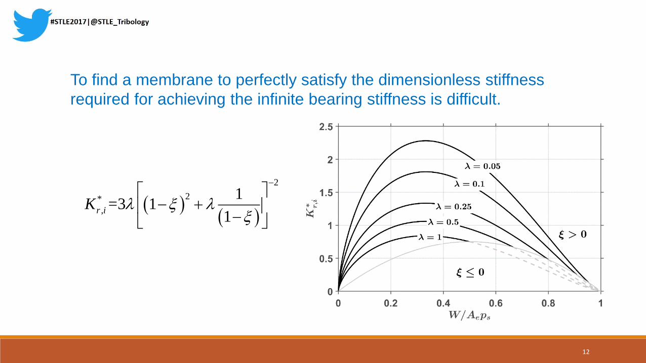
2
2*
,
1=3 1
1r iK
Where K*r,i is denoted as the dimensionless ideal corresponding
stiffness of the restrictor
To find a membrane to perfectly satisfy the dimensionless stiffness
required for achieving the infinite bearing stiffness is difficult.
12
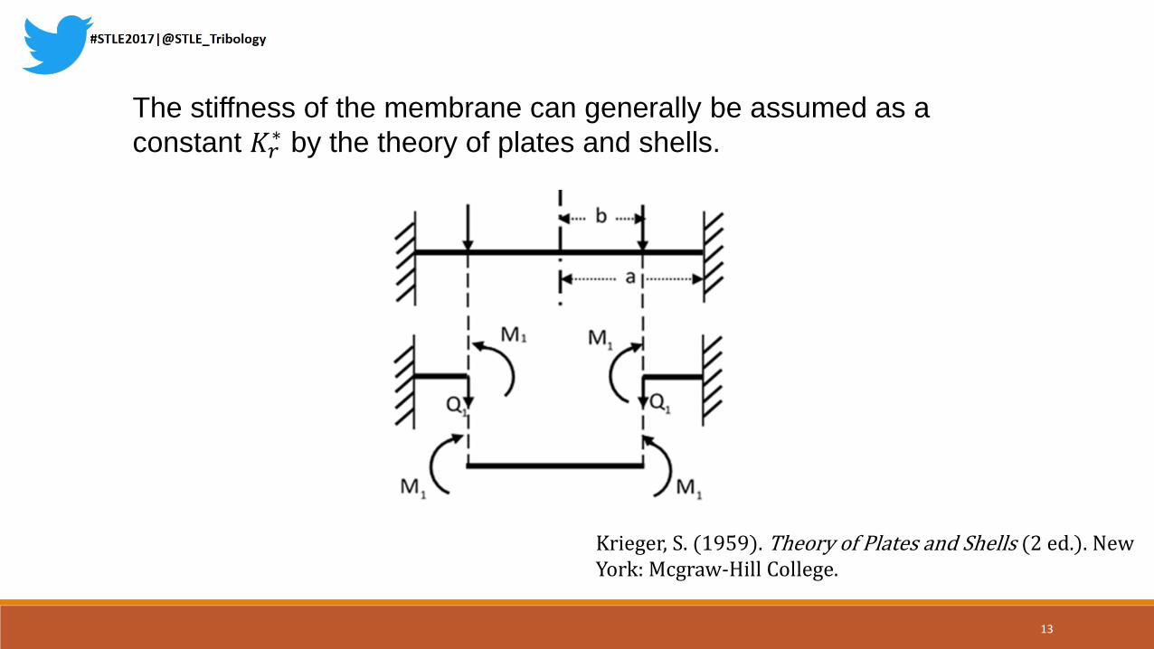
The stiffness of the membrane can generally be assumed as a
constant 𝐾𝑟∗ by the theory of plates and shells.
Krieger, S. (1959). Theory of Plates and Shells (2 ed.). New York: Mcgraw-Hill College.
13
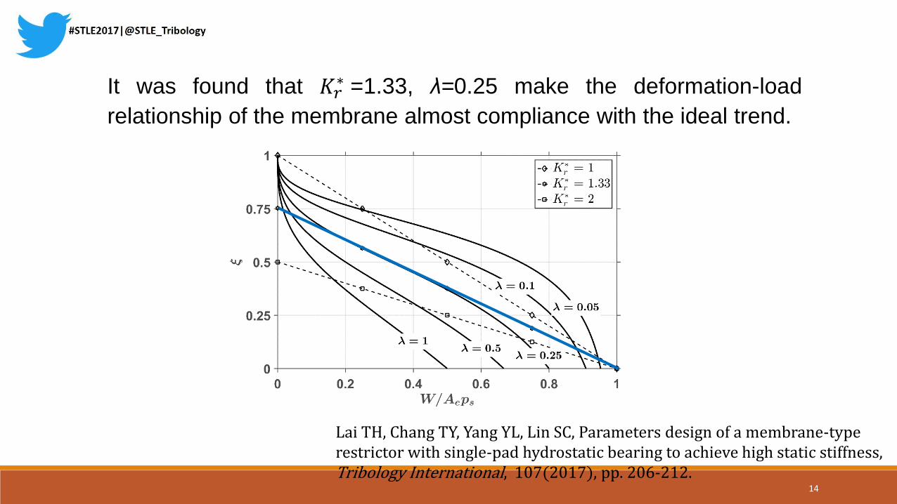
It was found that 𝐾𝑟∗ =1.33, λ=0.25 make the deformation-load
relationship of the membrane almost compliance with the ideal trend.
Lai TH, Chang TY, Yang YL, Lin SC, Parameters design of a membrane-type restrictor with single-pad hydrostatic bearing to achieve high static stiffness, Tribology International, 107(2017), pp. 206-212.
14

For the single-pad configuration, the clearance of the bearing can be
0
3 0*
0 0 0
1 1 11 1
1 1r
W WhW W
h W W K
and the stiffness of the bearing is
1
0
*
0 0 0
313
1 1 1r
W WWK
h W W K W W
15

Analytical Results and
Experiments
16
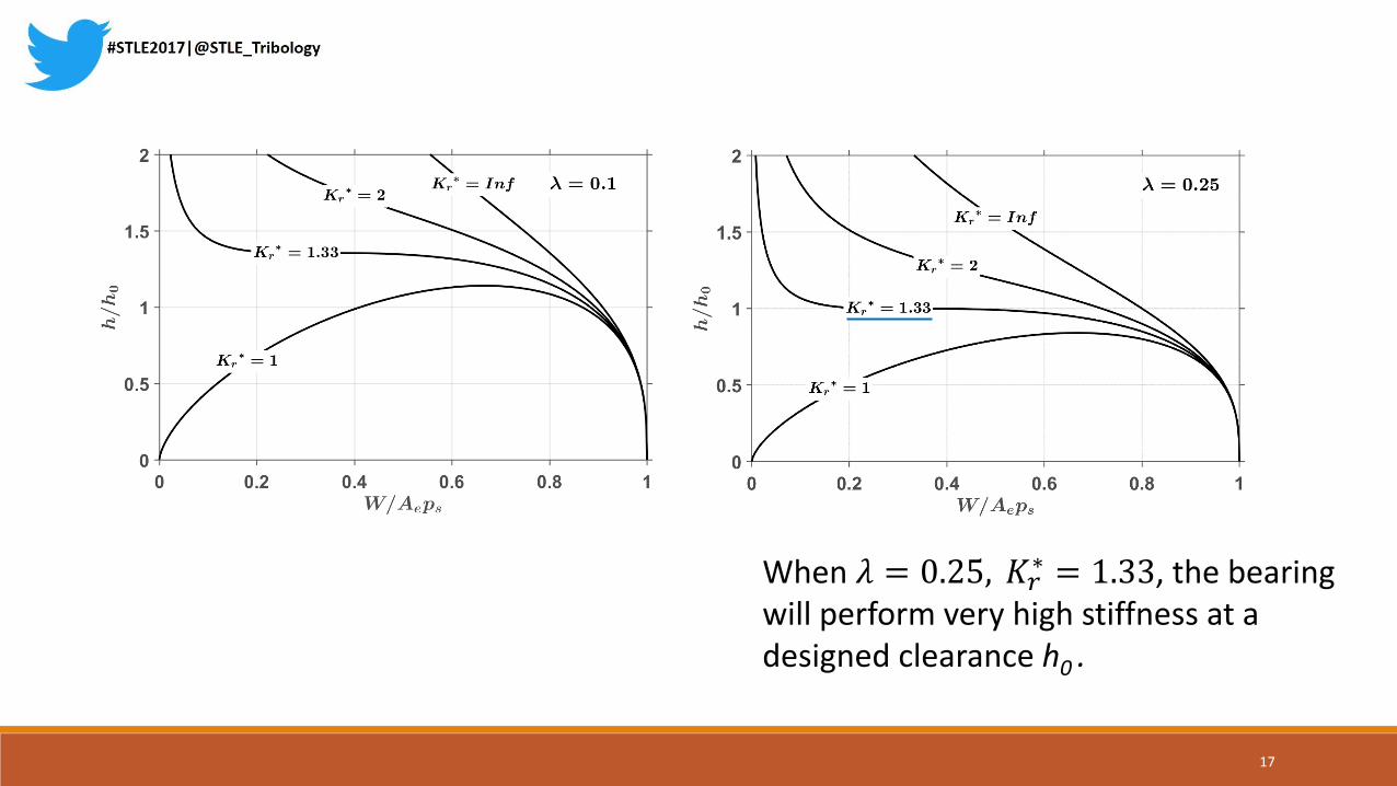
When 𝜆 = 0.25, 𝐾𝑟∗ = 1.33, the bearing
will perform very high stiffness at a designed clearance h0 .
17

Similar characteristics will observed with different 𝐾𝑟∗, and the
clearance ratio will decrease when λ is increased.
18
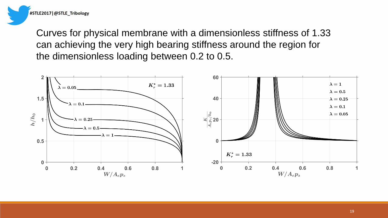
Curves for physical membrane with a dimensionless stiffness of 1.33
can achieving the very high bearing stiffness around the region for
the dimensionless loading between 0.2 to 0.5.
19

A very great stiffness could be obtained when 𝐾𝑟∗ = 1.33, but more
consideration is required to avoid the negative bearing stiffness.
(when 𝐾𝑟∗ < 1.33)
Negative stiffnessNegative stiffness
In the case 𝐾𝑟∗ = 1.0, the bearing will function with the negative
stiffness within the load range 𝑊 𝐴𝑒𝑝𝑠 = 0~0.67
20

Pressure sensor signal
conditioning
Matlab Data
acquisition devices
Pumping driver
Bypass
Bearing fluidsupply tank/
recovery tank
Hydrostatic linear bearing system
Heater
Acc.Particularfiliter(s)
Strainer
Flowmeter
Pressuresensor P1
Pressuresensor P2
Pressuresensor P0
Displacement sensor
signal conditioningEddycurrentsensor
PressureRegulator
Experiment system diagram
P2
P1
21

Parameters used in the experiment
Supply pressure ps 2.0 Bar
Reference pressure ratio β 0.5
Lubricant Viscosity η 0.041 PaSec
Diameters of restrictor r1, r2, r3 6, 10, 15 mm
Designed clearance of restrictor ℓ0 32 μm
Young’s modulus of membrane E 210 GPa
Poisson ratio of membrane v 0.3
Thickness of membrane t 0.5 mm
Applied load W 27, 36, 45, 54, 63, 72 Kg
Size of bearing pad B,C 80,200 mm
Radius of the inner fillet of bearing pad ri 5 mm
Width of the land of bearing pad ω 30 mm
Reference clearance of bearing pad h0 20 μm
0
Chang TY, Yang YL, Liu FR, Lin SC. Analysis on Parameters and Design of Membrane-type Restrictor.Proc of the Int Conf on Engineering and Natural Science - Summer Session; Kyoto; 2016; p.104-115
22
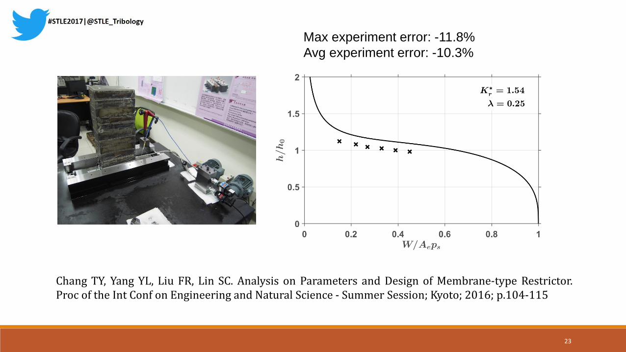
Max experiment error: -11.8%
Avg experiment error: -10.3%
Chang TY, Yang YL, Liu FR, Lin SC. Analysis on Parameters and Design of Membrane-type Restrictor.Proc of the Int Conf on Engineering and Natural Science - Summer Session; Kyoto; 2016; p.104-115
23
Symmetric-pad bearing
with the membrane-type restrictor
24
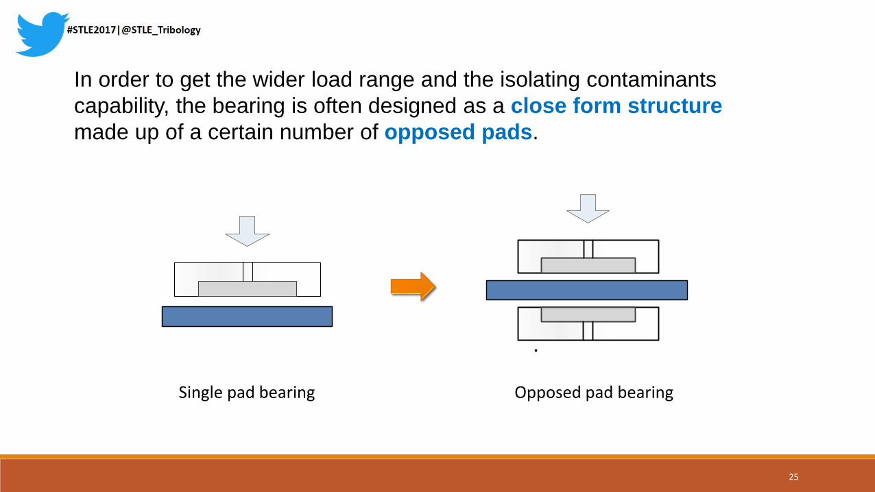
In order to get the wider load range and the isolating contaminants
capability, the bearing is often designed as a close form structure
made up of a certain number of opposed pads.
Single pad bearing Opposed pad bearing
25
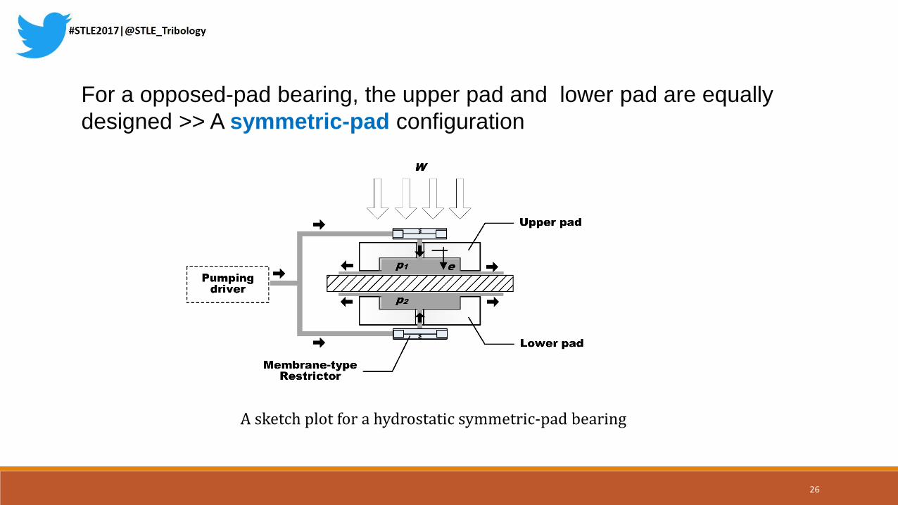
For a opposed-pad bearing, the upper pad and lower pad are equally
designed >> A symmetric-pad configuration
A sketch plot for a hydrostatic symmetric-pad bearing
26
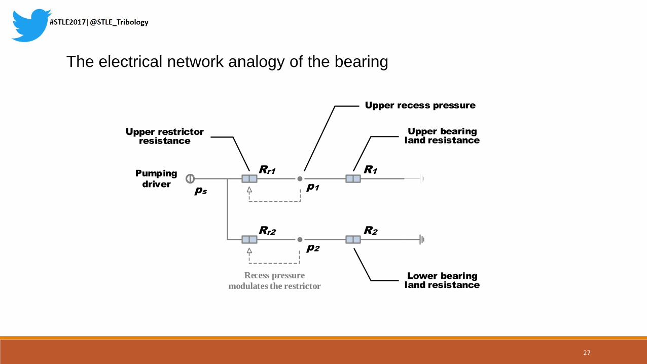
The electrical network analogy of the bearing
Upper bearing
land resistance
Upper recess pressure
Upper restrictor
resistance
Pumping
driver
Recess pressure
modulates the restrictor
p1
p2
R1
R2
Rr1
Rr2
ps
Lower bearing
land resistance
27

Analytical Results and
Discussions
28

Designation Values
𝐾𝑟1∗ = 𝐾𝑟2
∗ 1.33, 1.50, 2.00, 5.00, Inf
λ 0.05, 0.1, 0.25, 0.5, 1.0
ε 0 ~ 1.0
The effects of membrane stiffness on the symmetric-pad bearing
were evaluated with the parameter sets listed in the following table
<< Be equally designed
𝐾𝑟1∗ = 𝐾𝑟2
∗
29

Four obvious performance measures were adopt to give the grad of the bearing (ranged from 0.1~0.8 W/Aeps)
0.1 0.8
Havg : Average clearance
Hdev : Deviation of the clearance
Hdvr : Deviation ratio of the clearance
Hmin : Minimum clearance
W/Aeps
30
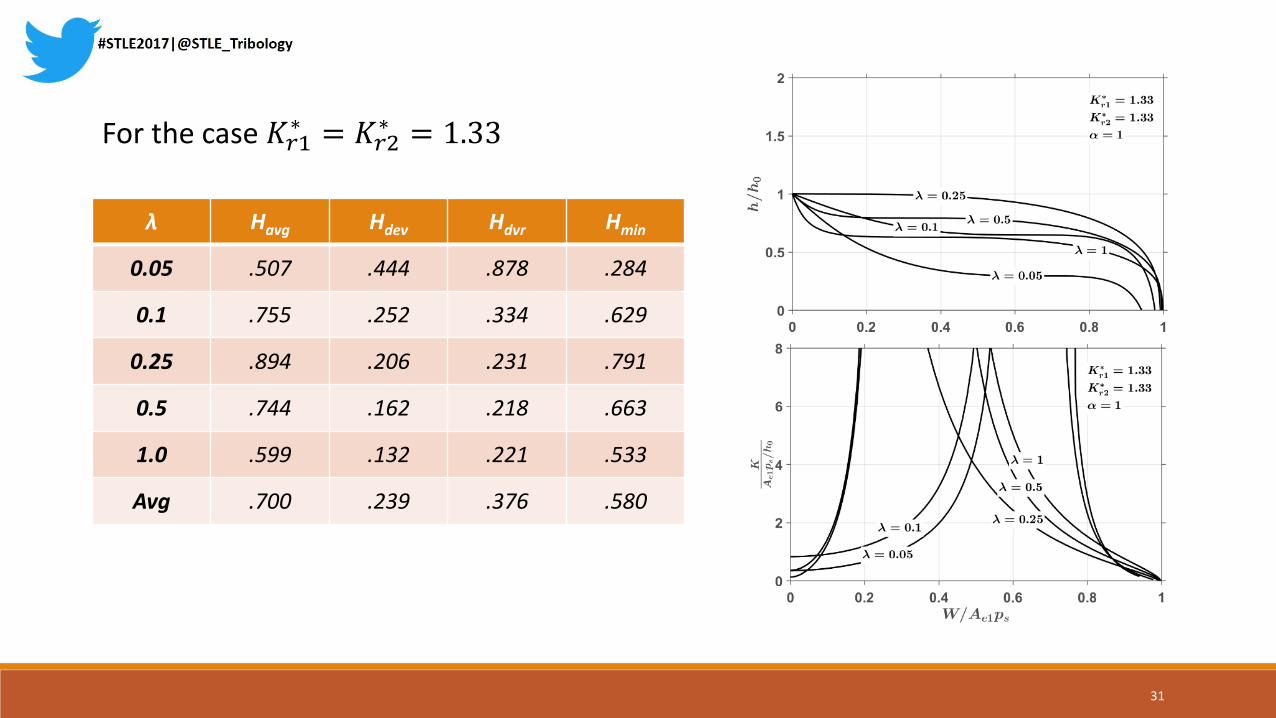
For the case 𝐾𝑟1∗ = 𝐾𝑟2
∗ = 1.33
λ Havg Hdev Hdvr Hmin
0.05 .507 .444 .878 .284
0.1 .755 .252 .334 .629
0.25 .894 .206 .231 .791
0.5 .744 .162 .218 .663
1.0 .599 .132 .221 .533
Avg .700 .239 .376 .580
31

1. The result shows that the membrane-type restrictor has greater static stiffness than traditional ones (i.e. capillary) not only for single-pad cases but also for symmetric-pad configurations.
2. It is recommend to choice 𝐾𝑟1∗ =𝐾𝑟2
∗ =1.33 and λ=0.25 for the membrane restrictor in a symmetric-pad bearing for light-load design.
3. The minimal deviation of the bearing clearance will appear when 𝐾𝑟1∗ =𝐾𝑟2
∗ =1.33 and λ=1.0 (i. e. 𝑅𝑟𝑖 = 𝑅0). The combination of the design parameters is recommend for heavy-load design.
Conclusions
32
4. The membrane restrictor will perform as a capillary restrictor when the stiffness of the membrane 𝐾𝑟
∗ > 5.0
5. It is similar to the single-pad case that the static stiffness of the opposed-pad bearing is inversely proportional to the nominal clearance of the bearing. The thinner nominal clearance is, the greater the stiffness and the smaller the power losses will be. (greater manufacturing accuracy will be required)
6. The bearing clearance will be maintained in most application range without any negative stiffness phenomena when both design parameter are properly chosen.
33

About our lab
34
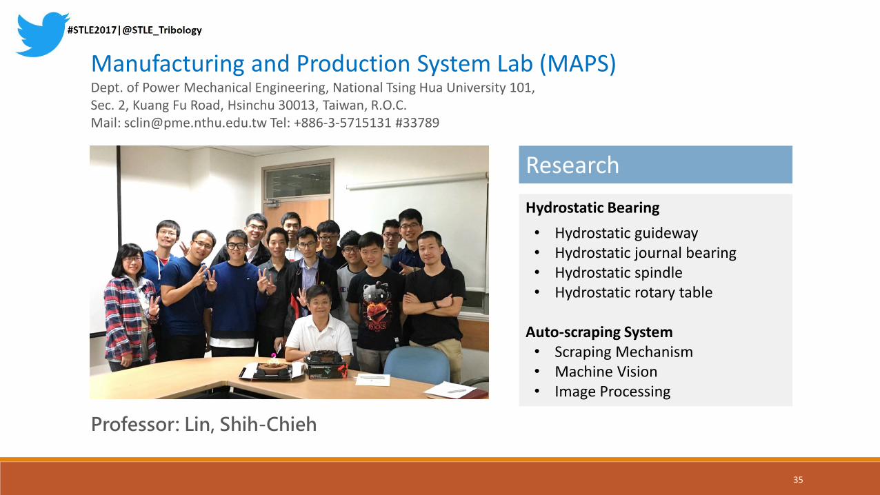
Professor: Lin, Shih-Chieh
Manufacturing and Production System Lab (MAPS)Dept. of Power Mechanical Engineering, National Tsing Hua University 101, Sec. 2, Kuang Fu Road, Hsinchu 30013, Taiwan, R.O.C. Mail: [email protected] Tel: +886-3-5715131 #33789
Research
Hydrostatic Bearing
• Hydrostatic guideway• Hydrostatic journal bearing• Hydrostatic spindle• Hydrostatic rotary table
Auto-scraping System• Scraping Mechanism• Machine Vision• Image Processing
35

Thanks for listening ~
36