Design of a Hopping Mechanism Using a Voice Coil …. 2. Physical structure and force-stroke...
6
Design of a Hopping Mechanism Using a Voice Coil Actuator: Linear Elastic Actuator in Parallel (LEAP) Zachary Batts, Joohyung Kim, and Katsu Yamane Abstract— Among legged robots, hopping and running robots are useful because they can traverse terrain at high speeds and are a benchmark platform for locomotion actuators; if an actu- ator can power a hopping robot, it can power a walking robot. We aim to create a hopping mechanism for a small-scale, one- legged, untethered hopping robot. A parallel-elastic actuator is an efficient way to do this, and enables the actuator to directly inject energy into the spring, but requires a high-speed, low- inertia actuator. Voice coil actuators are electrically-powered direct-drive translational motors that have very low moving inertia, low friction, can produce force at high speeds, and have a linear force output. These qualities make them ideal candidate motors for a linear elastic actuator in parallel (“LEAP”). Here, we derive an electromechanical model of the LEAP mechanism, develop a simple bang-bang hopping controller, and simulate hopping with a range of spring parameters to find an optimal spring stiffness that maximizes hopping height. We detail our implemented design, and characterize its performance through a series of experiments. We test our robot with different spring stiffnesses, and demonstrate hopping at a maximum steady- state of 3.5 cm ground-clearance (approx. 20% leg length). Our results suggest that the LEAP mechanism may serve the weight-bearing functions of a robot leg. I. INTRODUCTION Legged robots have been conceived and implemented since the 1970s [1], [2]. Hopping robots [3] are highly dy- namic mobile platforms that can be represented by reduced- dimensional models [4], which simplifies their control and simulation. However, hopping robots require high-speed, high force actuation due to the physical requirements of achieving non-trivial ground clearance. The first hopping robots were developed at the MIT/CMU Leg Laboratory [5], including a series of 2D and 3D hoppers. More recently, Boston Dynamics has continued this research and produced a quadruped robot, BigDog [6], which can walk and hop robustly using hydraulic actuators. Other researchers [7], [8] have achieved hopping motions with monopod, biped and quadruped robots using electrical motors. Although untethered hydraulically-actuated hopping robots [6], [9], [10] can often outperform their electrical counterparts, they cause safety concerns and have added design constraints. Hydraulic actuators in a robot system are powered by a compressor, which are relatively large, heavy, and must be placed on the body of the robot. Furthermore, compressors typically operate at high pressure, are often fueled by flammable liquids, and drive very large actuator forces. All of these issues pose safety hazards Z. Batts, J. Kim, and K. Yamane are with Disney Research, 4720 Forbes Ave., Lower Level, Suite 110, Pittsburgh, PA 15213, USA. {zachary.batts,joohyung.kim,kyamane}@disneyresearch.com Fig. 1. CAD model of the hopping mechanism. A prismatic joint is realized using two shaft-bearing pairs. Compression springs coil around each shaft and act in parallel to the voice coil. An incremental encoder measures the relative displacement (“stroke”) of the coil and body. to human operators, especially during legged locomotion where collisions (wanted and unwanted) are ubiquitous. Legged robots often employ series elastic actuators (SEA) to drive their joints [11], [12]. By introducing compliance between the actuator and the robot linkage, an SEA is capable of storing energy and absorbing impacts between the robot and the environment. On the other hand, parallel elastic actuators (PEA) can reduce power consumption and increase the net force or torque of the actuator during legged loco- motion [13], [14]. Despite these advantages, few prismatic (translational motion) PEAs have been implemented due to the difficulties in converting the rotary motion of an electric motor to linear movement, which can introduce unacceptable friction, hysteresis due to gearing backlash, and non-linear force output. A type of direct-drive linear motor, called a voice coil, may offer an alternative to a geared electric rotary motor. A voice coil is a prismatic electric actuator that has negligible friction, no gearing, and a linear force output [15]. Here, we develop a linear elastic actuator in parallel (“LEAP”), which places a voice coil actuator in parallel with a spring (Fig. 1) to drive a small scale hopping robot. We choose a parallel configuration to offload the force requirements of the mechanism to the spring, and allow the voice coil to inject energy directly into the spring. We first present an electromechanical model of the LEAP mecha- nism, develop a controller that maximizes energy injection,
-
Upload
phungthien -
Category
Documents
-
view
231 -
download
3
Transcript of Design of a Hopping Mechanism Using a Voice Coil …. 2. Physical structure and force-stroke...

Design of a Hopping Mechanism Using a Voice Coil Actuator:Linear Elastic Actuator in Parallel (LEAP)
Zachary Batts, Joohyung Kim, and Katsu Yamane
Abstract— Among legged robots, hopping and running robotsare useful because they can traverse terrain at high speeds andare a benchmark platform for locomotion actuators; if an actu-ator can power a hopping robot, it can power a walking robot.We aim to create a hopping mechanism for a small-scale, one-legged, untethered hopping robot. A parallel-elastic actuator isan efficient way to do this, and enables the actuator to directlyinject energy into the spring, but requires a high-speed, low-inertia actuator. Voice coil actuators are electrically-powereddirect-drive translational motors that have very low movinginertia, low friction, can produce force at high speeds, and havea linear force output. These qualities make them ideal candidatemotors for a linear elastic actuator in parallel (“LEAP”). Here,we derive an electromechanical model of the LEAP mechanism,develop a simple bang-bang hopping controller, and simulatehopping with a range of spring parameters to find an optimalspring stiffness that maximizes hopping height. We detail ourimplemented design, and characterize its performance througha series of experiments. We test our robot with different springstiffnesses, and demonstrate hopping at a maximum steady-state of 3.5 cm ground-clearance (approx. 20% leg length).Our results suggest that the LEAP mechanism may serve theweight-bearing functions of a robot leg.
I. INTRODUCTION
Legged robots have been conceived and implementedsince the 1970s [1], [2]. Hopping robots [3] are highly dy-namic mobile platforms that can be represented by reduced-dimensional models [4], which simplifies their control andsimulation. However, hopping robots require high-speed,high force actuation due to the physical requirements ofachieving non-trivial ground clearance. The first hoppingrobots were developed at the MIT/CMU Leg Laboratory [5],including a series of 2D and 3D hoppers. More recently,Boston Dynamics has continued this research and produceda quadruped robot, BigDog [6], which can walk and hoprobustly using hydraulic actuators. Other researchers [7], [8]have achieved hopping motions with monopod, biped andquadruped robots using electrical motors.
Although untethered hydraulically-actuated hoppingrobots [6], [9], [10] can often outperform their electricalcounterparts, they cause safety concerns and have addeddesign constraints. Hydraulic actuators in a robot systemare powered by a compressor, which are relatively large,heavy, and must be placed on the body of the robot.Furthermore, compressors typically operate at high pressure,are often fueled by flammable liquids, and drive very largeactuator forces. All of these issues pose safety hazards
Z. Batts, J. Kim, and K. Yamane are with Disney Research, 4720Forbes Ave., Lower Level, Suite 110, Pittsburgh, PA 15213, USA.zachary.batts,joohyung.kim,[email protected]
Fig. 1. CAD model of the hopping mechanism. A prismatic joint is realizedusing two shaft-bearing pairs. Compression springs coil around each shaftand act in parallel to the voice coil. An incremental encoder measures therelative displacement (“stroke”) of the coil and body.
to human operators, especially during legged locomotionwhere collisions (wanted and unwanted) are ubiquitous.
Legged robots often employ series elastic actuators (SEA)to drive their joints [11], [12]. By introducing compliancebetween the actuator and the robot linkage, an SEA iscapable of storing energy and absorbing impacts between therobot and the environment. On the other hand, parallel elasticactuators (PEA) can reduce power consumption and increasethe net force or torque of the actuator during legged loco-motion [13], [14]. Despite these advantages, few prismatic(translational motion) PEAs have been implemented due tothe difficulties in converting the rotary motion of an electricmotor to linear movement, which can introduce unacceptablefriction, hysteresis due to gearing backlash, and non-linearforce output. A type of direct-drive linear motor, called avoice coil, may offer an alternative to a geared electric rotarymotor. A voice coil is a prismatic electric actuator that hasnegligible friction, no gearing, and a linear force output [15].
Here, we develop a linear elastic actuator in parallel(“LEAP”), which places a voice coil actuator in parallelwith a spring (Fig. 1) to drive a small scale hopping robot.We choose a parallel configuration to offload the forcerequirements of the mechanism to the spring, and allow thevoice coil to inject energy directly into the spring. We firstpresent an electromechanical model of the LEAP mecha-nism, develop a controller that maximizes energy injection,

Fig. 2. Physical structure and force-stroke relationship of a voice coil. (a)Cross section of a cylindrical voice coil reveals an iron core that concentratesmagnetic flux across a coil. As current is passed through the coil, a forcedevelops between the iron core and coil along their mutual axis. (b) Force-stroke relation for our specific voice coil model [16], at constant currentand zero stroke velocity.
and simulate the hopper with a range of spring parameters(Sec. II). We then detail our physical implementation ofthe LEAP mechanism (Sec. III). Next, we investigate thebehavior of our physical system through a series of exper-iments (Sec. IV); we verify a linear relationship betweeninput current and output force, identify the stiction forceof our prismatic joint, and present hopping data for oursystem at several spring constants. Finally, we discuss ourexperimental results, summarize the paper, and pose futureresearch (Sec. V).
II. MODEL, CONTROLLER, AND SIMULATION
A. Circuit Model for Voice Coil Dynamics
A voice coil (Fig. 2–A) is an electric actuator that exertsforce along its axis that is proportional to the current passingthrough it. It consists of two components, the body andthe coil, that translate relative to each other along theirmutual axes, without making physical contact with eachother. The body consists of a permanent magnet and ironcore that concentrates magnetic flux radially through thecoil, perpendicular to its current flow. A magnetic Lorentzforce, F , is developed between the body and coil that isproportional to the current through the coil, I , the magneticflux density, number of windings, and length of conductor[17]. This relation can be condensed to
F = KfI, (1)
where Kf is the force constant that is dependent on therelative displacement of the body and coil, called the stroke(Fig. 2–B).
A voice coil circuit (Fig. 3–A) can be modeled as a singleloop with voltage source V , resistor R, inductor L, andvelocity-dependent electromotive force (back-EMF) elementKb in series. The back-EMF voltage drop is proportional to
Fig. 3. Electromechanical model diagrams. (a) Voice coil circuit comprisesa voltage supply V , back-EMF Kb, resistance R, and inductance L in series,with current I . (b) Two degree-of-freedom mechanical model includes torsomass m1 with height q1, voice coil with stroke q2 and force constant Kf ,parallel spring with elasticity k and damping b, foot mass m2, and gravityg.
the stroke velocity. The differential equation governing theelectrical dynamics is
V − IR− dI
dtL−Kb
dq2dt
= 0, (2)
where q2 is the stroke. Kb has the same dimensions as Kf
(in SI units, Kf = Kb). Note that the dynamics equationsof a voice coil are analogous to a DC rotary motor, exceptthat they describe translational motion. Assuming zero strokevelocity, the relation between current and voltage is firstorder in time, with RL time constant τ = L
R .
B. Mechanical Model for Parallel Elastic Actuator
Our mechanism comprises an elastic element in parallelwith a voice coil (Fig. 3–B) and serves the weight-bearingfunctions of a leg. Namely, it can produce forces greaterthan body weight, can support weight when turned off,can act compliantly or rigidly, and can store and dissipatemechanical energy. On its own, a voice coil could not achieveall of these functions. The parallel elastic element reducesthe force and power requirements of the voice coil, canstore energy, and adds passive compliance to the mechanism.We choose a parallel configuration such that the forces inthe elastic element and actuator are additive. Compared toa series-elastic actuator (SEA), a parallel-elastic actuator(PEA) can achieve larger forces and can inject energy intothe system during both compression and extension. Both ofthese qualities are desireable to maximize hopping height.A PEA can also be implemented in a shorter length thanan SEA, which means it can have less inertia as a swingleg, and is easier to include in a robot design. We employ avoice coil as our actuator because it has negligible internalfriction (the body and coil do not make physical contact), hasno gearing, has low moving inertia (a lightweight coil), andhas high force bandwidth. These traits mean it can generatenet positive work at high speeds and accelerations that aretypical during hopping, while passively adding little inertiaand friction to the mechanism.

TABLE ISIMULATION MODEL PARAMETERS AND INITIAL CONDITIONS
Parameter Value Units Parameter Value Unitsm1 1.145 kg R 10 Ωm2 0.313 kg L 3.2 mHg 9.81 m/s2 Kf 5 N/Akg 14300 N/m Kb 5 V/m/s
vmax 0.01 m/s Vmax 22.2 Vq1(t = 0) 0.1635 m l0 0.0635 mq2(t = 0) 0.0635 m max(q2) 0.0635 mmin(q2) 0 m qthresh2 0.0585 m
The equations of motion for our mechanical model can bederived as
m1q1 = k(l0 − q2)− bq2 +KfI −m1g (3)m2(q1 − q2) = k(q2 − l0) + bq2 −KfI −m2g − Fy, (4)
where m1 and m2 are the lump masses of the robot torsoand foot, respectively, g is the acceleration of gravity, k andb are the spring elastic and damping constants, respectively,l0 is the spring rest length, q1 and q2 are the generalizedcoordinates (torso height and voice coil stroke), and Fy isthe vertical ground reaction force,
Fy = −kgy(1− y
vmax
)[y
vmax< 1
][y < 0], (5)
where kg is the ground stiffness, y = q1 − q2 is the footheight, vmax > 0 is the maximum ground relaxation speed,and the [∗] operator evaluates to a binary 0 or 1. This non-linear ground reaction model captures the properties of aninelastic collision (vmax → 0 describes perfectly inelasticcollisions with infinite damping; vmax = ∞ describesperfectly elastic collisions) [18]. We use the same contactmodel to capture mechanical limit collisions at the maximumor minimum stroke (not shown in Equations (3) or (4)).
C. Simple Control Strategy Maximizes Actuator Work
To maximize hopping height, the voice coil should injectmaximal energy into the spring during one hopping cycle.To maximize actuator work, we use a simple bang-bang con-troller that commands zero voltage during flight, maximumnegative voltage during compression, and maximum positivevoltage during extension. We assume the mechanism is inflight if the stroke exceeds a threshold value q2 > qthresh2 .Similarly, we assume the foot is in contact with the groundif q2 ≤ qthresh2 , where there is non-zero spring deflection.Our controller commands voltage as
V =
0 if q2 > qthresh2
−Vmax else if q2 < 0
Vmax else if q2 ≥ 0
, (6)
where Vmax is the maximum supply voltage. We don’t pre-compress the spring during flight to avoid exceeding thepower limit of the voice coil. Since the RL time constant(τ = L
R ) for our voice coil is much smaller than the approxi-mate spring-mass hopping period (T ≈
√m1
k ), our controllerassumes that voltage, current, and force are proportional at
Fig. 4. Average hopping height was recorded for multiple simulationsof our system, across a range of spring stiffness and damping coefficients.Critical damping is calculated as b = 2
√km1.
any stroke velocity, and that commanding maximum voltageis equivalent to commanding maximum force.
We simulate our system continuously (the controller is as-sumed continuous) with a variable time-step solver (ode15s,relative error tolerance: 1e-4, absolute error tolerance 1e-5) using Matlab Simulink/SimMechanics/Simscape software.To determine an optimal spring stiffness that maximizeshopping height, we simulated our system with a range ofstiffnesses, assuming a range of damping coefficients (0%,5% and 10% critical damping). The simulation parametersand initial conditions given in Table I are equal to the mea-sured parameters of our physical implementation (Sec. III).The force-stroke dependence is given in Figure 2–B; weapproximate this relationship as a piecewise function with 10equally-spaced nodes. We simulate the system for 10 secondsfor each trial, with zero initial velocity, and 0.1m initial footheight. The resulting steady-state hopping heights (averageground clearance) are given in Figure 4.
III. PHYSICAL IMPLEMENTATION
Our physical implementation of the hopping mechanism(Fig. 1) centers around an off-the-shelf voice coil motor [16].Given an approximate desired mass, length, and nominalforce for our actuator, we surveyed multiple voice coilmanufacturers and selected a model roughly by maximizingwork density and stroke while minimizing price. The voicecoil parameters are given in Table I, and are the samein simulation and in hardware. The hopping mechanismconsists of a torso and a foot assembly, which translaterelative to each other via linear bearings and an aluminumshaft. Compression springs coil around each shaft, and actin parallel to the voice coil. An incremental encoder (4724counts per meter, before quadrature) measures the stroke ofthe voice coil. A rubber foot pad dampens collisions withthe ground. The coil housing, body housing, and codestrip

Fig. 5. Linear relation between voice coil force and sensor voltage.Slope and bias for the least-squares linear fit are m = 29.5, b = 0.16,respectively.
holder were manufactured on a 3D printer. The springs werepurchased from stock, and have stiffnesses that roughly spanthe range of our simulated results.
Since we aim to use our hopping mechanism on anuntethered robot, we implemented our controller using em-bedded electronics, and used lightweight (approx. 210 gtotal) Lithium-polymer batteries to power our logic circuitand voice coil driver. Our control circuit consists of amicrocontroller (Parallax Propeller P8X32A), a voice coilvoltage driver (Moticont 800 series), a current sensor (Alle-gro ACS712) to estimate voice coil force, and an ADC chip(Texas Instruments ADS1015) to read the current sensor. Alinear incremental optical encoder (US Digital EM1-0-120-N) and a rotary incremental optical encoder (US Digital E2-32-250-NE-H-D-B) give us full state estimation, and are readdirectly from the microcontroller. The sensor and controlloop run at 1 kHz, while data is output to a desktop computerat approximately 850 Hz (i.e. as fast as possible over serialconnection).
IV. EXPERIMENTS
We perform three experiments to identify system param-eters and validate our electromechanical model. First, wecalibrate our current sensor, ADC, and voice coil to verifya linear relationship between voice coil force and measuredcurrent. Second, we identify the breakaway stiction force ofour linear bearings using our horizontal experimental setupto ensure that it is small compared to spring and voice coilforce. Third, we test our hopping mechanism with differentspring stiffnesses and present the results. Through these testswe identify relevant system parameters and show that ouroriginal model captures the general behavior of our physicalsystem.
Fig. 6. CAD model of experimental setup. An encoder measures the heightof the hopping mechanism, which is constrained to a vertical rail. Mass canbe added to the system in measured quantities.
A. Force-Current Calibration
In the first experiment, we invert the mechanism such thatthe foot points upward and rigidly constrains the body hous-ing to a workbench, allowing the foot assembly to translatevertically with a single degree-of-freedom. We remove thesprings and add weights of varying mass to the foot assemblyto determine a force-current relationship for our voice coil.We run a PID position controller to drive the voice coil tomid-stroke, where we assume the force constant is maximal.We apply a known downward force to the voice coil byaccurately measuring the weight of the foot assembly andadded mass with a scale. We vary the added mass for eachtrial and measure the voltage of the current sensor oncethe position reaches steady-state. We find a linear relationbetween sensor voltage and applied force (R2 = 0.9957)(Fig. 5). Since the current sensor voltage is proportional tomeasured current, we verify the linear relation in (1).
B. Stiction Identification
In the second experiment, we constrain the body housinghorizontally, and remove the springs in order to characterizethe friction in the shaft-bearing pairs. We use our PIDcontroller to drive the coil to mid-stroke, then apply zerovoltage to the coil. Once the position reaches steady state,we apply a ramp voltage to the coil at approx. 0.04N
s . Werecord the voice coil force once the stroke deviates morethan 0.6 mm from its steady-state position. We recorded tentrials in either direction (Table II), and found the averagebreakaway force to be approximately 0.35 N. As we see inSection IV-C, this value is much less than the average voicecoil force during hopping, and should have negligible effectson performance.

Fig. 7. Selected hopping data collected for a spring stiffness of 771 N/m.(Top) Torso (q1) and foot height (q1 − q2) plotted against time. (Bottom)Commanded and measured voice coil force plotted against time.
TABLE IILINEAR BEARING BREAKAWAY STICTION FORCE, IN NEWTONS
Measured force Average Measured force Average-0.3865 0.3138-0.3597 0.3341-0.3502 0.3596-0.3598 0.3569-0.3325 0.3546-0.3236 -0.34 0.3599 0.35-0.3432 0.3720-0.3298 0.3563-0.3413 0.3633-0.3227 0.3636
C. Hopping Experiment
In our third experiment, we place the hopper on a verticalrail (Fig. 6) to realize our two degree-of-freedom simulationsetup. An incremental encoder (788 counts per meter, beforequadrature) measures the height of the hopping mechanism.Mass can be added to the torso by placing measured quan-tities of steel BBs into a container that is rigidly attached tothe torso and is also constrained to move along the verticalrail. We install the compression springs of various stiffnessaround one or both shafts, and run our hopping controllerwith similar initial conditions as our simulation (approx. 0.1m foot height). We run 5 trials for each spring stiffness, andrecord time (t), torso height (q1), stroke (q2), commandedvoltage (V ), and current sensor voltage (Vi). We present datafor one selected trial in Figure 7. Snapshots for a differentselected trial are shown in Figure 9. For each trial, we recordaverage hopping height of the foot, and plot these valuesagainst manufacturer spring stiffness (Fig. 8).
V. DISCUSSION, SUMMARY, AND FUTUREDIRECTION
The experimental data we collected in Sections IV-A andIV-B can be used to design a controller that can preciselyand quickly servo voice coil force, especially for applicationsother than hopping where maximal force output is not always
Fig. 8. Experimental hopping height vs stiffness. Average hopping heightof the foot is recorded for each trial and plotted against spring stiffness,as given by manufacturer. Stock springs are installed in single or doubleconfiguration.
required. For example, a linear controller can be designedusing measured current as an input, commanded voltageas an output, and Equations (1)–(4) as plant equations.A feedforward term can augment the linear controller tocompensate for the breakaway stiction of the bearings, andmight improve performance for trajectories where strokevelocity frequently changes sign.
In Section IV-C, we obtained time series data for hoppingthat is qualitatively similar to the same data collected insimulation (not shown). When plotted against spring stiff-ness, average hopping height for our physical system showsa pattern that is similar to our simulated system with 10%critical damping. Both data peak at approximately 600 N/m,and exhibit a similar asymmetric slope to either side of thepeak. Yet experimental deviation from our simulated resultsis most significantly affected by two likely causes. First, insimulation we do not model friction at the q1 joint, betweenthe torso and world frame, which is present in our experimentdue to the linear bearings used to realize the q1 prismaticjoint. Thus, even if our mechanism (i.e. q2 internal dynamics)were modeled perfectly, the simulation will overestimatehopping height, since it is free from external friction on thetorso. Second, the compression springs we purchased havevaried material properties, rest lengths, wire diameters, andinner diameters, which affect the frictional characteristics ofour mechanism as the spring makes contact with the shaft.Friction is likely inconsistent across springs, not accuratelymodeled by a parallel spring-dashpot, and not proportionalto spring stiffness. A more accurate model might includecoulomb friction.
Here, we proposed a novel hopping mechanism whichplaces a voice coil in parallel with an elastic element.We name such a mechanism a linear elastic actuator inparallel (“LEAP”). We modeled our system with a range ofspring stiffness and damping parameters, and demonstrated
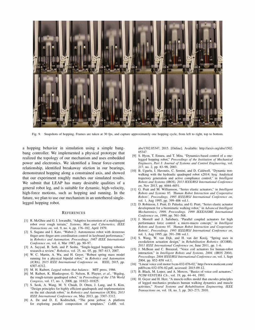
Fig. 9. Snapshots of hopping. Frames are taken at 30 fps, and capture approximately one hopping cycle, from left to right, top to bottom.
a hopping behavior in simulation using a simple bang-bang controller. We implemented a physical prototype thatrealized the topology of our mechanism and uses embeddedpower and electronics. We identified a linear force-currentrelationship, identified breakaway stiction in our bearings,demonstrated hopping along a constrained axis, and showedthat our experiment roughly matches our simulated results.We submit that LEAP has many desirable qualities of ageneral robot leg, and is suitable for dynamic, high-velocity,high-force motions, such as hopping and running. In thefuture, we plan to use our mechanism in an untethered single-legged hopping robot.
REFERENCES
[1] R. McGhee and G. I. Iswandhi, “Adaptive locomotion of a multileggedrobot over rough terrain,” Systems, Man and Cybernetics, IEEETransactions on, vol. 9, no. 4, pp. 176–182, April 1979.
[2] S. Sugano and I. Kato, “Wabot-2: Autonomous robot with dexterousfinger-arm–finger-arm coordination control in keyboard performance,”in Robotics and Automation. Proceedings. 1987 IEEE InternationalConference on, vol. 4, Mar 1987, pp. 90–97.
[3] A. Sayyad, B. Seth, and P. Seshu, “Single-legged hopping roboticsresearch-a review,” Robotica, vol. 25, no. 05, pp. 587–613, 2007.
[4] W. C. Martin, A. Wu, and H. Geyer, “Robust spring mass modelrunning for a physical bipedal robot,” in Robotics and Automation(ICRA), 2015 IEEE International Conference on. IEEE, 2015, pp.6307–6312.
[5] M. H. Raibert, Legged robots that balance. MIT press, 1986.[6] M. Raibert, K. Blankespoor, G. Nelson, R. Playter, et al., “Bigdog,
the rough-terrain quadruped robot,” in Proceedings of the 17th WorldCongress, vol. 17, no. 1, 2008, pp. 10 822–10 825.
[7] S. Seok, A. Wang, M. Y. Chuah, D. Otten, J. Lang, and S. Kim,“Design principles for highly efficient quadrupeds and implementationon the mit cheetah robot,” in Robotics and Automation (ICRA), 2013IEEE International Conference on, May 2013, pp. 3307–3312.
[8] A. De and D. E. Koditschek, “The penn jerboa: A platformfor exploring parallel composition of templates,” CoRR, vol.
abs/1502.05347, 2015. [Online]. Available: http://arxiv.org/abs/1502.05347
[9] S. Hyon, T. Emura, and T. Mita, “Dynamics-based control of a one-legged hopping robot,” Proceedings of the Institution of MechanicalEngineers, Part I: Journal of Systems and Control Engineering, vol.217, no. 2, pp. 83–98, 2003.
[10] B. Ugurlu, I. Havoutis, C. Semini, and D. Caldwell, “Dynamic trot-walking with the hydraulic quadruped robot x2014; hyq: Analyticaltrajectory generation and active compliance control,” in IntelligentRobots and Systems (IROS), 2013 IEEE/RSJ International Conferenceon, Nov 2013, pp. 6044–6051.
[11] G. Pratt and M. Williamson, “Series elastic actuators,” in IntelligentRobots and Systems 95. ’Human Robot Interaction and CooperativeRobots’, Proceedings. 1995 IEEE/RSJ International Conference on,vol. 1, Aug 1995, pp. 399–406 vol.1.
[12] D. Robinson, J. Pratt, D. Paluska, and G. Pratt, “Series elastic actuatordevelopment for a biomimetic walking robot,” in Advanced IntelligentMechatronics, 1999. Proceedings. 1999 IEEE/ASME InternationalConference on, 1999, pp. 561–568.
[13] J. Morrell and J. Salisbury, “Parallel coupled actuators for highperformance force control: a micro-macro concept,” in IntelligentRobots and Systems 95. ’Human Robot Interaction and CooperativeRobots’, Proceedings. 1995 IEEE/RSJ International Conference on,vol. 1, Aug 1995, pp. 391–398 vol.1.
[14] S. Wang, W. van Dijk, and H. van der Kooij, “Spring uses inexoskeleton actuation design,” in Rehabilitation Robotics (ICORR),2011 IEEE International Conference on, June 2011, pp. 1–6.
[15] J. McBean and C. Breazeal, “Voice coil actuators for human-robotinteraction,” in Intelligent Robots and Systems, 2004. (IROS 2004).Proceedings. 2004 IEEE/RSJ International Conference on, vol. 1, Sept2004, pp. 852–858 vol.1.
[16] “Linear voice coil motor lvcm-032-076-02,” http://www.moticont.com/pdf/lvcm-032-076-02.pdf, accessed: 2015-09-12.
[17] B. Black, M. Lopez, and A. Morcos, “Basics of voice coil actuators,”PCIM-VENTURA CA-, vol. 19, pp. 44–44, 1993.
[18] H. Geyer and H. Herr, “A muscle-reflex model that encodes principlesof legged mechanics produces human walking dynamics and muscleactivities,” Neural Systems and Rehabilitation Engineering, IEEETransactions on, vol. 18, no. 3, pp. 263–273, 2010.