
Design of a High-efficient Friction Clutch Apparatus...
22
Design of a High-efficient Friction Clutch Apparatus for Vehicle Applications Using Self-Energizing Mechanism Sooyoung Kim 1) Seibum B Choi* 1) Saebom Kim 2) 1) Department of Mechanical Engineering, KAIST, 291 Daehak-ro, Yuseong-gu, Daejeon 305-701, Korea 2) Clutch Core Development Team, Hanon Systems, 1689-1 Sinil-dong, Daedeok-gu, Daejeon, Korea [email protected], *[email protected], [email protected] Keywords Automotive clutch; Clutch actuator; Friction clutch design; Self-energizing effect; Torque amplification Abstract This study proposes a new design for a friction clutch actuator using the self- energizing principle for vehicle applications such that the power consumption for the clutch control is significantly reduced. The self-energizing effect can be created through simply adding wedge structures to a conventional clutch system, and it assists in significantly reducing the actuation energy of the clutch with little additional cost. In this paper, a mathematical model of the clutch actuation system is derived based on static force analyses with particular emphasis on the torque amplification factor due to the self-energizing effect. The slope angles of the wedges in the proposed clutch actuator are determined in order that the clutch system ensures appropriate torque amplification while considering various factors such as friction coefficient variations and return spring force. In addition, model-based analyses of the new clutch actuator system are conducted in order to predict the dynamic effects of the self-energizing mechanism on the system, particularly for the clutch engagement process. The feasibility of the proposed clutch design and its high energy efficiency are verified experimentally using three prototypes with different slope angles. Nomenclature leaf k : elastic modulus of leaf spring c C : clutch geometry constant 1 f F : friction force on disk 2 f F : friction force on wedge surface leaf F : leaf spring force M F : electromagnetic force N F : normal force on disk R F : reaction force on wedge surface tor F : torsion spring force da J : inertia of disk assembly p J : inertia of pulley
Transcript of Design of a High-efficient Friction Clutch Apparatus...

Design of a High-efficient Friction Clutch Apparatus for Vehicle Applications Using Self-Energizing Mechanism
Sooyoung Kim1) Seibum B Choi*1) Saebom Kim2) 1) Department of Mechanical Engineering, KAIST, 291 Daehak-ro, Yuseong-gu, Daejeon 305-701, Korea 2) Clutch Core Development Team, Hanon Systems, 1689-1 Sinil-dong, Daedeok-gu, Daejeon, Korea [email protected], *[email protected], [email protected]
Keywords Automotive clutch; Clutch actuator; Friction clutch design; Self-energizing effect; Torque amplification
Abstract This study proposes a new design for a friction clutch actuator using the self-energizing principle for vehicle applications such that the power consumption for the clutch control is significantly reduced. The self-energizing effect can be created through simply adding wedge structures to a conventional clutch system, and it assists in significantly reducing the actuation energy of the clutch with little additional cost. In this paper, a mathematical model of the clutch actuation system is derived based on static force analyses with particular emphasis on the torque amplification factor due to the self-energizing effect. The slope angles of the wedges in the proposed clutch actuator are determined in order that the clutch system ensures appropriate torque amplification while considering various factors such as friction coefficient variations and return spring force. In addition, model-based analyses of the new clutch actuator system are conducted in order to predict the dynamic effects of the self-energizing mechanism on the system, particularly for the clutch engagement process. The feasibility of the proposed clutch design and its high energy efficiency are verified experimentally using three prototypes with different slope angles.
Nomenclature leafk : elastic modulus of leaf spring
cC : clutch geometry constant
1fF : friction force on disk
2fF : friction force on wedge surface
leafF : leaf spring force
MF : electromagnetic force
NF : normal force on disk
RF : reaction force on wedge surface
torF : torsion spring force
daJ : inertia of disk assembly
pJ : inertia of pulley

dR : effective radius of friction lining on disk
torR : effective radius of torsion spring
wR : effective radius of wedge location
cT : clutch torque
LT : compressor load
pT : pulley torque a : slope angle of wedges
dd : displacement of disk
1m : dynamic friction coefficient of disk
1sm : static friction coefficient of disk
2m : dynamic friction coefficient of wedge surface
dw : angular velocity of disk
pw : angular velocity of pulley
d¡ : dynamic amplification factor of force
s¡ : static amplification factor of force
1. Introduction
Improving the energy efficiency of ground vehicles has been a key issue in global environmental
problems and the global energy crisis. For decades, there has been significant progress in increasing the
efficiency of individual automotive systems that include internal combustion engines, power
transmission systems, and other hydraulic and electrical components. Furthermore, the efficiency of
delivering the mechanical power produced by an engine is an important part of the energy efficiency
improvements. The engine power is predominantly transmitted to the wheels through the transmission
systems, but it is also used to mechanically drive various components such as turbochargers and air
conditioning (A/C) systems. In order to engage or disengage the power transmissions through these
subsystems, friction clutches (wet or dry) are commonly used. Because the automatic control of the
clutches performed by several types of actuators (e.g. hydraulics and motors) requires non-negligible
power consumption, it is desirable to reduce the energy consumed for the clutch actuation. Moreover,
improving the efficiency of the clutch actuators is increasingly important because the power transfer
and distribution controls, such as those in four-wheel drive and hybrid electric drive systems, are
becoming increasingly popular.1, 2
Previously, many studies have been conducted on new actuator designs that improve the
performance of the conventional systems in various fields, e.g. a rotary linear actuator using
piezoelectric translators,3 a serial dual actuator with planetary gear train,4 and an electromechanical
clutch actuator for automated manual transmissions.5 For electromagnetic actuators, researchers have

attempted to reduce the coil resistance and optimize the magnetic flux in order to reduce the power
consumption of the actuators.6, 7 In addition to the previous research, a more fundamental change is
needed as a solution to the problem while simultaneously considering the practical aspects. Hence, this
paper proposes a highly efficient clutch actuator design using the self-energizing principle for a vehicle
A/C system as an example of automotive friction clutches.
Using the self-energizing principle, the actuation energy can be significantly reduced in order to
create the same amount of clutch engagement force. The self-energizing mechanism recycles the
frictional energy, which is normally dissipated in the clutch during its engagement, to boost the
actuation force. This mechanism has already been used in several vehicle applications, including
conventional drum brakes, synchronizers, and electronic wedge brakes (EWBs).8, 9 Fujii et al.
developed a mathematical model of a wet band brake to describe its dynamics properties and self-
energizing mechanism.10 Park et al. and Jo et al. investigated the self-energizing effect of newly
designed EWBs and controlled them.11, 12 Efficient clutch actuators for automotive transmission
systems have also been developed based on the self-energizing principle.13, 14 In these studies, the
torque amplification of the actuators was achieved using non-circular gears or racks arranged in a
wedge shape. Yao et al. examined the control problems of a self-energizing clutch for automatic
transmissions considering its dynamic behavior.15
In this paper, a new electromagnetic clutch for a vehicle A/C system is implemented through adding
wedge blocks to the clutch disk of a conventional system. Considering mass production, this design
must be cost effective: through adding only small inexpensive components to the system, its power
consumption is significantly reduced in proportion to the amplification factor of the engagement force,
and the actuation coil size can also be reduced accordingly.
The remainder of this paper is organized as follows. In Section 2, the concept of the self-energizing
mechanism is introduced and the mathematical model for the proposed clutch actuator is derived. The
design considerations for the wedge clutch system and detailed discussions are presented in Section 3.
In Section 4, model-based analyses of the clutch system are conducted in order to predict the influences
of the self-energizing mechanism on the clutch engagement process. Finally, in Section 5, the validity
and effectiveness of the proposed clutch actuator are verified experimentally using three different
prototypes on an A/C test bench.
2. Mathematical Formulation of the Self-Energizing Mechanism
2.1 System overview
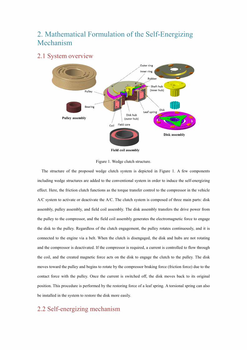
Figure 1. Wedge clutch structure.
The structure of the proposed wedge clutch system is depicted in Figure 1. A few components
including wedge structures are added to the conventional system in order to induce the self-energizing
effect. Here, the friction clutch functions as the torque transfer control to the compressor in the vehicle
A/C system to activate or deactivate the A/C. The clutch system is composed of three main parts: disk
assembly, pulley assembly, and field coil assembly. The disk assembly transfers the drive power from
the pulley to the compressor, and the field coil assembly generates the electromagnetic force to engage
the disk to the pulley. Regardless of the clutch engagement, the pulley rotates continuously, and it is
connected to the engine via a belt. When the clutch is disengaged, the disk and hubs are not rotating
and the compressor is deactivated. If the compressor is required, a current is controlled to flow through
the coil, and the created magnetic force acts on the disk to engage the clutch to the pulley. The disk
moves toward the pulley and begins to rotate by the compressor braking force (friction force) due to the
contact force with the pulley. Once the current is switched off, the disk moves back to its original
position. This procedure is performed by the restoring force of a leaf spring. A torsional spring can also
be installed in the system to restore the disk more easily.
2.2 Self-energizing mechanism

Figure 2. Clutch disk assembly.
The disk assembly of the wedge clutch system is presented in Figure 2. As the wedge and stopper
structures are installed in addition to the standard clutch, the self-energizing effect occurs such that the
engagement force is amplified. Both the stopper and the pulley are physically fixed in the vertical
direction. The magnetic force brings the wedges of the disk into contact with the wedges of the stopper
during engagement. The normal force acting on the surface of the disk wedges presses the disk against
the pulley, which forces it to engage deeper and also press against the surface of the wedges on the
stopper. This process occurs repeatedly and results in the vertical normal force on the disk becoming
significantly larger than the actual magnetic force, particularly with the increased friction coefficient
between the pulley and the disk.
2.3 Amplification factor of the clutch engagement force The self-energizing effect can be interpreted as the amplification factor of the clutch engagement
force. The amplification of the engagement force implies that a smaller amount of magnetic force and
current are required to actuate the clutch system compared with the conventional system. The
amplification factor can be derived based on the static force balance analysis through drawing a free
body diagram of the system.
Figure 3. Free body diagram of the wedge clutch system.
Figure 3 presents the free body diagram for the clutch disk assembly when it is engaged. Considering
the moment balance at the disk in rotating direction, equation (1) is derived as follows:
1 2sin cos ,d f w R w f tor tor d dR F R F R F R F Ja a w- - - = & (1)
where a , 1fF , RF , 2fF , and torF are the slope angle of the wedge blocks, the clutch friction force,
the normal force on the wedge surface, the friction force on the wedge surface, and the torsion spring
force, respectively. In equation (1), dR , wR , and torR are the effective radii of the friction lining on the
disk, the wedge locations, and the torsion spring.
In order to derive the static amplification factor for analyses of the proposed system, the operating
phase of the clutch is assumed as steady states where the clutch is fully engaged, i.e. 0dw =& and the
force amplification effect induced during the engagement still remains. Thus, equation (1) is reduced to
equation (2) as follows:
1 2sin cos 0.d f w R w f tor torR F R F R F R Fa a- - - = (2)
Considering the force balance in a vertical direction and assuming no displacement in that direction,
equation (3) is derived as follows:
2cos sin 0,N R M f leafF F F F Fa a- - + + = (3)
where MF , NF , and leafF are the magnetic force, the normal force from the pulley, and the leaf
spring force, respectively.
When the dynamic friction coefficient of the pulley surface is denoted as 1m , the compressor
braking force can be expressed as equation (4):
1 .B NF Fm= (4)
Likewise, the friction force acting on the surface of the wedges is described as follows:
2 ,f RF Fm= (5)
where 2m is the friction coefficient of the wedge surface.
Substituting equations (4) and (5) into equation (2), it can be arranged with respect to the normal force
on the wedge surface RF as follows:
( )1
2
.sin cos
d N tor torR
w
R F R FFRm
a m a-
=+
(6)
In the same manner, combining equation (3) with equation (5), the equation for the normal force on the
pulley surface NF can be obtained as described in equation (7).
2(cos sin ).N M leaf RF F F F a m a= - + - (7)
Then, the amplification factor s¡ of the engagement force by the self-energizing effect is expressed
as in equation (8) through combining equations (6) and (7).
( )
( )22
22 1 1 2
tan(1 tan )1 , where .tan tan tan
w
leafN tor tor Bs
w wM M w M
d d
RFF F R RG G R RF F R F
R R
a mm aa m a m m m m a
+æ ö-¡ = = - - =ç ÷ç ÷+è ø + - +
(8)
In equation (8), G is the original amplification factor determined using the characteristics of the
clutch system, and the terms in the parentheses represent the amount of factor reduction due to the
torsion spring and leaf spring.
2.4 Amplification factor of the clutch torque capacity The torque capacity, which is the maximum transmittable torque of the clutch and is one of the most
representative quantities that demonstrates the performance of the energy efficient clutch systems, can
be significantly increased using the self-energizing principle. If the static friction coefficient of the
clutch is not changed during its operation, the torque amplification factor might be equal to the force
amplification factor. In order to investigate the characteristics of the static friction, experiments with
the conventional clutch system were conducted. The measured static friction coefficient values
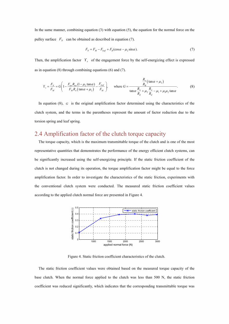
according to the applied clutch normal force are presented in Figure 4.
Figure 4. Static friction coefficient characteristics of the clutch.
The static friction coefficient values were obtained based on the measured torque capacity of the
base clutch. When the normal force applied to the clutch was less than 500 N, the static friction
coefficient was reduced significantly, which indicates that the corresponding transmittable torque was
1000 1500 2000 2500 30000
0.1
0.2
0.3
0.4
0.5
stat
ic fr
ictio
n co
effic
ient
(-)
applied normal force (N)
static friction coefficient
equally reduced. However, when the normal force was larger than approximately 1700 N, the friction
coefficient was almost constant, which implies that the normal force was proportional to the clutch
torque in that range. Based on these characteristics, it is inferred that the amplification factor of the
normal force differs from the corresponding torque factor because the static friction coefficient can be
changed when the normal force is amplified by the self-energizing mechanism. Considering this, the
amplification factor of the clutch torque capacity is described as follows:
,max_ 1 _
,max_ 1 _
,c w s ws
c o s o
TT
mm
= ¡ (9)
where ,max_c oT , ,max_c wT , 1 _s om , and 1 _s wm are the torque capacities and static friction coefficients of
the base and wedge clutches, respectively.
3. Design Considerations and Analyses
3.1 Amplification factor of the engagement force The amplification factor of the engagement force is the most important factor in the design of a
wedge clutch system. The wedge slope angle a should be appropriately designed in order that an
appropriate amplification factor is achieved by the wedge structure. Referring to equation (8), the
amplification factor is affected by five factors: a , 1m , 2m , leafF , and torF . Because there are too
many variables that increase the difficulty of the analysis, it is assumed that some variables have
nominal values that can be determined empirically. The torsion spring, which is an optional component,
was assumed to be not used in the system. For the clutch system without a torsion spring, equation (8)
can be simplified as follows:
1 .leafNs
M M
FF GF F
æ ö¡ = = -ç ÷
è ø (10)
It is assumed that 0.05w dR R m= = , 59leafF N= , 2200MF N= , and 1m have nominal values of
0.25–0.45 and 2m has a value of 0.1–0.4. When the friction coefficient 1m , which rarely changes once
the clutch system is being engaged, is fixed to 0.25, 0.3, 0.35, 0.4, and 0.45, the variations in the
amplification factor according to 2m and a can be determined as depicted in Figure 5.

(a)
(b)
(c)
(d)
0.1 0.15 0.2 0.25 0.3 0.35 0.4μ
2
1
1.5
2
2.5
3
forc
e am
plifi
catio
n fa
ctor
when μ1=0.3
α=21˚α=24˚α=27˚α=30˚α=33˚
0.1 0.15 0.2 0.25 0.3 0.35 0.4
μ2
1
2
3
4
5when μ
1=0.4
α=21˚α=24˚α=27˚α=30˚α=33˚
(e)
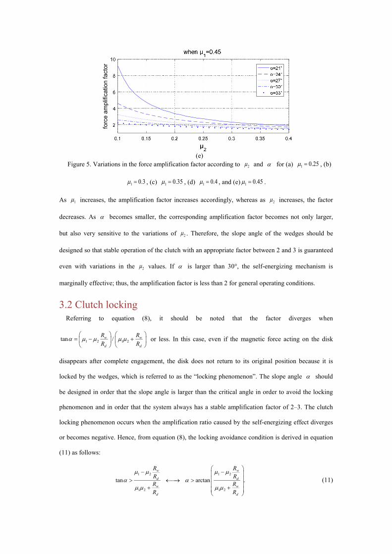
Figure 5. Variations in the force amplification factor according to 2m and a for (a) 1 0.25m = , (b)
1 0.3m = , (c) 1 0.35m = , (d) 1 0.4m = , and (e) 1 0.45m = .
As 1m increases, the amplification factor increases accordingly, whereas as 2m increases, the factor
decreases. As a becomes smaller, the corresponding amplification factor becomes not only larger,
but also very sensitive to the variations of 2m . Therefore, the slope angle of the wedges should be
designed so that stable operation of the clutch with an appropriate factor between 2 and 3 is guaranteed
even with variations in the 2m values. If a is larger than 30°, the self-energizing mechanism is
marginally effective; thus, the amplification factor is less than 2 for general operating conditions.
3.2 Clutch locking Referring to equation (8), it should be noted that the factor diverges when
1 2 1 2tan /w w
d d
R RR R
a m m m mæ ö æ ö
= - +ç ÷ ç ÷è ø è ø
or less. In this case, even if the magnetic force acting on the disk
disappears after complete engagement, the disk does not return to its original position because it is
locked by the wedges, which is referred to as the “locking phenomenon”. The slope angle a should
be designed in order that the slope angle is larger than the critical angle in order to avoid the locking
phenomenon and in order that the system always has a stable amplification factor of 2–3. The clutch
locking phenomenon occurs when the amplification ratio caused by the self-energizing effect diverges
or becomes negative. Hence, from equation (8), the locking avoidance condition is derived in equation
(11) as follows:
1 2 1 2
1 2 1 2
tan arctan .
w w
d d
w w
d d
R RR RR RR R
m m m ma a
m m m m
æ ö- -ç ÷ç ÷> ¬¾® >ç ÷+ +ç ÷è ø
(11)
forc
e am
plifi
catio
n fa
ctor
When the nominal values of 1m and 2m are known empirically, the corresponding a to avoid the
clutch locking can be calculated. Assuming that 1m is between 0.25 and 0.45, and 2m is 0.05–0.4, the
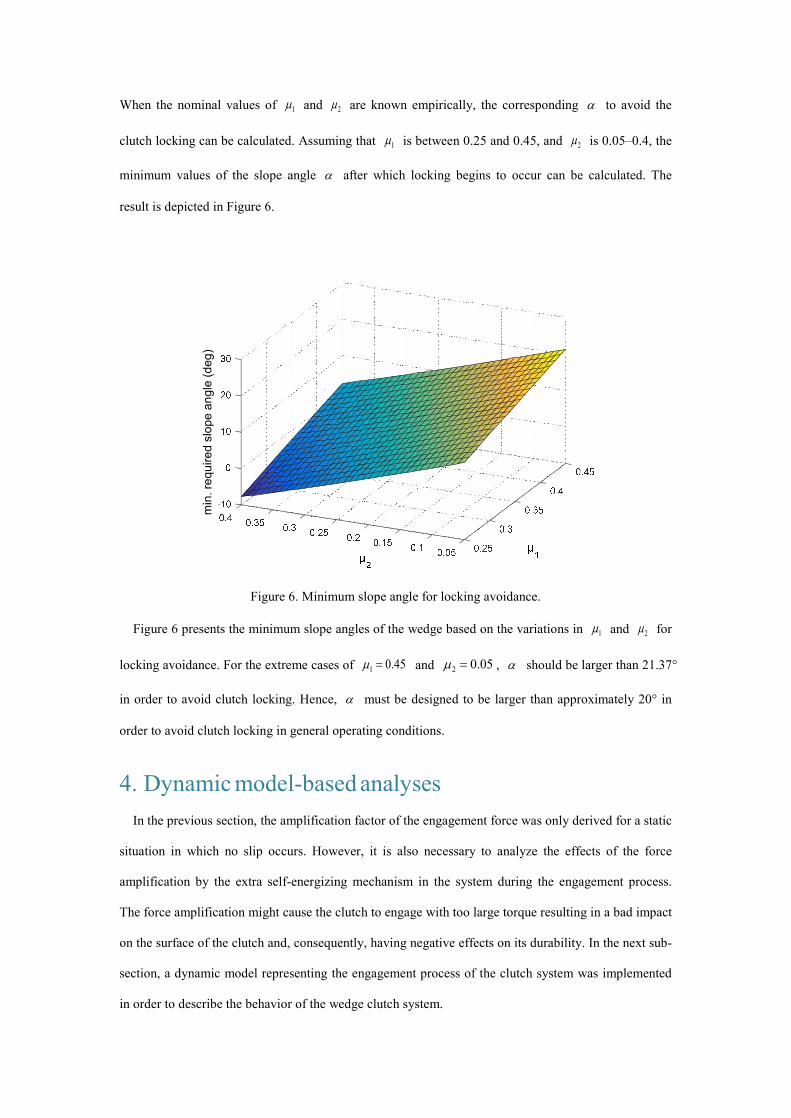
minimum values of the slope angle a after which locking begins to occur can be calculated. The
result is depicted in Figure 6.
Figure 6. Minimum slope angle for locking avoidance.
Figure 6 presents the minimum slope angles of the wedge based on the variations in 1m and 2m for
locking avoidance. For the extreme cases of 1 0.45m = and 2 0.05m = , a should be larger than 21.37°
in order to avoid clutch locking. Hence, a must be designed to be larger than approximately 20° in
order to avoid clutch locking in general operating conditions.
4. Dynamic model-based analyses
In the previous section, the amplification factor of the engagement force was only derived for a static
situation in which no slip occurs. However, it is also necessary to analyze the effects of the force
amplification by the extra self-energizing mechanism in the system during the engagement process.
The force amplification might cause the clutch to engage with too large torque resulting in a bad impact
on the surface of the clutch and, consequently, having negative effects on its durability. In the next sub-
section, a dynamic model representing the engagement process of the clutch system was implemented
in order to describe the behavior of the wedge clutch system.
min
. req
uire
d sl
ope
angl
e (d
eg)
4.1 Dynamic modeling Considering the torque balance relationships, the dynamics of the clutch system are described as
follows:
,p p p cJ T Tw = -& (12)
,da d c LJ T Tw = -& (13)
where pJ , daJ , pw , dw , pT , and cT are the inertia of the pulley, the inertia of the disk assembly, the
angular speeds of the pulley and disk, the pulley torque delivered from the engine, and the clutch
torque, respectively.
When the current is flowing through the coil, the electromagnetic force MF causes the disk move in
the direction of the force, and the displacement causes a restoring spring force leafF on the disk in the
opposite direction. Defining dd as the displacement of the disk and leafk as the elastic modulus of
the leaf spring, the leaf spring force is modelled as follows:
.leaf leaf dF k d= (14)
The net normal force acting on the disk is M leafF F- . In general, the torque transmitted through the
clutch is increased with the normal force during the engagement. These properties can be described as
follows:16, 17
1 1ˆ ( ) ,c N c M leaf cT F C F F Cm m= = - (15)
where cC is the effective area of the clutch related to its geometry. Here, it is assumed that the
dynamic friction coefficient of the clutch is slowly varying in order that it is constant during the gear
shift. For a more detailed discussion on the dynamic friction coefficient characteristics, refer to the
reference.16
The compressor load torque LT is known to utilize equations (12)–(15), but it cannot be measured
using sensors for production A/C systems. Furthermore, the compressor load varies according to many
different factors; thus, it is difficult to estimate the load values accurately in real time. The detailed
modeling process of the compressor torque is not in the scope of this study: refer to previous studies18-
20 for the modeling. When the actual value of the clutch torque is known, the compressor load can be
calculated simply using equation (16) during engagement:
L̂ c da dT T J w= - & . (16)
It may be argued that equation (16) is not practical because measuring the clutch torque in real time
is not possible. However, equation (16) can be utilized for offline calculation of the compressor load
when the clutch torque data are given from a test bench. This equation is useful for the offline analysis
of the clutch dynamic properties due to its simplicity.
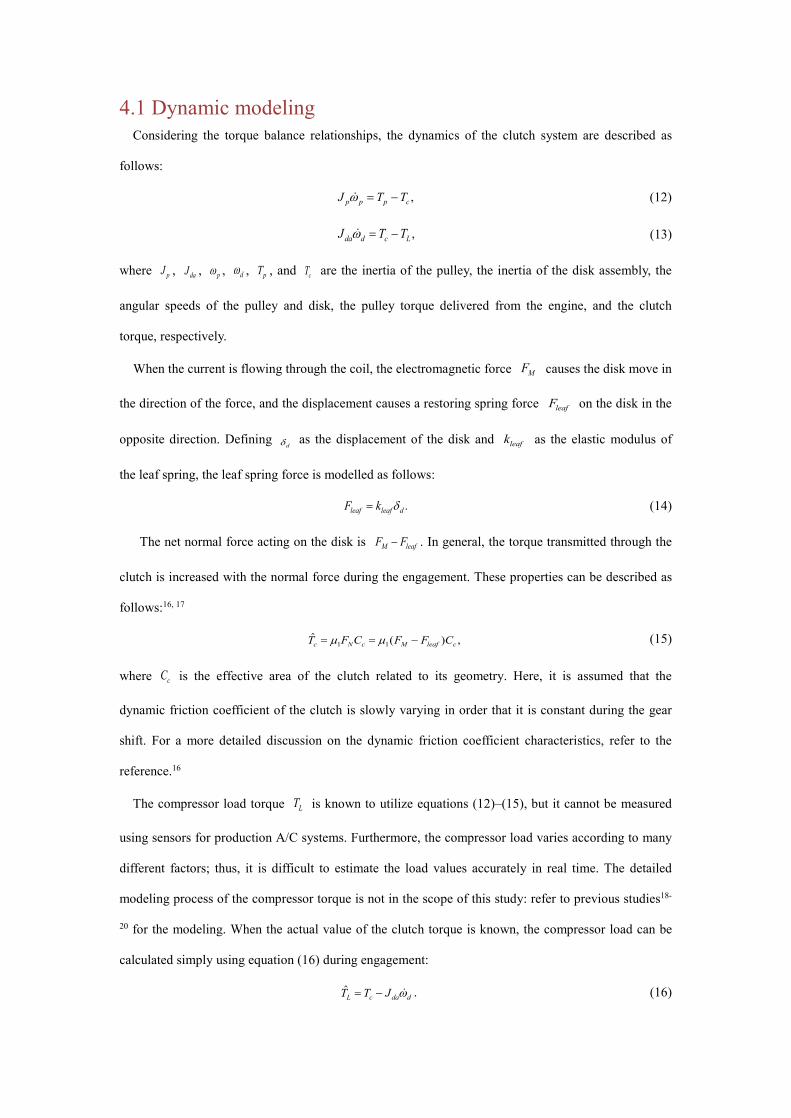
4.2 Model validation Through combining equations (13), (14), (15), and (16), the rotating speed of the disk can be
calculated. Comparison plots of the experiment results and simulation using the model are presented in
Figure 7. The parametric values used in the clutch model are as follows: 1 0.32m = , 98.1 /leafk N mm= ,
0.004485cC = , and 20.000421daJ kgm= . In estimating the rotating speed of the disk, the model is set to
maintain a constant speed once the disk is fully engaged, while the actual measured speed remains
oscillatory. The results verify that the model can precisely describe the characteristics of the clutch
torque and disk speed during the clutch engagement.
(a)
(b) Figure 7. Model validation: (a) clutch torque and (b) disk speed.
4.3 Model-based analyses of the wedge clutch system The basic operating principles of the wedge clutch apparatus are the same as those of a conventional
clutch. The only difference is that the wedges and some structural components such as stoppers are
0.02 0.03 0.04 0.05 0.06 0.07 0.08 0.090
5
10
15
time(s)
torq
ue (N
m)
simulationexperiment
0.02 0.03 0.04 0.05 0.06 0.07 0.08 0.090
100
200
300
400
500
600
time(s)
disk
spe
ed (r
ad/s
)
simulationexperiment
added to the wedge system; thus, the disk assembly inertia of the system differs slightly from that of a
conventional system. In addition, due to the self-energizing effect generated by the wedges, the clutch
normal force is amplified when the same amount of current input is applied.
Most parameters that affect the amplification factor, including the electromagnetic force and angular
speed of the disk, vary while the clutch is engaged. The original moment balance in equation (1) that
considers the inertia effect is used to derive the dynamic force amplification factor. Combining
equation (1) with equations (4) and (5), equation (17) is derived as follows:
( )1
2
.sin cos
d N tor tor d dR
w
R F R F JFR
m wa m a- -
=+
& (17)
It should be noted that the variations in the displacement of the disk in the axial direction do not need
to be considered because the displacement caused by the magnetic force is constant after the disk
makes contact with the pulley. Hence, substituting equation (17) into equation (7), the dynamic
amplification factor is derived as follows when 0torF = :
( )
2
2
(1 tan )1 , where .tan
leafN d dd
M M M w
FF JG I IF F F R
w m aa m
æ ö -¡ = = - - =ç ÷
+è ø
& (18)
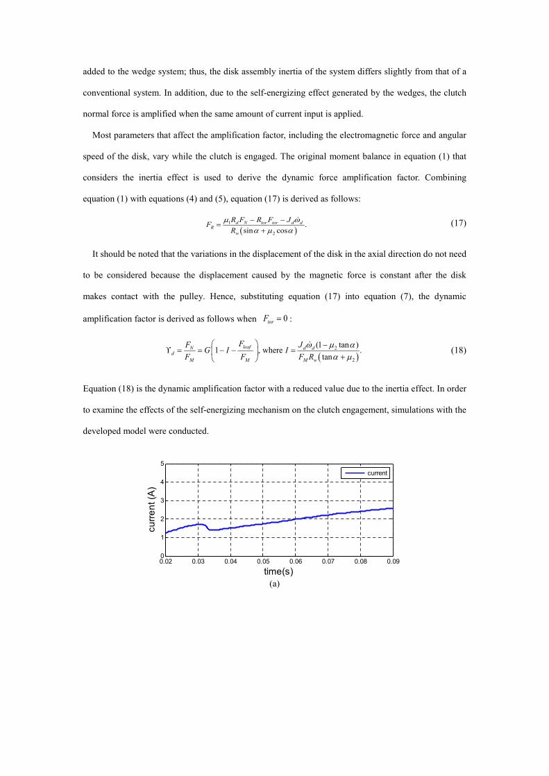
Equation (18) is the dynamic amplification factor with a reduced value due to the inertia effect. In order
to examine the effects of the self-energizing mechanism on the clutch engagement, simulations with the
developed model were conducted.
(a)
0.02 0.03 0.04 0.05 0.06 0.07 0.08 0.090
1
2
3
4
5
time(s)
curre
nt (A
)
current

(b)
(c)
(d)
Figure 8. Model responses during the engagement ( 2 10, 0.18, 0.32torF m m= = = ): (a) current, (b) disk
displacement, (c) dynamic force amplification factor, and (d) disk speed.
Figure 8 presents the model responses of the three wedge clutch actuators with different angles when
the current input in Figure 8(a) is applied to each system under the assumption that 1m and 2m are
constant during the engagement. The measured speed data of the disk used to calculate the compressor
load was processed with a low pass filter in order to remove the noise. With the self-energizing
mechanism, the torque was amplified, which resulted in faster engagement of the clutch compared with
the conventional clutch (Figures 8(c) and 8(d)). Thus, the time for the complete engagement (lock-up
time) shortened along with the increased amplification factor. In order to investigate the effect of the
torque amplification on the clutch durability, consider the frictional energy dE dissipated in the clutch
0.02 0.03 0.04 0.05 0.06 0.07 0.08 0.090
0.2
0.4
0.6
0.8
1
time(s)
disp
lace
men
t (m
m)
disk displacement
0.03 0.04 0.05 0.06 0.07 0.08 0.090
1
2
3
4
time(s)
ampl
ifica
tion
gain
α=21˚α=24˚α=27˚
0.03 0.04 0.05 0.06 0.07 0.08 0.090
100
200
300
400
500
600
time(s)
disk
spe
ed(ra
d/s)
α=21˚α=24˚α=27˚base
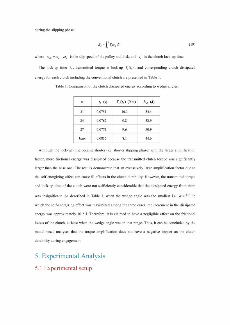
during the slipping phase:
0,
lt
d c dpE T dtw= ò (19)
where dp p dw w w= - is the slip speed of the pulley and disk, and lt is the clutch lock-up time.
The lock-up time lt , transmitted torque at lock-up ( )c lT t , and corresponding clutch dissipated
energy for each clutch including the conventional clutch are presented in Table 1.
Table 1. Comparison of the clutch dissipated energy according to wedge angles.
Although the lock-up time became shorter (i.e. shorter slipping phase) with the larger amplification
factor, more frictional energy was dissipated because the transmitted clutch torque was significantly
larger than the base one. The results demonstrate that an excessively large amplification factor due to
the self-energizing effect can cause ill effects in the clutch durability. However, the transmitted torque
and lock-up time of the clutch were not sufficiently considerable that the dissipated energy from them
was insignificant. As described in Table 1, when the wedge angle was the smallest i.e. 21a = o in
which the self-energizing effect was maximized among the three cases, the increment in the dissipated
energy was approximately 10.2 J. Therefore, it is claimed to have a negligible effect on the frictional
losses of the clutch, at least when the wedge angle was in that range. Thus, it can be concluded by the
model-based analyses that the torque amplification does not have a negative impact on the clutch
durability during engagement.
5. Experimental Analysis
5.1 Experimental setup
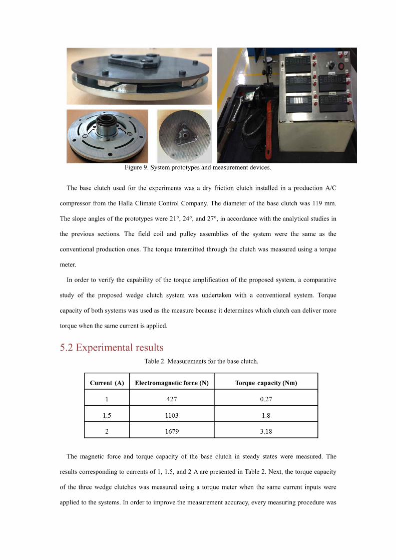
Figure 9. System prototypes and measurement devices.
The base clutch used for the experiments was a dry friction clutch installed in a production A/C
compressor from the Halla Climate Control Company. The diameter of the base clutch was 119 mm.
The slope angles of the prototypes were 21°, 24°, and 27°, in accordance with the analytical studies in
the previous sections. The field coil and pulley assemblies of the system were the same as the
conventional production ones. The torque transmitted through the clutch was measured using a torque
meter.
In order to verify the capability of the torque amplification of the proposed system, a comparative
study of the proposed wedge clutch system was undertaken with a conventional system. Torque
capacity of both systems was used as the measure because it determines which clutch can deliver more
torque when the same current is applied.
5.2 Experimental results Table 2. Measurements for the base clutch.
The magnetic force and torque capacity of the base clutch in steady states were measured. The
results corresponding to currents of 1, 1.5, and 2 A are presented in Table 2. Next, the torque capacity
of the three wedge clutches was measured using a torque meter when the same current inputs were
applied to the systems. In order to improve the measurement accuracy, every measuring procedure was
repeated five times, and the final measured value was the average of the five values for each clutch.
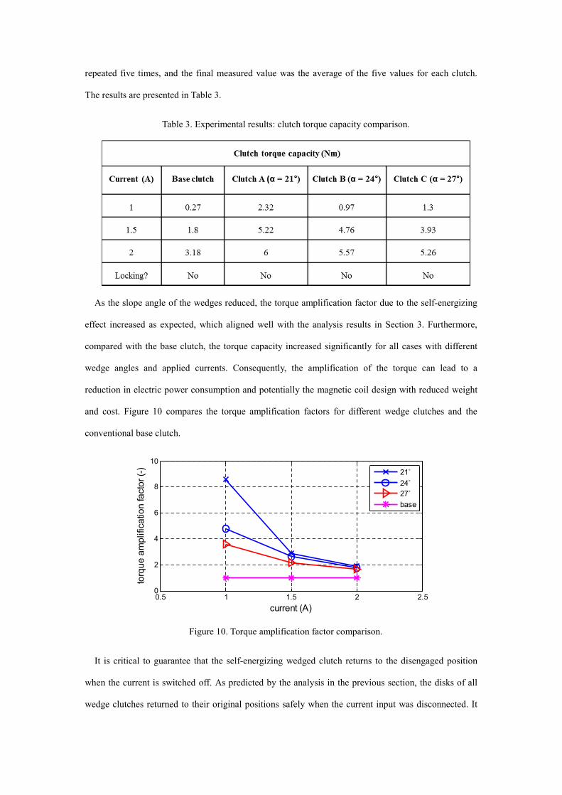
The results are presented in Table 3.
Table 3. Experimental results: clutch torque capacity comparison.
As the slope angle of the wedges reduced, the torque amplification factor due to the self-energizing
effect increased as expected, which aligned well with the analysis results in Section 3. Furthermore,
compared with the base clutch, the torque capacity increased significantly for all cases with different
wedge angles and applied currents. Consequently, the amplification of the torque can lead to a
reduction in electric power consumption and potentially the magnetic coil design with reduced weight
and cost. Figure 10 compares the torque amplification factors for different wedge clutches and the
conventional base clutch.
Figure 10. Torque amplification factor comparison.
It is critical to guarantee that the self-energizing wedged clutch returns to the disengaged position
when the current is switched off. As predicted by the analysis in the previous section, the disks of all
wedge clutches returned to their original positions safely when the current input was disconnected. It
0.5 1 1.5 2 2.50
2
4
6
8
10
torq
ue a
mpl
ifica
tion
fact
or (-
)
current (A)
21˚24˚27˚base

should be noted that the torque amplification factor increased as the applied current decreased because
when the current is sufficiently small, 1 _s om in equation (9) is sufficiently small that the torque factor
becomes significantly larger than the corresponding force factor. Moreover, a large variation of the
torque amplification factor during the operation of the clutch system adversely affects it and can cause
unstable operation. According to Figure 10, the torque amplification factor is highly sensitive to the
operating conditions for 21a = o and 24a = o . In contrast, the wedge clutch of 27a = o exhibited the
performance of torque amplification with an appropriate factor of 2–3 for all cases. Hence, it is
concluded that a slope angle of near 27° is appropriate for the wedge design of the target A/C friction
clutch. The experimental analysis also validated the effectiveness and feasibility of the proposed clutch
system to control the clutch engagement in an energy efficient way.
5.3 Validation of amplification factor model Because equation (9) was used to analyze the system design in the previous section, its accuracy of
modeling the torque amplification factor of a wedge clutch must be validated. In order to use equation
(9), all friction coefficient values including 1 _s om , 1 _s wm , and 2m should be known. However, the
static friction coefficient of the pulley surface in a wedge clutch 1 _s wm cannot be directly measured
because the corresponding amplified normal force is unknown. However, it can be estimated based on
the static friction characteristic curve described in Figure 4. For example, when the current applied to a
wedge clutch is larger than 1.5 A, the corresponding value of 1 _s wm is assumed to be 0.39 because the
amplified normal force is larger than 1700 N. Assuming that the nominal value of 2m is 0.18 and that
it does not change during the experiments, the estimated values of 1 _s wm are presented in Table 4. The
friction coefficients are assumed to be 0.39, except for two extreme cases when the current is 1 A.
Using the known 2m and the analysis results of Section 3, 1 _s wm is determined to be 0.29 for
27a = o and 0.31 for 24a = o . Using the parametric values in Table 4, the corresponding static
torque factor can be calculated using equation (9) as depicted in Figure 11.
Table 4. Estimated values of 1 _s wm .

Figure 11. Torque amplification factor model validation.
Figure 11 compares the calculated torque factors with the experimentally measured ones, which
validate that the torque factor modelled in equation (9) is accurate. Even though the estimated values of
1 _s wm were used in the model, equation (9) predicted the torque amplification factors well for all cases.
The friction coefficient of wedges 2m can be varied in each experiment; thus, assuming 2m as a
constant might be a primary cause of model errors, particularly when the current is 2 A. However, the
results prove that the self-energizing effect of the proposed system is well described by equations (8)
and (9), and the equations can be used for further analysis and design of such systems.
6. Conclusion
This paper proposed a new clutch actuator design using the self-energizing effect to reduce the
power consumption of the actuation. The proposed clutch actuator is based on a dry clutch for vehicle
A/C systems; however, the design methodology can be easily applied to other friction clutches for
vehicle applications. The influences of the pulley surface friction coefficient, the wedge surface friction
coefficient, and the leaf spring force on the amplification factor of the engagement force were analyzed
in order to determine the appropriate slope angle of the wedges. From the model analysis and
0.5 1 1.5 2 2.50
2
4
6
8
10
torq
ue a
mpl
ifica
tion
fact
or (-
)
current (A)
21˚ exp24˚ exp27˚ exp21˚ sim24˚ sim27˚ sim

experimental results, it was proposed that the slope angle of the wedges for the target clutch should be
near 27° in order to obtain the appropriate amplification factor while avoiding self-locking. Dynamic
modeling and analyses based on the developed model were also performed in order to investigate the
transient characteristics of the modified structure. The experimental results on a test bench with three
different prototypes indicated that the wedge clutch actuator system was significantly more efficient
than the conventional one because it can significantly amplify the engagement force, thus reducing the
actuation energy and potentially lowering the weight and cost of the actuation system.
Acknowledgment
This work was supported in part by the MSIP Ministry of Science, ICT and Future Planning, Korea,
under the ITRC Information Technology Research Center support program Grant IITP-2016-H8601-
16-1005 supervised by the IITP Institute for Information & communications Technology Promotion,
the BK21 plus program, and the National Research Foundation of Korea (NRF) grant funded by the
Korea government (MSIP) Grant 2010-0028680.
References
1. Kim H, Lee S and Hedrick J. Active yaw control for handling performance improvement by using traction force. International Journal of Automotive Technology. 2015; 16: 457-64. 2. Salmasi FR. Control strategies for hybrid electric vehicles: Evolution, classification, comparison, and future trends. IEEE Transactions on vehicular technology. 2007; 56: 2393-404. 3. Zhang Y, Liu G and Hesselbach J. On Development of a Rotary to Linear Actuator Using Piezoelectric Translators. Mechatronics, IEEE/ASME Transactions on. 2006; 11: 647-50. 4. Kim B-S, Song J-B and Park J-J. A serial-type dual actuator unit with planetary gear train: Basic design and applications. Mechatronics, IEEE/ASME Transactions on. 2010; 15: 108-16. 5. Moon S, Kim H and Hwang S. Development of automatic clutch actuator for automated manual transmissions. International Journal of Automotive Technology. 2005; 6: 461-6. 6. Karakoc K, Park EJ and Suleman A. Design considerations for an automotive magnetorheological brake. Mechatronics. 2008; 18: 434-47. 7. Pauvert V, Bernard N, Zaim M and Bonnefous J. Modelisation and optimization of clutch magnet actuator topologies. Industry Applications Conference, 2007 42nd IAS Annual Meeting Conference Record of the 2007 IEEE. IEEE, 2007, p. 853-60. 8. Glišović J, Radonjić R and Miloradović D. Experimental method for analyzing friction phenomenon related to drum brake squeal. Tribology in Industry. 2010; 32. 9. Luo F, Li J, Feng X and Zhang Y. Simulation and Analysis on a Self-Energizing Synchronizer of Transmission. SAE Technical Paper, 2015.
10. Fujii Y, Tobler W and Snyder T. Prediction of wet band brake dynamic engagement behaviour Part 1: Mathematical model development. Proceedings of the Institution of Mechanical Engineers, Part D: Journal of Automobile Engineering. 2001; 215: 479-92. 11. Jo C, Lee S, Song H, et al. Design and control of an upper-wedge-type electronic brake. Proceedings of the Institution of Mechanical Engineers, Part D: Journal of Automobile Engineering. 2010; 224: 1393-405. 12. Park H and Choi BS. Development of a Sensorless Control Method for a Self-Energizing Brake System Using Noncircular Gears. Control Systems Technology, IEEE Transactions on. 2013; 21: 1328-39. 13. Oh J, Kim J and Choi S. Design of Self-energizing Clutch Actuator for Dual Clutch Transmission. Mechatronics, IEEE/ASME Transactions on. 2015; PP. 14. Kim J and Choi SB. Design and modeling of a clutch actuator system with self-energizing mechanism. Mechatronics, IEEE/ASME Transactions on. 2011; 16: 953-66. 15. Yao J, Chen L, Liu F and Yin C. Experimental study on improvement in the shift quality for an automatic transmission using a motor-driven wedge clutch. Proceedings of the Institution of Mechanical Engineers, Part D: Journal of Automobile Engineering. 2014; 228: 663-73. 16. Vasca F, Iannelli L, Senatore A and Reale G. Torque transmissibility assessment for automotive dry-clutch engagement. Mechatronics, IEEE/ASME Transactions on. 2011; 16: 564-73. 17. Oh JJ, Choi SB and Kim J. Driveline modeling and estimation of individual clutch torque during gear shifts for dual clutch transmission. Mechatronics. 2014; 24: 449-63. 18. Gravdahl JT and Egeland O. Centrifugal compressor surge and speed control. Control Systems Technology, IEEE Transactions on. 1999; 7: 567-79. 19. Gravdahl JT, Egeland O and Vatland SO. Drive torque actuation in active surge control of centrifugal compressors. Automatica. 2002; 38: 1881-93. 20. Fink D, Cumpsty N and Greitzer E. Surge dynamics in a free-spool centrifugal compressor system. Journal of Turbomachinery. 1992; 114: 321-32.


![Friction Technology Ltd - Industrial Clutch · 2020. 9. 16. · Semi Semi 080623-03 Temperature ['CJ spac pressure [bar] friction TEST PROTOCOL FRICTION TEST BRAKE SYSTEM DATA PROCESSED](https://static.fdocuments.us/doc/165x107/613531a7dfd10f4dd73c3779/friction-technology-ltd-industrial-clutch-2020-9-16-semi-semi-080623-03-temperature.jpg)

