Design Methodology - Kinetic Architecture-libre
182
Design Methodology: Kinetic Architecture A THESIS Presented to the Graduate School Faculty of Engineering, Alexandria University In Partial Fulfillment of the Requirements for the Degree Of Master of Science In Architectural Engineering By Architect Soha Mohamed Abd El-Hady Fouad B.Sc. of Architecture Alexandria University July 2012
-
Upload
minecan-ioan-alexandru -
Category
Documents
-
view
121 -
download
9
description
arhitectura si design
Transcript of Design Methodology - Kinetic Architecture-libre

Design Methodology:
Kinetic Architecture
A THESIS
Presented to the Graduate School Faculty of Engineering, Alexandria University
In Partial Fulfillment of the Requirements for the Degree
Of Master of Science
In
Architectural Engineering
By
Architect
Soha Mohamed Abd El-Hady Fouad B.Sc. of Architecture Alexandria University
July 2012


VII
ABSTRACT Although immense changes occurred in the Egyptian built environment,
given products didn't consider occupants' changing needs and activities as well as changing environmental conditions. The research aimed to present non-traditional solutions in order to create environments able to respond, adapt and interact in motional behaviors.
Upon the belief that the fundamental knowledge of Kinetic Architecture can better assist architects to acquaint the need to enroll motion in the built environment; the thesis first presents different definitions for the term Kinetic Architecture. Next, it historically reviews the use of kineticism in the architectural field since the old ages until present. Also, it describes different trends to apply kineticism in the architectural environment accompanied with explanatory examples.
The technological achievement in different divisions of engineering such as structural, mechanical and materials engineering as well as information and communication technologies has an enormous effect on kinetic design. As a result, the second part of the thesis is dedicated to kinetic design process defining its main elements from structural innovation and materials advancement to embedded computation and at last adaptive architecture.
The research carries on an analytical study by highlighting fifteen architectural project adapting kineticism. The study is based on the different elements affecting the kinetic design process. The evaluating criteria include the way and reason for involving kineticism as well as the effect it has upon the indoor environment and the visual quality.
Finally, the thesis ends with concluding the effect of using kineticism in the architectural field. And, it suggests some systems to be applied to the Egyptian environment. Recommendations for further studies are represented to enrich applying the theory. Key Words: Kinetic, Kineticism, Motion, Adaptive, Responsive, Interactive.


IX
ACKNOWLEDGMENTS I would like to express my deep recognition and sincere appreciation to
Prof. Dr. Hany M. Abd El Gawad Ayad for his generous patience, valuable guidance, advice and precious time and effort throughout all stages of conducting this thesis. Also, I would like to express my truthful gratitude and sincere appreciation to Dr. Dina Sameh Taha for her endless patience, precious help, comments and continues encouragement and support to accomplish this work.
I am very grateful to all my friends and colleagues for their support and
help. I am thankful to Federica Sabbadini for her help providing me with research materials.
Finally, I would like to express my deep love and appreciation to my family
for all their love, care, support and assistance and for always being there for me.


Table of Contents
XI
TABLE OF CONTENTS
ABSTRACT .................................................................................................................................... VII ACKNOWLEDGMENTS ............................................................................................................... IX TABLE OF CONTENTS ................................................................................................................. XI LIST OF FIGURES ....................................................................................................................... XIII LIST OF TABLES .......................................................................................................................... XX INTRODUCTION ........................................................................................................................ XXI
A. BACKGROUND ....................................................................................................... 1
B. RESEARCH AIMS AND OBJECTIVES ................................................................. 3 C. MOTIVATION AND RESEARCH IMPORTANCE ............................................... 3 D. RESEARCH METHODOLOGY ............................................................................... 4 E. RESEARCH STRUCTURE ...................................................................................... 4
CHAPTER ONE: WHAT IS KINETIC ARCHITECTURE? ............................................................ 7 1. What is Kinetic Architecture? .................................................................................... 9 1.1. Kinetic Architecture Definition ................................................................................. 9 1.2. Historical Review ..................................................................................................... 11 1.3. Kinetic Trends in Architectural Environments ........................................................ 22
1.4. Summary .................................................................................................................. 28 CHAPTER TWO: KINETIC DESIGN KEY ELEMENTS ............................................................. 29
2. KINETIC DESIGN .................................................................................................. 31 2.1. Kinetic Design Key Elements .................................................................................. 31
2.1.2.1. Trends in Embedded Computation ..................................................... 35 2.1.2.2. Level of Control Mechanisms ............................................................ 38 2.1.2.3. Ways and Means of Embedded Computation .................................... 39 2.1.2.4. Typologies of Controlling Change ..................................................... 40
2.1.3.1. Living Environments .......................................................................... 42 2.1.3.2. Working Environments ...................................................................... 42 2.1.3.3. Entertainment Environments .............................................................. 42 2.1.3.4. Public Environments .......................................................................... 43
A.1. Research Problem: ..................................................................................... 2A.2. Research Hypothesis: ................................................................................ 3
1.3.1. Spatial Optimization Systems.................................................................. 221.3.2. Multi-Function Design ............................................................................ 231.3.3. Contextual Adaptability........................................................................... 251.3.4. Mobility ................................................................................................... 27
2.1.1. Structural Innovation and Materials Advancement ................................. 312.1.2. Embedded Computation .......................................................................... 34
2.1.3. Adaptable Architecture ............................................................................ 41

Table of Contents
XII
2.2. Summary .................................................................................................................. 44 CHAPTER THREE: KINETIC BUILDINGS' ANALYSIS ............................................................ 45
3. KINETIC BUILDINGS' ANALYSIS ...................................................................... 47 3.1. Architectural Projects: .............................................................................................. 47
3.2. Analysis: ................................................................................................................. 112
3.3. Summary: ............................................................................................................... 119 CONCLUSIONS AND RECOMMENDATIONS ......................................................................... 121 Conclusions .................................................................................................................................... 123 Recommendations: ......................................................................................................................... 128 REFERENCES .................................................................................................................................... i
3.1.1. Institut du Monde Arabe: ......................................................................... 483.1.2. GucklHupf ............................................................................................... 533.1.3. Floirac House "Maison à Bordeaux" ....................................................... 573.1.4. The Naked House .................................................................................... 613.1.5. Milwaukee Art Museum "Quadracci Pavilion" ....................................... 653.1.6. Gemini Haus ............................................................................................ 693.1.7. Dragspelhuset: ......................................................................................... 733.1.8. The Leaf Chapel: ..................................................................................... 773.1.9. QiZhong Forest Sports City Tennis Centre "Magnolia Stadium" ........... 813.1.10. Kiefer Technic Showroom ....................................................................... 853.1.11. Sliding House .......................................................................................... 893.1.12. The Olympic Tennis Center "Magic Box" .............................................. 933.1.13. Cherokee Studios Lofts ........................................................................... 973.1.14. The World Trade Center Transportation Hub ....................................... 1013.1.15. Dynamic Tower ..................................................................................... 105
3.2.1. Location: ................................................................................................ 1123.2.2. Structural Systems and Used Materials: ................................................ 1123.2.3. Indoor Environment Types: ................................................................... 1133.2.4. Kinetic Elements and Reasons for Motion: ........................................... 1143.2.5. Relation between Structural System and Used Materials: ..................... 1163.2.6. Relation between Structural System and Used Kinetic Elements: ........ 1163.2.7. Relation between Building Environments and Used Kinetic Elements:1173.2.8. Relation between Building Environments and Reasons for Motion: .... 1173.2.9. Ways of Controlling Kineticism and the Relation with Building Environments: ........................................................................................................... 1183.2.10. Kinetic Systems Effect on Buildings' Visual Quality: ........................... 119

List of Figures
XIII
LIST OF FIGURES
- Figure 1: Thesis Structure. .......................................................................................... 5
- Figure 2: (a) The Colosseum represented the first kinetic retractable roof covering the seating area around the arena (Pepe, 2001). (b) An intriguingly simple device invented by Thomas Jefferson for his home to allow both doors to open simultaneously whenever any is opened. As the device was concealed beneath the floor, its principle was not known until it was uncovered in 1953 (Zuk, 1970, P. 29). ................................................................................................................................... 11
- Figure 3: (a) A sketch showing how a drawbridge at medieval castle worked, typical of such structures that were precursors of modern bascule bridges (Koglin, 2003, P. 4). (b) A view of the entrance door and the drawbridge to Rocca Gradara – one of the best preserved medieval structures in Italy – which was built in 12th to the 15th centuries (GeoSearch.Italia, N/D). ............................................................................ 12
- Figure 4: (a) A scketch shows how a typical drawbridge works (Hall, N/D). (b) A scketch shows how a typical trunnion bascule bridge works (Ryall, 2000, P. 669). 13
- Figure 5: (a) A schematic of vertical lift bridge (S. Glover, 2007). (b) A rolling bascule bridge while closed (Chase Hill, 1927, P. 467). ........................................... 13
- Figure 6: (a) The construction of the Santa Barbara County bowl revolving stage in 1936 which was destroyed by El-Nino floods during 1939 in the United States of America (SantaBarbaraBowlFoundation, N/D). (b) Architect M. Engere Pettit and physician Lucien Pellegrine "heliotropic house" 1903 (Randl, 2008, P. 57). ........... 14
- Figure 7: A view for Saidman's revolving solarium, Aix Les-Bains, France (Petit, N/D). .......................................................................................................................... 15
- Figure 8: Max Taut's Rotating House, Frublicht (Dawn), 1920 (Randl, 2008, P. 67). ................................................................................................................................... 16
- Figure 9: Tatlin's Monument to the Third International, designed in 1919 (Randl, 2008, P. 68). .............................................................................................................. 17
- Figure 10: Villa Girasole from the air, with the courtyard of the rotating section facing uphill,1935 (Randl, 2008, P. 77). ................................................................... 18
- Figure 11: Villa Girasole: (a) lower floor plan where the villa can rotate 360 degrees over rail tracks (Davies, 2006, P. 87). (b) structural frame showing the spiral staircase as well as the tracks (Randl, 2008, P. 78). .................................................. 18
- Figure 12: The 1,400 square-foot revolving house built by Francois Massau in 1958 still turns, making a complete circle in 90 minutes, admitting more sunlight into its rooms as needed (Tagliabue, 2008). ......................................................................... 19
- Figure 13: (a) The Stuttgart Tower in Stuttgart, Germany (Smart-Travel-Germany.com, N/D). (b) The Dortmund's Florianturm in Dortmund, Germany (Janberg, N/D-a). (c) The concrete Henninger Turm in Frankfurt, Germany (Janberg, N/D-b). (d) The Cairo Tower in Cairo, Egypt (Wikipedia, 2004). ........... 20
List of Figures
XIV
- Figure 14: The Solaleya Dome House, a house for a clean and sustainable future (Solaleya, N/D). ......................................................................................................... 21
- Figure 15: (a) The Suite Vollard, the first fully revolving high-rise apartment building (Zeiler, 2011, P. 362). (b) A plan for the Suite Vollard showing the fixed core and the rotating part (van Poucke, 2008c). ........................................................ 21
- Figure 16: (a) Interlocking Transformation, an interior diagram (Fox, 2009, P. 32). (b) Interlocking Transformation, reconfigurable elements dividing sectors (Fox, 2009, P. 32). .............................................................................................................. 23
- Figure 17: The Bloomframe (HurksGeveltechniek, N/D). (a) In window state. (b) In balcony state. ............................................................................................................. 24
- Figure 18: (a) A diagram shows different ring units connected to each other while in use (Kapfinger, N/D). (b) A ring unit (Serrats, 2005, P. 380). .................................. 24
- Figure 19: (a) An exterior view for the Wind Veil (Kahn, 2000). (b) A close view for the aluminum panels of the Wind Veil (Kahn, 2000) .......................................... 25
- Figure 20: Convertible umbrellas for the courts of the Prophet's Holy Mosque in an opened and closed state (SL-RASCH-GMPH, N/D). ............................................. 26
- Figure 21: The Bengt Sjostrom/Starlight Theater. Study model shows the building's roof (mnartists.org, N/D) while: (a) opened and (b) closed. (d) An inner view for the kinetic roof while opened (Galindo, 2005, P. 78). .................................................... 26
- Figure 22: Mobile Dwelling Unit, the container plan while sub-volumes pushed out (fabprefab, N/D). ....................................................................................................... 27
- Figure 23: Mobile Dwelling Unit. (a) An exterior view while MDU in an opened state (Gardiner, 2003, P. 132). (b) An exterior view while the MDU in a closed state (Block, 2011). ............................................................................................................ 28
- Figure 24: Diagram shows kinetic structures typologies (Fox, N/D). ...................... 31
- Figure 25: (a) The Muscles Tower while activated (Detwiler, 2006). (b)The Carlos Moseley Music Pavilion while being transported to its location and being assembled (Mota, 2007). ............................................................................................................. 32
- Figure 26: (a) Two of the modular units of the Flare-façade system and their control mechanism (WHITEvoid, N/D). (b) A paper model for the Flare-façade system (WHITEvoid, N/D). .................................................................................................. 34
- Figure 27: The Kuwait Pavilion for Expo 92 while changing from closed state to opened one (Hawarny, 2008, P. 30). ......................................................................... 34
- Figure 28: (a) An interior view for Taipei 101 tuned mass damper (TMD) (Wikipedia, N/D). (b) A diagrame shows where the Tuned Mass Damper is located in Taipei 101 Building (Wikipedia, N/D). ................................................................ 35
- Figure 29: The Implant Matrix (InteractiveArchitecture.org, 2006). ........................ 36
- Figure 30: The AMX Whole Home Automation touch panel (AMX, N/D). ............ 37
- Figure 31: The Stereoscope Project while playing an animation on Toronto City Hall façade (AlternativeBerlin, 2010). .............................................................................. 38
- Figure 32: The Interactive Restaurant (RobotectureInteractiveArchitecture, N/D) .. 43

List of Figures
XV
- Figure 33: An external view for Institut du Monde Arabe (WikiArquitectura, 2010). ................................................................................................................................... 48
- Figure 34: (a) The Mashrabiya diaphragm used at Institut du Monde Arabe (Osmers, 2007). (b) Mashrabiya unit sketch (Prisse d’Avennes, 2007, P. 137). (c) Mashrabiya used in a Ottoman residential building near Khan El-Khalili, Cairo, Egypt (a.allegretti, 2012). .......................................................................................... 49
- Figure 35: An external view for the flat southern façade of Institut du Monde Arabe shows the "Mashrabiya Diaphragms" that were used (IMA, 2001). ......................... 49
- Figure 36: (a) A view for a group of the mashrabiya diaphragms while functioning (eliinbar, 2011). (b) A detail of the medium sized diaphragm (moreAEdesign, 2010). (c) A detail of small diaphragms (moreAEdesign, 2010). ....................................... 50
- Figure 37: A diagram showing reason for installing mashrabiya diaphragms on the southern façade (Yucel, 1989, P. 92). ....................................................................... 51
- Figure 38: An external view for GucklHupf while being opened (de la Torre, N/D). ................................................................................................................................... 53
- Figure 39: The GucklHupf plans where the red colored rectangular is the main area while the other parts are those being opened, slided or folded (de la Torre, N/D). .. 54
- Figure 40: The GucklHupf section where the red color indicates the accurate area when the structure is closed. Also this section shows the four different levels inside the structure (Ballard Bell, 2006, P. 125). ................................................................. 54
- Figure 41: Transformation in GucklHupf starting from the closed state (Olson, 2009). ........................................................................................................................ 55
- Figure 42: An exterior view for the Floirac House (OrgoneDesign, N/D). .............. 57
- Figure 43: Plans for the Floirac House showing different ways to access levels (Beck, N/D). The Blue color indicates the elevator platform, the red color indicates the main staircase, the green color indicates the service staircase and the yellow color indicates a staircase connecting two levels. ..................................................... 58
- Figure 44: Long section though the Floirac House, where the blue color indicates the elevator platform (Beck, N/D). (a) The elevator platform reaches the second floor. (b) The elevator platform is on the ground floor. ...................................................... 58
- Figure 45: An isometric section showing the elevator platform in red (Beck, N/D).59
- Figure 46: Different views for the elevator platform while functioning (OMA, N/D). (a) The elevator platform when settled in the upper level. (b) The elevator platform while moving between different levels. .................................................................... 59
- Figure 47: An external view for the Naked House (ShigeruBanArchitects, N/D). ... 61
- Figure 48: (a) A 3D modeling for the Naked House showing the rectangular open space, the permanent installations as well as the movable rooms (boxes) (Unité-de-relogement, 2012). (b) An interior view for the half-height wall separating the wardrobes as well as the bathroom from the rest of the open space (Jeska, 2008, P. 73). ............................................................................................................................ 62

List of Figures
XVI
- Figure 49: Interior views of the Naked House (van Poucke, 2011). (a) A view for mobile units when attached to each other. (b) A view for mobile units arranged separately. .................................................................................................................. 62
- Figure 50: (a) A section through the main double height open space (Bradbury, 2005, P. 185). (b) An isometric for the Naked House showing different layer of the building's skin as well as different components (Bradbury, 2005, P. 181). .............. 63
- Figure 51: (a) Different arrangements for the mobile room units (Guzowski, 2007, P. 2). (b) A close view for the moveable units (Stang, 2005, P. 89). ........................ 64
- Figure 52: An external view for the Milwaukee Art Museum – Quadracci Pavilion (Smith, 2007). ............................................................................................................ 65
- Figure 53: (a) A water color sketch featuring the Quadracci Pavilion (CALATRAVA, N/D-a). (b) A water color sketch featuring the pedestrian bridge (CALATRAVA, N/D-a). ........................................................................................... 66
- Figure 54: The Burke Brise Soleil, the moveable wings of the museum ranging in motion from totally closed to completely opened (CALATRAVA, N/D-a). ............ 67
- Figure 55: (a) An interior view of the structural frame of the parabolic-shaped skylight in the Quadracci Pavilion (CALATRAVA, N/D-a). (b) The arched promenade at the Quadracci Pavilion (CALATRAVA, N/D-a). (c) The unique shapes of the arched support concrete structures (solaripedia, N/D-b). .................... 68
- Figure 56: An external view for the Gemini Haus (Salzburg.ORF.at, 2012)............ 69
- Figure 57: Center of the house were all exhaust, supply air and waste water are fed into (PEGE, 2001). .................................................................................................... 70
- Figure 58: Panoramic views for the ground floor and the first floor (PEGE, 2001). 70
- Figure 59: (a) Utility lines that are transferred to the rotating house through the firm basement (PEGE, 2001). (b) Glass and aluminum fixes (van Poucke, 2008a). (c) Vertical solar panels attached to the house (Lenardic, N/D). .................................... 71
- Figure 60: (a) A detail for connection between dynamic solar panels and the structure (PEGE, 2001). (b) A detail for the track on which the house moves (PEGE, 2001). ......................................................................................................................... 72
- Figure 61: An external view for Dragspelhuset (24H<architecture, N/D). ............... 73
- Figure 62: (a) A view for the cabin while the retractable cantilever is pushed in (Park, 2007, P. 60). (b) A view for the cabin while the retractable cantilever is pushed out (Park, 2007, P. 60). ................................................................................. 74
- Figure 63: Dragspelhuset plan (Park, 2007, P. 67). (a) Plan drawing for the extension where the orange color indicates the area of extension when the retractable cantilever is pushed in. (b) Plan drawing for the extension where the red color indicates the added area after pushing the retractable cantilever out. .............. 74
- Figure 64: A section showing the extension while the retractable cantilever is pushed in creating a double skin (Park, 2007, P. 67). ............................................... 75
- Figure 65: A section showing the extension while the retractable cantilever is pushed out over the stream (Park, 2007, P. 67). ........................................................ 75

List of Figures
XVII
- Figure 66: The red cedar wood used for the exterior cladding (Zeisser, 2007, P. 12), (Park, 2007, P. 59). .................................................................................................... 75
- Figure 67: The reindeer hides covering the interior of the retractable cantilever (Park, 2007, P. 66). .................................................................................................... 76
- Figure 68: An exterior view for the Leaf Chapel glowing at night (KleinDytham|architecture, N/D). ............................................................................. 77
- Figure 69: A plan drawing for the Leaf Chapel showing the components creating the chapel which are the chapel great hall, corridor and storage (A. Pearson, 2005, P. 244). .......................................................................................................................... 78
- Figure 70: (a) The Leaf Chapel when in the closed state (KleinDytham|architecture, N/D). (b) The Leaf Chapel when in the opened state by the end of the wedding ceremony (KleinDytham|architecture, N/D). ............................................................ 78
- Figure 71: (a) An interior view showing the black granite used for flooring as well as the black wooden pews with clear acrylic backrest (KleinDytham|architecture, N/D). (b) A detail for the lace patterns on the movable leaf (KleinDytham|architecture, N/D). ............................................................................. 79
- Figure 72: (a) A section drawing through the Leaf Chapel showing how the chapel was tucked into the ground (Mr.Jacobsen, 2012). (b) An exterior view for the Leaf Chapel featuring the sloping site where the chapel was located (Mr.Jacobsen, 2012). ................................................................................................................................... 80
- Figure 73: The Shanghai QiZhong Forest Sports City Tennis Centre (corus, 2006, P. 24,25). ....................................................................................................................... 81
- Figure 74: A view for the stadium while its roof petals are open presenting a flower (TheTennisStory, 2011). ........................................................................................... 82
- Figure 75: A plan showing different components and seating area for QiZhong Forest Sports City Tennis Centre (ShanghaiCulturalInformation, N/D). ................. 82
- Figure 76: (a) A drawing for the stadium roof while in a close state. (b) A drawing for the stadium roof while in an open state. .............................................................. 83
- Figure 77: The QiZhong Forest Sports City Tennis Center dynamic roof (van Poucke, 2008b). (a) A close view for the roof petals while they are closed. (b) A close view for the roof petals while they are being opened. ..................................... 84
- Figure 78: An exterior view for the Kiefer Technic Showroom (Deisenberger, 2009, P. 21). ........................................................................................................................ 85
- Figure 79: Kiefer Technic Showroom floor plans (ErnstGiselbrecht+PartnerZT-GmbH, N/D). (a) The ground floor plan where the red color marks the kinetic façade. (b) The upper floor plan where the red color marks the kinetic façade. ....... 86
- Figure 80: Different positions for the aluminum panels giving the façade a variety of appearance (WorldBuildingsDirectoryOnlineDatabase, N/D). ................................. 86
- Figure 81: A close view for the moveable aluminum panels showing the guide rails they move on (WorldBuildingsDirectoryOnlineDatabase, N/D). ............................. 87
- Figure 82: A drawing shows different positions for the aluminum moveable panels presenting the relation between solid and void where the grey color presents solid.88
List of Figures
XVIII
- Figure 83: An exterior view for the Sliding House (dRMM, N/D). .......................... 89
- Figure 84: An isometric showing the different parts creating the building (dRMM, N/D). .......................................................................................................................... 90
- Figure 85: Plans for the sliding house while the red color presents the sliding part once while closed and the other while completely open (Russell, 2010). (a) The ground floor plan for the Sliding House. (b) The first floor plan floor the Sliding House. ........................................................................................................................ 90
- Figure 86: An isometric drawing showing different positions for the moveable (dRMM, N/D). ........................................................................................................... 90
- Figure 87: (a) A view for the sliding exterior skin while creating an extra sunshade for the terrace (Russell, 2010). (b) Different views for the sliding exterior skin creating different enclosure between the three forms creating the house, and while leaving the courtyard exposed to the sky (Waite, 2009). .......................................... 91
- Figure 88: (a) A detailed section drawing for the glass form while it is closed by the moveable roof/wall structure and while it is opened to the surrounding by sliding the moveable roof/wall structure away (dRMM, N/D). (b) Views for the sliding exterior shell once when closed and the other when completely open (Russell, 2010). ........ 92
- Figure 89: Different exterior views for the house while the moveable structure in different positions (Elite-Choice, 2009). ................................................................... 92
- Figure 90: An external view for the Olympic Tennis from north across the Manzanares River Center (Riley, 2005, P. 118)........................................................ 93
- Figure 91: Perspective for the "Magic Box" showing the movable lids covering the three courts while closed and opened (Riley, 2005, P. 120). .................................... 94
- Figure 92: A plan drawing showing the Olympic Tennis Center main components (Riley, 2005, P. 116). ................................................................................................ 94
- Figure 93: A drawing to show the different 27 opening positions for the three lids covering the courts (Jordana, 2012). ......................................................................... 95
- Figure 94: A close view for a hydraulic jack (van Poucke, 2010). ........................... 96
- Figure 95: An external view for the Cherokee Studios Lofts (Brooks+ScarpArchitecture, N/D). ........................................................................... 97
- Figure 96: Different residential units that vary from loft flats to tri-level units and tow-homes (Brooks+ScarpArchitecture, N/D). ......................................................... 98
- Figure 97: Different views for the operable aluminum panels (Brooks+ScarpArchitecture, N/D). ........................................................................... 98
- Figure 98: A diagram showing reason for installing a kinetic skin (Brooks+ScarpArchitecture, N/D). ........................................................................... 99
- Figure 99: (a) Close view of the perforated anodized aluminum panels(Brooks+ScarpArchitecture, N/D). (b) Detailed view for the operable skin (Brooks+ScarpArchitecture, N/D). ........................................................................... 99
- Figure 100: A study showing the relation between solid and void through different stages starting from all panels are close till reaching the stage when all panels are opened. .................................................................................................................... 100

List of Figures
XIX
- Figure 101: A perspective for the exterior of The World Trade Center Transportation Hub (WorldTradeCenter, N/D). ...................................................... 101
- Figure 102: (a) A sketch for a child releasing a dove into the sky which is the inspiration of the designed building (CALATRAVA, N/D-b). (b) An exterior perspective for the WTC Transportation Hub appears as a flying bird (CALATRAVA, N/D-b). ........................................................................................ 102
- Figure 103: A section for the WTC Transportation Hub (W. Dunlap, 2005). ........ 103
- Figure 104: Section drawing showing the steel ribs that were supposed to move as well as the lightening system (Yee, 2007, P. 63). (b) Interior prespective views for the main hall while the top is closed and opened (LowerManhattanConstructionCommandCenter, N/D). ......................................... 103
- Figure 105: A perspective for the Dynamic Tower (DynamicArchitecture, N/D). 105
- Figure 106: (a) Drawing representing the installation of wind turbines and the way they are involved in the design concept (DynamicArchitecture, N/D). (b) Drawing representing the use of solar panels on top of each rotating floor (DynamicArchitecture, N/D) ................................................................................... 106
- Figure 107: Dynamic Tower floor plans (DynamicArchitecture, N/D). (a) Plan drawing for the villas which are located on the top 10 floors. (b) Plan drawing for the hotel unites which is located on the first lower 20 floors. ................................. 107
- Figure 108: Drawing presenting the technical system will be used to construct the tower (DynamicArchitecture, N/D). ....................................................................... 108
- Figure 109: Drawings representing natural ventilation as well as sunlight filtering (DynamicArchitecture, N/D). .................................................................................. 109
- Figure 110: Different views for the Dynamic Tower while in motion (Cherry, 2010, P. 36). ...................................................................................................................... 109
- Figure 111: The world map where the studied projects are located in Europe, North-America and Asia. ................................................................................................... 112
- Figure 112: Structure systems used for analyzed buildings. ................................... 112
- Figure 113: Share of materials used among the studied projects. ........................... 113
- Figure 114: Different architectural environments in which kinetics were used. .... 113
- Figure 115: Types of kineticism used in buildings under study, such as: (a) Institut du Monde Arabe – 1987 (eliinbar, 2011). (b) The Naked House – 2000 (Stang, 2005, P. 89). (c) The Olympic Tennis Center – 2009 (DominiquePerraultArchitecture, N/D). (d) The Leaf Chapel – 2004 (Picasa, 2009). (e) The Sliding House – 2009 (Meunier, 2012). (f) The Dynamic Tower (DynamicArchitecture, N/D). .................................................................................. 114
- Figure 116: Ways kinetics were installed in buildings. .......................................... 114
- Figure 117: Reasons for using kinetics, such as: (a) Institut du Monde Arabe – 1987 (Dumas, 2009). (b) GucklHupf – 1993 (Olson, 2009). (c) Maison à Bordeaux – 1998 (OMA, N/D). (d) The Naked House – 2000 (van Poucke, 2011). (e) Magnolia Stadium – 2005 (TheChicagoAthenaeum, 2007). (f) The Leaf Chapel – 2004 (IaaC,

List of Figures
XX
2010). (g) Cherokee Studios Lofts – 2010 (Brooks+ScarpArchitecture, N/D). (h) Dynamic Tower (DynamicArchitecture, N/D). ....................................................... 115
- Figure 118: Reasons in which kinetic systems are applied. .................................... 115
- Figure 119: Relation between structure systems and materials share. .................... 116
- Figure 120: Structure systems effect on the way kineticism is installed. ............... 116
- Figure 121: Relation between the different architectural environments and ways kinetics are installed. ............................................................................................... 117
- Figure 122: Relation between different architectural environments and the reason kinetics are used. ..................................................................................................... 117
- Figure 123: Different ways of controlling kinetic systems, such as: (a) Cherokee Studios Lofts – 2010 (SlowHomeStudio, 2010). (b) Gemini Haus – 2001 (Salzburg.ORF.at, 2012). (c) Milwaukee Art Museum Quadracci Pavilion – 2001 (CALATRAVA, N/D-a). (d) Kiefer Technic Showroom – 2007 (WorldBuildingsDirectoryOnlineDatabase, N/D). .................................................. 118
- Figure 124: Ways of controlling kinetic systems. ................................................... 118
- Figure 125: Relation between different architectural environments and ways of controlling kineticism. ............................................................................................. 118
- Figure 126: Effect of using kinetic systems on buildings' visual quality. (a) Dragspelhuset – 2004 (HomesAndInterorDesign, N/D). (b) The Dynamic Tower (Cherry, 2010, P. 36). (c) QiZhong Forest Sports City Tennis Center – 2005 (IaaC, 2010). (d) The World Trade Center Transportation Hub – 2014 (CALATRAVA, N/D-b). .................................................................................................................... 119
- Figure 127: (a) The dynamic façade of the Kiefer Technic Showroom (WorldBuildingsDirectoryOnlineDatabase, N/D). (b) The movable solar panels attached to the exterior of Gemini Haus (Lenardic, N/D). (c) The FLARE-façade system (WHITEvoid, N/D). .................................................................................... 125
- Figure 128: (a) The aluminum panels used for the Wind Veil (beautrincia, 2008). (b) The perforated aluminum panels used for the Cherokee Studios Lofts (Brooks+ScarpArchitecture, N/D). (c) The Mashrabiya Diaphragms used for the Institut du Monde Arabe (eliinbar, 2011). ............................................................... 126
- Figure 129: (a) The Bloomframe (HurksGeveltechniek, N/D). (b) The Dragspelhuset (24H<architecture, N/D). (c) The GucklHupf (Olson, 2009).................................. 127
LIST OF TABLES
- Table 1: Kinetic Design Key Elements. .................................................................... 44
- Table 2: Analyzed architectural projects. ................................................................ 111

INTRODUCTION


Introduction
1
A. BACKGROUND
Since early ages, architecture has been static. A building is as good as its structure could last. Although the first former definition for the term Kinetic Architecture was in 1970, there are many evidence that kinetics has also been historically used in building components; such as opening shutters and movable bridges since long time ago. However, it had to wait for further advanced technology before evolving into a higher state. By the beginning of the twentieth century many kinetic attempts in buildings began to appear. Kinetic designs were not only used as means to regulate sunlight, maximize space or vary the view, but also they were developed to articulate new artistic, political and philosophical ideas. Many theorists such as expressionist and constructivist designed many untraditional forms emphasizing experience and motion while articulating symbolic meanings. Although these forms that intened to rotate were drawn and described, none of these were built. Later, the use of kinetics in several projects varied from the use of kinetic building components such as stages and turn-tables for both theaters and restaurants, to buildings that revolved as a whole. The use of buildings varied as well from entertainment, to residential and even health facilities. Kinetic structures also were used in extreme or hazardous environments, and in emergencies caused by natural disasters and human will. The relation between architecture and mechinery reflected the faith in progress through technology and movement representing dynamic, mobility and hope for the future.
A progress in the architectural field can be achieved through addressing kinetic structures as part of a whole rather than independently or singularly. Kinetics in buildings may include pragmatic or humanistic purposes or even both. While pragmatic purposes may range from solving problems, optimizing solutions, and implying space efficiency, security … etc, humanistic purposes are concerned with the physical and psychological effect of architectural environments' changes upon their users and occupants.
Kinetic systems can be used in defferent trends. Kinetic systems can be used in large open spaces that accommodate many different activities in order to provide different configurations. They may range from interior re-organization to complete structure transformation. The goal of using such kinetic systems is creating spaces that are able to adopt, reconfigure and customize both by users and changing surrounding conditions. Kinetic systems can be used to turn a single space into a multi-function space that can occupy different activities by quickly and spatially reconfigure itself to truly accommodate each particular function when needed. As kinetic systems allow buildings to adopt and respond to changes in the natural surrounding environment such as wind currents, tempreture and light, they also allow buildings to respond and adapt to long-term changes such as changes in the built environment and traffic patterns. By using kinetic systems, buildings are able to respond and adapt to changes that occur beyond codes and regulations. Kinetic systems can be used in designing mobile transformable shelter and units ranging from entire buildings to small single person enclosures that can be easily constructed, deconstructed, reassembled, stored and moved from place to another.

Introduction
2
Designing kinetic systems involves mechanical and technological principles. Advancement in material technology in different fields as aviation and navigation amon others helps in creating much more developed, feasible and intelligent kinetic systems. Materials may range from those characterized by their light weight, flexibility or smart materials they inherent. In order to design kinetic buildings, structures may include or consist of folding, sliding, expanding and transforming parts. Some kinetic systems exist within a larger architectural whole in a fixed location allowing it to respond to changing conditions. Other kinetic structures exist in temporary location allowing buildings to be easily transported. Some kinetic structures exist within a larger whole while acting independently with respect to the larger context.
Acting as the brain of the kinetic system, embedded computation is needed while designing kinetic systems. Embedded computation allow kinetic systems to sense change and react according to the desired respond. Different means can be used to detect change such as cameras as well as sensors. Embedded computation systems allow kinetic structures to modify their behavior depending on the changing variables that may rang from wind loads, secsmic conditions, temperature and light. There are some embedded systems allow buildings the abiloity to learn what the best performance will be. Other systems help users control and change settings according to their needs such as acoustics, lighting, climate and security. Embedded computation can allow kinetic system to be remotely controlled through communication means such as the sms (short message service), mail and internet. As a result of using embedded computation long with materials technology and kinetic structures, adaptable environments are created. These adaptable environments may vary from living environments to working, intertainment and public environments.
Applying kinetic systems to built environments will not minimize comfort they should achieve. Kinetic systems can create flexible solutions in order to achieve sustainability. Also, such systems can present creative solutions to meet clients changing desires and needs. Although it is important to imply kineticism since the early stages of design process, kineticism can also be applied to existing built environments as a renovating solution. Kinetic solutions may vary in their complexity by using either local materials with/without embedded controlling systems or advanced materials and high-technologies. The Egyptian environment is valuable to apply kinetic architecture as it is blessed with a prestigious location, moderate weather as well as availability of different sources for renewable energy. Applying kineticism to the Egyptian built environment will help presenting new era in the architectural field.
A.1. Research Problem:
The built environments in Egypt are usually not adaptable to their users changing needs. In addition, they are not creating environmental solutions that benefit from the natural resources that the Egyptian environment is blessed with, such as solar energy, natural ventilation and land availability. This research attempts to understand how kinetic systems can be applied to architectural environments in order to provide solutions to the pressing needs for sustainability, energy saving and the rising fuel prices.

Introduction
3
A.2. Research Hypothesis:
Kinetic Architecture could provide a creative and effective solution to environmental problems in both developed and developing countries.
B. RESEARCH AIMS AND OBJECTIVES
The research aims at providing non-traditional solutions for applying sustainability using kineticism. This will be achieved through evaluating kinetic architectural trends as well as comparing different uses of kineticism within the architectural field.
In order to achieve the above mentioned aim, the objectives of this research are to:
i. consolidate definitions, history, and the different trends used in architectural environments.
ii. highlight the fundamental kinetic key elements that affect the design process.
iii. analyze different examples in order to intrigue architects to the enormous transformation kinetic architecture promises.
iv. explore different opportunities to apply "Kinetic Architecture" in our environment.
C. MOTIVATION AND RESEARCH IMPORTANCE
This research is held out to introduce a new architectural approach, i.e. "kinetic architecture". Also, it covers the area of using kinetics in architectural environments whether they were living, work, entertainment or public environments. Kinetics when used in the field of architecture can be a part of a building or the building as a whole depending on how and why it is being used.
As a result, it is important when designing buildings to study their future compatibility with changes that occur whether in the way of using, the number of users, and their desires or any other changeable factors. Using kinetics will help adding new possibilities for future adaptation. Also, it will maximize the benefit of existing resources both natural and artificial. Kinetic building can maximize the use of land, ex. changing orientation or expanding size according to need or desire. Moreover, kinetic building can act and respond to weather changes as well as to users' changeable needs.
New technologies will have a role in developing kinetic architecture, such as new materials (nano materials and those being used in maritime, aviation and space sciences). Computation and sensor technologies will help determining and locating changes that happen within buildings' environment then responding to that change.

Introduction
4
D. RESEARCH METHODOLOGY
The research is primarily about introducing an architectural theory, its definitions, ways, means and design elements. The adopted methods to achieve this purpose include a literature review as well as analysis of several buildings prototypes. In addition, this research adopts a framework for qualitative analysis based on different factors that includes theoretical design elements along with other elements. It was taken into consideration when selecting architectural projects for the analytical study that they present uses as well as kineticism.
E. RESEARCH STRUCTURE
The research consists of three main parts in addition to both an introduction and a section for conclusions and recommendations as follows: • Introduction:
This section includes the research background, its aims and objectives as well as its motivation and importance which followed by the research methodology to demonstrate the research premise. • Chapter One: What is Kinetic Architecture?
This chapter is based on introducing definitions and reviewing the history of involving kineticism in the architecture that help understanding what is behind the term "Kinetic Architecture". Also, it is based on investigating how advanced technologies and kinetics could be employed in architectural environments by reviewing different kinetic trends. • Chapter Two: Kinetic Design Key Elements:
The aim of this chapter is to cover the mechanical and technological principals which are mentioned and explained in order to go through kinetic design. • Chapter Three: Kinetic Buildings' Analysis:
Based on the previous chapters, this one will analyze different kinetic projects and explain how those projects achieved different mechanical and technological principals. • Conclusions & Recommendations:
In this section, the researcher attempts to correlate the concluded facts aiming to improve and enhance the quality of the architectural product in seeking the advancement of the Egyptian architectural field.

Introduction
5
Figure 1: Thesis Structure.
Introduction
Conclusion & Recommendations
Kinetic Design Key Elements
Structural Innovation & Materials Advancement
Embedded Computation
Adaptable Architecture Sum
mar
y
Ch
ap
ter
Tw
o
The
oret
ical
Stu
dy
Sum
mar
y
What is Kinetic Architecture?
Definitions
Historical Review
Kinetic Trends in Architectural Environments Ch
ap
ter
On
e
Fun
dam
enta
l K
now
ledg
e
Kinetic Building's Analysis
Ch
ap
ter
Th
ree
Cas
e S
tudi
es
Sum
mar
y
Dynamic Tower
The World Trade Center Transportation Hub
Cherokee Studios Lofts
The Olimpic Tennis Center "Magic Box"
Sliding House
Kiefer Technic Showroom
Magnolia Stadium
The Leaf Chapel
Dragspelhuset
Gemini Haus
Milwaukee Art Museum "Quadracci Pavilion"
The Naked House
Floirac House
GuchklHupf
Institut du Monde Arabe
Ana
lysi
s


CHAPTER ONE: WHAT IS KINETIC ARCHITECTURE?


What is Kinetic Architecture?
9
1. What is Kinetic Architecture?
Through this chapter, the researcher introduces "Kinetic Architecture" by covering three different areas. First, the definitions of the term "Kinetic Architecture" will be presented. Next the researcher will go through the history of "Kinetic Architecture". Last, different kinetic trends that can be found in architectural environments are going to be examined by explaining each supported by examples.
1.1. Kinetic Architecture Definition
The term "Kinetic" is an adjective that refers to everything produced by movement. The term "Architecture" is a noun that refers to the design or style of a building or buildings (Hornby, 2010).When combined together, the term "Kinetic Architecture" refers to the design of buildings that are produced by movement. It has been stated that, "If a building could mediate our needs and the environment outside: its demand on physical resources could be slashed. If it could transform to facilitate multi-uses; its function would be optimized. If a building could adapt to our desires: It would shape our experience"(Fox, 2003 ). The previous statement emphasizes the importance of kinetics in architecture and how it could be used.
Historically, a building's success has been judged depending on the ability to survive time and nature ravages but not by satisfying changing human needs and desires as well as the changing surrounding environments. To start with the term "Kinetic Architecture" it should be mentioned that the Pop Art – a visual arts movement in the 1950's and 1960's in Britain and the United States of America – had a great influence on the first formal definition by Zuc and Clark in 1970. Thus, Zuc and Clark coined the term "Kinetic Architecture" as "a form should react to the set of pressures establishing an equilibrium, it should not be stable with reference to time. This is not intended to suggest that some structures should not rightfully be static – emotionally it may be necessary to provide some degree of fixity and historical continuity – but it is to suggest that the architectural form must be free to adapt to changes that take place within the set of pressures acting upon it and the technology that provides the tool for interpretation and implementation of these pressures" (Zuk, 1970, Sanchez-del-Valle, 2005).
Many years later, kinetic architecture was defined by Michael A. Fox (2003) – founder of the Kinetic Design Group at MIT – as: "buildings and/or building components with variable mobility, location and/or geometry". Another definition was offered later by Chuck Hoberman describing it as "the possibility of movement", to create "transforming environments, responsive building elements, or interactive public spaces" (Sanchez-del-Valle, 2005).
Hoberman structures are inspirations by the geometries found in nature. When he described his structure – the Retractable Dome – for the German Pavilion at Expo 2000 in Hannover, Germany, he said "I see this dome as a kinetic architectural element", and "Such elements can make spaces that change from indoors to outdoors, allow walls and roofs to disappear when not needed, and create portable shelters that may be quickly unfolded"(Whitehead, 2000).

Chapter One
10
At the Smart Architecture Conference in Georgia, USA, Carmina Sanchez-del-Valle (2005) described the term "Kinetic" as "Having the capacity to be affected by reversible geometrical changes in whole or in part without losing the integrity of the system". It was also mentioned, that creating structures both kinetic and adaptive, make them gain the ability to respond to changing conditions like weather, sun location, etc. For that, she justifies the use of adaptive kinetic structures due to the following reasons; economy of means, responsibility towards the natural environment, and the satisfaction of human needs and desires. Moreover, she justifies that these reasons are the same given for most architectural projects; yet what makes adaptive kinetic structures differ from others is their ability to produce work to better modulate efficiencies, broaden the contemporary aesthetic and give it more relevant meaning by turning the embodied energy fully visible.
Kinetic architecture was also defined by Kostas Terzidis (2008) as "The integration of motion into the built environment, and the impact such results has upon the aesthetics, design, and performance of buildings may be of great importance to the field of architecture. While the aesthetic value of virtual motion may always be a source of inspiration, its physical implementation in buildings and structures may challenge the very nature of what architecture really is". In addition, Robert Kronenburg (2007) said that "A building becoming kinetic at the touch of a button can introduce a potent reinvention of something inanimate, giving it the quality of being alive".
According to Michael A. Fox (2003), examples of adaptive kinetic buildings are usually found among those referred to as intelligent, smart, responsive, dynamic, and active. For instance, transformable building was defined "One that changes shape, volume, form or appearance by the physical alteration of structure, skin or internal surface, enabling a significant alteration in the way it is used or perceived. This is architecture that opens, closes, expands or contracts" (Kronenburg, 2007).
Adaptive kinetic architecture creates ecological system as its components have shifting interdependencies when responding to changing environment (Sanchez-del-Valle, 2005). That confirms that kinetic architecture is not only about transformable or moving buildings but also about creating a relation between the built environment and natural environments. "Buildings that continuously attune their configurations in accordance with changing environmental conditions use less energy, offer more occupant comfort, and feature better overall space efficiency than static buildings" (Hoberman, 2008).
Guy Nordenson, Ove Arup & Partners stated that "If architects designed a building like a body, it would have a system of bones, muscles, tendons and a brain that knows how to respond. If a building could change its posture, tighten its muscles and brace itself against the wind, its structural mass could literally be cut in half" (Fox, 2003 ).
To conclude all definitions listed above, "Kinetic Architecture" can refer to buildings or building components that act in respond to surrounding changes whether changes are indoor and/or outdoor and whether they are forced by environmental factors and/or human ever-changing demands.

What is Kinetic Architecture?
11
1.2. Historical Review
By analogy to biological evolution, architectural adaptation was low compared to higher biological or technological developments, although some exceptions were found (Zuk, 1970).
The invention of the wheel was the motive of using kineticism in architecture. Adaption and mobility were first seen architecturally as movable stones, logs, or skins covering cave or hut openings. Wooden pivots or hinges of leather and even stone pivots were used. "Mention should be made of the removable rope and canvas roof over the Roman Colosseum (circa 70 A.D.), spanning the oval form 620 feet by 513 feet. Sailors were assigned the task of erecting and dismantling this vast early flexible roof supported by poles around the edge of the colosseum" (Figure 2 a). Also, wooden sliding doors and windows' covers were developed in the same era. Moreover, pivots and hinges made of iron and brass were used after the introduction of metals. The use of metal helped increasing the efficiency of both doors and window-shutters as well as enhancing their appearance for the better (Figure 2 b). These adaptive devices were used for both security and weather protection. The use of a variation of doors and drawbridges took place in the Middle Ages for defense. However, the use of drawbridges had to wait for further advanced technology before evolving into a higher state (Zuk & Clark 1970).
(a) (b) Figure 2: (a) The Colosseum represented the first kinetic retractable roof covering the seating area
around the arena (Pepe, 2001). (b) An intriguingly simple device invented by Thomas Jefferson for his
home to allow both doors to open simultaneously whenever any is opened. As the device was concealed
beneath the floor, its principle was not known until it was uncovered in 1953 (Zuk, 1970, P. 29).
The start of using movable bridges was earlier than the Middle Ages; as
there is evidence of using this type of structures in Egypt in the fourteenth century B.C. as well as in Babylon. "According to Herodotus, Queen Nitocris of Babylon built a form of retractile bridge, for protective purpose, across the Euphrates at about 460 B.C" (Koglin, 2003). These ancient movable spans and bridges were used for military purposes as well as water traffic.

Chapter One
12
(a) (b) Figure 3: (a) A sketch showing how a drawbridge at medieval castle worked, typical of such structures
that were precursors of modern bascule bridges (Koglin, 2003, P. 4). (b) A view of the entrance door
and the drawbridge to Rocca Gradara – one of the best preserved medieval structures in Italy – which
was built in 12th to the 15th centuries (GeoSearch.Italia, N/D).
As mentioned before, movable bridges were first used for protective purposes. They were used in medieval castles and forts over moats. The drawbridge, which was usually a bascule type that pivoted upward on trunnions, was commonly used in that era, (Figure 3 a,b). These bridges were used for protective purposes not only while lowered by acting as simple bridges located over moats, but also when raised the floor of their leafs acted as strong doors impeding entry as well as providing resistance to projectiles fired from catapults.
The mechanism of these bridges' movement was by the direct pull of chains near one end, assisted by winches and levers. Bascule bridges were developed in the sixteenth century by Leonardo da Vinci. Lifting became much easier because of the counterweight located on the opposite side of the pivot from the bridge, which also provided against sudden falling from the raised position (Zuk, 1970).
The rotation in modern bascule bridges is accomplished by motor driven gears about horizontal pintle, no longer chain hoists. Whenever movable bridges' dead weight was kept to a minimum, the amount of counterweight, bearings, machinery, and foundations needed would be reduced. Steel is commonly used in such bridges, although few are of aluminum which reduced the dead weight by one-half. For that, it is of a paramount importance to minimize the weight of any kinetic structure. Moreover, kinetic structures will differ from conventional static structures in both shape and material.

What is Kinetic Architecture?
13
Movable bridges may be classified into several types. Some are employed occasionally such as: bobtailed swing spans, double rotating cantilever draws, transporter bridges, and floating bridges (Figure 4 a). But the movable bridges which are frequently used till today are: ordinary swing spans, trunnion bascule bridges, rolling bascule bridges, and vertical-lift bridges (Figure 4 b and Figure 5 a,b).
(a) (b) Figure 4: (a) A scketch shows how a typical drawbridge works (Hall, N/D). (b) A scketch shows how a
typical trunnion bascule bridge works (Ryall, 2000, P. 669).
(a) (b) Figure 5: (a) A schematic of vertical lift bridge (S. Glover, 2007). (b) A rolling bascule bridge while
closed (Chase Hill, 1927, P. 467).
For a long time, kinetic architecture had never advanced beyond the using of movable doors, windows, or temporary roof. However, few exceptions began to appear in the eighteenth and nineteenth centuries. One of the dining rooms in the Palace of Versailles in France was constructed with a floor part of it could be lowered to another level where servants could set the banquet table and then raised again to the room level.
Modern revolving stages took place at several theaters in Europe and the United States at the beginning of the twentieth century (Figure 6 a). Ye Liberty Playhouse was probably the first permanently revolving stage built in the United States, in Oakland, California, in 1903. Harry Bishop, the manager who designed the stage, had reportedly seen revolving Kabuki stages during a trip to Japan.

Chapter One
14
Stagehands rotated the 75 feet in diameter turntable, which rotated on caters, by pushing off from stationary posts at the edge of the stage. "In the decades that followed, architects, stage designers, and critics including Pierre Albert-Birot, Oskar Strnad, and Walter Gropius developed plans for reconfigurable and rotating theaters that exploded the established definition of performance spaces" (Randl, 2008).
(a) (b) Figure 6: (a) The construction of the Santa Barbara County bowl revolving stage in 1936 which was
destroyed by El-Nino floods during 1939 in the United States of America
(SantaBarbaraBowlFoundation, N/D). (b) Architect M. Engere Pettit and physician Lucien Pellegrine
"heliotropic house" 1903 (Randl, 2008, P. 57).
In 1903 the rotating "heliotropic house" was exhibited by famous French architect M. Engere Pettit in consultation with physician Lucien Pellegrine at the Exposition de l'Habitation in Paris. The model was based on a building called Villa Tournesol Pattit which was constructed in south France (Figure 6 b). It was often referred to as a "family Sanatoruim", because the physician's belief that the sun was the cure for most diseases. For a maximum benefit of daylight in different rooms at different times, the house had a cross-shaped plan with large window openings on most walls. Also, it was set on a turntable with ground-level ball-bearing raceway, which helped rotating the house to follow the sun by moving a lever once an hour for a rotation of a few inches. A larger version with a gasoline engine, to rotate the house once per day, was proposed.
In 1929 Jean Saidman, an early expert in the field of actinology, which is a branch of science that explored the chemical effects of light, designed and patented a new type of solarium to improve upon existing ultraviolet light treatments with the assistance of architect Andre Farde. The first version was constructed in the French spa community Aix Les-Bains the following year, and it didn't look like any other building ever constructed (Figure 7). Examination and waiting rooms were featured in the design's base (or pillar) ground floor. Its roof was steeply pitched conical covered with diamond-shaped tiles. The ground floor was connected to the rotating platform above with an elevator and a spiral staircase, which were located in the reinforced concrete base. The eighty-ton steel platform was rotated by an electric motor located in the basement.

What is Kinetic Architecture?
15
Figure 7: A view for Saidman's revolving solarium, Aix Les-Bains, France (Petit, N/D).
The platform consisted of a monitoring and control room in the center and
four glass-fronted treatment cabins at each side. The cabin platform was situated high in the air for better ventilation as well as trees clearance. A small changing room could be found at the back of each cabin. Also, an adjustable bed could be found in these cabins, with a motorized assembly of nickel oxide or cobalt glass screens, which helps blocking specific wavelengths, as well as lenses and lamps that could be moved into various positions above the patient, connected it. Moreover, lens panel and bed could be configured to direct the sun's ray depending upon the illness and its prescribed treatment. Likewise, the rotation helped keeping all the cabins in sunlight throughout the day. At last, the solarium was used to treat various forms of rheumatism, dermatosis, tuberculosis, rickets, and cancer.
Rotating designs were developed to articulate new artistic, political, and philosophical ideas, while inventors and thinkers saw their rotating designs as an engineered, rational means to regulate sunlight, maximize space, or vary the view. This trend took place in Europe during a time when revolutionary styles of painting, graphic design, literature and architecture were sweeping over the continent, in the first half of the twentieth century. Revolving designs signaled a dramatic break with the past by overturning traditional assumptions about buildings that were stable and static. As well, they announced an allegiance between architecture and machinery and made explicit the modern faith in progress through technology and movement, which reflected dynamic mobility and hope for the future.
Expressionist architecture, which was originated during the first decades of the twentieth century in Germany and other Central European countries, encompassed a broad range of forms that shared a common tendency toward plasticity and away traditional design. "Light-kinetic-principles" were experimented by architects such as Bruno Taut, Erich Mendelsohn, and others to demonstrate the triumph of time and mobility over space. Biomorphic motifs and inspiration from geologic forms were featured and drawn in some designs. Therefore, the ending results were often eclectic, highly individual exercises, which emphasized emotion, sensation, experience, motion, and the articulation of symbolic meaning (Randl, 2008).

Chapter One
16
Figure 8: Max Taut's Rotating House, Frublicht (Dawn), 1920 (Randl, 2008, P. 67).
None of the expressionist designs that intended to rotate were built,
although they were drawn and described. In 1920, the Rotating House – designed by Max Taut and published in the short-lived magazine Frublicht (Dawn) – was to have been constructed six years earlier for Mr. Mendthal on the sand dunes overlooking the Baltic Sea near Konigsberg (Figure 8). The design was a zig-zagging glass walls wrapping around a generally cylindrical plan, which were joined by a series of dormer-like roofs to a central steeply pitched pyramidal core. The glass walls on the main level and the center core above were circled by railed balconies. The primary motive for having the design rotate was philosophical, although the site may have played a part. A text that described this house was spiraling out from Taut's sketch, which helped accentuate the building's whirling dynamism. Taut's Rotating House exhibited a close resemblance to the crystalline forms, which were a central design motif of expressionist architecture, by its faceted, glazed walls and spiked roofs. Later in 1920, designs for suspended and swinging architecture were developed by expressionist Carl Krayl, for instance the Crystalline Star House which hung from the side of a cliff. Crystal designs by Krayl and Taut suggested movement even when static, by their shimmering faceted panes and folded facades.
Concurrent with expressionism, constructivist architecture was a movement that got influenced by constructivist art and originated in the new Soviet Union. In the years following 1917 Russian Revolution, the new government supported works that represented its social and political outlook away from the traditional forms associated with the imperial past. Although constructivist designers worked in a dynamic and heady atmosphere that featured an industrial vocabulary of exposed structural frames, cross bracing and guy wires, their works turned to utopian architectural fantasy because of the few resources available for building. Abstract forms were shaped in concrete, steel, and glass. Kinetic elements were sometimes featured in constructivist architecture designs which brought to life the sense of motion.

What is Kinetic Architecture?
17
Figure 9: Tatlin's Monument to the Third International, designed in 1919 (Randl, 2008, P. 68).
In 1917, Vladimir Tatlin's Monument to the Third International (Figure 9) – marked as the best-known example of constructivist architecture – was intended to be the headquarters for the new communist government, as well as an enormous physical symbol of industrial progress, dynamism, and transparency – same ideas hoped to be associated by the new regime. Unlikely, the project didn't go further than sketches and a model was exhibited at parades and expositions.
The monument – like the offspring of a union between the Eiffel tower and a rollercoaster – was consisted of an open iron framework spiraling upward from a wide base to a tight peak, which supported and contained three separate glass-walled volumes that accommodated various legislative and administrative functions. These three parts were different in shape and rotating rate. A cube that was to rotate once per year on its axis set as the lower part of the monument, in the middle a pyramid was formed with a revolving rate once per month, at last and near the monument's top a cylindrical form was set and intended to rotate once each day. The total height was to measure over 1,300 feet high. For that, the Monument to the Third International was to be a sculpture more than architecture. The structure would have exuded movement and energy even when static, same as Taut's house which seemed to be in motion even at rest. Tatlin's monument was to be the aspirations of a dynamic Soviet Union through a stretched coil of latticework and rotating internal components that drew over connections to industry and technology.
As rotation was symbolic and the challenges of creating kinetic structures seemed of little interest to the architects of that time, the designs of Taut, Tatlin, and others were utopian dreams that steeped in avant-garde artistic currents. Nevertheless, the first half of the twentieth century witnessed many designs

Chapter One
18
developing full-size structures meant for year-round occupation, which rotated for pragmatic reasons using applicable mechanisms, in Europe and the United States (Randl, 2008).
Figure 10: Villa Girasole from the air, with the courtyard of the rotating section facing uphill,1935
(Randl, 2008, P. 77).
In the early 1935, Villa Girasole was created by an engineer from Genoa,
Angelo Invernizzi, along with a mechanical engineer Romolo Carapacchi, an interior decorator Fausto Saccorotti, and an architect Ettore Fagiuoli (Figure 10).
As Girasole means sunflower, the villa traces the movement of the sun by rotating so that its front will always face the sun. At the center of Villa Girasole, a spiral staircase rises in the 42.35 meters tall tower topped by an elegant lantern, a sort of conning tower or lighthouse, which the rotating movement hinges on. The two storey (L) shaped villa rests on a 44 meter in diameter circular masonry base where the track that it revolves on is located (Figure 11 a,b). Sewer and water connections are made through pipes that lead down from the mobile core to collection containers. These collection containers are hanged off the underside of the house and are the architectural equivalent of colostomy bags. As the rotating part of the house contains all the standard elements of a home, it is functionally independent from the base (Mical, 2005).
(a) (b)
Figure 11: Villa Girasole: (a) lower floor plan where the villa can rotate 360 degrees over rail tracks
(Davies, 2006, P. 87). (b) structural frame showing the spiral staircase as well as the tracks (Randl,
2008, P. 78).

What is Kinetic Architecture?
19
"In the 1950s, when few people talked about ecology or conserving energy, François Massau, a local coal merchant-turned-builder, built what was among the earliest revolving homes". His first house of three (Figure 12) was built in 1958 in Belgium for his sick wife so she can enjoy sunshine and warmth anytime of the day and the year. All three revolving houses Massau built are still functioning today. The house rotates on a steel track supported by a stationary circular brick-and-cement foundation. A small electric motor is used to make the house turn a full 360 degree in 90 minutes. A stationary concrete slab supported by columns creates its roof. A steady supply of water and electricity is assured as well as the removal of sewage wastes even while the structure moves by its tangle of plastic pipe and electrical switches in the cellar. Massau revolving house consists of four bedrooms, kitchen, and a large crescent-shaped living and dining room, creating a 130 square-meter (1,400 square-foot) of energy efficient space (Tagliabue, 2008).
Figure 12: The 1,400 square-foot revolving house built by Francois Massau in 1958 still turns, making
a complete circle in 90 minutes, admitting more sunlight into its rooms as needed (Tagliabue, 2008).
Historian Anton Huurdeman has stated that telecommunication towers are
appreciated as symbols of the information society in the twentieth century, just as high chimneys refered to the industrial progress in the nineteenth century. In the 1950's, the new microwave communication systems required a series of transmitters linked by line-of-sight. At the time when most towers were steel lattice frames, a structural engineer, Fritz Leonhardt, convinced government authorities in Stuttgart, West Germany, to go with an elegant form made of reinforced concrete to be the TV tower which was planned for a prominent hilltop in Stuttgart. After completion in 1956, the Stuttgart Tower (Figure 13 a) was the first reinforced concrete TV tower in the world. The final cylindrical head design including two observation decks and a stationary restaurant overlooking the city and its surrounding hills, vineyards, and forests is one located at a height of over 450 feet.
In 1959, three years later, based on the Stuttgart TV Tower design, a second concrete TV tower was built in West Germany. Dortmund's Florianturm (Figure 13 b) featured an upper and lower head, and a stationary core at the center of its head where the stairs, the elevators, restrooms as well as food preparation space

Chapter One
20
were located. In the lower head and revolving around the service core was a turntable floor that carried the restaurant's tables, chairs and diners on a once-every-hour circuit of view, what may have been the first revolving restaurant ever built in a tower (Solaleya, N/D, HousesDesign, 2008).
(a) (b) (c) (d) Figure 13: (a) The Stuttgart Tower in Stuttgart, Germany (Smart-Travel-Germany.com, N/D). (b) The
Dortmund's Florianturm in Dortmund, Germany (Janberg, N/D-a). (c) The concrete Henninger Turm
in Frankfurt, Germany (Janberg, N/D-b). (d) The Cairo Tower in Cairo, Egypt (Wikipedia, 2004).
In the late 1950's, construction began on other towers with revolving restaurants but not serving as TV towers. A concrete tower in Frankfurt, Germany, the Henninger Turm (Figure 13 c), was a silo complex storing 16,000 tons of barley for local brewery and was opened in 1961. The three-storey head with two revolving restaurants and an observation gallery were added on the top of the tower at a height of over 330 feet to serve as rooftop amenities, which converted a potential public eyesore to a landmark structure generating additional income. The entire head structure of Henninger Turm revolved on the exterior (Randl, 2008).
In 1961, the 187 meter-tall landmark designed by Naoum Shebib, Burg Al-Qahira (Cairo Tower) was the tallest freestanding concrete structure of its time (Figure 13 d). Located in Nile's Gezira Island, the structure served as a TV tower. The tower is taller than the pyramids by some 45 meters. The exterior lattice structure of the 14 meters in diameter Cairo Tower resembling a lotus blossom, which was next to the papyrus one of the most revered plants in the ancient Egyptian history, was made of granite and ornamented with approximately eight million tiny porcelain mosaic tiles. A viewing platform and a revolving restaurant located at the tower's top made it possible for users to explore the beauty of this ancient yet cosmopolitan city (WACKER, 2009, Peterson, 2003, Golia, 2004).

Fi
hohoabsknithwscN
Dfirshapsewapfloplan
Fi
36
igure 14: The
Design
ouse solutiouse rotatebsorption bkylight is inety percehat is used
withstand cacale. The f
N/D, HousesIn 200
e Franco arst full rehape with partment ueparately fr
walls and tpartment, woor rotateslumbing, end elevator
igure 15: (a) T
62). (b) A plan
e Solaleya Do
ned by Pation to aches 360 deby the rooadding sun
ent of it isfor insula
ategory 5 first model Design, 200
02, the eleand built bevolving h
a rectilineunit which from other the balconiwhich inclus on a rielectricity aare located
(a) The Suite Vo
n for the Suit
ome House, a
trick Marshieve eageegrees on
of mountednlight to ts made of ation. Morehurricanes of the D
08). ven storey
by Design igh-rise apear block rotation sunits. Th
ies extendudes dinining-type tuand HVACis static sam
ollard, the fir
te Vollard sh
house for a c
silli, the Derness for
a mechad solar panthe interiorFSC – cer
eover, to fand earth
ome House
y Suite VoEssentials
partment bconnected
speed and he cylindriing around
ng room, lurntable arC connectime as the ce
rst fully revol
owing the fix
21
clean and sus
Dome Houclean elec
anical strunels. Also, rs. As thertified woofeature secuquakes up e was buil
llard (FiguSA in Cu
building. Td to it on
direction ical part,d, consists living roomround the ions. The enter core (R
(b) lving high-ris
xed core and
What is
stainable futu
use (Figurectricity and
ucture that the overa
e Dome Hod as well urity, the h
to magnitlt in Franc
ure 15 a,b)uritiba, BrazThe buildinn one sideare controwith its f
of the lim, bedroomstationary rectilinear
Randl, 2008
se apartment
the rotating p
s Kinetic Ar
ure (Solaleya,
e 14) is ad sustainab
maximizearching roo
House is ecas eco-fri
house is dtude 8 on
ce in 1988
) designed zil, is markng has a e. Each fllled by itsfully glazeiving spacm, and of
core that block wh
8).
building (Ze
part (van Pou
rchitecture?
, N/D).
a futuristicbility. Thee the sunof with itsco-friendly,endly cork
designed tothe MSK(Solaleya,
by Brunoked as thecylindrical
loor is ans residentsed exteriore of each
ffice. Eachhosts all
here stairs
eiler, 2011, P.
ucke, 2008c).
?
c e n s ,
k o K ,
o e l n s r h h l s
.
.

Chapter One
22
1.3. Kinetic Trends in Architectural Environments
As a result of all advanced technologies and capabilities available in the present time, the use of kinetics in architecture can be extended far beyond what has been possible previously. Progress in the architectural field can be accomplished when addressing kinetic structures as a part of a whole rather than independently or singularly. Pragmatic adaptability of employed kinetics is varying from full mobility to interior reconfiguration, and is used in buildings that are efficient in form, lightweight, and inherently flexible with respect to contexts and purposes' diversity. Kinetics is divided into two categories: pragmatic and humanistic. On one hand, pragmatic applications concerned with solving problems, optimizing solutions, and implying space efficiency, shelter, security, transportation, safety, and economics. On the other hand, humanistic are concerned with the physical and psychological effect of the architectural environments' changes upon their users (Fox, 2009). Kinetic trends in architectural environments are dissected into four categories addressing the pragmatic or humanistic considerations, or both:
1.3.1. Spatial Optimization Systems
Spatial optimization systems are most common in large open spaces that may accommodate many different activities. Such spaces have a built-in transformable infrastructure that can provide differing configurations limited by it; for example banquet halls, convention centers, and school gymnasiums. Spatial optimization is defined as, "…kinetic architecture that can, from a practical standpoint serve as a means for adjusting spatial configurations based on changing stimuli triggered by environmental and/or human actions". Movable objects creating transformable systems will open an exponential layer of adaptability. Applications in this category may range from multi-use interior re-organization to complete structure transformability. The goal is creating spaces that are capable of adapting, reconfiguring, and customizing both by their inhabitants and by the changing surrounding environments as well as needs, thus reducing both social and environmental costs. The inhabitants' desires and needs may range from privacy to publicity, so it is important to understand and accommodate humanistic considerations on top of the pragmatic spatial optimization of the space.
An example could be the second prize winner project "Interlocking Transformation" for the "Domus BBJ Design Competition" (Domus, 2008). This project aimed to create a responsive interior space configured by the users of a specific flight and could be partially reconfigured in-flight. The interior is divided into three resizable sectors equipped with the technical and the physical apparatus necessary for various parts of the program (Figure 16 a,b).
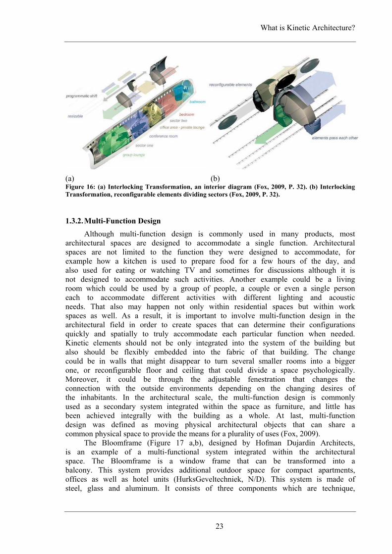
What is Kinetic Architecture?
23
(a) (b) Figure 16: (a) Interlocking Transformation, an interior diagram (Fox, 2009, P. 32). (b) Interlocking
Transformation, reconfigurable elements dividing sectors (Fox, 2009, P. 32).
1.3.2. Multi-Function Design
Although multi-function design is commonly used in many products, most architectural spaces are designed to accommodate a single function. Architectural spaces are not limited to the function they were designed to accommodate, for example how a kitchen is used to prepare food for a few hours of the day, and also used for eating or watching TV and sometimes for discussions although it is not designed to accommodate such activities. Another example could be a living room which could be used by a group of people, a couple or even a single person each to accommodate different activities with different lighting and acoustic needs. That also may happen not only within residential spaces but within work spaces as well. As a result, it is important to involve multi-function design in the architectural field in order to create spaces that can determine their configurations quickly and spatially to truly accommodate each particular function when needed. Kinetic elements should not be only integrated into the system of the building but also should be flexibly embedded into the fabric of that building. The change could be in walls that might disappear to turn several smaller rooms into a bigger one, or reconfigurable floor and ceiling that could divide a space psychologically. Moreover, it could be through the adjustable fenestration that changes the connection with the outside environments depending on the changing desires of the inhabitants. In the architectural scale, the multi-function design is commonly used as a secondary system integrated within the space as furniture, and little has been achieved integrally with the building as a whole. At last, multi-function design was defined as moving physical architectural objects that can share a common physical space to provide the means for a plurality of uses (Fox, 2009).
The Bloomframe (Figure 17 a,b), designed by Hofman Dujardin Architects, is an example of a multi-functional system integrated within the architectural space. The Bloomframe is a window frame that can be transformed into a balcony. This system provides additional outdoor space for compact apartments, offices as well as hotel units (HurksGeveltechniek, N/D). This system is made of steel, glass and aluminum. It consists of three components which are technique,

Chapter One
24
frame and electronic control. The size, materials and color can be changed upon request, although the maximum width is 3 meters. The façade element can be produced in several transparent and opaque materials. This system can be installed to new as well as existing facades. The Bloomframe can be automatically operated and single control that can open it in just 15 seconds. To achieve maximum safety and security requirements, the system includes provisions to guarantee against collapse during opening and closing, the fully open position is limited mechanically, and an optional infrared detection during electrical movements is installed. The first models are for an apartment building in Arnhem , The Netherlands (Brownell, 2008).
(a) (b) Figure 17: The Bloomframe (HurksGeveltechniek, N/D). (a) In window state. (b) In balcony state.
The turn-on house, designed by the Austrian design studio Alles Wird Gut
in 2002, is an example of the multi-function design (Figure 18 a,b). This design is tracking the idea of astronauts' capsules. The turn-on house is divided into individual ring zones that could be connected to each other and that accommodate different functions. By rotating these ring zones different needs could be achieved according to the users' needs, for example, in a kitchen ring unit a stove could be rotated up and out of the way when not used, or a sofa and a bed could be built into the same ring unit also rotated according to what is needed (Kapfinger, N/D).
(a) (b) Figure 18: (a) A diagram shows different ring units connected to each other while in use (Kapfinger,
N/D). (b) A ring unit (Serrats, 2005, P. 380).

What is Kinetic Architecture?
25
1.3.3. Contextual Adaptability
Contextual issues in architecture are categorized into three areas: form (space, shape, scale, and materials), activity patterns, and climatic patterns. Contextual adaptability will focus upon form and climatic patterns as activity patterns have been considered in spatial optimization systems and multi-function design. Architects are skilled and intelligent in developing solutions for contextual response and flexible adaptability, yet they rarely combine the two into a single system within buildings. As contextual architecture confirms the continuity of the present with the past while rarely considering the future, buildings should have the built-in life-cycle ability to adapt to long-term changes that occur over time such as changes in the built environment, traffic patterns, wind currents, etc. Natural environments should be considered in buildings equal to the architecture of historic buildings already present in an area through a comprehensive contextual approach. The aim of contextual adaptability is creating buildings that can deal with changes in site conditions that occur beyond codes and regulations and through flexibility built into the architecture itself.
The Wind Veil, by Ned Kahn, is 79.248 meter (260 feet) long by 6 storey tall façade for the largest parking garage in Charlotte, North Carolina, USA (Figure 19 a,b). This dynamic façade consists of 80000 small aluminum panels that are hinged to move freely in the wind (Kahn, 2000). The façade transforms the invisible wind waves into visible metallic grass waves. On the other hand, these waves create never ending patterns of light and shade inside the building. This system was designed to provide ventilation and shade for the interior of the parking building (Margolis, 2008).
(a) (b) Figure 19: (a) An exterior view for the Wind Veil (Kahn, 2000). (b) A close view for the aluminum
panels of the Wind Veil (Kahn, 2000)
The convertible umbrellas for the courts of the Prophet's Holy Mosque in
El-Madinah, Kingdom of Saudi Arabia (K.S.A), are an example for the contextual adaptability. These twelve 17x18 m umbrellas are used as a convertible shade roof for the two large inner courts of the mosque. They are designed to blend in harmoniously with the traditional stone architecture of the mosque. These

Chapter One
26
umbrellas created a translucent vault spanning between the columns and the arcades surrounding the courts, thus making for clear and expansive spaces. These convertible umbrellas are designed in consideration of the extreme seasonal changes in climate so that the internal climate of the building could be radically influenced and at mean time keeping the energy consumption to a minimum (Figure 20 a,b). The opening and closing of these structures are controlled by computer systems that recalculate different factors such as seasons, sun position, external temperature, wind speed, and clouds (SL-RASCH-GMPH, N/D, Addis, 1997).
(a) (b) Figure 20: Convertible umbrellas for the courts of the Prophet's Holy Mosque in an opened and
closed state (SL-RASCH-GMPH, N/D).
The Bengt Sjostrom/Starlight Theater (Figure 21 a, b and c), designed by
Studio Gang Architects and completed in 2003, is another example of the contextual adaptability. This building was designed to replace a popular outdoor venue by ensuring the proceeding of the shows that took place within the building regardless of the weather as well as maintaining the open-air atmosphere. The roof created an origami-like transformable element that looked like a flower petals, and consisted of six identical triangular panels hinged along the bottom edge (StudioGangArchitects, N/D, Galindo, 2005).
(a) (b) (c) Figure 21: The Bengt Sjostrom/Starlight Theater. Study model shows the building's roof
(mnartists.org, N/D) while: (a) opened and (b) closed. (d) An inner view for the kinetic roof while
opened (Galindo, 2005, P. 78).

What is Kinetic Architecture?
27
1.3.4. Mobility
Since old days people used mobile buildings to move from place to another to follow food or due to seasonal changes. Nowadays, such buildings are being used for political as well as climatic reasons. Although mobile architecture is used in wars for encampments and hospitals, it is also used for world expositions, concerts, and street fairs where function is greatly needed. Mobile buildings are characterized by their ability to be easily constructed, deconstructed, moved from place to place, reassembled, and stored. Mobile architecture can take on a variety of scales that range from entire buildings to small single person enclosures. Lighting, thermal performance, acoustics as well as waterproofing are factors that determine the mobile building life-cycle, and while considering such factors unknowns in temporary locations could be easily and quickly adapted to. Mobile architecture is also designed and implemented for a diverse range of life-cycles, which has implications on everything from materials to connections and ultimately the costs. Some projects are designed as an alternative to the financial problems of fixed living such as high land prices. Others are designed as emergency residence. Even hotels are being designed to be mobile with rooms that can be taken or delivered to remote or urban locations such as campgrounds, festivals, and the like (Urbanist, 2007).
The Mobile Dwelling Unit (MDU) (Figure 22 and Figure 23 a,b) is an example of mobility. it was designed by LOT-EK in 2002. This mobile unit is a container that acts as a space to live, work or even store. Cuts in the metal walls of the container allow for extruded sub-volumes that contain different facilities. When these sub-volumes are pushed out from the sides, they free up the inner space creating a general living area. When they are pushed in, they fill the entire container, interlocking with each other and leaving the container's outer skin flush to allow worldwide standardized shipping. The MDUs were not only designed as individual units but also as ever changing colonies when gathered (LOT-EK, N/D, Kronenburg, 2008)
Figure 22: Mobile Dwelling Unit, the container plan while sub-volumes pushed out (fabprefab, N/D).

Chapter One
28
(a) (b) Figure 23: Mobile Dwelling Unit. (a) An exterior view while MDU in an opened state (Gardiner, 2003,
P. 132). (b) An exterior view while the MDU in a closed state (Block, 2011).
1.4. Summary
From all definitions mentioned above, the term "Kinetic Architecture" can be explained as buildings or building parts that act in response to surrounding changes whether these changes are in/out doors as well as environmental/human.
Although the first formal definition for the term "Kinetic Architecture" was in 1970, many kinetic solutions that varied from building components to building as whole existed. The use of kinetics was for different reasons such as protective (bridges), entertaining (stages and revolving restaurants), medical (sanatorium and solarium), and residential.
Kinetic trends in architectural environments currently address pragmatic or humanistic conditions or even both, and are divided into four categories:
i. Spatial optimization systems ii. Multi-function design
iii. Contextual adaptability iv. Mobility

CHAPTER TWO: KINETIC DESIGN KEY ELEMENTS


Kinetic Design Key Elements
31
2. KINETIC DESIGN
This chapter "Kinetic Design Key Elements" will cover the main three principles in kinetic design which are structural innovation and materials advancement, embedded computation, and at last adaptable architecture. Each of these principles will be explained separately, listing its main points and supporting it with examples.
2.1. Kinetic Design Key Elements
To go through intelligent kinetic design in architecture, some general mechanical and technological principles should be mentioned and explained. These principles are divided into three general categories which are: structural innovation and materials advancement, embedded computation, and recently adaptable architecture.
2.1.1. Structural Innovation and Materials Advancement
In developing kinetic systems, dealing with structures should not be independently but rather as a part of the whole system. For best structural solutions, ways and means are highly considered. The ways of kinetic structural solutions may include folding, sliding, expanding, and transforming in both size and shape, among others. While the means of kinetic structural solutions may include pneumatic, chemical, magnetic, natural or mechanical means (Fox, 1999).
As a result of recent technological innovation, manufacturing technologies have evolved to the degree where creating intelligent kinetic architectural solutions became effective and feasible. These kinetic systems depend upon advanced computer control technology as well as high quality manufactured kinetic parts. New materials may include ceramics, polymers and gels, fabrics, metal compounds and composites, nano materials, and plastics, which can help creating highly intelligent responsive kinetic systems. Developing materials technology helped in facilitating creative solutions not only for kinetic structural systems but also for membrane systems, tensegrity systems, as well as thermal and acoustic systems.
Kinetic Structures Typologies
Kinetic structures are classified into three main categories, which are embedded, deployable, and dynamic kinetic structures (Figure 24). Figure 24: Diagram shows kinetic structures typologies (Fox, N/D).

Chapter Two
32
a. Embedded Kinetic Structures
Embedded kinetic structures are defined by Michael A. Fox as "systems that exist within a larger architectural whole in a fixed location". The main function is controlling the architectural system as a whole in response to changing factors such as environmental changes especially seismic and wind conditions. Embedded kinetic structures are the most developed of the three categories and are always coupled with computational control.
The Muscles Tower is an example of embedded kinetic structures that could be installed in a larger architectural whole. The project was the winner of the MIT's first mini-skyscraper competition in 2006 (Figure 25 a). The Muscles Tower is a 35 feet skyscraper consisting of an articulated spine controlled by a series of pneumatic muscles that allow the structure to bend in different directions by twisting the jointed core. When the muscles are not active, the tower's rigid core keeps the entire structure straight. By activating several muscles one could cause the tower to curve making it appear to bow. In a full-scale tower, such systems could help stabilize the structure against changing forces such as wind and earthquakes (Than, 2006, Plan65, 2006).
(a) (b) Figure 25: (a) The Muscles Tower while activated (Detwiler, 2006). (b)The Carlos Moseley Music
Pavilion while being transported to its location and being assembled (Mota, 2007).

Kinetic Design Key Elements
33
b. Deployable Kinetic Structures
While embedded kinetic structures are fixed in their locations, deployable kinetic structures are described by Michael A. Fox as "structures that typically exist in a temporary location and are easily transportable". These systems are characterized by their ability of being constructed and deconstructed in reverse which afford mobility rather than motion within a fixed structure. They are commonly used in exhibit design as well as pavilion and stage design which are driven by the need to be easily and quickly assembled and disassembled. Unlike embedded kinetic structures, deployable kinetic structures are rarely coupled with computational control.
The Carlos Moseley Music Pavilion is a state-of-the-art performance facility that creates an example for a deployable kinetic structure (Figure 25 b). The design of the Carlos Moseley Music Pavilion allows the structure to be easily constructed and deconstructed, then moved to the next performance location. The pavilion consists of seven semi-trucks that carry the entire facility to any open site. One trailer is for the stage and rear truss, two trailers are for the structural trusses, one truck for the fabric and lighting, one trailer for sound towers, one truck for electrical distribution, and the last truck for props. The centre trailer contains folding beams when opened; it provides a structure for the stage. On the same trailer, hydraulic pistons unfold hinged panels that serve as the stage surface. In its final position, the stage rests upon the two front corner trailers and the two rear corner cabs, and the entire assembly is joined together to form one continuous rigid structure(FTL, N/D, Addis, 1997).
c. Dynamic Kinetic Structures
"Dynamic kinetic structures exist within a larger architectural whole but act independently with respect to control of the larger context" (Fox & Kemp 2009). Dynamic systems are the most commonly used of the three listed categories. They include small architectural elements as well as large ones, such as doors, windows, movable partitions, furniture, and ceilings. As they act independently, it is quite common to have dynamic kinetic systems within a building that has an embedded kinetic system as well. They are becoming increasingly automated and intelligent as a result of the technological innovation nowadays.
Dynamic kinetic systems are sub-categorized into: i. Mobile systems: are those that could be physically moved within an
architectural space to different locations. ii. Transformable systems: are those capable of changing shape to take on
a different spatial configuration and can be used for space-saving or utilitarian needs.
iii. Incremental kinetic systems: are those that can be added to or subtracted from a building like LEGO pieces (Fox & Kemp 2009).
The Flare-façade system is a modular dynamic system that can be installed
on building's façades or any wall surface. This system creates a living skin allowing the building to express, communicate and interact with its environments (WHITEvoid, N/D). The Flare-façade system consists of a number of tiltable metal flake bodies. These units are controlled by computer to form any kind of

Chapter Two
34
surface animation. Sensor systems inside and outside the building communicate the buildings activity directly to the Flare-system which acts as the building lateral line. Each of the units reflects the bright sky or sunlight when in vertical standby position. On the other hand, when it is tilted downwards, its face is shaded from the sky light and appears darker (Jiang, 2011).
(a) (b)
Figure 26: (a) Two of the modular units of the Flare-façade system and their control mechanism
(WHITEvoid, N/D). (b) A paper model for the Flare-façade system (WHITEvoid, N/D).
The Kuwait Pavilion for the Expo 92 in Seville, Spain, by Santiago Calatrava is an example of dynamic kinetic structures (Figure 27). The structure's roof reflects the organic shapes of palm fronds that can be moved to reflect the weather or time of a day. Sketches drawn by Calatrava showed two hands coming closer to each other then folding together as in prayer creating a rare theme of offering hands and linking of fingers (Harris, 2006, Feuerstein, 2002).
Figure 27: The Kuwait Pavilion for Expo 92 while changing from closed state to opened one (Hawarny,
2008, P. 30).
2.1.2. Embedded Computation
As Guy Nordenson mentioned, "A kinetic environment without the computation is like a body without a brain – incapable of moving". In this statement, computation is the brain that can control the required change and motion. Users and inhabitants of architectural space can have environments that change and adapt according to information gathered by means of computation and sensing technologies. This is the importance of kinetics as well as embedded computation. The importance of embedded computation is not only for the ability to sense change in the environment but also for its ability to control the response to this change. Embedded computation is the combination of computational processors and information gatherers such as sensors, cameras, and microphones.

Kinetic Design Key Elements
35
2.1.2.1. Trends in Embedded Computation
Ubiquitous computation is the combination of embedding hardware and software, information processors and coded intelligence. Creating networks of information and computers is the trigger behind the development of computational devices. The wireless architectural world is becoming cheap, effective, and standardized. Architectural projects that involve embedded computation range from being purely pragmatic environmentally responsive to adaptive intelligence that understands human behaviors. Trends in embedded computation consist of four categories:
a. Active Control Research
Active control is the most applicable research in designing intelligent systems that focus on modifying the structural behavior depending on the changing demands. Changing variables in buildings may include wind loads, seismic conditions, temperature, light and live mechanical loads. Active control systems are defined as structures that are affected by an externally activated device to change the response. In these systems sensors are used for measurements and computers are used to activate the required external force by digital signals. Active control research is a system that solves purely pragmatic although often unpredictable environmental changes (Fox & Kemp 2009).
Such systems have successfully been installed in many buildings that are located in high wind or earthquake-prone locations. Active control technology includes seismic base isolation systems, passive (tuned) mass dampers and energy dissipation devices for buildings and other structures, and seismic floor isolation systems for critical spaces that house computers or medical equipments. Such systems employ numerous members to provide control through a very specific response for suppressing forces either by cables used as active tendons or by hydraulics used as muscles (Fox & Kemp 2009).
The Taipei 101 building is an example for such active control research systems. It consists of 101 floors above the ground and 5 floors underground. It is 508m height from the ground to the structural top. The tower has the world's largest passive tuned mass wind damper that is 5.5 meters in diameter and weights 660 metric tons (Figure 28 a). The Tuned Mass Damper (TMD) is designed to reduce the wind movement in the building. The TMD is located between the 87th level and the 92nd floor (Figure 28 b) (Taipei101, N/D).
(a) (b) Figure 28: (a) An interior view for Taipei 101 tuned mass damper (TMD) (Wikipedia, N/D). (b) A
diagrame shows where the Tuned Mass Damper is located in Taipei 101 Building (Wikipedia, N/D).

Chapter Two
36
b. Adaptive control
Adaptive control system is computer controlled automation whereby an architectural control system actually programs itself through observing both the user needs and changing environmental conditions. These systems have the ability to learn what the best preference is in just three or four user settings. Such systems can respond to many environmental conditions by installing temperature detectors or thermostats. For example, on cold days heating systems will switch on preventing pipes from freezing, and on hot days motorized windows will open. Also, scheduled timed programs can be used such as switching the heating or air conditioning on and off, controlling the thermostat, or operating garden sprinklers on regular times.
Adaptive control is highly developed in manufacturing industries although recent applications are based on users' behavior within a home environment. Adaptive control used in buildings can range from fire safety to security system solutions to energy efficiency. Such systems that are able to learn how to adapt will make buildings more comfortable, safe, productive, efficient and therefore less costly to operate while at the same time minimizing errors. These systems help a contently growing dialogue to take place between the space and its users.
The Implant Matrix is an example for adaptive control systems (Figure 29). This matrix acts as an interactive geotextile. This system is capable of mechanical empathy and consists of a network of mechanisms that reacts to human occupants. The system responds to human presence by subtle grasping and sucking motions, ingesting organic materials and incorporating them into a new hybrid entity. The matrix's interactive systems employ capacitance sensors, shape-memory alloy wire actuators and distributed microprocessors. The Implant Matrix is installed at the InterAccess Media Arts Center in Toronto (PhilipBeesleyArchitectInc., N/D).
Figure 29: The Implant Matrix (InteractiveArchitecture.org, 2006).
c. Home Automation
Home automation systems are systems that focus on changes in human action, adapt to how they use architectural space, and respond to their behaviors. Home automation systems have become robust and affordable enough to reach a general public audience. These systems are fully automated and deal with all

hothtophthsu
coacsyspasteinsy
hothsyhosymlik
Fi
inpoexsydeobofinacex
ome systemhe near futo uncommohone. Theshat an acubsystems.
Althouomputation ccessible. Dystems to pace. Althos their desechnical exnterface thaystem.
The Aome automhat offers ystems. Thome, from ystem. The
mechanical ke (AMX, N
igure 30: The
d. Exte
Externanformation ossible for xperienced ystems begevices, exbjects remof mobile tn a wirelectivities wxternal com
ms that ranture, home on and dase systems ction by
gh home is becom
Devices susense and
ough homesires, they xpertise to at makes i
AMX Whomation syste
homeownerhis system
where ho AMX Whdevices su
N/D).
e AMX Whol
ernal Comm
al communis being r
architectunot only
gan to takxternal comotely havetechnology ess way. ithin the mmunicatio
nge from automatio
angerous slink all
the owne
automationming more
uch as send detect ce owners u
purchase install. T
it easier f
ole Home ems. The Ars the abi
has a toomeowners hole Home
uch as aud
le Home Auto
munication
nication syremotely inural environ
within thke place ommunicatio
e changed. helped u
These sysspace, as
on systems
lighting, con systems situations bindividual
er can c
n systems simplified
nsors and changes in understand not system
These devifor an ord
AutomatioAMX Whoility to couch panel can opera
e Automatidio and vi
omation touc
n
ystems allonputted intonments to e space boutside theon started.
The techusers to costems mak
well as s evolve
37
climate, to will allow
by email systems i
ause man
are becoand afforcameras human a
their homms but indi
ces are coinary hom
on (Figure ole Home ontrol and
connectedate, controlion system ideo device
h panel (AM
ow local ao the syste
be interacbut also bee space an. Since
hnological ommunicateke it poss
people usrobotic sy
Kinetic
security aw the hom
or text-bain a single
ny sub-act
oming soprdable and are used
actions witme and its
ividual devonnected te user to
30) is aAutomationmanage w
d to all o, program,
controls ees, lighting
MX, N/D).
automation em. Such sctively vieeyond its nd was cothen methadvancemee informatsible to ising the system con
c Design Ke
and entertame to alert ased messae home toions acros
histicated, hence co
in home thin the a
deficiencievices that to a self-e
set and c
an examplen is a sinwide rangeother system and re-prelectronic g, openings
to take psystems wiwed, contrwalls. Wh
onnected thods of nts and ation acrossinfluence space. Prontrolled th
ey Elements
ainment. Inits owner
ages on aogether, soss several
embeddedmmerciallyautomationrchitecturales as wellneed little
explanatorycontrol the
e of suchgle system
e of homems in therogram theas well ass, and the
place whileill make itrolled, andhen wiringto externalcontrolling
affordabilitys networksthe space,
ojects withhrough the
s
n r a o l
d y n l l e y e
h m e e e s e
e t d g l g y s ,
h e

Chapter Two
38
World Wide Web (WWW) and a live camera that allow the controller to view manipulations. Although the technology and software of messages became more sophisticated, logging in and playing rudimentary games with the building and against each other became possible.
The Stereoscope (Figure 31) is the latest Blinkenlights project and an example for an external communication system. In this project, Toronto City Hall works as an interactive three dimensional computer display. Wireless technologies are used to control the lights placed behind the 960 windows of City Hall which allow for a large scale visual concert during the night. People can interact with the building by playing classic computer games on the façade while using a mobile phone. Also a simple animation tool and an open animation data formats enable people to create simple movies for Stereoscope and then play those on the façade (ProjectBlinkenlights, N/D).
Figure 31: The Stereoscope Project while
playing an animation on Toronto City Hall
façade (AlternativeBerlin, 2010).
2.1.2.2. Level of Control Mechanisms
As kinetic in the architectural context is the application of objects which could be set in motion by having mechanical parts, several levels of machines may exist simultaneously in different kinetic architecture typologies. Computer controlled systems help observing the users' needs as well as the changing environmental conditions by reprogramming themselves as they learn what the perfect setting for each condition is. Many examples of such systems could be found in the area of "Home Automation". And it may include systems that control heating or air conditioning, lighting, garden sprinklers, and motorized openings. These systems could act independently or as a part of a whole by operating co-operatively to optimize conditions (Fox, 2009). Levels of machines could be listed by their ability to adapt to different needs as:
a. Singly variable-man control
Singly variable man control was the first category developed by man, which was the extension of the tool which in turn was extension of the hand. This category of machines was designed to perform a repetitive operation. Increasing and decreasing speed as well as starting and stopping of these machines were done by human control and in some machines even the motive power was supplied by humans (Zuk, 1970).
Kinetic Design Key Elements
39
b. Multivariable-man control
This category of machines was more developed than the first one not only by their complexity degree but also by their ability to perform several functions in sequence or simultaneously, although they were still controlled by humans (Zuk, 1970).
c. Multivariable automatic control
These machines differ by their ability of partial or full control of multivariable operations. Sensors are essential in this category of machines which help in detecting different tangible and intangible factors such as velocity, acceleration, light, heat, pressure, odor, sound, radiation, weight, voltage, current, magnetism, length, and size. In this category computers replace the human functions by carrying out only those specific instructions and operations early predicted by human programmer in anticipation of certain specific data and reactions. These computer controls are coupled with backup systems or human control ability for emergencies (Zuk, 1970).
d. Multivariable heuristic control
Technology, computers, and the science of cybernetics that deals with man-made systems performing functions like those of a human brain have become more developed. As a result, creating computers and systems that are capable of learning from their previous actions and experiences become more reasonable. In this category, machines are not only multivariable and automatically controlled but also coupled with heuristic and learning capability. This kind of machines is well known as "Robot Machines". This type is developed to perform adaption, ranging from machines that construct whole buildings automatically and completely to those that repair and reproduce themselves automatically (Zuk, 1970).
2.1.2.3. Ways and Means of Embedded Computation
The relationship between users and programmable embedded intelligence ultimately dictates the intensity of the ever changing dialogue between bodies in space and the space itself. Understanding the behavior of an architectural space or object will make it possible to not only monitor but also control environments even remotely. Ways and means are defined as the controlled source of actuation addressing embedded computation that controls mechanism for kinetic function which accommodates and responds to changing demands. These systems are used to interpret functional circumstances and direct physical movements and data sets in order to suit changing demands and needs.
Controlling kinetic motion is affected by design and construction techniques, kinetic operability and maintenance, as well as human and environmental interaction. Embedded computation in the materials that make up the space allows users to control the type of information the space receives through communication methods similar to those used to communicate with people. While designing interactive kinetic architecture, the structure of the

Chapter Two
40
information hierarchy that governs the relationship between users and space must be considered. Sensors technology is one of the most important means that are used to actively control kinetic objects in the built environment in response to change.
a. Sensors
Sensors are devices that gather information from the real physical environments such as light, motion, temperature …etc. They have dramatically developed from the most simple being an invisible infrared beam that is broken to detect motion to more sophisticated ones that can detect color definition, motion directionality, voice and facial characteristics, gain …etc. More detailed information is provided when combining sensors with processing software to track bodily movements, which will help providing information of individual users' behaviors to the building. Web cams and other optical input devices as well as conventional sound/text input devices are used as means of gathering information.
2.1.2.4. Typologies of Controlling Change
It is important to consider the amount of information dialogue between users and computation. Understanding the possible relationship between computation and response will help controlling the desired change. Creating subsystems that act independently can be incorporated into kinetic design (Fox, 2009). Means of controlling space are categorized into five general types:
a. Direct Control
In this type of controlling change the information is directly translated into an outcome. Direct control involves an information exchange that is usually an "on" or "off" state. The movement is actuated directly by any of numerous energy sources including electrical motors, human energy or biomechanical change in response to an adjacent exchange of information between users and the computer.
b. In-Direct Control
This type of controlling change involves a level of decision making embedded into the system itself. In-direct control systems depends on a sensor to detect change and then send a message to a control device which in return relays an on/off operating instruction to an energy source for the actuation of movement. This controlling system has the ability to both constantly monitor incoming information and update the response of the system.
c. Responsive In-Direct Control
The difference between in-direct control and responsive in-direct control systems is that in the second one the control device receives input information from numerous sensors and then makes an optimized decision to send to the
Kinetic Design Key Elements
41
energy source for the actuation of movement for a singular object. This system requires a governing hierarchical computational system to interpret information from multiple sources and act accordingly.
d. Ubiquitous Responsive In-Direct Control
This system depends on many autonomous sensor/motor (actuator) pairs acting together as a networked whole to actuate movement.
e. Heuristic Responsive In-Direct Control
This system differs from responsive in-direct control and ubiquitous in-direct control systems with its ability to learn through successful experiential adaptation to optimize a system in an environment in response to change. The computation that is embedded in a system can be written or programmed in a way that can build upon the system's prior experiences. This is achieved by rewriting previous methods of making decisions. An example could be a skylight system that records the weather patterns and associates behavior patterns while being operated. Such a system can use gathered information to respond accurately to changing climate patterns while learning the most efficient response for individual parts the system consists of. Connecting this system to other intelligent systems in the building will achieve similar goals.
2.1.3. Adaptable Architecture
Kinetic architecture is built on both embedded computation (intelligence) and the physical counterpart (structural engineering and kinetics), which satisfies adaptation within human and environmental interaction. The combination of these two areas will make it possible for any environment to reconfigure itself, to automate physical change, to respond, react, adapt, and interact. Adaptability is defined as the flexibility of space to face changing demands on the system. Adaptability in built projects was either embedded in the logic of the creation of a system such as manually adjustable modular panels and structure systems by Fuller, or embedded in the logic of the kinematics such as manually adjustable awnings and domes by Calatrava and Hoberman.
Past kinetic projects were adaptable although they relied on their user to manually change the size, color, shape, or location of an object that made up the space in respect to the new demands. The difference between those past kinetic projects and new ones is that in new projects spaces are being interactive with their ability to sense information from the users or the environment and then adapt themselves. Adaptable architecture may range from interior organizational disposition to external environmental mediation to complete structure transformability/transformation. Adaptable architecture is divided into four categories which are living, working, entertainment, and public environments.
Chapter Two
42
2.1.3.1. Living Environments
Interface design is important as a way in which users interact in a living environment. A keyboard is a primary device for inputting data, but that is going to change when environments are ubiquitously gathering and receiving data via sensors, cameras, microphones, and the like. Personal information is always needed in living environments. There is a direct relationship between the amount of information a system can gather and the usefulness of that system. Privacy becomes a major issue according to the balance between the gathered information and the amount of privacy one has to give up. Home automation systems are the most developed area of living environments. These systems are fully automated and are capable of controlling all systems in a home such as lighting, climate, security, and entertainment. The user is able share information with one or more users, either in the same location or in remote ones, which can be made feasible via video-conferencing. In all those possible links, the privacy level can be controlled by simply turning off the connection to others whenever needed (Fox, 2009).
2.1.3.2. Working Environments
Many work environments are being constantly changed by upsizing and downsizing the space according to the number of occupants needed for the commissioned work. Desks and worktables are being moved around to make room for the additional number of employees needed, or are being moved back after the work is done. For weekly meetings, a large conference room set for fourteen to twenty users is needed, and yet for all other meetings the room may only be used by four to six users at a time. Also, some office spaces are being used sporadically during the day. For instance, a person's desk - while not in use - may be transformed to be used by another person while satisfying the specific needs of its new user such as lighting, privacy, acoustics ...etc. Another example could be the conference rooms, which are either able to reconfigure themselves or manually being reconfigured according to the number of users and their needs. An interactive kinetic work environment can also deal with all of the peripheral needs for spatial optimization that go beyond the effective usage of space to include lighting, wiring, acoustics, privacy, and view (Fox, 2009).
2.1.3.3. Entertainment Environments
Entertainment environments that embrace interactivity either provide leisure, social engagement, or educational benefits. In order to capture an audience, elements that adopt interactivity such as sculpture, fountains, and building facades have been enormously used. Museums, as entertainment environments, have adopted interactivity in presenting and viewing exhibits and artifacts. Collaboration between interactivity and adaptability can positively affect the temporal nature of changing displays and the way visitors interact with those. Most entertainment applications include educational elements in which a kinesthetic learning is combined with entertainment experiences. These environments enable users to utilize both their bodies and minds in collaborative ways. Edutainment is a commonly used term for such entertainment environments that are designed to equally educate and amuse (Fox, 2009).

Kinetic Design Key Elements
43
2.1.3.4. Public Environments
Interactive adaptive systems can be employed immensely in the public sphere. Also, achieving commercial benefits through specific consumer trends instead of individual basis is an important point in designing such public systems. Moreover, the interactive adaptive design in the public sphere engages both the social and cultural dimensions of space. Spatial defining interaction is commonly used as a mechanism to understand and promote social interaction. The physical architecture can be used to include or exclude people from one another, to facilitate, dissipate, or focus crowds of people. Public environments are used in testing both the durability of materials and the time frame of particular interactive strategies within the context of unpredictable participants. For example, commercial outlets and grocery stores could make an active inventory that moves itself to the forefront to either target a particular customer or show specific items when they are more desirable during parts of the day. Restaurants as well could use all of their seating more efficiently rather than seating a party of two at a table designed for four (Fox, 2009).
The Interactive Restaurant (i-Dining) project (Figure 32) by Art Center College of design is an example of such environments. This project consists of six major systems which are floorscape, ceilingscape, tables, vanity/façade, acoustics (walls), and bar. Each of these systems aims to create an environment with behaviors. The floorscape aims to create constantly evolving and forming groups of any size or shape or number of users. In that case the seating is one element that will influence other systems to further interact with customers (RobotectureInteractiveArchitecture, N/D).
Figure 32: The Interactive Restaurant (RobotectureInteractiveArchitecture, N/D)

Chapter Two
44
2.2. Summary
From all mentioned above, it is important to mention and explain the mechanical and technological principals to go through kinetic design. There are three key elements that kinetic design is based upon. The table below briefly lists these three key elements and the main points in each (Table 1).
Table 1: Kinetic Design Key Elements.
Kinetic Design Key Elements
Structural Innovation &
Materials Advancement Embedded Computation Adaptable Architecture
Ways & Means of Structural Solutions
Ways: folding, sliding, expanding, or transforming
Trends in Embedded
Computation
Active Control Research
Adaptive Architecture
Environments
Living Environments
Means: pneumatic, chemical, magnetic, natural or mechanical
Adaptive Control
Kinetic structures Typologies
Embedded Home Automation
Deployable External Communication
Dynamic
Levels of Control
Mechanisms
Single Variable-man Control
Working Environments
Multivariable-man Control Multivariable Automatic Control Multivariable Heuristic Control
Typologies of
Controlling Change
Direct Control Entertainment Environments In-Direct
Control Responsive In-Direct Control Ubiquitous responsive In-Direct Control
Public Environments
Heuristic Responsive In-Direct Control

CHAPTER THREE: KINETIC BUILDINGS' ANALYSIS


Kinetic Buildings' Analysis
47
3. KINETIC BUILDINGS' ANALYSIS
In the previous chapter kinetic design key elements are presented from structural innovation and materials advancement to embedded computation as well as adaptive architecture. In order to understand the different aspects of kinetic buildings, this chapter will attempt to analyze and evaluate different kinetic buildings. This evaluation will end up with a comparative analysis aiming at providing explanations on the different factors affecting the use of kineticism in buildings in their specific environments.
3.1. Architectural Projects:
From a large number of buildings that encompass kineticism, only fifteen buildings are selected. The selection of buildings is based on a set of criteria comprising the year of completion, buildings' use and type of kineticism they present. Buildings are selected among those completed from 1980 up till present. They are listed in chronological order. Also, they are selected to cover a wide range of uses that vary from multi-family housing, private houses, workplace and sports facilities. Moreover, buildings are selected to include different ways of dynamics that range from envelope dynamic elements, to indoors kinetic elements or even buildings that are able to be in motion as a whole.
The cumulative information and findings deducted from the previous chapter are used to establish a set of evaluation criteria. These criteria will assist in the analysis of kineticism in the selected buildings and therefore will help in formulating an understanding of the most suitable techniques and methods that can be used in the Egyptian environment. The evaluating criteria include the following:
a. Kineticism in the building: - Kinetic elements. - Reason for motion.
b. Kinetic design key elements which are presented by: - Structural system. - Used materials. - Embedded computation / control mechanism. - Adaptive architecture.
c. Building quality: - Indoor environment quality. - Building visual quality.

Chapter Three
48
3.1.1. Institut du Monde Arabe:
Figure 33: An external view for Institut du Monde Arabe (WikiArquitectura, 2010).
3.2.1.1. General Information:
a. Completion Year: Construction completed in 1987.
b. Architect: The project is designed by Jean Nouvel.
c. Building Cost: 47,500,000 USD (52,000,000 Euro) approximately.
d. Introduction:
Institut du Monde Arabe (Figure 33) is built in Paris, France. It is conceived as one of the new architectural landmarks of the capital. Situated in the center of the capital the building provides a meeting place for the two cultures which have produced it: France and twenty Arab countries. It provides a place for continuing artistic, technical and scientific exchange between two old civilizations which have continuously enriched each other.
In 1981 a site was selected for Institut du Monde Arabe. The site was allocated at the 15th arondissement, on rue de la Federation near the Boulevard Grenelle, located in a residential district not far from the Eiffel Tower. The residents of that neighborhood protested against building on a site that was used as a sports area. A first project had been prepared for that site for Institut du Monde Arabe and was designed by architect Henry Bernard.
Later a new site was selected at the 5th arondissement. Culturally and historically the new site had a higher value located on the oldest part of Paris and facing Notre-Dame. To encourage new architects a competition was held for a new project cancelling the old one and seven architects were invited. A pre-selection was made by an Evaluation Committee and the final selection was by the President Mitterand. The winning project was designed by Jean Nouvel (Yucel, 1989).

Kinetic Buildings' Analysis
49
e. Location:
The Institut du Monde Arabe is situated at the historical heart of Paris, France. The building site is surrounded by the Seine and St. Bernard quay on the north while facing l'Ile St. Louis and la Cite the old settlement of Lutece.
a. Concept:
In the Institut du Monde Arabe, Jean Nouvel used Mashrabiya units (Figure 34 a) to represent the Arabic culture. Mashrabiya is a type of a window cover that consists of combinations of backdrop of cut wood and latticework patterns (Figure 34 b). Mashrabiya characterized the Islamic architecture of the Middle Ages and was popular in many Islamic countries such as Egypt (Figure 34 b) and Iraq. The architect combined the need for sun shading with a "Mashrabiya" pattern and the idea of a light controlling diaphragm in a camera lens (Figure 35). This resulted in a gigantic Islamic pierced screen, which makes this modern high-tech building a permanent reference to traditional Islamic architecture (Heylighen, 2004).
(a) (b) (c) Figure 34: (a) The Mashrabiya diaphragm used at Institut du Monde Arabe (Osmers, 2007).
(b) Mashrabiya unit sketch (Prisse d’Avennes, 2007, P. 137). (c) Mashrabiya used in a Ottoman
residential building near Khan El-Khalili, Cairo, Egypt (a.allegretti, 2012).
Figure 35: An external view for the flat southern façade of Institut du Monde Arabe shows the
"Mashrabiya Diaphragms" that were used (IMA, 2001).

Chapter Three
50
b. Building Components:
The usable floor area was estimated to cover 13000 m2 and the whole built-up area 20000 m2, to be consisted of: • The Museum of Arab Art and Civilization (permanent and temporary
exhibition space). • The Library, Documentation Centre and Actualities Hall. • The Auditorium and Conference Hall. • The High Council Hall and related offices. • Hall. • Restaurant and Cafeteria. • Public services. • Other administrative, technical and service spaces including the parking area.
3.2.1.2. Kineticism in the Building:
a. Kinetic Elements:
The mashrabiya diaphragms (Figure 36 a) were influenced by the orientation and are aiming at aesthetic and connotative architectural expressions rather than solutions to climatic constraints in a high-tech air-conditioned building context. The flat southern facade is composed of 240 squares panels, reproducing vertically the horizontal pattern of the parvis. Constituted of 16320 kinetic modules, these diaphragms consist of lozenges, squares, hexagons, circles and combination of them whose reflection matches the mosaic patterns on the Institut's floors. Each kinetic panel consists of one large diaphragm in the center, surrounded by sixteen medium sized diaphragms and fifty-five small diaphragms (Figure 36 b,c).
(a) (b) (c) Figure 36: (a) A view for a group of the mashrabiya diaphragms while functioning (eliinbar, 2011). (b)
A detail of the medium sized diaphragm (moreAEdesign, 2010). (c) A detail of small diaphragms
(moreAEdesign, 2010).

Kinetic Buildings' Analysis
51
b. Reason for Motion:
The mashrabiya unites are functioning as diaphragms of a camera shutter. These metallic irises filter the sunlight through the glazed surface, allowing 10% to 30% of the light to be kept (Figure 37).
Figure 37: A diagram showing reason for installing mashrabiya diaphragms on the southern façade
(Yucel, 1989, P. 92).
3.2.1.3. Kinetic Design Key Elements:
a. Structural Innovation & Materials Advancement:
a.1. Structural Systems:
The structural system is a steel frame with different spans according to the general shape of the building. Steel columns, beams, trusses and secondary supporting elements for the curtain-wall facades were used.
a.2. Used Materials:
Stainless steel, aluminum, tempered glass, plastics, marble and finally the mashrabiya diaphragms.
b. Embedded Computation / Control Mechanism:
The kinetic southern façade of the institute is considered as a computer output device. All of the mashrabiya diaphragms are linked together and controlled by photo-voltaic cells that close or open them depending on the intensity of sunlight on that part of the façade. Users of the building can't interfere and/or control the diaphragms to change settings in their environment.
Da
yli
gh
t
10
%-3
0%
of
Da
yli
gh
t

Chapter Three
52
c. Adaptive Architecture:
This building is used as a cultural center that aims to introduce the Arab culture with all its rich historic and temporary dimensions, which creates an entertainment environment. Kinetic elements were installed in the building's southern façade in order to control light inside it. Those kinetic elements have the shape of "mashrabiya" which is an architectural element used in traditional Islamic architecture that are presented in a modern way that mixes history, tradition with science and technology. Although the kinetic façade doesn't interact with the building's users, it yet has an indirect educational benefit.
3.2.1.4. Indoor Environment Quality:
The stuff works in the building feels that transparent walls make privacy impossible. They feel enclosed in a small space with very low ceiling. All of them, librarians, museum keepers, and staff officers alike, feel they need more room for their projects. Although it appears large in photography, in fact, the building is small n size. Visitors and architects alike expect it to be larger than it actually is.
3.2.1.5. Building Visual Quality:
High technology is what holds the IMA together. The volumns are simple, giving forth a message of restraint, a restraint based on understated wealth. It is in the rich quality of its materials and its finish that the building shines. Glass shines, and the surfaces of aluminium shine. These shiny new qualities pervade the entire building, projecting a cool and perfect exterior façade. The IMA building appears to set a model for the Arab countries, not only in the technical field but also on the level of ideas, or golas to be achieved. No easy pastiche of Islamic motifs and designs is present in this building, no arches, no niches and no dames. The mashrabiyas are used to explore geometric patterns, and are extraordinary technological innovations. Even when Nouvel uses the essential Islamic architectural idea of hiding a rich interior behind blank walls, he totally transforms it. His exterior facades reflect the outside world, and bring them into the interior spaces. It may be a message indicating the way for the future of the Isalmic World.

Kinetic Buildings' Analysis
53
3.1.2. GucklHupf
Figure 38: An external view for GucklHupf while being opened (de la Torre, N/D).
3.2.2.1. General Information:
a. Completion Year: The GucklHupf was completed in 1993.
b. Architect: Building was designed by Hans Peter Wörndl.
c. Building Cost: No information available.
d. Introduction:
The building's name is related to the neighboring Guglhupfberg. The Gucklhupf (Figure 38) is a walk-in sculpture an exploration of architecture and art. It was built to mark "The Festival of the Regions" on a private lake property on Lake Mondsee. The theme of the festival was "The Stranger".
e. Location:
The GucklHupf was built on 1500 m2 of private grounds. The structure is surrounded by nature, at the Mondsee in Innerschwand / Upper Austria. Under public pressure the building is now removed from the site.
f. Concept:
As the theme of "The Festival of the Regions" was "The Stranger", the architect tried to create a relation between strangers and intimacy, relaxation and exercise as well as living and traveling. As a result, the out coming building was a structure that does not tend toward an absolutely final state but allows a progressive deviation from its initial state of stereometric object. The building is

Chapter Three
54
used by its owners during the six week long summer opening as a contemplative space, stage for small performances, music pieces and poetry readings with clear reference to the Arcadian myth. It is also being used as a house on the lake or as a temporary shelter during the rest of the year, while in winter it is transformed into a storage place for boats "boat-house".
g. Building Components:
The building consists of 2 floors (Figure 39). By moving the individual cube by half the storey height results in the interior of 4 different levels and a terrace on the roof (Figure 40). For the development of the upper floors a ladder was installed. The building is 7m height and the enclosed space is of 4m x 6m x 7m.
Figure 39: The GucklHupf plans where the red colored rectangular is the main area while the other
parts are those being opened, slided or folded (de la Torre, N/D).
Figure 40: The GucklHupf section where the red color indicates the accurate area when the structure
is closed. Also this section shows the four different levels inside the structure (Ballard Bell, 2006, P.
125).

Kinetic Buildings' Analysis
55
3.2.2.2. Kineticism in the Building:
a. Kinetic Elements:
The movable wood panels creating the GucklHupf can be rotated, pulled, tilted and folded. These wooden panels act as a wrapping that can be peeled away or pulled up to open and close the space according to its users desires.
b. Reason for Motion:
The GucklHupf movable panels create a multi-purpose structure. The structure is used as a lake house that can hold different activities from being a shelter in summer days to a contemplative space with a small stage or even as storage in winter days when closed (Figure 41). Also, the movable panels helped the users to control views and the amount of light according to their needs and desires. This transformation creates a communicative interior-exterior space object that provides a shaded, ventilated, temporary location in the landscape while controlling the level of connectivity with the nature and landscape around.
Figure 41: Transformation in GucklHupf starting from the closed state (Olson, 2009).

Chapter Three
56
3.2.2.3. Kinetic Design Key Elements:
a. Structural Innovation & Materials Advancement:
a.1. Structural Systems:
The building was constructed in frame construction, a frame construction consisting of a linear structural skeleton of squared timber and an outer cladding stabilizing the support frame is formed.
a.2. Used Materials:
Plywood, wood, aluminum, glass and silk screen printing.
b. Embedded Computation / Control Mechanism:
All moving parts of the GucklHupf are being controlled through an automated system that is comprised of automatic devices and retracing panels. This system is connected to the structure through dowels, flaps and stainless steel cables.
c. Adaptive Architecture:
The GucklHupf is a multi-purpose private property that creates an experimental living environment. The building is being used all year long, while its uses vary from being a lake house to a performances stage and storage.
3.2.2.4. Indoor Environment Quality:
When inside the structure, the user has the ability to edit and frame views of the surrounding landscape. The user has a control over their relationship with the surrounding landscape, while hiding within the protection of the small, contorting structure.
3.2.2.5. Building Visual Quality:
The Guklhupf guides the eyes and the movements of its inhabitants as everyone is free to choose a visual sequence and the number of openings, generating an intimate or visually permeable space. Externally, the facade re-creates the interior losing its role of wrapping skin. The structure creates a continuous relationship with its surrounding landscape as well as its users. The GucklHupf is in harmony with its surrounding even when not in use and close. The structure when closed looks like a large wooden box that was erected in the landscape. But once one begins to open the many wooden panels that can rotate in different directions, pull, tilt and fold: There are ramps, doors, windows, terraces and hatches (minimalspace, N/D).

Kinetic Buildings' Analysis
57
3.1.3. Floirac House "Maison à Bordeaux"
Figure 42: An exterior view for the Floirac House (OrgoneDesign, N/D).
3.2.3.1. General Information:
a. Completion Year: The house was designed in 1994-1996 and was built in 1996-1998.
b. Architect: The Floirac House is designed by Rem Koolhaas.
c. Building Cost: No information available.
d. Introduction:
This house was built for a wealthy publisher and his family whose dream was to have a simpler life. Dreams changed after a fatal car accident the husband barely survived and resulted in being confined to a wheel chair. Years later, the dream of having a new house was still there but this time with a new context. Simplicity was no more wanted, this time the client sought complexity to define his life. As a result, the Floirac House (Figure 42) was built as a monumental accommodation to this fact (Vanstphout, 2005).
e. Location:
The house is located on a hill overlooking Bordeaux, in France.
f. Concept:
The architect imagined the architectural potential in this family's life as a special case that differs from any other families. Rem Koolhaas imagined the lower body of the publisher with its whole arsenal of trusses, carts and belts for support as the architecture. The complexity of the building can be experienced immediately through the links between the different zones and levels, between inside and outside, and finally between the house and the city. There are several

Chapter Three
58
ways to go across the various zones and levels (Figure 43). Three staircases provoke the inhabitants to select their routes and an elevator platform located in the middle of the house "A machine is its heart" (Figure 44). The movement of the elevator platform continuously changes the architecture of the house. By creating a relation between small, private, painful and sad fact of the husband and the architecture of the house itself resulted in a beautiful place for living the Floirac House "Maison à Bordeaux".
Figure 43: Plans for the Floirac House showing different ways to access levels (Beck, N/D). The Blue
color indicates the elevator platform, the red color indicates the main staircase, the green color
indicates the service staircase and the yellow color indicates a staircase connecting two levels.
(a) (b) Figure 44: Long section though the Floirac House, where the blue color indicates the elevator platform
(Beck, N/D). (a) The elevator platform reaches the second floor. (b) The elevator platform is on the
ground floor.
g. Building Components:
The house consists of three floors. The lower level is a series of caverns carved out from the hill, designed for the most intimate life of the family; the ground floor on garden level is a glass room – half inside, half outside – for living; and the upper floor is divided into a children's and a parents' area (OMA, N/D).

Kinetic Buildings' Analysis
59
3.2.3.2. Kineticism in the Building:
a. Kinetic Elements:
The heart of the house is a 3x3.5m elevator platform (Figure 45) that moves freely up and down alongside a tall book-stack connecting the three levels together, while becoming part of the living space or kitchen or transforming itself into an intimate office space.
Figure 45: An isometric section showing the elevator platform in red (Beck, N/D).
a. Reason for Motion:
The elevator platform was designed to connect different levels together in an easy accessible way that allows the owner to move around as he is now confined to a wheelchair after surviving a car accident. The elevator platform was not only designed to function as a vertical connector but also to be a living space in the middle of the house (Figure 46). The platform grantees husband's access to books, art work and the wine cellar (Gargiani, 2008).
(a) (b) Figure 46: Different views for the elevator platform while functioning (OMA, N/D). (a) The elevator
platform when settled in the upper level. (b) The elevator platform while moving between different
levels.

Chapter Three
60
3.2.3.3. Kinetic Design Key Elements:
a. Structural Innovation & Materials Advancement:
a.1. Structural System:
Although the uppermost floor appears as if held down from floating away by a rod attached to large steel I-beam across its roof and anchored into the ground of the courtyard, this concrete box is supported in three places: the cylinder of the circular staircase, the L-shape structure that is propped by a steel stanchion rising from the kitchen below (Unwin, 2010).
a.2. Used Materials:
Concrete walls, panels of glass and aluminum were used for the exterior. Aluminum sheets were used for the flooring of the studio and the living area.
b. Embedded Computation / Control Mechanism:
The door that leads to narrow west part of the house is an electrically operated panel of metal opened by means of a large illuminated joystick alongside the courtyard. An embedded complex system including rail switches controls the movement of the large glass panels moving on floor-ceiling tracks, drapes, tapestries, curtains, paintings, lamps, doors and even a cave for doves. Same as other parts of the house, the elevator platform is controlled through a remote-control device.
c. Adaptive Architecture:
This house is considered as a living environment. The kinetic element installed in the structure which is the elevator platform in located in the house's centre. This elevator platform is not only a mean to connect different levels of the house, but also it is a work space for the wheel-chair bound.
3.2.3.4. Indoor Environment Quality:
The house appears to be living with its moving walls, lifting bedrooms, automated windows and platform allowing its handicapped owner a free accessibility to different levels (Gargiani, 2008). The narrow patio separating the two bedroom units allow for natural lightening. Layering opaque and transparent spaces provides for satisfying the needs for both community and privacy.
3.2.3.5. Building Visual Quality:
As the house takes place on the top of the hill, no colors were used that will make it visible from the valley of Bordeaux adding extra privacy. The lowest part of the house appears as a series of caverns carved out from the hill. Although the house looks like a space station waiting to be launched into orbit, it reveals a great connection with its surrounding landscape.
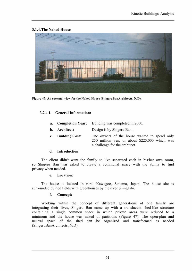
Kinetic Buildings' Analysis
61
3.1.4. The Naked House
Figure 47: An external view for the Naked House (ShigeruBanArchitects, N/D).
3.2.4.1. General Information:
a. Completion Year: Building was completed in 2000.
b. Architect: Design is by Shigeru Ban.
c. Building Cost: The owners of the house wanted to spend only 250 million yen, or about $225.000 which was a challenge for the architect.
d. Introduction:
The client didn't want the family to live separated each in his/her own room, so Shigeru Ban was asked to create a communal space with the ability to find privacy when needed.
e. Location:
The house is located in rural Kawagoe, Saitama, Japan. The house site is surrounded by rice fields with greenhouses by the river Shingashi.
f. Concept:
Working within the concept of different generations of one family are integrating their lives, Shigeru Ban came up with a translucent shed-like structure containing a single common space in which private areas were reduced to a minimum and the house was naked of partitions (Figure 47). The open-plan and neutral space of the shed can be organized and transformed as needed (ShigeruBanArchitects, N/D).

Chapter Three
62
g. Building Components:
The building consists of a simple, rectangular, shed-like space of two storey high and four cubicle mobile room units (Figure 48 a). The internal main space is bordered on one side by the kitchen, the bathroom and the wardrobes which are the only permanent installations in the house and are separated from the open space with a half-height wall or white curtains (Figure 48 b), while on the other side it is bordered by a translucent and opaque wall. Four movable cardboard boxes form the family's private accommodation (Jeska, 2008).
(a) (b) Figure 48: (a) A 3D modeling for the Naked House showing the rectangular open space, the permanent
installations as well as the movable rooms (boxes) (Unité-de-relogement, 2012). (b) An interior view for
the half-height wall separating the wardrobes as well as the bathroom from the rest of the open space
(Jeska, 2008, P. 73).
3.2.4.2. Kineticism in the Building:
a. Kinetic Elements:
In the Naked House, the cubical room units can be moved about on wheels to any location. The rooms can be moved around in different configurations. The character of the home's space can be dramatically reconfigured in a moment by moving the rooms around to create barriers or openings (Stang, 2005).
(a) (b) Figure 49: Interior views of the Naked House (van Poucke, 2011). (a) A view for mobile units when
attached to each other. (b) A view for mobile units arranged separately.

Kinetic Buildings' Analysis
63
b. Reason for Motion:
Kineticism was involved in the design in order to provide flexibility. Using movable rooms allowed residents to control privacy level as well as activities taking place within these rooms. These rooms can be grouped together or stay separated and the family can choose whether to sit inside or on the top, outside these rooms or in the main space. Also, they can be moved around the open spaced or moved to the outside (Guzowski, 2007).
3.2.4.3. Kinetic Design Key Elements:
a. Structural Innovation & Materials Advancement:
a.1. Structural System:
The design of the structure was basic with its double-height rectangular shell. The shell is made of wooden frame with corrugated plastic panels affixed to it (Figure 50 a).
a.2. Used Materials:
While the exterior walls are made of corrugated fiber-reinforced plastic panels, the interior is lined with nylon attached with Velcro strips. Clear plastic bags filled with polyethylene foam are used for insulation (Figure 50 b). The mobile units are made of paper honeycomb panels on timber frames (Bradbury, 2005)
(a) (b) Figure 50: (a) A section through the main double height open space (Bradbury, 2005, P. 185). (b) An
isometric for the Naked House showing different layer of the building's skin as well as different
components (Bradbury, 2005, P. 181).

Chapter Three
64
b. Embedded Computation / Control Mechanism:
The mobile room unites were manually moved around the house or pushed to the garden. No embedded computation systems were installed.
c. Adaptive Architecture:
Although the house itself is a living environment, the four mobile units create portable living environments within the main space. Those mobile living environments does not only may have different uses such as being a gathering place, sleeping place, playing place or even a garden shed, but also they may differ in size according to whether they are separately used or some/all of them gathered together (Figure 51 a).
(a) (b) Figure 51: (a) Different arrangements for the mobile room units (Guzowski, 2007, P. 2). (b) A close
view for the moveable units (Stang, 2005, P. 89).
3.2.4.4. Indoor Environment Quality:
The interior is lit by a soft, diffuse light filtering throw the translucent walls adding a sense of spaciousness. Sliding doors provided on two sides of each unit can be closed, left open or even totally removed (Figure 51 b)depending on the level of privacy needed and level of visual connection with the surroundings desired (Jeska, 2008).
3.2.4.5. Building Visual Quality:
The translucent walls for the naked house merge the indoor with the greenery of the surroundings. Also, the lack of an opaque wall exposes occupants throughout the house. As a result, any kind of movement inside is visible from the exterior of the building providing limited privacy on the inside and from without (Guzowski, 2007).

Kinetic Buildings' Analysis
65
3.1.5. Milwaukee Art Museum "Quadracci Pavilion"
Figure 52: An external view for the Milwaukee Art Museum – Quadracci Pavilion (Smith, 2007).
3.2.5.1. General Information:
a. Completion Year: Building was completed in 2001.
b. Architect: Extension is designed by Santiago Calatrava.
c. Building Cost: Construction cost approximately 122 million USD.
d. Introduction:
The Milwaukee Art Museum (MAM) project features the new Santiago Calatrava designed Quadracci pavilion (Figure 52), renovated and reinstalled galleries in existing Museum buildings designed by Eero Saarinen (1957) and David Kahler (1975), and an elegant network of gardens, hedges, plazas and fountains designed by landscape architect Dan Kiley.
The Milwaukee Art Museum (MAM) commissioned Santiago Calatrava to design a 58,000 square foot addition to the Museum in 1994. Since completion of the first model in 1995 and as fundraising that exceeded expectations, the Museum made a strategic decision to expand the scope of the project. Major visitor amenities, such as the south terrace and a parking garage, were added to the design, and space for the expansion was increased to 142,050 square feet to accommodate the additions. The expansion provides a 30 percent increase in overall gallery space, from 90,000 to 117,000 square feet.

Chapter Three
66
e. Location:
The Museum is located in Milwaukee, Wisconsin, USA. The museum is located on the lakefront of Michigan Lake in Milwaukee. The Reiman Bridge is a 250 foot long suspended pedestrian bridge that links downtown Milwaukee directly to the lakefront and the Museum. The bridge features a distinctive 200 foot angled mast with cables that reflects Calatrava's unique experience in bridge design throughout Europe.
f. Concept:
Calatrava, inspired by the dramatic, original building by Eero Saarinen, the topography of the city and Frank Lloyd Wright’s Prairie-style architecture, initially proposed a small addition, with a pedestrian bridge connecting the Museum to downtown (Figure 53 a,b). The expansion of the Milwaukee Art Museum added a sense of sensitivity to the culture of the lake , the boats, the sails and the ever changing landscape (Solaripedia, N/D-a).
Wind-hover Hall is the grand entrance hall for the Quadracci Pavilion. It is Santiago Calatrava’s postmodern interpretation of a Gothic Cathedral, complete with flying buttresses, pointed arches, ribbed vaults, and a central nave topped by a 90-foot-high glass roof. The hall’s chancel is shaped like the prow of a ship, with floor-to-ceiling windows looking over Lake Michigan. Adjoining the central hall are two tow-arched promenades, the Baumgartner Galleria and Schroeder Foundation Galleria, with expansive views of the lake and downtown. The pedestrian bridge extends like an arm connecting the museum with the city adding a sense of direction and movement which is taking it up to the roof, the cables and the canopy that extends on both sides.
(a) (b) Figure 53: (a) A water color sketch featuring the Quadracci Pavilion (CALATRAVA, N/D-a). (b) A
water color sketch featuring the pedestrian bridge (CALATRAVA, N/D-a).
g. Building Components:
The Quadracci Pavilion incorporates three major components: a central building, the Burke Brise-Soleil – an immense movable wing-like structure – and a cable-stayed pedestrian bridge. The 142,050-square-foot Quadracci Pavilion was planned to primarily contain public spaces—a reception hall, auditorium, café, store, and parking, plus 10,000 square feet of flexible space for temporary exhibitions (MilwaukeeArtMuseum, N/D).

Kinetic Buildings' Analysis
67
3.2.5.2. Kineticism in the Building:
a. Kinetic Elements:
The Museum’s signature wings, the Burke Brise Soleil, form a moveable sunscreen with a 217-foot wingspan. The brise soleil is made up of 72 steel fins, ranging in length from 26 to 105 feet. The entire structure weighs 90 tons. It takes 3.5 minutes for the wings to open or close (CALATRAVA, N/D-a).
b. Reason for Motion:
The movable wings – the Burke Brise Soleil – are used to control the temperature and light in the reception hall. But it is hard to deny that their primary purpose is to endow the museum with a landmark presence it never had underneath the war memorial.
Figure 54: The Burke Brise Soleil, the moveable wings of the museum ranging in motion from totally
closed to completely opened (CALATRAVA, N/D-a).
3.2.5.3. Kinetic Design Key Elements:
a. Structural Innovation & Materials Advancement:
a.1. Structural System:
A reinforced concrete structural system (Figure 55 a,b,c)is used for the 142000 square foot building with mat foundation. This foundation system doesn't only work to spread loads but also allows installation of more-robust waterproofing system. The Burke-soleil is composed of a central spine of cylindrical cross-section and located above the central building of the pavilion (solaripedia, N/D-b).
a.2. Used Materials:
The structure incorporates both cutting-edge technology and old-world craftsmanship. The hand-built structure was made largely by pouring concrete into one-of-a-kind wooden forms. It is a building that could have only been done in a city with Milwaukee’s strong craft tradition. Steel fins are used for the movable wings.

Chapter Three
68
(a) (b) (c) Figure 55: (a) An interior view of the structural frame of the parabolic-shaped skylight in the
Quadracci Pavilion (CALATRAVA, N/D-a). (b) The arched promenade at the Quadracci Pavilion
(CALATRAVA, N/D-a). (c) The unique shapes of the arched support concrete structures (solaripedia,
N/D-b).
b. Embedded Computation / Control Mechanism:
The fins of the Burke Brise Soleil are moved by hydraulic motors connected to sensors located on those fins and are automatically controlled. Those sensors continually monitor wind speed as well as direction. When the monitored wind speed exceeds 23 mph for 3 seconds, the wings are automatically closed.
c. Adaptive Architecture:
This building creates an entertainment environment. Although kineticism was installed to strengthen the design concept, it has an environmental impact on the interiors and it turned the Milwaukee Art Museum from being just a building into a piece of the city.
3.2.5.4. Indoor Environment Quality:
The interior of the museum is a bright open space that continues the flowing exterior design all the way to its underground parking lot. Also, the interior of the main hall and the exhibit spaces have clean and distinct lines adding feels of smoothness to the surfaces. Natural light is allowed in the interior of the pavilion through the day and by night artificial illumination is provided by powerful light set low around the concrete ring beam (solaripedia, N/D-b).
3.2.5.5. Building Visual Quality:
The building reflected the culture of the lake with its movable wings. Those wings, the Burke Brise Soleil, response to the lake weather by opening and closing as a huge bird over the lake trying to fly. Also, the entrance hall, the Wind-hover Hall, appears like a ship prow with its floor-to-ceiling windows viewing the Michigan Lake. As well, the cabled pedestrian bridge with its soaring mast resembles a sailboat. Although natural light is washes the interiors of the museum by day, at night the pavilion glows on the downtown lake front radiating light in all directions.

Kinetic Buildings' Analysis
69
3.1.6. Gemini Haus
Figure 56: An external view for the Gemini Haus (Salzburg.ORF.at, 2012).
3.2.6.1. General Information:
a. Completion Year: Structure was completed in 2001.
b. Architect: This house is designed by Roland Mösl.
c. Building Cost: No information available.
d. Introduction:
The innovative residential solar application was devised by Roland Mösl who detailed the concept in the 1992 book Aufstieg zum Solarzeitalter (Advance to the solar age). The idea received attention in 1993 when Mösl won a prize at the prestigious World Exhibition of Innovation, Research and New Technologies at Brussels Expo. The concept of Mösl’s turning solar home took form in the cylindrical Gemini Haus prototype in 2001 as part of the Styria County Energy Exhibition in Weiz (Figure 56).
e. Location:
The house is located in Weiz, Austria.
f. Concept:
The Gemini Haus behaves just like a planet and tracks the sun over the sky. The house features 150 square meters of solar panels. The Gemini Haus is a one-of-a-kind solar experience that creates an energy surplus. The unique, streamlined design and energy efficient systems are complemented by integrated furniture that create a clean, modern interior. During the energy exhibition, the living space

Chapter Three
70
served as lecture hall and backdrop for guided tours that showcased the home’s innovative energy strategy. In the Gemini Haus, minimalist design meets luxury living. Included in the concept are elements like a whirlpool bath and central vacuum that makes living around the sun even more of an adventure. All exhaust, supply air and waste water are fed into the center of the rotating house (Figure 57). By this house the architect aims to find connections between technology and nature as well as ecological construction and design.
Figure 57: Center of the house were all exhaust,
supply air and waste water are fed into (PEGE,
2001).
g. Building Components:
The building consists of two floors. The living room is located in the ground floor and served as a lecture hall during the exhibition. The first floor includes two rooms in a semicircle form (Figure 58).
Figure 58: Panoramic views for the ground floor and the first floor (PEGE, 2001).

Kinetic Buildings' Analysis
71
3.2.6.2. Kineticism in the Building:
a. Kinetic Elements:
The house turns around and tracks the sun. And for more efficiency the solar equipment can rotate independently from the house.
b. Reason for Motion:
The house can rotate 360 degrees maximizing the use of solar energy. The energy radiation from the sun can be optimally used through the rotation of the house. At night, all means of automatically controlled sliding glass panels are hidden, so that the energy radiated at night can be as low as possible. Solar panels installed on the exterior skin for the house moves around the sun providing better efficiency, extreme thermal insulation, efficient design and heat recovery system. The solar equipment attached to the exterior of the Gemini Haus can turn independently allowing its users to control the indoor environment not only through rotating the house.
3.2.6.3. Kinetic Design Key Elements:
a. Structural Innovation & Materials Advancement:
a.1. Structural System:
The building is a tilt structure. The two-storey house can rotate over the firm basement where all fixtures and cables are located (Figure 59 a).
a.2. Used Materials:
Organic materials were used such as wood, recycling paper as well as glass and aluminum (Figure 59 b,c).
(a) (b) (c) Figure 59: (a) Utility lines that are transferred to the rotating house through the firm basement
(PEGE, 2001). (b) Glass and aluminum fixes (van Poucke, 2008a). (c) Vertical solar panels attached to
the house (Lenardic, N/D).

Chapter Three
72
b. Embedded Computation / Control Mechanism:
Two gear-motors are used for turning the house although tests proved that one would completely have been sufficient.
(a) (b) Figure 60: (a) A detail for connection between dynamic solar panels and the structure (PEGE, 2001).
(b) A detail for the track on which the house moves (PEGE, 2001).
c. Adaptive Architecture:
This house creates living environment. Kineticism is not only involved as the movable solar panels connected to the exterior skin of the house but also as the house itself can rotate.
3.2.6.4. Indoor Environment Quality:
Although the house was designed to meet low building site requirements, minimum internal circulation area and small land availability, it offered its residents all means of comfort and luxury as well as flexibility for home-office activities.
3.2.6.5. Building Visual Quality:
The house is an eye-catching structure that appears as if it was taken out of a science fiction movie with all solar panels attached.

Kinetic Buildings' Analysis
73
3.1.7. Dragspelhuset:
Figure 61: An external view for Dragspelhuset (24H<architecture, N/D).
3.2.7.1. General Information:
a. Completion Year: The house was completed in 2004
b. Architect: This project is by 24H<architecture.
c. Building Cost: Construction cost 80000 €.
d. Introduction:
This is an extension to a cabin that dates from late 1800's. Although the Swedish building regulations doesn't allow building along the lake shore, an exception is made for existing building's extension. Also, there are restrictions for maximum floor area. As a stream forms part of the cabin site boundaries, another restriction that states a distance of 4.5 m to the stream should be followed (Zeisser, 2007).
e. Location:
The house (Figure 61) is located on the shore of the lake Övre Gla in the nature reserve Glaskogen in Sweden.
f. Concept:
24H designed an extension that can both meet restrictive building regulations and adapt to different conditions. The building can literally adjust itself to its environment depending on weather conditions, season, or the number of occupants (Figure 62 a,b). The extension was designed to unfurl like a butterfly transforming from a cocoon in winter to a butterfly in summer (Park, 2007).

Chapter Three
74
g. Building Components:
The extension contains a stove and a seating fitted into permanent slots in the floor. The kitchen and the dining area are located in the permanent part of the extension.
3.2.7.2. Kineticism in the Building:
a. Kinetic Elements:
The added extension involves a movable cantilever that can be pushed out over the stream.
(a) (b) Figure 62: (a) A view for the cabin while the retractable cantilever is pushed in (Park, 2007, P. 60). (b)
A view for the cabin while the retractable cantilever is pushed out (Park, 2007, P. 60).
b. Reason for Motion:
Kineticism was installed to the building in order to make it flexible to meet different conditions varying from changing weather conditions to different seasons and number of occupants (Figure 63 a,b). In winter, pushing the moving cantilever inside the extension will compact it with a double skin against the cold weather. In summer-time wings, can be unfolded for extra shelter during rainy days, and windows on the cabin head can be open wide (Figure 64 and Figure 65).
(a) (b) Figure 63: Dragspelhuset plan (Park, 2007, P. 67). (a) Plan drawing for the extension where the orange
color indicates the area of extension when the retractable cantilever is pushed in. (b) Plan drawing for
the extension where the red color indicates the added area after pushing the retractable cantilever out.

Kinetic Buildings' Analysis
75
Figure 64: A section showing the extension while the retractable cantilever is pushed in creating a
double skin (Park, 2007, P. 67).
Figure 65: A section showing the extension while the retractable cantilever is pushed out over the
stream (Park, 2007, P. 67).
3.2.7.3. Kinetic Design Key Elements:
a. Structural Innovation & Materials Advancement:
a.1. Structural System:
The extension is a rotproof timber frame structure.
a.2. Used Materials:
Red cedar wood is used as a cladding for exterior walls (Figure 66), while the interior walls are finished with pine lattice (Figure 67).
Figure 66: The red cedar wood used for the exterior cladding (Zeisser, 2007, P. 12), (Park, 2007, P. 59).

Chapter Three
76
Figure 67: The reindeer hides covering the interior of the retractable cantilever (Park, 2007, P. 66).
b. Embedded Computation/Control Mechanism:
The extendible part can move in and out in a low-tech manner. A system of ropes and pulleys are used.
c. Adaptive Architecture:
This cabin creates living environments that can be changed in response to weather patterns or area needed. Kineticism is installed as a part of the structure itself which is the retractable cantilever.
3.2.7.4. Indoor Environment Quality:
The cabin users can control their indoor environment according to changing needs and weather. Covering the walls of the retractable extension in reindeer hides works as an insulation treatment. Also, adding flexibility to the extension design enhanced the indoor environment as the structure can be closed to itself in winter or open to the outdoor in summer.
3.2.7.5. Building Visual Quality:
Materials used on the exterior of the building allow the structure to naturally blend with its surrounding rough forest. As red cedar wood was used for the exterior skin, it naturally changes its color to grey to match surrounding rocks. As windows are hidden in the structure's skin, no reference of the house is visible when it stands alone in the forest. Also, during coming years moss will grow on the wooden roof making it appear as a giant granite rock.

Kinetic Buildings' Analysis
77
3.1.8. The Leaf Chapel:
Figure 68: An exterior view for the Leaf Chapel glowing at night (KleinDytham|architecture, N/D).
3.2.8.1. General Information:
a. Completion Year: Construction completed in 2004.
b. Architect: Design is by Klein Dytham Architecture.
c. Building Cost: No information available.
d. Introduction:
Soaring naves, mysterious lighting, and bold murals have always played a great role in church architecture. Klien-Dytham Architecture has taken this strategy into the 21st century, using its own form of stagecraft to add drama to a small wedding chapel in the Japanese Alps. The chapel needed to have its own identity and at least the semblance of spirituality. But because people of many different faiths would get married there, it needed an ecumenical design with no iconography associated with any particular religion or sect.
e. Location:
The Leaf chapel (Figure 68) sits within the grounds of the Risonare hotel resort in Kobuchizawa, a refreshingly green setting with beautiful views to the southern Japanese Alps in Kobuchizawa, Japan.
f. Concept:
Given an attractive garden setting, the architects decided to make nature an important theme of their design. At first, the architects thought of making both leaves creating the chapel out of glass, but soon realized a backdrop offering views of the rolling garden would prove distracting to guests during the wedding ceremony. As a result, one leaf was developed as a veil, a perforated metal surface that would allow light in but block views (KleinDytham|architecture, N/D).

Chapter Th
This wedding. a curving into the 1scrim stret
The entrance co
Figure 69: A
the chapel g
3.2.8.
Kineelement. A
(a) Figure 70: (a
Chapel whe
N/D).
hree
notion waWhen the wall slides
11 ton movched 10 inc
g. Build
building orridor for b
A plan drawin
great hall, cor
2. Kinetic
a. Kinet
eticism wasAs the weddi
a) The Leaf C
en in the ope
as translateceremony
s up and oving wall,
ches from th
ding Compo
consists obride's entra
ng for the Le
rridor and sto
cism in the
tic Element
s installed ing reaches
Chapel when
ened state by
ed into a reaches it
out of the 4700 poly
he wall's ins
onents:
of the chaance (Figure
eaf Chapel sh
orage (A. Pea
e Building:
ts:
in the cha its end, the
in the closed
y the end of
78
built form ts end and way. Arra
ycarbonate side surface
apel main e 69).
howing the co
arson, 2005, P
apel to turne glass leaf i
(b) d state (Klein
f the weddin
that climthe groom
nged in a lenses pro.
space, a
omponents cr
P. 244).
n one of iis being lift
Dytham|arch
g ceremony
actic momm lifts the looping iv
oject light
storage ro
reating the ch
ts walls inted.
hitecture, N/D
(KleinDytha
ment of evebride's ve
vy pattern sinto a nyl
oom and
hapel which a
nto a movi
D). (b) The Le
am|architectu
ery eil, set on
an
are
ng
eaf
ure,

Kinetic Buildings' Analysis
79
b. Reason for Motion:
Kineticism was applied to the design in order to achieve a conceptual aim by following the wedding ceremony. The disappearing wall not only offers a theatrical way of ending the ceremony, but also serves the more prosaic function of quickly ushering guests out of the chapel and into the garden to celebrate. With everyone out of the chapel, the steel veil closes allowing workers to prepare for the next wedding.
3.2.8.3. Kinetic Design Key Elements:
a. Structural Innovation & Materials Advancement:
a.1. Structural System:
The chapel was designed as a light weight steel structure so it can ride out earthquakes. A concrete basement provides space for radiant heating and cooling that is blown into the sanctuary.
a.2. Used Materials:
Interior: Black granite was used for the flooring, stained black pine for the walls, and black wood pews. Clear acrylic backrests on the pews encase translucent green flowers that seem to dance when sunlight hits them (Figure 71 a).
Exterior: One leaf made of glass with delicate lace pattern Figure 71 b). The other one is made of steel – quarter inch thick steel panels welded together and attached to a tubular steel frame.
(a) (b) Figure 71: (a) An interior view showing the black granite used for flooring as well as the black wooden
pews with clear acrylic backrest (KleinDytham|architecture, N/D). (b) A detail for the lace patterns on
the movable leaf (KleinDytham|architecture, N/D).
b. Embedded Computation / Control Mechanism:
Two hydraulic rams (one at each end) lift the steel veil as if it is a roll up garage door.

Chapter Three
80
c. Adaptive Architecture:
This chapel creates public environment. Kineticism was installed on its wall to take place within the ceremony and declares the end of the event by announcing the couple as married.
3.2.8.4. Indoor Environment Quality:
Although the design of the chapel isolates it from the surrounding, it opens up to the landscape when the event reaches its end. Also, the patterns on the movable wall help filtering light adding move spiritual effect to the hall.
3.2.8.5. Building Visual Quality:
The chapel was pushed 12 feet into the ground and was tucked into a sloping site in order to minimize its visual impact on the garden when viewed from the nearby hotel rooms.
(a) (b) Figure 72: (a) A section drawing through the Leaf Chapel showing how the chapel was tucked into the
ground (Mr.Jacobsen, 2012). (b) An exterior view for the Leaf Chapel featuring the sloping site where
the chapel was located (Mr.Jacobsen, 2012).

Kinetic Buildings' Analysis
81
3.1.9. QiZhong Forest Sports City Tennis Centre "Magnolia Stadium"
Figure 73: The Shanghai QiZhong Forest Sports City Tennis Centre (corus, 2006, P. 24,25).
3.2.9.1. General Information:
a. Completion Year: Construction was completed in 2005.
b. Architect: This Stadium is designed by Mitsuru Senda + Environment Design Institute.
c. Building cost: Construction cost about 200 million $.
d. Introduction:
The Shanghai Municipal Commission of Construction and Administration requested international bids in 2003, for building the stadium. The winning bid was submitted by Japanese architect Mitsuru Senda and his company Environment Design Institute. The Shanghai QiZhong Forest Sports City (Figure 73) Tennis Center is planned to be an international sport event center.
e. Location:
The stadium is located in Minhang District, Shanghai, China.
f. Concept:
The architect was inspired by the national flower of Shanghai, the magnolia. As magnolia blossoms are known with their ability to open and close their petals in response to weather condition as well as season, the stadium was designed to respond to weather conditions by acting like a flower allowing it to open and close its roof (Figure 74). The roof enables the stadium to host both indoor and outdoor tennis events.

Chapter Three
82
Figure 74: A view for the stadium while its roof petals are open presenting a flower (TheTennisStory,
2011).
g. Building Components:
The tennis centre covers a total area of 338,836 square meters, of which 85,000 square meters are made up of structures. The Center has a parking with capacity of 993 parking spaces. It has four floors, for a total height of 40 m above ground level. The center has a 15,000-seat center court, a 6,000-seat court, and 20 indoor courts and 22 outdoor courts. There is also a tennis activity center, tennis club, and a players’ lounge (ShanghaiMinhang, N/D). The stadium includes journalist working area, organizer working area, foreign integration office, VIP reception as well as different rest areas (Figure 75). Figure 75: A plan showing different components and seating area for QiZhong Forest Sports City
Tennis Centre (ShanghaiCulturalInformation, N/D).

Kinetic Buildings' Analysis
83
3.2.9.2. Kineticism in the Building:
a. Kinetic Elements:
The Shanghai QiZhong Forest Sports City Tennis Centre has a dynamic roof. The roof of the main stadium consists of eight moveable petals that can be opened and closed (Figure 76 a,b).
(a) (b) Figure 76: (a) A drawing for the stadium roof while in a close state. (b) A drawing for the stadium
roof while in an open state.
b. Reason for Motion:
As the weather in Shanghai varies between much rains and strong sun, a roof system for the stadium was necessary. The dynamic roof system is installed in order to respond to changing weather conditions. When the weather is sunny, the roof petals are opened providing sunshades all around the stadium. On the other hand, when the weather is rainy, roof petals are set to close. Also, this dynamic roof system is used to control the internal temperature of the stadium. When the roof petals are opened, they help drawing cool air from the outside down to the seating area. On the other hand, when the petals are closed, the stadium is kept warm by re-circulating the warm air the rises and ducting it back to under the seats (Starford, 2010).
3.2.9.3. Kinetic Design Key Element:
a. Structural Innovation & Materials Advancement:
a.1. Structural System:
The tension ring structure was used for the stadium that creates strong and reliable Colosseum-shape (ShanghaiCulturalInformation, N/D). Each of the moveable petals is a steel cantilever structure system. Each petal was constructed on the ground before hand and tested, then raised to the roof. This system allows the structure of the stadium as well as the dynamic roof to resist bad weather conditions, strong wind and typhoons.

Chapter Three
84
a.2. Used Materials:
Steel, glass and aluminum were used in the stadium, while 15050 m2 of aluminum sheets were used for the construction of the moveable roof petals.
b. Embedded Computation / Control Mechanism:
Although the moveable roof is extremely simple, the movement system is the first time in the world to be used (Figure 77 a,b). Each of the eight moveable roof petals moves and turns around on one fulcrum, all at the same time. Under each petal, a round truss with an inverted triangle section is located supporting the petal. Each moveable petal can move by one fulcrum and three rails. This mechanical system allows the roof to be opened in 8 minutes (ShanghaiCulturalInformation, N/D).
(a) (b) Figure 77: The QiZhong Forest Sports City Tennis Center dynamic roof (van Poucke, 2008b). (a) A
close view for the roof petals while they are closed. (b) A close view for the roof petals while they are
being opened.
c. Adaptive Architecture:
This Sports center creates an entertainment environment. Kineticism was used as roof elements that allow the structure to respond to different conditions, control indoor environment and host other international indoor sports events such as basketball, volleyball, ping pong, or gymnastics.
3.2.9.4. Indoor Environment Quality:
The design of the stadium added a sense of unity between players and spectators. Also, the dynamic roof created a comfortable environment for both players and spectators. Moreover, this dynamic roof makes it possible to host different events and activities.
3.2.9.5. Building Visual Quality:
The kinetic roof petals of the QiZhong Forest Sports City Tennis Centre don't only create a landmark for Shanghai, but they also create an efficient building altogether. At night, when the tennis center is lighted up, it glows and radiates light in all directions.

Kinetic Buildings' Analysis
85
3.1.10. Kiefer Technic Showroom
Figure 78: An exterior view for the Kiefer Technic Showroom (Deisenberger, 2009, P. 21).
3.2.10.1. General Information:
a. Completion Year: The showroom was completed in 2007.
b. Architect: Design is by Ernst Giselbrecht + Partner Architektur
c. Building Cost: No information available.
d. Introduction:
Kiefer Techin is a company specialized in state-of-the-art operation theatre equipment and doors. The client asked for a showroom that can present the products in the best way (ErnstGiselbrecht+PartnerZT-GmbH, N/D).
e. Location:
The showroom is overlooking a park in Bad Gleichenberg, Austria.
f. Concept:
As office buildings were characterized by their modular facades divided with window strips, a new concept was presented by giving the Kiefer Technic Showroom (Figure 78) a dynamic façade. The architect expanded the possibilities to be afforded between privacy and transparency by installing a moveable cladding on the entire southern façade of the showroom. This cladding made it easy to realize the transparent façade while maintaining the cozy atmosphere in the rooms. The dynamic southern façade blended architecture with computation allowing the building to dynamically change its appearance.

Chapter Three
86
g. Building Components:
The building consists of a ground floor and an upper floor that includes office spaces and exhibition space (Figure 79 a,b).
(a) (b) Figure 79: Kiefer Technic Showroom floor plans (ErnstGiselbrecht+PartnerZT-GmbH, N/D). (a) The
ground floor plan where the red color marks the kinetic façade. (b) The upper floor plan where the red
color marks the kinetic façade.
3.2.10.2. Kineticism in the Building:
a. Kinetic Elements:
On the south side, a double skin façade is located. The façade consists of two layers; a static one made of polygonal glass and a dynamic one located in front of it. The dynamic layer (Figure 80) consists of 122 aluminum panels that can be moved vertically into numerous positions (Deisenberger, 2009).
Figure 80: Different positions for the aluminum panels giving the façade a variety of appearance
(WorldBuildingsDirectoryOnlineDatabase, N/D).

Kinetic Buildings' Analysis
87
b. Reason for Motion:
Kineticism was installed in the Kiefer Technic Showroom façade in order to control the indoor climate and light. By using 56 different engines in the facade, the level of light and temperature can be adjusted in any room to achieve optimal conditions for different activities. The façade responds to both environmental conditions and individual needs (Priebe, 2012).
3.2.10.3. Kinetic Design Key Elements:
a. Structural Innovation & Materials Advancement:
a.1. Structural System:
The shell construction of the facade consists of solid brick walls, reinforced concrete ceilings and floors, and steel encased concrete columns.
a.2. Used Materials:
Stainless steel and glass are used. The dynamic façade is made of white perforated aluminum panels.
b. Embedded Computation / Control Mechanism:
Aluminum panels of the dynamic façade are moved though a complex system of hinges, guide rails (Figure 81) and electrical motors. The system is controlled though an electronic control system (Deisenberger, 2009).
Figure 81: A close view for the moveable aluminum panels showing the guide rails they move on
(WorldBuildingsDirectoryOnlineDatabase, N/D).

Chapter Three
88
c. Adaptive Architecture:
This building creates a work environment. Kineticism was installed as a façade element allowing the building to respond to different conditions that includes environmental changes, individual desires and different activities that may take place within the building.
3.2.10.4. Indoor Environment Quality:
The dynamic façade created comfortable indoor environment as it works as a sun protection as well as light and temperature regulator. Also, the transparent façade connected the internal environment of the building with the surrounding landscape and park opening it to the external views.
3.2.10.5. Building Visual Quality:
Adding movement to the building's façade turned it into a kinetic sculpture that can continuously present new faces through an almost infinitely changeable and programmable position patterns (Figure 82). The architect used Kiefer Techin technology in the dynamic façade adding an extra privilege to the showroom by turning it to an eye-catcher advertisement for the services as well as the quality the company is capable of presenting.
Figure 82: A drawing shows different positions for the aluminum moveable panels presenting the
relation between solid and void where the grey color presents solid.

Kinetic Buildings' Analysis
89
3.1.11. Sliding House
Figure 83: An exterior view for the Sliding House (dRMM, N/D).
3.2.11.1. General Information:
a. Completion Year: Construction completed in 2009
b. Architect: The house is designed by dRMM Architecture.
c. Building Cost: No information available.
d. Introduction:
The site where the house is located offers a combination of agricultural environments from England and Holland. The site has restrains by stringent local planning parameters for rural development. The client wanted a house where they can grow food, entertain and enjoy the surrounding landscape (dRMM, N/D).
e. Location:
This project is located in Suffolk, UK.
f. Concept:
The architect designed a building which consists of three conventional forms with unconventional detailing and performance. These forms represent the main house, the garage and guest annex. Different materials and colors were used to characterize each form. The garage was pulled of the other forms axis in order to create a courtyard between the three forms. The house has a sliding exterior skin that can connect the different forms together creating different enclosures. The house can be extended in the future by adding a pool.

Chapter Three
90
g. Building Components:
(Figure 84). The main house and the annex consist of two levels each. The main house ground floor includes a bedroom, TV room, dining room, kitchen, toilet and storage, while the annex ground floor includes a bedroom, kitchen and a toilet (Figure 85 a). The main house first floor includes the living room and the master bedroom with its bathroom as well as dressing room, while the annex first floor includes office and living space (Figure 85 b).
Figure 84: An isometric showing the different parts creating the building (dRMM, N/D).
(a) (b) Figure 85: Plans for the sliding house while the red color presents the sliding part once while closed and the other while completely open (Russell, 2010). (a) The ground floor plan for the Sliding House. (b) The first floor plan floor the Sliding House.
3.2.11.2. Kineticism in the Building:
a. Kinetic Elements:
Kineticism was involved in the building as a moveable 20 ton roof/wall structure that can slide over the longitudinal axis of the house. This moveable structure acts as a second skin for the exterior that can be slid back and forth (Figure 86).
Figure 86: An isometric drawing showing different positions for the moveable (dRMM, N/D).

Kinetic Buildings' Analysis
91
b. Reason for Motion:
The moveable structure is used to control the incoming sunlight. Also, it is used to adjust the cooling and heating loads of the house according to season and weather. Moreover, by sliding the moveable exterior skin it creates extra sunshade for the terrace (Figure 87 a) or different enclosures between the three parts creating the building (Figure 87 b). As well, the sliding part is used to respond to inhabitants' desires, the level of privacy they need allowing them to create their relation with the surrounding landscape and views.
(a) (b) Figure 87: (a) A view for the sliding exterior skin while creating an extra sunshade for the terrace (Russell, 2010). (b) Different views for the sliding exterior skin creating different enclosure between the three forms creating the house, and while leaving the courtyard exposed to the sky (Waite, 2009).
3.2.11.3. Kinetic Design Key Elements:
a. Structural Innovation & Materials Advancement:
a.1. Structural System:
The house is a timber frame structure. The moveable structure is a steel and timber frame structure.
a.2. Used Materials:
Materials such as steel, red and black stained larch timber, red rubber membrane and glass were used.
b. Embedded Computation / Control Mechanism:
The moveable skin is remote controlled. This skin moves on railway tracks that can be extended in the future. The movement is powered by hidden electric motors on wheels integrated into the wall thickness (Figure 88 a).
c. Adaptive Architecture:
This house creates a living environment. Kineticism was used as a part of the building allowing it to adapt to different conditions varying from environmental changes to occupants' needs and desires (Figure 88 b).

Chapter Three
92
(a) (b) Figure 88: (a) A detailed section drawing for the glass form while it is closed by the moveable roof/wall structure and while it is opened to the surrounding by sliding the moveable roof/wall structure away (dRMM, N/D). (b) Views for the sliding exterior shell once when closed and the other when completely open (Russell, 2010).
3.2.11.4. Indoor Environment Quality:
The sliding skin offers a variety of interior spaces, sun shading as well as views by creating combinations of both enclosure and open-air living spaces.
3.2.11.5. Building Visual Quality:
By sliding the moveable structure over the house, it changes the different facades of the house according to look and behavior (Figure 89).
Figure 89: Different exterior views for the house while the moveable structure in different positions (Elite-Choice, 2009).

Kinetic Buildings' Analysis
93
3.1.12. The Olympic Tennis Center "Magic Box"
Figure 90: An external view for the Olympic Tennis from north across the Manzanares River Center
(Riley, 2005, P. 118).
3.2.12.1. General Information:
a. Completion Year: This project was completed in 2009.
b. Architect: The stadium is designed by Dominique Perrault Architecte.
c. Building Cost: Construction cost € 150,000,000 excluding taxes.
d. Introduction:
Although the origins of the Olympic games dates back to 776 BC in Olympia in Greece, it is the world's foremost sports competition that currently held every two years with more than 200 nations participating in it. Nowadays the bidding process for the Olympics lets cities adorn their applications with star architects. For the Summer Olympics 2016, at the time when the first phase of the bidding process officially launches at May 16, 2007, many cities planned already carefully their campaign. June, 2002 the Spanish capital city Madrid invited several leading architects for their international competition. The winner for the Olympic Tennis Center (Figure 90) was Dominique Perrault.
The project, does not only aims to reinforce the candidature of the Olympics, but should be versatile for profitable later on events. With these guidelines Dominique Perrault designed a multi-functional sports complex, which he calls the “Magic Box”.
e. Location:
This project is located alongside the Manzanares River and contains a small lake. The Olympic Tennis Center "Magic Box" is located in a former slum housing area in the middle of a busy motorway and train network in Madrid, Spain.

Chapter Three
94
f. Concept:
The Olympic Tennis Center encloses sports and multi-functional buildings. It opens up and shapes itself to the various uses. Instead of locating seating areas or the circulation in a way that can view the outside surrounding landscape, the three stadiums are carved out of a simple larger volume. Each of these stadiums creates a different court. The main court characterizes the interior volume, while the other two courts inhabit the remainder and are located on the southern edge (Figure 91). Audiences, athletes, press and staff can separately enter the center through two different entries located opposite to each other. Audiences can enter the Olympic Tennis Center though a long footbridge that leads to the center's ground level which is the main hub. This footbridge sits over the lake. The other entry is for athletes, press and stuff. The metal mesh cladding used for the building's outer skin is one of the architect's design characteristics.
Figure 91: Perspective for the "Magic Box" showing the movable lids covering the three courts while
closed and opened (Riley, 2005, P. 120).
g. Building Components:
The project consists of the magic box that includes three indoor/outdoor courts with covered area for 20,000 spectators, each with different seating capacity. Also, the project includes 16 outdoor courts, five courts with a covered area for 350 spectators each, six practice courts, an indoor swimming pool, headquarters for the Madrid Tennis Federation, a tennis school, clubhouse, press center, stadium boxes and VIP spaces and restaurants (Figure 92). Figure 92: A plan drawing showing the Olympic Tennis Center main components (Riley, 2005, P. 116).

Kinetic Buildings' Analysis
95
3.2.12.2. Kineticism in the Building:
a. Kinetic Elements:
The three courts creating the Magic Box are covered with movable roofs. Each kinetic roof acts as a lid for the stadium it covers. Together the three movable lids provide a combination of 27 different opening positions (Figure 93). The movable lid covering the central court can have a vertical opening that reaches up to 20m, while the horizontal opening can slide as much as its width. In addition, the other smaller lids covering the other two courts can vertically open up to 25 degrees and can also horizontally slide leaving the inside of the stadiums completely exposed to the sky.
Figure 93: A drawing to show the different 27 opening positions for the three lids covering the courts
(Jordana, 2012).
b. Reason for Motion:
The movable lids covering the courts are designed to allow the building to adapt to weather changes, to allow for passage of air and sunlight by being opened or closed. Also, these lids allow controlling the environment where the events are taking place varying from exposed to public or not depending on the degree of the opening and how far. If the stadium is lidded, the even taking place within remains quiet and unknown to the outside. On the other hand, if the lid is open, audible traces of the activity will spill out the box.

Chapter Three
96
3.2.12.3. Kinetic Design Key Elements:
a. Structural Innovation & Materials Advancement:
a.1. Structural System:
A lightweight shell is used as the structure system for the Olympic Tennis Center.
a.2. Used Materials:
The magic box is composed of various fabrics: steel, aluminum, glass and concrete.
b. Embedded Computation / Control Mechanism:
The lids are mounted on hydraulic jacks that serve to partially or totally open courts' roofs (Figure 94).
Figure 94: A close view for a hydraulic jack (van
Poucke, 2010).
c. Adaptive Architecture:
This sports facility creates an entertainment environment. Kineticism is installed on the building's top turning its roof from a static state into a dynamic one, while allowing it to respond to different conditions.
3.2.12.4. Indoor Environment Quality:
The vibrant skin filters the sunlight and serves as a windbreak. The kinetic roof for the Olympic Tennis Center makes it flexible to celebrate almost any kind of sports events as well as others such as concerts, fashion shows and political meetings.
3.2.12.5. Building Visual Quality:
The Olympic Tennis Center appears as a large box that is raised above the water on a series of columns, making it appears as if hovering above the ground. Also, raising the building turned the area beneath into a public space that can be used by pedestrians day and night. Moreover, the metallic mesh on the exterior makes the building appear as if shimmering in daylight. At night, the light radiating from within signals the events taking place inside.

Kinetic Buildings' Analysis
97
3.1.13. Cherokee Studios Lofts
Figure 95: An external view for the Cherokee Studios Lofts (Brooks+ScarpArchitecture, N/D).
3.2.13.1. General Information:
a. Completion Year: The project was completed in 2010.
b. Architect: Design is by Pugh + Scarpa Architects.
c. Building Cost: No information available.
d. Introduction:
The Cherokee Lofts (Figure 95) is the first "green" Leadership in Energy and Environmental Design (LEED) Certified mixed-use, market rated multi-family building per the U.S. Green Building Council certification system in Southern California, making it the most advanced as well as distinctive of its kind in Los Angeles. The design of the mixed-use development did not only meet the goals of a green building, but also enabled the building to be more environmentally sensitive as well as aesthetically appealing.
e. Location:
The project is in Los Angeles, California, USA.
f. Concept:
The British artist Patrick Hughes painting series "Prospectivity" was the inspiration for the Cherokee Lofts building as these painting appear to be ever changing and physically moving while being viewed. The project is located in a tight site that allows no space for storm-water infiltration and requires open space. The storm water infiltrated under the public sidewalk on the right of the way resulting in a design that captures rain-water from the city street creating an opportunity to landscape the front of the building rather than having a barren

Chapter Three
98
concrete sidewalk with a couple of street trees. The building's top designed to be a green roof deck not only to meet the open space requirements, but also to reduce the heating and cooling loads of the building, reduce the heat-island effect as well as capturing and filtering storm-water. The Cherokee Lofts building has an operable screen that makes it look as if living.
g. Building Components:
The Cherokee Studios building is a 4 storey mixed-use housing development that consists of 12 units (Figure 96), 2800 ft2 of commercial retail space on the ground floor and one underground level for parking (Brooks+ScarpArchitecture, N/D). There are 7 two-storey town homes that are located 30 ft to 50 ft above street level. On the fourth floor, 38 ft above street level, the living space for the town home is located. This living space consists of a state-of-art kitchen, great room, bathroom and home recording studio/office. Three units are tri-level and have 17 ft high ceiling with mezzanine and open to the landscaped courtyard. The last two lofts are flats with 10 ft high ceiling and open to the landscaped courtyard as well. All units include 2 to 3 bathrooms and with 1 to 4 bedrooms (RethinkDevelopementCorp., N/D).
Figure 96: Different residential units that vary from loft flats to tri-level units and tow-homes
(Brooks+ScarpArchitecture, N/D).
3.2.13.2. Kineticism in the Building:
a. Kinetic Elements:
The design features an owner-controlled operable double façade system that consists of perforated anodized aluminum panels (Figure 97).
Figure 97: Different views for the operable aluminum panels (Brooks+ScarpArchitecture, N/D).
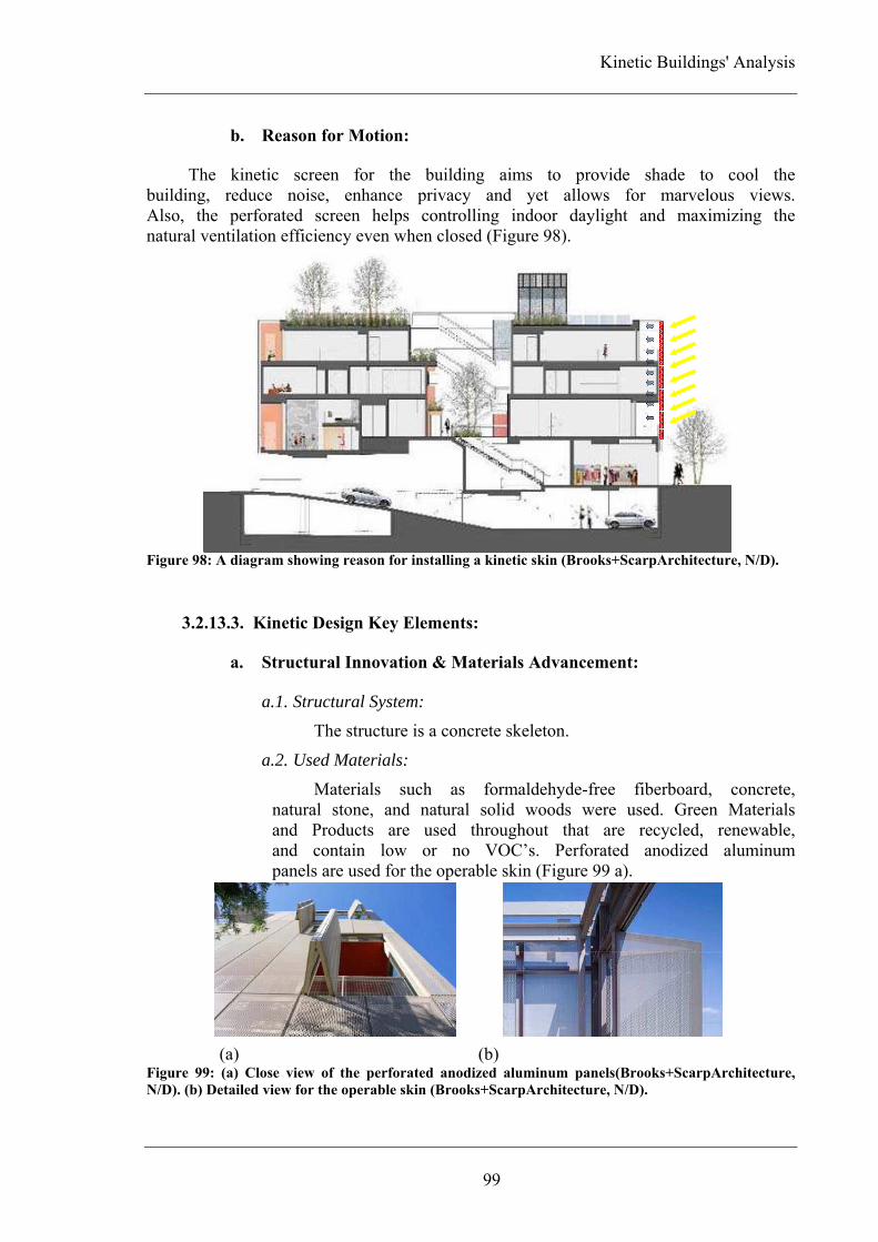
Kinetic Buildings' Analysis
99
b. Reason for Motion:
The kinetic screen for the building aims to provide shade to cool the building, reduce noise, enhance privacy and yet allows for marvelous views. Also, the perforated screen helps controlling indoor daylight and maximizing the natural ventilation efficiency even when closed (Figure 98).
Figure 98: A diagram showing reason for installing a kinetic skin (Brooks+ScarpArchitecture, N/D).
3.2.13.3. Kinetic Design Key Elements:
a. Structural Innovation & Materials Advancement:
a.1. Structural System:
The structure is a concrete skeleton.
a.2. Used Materials:
Materials such as formaldehyde-free fiberboard, concrete, natural stone, and natural solid woods were used. Green Materials and Products are used throughout that are recycled, renewable, and contain low or no VOC’s. Perforated anodized aluminum panels are used for the operable skin (Figure 99 a).
.
(a) (b)
Figure 99: (a) Close view of the perforated anodized aluminum panels(Brooks+ScarpArchitecture,
N/D). (b) Detailed view for the operable skin (Brooks+ScarpArchitecture, N/D).

Chapter Three
100
b. Embedded Computation / Control Mechanism:
The building's screen is operated manually; a hand push will turn the operable panels from completely closed to fully opened (Figure 99 b).
c. Adaptive Architecture:
This development is considered as a living environment although it has some commercial spaces on the ground level. Kineticism is installed in the building's façade allowing its residents to control the relation between the interior and the surrounding environment.
3.2.13.4. Indoor Environment Quality:
The location of the two-storey town home living space helped maximizing city sky-line views and both daylight and energy efficiency. All interiors designed to be eco-luxury with simple and modern lines while maintaining sustainability. The green roof for the Cherokee Lofts was designed as a garden with two terraces providing a pleasant place for its residents with breathtaking views. The perforated aluminum panels used on the south facing wall adds an unexpected depth while creating a sense of security for the residents by filtering the coming direct sunlight.
3.2.13.5. Building Visual Quality:
Dividing the façade into small moving panels added motion to the building by making it appear as if moving with pedestrians and cars (Figure 100).
Figure 100: A study showing the relation between solid and void through different stages starting from
all panels are close till reaching the stage when all panels are opened.

Kinetic Buildings' Analysis
101
3.1.14. The World Trade Center Transportation Hub
Figure 101: A perspective for the exterior of The World Trade Center Transportation Hub
(WorldTradeCenter, N/D).
3.2.14.1. General Information:
a. Completion Year: The project is still under construction (completion staled in 2014).
b. Architect: The hub is designed by Santiago Calatrava.
c. Building Cost: The project costs 3.8 billion USD.
d. Introduction:
The World Trade Center Transportation (WTC) Hub will not only add an architectural beauty to downtown Manhattan, but it will also enhance the level of services (Figure 101). The transportation hub is designed to accommodate 250000 pedestrians per day along with tourists and visitors of the World Trade Center and Memorial. Through the hub pedestrians will be able to access different directions as the hub is connected to 13 subway lines, Port Authority Trans-Hudson (PATH) trains, Hudson River ferry terminals as well as a possible direct rail link to John F. Kennedy (JFK) International Airport. The design of the hub was first revealed to the public in 2004. Later in 2005 and 2008, the design was revised to meet security, engineering and feasibility requirements.
e. Location:
The hub is located close to the northeast corner of the WTC site at Church and Fulton Streets (between Towers 2 and 3).

Chapter Three
102
f. Concept:
Santiago Calatrava got inspired by the gesture of a child releasing a dove into the sky (Figure 102 a,b). The hub entrance, the Oculus, consists of 300 steel pieces that features two 150 ft high wings located over a body built of two sets of glass and steel arches that are over 30 ft tall and weights between 10-25 tons for each. As the architect considered the light an important material involved in the design adding a welcome spirit to the interior, sunlight can go down way into the interior of the building to the rail platforms that are 60 ft below street level through the roof's ribbed glass and steel arches. In 2008, in order to reduce construction costs, the design of the steel wings was changed to a non-retractable.
(a) (b) Figure 102: (a) A sketch for a child releasing a dove into the sky which is the inspiration of the
designed building (CALATRAVA, N/D-b). (b) An exterior perspective for the WTC Transportation
Hub appears as a flying bird (CALATRAVA, N/D-b).
g. Building Components:
The new WTC Transportation Hub (Figure 103) will include: • A multi-storey central transit hall designed in the style of Grand Central Terminal, incorporating a lower concourse, an upper (balcony) concourse, a public waiting area, and first-class retail amenities. • Enhanced permanent PATH facilities and services incorporating three full-service extended 10-car platforms, as well as an additional platform to accommodate service needs and five tracks. • An integrated network of underground pedestrian connections from the lower and upper concourses, which will lead to adjoining New York City Transit subway stations and the proposed MTA Fulton Street Transit Center through the Dey Street Corridor. Pedestrians also will be able to access locations on and around the WTC site, including the five WTC office towers, the Memorial and Museum, Hudson River ferry terminals, the World Financial Center, PATH trains, 13 subway lines, and the proposed JFK rail link. • Retail facilities of approximately 200,000 ft2 within the transit hub and the pedestrian concourses accommodating a variety of restaurants and stores.

Kinetic Buildings' Analysis
103
Figure 103: A section for the WTC Transportation Hub (W. Dunlap, 2005).
3.2.14.2. Kineticism in the Building:
a. Kinetic Elements:
In the original design, the steel ribs with glass panels between them creating the ceiling of the hub were meant to open to 45 ft wide (Figure 104 a,b) before being reduced to 30 ft wide and changing the ceiling design into fixed later in 2008.
(a) (b) Figure 104: Section drawing showing the steel ribs that were supposed to move as well as the lightening
system (Yee, 2007, P. 63). (b) Interior prespective views for the main hall while the top is closed and
opened (LowerManhattanConstructionCommandCenter, N/D).
b. Reason for Motion:
The retractable glass and steel roof was planned to cover the freestanding grand pavilion which was going to open each year on the anniversary of the September 11th attacks in which a hanging American flag recovered from the ruins of the Twin Towers was going to be featured. Also, it was planned to be used to maximize natural light inside the hub.

Chapter Three
104
3.2.14.3. Kinetic Design Key Elements:
a. Structural Innovation & Materials Advancement:
a.1. Structural System:
The structure is a freestanding steel farm work.
a.2. Used Materials:
Steel, glass and concrete are used.
b. Embedded Computation / Control Mechanism:
The design of the transportation hub features advanced controlling, monitoring, security and signal systems. Those systems include closed-circuit television (CCTV) systems, physical intrusion protection, chemical, biological and radiological security. Also, platforms and mezzanines are climate controlled.
The retractable wings were supposed to be automated, moved by hydraulic motorized system that is connected to automatic control devices.
c. Adaptive Architecture:
A kinetic element was meant to be the building's wings allowing it to open on September 11th, the building itself was to be a magnificent memorial for the attack on the Twin Towers. The World Trade Center Transportation Hub creates a public environment that allows its users to access different directions and means of transportation as well as hosting commercial spaces.
3.2.14.4. Indoor Environment Quality:
The underground concourse, mezzanine and platform levels were designed to be free of vertical columns to maximize the sense of light, movement and openness. Opening the roof to allow sunlight to flood the interior of the transportation hub is an unusual strategy for a New York subway station. Sustainable design principles are applied to the project from energy efficient systems, indoor environmental quality, life-cycle costs and impacts, material resource and conservation, to enhance the interior and exterior building quality.
3.2.14.5. Building Visual Quality:
The design of the World Trade Center Transportation Hub calls for a soaring and a skeletal structure that is punctuated by white spires meant to represent a bird in flight. Although the station appears transparent, it seems to be protecting its users with the huge wings. The unusual style for the World Trade Center Transportation Hub is not only enjoyable by its users or the moving by pedestrians but also by the users of the towers above by looking down upon the hub.

Kinetic Buildings' Analysis
105
3.1.15. Dynamic Tower
Figure 105: A perspective for the Dynamic Tower (DynamicArchitecture, N/D).
3.2.15.1. General Information:
a. Completion Year: The tower was originally scheduled to open in 2010. Although the construction of the tower did not start until now, the architect insists that the reason is due to delays in land approvals not in financing and/or technical problems.
b. Architect: The tower is designed by Dynamic Architecture Group.
c. Building Cost: The tower will cost approximately 700 million USD.
d. Introduction:
David Fisher, the founder and chairman of Dynamic Architecture Group, thinks that building construction and materials used in the architectural field didn't develop since over 100 years ago when reinforced concrete was first used. Buildings are designed and built to last for 50 years while in old ages they lasted

Chapter Three
106
longer even for thousands of years. With means of construction and materials used in buildings today to achieve good quality, they result in expensive buildings that are unaffordable by many, slow to build and difficult to maintain. These buildings also are not capable to stand natural catastrophes such as earth quakes, hurricanes, typhoons or even strong winds, also adding errors done by humans such as malfunctioning of plumping, gas or electrical systems. David Fisher searching for a mean to design and construct buildings based on logic and engineering as well as being much safer, feasible and environment friendly resulted in the "Dynamic Tower". The Dynamic Tower (Figure 105) is an industrial production making it the easiest to design and build as all its floors look the same although they may host different uses. What adds the fancy shape to the building is motion making it not only a building but a living machine.
e. Location:
The tower is planned to be located in Dubai, UAE.
f. Concept:
The architect aims to create a safer building that can last and resist for a longer time by building the Dynamic Tower. The tower will be 420 m (1380 ft) tall. It is designed to be self powered by sun and wind as well as being industrialized making it sustainable and smart. There will be 79 wind turbine systems installed horizontally in the gaps between each of the rotating floors (Figure 106). Also, photovoltaic solar cells will be installed on the roof of each floor to produce solar energy (Figure 106 b). With energy produced from 20% of each of the 80 roofs exposed to sun and light next to the energy produced by wind turbines, the tower will be able not only to fulfill its needs of energy but also to supply 10 similar sized buildings with energy. As almost 90% of the tower will be constructed in factory, the number of on-site workers will be reduces from almost 2000 to 90 (Fisher, 2010).
(a) (b) Figure 106: (a) Drawing representing the installation of wind turbines and the way they are involved in
the design concept (DynamicArchitecture, N/D). (b) Drawing representing the use of solar panels on
top of each rotating floor (DynamicArchitecture, N/D)

Kinetic Buildings' Analysis
107
g. Building Components:
The Dynamic Tower is made up of 80 pre-fabricated floors. The retail space is located in the first lower 20 floors, while the hotel takes place in the next 15 floors. The residential part of the tower is located in the top 45 floors, 35 floors are dedicated for apartments while the top 10 floors are for luxurious villa-style apartments (Figure 107 a,b). The residential space will range in size from 124 m2 (1330 ft2) for apartments to 1200 m2 (12900 ft2) for villas and all are with a parking space inside.
(a) (b) Figure 107: Dynamic Tower floor plans (DynamicArchitecture, N/D). (a) Plan drawing for the villas
which are located on the top 10 floors. (b) Plan drawing for the hotel unites which is located on the first
lower 20 floors.
3.2.15.2. Kineticism in the Building:
a. Kinetic Elements:
The Dynamic Tower consists of 80 floors that rotate creating the first kinetic element in the tower, while the second element is the 79 wind turbines located between each of those floors.
b. Reason for Motion:
While the tower's wind turbines produce energy, the floors may rotate to fulfill their users' desires of changing views or to follow sun and light to produce energy.
3.2.15.3. Kinetic Design Key Elements:
a. Structural Innovation & Materials Advancement:
a.3. Structural System:
The Dynamic Tower will be pre-fabricated and industrialized. The only part of the tower that will be constructed

Chapter Three
108
on-site is the tower central core. Each of the tower floors will consist of 12 modules that will be fully built in factory before arriving at the site. Those modules will be assembled around the core base and then will be lifted up by cranes and cables (Figure 108).
a.4. Used Materials:
The tower's units are made of steel, aluminum, carbon fiber and other high quality modern materials. Natural and recyclable materials including stone, marble, glass and wood are intended for the interior finishing.
Figure 108: Drawing presenting the technical system will be used to construct the tower
(DynamicArchitecture, N/D).
b. Embedded Computation / Control Mechanism:
It is planned to install the most advanced monitoring systems and technologies to the Dynamic Tower. Tower residents and users will be able to control rotation and other installed systems though out a voice-active mechanism.
c. Adaptive Architecture:
Although the tower hosts retail spaces, the Dynamic Tower is considered to create living environment as the residential part (hotel, apartments and villas) create 75% of the tower uses. Kineticism creates the tower itself because each of its 80 floors separately revolves around the central core.
3.2.15.4. Indoor Environment Quality:
The tower residents will be able to rotate the floors according to their desire whether to choose their favorite view, follow the sun or even set it to slowly

Kinetic Buildings' Analysis
109
rotate to enjoy all possible views. Using smart, recyclable and natural materials as well as advanced technologies offers all tower users sustainable, clean and safe environments to live and/or work within (Figure 109). With such technologies it is possible to control all systems installed just by voice (Cherry, 2010).
Figure 109: Drawings representing natural ventilation as well as sunlight filtering
(DynamicArchitecture, N/D).
3.2.15.5. Building Visual Quality:
The tower will have a futuristic look. As the floor plans are triangular and they separately move according to desire, the tower will continuously change its form and shape in varies variety of configurations. According to the architect, the Dynamic Tower will never look the same twice in its lifetime (Figure 110). Figure 110: Different views for the Dynamic Tower while in motion (Cherry, 2010, P. 36).

Chapter Three
110
The table below briefly highlights the analytical criteria for each of the fifteen evaluated buildings. Buildings are categorized according to type of indoor environment.
Gen
era
l In
form
ati
on
Na
me
GucklHupf Floirac House
Naked House
Gemini Haus
Dragspelhuset
Sliding House
Cherokee Studios
Dynamic Tower
Pic
ture
Co
mp
leti
on
Yea
r
1993 1998 2000 2001 2004 2009 2010 Construction didn't start
yet
Arc
hit
ect
Hans Peter Wörndl
Rem Koolhaas (OMA)
Shigeru Ban Roland Mösl
24>H architecture
dRMM Architcts
Brooks + Scarpa
Dynamic Architecture
Group
Cost
N/A N/A 225,000
USD N/A 80,000 € N/A N/A
700 million USD
Lo
cati
on
Mondsee, Austria
Bordeaux, France
Saitama, Japan
Weiz, Austria
Glaskogen, Sweden
Suffolk, UK California,
USA Dubai, UAE
Kin
etic
ism
in
th
e B
uil
din
g
Kin
etic
Ele
men
ts Building
Elevator platform
Moveable boxes
Building and solar
panels
Expandable room
Sliding structure
Aluminum panels
Building
Whole Structure
Indoor element
Indoor element
Indoor element
Structure part
Structure part
Elevation elements
Whole Structure
Rea
son
fo
r M
oti
on
Fuctional – creating flexibile spaces
Functional - accessibility
Functional –creating flexibile spaces
Environmental – light control, reduce energy
consumption and
natural ventilation
Functional – creating flexible spaces
Environmental – control light, adjust
cool and heat loads
Environmental – light control, reduce energy
consumption and
natural ventilation
Luxurious and
environmental
Kin
etic
Des
ign
Key
Ele
men
ts
Str
uct
ura
l In
no
va
tio
n &
Mate
rials
Ad
van
cem
ent
Str
uct
ura
l
Syst
em
Frame structure
Reinforced concrete structure
Frame structure
Frame structure
Frame structure
Frame structure
Reinforced concrete structure
Prefabricated structure
Use
d M
ate
rials
Wood, glass and
aluminum
Aluminum sheets and
steel
Timber and paper
honeycom panels
Steel and glass
Red cedar wood, pine lattice and
steel
Steel, timber and
glass Aluminum
Steel, aluminum and carbon
fiber
Con
tro
l
Mec
ha
nis
m
Automatic device –
Automated system
Remote control
device – Automated
system
Manual control
Automatic device –
Automated system
Manual control – system of robs and pulleys
Remote control
device – Automated
system
Manual control
Remote control
deivce – Voice-active system
Ad
ap
tab
le
Arc
hit
ectu
re
Living environment

Kinetic Buildings' Analysis
111
Table 2: Analyzed architectural projects.
Gen
era
l In
form
ati
on
Na
me Kiefer Technic
Showroom Institut du
Monde Arabe
Milwaukee Art Museum
"Quadracci Pavilion"
QiZhong Forest Sports City Tennis
Center
The Olympic Tennis Center "Magic Box"
The Leaf Chapel
The World Trade Center Transportatio
n Hub
Pic
ture
Co
mp
leti
on
Yea
r
2007 1987 2001 2005 2009 2004 To be
completed in 2014
Arc
hit
ect Ernst
Giselbrecht + Partner
Architektur
Jean Nouvel Santiago Calatrava
Mitsuru Senda Dominique
Perrault Architecte
Klein Dytham Architecture
Santiago Calatrava
Cost
N/A 47,500,000
USD 122 million
USD 200 million
USD 150 million € N/A
3.8 billion USD
Lo
cati
on
Bad Gleichenberg,
Austria Paris, France
Wisconsin, USA
Shanghai, China
Madrid, Spain Kobuchizawa,
Japan New York,
USA
Kin
etic
ism
in
th
e B
uil
din
g
Kin
etic
Ele
men
ts Aluminum
panels Mashrabia diaphragms
Steel wings Roof petals Roof lids Leaf wall Steel wings
Elevation elements
Façade elements
Roof element Roof elements Roof elements Walls Roof elements
Rea
son
fo
r
Mo
tio
n
Environmental – light control
Environmental – light control
Environmental – light control
Environmental – light
control and adating to weather
Environmental – light
control and adating to weather
Desing concept
Concept and environmental – light control
Kin
etic
Des
ign
Key
Ele
men
ts
Str
uct
ura
l In
novati
on
& M
ate
rials
Ad
van
cem
ent Str
uct
ura
l
Syst
em Reinforced
concrete structure
Frame structure
Frame structure
tension ring structure
Reinforced concrete structure
Frame structure
Frame structure
Use
d M
ate
rials
Aluminum panels, glass and stainless
steel
Glazed aluminum, steel, glass and light sensitive
diaphragms
Steel and wind sensors
aluminum aluminum Steel and
glass Steel and
glass
Con
tro
l M
ech
an
ism
Automatic device –
Automated system
Computer output device – Automated
system
Automatic device –
Automated system
Automatic device –
Automated system
Automatic device –
Automated system
Automated control
Automatic device –
Automated system
Ad
ap
tab
le
Arc
hit
ectu
re
Working environment
Entertainment environment Public environment

Chapter Three
112
3.2. Analysis:
3.2.1. Location:
The selected projects are located in three continents; Europe, North-America and Asia (Figure 111). Eight projects are located in Europe where three of them are located in Austria, two are located in France and one is located in each of UK, Spain and Sweden. Three of the selected projects are located in North-America where all are located in the USA. The last four projects are located in Asia where two are located in Japan, one is located in China and one is planned to be located in the Dubai, UAE.
Figure 111: The world map where the studied projects are located in Europe, North-America and
Asia.
3.2.2. Structural Systems and Used Materials:
Different structural systems are used for kinetic buildings varying from frame to concrete structures as well as tension ring and prefabricated structures. The most common type used in the buildings analyzed is the frame structure with 46% represented in 7 projects followed by concrete structure with 40% represented in 6 projects (Figure 112).
Figure 112: Structure systems used for analyzed buildings.
0
10
20
30
40
50
Frame Structure 46% Concrete Structure 40% Tension Ring Structure 7%
Prefabricated Structure 7%

Kinetic Buildings' Analysis
113
Many materials are used in kinetics installed on/in buildings. Sometimes only one material is used, while on other times a combination of different materials are being used. Most materials commonly used are characterized by light weight as well as flexibility like aluminum, paper, stainless steel and fibers. Steel and aluminum are the most materials commonly used combined with other materials like glass or some other smart materials such as sensors (Figure 113).
Figure 113: Share of materials used among the studied projects.
3.2.3. Indoor Environment Types:
Based on the kinetic design key elements, studied projects are categorized into four environments which are living, working environments, entertainment and public environments (Figure 114). 53% of the analyzed buildings are categorized under living environments varying from single-level private houses to multi-levels private houses and multi-storey residential buildings. Entertainment environments, varying from cultural centers to museums as well as stadiums, have a share of 27%, while public environments that varied from transportation hubs to more spiritual facilities like wedding chapels have a share of 13%. Work environments came at the end with a share of only 7% based on one analyzed building which is Kiefer Technic Showroom.
Figure 114: Different architectural environments in which kinetics were used.
0
10
20
30
40
50
60
Living Environments 53%
Work Environments 7%
Entertainment Environments 27%
Public Environments 13%
0
20
40
60
80
100
Steel 60% Aluminum 60%
Glass 86% Wood 46% Paper 13% Smart Materials
33%
Stainless Steel 13%
Carbon Fiber 7%

Chapter Three
114
3.2.4. Kinetic Elements and Reasons for Motion:
Kinetics are being used in buildings by different ways. In buildings under study kineticism is used in six different ways; as kinetic elevation elements, interior elements, roof elements, kinetic walls, kinetic part of the structure itself or as the building as a whole (Figure 115). Sometimes a building can adopt different types of kineticism. The most common kineticism used in the buildings under study are kinetic elevation and roof elements (Figure 116).
(a) (b) (c)
(d) (e) (f) Figure 115: Types of kineticism used in buildings under study, such as: (a) Institut du Monde Arabe –
1987 (eliinbar, 2011). (b) The Naked House – 2000 (Stang, 2005, P. 89). (c) The Olympic Tennis Center
– 2009 (DominiquePerraultArchitecture, N/D). (d) The Leaf Chapel – 2004 (Picasa, 2009). (e) The
Sliding House – 2009 (Meunier, 2012). (f) The Dynamic Tower (DynamicArchitecture, N/D).
Figure 116: Ways kinetics were installed in buildings.
0
5
10
15
20
25
30
Elevation Elements 26%
Interior Elements 13%
Roof Elements 26%
Walls 13% Structure Part 13%
Whole Structure 13%
Institut du Monde Arabe Kinetic Elevation Element
The Naked House Kinetic Interior Elements
The Olympic Tennis Center Kinetic Roof Elements
The Leaf Chapel Kinetic Walls
The Sliding House Kinetic Structure Part
The Dynamic Tower Whole Kinetic Structure

Kinetic Buildings' Analysis
115
There are some reasons behind using kinetics in the sample studied. They may vary from environmental reasons, design concepts, creating flexible spaces and luxury (Figure 117). In some cases there are more than one reason for using kinetics. The most common reason for using kinetics is controlling and filtering the incoming light (Figure 118).
(a) (b) (c) (d)
(e) (f) (g) (h) Figure 117: Reasons for using kinetics, such as: (a) Institut du Monde Arabe – 1987 (Dumas, 2009). (b)
GucklHupf – 1993 (Olson, 2009). (c) Maison à Bordeaux – 1998 (OMA, N/D). (d) The Naked House –
2000 (van Poucke, 2011). (e) Magnolia Stadium – 2005 (TheChicagoAthenaeum, 2007). (f) The Leaf
Chapel – 2004 (IaaC, 2010). (g) Cherokee Studios Lofts – 2010 (Brooks+ScarpArchitecture, N/D). (h)
Dynamic Tower (DynamicArchitecture, N/D).
Figure 118: Reasons in which kinetic systems are applied.
0
10
20
30
40
50
60
70
Light Control 67%
Space Flexibility 27%
People with Special Needs Accessibility
7%
Reduce Energy Consumption
27%
Respond to Weather
Changes 27%
Design Concept 20%
Natural Ventilation
14%
Luxury 7%
Institut du Monde Arabe
Light Control
GucklHupf Space Flexibility
Maison à Bordeaux People with Special Needs Accessibility
The Naked House Reduce Energy Consumption
Magnolia Stadium Respond to Weather
Changes
The Leaf Chapel Design Concept
Cherokee Studios Lofts
Natural Ventilation
The Dynamic Tower Luxury

Chapter Three
116
3.2.5. Relation between Structural System and Used Materials:
There is a relationship between the structure system and the materials used across the buildings. When frame structures are used, materials such as steel, wood and paper along with other smart materials were easily applied as the structure itself is light weighted. When much heavier structures are used like reinforced concrete structures and tension ring structure, aluminum is the most used to add flexibility and smoothness to the system (Figure 119).
Figure 119: Relation between structure systems and materials share.
3.2.6. Relation between Structural System and Used Kinetic Elements:
Using frames as a structure system made it easier to install different kinetic systems in buildings that varied from elevation elements, interior elements, roof elements, kinetic structure part and kinetic walls. Kinetic walls as well as kinetic structure parts are the most used when structures are frames. Reinforced concrete structures allow for limited flexibility when using kinetic systems. Kinetic elevation elements as well as kinetic interior elements are the most common when structures are concrete (Figure 120).
Figure 120: Structure systems effect on the way kineticism is installed.
0.00%
2.00%
4.00%
6.00%
8.00%
10.00%
12.00%
14.00%
Frame Structure Concrete Structure Tension Ring Structure
Prefabricated
Steel
Aluminum
Glass
Wood
Paper
Smart Materials
Stainless Steel
Carbon Fiber
0.00%
2.00%
4.00%
6.00%
8.00%
10.00%
12.00%
14.00%
16.00%
18.00%
Frame Structure Concrete Structure
Tension Ring Structure
Prefabricated
Elevation Elements
Interior Elements
Roof Elements
Walls
Structure Part
Whole Structure

Kinetic Buildings' Analysis
117
3.2.7. Relation between Building Environments and Used Kinetic Elements:
When kinetics were applied to living environments, they varied from kinetic elevation elements, interior elements, kinetic walls to kinetic structure part as well as kinetic whole buildings. Using kinetic roofs were most common with entertainment environments as well as public environments (Figure 121).
Figure 121: Relation between the different architectural environments and ways kinetics are installed.
3.2.8. Relation between Building Environments and Reasons for Motion:
Kinetics were used in living environments to achieve different possibilities that varied from creating flexible spaces, handicap accessibility, controlling light, responding to weather changes, reducing energy consumption, improving natural ventilation as well as design concept and luxury. Light control was the common reason to apply kinetics in work environments as well entertainment and public environments (Figure 122).
Figure 122: Relation between different architectural environments and the reason kinetics are used.
0.00%
2.00%
4.00%
6.00%
8.00%
10.00%
12.00%
14.00%
16.00%
Living Environment
Work Environment
Entertainment Environment
Public Environment
Light Control
Space Felxibility
Handicapped Accessibility
Reduce Energy Consumption
Respond to Weather Chnages
Design Concept
Natural Ventilation
Laxury
0.00%
5.00%
10.00%
15.00%
20.00%
25.00%
Living Environment
Work Environment
Entertainment Environment
Public Environment
Elevation Elements
Interior Elements
Roof Elements
Walls
Structure Part
Whole Structure

Chapter Three
118
3.2.9. Ways of Controlling Kineticism and the Relation with Building
Environments:
Controlling kinetic systems varied from using simple systems to using more complicated ones connected to sensors, detectors and computers. There are four ways to control kinetic systems installed to analyzed projects which are: manual control, automatic control, automatic control with pre-programmed settings and automatic control with pre-programmed settings while allowing users to modify settings according to their needs and desires (Figure 123). The most used way of controlling kineticism is automatic control systems with pre-programmed settings (Figure 124). Automatically controlled kinetic systems with pre-programmed settings are widely used in entertainment environments, while manually controlled kinetic systems are used in living environments (Figure 125).
(a) (b) (c) (d) Figure 123: Different ways of controlling kinetic systems, such as: (a) Cherokee Studios Lofts – 2010
(SlowHomeStudio, 2010). (b) Gemini Haus – 2001 (Salzburg.ORF.at, 2012). (c) Milwaukee Art
Museum Quadracci Pavilion – 2001 (CALATRAVA, N/D-a). (d) Kiefer Technic Showroom – 2007
(WorldBuildingsDirectoryOnlineDatabase, N/D).
Figure 124: Ways of controlling kinetic systems.
Figure 125: Relation between different architectural environments and ways of controlling kineticism.
05
101520253035
Manual Control Kinetic Systems 20%
Automatic Control Kinetic Systems 20%
Automatic Control Kinetic Systems with Pre-programmed
Settings 33%
Automatic Control Kinetic Systems with Pre-programmed Settings with Users Ability to Change Settings According to
Their Needs 27%
0
5
10
15
20
25
30
Living Environments
Working Environments
Entertainment Environments
Public Environments
Manual Control Kinetic Systems
Automatic Control Kinetic Systems
Automatic Control Kinetic Systems with Pre-programmed Settings
Automatic Control Kinetic Systems with Pre-programmed Settings with Users Ability to Change Settings According to Their Needs
Cherokee Studios Lofts Manual Control
Gemini Haus Automatic Control
Milwaukee Art Museum Automatic Control with
Pre-programmed Settings
Kiefer Technic Showroom Automatic Control with
Pre-programmed Settings while Allowing Users to
Change Settings

Kinetic Buildings' Analysis
119
3.2.10. Kinetic Systems Effect on Buildings' Visual Quality:
Kinetic systems that are applied to the exterior of buildings helped improving the buildings' visual quality. In the analyzed projects, kinetic systems affected the visual quality by either allowing the building to hide and melt with its natural surrounding environment such as the Dragspelhuset in Sweden or reflecting the changeable daily patterns such as the Dynamic Tower to be built in Dubai, UAE (Figure 126 a,b). Other kinetic systems presented cultural dimension such as the QiZhong Forest Sports City Tennis Center in Shanghai with is kinetic roof appearing as a magnolia blossom which is the national flower of Shanghai (Figure 126 c). Also, other kinetic systems presented social dimensions such as the World Trade Center Transportation Hub that acts as a 9/11 memorial (Figure 126 d).
(a) (b) (c) (d) Figure 126: Effect of using kinetic systems on buildings' visual quality. (a) Dragspelhuset – 2004
(HomesAndInterorDesign, N/D). (b) The Dynamic Tower (Cherry, 2010, P. 36). (c) QiZhong Forest
Sports City Tennis Center – 2005 (IaaC, 2010). (d) The World Trade Center Transportation Hub –
2014 (CALATRAVA, N/D-b).
3.3. Summary:
Based on the analytical study for various architectural projects, the following is proposed: • Although the Middle-East is well known for its sunny and hot
weather and can greatly benefit for kinetic architecture, most of the buildings understudy are located in Europe, while only one building is planned to be located in the Middle-East. • As kinetic systems are installed in/on different structural systems, it is important to mention that frame structures present more flexible solutions for interiors. Also, frame structures allow a wide range of kinetic systems to be applied. • While a wide range of kinetic materials varying from fabricated/industrialized to natural materials, almost all used kinetic materials are light weight. • Kineticism is applied to different environments, but it is most commonly used in living environments whether they are part of multi-family housing, private houses or even residential sky-scrapers.
Dragspelhuset Hide and Melt with the
Natural Surrounding Environment
The Dynamic Tower Reflect Changeable Daily
Patterns
QiZhong Forest Sports City Tennis Center
Present Cultural Dimension
The World Trade Center Transportation Hub
Present Social Dimension

Chapter Three
120
• There are different ways for kinetic systems to be installed in/on a building. These systems can allow the whole building to be in motion or just a part of it, whether indoor or outdoor. The most common kinetic systems used in buildings examined are kinetic roof elements. • Kineticism is applied to buildings in order to adapt to weather changing patterns, save energy as well as allow for environment-friendly energy sources, allow for natural ventilation and control light. There are many other reasons to adopt kinetic systems in buildings, but as previously mentioned environmental reasons are the most common. • There are different factors that affect how kineticism is applied to analyzed architectural projects which include used structure systems, used materials, reason behind applying these types of systems as well as other factors. Each of these factors is affected by the rest. When frame structures are used that reflected on used materials which varied from steel, to wood and paper. Also, using other structure systems affected the materials used. • The used structure system affected the installed type of kineticism. The most common structure system used in the analyzed projects is frame structure. This type of structure system allows for many types of kinetic systems to be installed, such as elevation kinetic elements, kinetic walls and other systems. • Structure systems are not the only factor that affected the used type of kineticism, the environment within the building equally affects the type of kineticism. Using kinetic facades, or walls as well as interior elements is suitable to living environments. • The reason behind applying kinetic systems is affected by the nature of the environment that the building creates. When a kinetic system is installed to a living environment that is to allow for more privacy, create more flexible living spaces, to add luxury as well as other environmental reasons.

CONCLUSIONS AND RECOMMENDATIONS


Conclusions & Recommendations
123
Conclusions According to different definitions for the term "Kinetic Architecture" it can
be described as a building or building parts that act in response to surrounding changes that occur indoor and/or outdoor whether they are caused by natural and/or human factors. Based on the definition, kinetic design is based on three main key elements: 1) structural innovation and materials advancement, 2) embedded computation, and 3) adaptable architecture. The first key element in kinetic design – structural innovation and materials advancement – represents the building and building parts, while the second key element – embedded computation – allows building to detect change and act according to it, thus creating environments that are able to adapt and interact representing the third key element which is adaptable architecture. Based on different parts of this research, a building analyses was carried out in order to understand the different means and ways in which kineticism could be applied to built environments. Selection of buildings was based on different factors included completion year, building's use and type of kineticism involved. The analysis criteria incorporated means and reasons for including kineticism in the design as well as the effect of using such kinetic solution on both the indoor environment quality and the building visual quality. Based on this study the following is concluded:
• When kinetic systems are installed in buildings, they can be controlled by different means. Controlling kinetic systems may range from simple means by manual control to complicated automatic control. Automatic control complexity can vary from just allowing users to take a certain action by turning the system on and off to more complicated pre-programmed automatic systems. These systems can be fully automated while being connected to a set of sensors and detectors to realize any changes that occur allowing these kinetic systems to respond according to pre-programmed settings in which buildings' users can't interfere or change. Also, some pre-programmed automated kinetic systems may be set to allow users to interact with systems adding changes and modifications even when connected to sensors. Moreover, kineticism can be installed in buildings without using any kind of embedded computation and/or automated systems allowing buildings users to manually fold, slide or even push different parts creating the environments they desire. • There are many ways where kineticism can be used in the architectural field representing a wide range of solutions. Kinetic systems can be used as indoor elements ranging from small elements such as furniture to larger elements such as walls/partitions, floors and ceilings. Kinetic systems can be used to create the building's envelope represented by walls and roof elements or even kinetic systems that can be attached to the building's outer-skin. Kineticism can appear as a part of the building's structure or as the structure as a whole allowing it to transform.

Conclusions & Recommendations
124
• No matter how kinetic systems are being controlled and even how they are installed to buildings, they allow the environments they create to be flexible and adaptable to changes. Kineticism, when installed to buildings, will allow users to reconfigure environments they occupy. Kinetic systems will allow users to control the relation with the surroundings by allowing for more privacy or transparency. These systems will allow users to change how they are connected to other parts of the building or even how they are open to the outdoors. Kinetic buildings' users may be able to reconfigure space by changing its size to bigger or smaller depending on their needs and desires. • Installing kinetic systems in buildings will increase costs, on the other hand, if those systems are employed to maximize the use of sunlight, natural ventilation and energy efficiency, which will result in reducing buildings' running costs on the long run. The cost of using such kinetic systems is affected by the materials used as low-cost materials can be used as well as those environment-friendly and high-tech materials. The way to control kinetic systems can affect the cost as well. Using manually controlled systems can decrease cost while using pre-programmed automated systems involving sensors and detectors can push cost even higher. • There are many reasons to involve kineticism in the architectural design. Kineticism can be used to achieve environmental goals. Such systems can be used to increase the efficiency of natural light and ventilation as well as to save energy. Using kineticism can achieve space efficiency by not only increasing the indoor environment quality but also by allowing it to transform in size and shape. Kinetic systems can be used for conceptual reasons in order to attract audience and represent cultural as well as social dimensions.
Egypt is blessed with its special location at a crossroad between Africa, Asia and Europe. The Nile River flows across Egypt from south to north creating the Nile Valley and Delta which is the main region. In addition there are three other regions which are the Western Desert, the Eastern Desert and Sinai Peninsula. Egypt is bordered by the Mediterranean Sea on the North and the Red Sea on the East. The Egyptian environment is not only blessed with special location but also with many natural resources, moderate weather and land availability. As kinetic systems represents untraditional solutions for different problems that may face architects, applying such systems to the Egyptian architectural environment will increase its efficiency. Kinetic systems can be used in the Egyptian environment in order to maximize the use of renewable energy sources. Also, kinetic systems will both improve and increase natural light and ventilation efficiency as well as space efficiency when installed to the Egyptian environment.

Conclusions & Recommendations
125
• Energy Saving: Despite the fact that Egypt is being characterized by its sunny weather most of the day all year round, solar energy is still in its infancy. Kinetic systems can be applied to the Egyptian architectural environment to maximize the use of solar energy. These systems will include solar panels/photovoltaic cells, sensors and/or detectors. They can be designed not only to act as source for renewable energy but also as means of thermal insulation and energy radiation controller. Such kinetic systems can be suitable for different types of environments varying from living environments to work, entertainment and public environments.
(a) (b) (c) Figure 127: (a) The dynamic façade of the Kiefer Technic Showroom
(WorldBuildingsDirectoryOnlineDatabase, N/D). (b) The movable solar panels attached to the
exterior of Gemini Haus (Lenardic, N/D). (c) The FLARE-façade system (WHITEvoid, N/D).
These systems can be designed to create kinetic skin for the whole building. The kinetic system used for the Kiefer Technic Showroom (Figure 127 a) is an example of such systems where it can be modified to involve solar panels as well as perforated panels depending on the design and need. Also, they can be designed whether to be attached to the static exterior walls of the building while only solar panels are able to fold, rotate or even slide, or allow the structure to revolve as a whole in order to follow the sun. The kinetic system used at the Gemini Haus (Figure 127 b) is an example where movable solar panels are attached to the exterior walls of the house. Systems such as the FLARE-façade system (Figure 127 c) can be installed to existing building facades while the FLARE units are modified to allow photovoltaic cells to be added on top of them. Such addition will turn the building from its static form to a dynamic one by adding motion to it, at the same time photovoltaic cells will increase the energy efficiency for the building by utilizing the power of solar energy.
• Natural Light and Ventilation Efficiency: Kinetic systems can be used in order to control the natural light and ventilation whether for major projects like museums, cultural centers and sports facilities or for residential projects varying from single family

Conclusions & Recommendations
126
housing to high-rise residential buildings. Such systems can be designed to be manually controlled or automated. Also, a wide range of materials can be used in such systems varying from low-cost materials to high-tech materials. These systems can also allow users to control their privacy level and their relation to the outdoor environment especially in residential projects.
(a) (b) (c) Figure 128: (a) The aluminum panels used for the Wind Veil (beautrincia, 2008). (b) The perforated
aluminum panels used for the Cherokee Studios Lofts (Brooks+ScarpArchitecture, N/D). (c) The
Mashrabiya Diaphragms used for the Institut du Monde Arabe (eliinbar, 2011).
These kinetic systems can be designed to be able to move freely by wind such as the Wind Veil (Figure 128 a). This system needs to be controlled neither manually nor automatically. As wind blows all over Egypt, there are several regions that are promising to be high source for wind energy such as the Gulfs of Suez and Aqaba as well as Western Desert. Yet that system will not be used as an energy source. This system turns the building façade from a static condition to an ever changing dynamic condition depending on wind direction and currents. The perforated aluminum screen used for the Cherokee Studios Lofts (Figure 128 b) represents another kinetic system used to improve the use of natural light and ventilation that can be applied to the Egyptian environment using local materials. The previously mentioned systems can be applied to residential buildings allowing users not only to control the natural light and ventilation but also to control their relation with the outdoor environment by improving privacy level and decrease noise level. The Mashrabiya Diaphragms (Figure 128 c) used for the Institut du Monde Arabe is an example of complicated kinetic systems that are automatically controlled through pre-programmed settings. Such system represents solutions to be applied to major project not only in order to control daylight but also to attract audience. It is recommended when using automated kinetic systems to be accompanied with renewable energy feeding source in order to reduce energy consumption. • Space Efficiency: Kinetic systems can be applied in the Egyptian environment in order to improve space efficiency whether by allowing it to transform in size and/or shape or by allowing its users to reconfigure it depending on their

Conclusions & Recommendations
127
needs and desires. Such systems can be efficiently used for temporary buildings, multi- purpose buildings as well as residential and work environments. Although it is better to involve kinetic systems into the design since its early stages, some kinetic systems can be solution for existing buildings. These systems can be used not only to improve space efficiency but also to control the relation with different parts of the building as well as the outdoor environment. The cost of such systems can vary depending on the level of technology applied, materials used and controlling systems used.
(a) (b) (c) Figure 129: (a) The Bloomframe (HurksGeveltechniek, N/D). (b) The Dragspelhuset
(24H<architecture, N/D). (c) The GucklHupf (Olson, 2009).
In low-income housing built by the Egyptian government, residents seek illegal means in order to expand their living spaces by building illegal extensions to the main structure. To face such means, there are systems that can provide flexible kinetic solutions to expand spaces. The Bloomframe (Figure 129 a) is a kinetic system that can be applied to existing buildings in order to allow users to expand the size of the space. This kinetic system can be of great use for living environments. Such system can be installed to residential buildings and hotels that are characterized by their small areas. This system can be applied to the Egyptian architectural environment allowing designers to improve space efficiency by using all area possible for main living facilities while balconies will be optional, occupants can choose whether to open or close them depending on their needs and desires. Another example of kinetic system that can be applied to the Egyptian environment in order to improve space efficiency is that used for the Dragspelhuset (Figure 129 b). This system consists of a retractable cantilever that can be pushed out/in according to needs. The GucklHupf (Figure 129 c) is an example of kinetic systems that can be applied to the Egyptian environment especially for buildings that are not in use all year round such as sea cabin that are used only during summer season. • Presenting untraditional modern solutions by applying kinetic
systems to the Egyptian architectural environment can be accompanied with Egyptian heritage and culture through the

Conclusions & Recommendations
128
conceptual design of the kinetic system itself and/or through the materials used.
Recommendations: Although architecture has an influence on the environment it creates, it is
affected by different factors that include technology, users and environment whether natural or built. In order to improve the quality of the architectural environment, kinetic architecture can be the solution to create environmental-friendly, safe, organized, enjoyable and adaptable environments. To achieve extremely useful results, architects should work in teams to improve research with collaboration with specialists from different fields. These fields may range from engineering such as information technology, communications, mechanical and structural engineering to social as well as environmental science.
Involving researchers from different fields of engineering and science will result in improving and developing locally designed kinetic systems. Locally designed kinetic systems will act more efficiently in the Egyptian environment. These systems will be designed using local materials and systems. They will also be designed to meet different weather conditions such as high temperatures, humidity, sandstorms (Khamasin winds) and rain. Also, designing local kinetic systems will consider the different Egyptian cultural backgrounds for each region they will be applied to.
Although Egypt is considered as a developing country, it has a lot of areas including villages and rural developments that lack basic services such as medical/health care and educational services. In order to fulfill these services, it is of great importance to employ kinetic design in creating multi-functional units that can transform to meet each function separately and efficiently. These functions may vary from medical convoy units to general and specialized clinics as well as one-day schools, literacy classes, units for technical schools and applied faculties. Also, it is of great importance to involve kinetic systems in designing portable multi-functional units that can be used in emergencies and natural disasters such as floods and earthquakes.
Planners should work hard in order to look for means and ways to invent and implement ideas at the rate requested for keeping up with the rest of the world. It is of great importance to carry out researches in order to understand how kinetic architecture will affect urban planning. Kinetic design will provide planners with creative means for problem solving using technological advancements that facilitate decision making and collaboration between different interest groups during the process. Whether it is the continuing influence of Internet or new ways of using clean energy, a wide range of technological innovations will help shape cities of the future. If urban planners will consider events, activities and changes rather than buildings and structures, they can provide greater comfort and safety for all residents.

References
i
REFERENCES
- 24H<architecture. N/D. Evolution-Dragspelhuset at Övre Gla, Sweden [Online]. Available: http://www.24h.eu/.
- A. Pearson 2005. Leaf Chapel - Kobuchizawa, Japan. Architectural Record. New York: McGraw-Hill Construction.
- a.allegretti. 2012. Turned wood mashrabiya window [Online]. Available: http://aestheticsjr.blogspot.com/2012/01/turned-wood-mashrabiya-window.html.
- Addis 1997. Lightweight Structures. In: Walker (ed.) Happold: The Confidence to Build. Bath: Happold Trust Publications Ltd.
- AlternativeBerlin. 2010. Blinkenlights.. [Online]. Available: http://alternativeberlin.com/blog/?cat=1&paged=3.
- AMX. N/D. AMX Whole Home Automation System [Online]. Available: http://www.amx.com/markets/residential/wholehome.asp [Accessed May 31 2012].
- Ballard Bell 2006. Materials for Architectural Design, London, Laurence King Publishing Ltd.
- beautrincia 2008. "windveil" parking deck- Charlotte- 03
- Beck. N/D. Rem Koolhaas/OMA: House in Floirac, Bordeaux, France [Online]. UME Magazine. Available: http://www.umemagazine.com/scrollSpreads.aspx.
- Block. 2011. Contained: All things container [Online]. Available: http://contained.tumblr.com/post/3786604612/lot-eks-mdu-mobile-dwelling-unit-features-side.
- Bradbury 2005. New Country House, London, Laurence King Publishing Ltd.
- Brooks+ScarpArchitecture. N/D. Cherokee Lofts [Online]. California: Brooks+Scarpa. Available: http://www.pugh-scarpa.com/projects/cherokee.lofts.
- Brownell (ed.) 2008. Transmaterial 2: A Catalog of Materials That Redefine Our Physical Environment, New York: Princeton Architectural Press.
- CALATRAVA. N/D-a. Milwaukee Art Museum [Online]. Available: http://www.calatrava.com/#/Selected%20works/Architecture/Milwaukee?mode=english.
- CALATRAVA. N/D-b. Path WTC [Online]. Available: http://www.calatrava.com/#/Biography/All?mode=english.
- Chase Hill 1927. What Is A Drawbridge Like Today? The Wonder Book Of Knowledge. The John C. Winston Company.
- Cherry 2010. In The Modern World: Such Great Heights. Dwell. San Francisco, CA: Dwell, LLc.
- corus. 2006. Projekte|Projects : Qizhong International Tennis Centre [Online]. Koblenz: Corus Distribution & Building Systems – Kalzip Business Unit. Available: http://www.kalzip.com/PDF/uk/pubs/kalzip_int_ref_book/files/kalzip%20international%20reference%20book.pdf.
- Davies 2006. Key Houses of the Twentieth Century: Plans, Sections and Elevations, London, Laurence King Publishing.

References
ii
- de la Torre. N/D. BUILDINGLIGHT: TRANSFORMABILITY - GUCKLHUPF [Online]. Available: http://solardecathlon.cca.edu/?page_id=193.
- Deisenberger 2009. Flexible Facade. Light. Graz: XAL GmbH.
- Detwiler. 2006. MIT Media Lab's expansion [Online]. Available: http://www.techrepublic.com/photos/images-mit-media-labs-expansion/33031?seq=11.
- DominiquePerraultArchitecture. N/D. Olympic Tennis Centre [Online]. Available: http://www.perraultarchitecte.com/en/projects/2461-olympic_tennis_centre.html.
- Domus. 2008. Domus BBJ Design Competition [Online]. BEDR. Available: http://www.bedr.org/domus.html [Accessed May 31 2012].
- dRMM. N/D. Sliding House [Online]. Available: http://drmm.co.uk/projects/sliding-house/.
- Dumas. 2009. Institut du Monde Arabe [Online]. Available: http://www.flickr.com/photos/b00nj/4125485928/in/set-72157600206961561.
- DynamicArchitecture. N/D. Dynamic Project UAE [Online]. Available: http://www.dynamicarchitecture.net/.
- eliinbar. 2011. The”Mashrabiya Envelopes” – Conscious Inspiration [Online]. Available: http://archidialog.com/2011/03/17/the%E2%80%9Dmashrabiya-envelopes%E2%80%9D-conscioous-inspiration/.
- Elite-Choice. 2009. Sliding House Is Straight Into The Future Of Housing [Online]. Available: http://elitechoice.org/2009/04/01/sliding-house-is-straight-into-the-future-of-housing/.
- ErnstGiselbrecht+PartnerZT-GmbH. N/D. Showroom Kiefer Technic [Online]. Available: http://www.giselbrecht.at/frameset.html.
- fabprefab. N/D. LOT-EK MDU [Online]. Available: http://www.fabprefab.com/fabfiles/containerbay/059MDU-lotek/MDU-UCSB-home.htm.
- Feuerstein 2002. Biomorphic Architecture: Menschen- und Tiergestalten in der Architektur- human and animal forms in architecture, Stuttgart, Edition Axel Menges GmbH.
- Fisher 2010. Architecture, Civil Engineering and Construction: Any Change Since the Egyptains? In: Casciati (ed.) Structural Health Monitoring 2010: Proceedings of the Fifth European Workshop. Pennsylvania: DEStech Publications, Inc.
- Fox. 1999. Intelligent Kinetic Systems [Online]. Kinetic Design Group, Massachustts Institute of Technology (MIT), Department of Architecture. Available: http://citeseerx.ist.psu.edu/viewdoc/download?doi=10.1.1.124.4972.pdf [Accessed May 31 2012].
- Fox 2003 Kinetic Architectural Systems Design. In: Kronenburg (ed.) Theory, Context Design and Technology. Transportable Environments 2. 2nd ed. London: Spon Press.
- Fox 2009. Interactive Architecture, New York, Princeton Architectural Press.
- Fox. N/D. Beyond Kinetic [Online]. Available: http://www.robotecture.com/archive/Papers/Pdf/beyond.pdf.

References
iii
- FTL. N/D. CHARLOTTEVILLE MUSIC PAVILION [Online]. New York: FTL Design Engineering Studio. Available: http://www.ftlstudio.com/ [Accessed May 31 2012].
- Galindo (ed.) 2005. Chicago: Architecture & Design, Kempen: teNeues Verlag GmbH & Co.
- Gardiner 2003. Hunting (for) High and Low. Dwell. San Francisco, CA: Dwell, LLC.
- Gargiani 2008. Rem Koolhaas/OMA: The Construction of Merveilles, Oxford, Routledge.
- GeoSearch.Italia. N/D. Rocca Demaniale / Castello [Online]. Available: http://gallery.italy-tourism.info/geo/_mediamax/archeologia/511-04.jpg.
- Golia 2004. Cairo: City of Sand, London, Reaktion Books Ltd.
- Guzowski 2007. IS BEAUTY ONLY SKIN DEEP?: THE BUILDING ENVELOPE AND ITS IMPACT ON DAYLIGHTING DESIGN. American Solar Energy Society ( ASES ). Boulder, Colorado, USA.
- Hall. N/D. Draw Bridge [Online]. How Products Are Made - Volume 6. Available: http://www.madehow.com/Volume-6/Draw-Bridge.html.
- Harris. 2006. From Moving Image to Moving Architecture [Online]. Available: http://www.yolandeharris.net/wp-content/uploads/2009/12/MovingImArchitecture.pdf [Accessed May 31 2012].
- Hawarny. 2008. ADAPTABILITY, STRUCTURAL EXPRESSION,TECTONIC CONDITION Masters of Architecture, University of Detroit Mercy.
- Heylighen 2004. Conceptual Design: That elusive concept of concept in architecture. In: Gero (ed.) Design Computing and Cognition '04. Dordrecht: Kluwer Academic Publishers.
- Hoberman. 2008. Adaptive Structures: Building for Performance and Sustainability [Online]. DesignIntelligence. Available: http://www.di.net/articles/archive/2881/ [Accessed May 31 2012].
- HomesAndInterorDesign. N/D. The Worm Dragspelhuset Forest by 24H [Online]. Available: http://homedesignparadise.com/the-worm-dragspelhuset-forest-by-24h/the-worm-dragspelhuset-forest-by-24h5.
- Hornby 2010. In: Weheier (ed.) Oxford Advanced Learner's Dictionary. 7th ed. Oxford: Oxford University Press.
- HousesDesign. 2008. Solaleya Domes: Rotating UFO-Homes [Online]. Available: http://www.besthousedesign.com/2008/10/17/solaleya-domes-rotating-ufohomes/ [Accessed May 31 2012].
- HurksGeveltechniek. N/D. Bloomframe [Online]. Available: http://www.bloomframe.nl/download/bloomframe-persbericht-engels-hurks.pdf [Accessed May 31 2012].
- IaaC. 2010. Digital Fabrication - leaf-chapel-klein-dytham-3 [Online]. IaaC - Institute for advaned architecture of Catalonia. Available: http://www.iaacblog.com/digitalfabrication/2010/10/21/leaf-chapel/leaf-chapel-klein-dytham-3/.
- IMA. 2001. INSTITUT DU MONDE ARABE - Architecture [Online]. Paris: Actions éducatives-Institut du monde arabe. Available: http://www.imarabe.org/sites/default/files/architecture.pdf.

References
iv
- InteractiveArchitecture.org. 2006. Implant Matrix – Philip Beesley [Online]. Available: http://www.interactivearchitecture.org/implant-matrix-philip-beesley.html.
- Janberg. N/D-a. Structures - Florian Tower [Online]. Available: http://en.structurae.de/structures/data/index.cfm?id=s0011595.
- Janberg. N/D-b. Structures - Structures [Online]. Available: http://en.structurae.de/structures/data/index.cfm?id=s0011033.
- Jeska 2008. Transparent Plastics: Design and Technology, Basel, Birkhäuser Verlag AG.
- Jiang. Musical Skin: A Dynamic Interface for Musical Performance. In: A. Jacko, ed. Human-Computer Interaction: Interaction Techniques and Environments - 14th International Conference, HCI International, 2011 Orlando, FL, USA. Springer-Verlag. Berlin.
- Jordana. 2012. Olympic Tennis Centre / Dominique Perrault Architecture [Online]. Available: http://www.archdaily.com/235544/olympic-tennis-centre-dominique-perrault-architecture/.
- Kahn. 2000. Wind Veil [Online]. NedKahn. Available: http://nedkahn.com/wind.html.
- Kapfinger. N/D. TurnOn [Online]. AllesWirdGutArchitektur. Available: http://www.alleswirdgut.cc/awg.php?go=TURNON [Accessed May 31 2012].
- KleinDytham|architecture. N/D. Leaf Chapel [Online]. Available: http://klein-dytham.com/architecture/leaf-chapel-2/.
- Koglin 2003. Movable Bridge Engineering, New Jersey, John Wiley & Sons Inc.
- Kronenburg 2007. Flexible: Architecture that Responds toChange, London, Laurence King Publishing Ltd.
- Kronenburg 2008. Portable Architecture: Design and Technology, Basel, Birkhauser.
- Lenardic. N/D. Transparent solar cells and modules [Online]. PVResources. Available: http://www.sunenergysite.eu/en/transparent.php.
- LOT-EK. N/D. MDU (Mobile Dwelling Unit) [Online]. Available: http://www.lot-ek.com/MDU-Mobile-Dwelling-Unit [Accessed May 31 2012].
- LowerManhattanConstructionCommandCenter. N/D. World Trade Center TransportationHub [Online]. Available: http://www.lowermanhattan.info/news/gallery/?album_id=35.
- Margolis 2008. Systemes Vivants Et Paysage: Technologies Et Materiaux Evolutifs Pour L'Architecture Du Paysage, Berlin, Birkhäuser.
- Meunier. 2012. Sliding House by dRMM Architects [Online]. HomeDSGN. Available: http://www.homedsgn.com/2012/06/07/sliding-house-by-drmm-architects/.
- Mical 2005. Surrealism and Architecture, London, Routledge.
- MilwaukeeArtMuseum. N/D. Quadracci Pavilion [Online]. Available: http://mam.org/info/details/quadracci.php.
- minimalspace. N/D. gucklhupf [Online]. Available: http://www.architectenwerk.nl/minimalspace/gucklhupf.htm.
- mnartists.org. N/D. Studio Gang Architects - Starlight Theater [Online]. Available: http://www.mnartists.org/work.do?rid=61351&pageIndex=2.

References
v
- moreAEdesign. 2010. More About: Institut Du Monde Arabe - Paris, France [Online]. Available: http://moreaedesign.wordpress.com/2010/09/14/more-about-institut-du-monde-arabe-paris-france/mlight4/.
- Mota. 2007. Carlos Moseley Music Pavilion [Online]. Available: http://arquiteturaefemera.blogspot.com/2007/07/carlos-moseley-music-pavilion.html.
- Mr.Jacobsen. 2012. Leaf Chapel by Klein Dytham [Online]. I Like Architecture. Available: http://www.ilikearchitecture.net/2012/05/leaf-chapel-klein-dytham/.
- Olson. 2009. GucklHupf [Online]. Available: http://rolu.terapad.com/index.cfm?fa=contentNews.newsDetails&newsID=154875&from=archive.
- OMA. N/D. MAISON À BORDEAUX, FRANCE, BORDEAUX, 1998 [Online]. Available: http://oma.eu/projects/1998/maison-%C3%A0-bordeaux.
- OrgoneDesign. N/D. La maison du jeudi – Maison à Bordeaux – Rem Koolhaas [Online]. Available: http://www.orgone-design.com/blog/maison-a-bordeaux-rem-koolhaas/.
- Osmers. 2007. Institut du Monde Arabe [Online]. Available: http://www.flickr.com/photos/9310863@N04/1204663612.
- Park 2007. Special - Architect of the Month 24H>Architecture New Works / Competition. ARCHIWorld. Seoul: Jeong, Kwang Young.
- PEGE. 2001. GEMINI house on the styria country exhibition in Weiz [Online]. Available: http://live.pege.org/2001/.
- Pepe. 2001. V E L A R I U M [Online]. Available: http://www.the-colosseum.net/ita/architecture/novavelarium.htm.
- Peterson. 2003. Issues in Contemporary Cairo: Influences of Islam and Ancient Past [Online]. Available: http://area.northwestcollege.edu/id/wilsonr/2003capstone/JenniferPETERSON.pdf [Accessed May 31 2012].
- Petit. N/D. Architecture et aménagements balnéaires au XXe siècle [Online]. Available: http://www.cpalb.fr/archeo/archeo8.php.
- PhilipBeesleyArchitectInc. N/D. Implant Matrix [Online]. Available: http://www.philipbeesleyarchitect.com/sculptures/0610implant_matrix/implant2.html [Accessed May 31 2012].
- Picasa. 2009. Leaf Chapel by Klein Dytham Architects at Risonare in Hokuto-shi, Yamanashi [Online]. Available: http://picasaweb.google.com/lh/photo/2-tYqTz7HOwPrI6Tczzl5w?full-exif=true.
- Plan65. 2006. Muscles on Mass Ave: A 35-Foot Skyscraper Bows to Passers-By [Online]. SA+P MIT SCHOOL OF ARCHITECTURE + PLANNING. Available: http://sap.mit.edu/RESOURCES/PORTFOLIO/MUSCLES/ [Accessed May 31 2012].
- Priebe. 2012. Smarter Facades for Fine-Tuned Comfort Control [Online]. Berlin: IQPC GmbH. Available: http://www.jadecreative.com/media/9856/Smart%20Facades%20for%20Temperature%20Comfort%20Control.pdf.
- Prisse d’Avennes 2007. Islamic Art in Cairo, Cairo, The American University in Cairo Press.

References
vi
- ProjectBlinkenlights. N/D. Stereoscope [Online]. Available: http://blinkenlights.net/stereoscope [Accessed May 31 2012].
- Randl 2008. Revolving Architecture: A History of Buildings That Rotate, Swivel, and Pivot, New York, Princeton Architectural Press.
- RethinkDevelopementCorp. N/D. Lofts @ Cherokee Studios [Online]. Available: http://www.rethinkdev.com/cherokee/unitsFloorplans/townhouses.php.
- Riley 2005. Tennis Center Madrid. In: Riley (ed.) On-site: New Architecture in Spain. New York: The Museum of Modern Art.
- RobotectureInteractiveArchitecture. N/D. Dining with Behaviors [Online]. Available: http://robotecture.com/idining/ [Accessed June 15 2010].
- Russell. 2010. home of the Sliding House [Online]. Available: http://www.therussellhouse.org/html/images.html.
- Ryall (ed.) 2000. Manual of Bridge Engineering, London: Thomas Telford Ltd.
- S. Glover. 2007. Pendleton to Lockport [Online]. Available: http://trekkingalong.org/erie/2007-10-02.html.
- Salzburg.ORF.at. 2012. Solar-Forscher Roland Mösl im Porträt [Online]. Available: http://salzburg.orf.at/news/stories/2516179/.
- Sanchez-del-Valle 2005. Adaptive Kinetic Architecture: A Portal To Digital Prototyping. Annual Conference of the Association for Computer Aided Design In Architecture (ACADIA) 05: Smart Architecture: Integration of Digital and Building Technologies. Savannah, Georgia, USA.
- SantaBarbaraBowlFoundation. N/D. Historic Photos [Online]. Available: http://gallery.sbbowl.com/index.php/Historic-Photos.
- Serrats 2005. El Pequeno Espacio/ Small Interiors, Madrid, Onlybook S.L.
- ShanghaiCulturalInformation. N/D. Shanghai Qizhong Forest sports City Tennis Center [Online]. Available: http://www.culture.sh.cn/english/venue_detail.asp?venueid=142.
- ShanghaiMinhang. N/D. Shanghai Qizhong Forest Sports City Tennis Center [Online]. Available: http://www.shmh.gov.cn/EnglishVisiterInfo.aspx?id=6624.
- ShigeruBanArchitects. N/D. Works: Houses and Housings | NAKED HOUSE - Saitama, Japan, 2000 [Online]. Available: http://www.shigerubanarchitects.com/SBA_WORKS/SBA_HOUSES/SBA_HOUSES_24/SBA_Houses_24.html [Accessed May 31 2012].
- SL-RASCH-GMPH. N/D. Prophet's Holy Mosque Convertible Umbrellas [Online]. Available: http://www.sl-rasch.de/ [Accessed May 31 2012].
- SlowHomeStudio 2010. The Lofts at Cherokee Studios - Interview with Larry Scarpa and Greg Reitz
- Smart-Travel-Germany.com. N/D. Stuttgart TV Tower — World's First TV Tower! [Online]. Available: http://www.smart-travel-germany.com/stuttgart-tv-tower.html#.
- Smith. 2007. 59. Milwaukee Art Museum, Quadracci Pavilion (2001) - Milwaukee, WI; Santiago Calatrava, FAIA [Online]. AIA-Archiblog. Available: http://blog.aia.org/favorites/2007/02/59_milwaukee_art_museum_quadra.html.

References
vii
- Solaleya. N/D. Domespace [Online]. labulle. Available: http://www.solaleya.com [Accessed May 31 2012].
- Solaripedia N/D-a. Milwaukee Art Museum Info Video.
- solaripedia. N/D-b. Milwaukee Art Museum Takes Flight [Online]. Available: http://www.solaripedia.com/13/375/milwaukee_art_museum_takes_flight.html.
- Stang 2005. The Green House: New Directions In Sustainable Architecture, New York, Princeton Architectural Press.
- Starford. 2010. Towards a New Biological Age [Online]. Available: http://www.markstarford.co.uk/attachments/File/Towards%20a%20New%20Biological%20Age.pdf.
- StudioGangArchitects. N/D. The Benget Sjostrom/Starlight Theater [Online]. Available: http://www.studiogang.net/work/1998/starlighttheatre [Accessed May 31 2012].
- Tagliabue. 2008. A Builder's 360° Vision Didn't Move His Neighbors. The New York Times.
- Taipei101. N/D. Taipei Financial Center Corp. Available: http://www.taipei-101.com.tw/en/Tower/buildind_04-1.html [Accessed May 31 2012].
- Than. 2006. New 'Skyscraper' Sways Like Grass in the Wind [Online]. LiveScience. Available: www.livescience.com/10532-skyscraper-sways-grass-wind.html [Accessed May 31 2012].
- TheChicagoAthenaeum. 2007. 2007 INTERNATIONAL ARCHITECTURE AWARDS FOR THE BEST NEW GLOBAL DESIGN [Online]. Available: http://www.chi-athenaeum.org/intarch/2007/IA0765.html.
- TheTennisStory. 2011. The Shanghai Rolex Masters, The Only ATP Masters 1000 In Asia [Online]. Available: http://tennisstory.info/2011/10/11/the-shanghai-rolex-masters-the-only-atp-masters-1000-in-asia/.
- Unité-de-relogement. 2012. Shigeru Ban - Naked House [Online]. Available: http://unitederelogement.tumblr.com/post/18850792566/shigeru-ban-naked-house.
- Unwin 2010. Twenty Buildigs Every Architect Should Understand, Oxford, Routledge.
- Urbanist. 2007. Mobile Urban Architecture: Portable Housing to Temporary Hotel Rooms [Online]. WEbUrbanist. Available: http://weburbanist.com/2007/09/17/mobile-urban-architecture-from-portable-housing-to-temporary-hotel-rooms/ [Accessed May 31 2012].
- van Poucke. 2008a. Gemini Haus [Online]. Available: http://www.kineticarchitecture.net/.
- van Poucke. 2008b. Magnolia Stadium by Mitsuru Senda [Online]. Kinetic Architecture. Available: http://kineticarchitecture.net/.
- van Poucke. 2008c. Suite Vollard [Online]. Available: http://blog.kineticarchitecture.net/2008/04/suite-vollard/.
- van Poucke. 2010. “Magic Box” by Dominique Perrault [Online]. Available: http://blog.kineticarchitecture.net/2010/12/magicbox/.
- van Poucke. 2011. "Naked House" by Shigeru Ban [Online]. Available: http://blog.kineticarchitecture.net/2011/01/nakedhouse/.

References
viii
- Vanstphout 2005. Rockbottom: Villa by OMA. In: Saunders (ed.) Commodification And Spectacle in Architecture: A Harvard Design Magazine Reader. Minneapolis: The University of Minnesota Press.
- W. Dunlap. 2005. Looking Back to Move Forward With the First New Building at the Trade Center Site The New York Times.
- WACKER 2009. A New Facade for Cairo's Television Tower. München: Wacker Chemie AG.
- Waite. 2009. Sliding House, Suffolk, by dRMM [Online]. Available: http://www.architectsjournal.co.uk/news/daily-news/sliding-house-suffolk-by-drmm/5207875.article.
- Whitehead. 2000. Steel Mesh and Engineering Wizardry Unfold into Dome [Online]. Architectural Record. Available: http://hoberman.com/news/archrecord_2000.pdf [Accessed May 31 2012].
- WHITEvoid. N/D. FLARE - kinetic ambient reflection membrane [Online]. Available: http://www.flare-facade.com/.
- WikiArquitectura. 2010. Arab World Institute [Online]. Available: http://en.wikiarquitectura.com/index.php/Arab_World_Institute.
- Wikipedia. 2004. Tower of Cairo, Egypt [Online]. Available: http://en.wikipedia.org/wiki/File:Cairo,_Tower_of_Cairo,_Egypt,_Oct_2004.jpg.
- Wikipedia. N/D. Taipei 101 [Online]. Available: http://en.wikipedia.org/wiki/Taipei_101.
- WorldBuildingsDirectoryOnlineDatabase. N/D. Project in Detail: Kiefer Technic Showrrom [Online]. Available: http://www.worldbuildingsdirectory.com/project.cfm?id=432.
- WorldTradeCenter. N/D. Transportation Hub [Online]. Silverstein Properties, Inc. Available: http://www.wtc.com/about/transportation-hub.
- Yee 2007. Lighting Spaces, New York, Visual Reference Publications, Inc.
- Yucel 1989. Technical Review Summary: Institut du Monde Arabe, Paris, France. The Aga Khan Award for Architecture.
- Zeiler. Synergetics between sun and building. In: Bodart, ed. the 27th International Conference on Passive and Low Energy Architecture (PALE) - Architecture & Sustainable Development, 2011 Louvain-la-Neuve, Belgium. Presses Universitaires de Louvain.
- Zeisser 2007. NeoArchitecture - 24H Architecture, Victoria, The Images Publishing Group Pty Ltd.
- Zuk 1970. Kinetic Architecture, New York, Van Nostrand Reinhold Company.
-

ゅ娃娃娃娃娃娃يケゅヨバم ゅوعゲ娃娃娃娃娃娃مش ゲ娃娃娃娃娃娃عش る娃娃娃娃娃娃سヨخ キギ娃娃娃娃娃娃バل る娃娃娃娃娃娃يヤيヤتح る娃娃娃娃娃娃سやケキ ヴ娃娃娃娃娃娃ヤي ع娃娃娃娃娃娃レらث م娃娃娃娃娃娃لゅلثや ゆゅ娃娃娃娃娃娃らلや ي娃娃娃娃娃娃ث ف娃娃娃娃娃娃حらلや ラأ ゅ娃娃娃娃娃娃ヨن كヨ娃娃娃娃娃娃ツわتكや ラゅ娃娃娃娃娃خわيや ケゅ娃娃娃娃娃لゅ娃娃娃娃娃らヨني . أنる娃娃娃娃娃ヨヌ حゲكيる娃娃娃娃娃 حي娃娃娃娃娃ث ي娃娃娃娃娃ツわح تネヲ娃娃娃娃娃レ وتま ベゲ娃娃娃娃娃ヅ キギ娃娃娃娃娃バضゅ娃娃娃娃娃فる عや ゲ娃娃娃娃娃ダレلحゲكる娃娃娃娃娃 ف娃娃娃娃娃ي ت娃娃娃娃娃ヤك やلゅ娃娃娃娃娃らヨني
ネヲ娃娃娃娃娃ن ゅ娃娃娃娃娃ツوأي ゅھレヨ娃娃娃娃娃ツわي ت娃娃娃娃娃わلや る娃娃娃娃娃ヘيドヲلやو ゅئھゅ娃娃娃娃娃نشま ن娃娃娃娃娃ء مゅ娃娃娃娃娃ھわإنや るレ娃娃娃娃娃ل سヨ娃娃娃娃娃تش ゲ娃娃娃娃娃صゅレバلや ن娃娃娃娃娃م る娃娃娃娃娃عヲヨイم ヴ娃娃娃娃娃ヤع やキゅ娃娃娃娃娃ヨわعやュギガわ娃娃娃娃娃سヨلや る娃娃娃娃娃كゲلحや .わت る娃娃娃娃娃ヘヤわガل م娃娃娃娃娃娃مやヲع ヴ娃娃娃娃娃ヤع やギ娃娃娃娃娃ヨわバني مゅ娃娃娃娃娃らヨلや ك娃娃娃娃娃ヤيم ت娃娃娃娃娃娃يボت ラゅ娃娃娃娃娃ك ゅ娃娃娃娃娃ヨيم كヨ娃娃娃娃娃娃ダわلや س娃娃娃娃娃أس ゲأثي娃娃娃娃娃ن تヨ娃娃娃娃娃ツ
るيゲダらلや هわヨو قي ヴレらヨヤل るيヤخやギلや るゃيらلや ヴヤع ロゲوتأثي るكゲلحや بらوس ネヲلك نグكي وكゲلحや.
ヴ娃娃娃娃娃レらヨلや أو ヴ娃娃娃娃娃レらヨلや ن娃娃娃娃娃ء مやゴأج娃娃娃娃娃ح أو كト娃娃娃娃娃أسや أو れゅ娃娃娃娃娃جھやヲلや ي娃娃娃娃娃ف ゲ娃娃娃娃娃صゅレع りケヲ娃娃娃娃娃ي ص娃娃娃娃娃ف る娃娃娃娃娃كゲلحや ゲ娃娃娃娃娃ダレع ケヲ娃娃娃娃娃ھド ラゅ娃娃娃娃娃كبيゃيる娃娃娃娃娃 أو تヨ娃娃娃娃娃ダيヨيる قギ娃娃娃娃娃 تラヲ娃娃娃娃娃ム أھやギ娃娃娃娃娃فكグ娃娃娃娃娃لك ي娃娃娃娃娃ツわح أラ م娃娃娃娃娃ن أسや ゆゅら娃娃娃娃娃سや ュやギガわ娃娃娃娃娃أنや る娃娃娃娃娃ヨヌلわヨحゲكる娃娃娃娃娃 ھヲتحボي娃娃娃娃娃ق . ك娃娃娃娃娃ムل
るفゅ娃娃娃娃娃إض ギ娃娃娃娃娃حやب وら娃娃娃娃娃ن س娃娃娃娃娃م ゲ娃娃娃娃娃أكث ポゅ娃娃娃娃娃レھ ラヲ娃娃娃娃娃ムي ギ娃娃娃娃娃وق ゲ娃娃娃娃娃ダレعギ娃娃娃娃娃حやヲلや ヴ娃娃娃娃娃レらヨلや ي娃娃娃娃娃ف るكゲلحや . る娃娃娃娃娃ヨヌلأنや ت娃娃娃娃娃عヲレت ゅ娃娃娃娃娃ツأيる娃娃娃娃娃كゲلحや ي娃娃娃娃娃م فムحわ娃娃娃娃娃لや ベゲ娃娃娃娃娃ヅ لكグ娃娃娃娃娃و ك るمギガわ娃娃娃娃娃سヨلや るئيゅ娃娃娃娃娃إنشや .ゲ娃娃娃娃娃آخや ヴ娃娃娃娃娃ヤع ロゲأثي娃娃娃娃娃ت ゲ娃娃娃娃娃ダレل ع娃娃娃娃娃ムل ラゅ娃娃娃娃娃وك . れゲأث娃娃娃娃娃ت ゅ娃娃娃娃娃ヨك
ヴ娃娃娃娃娃娃レらヨヤل るيゲ娃娃娃娃娃娃ダらلや る娃娃娃娃娃娃ヨيボلや ع る娃娃娃娃娃娃كゲلحや ゲ娃娃娃娃娃娃ダレع ュやギガわ娃娃娃娃娃娃سや ギعゅ娃娃娃娃娃娃ث س娃娃娃娃娃娃هحي娃娃娃娃娃娃わゃي بي娃娃娃娃娃娃ف ヴ娃娃娃娃娃娃レらヨلや ج娃娃娃娃娃娃مキ ヴ娃娃娃娃娃娃ヤ لكグ娃娃娃娃娃娃و ك ラゅ娃娃娃娃娃娃كりキヲ娃娃娃娃娃ج ヴ娃娃娃娃娃ヤع ロゲأثي娃娃娃娃娃ت る娃娃娃娃娃كゲلحや ゲ娃娃娃娃娃ダレバل る娃娃娃娃娃يヤخやギلや る娃娃娃娃娃ゃيらلやヴ娃娃娃娃娃レらヨヤل る娃娃娃娃娃トحيヨلや る娃娃娃娃娃جيゲガلや る娃娃娃娃娃ゃيらلゅب ヴ娃娃娃娃娃レらヨلや る娃娃娃娃娃ي عاق娃娃娃娃娃ه ف娃娃娃娃娃ヨムحわلるيバيらトلや るيヲھわلやو りءゅإضゅم فムحわلや مثل.
ゲ娃娃娃娃娃娃ダヨلや る娃娃娃娃娃娃ゃيらلや ي娃娃娃娃娃娃ف ゅ娃娃娃娃娃娃صヲダو خ る娃娃娃娃娃娃كゲحわヨلや りケゅ娃娃娃娃娃娃ヨバلや ュやギガわ娃娃娃娃娃娃ع اس娃娃娃娃娃娃قヲわヨلや ゲأثي娃娃娃娃娃娃わلや チゲ娃娃娃娃娃娃バث ب娃娃娃娃娃娃حらلや ي娃娃娃娃娃娃ھわレو يるي . ゅ娃娃娃娃娃娃ヨك ヵケゅ娃娃娃娃娃ヨバヨلや ゅ娃娃娃娃娃جھھやヲي ギ娃娃娃娃娃ي ق娃娃娃娃娃わلや كلゅ娃娃娃娃娃شヨヤل る娃娃娃娃娃يギيヤボت ゲ娃娃娃娃娃غي メヲ娃娃娃娃娃ヤح る娃娃娃娃娃كيゲلحや る娃娃娃娃娃ヨヌأنや れゲ娃娃娃娃娃وف キヲ娃娃娃娃娃يボل る娃娃娃娃娃イيわن ラゅ娃娃娃娃娃ء كやヲ娃娃娃娃娃س
やلらيや る娃娃娃娃娃娃ゃلゲ娃娃娃娃娃娃ダヨيる غレيる娃娃娃娃娃娃 بゅ娃娃娃娃娃娃لキケやヲヨ . قやヲ娃娃娃娃娃娃نين بゅ娃娃娃娃娃娃レء أو مれゅ娃娃娃娃娃娃らヤトわ ي娃娃娃娃娃娃イب تヲفيゲھゅ娃娃娃娃娃娃 أو らヅيや る娃娃娃娃娃娃バلらيや る娃娃娃娃娃娃ゃلヨحيる娃娃娃娃娃娃トتヌレيヨيる娃娃娃娃娃娃 وわ娃娃娃娃娃娃سま ヴ娃娃娃娃娃娃ダق أق娃娃娃娃娃娃يボتح ヴ娃娃娃娃娃娃ヤع る娃娃娃娃娃娃كゲحわヨلや りケゅ娃娃娃娃娃娃ヨバلや ギعゅ娃娃娃娃娃娃تس ギ娃娃娃娃娃娃ي ق娃娃娃娃娃娃わلや る娃娃娃娃娃娃يバيらトلやゅ娃娃娃娃娃娃ھレم りキゅヘ . りケゅ娃娃娃娃娃娃ヨバلや ギعゅ娃娃娃娃娃娃تس ギ娃娃娃娃娃娃ق ゅ娃娃娃娃娃娃ヨك
るي娃娃娃娃娃娃سヨلشや る娃娃娃娃娃娃قゅトلや ن娃娃娃娃娃娃م りキゅヘわ娃娃娃娃娃娃لإس りギ娃娃娃娃娃娃يギج メヲ娃娃娃娃娃娃ヤح ゲفيヲ娃娃娃娃娃娃ي ت娃娃娃娃娃娃ف る娃娃娃娃娃娃كゲحわヨلやك る娃娃娃娃娃娃قゅトヤل キギ娃娃娃娃娃娃イわم ケギ娃娃娃娃娃娃ダヨق و娃娃娃娃娃娃يボلك تحグ娃娃娃娃娃娃ك ヴ娃娃娃娃娃ヤع ロゲأثي娃娃娃娃娃ه وت娃娃娃娃娃جيヲわلやع و娃娃娃娃娃قヲヨلや ن娃娃娃娃娃م りキゅヘわ娃娃娃娃娃إسやو れゅحゅ娃娃娃娃娃سヨلや ن娃娃娃娃娃م りキゅヘわ娃娃娃娃娃سま ヴ娃娃娃娃娃ダأق ゲفيヲ娃娃娃娃娃わء بやヲ娃娃娃娃娃س るمやギわ娃娃娃娃娃إسや فやギ娃娃娃娃娃أھ
る娃娃娃娃娃يバيらトلや りءゅ娃娃娃娃娃إضやو る娃娃娃娃娃يヲھわلや ゲفيヲ娃娃娃娃娃ق .ت娃娃娃娃娃يらトي ت娃娃娃娃娃ف ギعゅ娃娃娃娃娃ف تسヲ娃娃娃娃娃س ヴ娃娃娃娃娃わلや れゅ娃娃娃娃娃سやケギلや ن娃娃娃娃娃م やギ娃娃娃娃娃يゴث م娃娃娃娃娃حらلや ゥやゲ娃娃娃娃娃قや م娃娃娃娃娃ت ゅ娃娃娃娃娃ヨكるيゲダヨلや るゃيらلや في るكゲحわヨلや りケゅヨバلや.

مガヤص الらحث
لゲ娃娃娃娃娃娃ヌوف やلる娃娃娃娃娃娃ヘヤわガヨ عや ヴ娃娃娃娃娃娃ヤلゅ娃娃娃娃娃娃ボらء ف娃娃娃娃娃娃ي مやヲجھや る娃娃娃娃娃娃لやヲバم娃娃娃娃娃娃ل وや تボي娃娃娃娃娃娃يم やلゅ娃娃娃娃娃娃らヨني يギ娃娃娃娃娃娃ヨわバ عヴ娃娃娃娃娃娃ヤ قケギ娃娃娃娃娃娃تھゅمグ娃娃娃娃娃娃レ قギ娃娃娃娃娃娃يم やأメコ و娃娃娃娃娃ヤع ゅتھギ娃娃娃娃娃ن ق娃娃娃娃娃ع ゲ娃娃娃娃娃ヌレلや ض娃娃娃娃娃بغ る娃娃娃娃娃レムヨم りゲ娃娃娃娃娃わف メヲ娃娃娃娃娃ヅأや ع娃娃娃娃娃ف م娃娃娃娃娃يムわلや ヴو る娃娃娃娃娃ثキゅلحや れやゲ娃娃娃娃娃غيわヨل れゅ娃娃娃娃娃جゅيわإحや る娃娃娃娃娃يらヤلك تグ娃娃娃娃娃ك
る娃娃娃娃娃娃عヲレわヨلや. ギيヤボت ゲ娃娃娃娃娃娃غي メヲ娃娃娃娃娃娃ヤح ゲفيヲ娃娃娃娃娃娃ت ヴ娃娃娃娃娃娃لま ث娃娃娃娃娃娃حらلや فギ娃娃娃娃娃娃ويھ る娃娃娃娃娃娃ヘヤわガヨلや れゅ娃娃娃娃娃娃らヤトわヨلや る娃娃娃娃娃娃جھやヲヨل る娃娃娃娃娃娃يや ギ娃娃娃娃娃娃ي ق娃娃娃娃娃娃わلや كلゅ娃娃娃娃娃娃شヨلる娃娃娃娃娃娃كゲحわヨلや りケゅ娃娃娃娃娃娃ヨバヤل る娃娃娃娃娃娃يヤيヤتح る娃娃娃娃娃娃سやケキ يمギ娃娃娃娃娃娃ボق ت娃娃娃娃娃娃يゲヅ ن娃娃娃娃娃娃ك ع娃娃娃娃娃娃لクيين، وケゅ娃娃娃娃娃娃ヨバヨلや ه娃娃娃娃娃娃جやヲت れゅ娃娃娃娃娃娃ゃبي ゲفيヲ娃娃娃娃娃娃ت ヴ娃娃娃娃娃娃ヤع りケキゅ娃娃娃娃娃娃ボلや
ヨلや ع娃娃娃娃娃娃娃ف م娃娃娃娃娃娃娃يムわヤل る娃娃娃娃娃娃娃يヤبゅق れやク る娃娃娃娃娃娃娃يケゅヨバمる娃娃娃娃娃娃娃ヘヤわガヨلや れやゲ娃娃娃娃娃娃娃غيわ. チゲ娃娃娃娃娃娃娃バث ب娃娃娃娃娃娃娃حらلや ュヲ娃娃娃娃娃娃娃ボث ي娃娃娃娃娃娃娃حي る娃娃娃娃娃娃娃عヲレわヨلや れゅ娃娃娃娃娃娃娃ヘيゲバわلやوやلや ケヲ娃娃娃娃娃娃トわلケゅ娃娃娃娃娃娃わيガي إسや ュやギガわ娃娃娃娃娃娃لحゲكる娃娃娃娃娃娃 ف娃娃娃娃娃娃ي やلや メゅ娃娃娃娃娃娃イヨلヵケゅ娃娃娃娃娃娃ヨバヨ وكグ娃娃娃娃娃娃لك やلや ベゲ娃娃娃娃娃娃トل娃娃娃娃娃娃わي قギ娃娃娃娃娃娃 تヲجギ娃娃娃娃娃娃 بھゅ娃娃娃娃娃娃 وやلやヲバم娃娃娃娃娃娃ل
る娃娃娃娃娃娃كゲحわヨلや りケゅ娃娃娃娃娃娃ヨバヤل るيヨيヨ娃娃娃娃娃娃ダわلや る娃娃娃娃娃娃يヤヨバلや ي娃娃娃娃娃娃ف りゲثぽ娃娃娃娃娃娃ヨلや. و ヴ娃娃娃娃娃娃لま るفゅ娃娃娃娃娃娃إضゅب るي娃娃娃娃娃娃ئيسケ ゆやヲ娃娃娃娃娃娃أب る娃娃娃娃娃娃ثاث ヴ娃娃娃娃娃娃لま ث娃娃娃娃娃娃حらلや م娃娃娃娃娃娃سボレيヨلや ئيゴوج るمギボるヨتゅガلや.
る娃娃娃娃娃娃كゲحわヨلや りケゅ娃娃娃娃娃娃ヨバヤل ヵゲ娃娃娃娃娃娃ヌレلや チゲ娃娃娃娃娃娃バلや メأوや ゆゅ娃娃娃娃娃娃らلや メوゅ娃娃娃娃娃娃レわليや ヴ娃娃娃娃娃娃ヤء عヲ娃娃娃娃娃娃ツلや ءゅ娃娃娃娃娃娃ボلや ق娃娃娃娃娃娃يゲヅ ن娃娃娃娃娃娃ك ع娃娃娃娃娃娃لクو れゅ娃娃娃娃娃娃ヘيゲバわゲغم ドھキ ケヲ娃娃娃娃娃ائ娃娃娃娃娃ل عま ヴ娃娃娃娃娃ヤسや ュやギガわ娃娃娃娃娃أنや る娃娃娃娃娃ヨヌلحゲكيる娃娃娃娃娃 ف娃娃娃娃娃ي やلりケゅ娃娃娃娃娃ヨバ مや グ娃娃娃娃娃レلや ケヲ娃娃娃娃娃ダバلギボيま る娃娃娃娃娃ヨا ف娃娃娃娃娃. وتケヲ娃娃娃娃娃ト تケゅ娃娃娃娃娃يガي
ュゅ娃娃娃娃娃娃ع ゲ娃娃娃娃娃娃ھド る娃娃娃娃娃娃كゲحわヨلや りケゅ娃娃娃娃娃娃ヨバلや حヤト娃娃娃娃娃娃ダヨف ل娃娃娃娃娃娃يゲバت メأو ラ1970أ . ゅ娃娃娃娃娃娃ヨكヲ娃娃娃娃娃娃ھド メأو ラゅ娃娃娃娃娃娃ك る娃娃娃娃娃娃ヨヌأنや ك娃娃娃娃娃娃ヤت ュやギガわ娃娃娃娃娃娃إس ケる娃娃娃娃娃كゲحわヨلや ンケゅ娃娃娃娃娃らムلや لكグ娃娃娃娃娃بيك وكゅら娃娃娃娃娃وش ゆやヲ娃娃娃娃娃ن أب娃娃娃娃娃م れゅ娃娃娃娃娃حわف りケヲ娃娃娃娃娃ي ص娃娃娃娃娃ف りケゅ娃娃娃娃娃ヨバلや ي娃娃娃娃娃ن .ف娃娃娃娃娃ムول る娃娃娃娃娃ヨヌأنや グ娃娃娃娃娃تأخ ヴ娃娃娃娃娃わح
る娃娃娃娃娃娃مコلاや る娃娃娃娃娃娃يムنيゅムيヨلやو る娃娃娃娃娃娃حيヲلヲレムわلや れゅ娃娃娃娃娃娃نيゅムإمや ゲفヲ娃娃娃娃娃娃わت ヴ娃娃娃娃娃娃わح ケゅ娃娃娃娃娃娃ヌわإنや ب娃娃娃娃娃娃イي ラゅ娃娃娃娃娃娃ك やケヲ娃娃娃娃娃娃トت ゲ娃娃娃娃娃娃ا أكثム娃娃娃娃娃娃ش る娃娃娃娃娃娃كゲحわヨلや. عりギ娃娃娃娃娃 إسや ュやギガわ娃娃娃娃娃أنや る娃娃娃娃娃ヨヌلわヨحゲكる娃娃娃娃娃 ف娃娃娃娃娃ي やلりケゅ娃娃娃娃娃ヨバم娃娃娃娃娃ع بやギ娃娃娃娃娃يや れゅلや ラゲ娃娃娃娃娃ボلバشゲ娃娃娃娃娃ين ドھれゲ娃娃娃娃娃 محゅ娃娃娃娃娃واれ . لわحボي娃娃娃娃娃ق クل娃娃娃娃娃ك
ل娃娃娃娃娃ヤや ゲドゅ娃娃娃娃娃レヨم يま ゲ娃娃娃娃娃ダわボسュやギガわ娃娃娃娃娃 ت娃娃娃娃娃ヤك やأنる娃娃娃娃娃ヨヌ لわحボي娃娃娃娃娃ق أقま ヴ娃娃娃娃娃ダسりキゅヘわ娃娃娃娃娃 م娃娃娃娃娃ن أشや るバ娃娃娃娃娃لشヨ娃娃娃娃娃س وやلヨسゅ娃娃娃娃娃حや るلヨسギガわ娃娃娃娃娃مる وفるيヘ娃娃娃娃娃娃سヤلك فグ娃娃娃娃娃娃وك るي娃娃娃娃娃娃سゅوسي る娃娃娃娃娃娃يレف فやギ娃娃娃娃娃娃ق أھ娃娃娃娃娃娃يボحわل ゅمھやギガわ娃娃娃娃娃娃سま م娃娃娃娃娃娃ن ت娃娃娃娃娃娃ムط ، ول娃娃娃娃娃娃ボف る娃娃娃娃娃娃トحيヨلや . ネゅ娃娃娃娃娃娃らن أت娃娃娃娃娃娃م ギ娃娃娃娃娃娃يギバلや ュゅ娃娃娃娃娃娃ق
娃娃娃娃娃يギバلや يمヨ娃娃娃娃娃ダわب る娃娃娃娃娃ヘヤわガヨلや れゅ娃娃娃娃娃يゲヌレلや ギ ك娃娃娃娃娃لク ن娃娃娃娃娃غم مゲ娃娃娃娃娃لや ヴ娃娃娃娃娃ヤيا وع娃娃娃娃娃ダヘت ゅحھゲ娃娃娃娃娃وش る娃娃娃娃娃كゲلحや ヴ娃娃娃娃娃ヤع りケキゅ娃娃娃娃娃ボلや نيゅ娃娃娃娃娃らヨلや ن娃娃娃娃娃مゅ娃娃娃娃娃ھレم ゅ娃娃娃娃娃ء أيゅ娃娃娃娃娃レم بわ娃娃娃娃娃م ي娃娃娃娃娃ا. ل りケヲ娃娃娃娃娃ي ص娃娃娃娃娃ت ف娃娃娃娃娃نゅء كやヲ娃娃娃娃娃ني سゅ娃娃娃娃娃らヨلや ن娃娃娃娃娃م ギ娃娃娃娃娃يギバلや ي娃娃娃娃娃ف る娃娃娃娃娃كゲحわヨلや る娃娃娃娃娃ヨヌأنや ュやギガわ娃娃娃娃娃سま م娃娃娃娃娃ت ゅ娃娃娃娃娃ボح
وتま れキギ娃娃娃娃娃娃娃バسやギガわ娃娃娃娃娃娃娃مれゅ ت娃娃娃娃娃娃娃ヤك やلゅ娃娃娃娃娃娃娃らヨني فヲレわع娃娃娃娃娃娃娃ت م娃娃娃娃娃娃娃ن مゅ娃娃娃娃娃娃娃らني سレム娃娃娃娃娃娃娃يる . جゴئيる娃娃娃娃娃娃娃 م娃娃娃娃娃娃娃ن やلゅ娃娃娃娃娃娃娃らヨني أو ف娃娃娃娃娃娃娃ي やلヴ娃娃娃娃娃娃娃レらヨ ك娃娃娃娃娃娃娃ムلكや ゅ娃娃娃娃娃娃ヨسギガわ娃娃娃娃娃娃مت やأنや る娃娃娃娃娃娃ヨヌلわヨحゲكる娃娃娃娃娃娃 كحメヲ娃娃娃娃娃娃ヤ ف娃娃娃娃娃娃ي حゅ娃娃娃娃娃娃اや れلむケやヲ娃娃娃娃娃娃ト سやヲ娃娃娃娃娃娃ءや كゅن娃娃娃娃娃娃ت كゐケやヲ娃娃娃娃娃娃 . اجيる娃娃娃娃娃娃وتゲفيھيる娃娃娃娃娃娃 وع
ゆوゲأو ح るيバيらヅ.
ゅ娃娃娃娃娃娃娃ن بھ娃娃娃娃娃娃娃ムヨي ي娃娃娃娃娃娃娃わلや ベゲ娃娃娃娃娃娃娃トلや メأوや ゆゅ娃娃娃娃娃娃娃らلや チゲ娃娃娃娃娃娃娃ع ゅ娃娃娃娃娃娃娃ヨك る娃娃娃娃娃娃娃ヨヌأنや ュやギガわ娃娃娃娃娃娃娃سま りケゅ娃娃娃娃娃娃娃ヨバلや ي娃娃娃娃娃娃娃ف る娃娃娃娃娃娃娃كゲحわヨلや .ف る娃娃娃娃娃娃娃ヨヌأنゅھログ娃娃娃娃娃娃娃 . ش娃娃娃娃娃娃娃غヤھゅ أنشるト娃娃娃娃娃娃娃 مりキギ娃娃娃娃娃娃娃バわيや れやクلやゲヘغや れゅ娃娃娃娃娃娃娃لらムيや りゲ娃娃娃娃娃娃娃لヲわヘヨحる娃娃娃娃娃娃娃 وやلわヨحゲكる娃娃娃娃娃娃娃 ي娃娃娃娃娃娃娃ムヨن أラ تسュギガわ娃娃娃娃娃娃娃 ف娃娃娃娃娃娃娃ي やلゅ娃娃娃娃娃娃娃らヨني
る娃娃娃娃娃ヘヤわガヨلや るト娃娃娃娃娃أنشや ログ娃娃娃娃娃ھ ゆゅバيわ娃娃娃娃娃سま ヴ娃娃娃娃娃ヤع りケキゅ娃娃娃娃娃ق ラヲ娃娃娃娃娃ムث ت娃娃娃娃娃بحي れゅ娃娃娃娃娃غやゲヘلや ك娃娃娃娃娃ヤت る娃娃娃娃娃ヤムھي りキゅ娃娃娃娃娃عま ن娃娃娃娃娃ن م娃娃娃娃娃ムヨت る娃娃娃娃娃ヨヌأنや . ギ娃娃娃娃娃وقりキゅ娃娃娃娃娃عま ق娃娃娃娃娃يゲヅ ن娃娃娃娃娃ك ع娃娃娃娃娃لク ラヲ娃娃娃娃娃ムل ي娃娃娃娃娃ムك ヴ娃娃娃娃娃レらヨلや ي娃娃娃娃娃ي أو ف娃娃娃娃娃ヤخやキ ع娃娃娃娃娃يコヲو. ت る娃娃娃娃娃ヨヌأنや ك娃娃娃娃娃ヤل ت娃娃娃娃娃مث ュやギガわ娃娃娃娃娃سま ن娃娃娃娃娃ف مギ娃娃娃娃娃لھや
كゅن娃娃娃娃娃ت ف娃娃娃娃娃ي やلらيや る娃娃娃娃娃ゃلヨحيる娃娃娃娃娃ト يや れやゲ娃娃娃娃娃لる娃娃娃娃娃ヘヤわガヨ سやヲ娃娃娃娃娃ءムわي娃娃娃娃娃ف م娃娃娃娃娃ع やلわヨغやلわヨحゲكる娃娃娃娃娃 ھヲ娃娃娃娃娃 تヨ娃娃娃娃娃ダيم فやゲغれゅ娃娃娃娃娃 قりケキゅ娃娃娃娃娃 عや ヴ娃娃娃娃娃ヤلن كグ娃娃娃娃娃娃لك ي娃娃娃娃娃娃ムヨن まسや ュやギガわ娃娃娃娃娃娃أنや る娃娃娃娃娃娃ヨヌلわヨحゲكる娃娃娃娃娃娃 ل娃娃娃娃娃娃ムヨわين فパやゲ娃娃娃娃娃娃 وやحギ娃娃娃娃娃娃 م娃娃娃娃娃娃ن やحやヲ娃娃娃娃娃娃わء عキギ娃娃娃娃娃娃 م娃娃娃娃娃娃. أو ケغや れゅ娃娃娃娃娃娃らلヨيギ娃娃娃娃娃娃ガわمين
やأنや る娃娃娃娃娃ヨヌلわヨحゲكる娃娃娃娃娃 ت娃娃娃娃娃ムヨن やلヴ娃娃娃娃娃レらヨ م娃娃娃娃娃ن やلムわي娃娃娃娃娃ف ل娃娃娃娃娃يس ف娃娃娃娃娃ボط م娃娃娃娃娃ع . بゅヘムئる娃娃娃娃娃 عゅليやる娃娃娃娃娃لゅ娃娃娃娃娃ドヲئف やلる娃娃娃娃娃ヘヤわガヨ ك娃娃娃娃娃ل عヴ娃娃娃娃娃ヤ حりギ娃娃娃娃娃 وحيる娃娃娃娃娃娃娃ト م娃娃娃娃娃娃娃ن تغيゲ娃娃娃娃娃娃娃 ف娃娃娃娃娃娃娃ي ケキجや れゅ娃娃娃娃娃娃娃لحりケやゲ娃娃娃娃娃娃娃 وحゲكや る娃娃娃娃娃娃娃لゲيらト ゥゅ娃娃娃娃娃娃娃يバيや る娃娃娃娃娃娃娃لやヨلわغيや れやゲ娃娃娃娃娃娃娃ل娃娃娃娃娃娃娃わي تحゐギ娃娃娃娃娃娃娃 ف娃娃娃娃娃娃娃ي やلらيや る娃娃娃娃娃娃娃ゃل
حゲكる娃娃娃娃娃 غيれやゲ娃娃娃娃娃 ف娃娃娃娃娃ي やلらيや る娃娃娃娃娃ゃلレらヨيる娃娃娃娃娃 وやإضゅ娃娃娃娃娃ءり، ول娃娃娃娃娃ムن أيゅ娃娃娃娃娃ツ م娃娃娃娃娃ع やلわغيや れやゲ娃娃娃娃娃ل娃娃娃娃娃わي تحゐギ娃娃娃娃娃 عや ヴ娃娃娃娃娃ヤلや ンギ娃娃娃娃娃ヨلヲトي娃娃娃娃娃ل م娃娃娃娃娃ن توケوゲ娃娃娃娃娃娃ヨلや . メヲ娃娃娃娃娃娃حわلや ヴ娃娃娃娃娃娃ヤع りケキゅ娃娃娃娃娃娃ボلやو る娃娃娃娃娃娃ヤボレわヨلや نيゅ娃娃娃娃娃娃らヨلや ي娃娃娃娃娃娃ف る娃娃娃娃娃娃كゲحわヨلや る娃娃娃娃娃娃ヨヌأنや ュやギガわ娃娃娃娃娃娃سや ن娃娃娃娃娃娃ムヨووي ゥوやゲ娃娃娃娃娃娃わي ギ娃娃娃娃娃娃ي ق娃娃娃娃娃娃わلや
.まلヴ تヤك ضや るヨガلحイم شガص وやحギلفパやゲ يشغヤھゅحヨイھゅ من مゅらني
أمや ゅ娃娃娃娃娃娃لや ゆゅ娃娃娃娃娃娃らلثゅ娃娃娃娃娃娃ني فھヲ娃娃娃娃娃娃 يや サケギ娃娃娃娃娃娃لやヲバم娃娃娃娃娃娃ل وやأس娃娃娃娃娃娃س やلヲレムわلヲجيる娃娃娃娃娃娃 وやلヨيゅムنيムيや る娃娃娃娃娃娃لや る娃娃娃娃娃娃ヘヤわガヨل娃娃娃娃娃娃わي تぽ娃娃娃娃娃娃ثゲ ف娃娃娃娃娃娃ي やلヨ娃娃娃娃娃娃ダわيم や メゅ娃娃娃娃娃娃娃娃イلトيラやゲ娃娃娃娃娃娃娃娃 خヲダصゅ娃娃娃娃娃娃娃娃 مや ゅلキやヲ娃娃娃娃娃娃娃娃ヨ ف娃娃娃娃娃娃娃娃ي やلゅ娃娃娃娃娃娃娃娃イヨاや れلる娃娃娃娃娃娃娃娃ヘヤわガヨ وفゅ娃娃娃娃娃娃娃娃لや ケヲトわلحゐキゅ娃娃娃娃娃娃娃娃 ف娃娃娃娃娃娃娃娃ي تヲレムلヲجيや .娃娃娃娃娃娃娃娃لحゲك娃娃娃娃娃娃娃娃ي
قギ娃娃娃娃娃 ت娃娃娃娃娃ヤわガف やلキやヲ娃娃娃娃娃ヨ . كゅ娃娃娃娃娃ヘءりأنる娃娃娃娃娃ヨヌ مわحゲكる娃娃娃娃娃 أكثゲ娃娃娃娃娃 تやケヲ娃娃娃娃娃ト وفゅعヤيる娃娃娃娃娃 و تヨ娃娃娃娃娃ダيمやلヨاحや る娃娃娃娃娃لらحゲيる娃娃娃娃娃 سヲ娃娃娃娃娃ف ي娃娃娃娃娃ムヨن م娃娃娃娃娃ن وやلヨسギガわ娃娃娃娃娃مる ف娃娃娃娃娃ي تヨ娃娃娃娃娃ダيم やأنや る娃娃娃娃娃ヨヌلわヨحゲكる娃娃娃娃娃 م娃娃娃娃娃ن ت娃娃娃娃娃ヤك やل娃娃娃娃娃わي تヨわيゴ娃娃娃娃娃 بや る娃娃娃娃娃ヘガلラコヲ娃娃娃娃娃 أو や れやクلゲヨونや る娃娃娃娃娃لゅバليる娃娃娃娃娃 أو ت娃娃娃娃娃ヤك
りケヲ娃娃娃娃娃娃トわヨلや ゅ娃娃娃娃娃娃جيヲلヲレムわلや れやク . ヴ娃娃娃娃娃娃ヤع ヵヲ娃娃娃娃娃娃わن أو يح娃娃娃娃娃娃م ラヲ娃娃娃娃娃娃ムわي ギ娃娃娃娃娃娃ئي قゅ娃娃娃娃娃娃إنشや ل娃娃娃娃娃娃ムلھيや ラみ娃娃娃娃娃娃ف る娃娃娃娃娃娃كゲحわني مゅ娃娃娃娃娃娃らيم مヨ娃娃娃娃娃娃ダわلوقギ娃娃娃娃娃 تش娃娃娃娃娃غل やأنや る娃娃娃娃娃ヨヌلわヨحゲكや る娃娃娃娃娃لヴ娃娃娃娃娃レらヨ . لح娃娃娃娃娃イمأو やلヲわس娃娃娃娃娃ع أو やلわحメヲ娃娃娃娃娃 ف娃娃娃娃娃ي やلشム娃娃娃娃娃ل و娃娃娃娃娃トヤ やي أو やلゲ娃娃娃娃娃イأجやゴ娃娃娃娃娃ء قゅبる娃娃娃娃娃ヤ ل娃娃娃娃レムヨل م娃娃娃娃ムكる る娃娃娃娃ヘヤわガヨلや れやゲ娃娃娃娃غيわلや ع娃娃娃娃ل م娃娃娃娃عゅヘわلや ن娃娃娃娃م ロゅ娃娃娃娃يまع娃娃娃娃م 娃娃娃娃わبゅه هث娃娃娃娃نゅムي م娃娃娃娃ن . ف娃娃娃娃ن م娃娃娃娃ムヨت ギ娃娃娃娃ق ンゲ娃娃娃娃أخ る娃娃娃娃ヨヌأن ポゅ娃娃娃娃レوھ
ゲ娃娃娃娃أخ ヴ娃娃娃娃لま ラゅ娃娃娃娃娃ムن م娃娃娃娃م ヴ娃娃娃娃レらヨلや ل娃娃娃娃ボن るلヲھ娃娃娃娃س .ゅ娃娃娃娃ヨك ゅ娃娃娃娃ھレムل ول娃娃娃娃ムلや ن娃娃娃娃娃ء مゴ娃娃娃娃ج ラヲ娃娃娃娃ムت る娃娃娃娃كゲحわم る娃娃娃娃ヨヌأن ギ娃娃娃娃娃جヲي ヴ娃娃娃娃娃ヤع りケキゅ娃娃娃娃قأمや ゅ娃娃娃娃娃娃娃لヲレムわلヲجيや ゅ娃娃娃娃娃娃娃ل娃娃娃娃娃娃娃わي .سゅイわ娃娃娃娃娃娃娃بる لわヨヤغيれやゲ娃娃娃娃娃娃娃 بゅسボわ娃娃娃娃娃娃娃اليる م娃娃娃娃娃娃娃ع やحやゲわمھゅ娃娃娃娃娃娃娃 لヤھي娃娃娃娃娃娃娃ムل やلや ヵケゅ娃娃娃娃娃娃娃ヨバヨلヵグ娃娃娃娃娃娃娃 يحヲわيھやゅ娃娃娃娃娃娃娃إ
ゲ娃娃娃娃バわلや ن娃娃娃娃ه م娃娃娃娃レムヨت ゅ娃娃娃娃ث أنھ娃娃娃娃ه حي娃娃娃娃ل ل娃娃娃娃ボバلや る娃娃娃娃يゅثヨب ラヲ娃娃娃娃ムي ت娃娃娃娃فھ ヴ娃娃娃娃レらヨلや ゅھレヨ娃娃娃娃ツわي るبゅイわ娃娃娃娃إسやو る娃娃娃娃ثキゅلحや れやゲ娃娃娃娃غيわلや ヴ娃娃娃娃ヤف عやلわغيれやゲ娃娃娃娃娃娃 مレھや ゅ娃娃娃娃娃娃لゅ娃娃娃娃娃娃ムميれやゲ و أجھや りゴ娃娃娃娃娃娃إسわشや ケゅバ娃娃娃娃娃娃لゲ娃娃娃娃娃娃バわف عヴ娃娃娃娃娃娃ヤ ھベゲ娃娃娃娃娃娃ヅ ポゅ娃娃娃娃娃娃レ عりギ娃娃娃娃娃娃 اسムわشゅ娃娃娃娃娃娃ف و. ل مバھやゅ娃娃娃娃娃娃لゅヘわع娃娃娃娃娃娃و )れゅ娃娃娃娃娃سイヨلや .( ي娃娃娃娃娃ف ラゅ娃娃娃娃娃ك やءやヲ娃娃娃娃娃س ゐキゅ娃娃娃娃娃لحや ゲ娃娃娃娃娃غيわلや ネヲ娃娃娃娃娃ن ギ娃娃娃娃娃يギتح ヴ娃娃娃娃娃ヤع ギعゅ娃娃娃娃娃تس ヴ娃娃娃娃娃レらヨلや ゅھレヨ娃娃娃娃娃ツわي ي娃娃娃娃娃わلや ゅ娃娃娃娃娃جيヲلヲレムわلや ك娃娃娃娃娃ヤت
ゲي ح娃娃娃娃娃娃أو ف りءゅ娃娃娃娃娃娃إضや أو りケやゲ娃娃娃娃娃娃لحや れゅ娃娃娃娃娃娃جケキو ゥゅ娃娃娃娃娃娃يゲلや る娃娃娃娃娃娃ءكゅ娃娃娃娃娃娃レو ب る娃娃娃娃娃娃ボيゲヅ ギ娃娃娃娃娃娃يギم تحわ娃娃娃娃娃娃ه ي娃娃娃娃娃娃يヤعるبゅイわ娃娃娃娃娃娃إسや ネヲ娃娃娃娃娃娃ن .ヌأن る娃娃娃娃娃娃ヨ娃娃娃娃娃ムن م娃娃娃娃娃ن やلわ娃娃娃娃娃حムم وتヲجギ娃娃娃娃娃 أنる娃娃娃娃娃ヨヌ تヨ. ل娃娃娃娃娃ムل حゅلや る娃娃娃娃娃لヨثヴ娃娃娃娃娃ヤتحギيゲヅ ギ娃娃娃娃娃يや る娃娃娃娃娃ボإسゅイわ娃娃娃娃娃بる وأخンゲ娃娃娃娃娃 تラヲ娃娃娃娃娃ム قりケキゅ娃娃娃娃娃 عや ヴ娃娃娃娃娃ヤلヤバわ娃娃娃娃娃م
クل娃娃娃娃娃娃ك بゅسュやギガわ娃娃娃娃娃娃 تヲレムلヲجيや ゅ娃娃娃娃娃娃إتゅ娃娃娃娃娃娃ダاや れلحギيثる娃娃娃娃娃娃 م娃娃娃娃娃娃ن ケسゅ娃娃娃娃娃娃ئل ن娃娃娃娃娃娃ダيる ق娃娃娃娃娃娃ダيりゲ أو やلゲらيギ娃娃娃娃娃娃 ف娃娃娃娃娃娃ي やلヴ娃娃娃娃娃娃レらヨ ع娃娃娃娃娃娃ن بギ娃娃娃娃娃娃バ وる娃娃娃娃娃娃娃娃ونيゲわムإلや れゅ娃娃娃娃娃娃娃娃مヲヤバヨلや るムら娃娃娃娃娃娃娃娃ي أو ش娃娃娃娃娃娃娃娃ونゲわムإلや .キ ن娃娃娃娃娃娃娃娃ج عわ娃娃娃娃娃娃娃娃レويやو る娃娃娃娃娃娃娃娃كゲحわヨلや るئيゅ娃娃娃娃娃娃娃娃إنشや ل娃娃娃娃娃娃娃娃كゅلھيや ج娃娃娃娃娃娃娃娃م キやヲ娃娃娃娃娃娃娃娃ヨل
るمギガわ娃娃娃娃娃سヨلや ه أو娃娃娃娃娃فيゲわلや ل أو娃娃娃娃娃ヨバلや أو る娃娃娃娃娃شゅت لإع娃娃娃娃娃نゅء كやヲ娃娃娃娃娃ف س娃娃娃娃娃يムわلや ヴ娃娃娃娃娃ヤع りケキゅ娃娃娃娃娃ق れゅ娃娃娃娃娃ゃبي るヨ娃娃娃娃娃ツわヨلや ゅ娃娃娃娃娃جيヲلヲレムわلや ع娃娃娃娃娃مるمゅع れゅغやゲف.


لجنる ااشراف
...................... عياキمحギヨ عギら الجواキ ھاني/ ギكわورسわاク الاا
) クゅわسやるيケギレムاسや るバمゅج るسギレلھや るيヤムب るيケゅヨバヨلや るسギレلھや سمボب りケゅヨバلや(
...................... キينا سامح طه/ ギكわورال
)サケギم るيケギレムاسや るバمゅج るسギレلھや るيヤムب るيケゅヨバヨلや るسギレلھや سمボب りケゅヨバلや(


العヨارり الわヨحركる: منھجيる الわصヨيم
るمギمن مق
キفؤا ヵキالھا ギらع ギヨسھا مح
るرجキ ヴヤع メحصوヤل
الヨاجسわير
るسيギالھن ュوヤالع ヴف
るاريヨعヨال るسギالھن
るالرسال ヴヤم عムوالح るناقشヨال るلجن ラموافقو
...................... حسن محギヨ كامل عギら الساュ / ااسわاク الギكわور
)や るلケゅヨバヨيる بヤムيや るلھギレسる جゅمや るバاسケギレムيやるسや クゅわلりケゅヨバ بボسم やلھギレس(
...................... الطويل عギら الヨنعم حاتم/ لギكわور اسわاク اا
)るيケギレムاسや るバمゅج るヤيヨイلや ラヲレヘلや るيヤムب りケゅヨバلや سمボب りケゅヨバلや クゅわسや(
...................... عياキ محギヨ عギら الجواキ ھاني/ ギكわورسわاク الاا
)るيケギレムاسや るバمゅج るسギレلھや るيヤムب るيケゅヨバヨلや るسギレلھや سمボب りケゅヨバلや クゅわسや(
ゐحوらيا والヤالع れراساギヤل るيヤムوكيل ال
るسギレلھや るيヤك– るيケギレムاسや るバمゅج ھらــه وائـــل لھيــطه . キ.أ


العヨارり الわヨحركる: منھجيる الわصヨيم
るيヨヤع るرسال
るمギمقるسギالھن るيヤムيا بヤالع れرساギال ヴال – るريギنムجامعه ااس
るرجキ ヴヤع メحصوヤل りقررヨال れراساギヤيفاء لわاس
الヨاجسわير
لھنギسيるفヴ العヤوュ ا
ヴف
るاريヨعヨال るسギالھن
مقギمる من
ュ .キفؤا ヵキالھا ギらع ギヨسھا مح
ケيサヲ عヲりケゅヨبゅムل
るيケギレムاسや るバمゅج
2012يو يول

References
i
REFERENCES
- 24H<architecture. N/D. Evolution-Dragspelhuset at Övre Gla, Sweden [Online]. Available: http://www.24h.eu/.
- A. Pearson 2005. Leaf Chapel - Kobuchizawa, Japan. Architectural Record. New York: McGraw-Hill Construction.
- a.allegretti. 2012. Turned wood mashrabiya window [Online]. Available: http://aestheticsjr.blogspot.com/2012/01/turned-wood-mashrabiya-window.html.
- Addis 1997. Lightweight Structures. In: Walker (ed.) Happold: The Confidence to Build. Bath: Happold Trust Publications Ltd.
- AlternativeBerlin. 2010. Blinkenlights.. [Online]. Available: http://alternativeberlin.com/blog/?cat=1&paged=3.
- AMX. N/D. AMX Whole Home Automation System [Online]. Available: http://www.amx.com/markets/residential/wholehome.asp [Accessed May 31 2012].
- Ballard Bell 2006. Materials for Architectural Design, London, Laurence King Publishing Ltd.
- beautrincia 2008. "windveil" parking deck- Charlotte- 03
- Beck. N/D. Rem Koolhaas/OMA: House in Floirac, Bordeaux, France [Online]. UME Magazine. Available: http://www.umemagazine.com/scrollSpreads.aspx.
- Block. 2011. Contained: All things container [Online]. Available: http://contained.tumblr.com/post/3786604612/lot-eks-mdu-mobile-dwelling-unit-features-side.
- Bradbury 2005. New Country House, London, Laurence King Publishing Ltd.
- Brooks+ScarpArchitecture. N/D. Cherokee Lofts [Online]. California: Brooks+Scarpa. Available: http://www.pugh-scarpa.com/projects/cherokee.lofts.
- Brownell (ed.) 2008. Transmaterial 2: A Catalog of Materials That Redefine Our Physical Environment, New York: Princeton Architectural Press.
- CALATRAVA. N/D-a. Milwaukee Art Museum [Online]. Available: http://www.calatrava.com/#/Selected%20works/Architecture/Milwaukee?mode=english.
- CALATRAVA. N/D-b. Path WTC [Online]. Available: http://www.calatrava.com/#/Biography/All?mode=english.
- Chase Hill 1927. What Is A Drawbridge Like Today? The Wonder Book Of Knowledge. The John C. Winston Company.
- Cherry 2010. In The Modern World: Such Great Heights. Dwell. San Francisco, CA: Dwell, LLc.
- corus. 2006. Projekte|Projects : Qizhong International Tennis Centre [Online]. Koblenz: Corus Distribution & Building Systems – Kalzip Business Unit. Available: http://www.kalzip.com/PDF/uk/pubs/kalzip_int_ref_book/files/kalzip%20international%20reference%20book.pdf.
- Davies 2006. Key Houses of the Twentieth Century: Plans, Sections and Elevations, London, Laurence King Publishing.

References
ii
- de la Torre. N/D. BUILDINGLIGHT: TRANSFORMABILITY - GUCKLHUPF [Online]. Available: http://solardecathlon.cca.edu/?page_id=193.
- Deisenberger 2009. Flexible Facade. Light. Graz: XAL GmbH.
- Detwiler. 2006. MIT Media Lab's expansion [Online]. Available: http://www.techrepublic.com/photos/images-mit-media-labs-expansion/33031?seq=11.
- DominiquePerraultArchitecture. N/D. Olympic Tennis Centre [Online]. Available: http://www.perraultarchitecte.com/en/projects/2461-olympic_tennis_centre.html.
- Domus. 2008. Domus BBJ Design Competition [Online]. BEDR. Available: http://www.bedr.org/domus.html [Accessed May 31 2012].
- dRMM. N/D. Sliding House [Online]. Available: http://drmm.co.uk/projects/sliding-house/.
- Dumas. 2009. Institut du Monde Arabe [Online]. Available: http://www.flickr.com/photos/b00nj/4125485928/in/set-72157600206961561.
- DynamicArchitecture. N/D. Dynamic Project UAE [Online]. Available: http://www.dynamicarchitecture.net/.
- eliinbar. 2011. The”Mashrabiya Envelopes” – Conscious Inspiration [Online]. Available: http://archidialog.com/2011/03/17/the%E2%80%9Dmashrabiya-envelopes%E2%80%9D-conscioous-inspiration/.
- Elite-Choice. 2009. Sliding House Is Straight Into The Future Of Housing [Online]. Available: http://elitechoice.org/2009/04/01/sliding-house-is-straight-into-the-future-of-housing/.
- ErnstGiselbrecht+PartnerZT-GmbH. N/D. Showroom Kiefer Technic [Online]. Available: http://www.giselbrecht.at/frameset.html.
- fabprefab. N/D. LOT-EK MDU [Online]. Available: http://www.fabprefab.com/fabfiles/containerbay/059MDU-lotek/MDU-UCSB-home.htm.
- Feuerstein 2002. Biomorphic Architecture: Menschen- und Tiergestalten in der Architektur- human and animal forms in architecture, Stuttgart, Edition Axel Menges GmbH.
- Fisher 2010. Architecture, Civil Engineering and Construction: Any Change Since the Egyptains? In: Casciati (ed.) Structural Health Monitoring 2010: Proceedings of the Fifth European Workshop. Pennsylvania: DEStech Publications, Inc.
- Fox. 1999. Intelligent Kinetic Systems [Online]. Kinetic Design Group, Massachustts Institute of Technology (MIT), Department of Architecture. Available: http://citeseerx.ist.psu.edu/viewdoc/download?doi=10.1.1.124.4972.pdf [Accessed May 31 2012].
- Fox 2003 Kinetic Architectural Systems Design. In: Kronenburg (ed.) Theory, Context Design and Technology. Transportable Environments 2. 2nd ed. London: Spon Press.
- Fox 2009. Interactive Architecture, New York, Princeton Architectural Press.
- Fox. N/D. Beyond Kinetic [Online]. Available: http://www.robotecture.com/archive/Papers/Pdf/beyond.pdf.

References
iii
- FTL. N/D. CHARLOTTEVILLE MUSIC PAVILION [Online]. New York: FTL Design Engineering Studio. Available: http://www.ftlstudio.com/ [Accessed May 31 2012].
- Galindo (ed.) 2005. Chicago: Architecture & Design, Kempen: teNeues Verlag GmbH & Co.
- Gardiner 2003. Hunting (for) High and Low. Dwell. San Francisco, CA: Dwell, LLC.
- Gargiani 2008. Rem Koolhaas/OMA: The Construction of Merveilles, Oxford, Routledge.
- GeoSearch.Italia. N/D. Rocca Demaniale / Castello [Online]. Available: http://gallery.italy-tourism.info/geo/_mediamax/archeologia/511-04.jpg.
- Golia 2004. Cairo: City of Sand, London, Reaktion Books Ltd.
- Guzowski 2007. IS BEAUTY ONLY SKIN DEEP?: THE BUILDING ENVELOPE AND ITS IMPACT ON DAYLIGHTING DESIGN. American Solar Energy Society ( ASES ). Boulder, Colorado, USA.
- Hall. N/D. Draw Bridge [Online]. How Products Are Made - Volume 6. Available: http://www.madehow.com/Volume-6/Draw-Bridge.html.
- Harris. 2006. From Moving Image to Moving Architecture [Online]. Available: http://www.yolandeharris.net/wp-content/uploads/2009/12/MovingImArchitecture.pdf [Accessed May 31 2012].
- Hawarny. 2008. ADAPTABILITY, STRUCTURAL EXPRESSION,TECTONIC CONDITION Masters of Architecture, University of Detroit Mercy.
- Heylighen 2004. Conceptual Design: That elusive concept of concept in architecture. In: Gero (ed.) Design Computing and Cognition '04. Dordrecht: Kluwer Academic Publishers.
- Hoberman. 2008. Adaptive Structures: Building for Performance and Sustainability [Online]. DesignIntelligence. Available: http://www.di.net/articles/archive/2881/ [Accessed May 31 2012].
- HomesAndInterorDesign. N/D. The Worm Dragspelhuset Forest by 24H [Online]. Available: http://homedesignparadise.com/the-worm-dragspelhuset-forest-by-24h/the-worm-dragspelhuset-forest-by-24h5.
- Hornby 2010. In: Weheier (ed.) Oxford Advanced Learner's Dictionary. 7th ed. Oxford: Oxford University Press.
- HousesDesign. 2008. Solaleya Domes: Rotating UFO-Homes [Online]. Available: http://www.besthousedesign.com/2008/10/17/solaleya-domes-rotating-ufohomes/ [Accessed May 31 2012].
- HurksGeveltechniek. N/D. Bloomframe [Online]. Available: http://www.bloomframe.nl/download/bloomframe-persbericht-engels-hurks.pdf [Accessed May 31 2012].
- IaaC. 2010. Digital Fabrication - leaf-chapel-klein-dytham-3 [Online]. IaaC - Institute for advaned architecture of Catalonia. Available: http://www.iaacblog.com/digitalfabrication/2010/10/21/leaf-chapel/leaf-chapel-klein-dytham-3/.
- IMA. 2001. INSTITUT DU MONDE ARABE - Architecture [Online]. Paris: Actions éducatives-Institut du monde arabe. Available: http://www.imarabe.org/sites/default/files/architecture.pdf.

References
iv
- InteractiveArchitecture.org. 2006. Implant Matrix – Philip Beesley [Online]. Available: http://www.interactivearchitecture.org/implant-matrix-philip-beesley.html.
- Janberg. N/D-a. Structures - Florian Tower [Online]. Available: http://en.structurae.de/structures/data/index.cfm?id=s0011595.
- Janberg. N/D-b. Structures - Structures [Online]. Available: http://en.structurae.de/structures/data/index.cfm?id=s0011033.
- Jeska 2008. Transparent Plastics: Design and Technology, Basel, Birkhäuser Verlag AG.
- Jiang. Musical Skin: A Dynamic Interface for Musical Performance. In: A. Jacko, ed. Human-Computer Interaction: Interaction Techniques and Environments - 14th International Conference, HCI International, 2011 Orlando, FL, USA. Springer-Verlag. Berlin.
- Jordana. 2012. Olympic Tennis Centre / Dominique Perrault Architecture [Online]. Available: http://www.archdaily.com/235544/olympic-tennis-centre-dominique-perrault-architecture/.
- Kahn. 2000. Wind Veil [Online]. NedKahn. Available: http://nedkahn.com/wind.html.
- Kapfinger. N/D. TurnOn [Online]. AllesWirdGutArchitektur. Available: http://www.alleswirdgut.cc/awg.php?go=TURNON [Accessed May 31 2012].
- KleinDytham|architecture. N/D. Leaf Chapel [Online]. Available: http://klein-dytham.com/architecture/leaf-chapel-2/.
- Koglin 2003. Movable Bridge Engineering, New Jersey, John Wiley & Sons Inc.
- Kronenburg 2007. Flexible: Architecture that Responds toChange, London, Laurence King Publishing Ltd.
- Kronenburg 2008. Portable Architecture: Design and Technology, Basel, Birkhauser.
- Lenardic. N/D. Transparent solar cells and modules [Online]. PVResources. Available: http://www.sunenergysite.eu/en/transparent.php.
- LOT-EK. N/D. MDU (Mobile Dwelling Unit) [Online]. Available: http://www.lot-ek.com/MDU-Mobile-Dwelling-Unit [Accessed May 31 2012].
- LowerManhattanConstructionCommandCenter. N/D. World Trade Center TransportationHub [Online]. Available: http://www.lowermanhattan.info/news/gallery/?album_id=35.
- Margolis 2008. Systemes Vivants Et Paysage: Technologies Et Materiaux Evolutifs Pour L'Architecture Du Paysage, Berlin, Birkhäuser.
- Meunier. 2012. Sliding House by dRMM Architects [Online]. HomeDSGN. Available: http://www.homedsgn.com/2012/06/07/sliding-house-by-drmm-architects/.
- Mical 2005. Surrealism and Architecture, London, Routledge.
- MilwaukeeArtMuseum. N/D. Quadracci Pavilion [Online]. Available: http://mam.org/info/details/quadracci.php.
- minimalspace. N/D. gucklhupf [Online]. Available: http://www.architectenwerk.nl/minimalspace/gucklhupf.htm.
- mnartists.org. N/D. Studio Gang Architects - Starlight Theater [Online]. Available: http://www.mnartists.org/work.do?rid=61351&pageIndex=2.

References
v
- moreAEdesign. 2010. More About: Institut Du Monde Arabe - Paris, France [Online]. Available: http://moreaedesign.wordpress.com/2010/09/14/more-about-institut-du-monde-arabe-paris-france/mlight4/.
- Mota. 2007. Carlos Moseley Music Pavilion [Online]. Available: http://arquiteturaefemera.blogspot.com/2007/07/carlos-moseley-music-pavilion.html.
- Mr.Jacobsen. 2012. Leaf Chapel by Klein Dytham [Online]. I Like Architecture. Available: http://www.ilikearchitecture.net/2012/05/leaf-chapel-klein-dytham/.
- Olson. 2009. GucklHupf [Online]. Available: http://rolu.terapad.com/index.cfm?fa=contentNews.newsDetails&newsID=154875&from=archive.
- OMA. N/D. MAISON À BORDEAUX, FRANCE, BORDEAUX, 1998 [Online]. Available: http://oma.eu/projects/1998/maison-%C3%A0-bordeaux.
- OrgoneDesign. N/D. La maison du jeudi – Maison à Bordeaux – Rem Koolhaas [Online]. Available: http://www.orgone-design.com/blog/maison-a-bordeaux-rem-koolhaas/.
- Osmers. 2007. Institut du Monde Arabe [Online]. Available: http://www.flickr.com/photos/9310863@N04/1204663612.
- Park 2007. Special - Architect of the Month 24H>Architecture New Works / Competition. ARCHIWorld. Seoul: Jeong, Kwang Young.
- PEGE. 2001. GEMINI house on the styria country exhibition in Weiz [Online]. Available: http://live.pege.org/2001/.
- Pepe. 2001. V E L A R I U M [Online]. Available: http://www.the-colosseum.net/ita/architecture/novavelarium.htm.
- Peterson. 2003. Issues in Contemporary Cairo: Influences of Islam and Ancient Past [Online]. Available: http://area.northwestcollege.edu/id/wilsonr/2003capstone/JenniferPETERSON.pdf [Accessed May 31 2012].
- Petit. N/D. Architecture et aménagements balnéaires au XXe siècle [Online]. Available: http://www.cpalb.fr/archeo/archeo8.php.
- PhilipBeesleyArchitectInc. N/D. Implant Matrix [Online]. Available: http://www.philipbeesleyarchitect.com/sculptures/0610implant_matrix/implant2.html [Accessed May 31 2012].
- Picasa. 2009. Leaf Chapel by Klein Dytham Architects at Risonare in Hokuto-shi, Yamanashi [Online]. Available: http://picasaweb.google.com/lh/photo/2-tYqTz7HOwPrI6Tczzl5w?full-exif=true.
- Plan65. 2006. Muscles on Mass Ave: A 35-Foot Skyscraper Bows to Passers-By [Online]. SA+P MIT SCHOOL OF ARCHITECTURE + PLANNING. Available: http://sap.mit.edu/RESOURCES/PORTFOLIO/MUSCLES/ [Accessed May 31 2012].
- Priebe. 2012. Smarter Facades for Fine-Tuned Comfort Control [Online]. Berlin: IQPC GmbH. Available: http://www.jadecreative.com/media/9856/Smart%20Facades%20for%20Temperature%20Comfort%20Control.pdf.
- Prisse d’Avennes 2007. Islamic Art in Cairo, Cairo, The American University in Cairo Press.

References
vi
- ProjectBlinkenlights. N/D. Stereoscope [Online]. Available: http://blinkenlights.net/stereoscope [Accessed May 31 2012].
- Randl 2008. Revolving Architecture: A History of Buildings That Rotate, Swivel, and Pivot, New York, Princeton Architectural Press.
- RethinkDevelopementCorp. N/D. Lofts @ Cherokee Studios [Online]. Available: http://www.rethinkdev.com/cherokee/unitsFloorplans/townhouses.php.
- Riley 2005. Tennis Center Madrid. In: Riley (ed.) On-site: New Architecture in Spain. New York: The Museum of Modern Art.
- RobotectureInteractiveArchitecture. N/D. Dining with Behaviors [Online]. Available: http://robotecture.com/idining/ [Accessed June 15 2010].
- Russell. 2010. home of the Sliding House [Online]. Available: http://www.therussellhouse.org/html/images.html.
- Ryall (ed.) 2000. Manual of Bridge Engineering, London: Thomas Telford Ltd.
- S. Glover. 2007. Pendleton to Lockport [Online]. Available: http://trekkingalong.org/erie/2007-10-02.html.
- Salzburg.ORF.at. 2012. Solar-Forscher Roland Mösl im Porträt [Online]. Available: http://salzburg.orf.at/news/stories/2516179/.
- Sanchez-del-Valle 2005. Adaptive Kinetic Architecture: A Portal To Digital Prototyping. Annual Conference of the Association for Computer Aided Design In Architecture (ACADIA) 05: Smart Architecture: Integration of Digital and Building Technologies. Savannah, Georgia, USA.
- SantaBarbaraBowlFoundation. N/D. Historic Photos [Online]. Available: http://gallery.sbbowl.com/index.php/Historic-Photos.
- Serrats 2005. El Pequeno Espacio/ Small Interiors, Madrid, Onlybook S.L.
- ShanghaiCulturalInformation. N/D. Shanghai Qizhong Forest sports City Tennis Center [Online]. Available: http://www.culture.sh.cn/english/venue_detail.asp?venueid=142.
- ShanghaiMinhang. N/D. Shanghai Qizhong Forest Sports City Tennis Center [Online]. Available: http://www.shmh.gov.cn/EnglishVisiterInfo.aspx?id=6624.
- ShigeruBanArchitects. N/D. Works: Houses and Housings | NAKED HOUSE - Saitama, Japan, 2000 [Online]. Available: http://www.shigerubanarchitects.com/SBA_WORKS/SBA_HOUSES/SBA_HOUSES_24/SBA_Houses_24.html [Accessed May 31 2012].
- SL-RASCH-GMPH. N/D. Prophet's Holy Mosque Convertible Umbrellas [Online]. Available: http://www.sl-rasch.de/ [Accessed May 31 2012].
- SlowHomeStudio 2010. The Lofts at Cherokee Studios - Interview with Larry Scarpa and Greg Reitz
- Smart-Travel-Germany.com. N/D. Stuttgart TV Tower — World's First TV Tower! [Online]. Available: http://www.smart-travel-germany.com/stuttgart-tv-tower.html#.
- Smith. 2007. 59. Milwaukee Art Museum, Quadracci Pavilion (2001) - Milwaukee, WI; Santiago Calatrava, FAIA [Online]. AIA-Archiblog. Available: http://blog.aia.org/favorites/2007/02/59_milwaukee_art_museum_quadra.html.

References
vii
- Solaleya. N/D. Domespace [Online]. labulle. Available: http://www.solaleya.com [Accessed May 31 2012].
- Solaripedia N/D-a. Milwaukee Art Museum Info Video.
- solaripedia. N/D-b. Milwaukee Art Museum Takes Flight [Online]. Available: http://www.solaripedia.com/13/375/milwaukee_art_museum_takes_flight.html.
- Stang 2005. The Green House: New Directions In Sustainable Architecture, New York, Princeton Architectural Press.
- Starford. 2010. Towards a New Biological Age [Online]. Available: http://www.markstarford.co.uk/attachments/File/Towards%20a%20New%20Biological%20Age.pdf.
- StudioGangArchitects. N/D. The Benget Sjostrom/Starlight Theater [Online]. Available: http://www.studiogang.net/work/1998/starlighttheatre [Accessed May 31 2012].
- Tagliabue. 2008. A Builder's 360° Vision Didn't Move His Neighbors. The New York Times.
- Taipei101. N/D. Taipei Financial Center Corp. Available: http://www.taipei-101.com.tw/en/Tower/buildind_04-1.html [Accessed May 31 2012].
- Than. 2006. New 'Skyscraper' Sways Like Grass in the Wind [Online]. LiveScience. Available: www.livescience.com/10532-skyscraper-sways-grass-wind.html [Accessed May 31 2012].
- TheChicagoAthenaeum. 2007. 2007 INTERNATIONAL ARCHITECTURE AWARDS FOR THE BEST NEW GLOBAL DESIGN [Online]. Available: http://www.chi-athenaeum.org/intarch/2007/IA0765.html.
- TheTennisStory. 2011. The Shanghai Rolex Masters, The Only ATP Masters 1000 In Asia [Online]. Available: http://tennisstory.info/2011/10/11/the-shanghai-rolex-masters-the-only-atp-masters-1000-in-asia/.
- Unité-de-relogement. 2012. Shigeru Ban - Naked House [Online]. Available: http://unitederelogement.tumblr.com/post/18850792566/shigeru-ban-naked-house.
- Unwin 2010. Twenty Buildigs Every Architect Should Understand, Oxford, Routledge.
- Urbanist. 2007. Mobile Urban Architecture: Portable Housing to Temporary Hotel Rooms [Online]. WEbUrbanist. Available: http://weburbanist.com/2007/09/17/mobile-urban-architecture-from-portable-housing-to-temporary-hotel-rooms/ [Accessed May 31 2012].
- van Poucke. 2008a. Gemini Haus [Online]. Available: http://www.kineticarchitecture.net/.
- van Poucke. 2008b. Magnolia Stadium by Mitsuru Senda [Online]. Kinetic Architecture. Available: http://kineticarchitecture.net/.
- van Poucke. 2008c. Suite Vollard [Online]. Available: http://blog.kineticarchitecture.net/2008/04/suite-vollard/.
- van Poucke. 2010. “Magic Box” by Dominique Perrault [Online]. Available: http://blog.kineticarchitecture.net/2010/12/magicbox/.
- van Poucke. 2011. "Naked House" by Shigeru Ban [Online]. Available: http://blog.kineticarchitecture.net/2011/01/nakedhouse/.

References
viii
- Vanstphout 2005. Rockbottom: Villa by OMA. In: Saunders (ed.) Commodification And Spectacle in Architecture: A Harvard Design Magazine Reader. Minneapolis: The University of Minnesota Press.
- W. Dunlap. 2005. Looking Back to Move Forward With the First New Building at the Trade Center Site The New York Times.
- WACKER 2009. A New Facade for Cairo's Television Tower. München: Wacker Chemie AG.
- Waite. 2009. Sliding House, Suffolk, by dRMM [Online]. Available: http://www.architectsjournal.co.uk/news/daily-news/sliding-house-suffolk-by-drmm/5207875.article.
- Whitehead. 2000. Steel Mesh and Engineering Wizardry Unfold into Dome [Online]. Architectural Record. Available: http://hoberman.com/news/archrecord_2000.pdf [Accessed May 31 2012].
- WHITEvoid. N/D. FLARE - kinetic ambient reflection membrane [Online]. Available: http://www.flare-facade.com/.
- WikiArquitectura. 2010. Arab World Institute [Online]. Available: http://en.wikiarquitectura.com/index.php/Arab_World_Institute.
- Wikipedia. 2004. Tower of Cairo, Egypt [Online]. Available: http://en.wikipedia.org/wiki/File:Cairo,_Tower_of_Cairo,_Egypt,_Oct_2004.jpg.
- Wikipedia. N/D. Taipei 101 [Online]. Available: http://en.wikipedia.org/wiki/Taipei_101.
- WorldBuildingsDirectoryOnlineDatabase. N/D. Project in Detail: Kiefer Technic Showrrom [Online]. Available: http://www.worldbuildingsdirectory.com/project.cfm?id=432.
- WorldTradeCenter. N/D. Transportation Hub [Online]. Silverstein Properties, Inc. Available: http://www.wtc.com/about/transportation-hub.
- Yee 2007. Lighting Spaces, New York, Visual Reference Publications, Inc.
- Yucel 1989. Technical Review Summary: Institut du Monde Arabe, Paris, France. The Aga Khan Award for Architecture.
- Zeiler. Synergetics between sun and building. In: Bodart, ed. the 27th International Conference on Passive and Low Energy Architecture (PALE) - Architecture & Sustainable Development, 2011 Louvain-la-Neuve, Belgium. Presses Universitaires de Louvain.
- Zeisser 2007. NeoArchitecture - 24H Architecture, Victoria, The Images Publishing Group Pty Ltd.
- Zuk 1970. Kinetic Architecture, New York, Van Nostrand Reinhold Company.
-

كゅ娃娃娃娃娃娃ヨ أや ラلらح娃娃娃娃娃娃ث ف娃娃娃娃娃娃ي やلや ゆゅ娃娃娃娃娃娃らلثゅل娃娃娃娃娃娃ث م娃娃娃娃娃娃レらي عやケキ ヴ娃娃娃娃娃娃ヤسる娃娃娃娃娃娃 تحヤيヤيる娃娃娃娃娃娃 لキギ娃娃娃娃娃娃バ خヨسる娃娃娃娃娃娃 عشゲ娃娃娃娃娃娃 مشゲ娃娃娃娃娃娃وعゅ مケゅヨバيゅ娃娃娃娃娃娃 تヨ娃娃娃娃娃娃ツわن كや ラゅ娃娃娃娃娃خわيや ケゅ娃娃娃娃娃لゅ娃娃娃娃娃らヨني . أنる娃娃娃娃娃ヨヌ حゲكيる娃娃娃娃娃 حي娃娃娃娃娃ث ي娃娃娃娃娃ツわح تネヲ娃娃娃娃娃レ وتま ベゲ娃娃娃娃娃ヅ キギ娃娃娃娃娃バضゅ娃娃娃娃娃فる عや ゲ娃娃娃娃娃ダレلحゲكる娃娃娃娃娃 ف娃娃娃娃娃ي ت娃娃娃娃娃ヤك やلゅ娃娃娃娃娃らヨني
ゅ وأيゅ娃娃娃娃娃ツ نや ネヲ娃娃娃娃娃عやキゅ娃娃娃娃娃ヨわ عヴ娃娃娃娃娃ヤ مヲヨイعる娃娃娃娃娃 م娃娃娃娃娃ن やلゅレバصゲ娃娃娃娃娃 تشヨ娃娃娃娃娃ل سや るレ娃娃娃娃娃إنわھゅ娃娃娃娃娃ء م娃娃娃娃娃ن まنشゅ娃娃娃娃娃ئھゅ وやلドヲيや る娃娃娃娃娃ヘل娃娃娃娃娃わي تレヨ娃娃娃娃娃ツわھュギガわ娃娃娃娃娃سヨلや る娃娃娃娃娃كゲلحや . يمヨ娃娃娃娃娃娃ダわلや س娃娃娃娃娃أس ゲأثي娃娃娃娃娃ن تヨ娃娃娃娃娃ツわت る娃娃娃娃娃ヘヤわガل م娃娃娃娃娃娃مやヲع ヴ娃娃娃娃娃ヤع やギ娃娃娃娃娃ヨわバني مゅ娃娃娃娃娃らヨلや ك娃娃娃娃娃ヤيم ت娃娃娃娃娃娃يボت ラゅ娃娃娃娃娃ك ゅ娃娃娃娃娃ヨك
るيゲダらلや هわヨو قي ヴレらヨヤل るيヤخやギلや るゃيらلや ヴヤع ロゲوتأثي るكゲلحや بらوس ネヲلك نグكي وكゲلحや.
ヴ娃娃娃娃娃レらヨ أو やلヴ娃娃娃娃娃レらヨ كド ラゅ娃娃娃娃娃ھケヲ娃娃娃娃娃 عや ゲ娃娃娃娃娃ダレلحゲكる娃娃娃娃娃 ف娃娃娃娃娃ي صりケヲ娃娃娃娃娃 عゅレصゲ娃娃娃娃娃 ف娃娃娃娃娃ي やلやヲجھれゅ娃娃娃娃娃 أو やأسト娃娃娃娃娃ح أو ك娃娃娃娃娃أجやゴء م娃娃娃娃娃ن やلبيゃيる娃娃娃娃娃 أو تヨ娃娃娃娃娃ダيヨيる قギ娃娃娃娃娃 تラヲ娃娃娃娃娃ム أھやギ娃娃娃娃娃فكグ娃娃娃娃娃لك ي娃娃娃娃娃ツわح أラ م娃娃娃娃娃ن أسや ゆゅら娃娃娃娃娃سや ュやギガわ娃娃娃娃娃أنや る娃娃娃娃娃ヨヌلわヨحゲكる娃娃娃娃娃 ھヲتحボي娃娃娃娃娃ق . ك娃娃娃娃娃ムل
るفゅ娃娃娃娃娃إض ギ娃娃娃娃娃حやب وら娃娃娃娃娃ن س娃娃娃娃娃م ゲ娃娃娃娃娃أكث ポゅ娃娃娃娃娃レھ ラヲ娃娃娃娃娃ムي ギ娃娃娃娃娃وق ゲ娃娃娃娃娃ダレعギ娃娃娃娃娃حやヲلや ヴ娃娃娃娃娃レらヨلや ي娃娃娃娃娃ف るكゲلحや . る娃娃娃娃娃ヨヌلأنや ت娃娃娃娃娃عヲレت ゅ娃娃娃娃娃ツأيる娃娃娃娃娃كゲلحや ي娃娃娃娃娃م فムحわ娃娃娃娃娃لや ベゲ娃娃娃娃娃ヅ لكグ娃娃娃娃娃و ك るمギガわ娃娃娃娃娃سヨلや るئيゅ娃娃娃娃娃إنشや . ゲ娃娃娃娃娃ダレل ع娃娃娃娃娃ムل ラゅ娃娃娃娃娃وكゲ娃娃娃娃娃آخや ヴ娃娃娃娃娃ヤع ロゲأثي娃娃娃娃娃ت . れゲأث娃娃娃娃娃ت ゅ娃娃娃娃娃ヨك
ヴ娃娃娃娃娃娃レらヨヤل るيゲ娃娃娃娃娃娃ダらلや る娃娃娃娃娃娃ヨيボلや ه娃娃娃娃娃娃わゃي بي娃娃娃娃娃娃ف ヴ娃娃娃娃娃娃レらヨلや ج娃娃娃娃娃娃مキ ヴ娃娃娃娃娃娃ヤع る娃娃娃娃娃娃كゲلحや ゲ娃娃娃娃娃娃ダレع ュやギガわ娃娃娃娃娃娃سや ギعゅ娃娃娃娃娃娃ث س娃娃娃娃娃娃لك حيグ娃娃娃娃娃娃و ك ラゅ娃娃娃娃娃娃كりキヲ娃娃娃娃娃ج ヴ娃娃娃娃娃ヤع ロゲأثي娃娃娃娃娃ت る娃娃娃娃娃كゲلحや ゲ娃娃娃娃娃ダレバل る娃娃娃娃娃يヤخやギلや る娃娃娃娃娃ゃيらلやヴ娃娃娃娃娃レらヨヤل る娃娃娃娃娃トحيヨلや る娃娃娃娃娃جيゲガلや る娃娃娃娃娃ゃيらلゅب ヴ娃娃娃娃娃レらヨلや る娃娃娃娃娃ي عاق娃娃娃娃娃ه ف娃娃娃娃娃ヨムحわلるيバيらトلや るيヲھわلやو りءゅإضゅم فムحわلや مثل.
レو يるيゲ娃娃娃娃娃娃ダヨلや る娃娃娃娃娃娃ゃيらلや ي娃娃娃娃娃娃ف ゅ娃娃娃娃娃娃صヲダو خ る娃娃娃娃娃娃كゲحわヨلや りケゅ娃娃娃娃娃娃ヨバلや ュやギガわ娃娃娃娃娃娃ع اس娃娃娃娃娃娃قヲわヨلや ゲأثي娃娃娃娃娃娃わلや チゲ娃娃娃娃娃娃バث ب娃娃娃娃娃娃حらلや ي娃娃娃娃娃娃ھわ . ゅ娃娃娃娃娃娃ヨك ヵケゅ娃娃娃娃娃ヨバヨلや ゅ娃娃娃娃娃جھھやヲي ギ娃娃娃娃娃ي ق娃娃娃娃娃わلや كلゅ娃娃娃娃娃شヨヤل る娃娃娃娃娃يギيヤボت ゲ娃娃娃娃娃غي メヲ娃娃娃娃娃ヤح る娃娃娃娃娃كيゲلحや る娃娃娃娃娃ヨヌأنや れゲ娃娃娃娃娃وف キヲ娃娃娃娃娃يボل る娃娃娃娃娃イيわن ラゅ娃娃娃娃娃ء كやヲ娃娃娃娃娃س
やلゲ娃娃娃娃娃娃ダヨيる غレيる娃娃娃娃娃娃 بゅ娃娃娃娃娃娃لや キケやヲヨلらيる娃娃娃娃娃娃ゃ . قやヲ娃娃娃娃娃娃نين بゅ娃娃娃娃娃娃レء أو مれゅ娃娃娃娃娃娃らヤトわ ي娃娃娃娃娃娃イب تヲفيゲھゅ娃娃娃娃娃娃 أو らヅيや る娃娃娃娃娃娃バلらيや る娃娃娃娃娃娃ゃلヨحيる娃娃娃娃娃娃トتヌレيヨيる娃娃娃娃娃娃 وゅ娃娃娃娃娃娃ھレم りキゅヘわ娃娃娃娃娃娃سま ヴ娃娃娃娃娃娃ダق أق娃娃娃娃娃娃يボتح ヴ娃娃娃娃娃娃ヤع る娃娃娃娃娃娃كゲحわヨلや りケゅ娃娃娃娃娃娃ヨバلや ギعゅ娃娃娃娃娃娃تس ギ娃娃娃娃娃娃ي ق娃娃娃娃娃娃わلや る娃娃娃娃娃娃يバيらトلや . りケゅ娃娃娃娃娃娃ヨバلや ギعゅ娃娃娃娃娃娃تس ギ娃娃娃娃娃娃ق ゅ娃娃娃娃娃娃ヨك
るي娃娃娃娃娃娃سヨلشや る娃娃娃娃娃娃قゅトلや ن娃娃娃娃娃娃م りキゅヘわ娃娃娃娃娃娃لإس りギ娃娃娃娃娃娃يギج メヲ娃娃娃娃娃娃ヤح ゲفيヲ娃娃娃娃娃娃ي ت娃娃娃娃娃娃ف る娃娃娃娃娃娃كゲحわヨلやك る娃娃娃娃娃娃قゅトヤل キギ娃娃娃娃娃娃イわم ケギ娃娃娃娃娃娃ダヨق و娃娃娃娃娃娃يボلك تحグ娃娃娃娃娃娃كسりキゅヘわ娃娃娃娃娃 م娃娃娃娃娃ن やلヲヨق娃娃娃娃娃ع وやلヲわجي娃娃娃娃娃ه وت娃娃娃娃娃أثيロゲ عヴ娃娃娃娃娃ヤ أھやギ娃娃娃娃娃ف やإسやギわ娃娃娃娃娃مる سやヲ娃娃娃娃娃ء بヲ娃娃娃娃娃わفيゲ أقま ヴ娃娃娃娃娃ダسりキゅヘわ娃娃娃娃娃 م娃娃娃娃娃ن やلヨسゅ娃娃娃娃娃حれゅ وやإ
る娃娃娃娃娃يバيらトلや りءゅ娃娃娃娃娃إضやو る娃娃娃娃娃يヲھわلや ゲفيヲ娃娃娃娃娃ق .ت娃娃娃娃娃يらトي ت娃娃娃娃娃ف ギعゅ娃娃娃娃娃ف تسヲ娃娃娃娃娃س ヴ娃娃娃娃娃わلや れゅ娃娃娃娃娃سやケギلや ن娃娃娃娃娃م やギ娃娃娃娃娃يゴث م娃娃娃娃娃حらلや ゥやゲ娃娃娃娃娃قや م娃娃娃娃娃ت ゅ娃娃娃娃娃ヨكるيゲダヨلや るゃيらلや في るكゲحわヨلや りケゅヨバلや.

مガヤص الらحث
لゲ娃娃娃娃娃娃ヌوف やلる娃娃娃娃娃娃ヘヤわガヨ م娃娃娃娃娃娃ل وやعや ヴ娃娃娃娃娃娃ヤلゅ娃娃娃娃娃娃ボらء ف娃娃娃娃娃娃ي مやヲجھや る娃娃娃娃娃娃لやヲバ تボي娃娃娃娃娃娃يم やلゅ娃娃娃娃娃娃らヨني يギ娃娃娃娃娃娃ヨわバ عヴ娃娃娃娃娃娃ヤ قケギ娃娃娃娃娃娃تھゅمグ娃娃娃娃娃娃レ قギ娃娃娃娃娃娃يم やأメコ و娃娃娃娃娃ヤع ゅتھギ娃娃娃娃娃ن ق娃娃娃娃娃ع ゲ娃娃娃娃娃ヌレلや ض娃娃娃娃娃بغ る娃娃娃娃娃レムヨم りゲ娃娃娃娃娃わف メヲ娃娃娃娃娃ヅوأ る娃娃娃娃娃ثキゅلحや れやゲ娃娃娃娃娃غيわヨلや ع娃娃娃娃娃ف م娃娃娃娃娃يムわلや ヴ れゅ娃娃娃娃娃جゅيわإحや る娃娃娃娃娃يらヤلك تグ娃娃娃娃娃ك
る娃娃娃娃娃娃عヲレわヨلや. ギيヤボت ゲ娃娃娃娃娃娃غي メヲ娃娃娃娃娃娃ヤح ゲفيヲ娃娃娃娃娃娃ت ヴ娃娃娃娃娃娃لま ث娃娃娃娃娃娃حらلや فギ娃娃娃娃娃娃ويھ る娃娃娃娃娃娃ヘヤわガヨلや れゅ娃娃娃娃娃娃らヤトわヨلや る娃娃娃娃娃娃جھやヲヨل る娃娃娃娃娃娃يや ギ娃娃娃娃娃娃ي ق娃娃娃娃娃娃わلや كلゅ娃娃娃娃娃娃شヨلヤل る娃娃娃娃娃娃يヤيヤتح る娃娃娃娃娃娃سやケキ يمギ娃娃娃娃娃娃ボق ت娃娃娃娃娃娃يゲヅ ن娃娃娃娃娃娃ك ع娃娃娃娃娃娃لクيين، وケゅ娃娃娃娃娃娃ヨバヨلや ه娃娃娃娃娃娃جやヲتる娃娃娃娃娃娃كゲحわヨلや りケゅ娃娃娃娃娃娃ヨバ れゅ娃娃娃娃娃娃ゃبي ゲفيヲ娃娃娃娃娃娃ت ヴ娃娃娃娃娃娃ヤع りケキゅ娃娃娃娃娃娃ボلや
る娃娃娃娃娃娃娃ヘヤわガヨلや れやゲ娃娃娃娃娃娃娃غيわヨلや ع娃娃娃娃娃娃娃ف م娃娃娃娃娃娃娃يムわヤل る娃娃娃娃娃娃娃يヤبゅق れやク る娃娃娃娃娃娃娃يケゅヨバم. チゲ娃娃娃娃娃娃娃バث ب娃娃娃娃娃娃娃حらلや ュヲ娃娃娃娃娃娃娃ボث ي娃娃娃娃娃娃娃حي る娃娃娃娃娃娃娃عヲレわヨلや れゅ娃娃娃娃娃娃娃ヘيゲバわلやوやلや ケヲ娃娃娃娃娃娃トわلケゅ娃娃娃娃娃娃わيガي إسや ュやギガわ娃娃娃娃娃娃لحゲكる娃娃娃娃娃娃 ف娃娃娃娃娃娃ي やلや メゅ娃娃娃娃娃娃イヨلヵケゅ娃娃娃娃娃娃ヨバヨ وكグ娃娃娃娃娃娃لك やلや ベゲ娃娃娃娃娃娃トل娃娃娃娃娃娃わي قギ娃娃娃娃娃娃 تヲجギ娃娃娃娃娃娃 بھゅ娃娃娃娃娃娃 وやلやヲバم娃娃娃娃娃娃ل
يボレس娃娃娃娃娃娃م やلらح娃娃娃娃娃娃ث まلヴ娃娃娃娃娃娃 ثاثる娃娃娃娃娃娃 أبケ ゆやヲ娃娃娃娃娃娃ئيس娃娃娃娃娃娃يる بゅإضゅ娃娃娃娃娃娃فま るلヴ娃娃娃娃娃娃 و .わヨحゲكやる娃娃娃娃娃娃لぽ娃娃娃娃娃娃ヨثりゲ ف娃娃娃娃娃娃ي やلヤヨバيや る娃娃娃娃娃娃لヨ娃娃娃娃娃娃ダわيヨيる لや りケゅ娃娃娃娃娃娃ヨバヤلヨلや ئيゴوج るمギボるヨتゅガلや.
る娃娃娃娃娃娃كゲحわヨلや りケゅ娃娃娃娃娃娃ヨバヤل ヵゲ娃娃娃娃娃娃ヌレلや チゲ娃娃娃娃娃娃バلや メأوや ゆゅ娃娃娃娃娃娃らلや メوゅ娃娃娃娃娃娃レわليや ヴ娃娃娃娃娃娃ヤء عヲ娃娃娃娃娃娃ツلや ءゅ娃娃娃娃娃娃ボلや ق娃娃娃娃娃娃يゲヅ ن娃娃娃娃娃娃ك ع娃娃娃娃娃娃لクو れゅ娃娃娃娃娃娃ヘيゲバわまا ゲغم ドھキ ケヲ娃娃娃娃娃ائ娃娃娃娃娃ل عま ヴ娃娃娃娃娃ヤسや ュやギガわ娃娃娃娃娃أنや る娃娃娃娃娃ヨヌلحゲكيる娃娃娃娃娃 ف娃娃娃娃娃ي やلりケゅ娃娃娃娃娃ヨバ مや グ娃娃娃娃娃レلや ケヲ娃娃娃娃娃ダバلギボيる娃娃娃娃娃ヨف娃娃娃娃娃. وتケヲ娃娃娃娃娃ト تケゅ娃娃娃娃娃يガي
ュゅ娃娃娃娃娃娃ع ゲ娃娃娃娃娃娃ھド る娃娃娃娃娃娃كゲحわヨلや りケゅ娃娃娃娃娃娃ヨバلや حヤト娃娃娃娃娃娃ダヨف ل娃娃娃娃娃娃يゲバت メأو ラ1970أ . ゅ娃娃娃娃娃娃ヨك る娃娃娃娃娃娃ヨヌأنや ك娃娃娃娃娃娃ヤت ュやギガわ娃娃娃娃娃娃إس ケヲ娃娃娃娃娃娃ھド メأو ラゅ娃娃娃娃娃娃كる娃娃娃娃娃كゲحわヨلや ンケゅ娃娃娃娃娃らムلや لكグ娃娃娃娃娃بيك وكゅら娃娃娃娃娃وش ゆやヲ娃娃娃娃娃ن أب娃娃娃娃娃م れゅ娃娃娃娃娃حわف りケヲ娃娃娃娃娃ي ص娃娃娃娃娃ف りケゅ娃娃娃娃娃ヨバلや ي娃娃娃娃娃ن .ف娃娃娃娃娃ムول る娃娃娃娃娃ヨヌأنや グ娃娃娃娃娃تأخ ヴ娃娃娃娃娃わح
る娃娃娃娃娃娃حيヲلヲレムわلや れゅ娃娃娃娃娃娃نيゅムإمや ゲفヲ娃娃娃娃娃娃わت ヴ娃娃娃娃娃娃わح ケゅ娃娃娃娃娃娃ヌわإنや ب娃娃娃娃娃娃イي ラゅ娃娃娃娃娃娃ك やケヲ娃娃娃娃娃娃トت ゲ娃娃娃娃娃娃ا أكثム娃娃娃娃娃娃ش る娃娃娃娃娃娃كゲحわヨلや る娃娃娃娃娃娃مコلاや る娃娃娃娃娃娃يムنيゅムيヨلやو. م娃娃娃娃娃ع بやギ娃娃娃娃娃يや れゅلや ラゲ娃娃娃娃娃ボلバشゲ娃娃娃娃娃ين ドھれゲ娃娃娃娃娃 محゅ娃娃娃娃娃واれ عりギ娃娃娃娃娃 إسや ュやギガわ娃娃娃娃娃أنや る娃娃娃娃娃ヨヌلわヨحゲكる娃娃娃娃娃 ف娃娃娃娃娃ي やلりケゅ娃娃娃娃娃ヨバ. لわحボي娃娃娃娃娃ق クل娃娃娃娃娃ك
ل娃娃娃娃娃ヤや ゲドゅ娃娃娃娃娃レヨم يま ゲ娃娃娃娃娃ダわボسュやギガわ娃娃娃娃娃 ت娃娃娃娃娃ヤك やأنる娃娃娃娃娃ヨヌ لわحボي娃娃娃娃娃ق أقま ヴ娃娃娃娃娃ダسりキゅヘわ娃娃娃娃娃 م娃娃娃娃娃ن أشや るバ娃娃娃娃娃لشヨ娃娃娃娃娃س وやلヨسゅ娃娃娃娃娃حや るلヨسギガわ娃娃娃娃娃مる وفقや ュゅ娃娃娃娃娃娃لギバيギ娃娃娃娃娃娃 م娃娃娃娃娃娃ن أتネゅ娃娃娃娃娃娃ら . سيゅس娃娃娃娃娃娃يる وكグ娃娃娃娃娃娃لك فヤسヘ娃娃娃娃娃娃يやるلヨحيる娃娃娃娃娃娃ト ف娃娃娃娃娃娃ボط ، ول娃娃娃娃娃娃ムن ت娃娃娃娃娃娃م まسやギガわ娃娃娃娃娃娃مھゅ لわحボي娃娃娃娃娃娃ق أھやギ娃娃娃娃娃娃ف فレيる娃娃娃娃娃娃 و
ギ娃娃娃娃娃يギバلや يمヨ娃娃娃娃娃ダわب る娃娃娃娃娃ヘヤわガヨلや れゅ娃娃娃娃娃يゲヌレلや ك娃娃娃娃娃لク ن娃娃娃娃娃غم مゲ娃娃娃娃娃لや ヴ娃娃娃娃娃ヤيا وع娃娃娃娃娃ダヘت ゅحھゲ娃娃娃娃娃وش る娃娃娃娃娃كゲلحや ヴ娃娃娃娃娃ヤع りケキゅ娃娃娃娃娃ボلや نيゅ娃娃娃娃娃らヨلや ن娃娃娃娃娃مゅ娃娃娃娃娃ھレم ゅ娃娃娃娃娃ء أيゅ娃娃娃娃娃レم بわ娃娃娃娃娃م ي娃娃娃娃娃ا. ل りケヲ娃娃娃娃娃ي ص娃娃娃娃娃ت ف娃娃娃娃娃نゅء كやヲ娃娃娃娃娃ني سゅ娃娃娃娃娃らヨلや ن娃娃娃娃娃م ギ娃娃娃娃娃يギバلや ي娃娃娃娃娃ف る娃娃娃娃娃كゲحわヨلや る娃娃娃娃娃ヨヌأنや ュやギガわ娃娃娃娃娃سま م娃娃娃娃娃ت ゅ娃娃娃娃娃ボح
ヨلや ي娃娃娃娃娃娃娃ني أو فゅ娃娃娃娃娃娃娃らヨلや ن娃娃娃娃娃娃娃م る娃娃娃娃娃娃娃ئيゴلج娃娃娃娃娃娃娃ムك ヴ娃娃娃娃娃娃娃レら . るيレム娃娃娃娃娃娃娃ني سゅ娃娃娃娃娃娃娃らن م娃娃娃娃娃娃娃ت م娃娃娃娃娃娃娃عヲレわني فゅ娃娃娃娃娃娃娃らヨلや ك娃娃娃娃娃娃娃ヤت れゅمやギガわ娃娃娃娃娃娃娃سま れキギ娃娃娃娃娃娃娃バوتる娃娃娃娃娃娃وعاجي る娃娃娃娃娃娃فيھيゲوت . ゐケやヲ娃娃娃娃娃娃ت ك娃娃娃娃娃娃نゅك やءやヲ娃娃娃娃娃娃س むケやヲ娃娃娃娃娃娃トلや れاゅ娃娃娃娃娃娃ي ح娃娃娃娃娃娃ف メヲ娃娃娃娃娃娃ヤكح る娃娃娃娃娃娃كゲحわヨلや る娃娃娃娃娃娃ヨヌأنや متギガわ娃娃娃娃娃娃سや ゅ娃娃娃娃娃娃ヨك
ゆوゲأو ح るيバيらヅ.
ゅ娃娃娃娃娃娃娃ن بھ娃娃娃娃娃娃娃ムヨي ي娃娃娃娃娃娃娃わلや ベゲ娃娃娃娃娃娃娃トلや メأوや ゆゅ娃娃娃娃娃娃娃らلや チゲ娃娃娃娃娃娃娃ع ゅ娃娃娃娃娃娃娃ヨك る娃娃娃娃娃娃娃ヨヌأنや ュやギガわ娃娃娃娃娃娃娃سま りケゅ娃娃娃娃娃娃娃ヨバلや ي娃娃娃娃娃娃娃ف る娃娃娃娃娃娃娃كゲحわヨلや .ف る娃娃娃娃娃娃娃ヨヌأنゅ娃娃娃娃娃娃娃كゲحわヨلや نيゅ娃娃娃娃娃娃娃らヨلや ي娃娃娃娃娃娃娃ف ュギガわ娃娃娃娃娃娃娃تس ラن أ娃娃娃娃娃娃娃ムヨي るو る娃娃娃娃娃娃娃حヲわヘヨلや りゲ娃娃娃娃娃娃娃يらムلや れゅ娃娃娃娃娃娃娃غやゲヘلや れやクيりキギ娃娃娃娃娃娃娃バわم るト娃娃娃娃娃娃娃أنش ゅھヤغ娃娃娃娃娃娃娃ش . ログ娃娃娃娃娃娃娃ھ
る娃娃娃娃娃ヘヤわガヨلや るト娃娃娃娃娃أنشや ログ娃娃娃娃娃ھ ゆゅバيわ娃娃娃娃娃سま ヴ娃娃娃娃娃ヤع りケキゅ娃娃娃娃娃ق ラヲ娃娃娃娃娃ムث ت娃娃娃娃娃بحي れゅ娃娃娃娃娃غやゲヘلや ك娃娃娃娃娃ヤت る娃娃娃娃娃ヤムھي りキゅ娃娃娃娃娃عま ن娃娃娃娃娃ن م娃娃娃娃娃ムヨت る娃娃娃娃娃ヨヌأنや . ギ娃娃娃娃娃وقりキゅ娃娃娃娃娃عま ق娃娃娃娃娃يゲヅ ن娃娃娃娃娃ك ع娃娃娃娃娃لク ラヲ娃娃娃娃娃ムل ي娃娃娃娃娃ムك ヴ娃娃娃娃娃レらヨلや ي娃娃娃娃娃ي أو ف娃娃娃娃娃ヤخやキ ع娃娃娃娃娃يコヲو. ت娃娃娃娃娃ヤل ت娃娃娃娃娃مث ュやギガわ娃娃娃娃娃سま ن娃娃娃娃娃ف مギ娃娃娃娃娃لھや る娃娃娃娃娃ヨヌأنや ك
كゅن娃娃娃娃娃ت ف娃娃娃娃娃ي やلらيや る娃娃娃娃娃ゃلヨحيムわ る娃娃娃娃娃トي娃娃娃娃娃ف م娃娃娃娃娃ع やلわヨغيや れやゲ娃娃娃娃娃لる娃娃娃娃娃ヘヤわガヨ سやヲ娃娃娃娃娃ءやلわヨحゲكる娃娃娃娃娃 ھヲ娃娃娃娃娃 تヨ娃娃娃娃娃ダيم فやゲغれゅ娃娃娃娃娃 قりケキゅ娃娃娃娃娃 عや ヴ娃娃娃娃娃ヤلن كグ娃娃娃娃娃娃لك ي娃娃娃娃娃娃ムヨن まسや ュやギガわ娃娃娃娃娃娃أنや る娃娃娃娃娃娃ヨヌلわヨحゲكる娃娃娃娃娃娃 ل娃娃娃娃娃娃ムヨわين فパやゲ娃娃娃娃娃娃 وやحギ娃娃娃娃娃娃 م娃娃娃娃娃娃ن やحやヲ娃娃娃娃娃娃わء عキギ娃娃娃娃娃娃 م娃娃娃娃娃娃. أو ケغや れゅ娃娃娃娃娃娃らلヨيギ娃娃娃娃娃娃ガわمين
やلヴ娃娃娃娃娃レらヨ م娃娃娃娃娃ن やلムわي娃娃娃娃娃ف ل娃娃娃娃娃يس ف娃娃娃娃娃ボط م娃娃娃娃娃ع やأنや る娃娃娃娃娃ヨヌلわヨحゲكる娃娃娃娃娃 ت娃娃娃娃娃ムヨن. بゅヘムئる娃娃娃娃娃 عゅليやる娃娃娃娃娃لゅ娃娃娃娃娃ドヲئف やلる娃娃娃娃娃ヘヤわガヨ ك娃娃娃娃娃ل عヴ娃娃娃娃娃ヤ حりギ娃娃娃娃娃 وヨلや る娃娃娃娃娃娃娃يバيらトلや る娃娃娃娃娃娃娃ゃيらلや ي娃娃娃娃娃娃娃ف ゐギ娃娃娃娃娃娃娃ي تح娃娃娃娃娃娃娃わلや れやゲ娃娃娃娃娃娃娃غيわلや ゥゅ娃娃娃娃娃娃娃يゲلや る娃娃娃娃娃娃娃كゲوح りケやゲ娃娃娃娃娃娃娃لحや れゅ娃娃娃娃娃娃娃جケキ ي娃娃娃娃娃娃娃ف ゲ娃娃娃娃娃娃娃ن تغي娃娃娃娃娃娃娃م る娃娃娃娃娃娃娃トحي
حゲكる娃娃娃娃娃 غيれやゲ娃娃娃娃娃 ف娃娃娃娃娃ي やلらيや る娃娃娃娃娃ゃلレらヨيる娃娃娃娃娃 وやإضゅ娃娃娃娃娃ءり، ول娃娃娃娃娃ムن أيゅ娃娃娃娃娃ツ م娃娃娃娃娃ع やلわغيや れやゲ娃娃娃娃娃ل娃娃娃娃娃わي تحゐギ娃娃娃娃娃 عや ヴ娃娃娃娃娃ヤلや ンギ娃娃娃娃娃ヨلヲトي娃娃娃娃娃ل م娃娃娃娃娃ن توケوゲ娃娃娃娃娃娃ヨلや . نيゅ娃娃娃娃娃娃らヨلや ي娃娃娃娃娃娃ف る娃娃娃娃娃娃كゲحわヨلや る娃娃娃娃娃娃ヨヌأنや ュやギガわ娃娃娃娃娃娃سや ن娃娃娃娃娃娃ムヨوي メヲ娃娃娃娃娃娃حわلや ヴ娃娃娃娃娃娃ヤع りケキゅ娃娃娃娃娃娃ボلやو る娃娃娃娃娃娃ヤボレわヨلやو ゥوやゲ娃娃娃娃娃娃わي ギ娃娃娃娃娃娃ي ق娃娃娃娃娃娃わلや
ゅھヤني يشغゅらمن م ゅھヨイح パやゲلفギحやص وガم شイلحや るヨガك ضヤت ヴلま.
أمや ゅ娃娃娃娃娃娃لや ゆゅ娃娃娃娃娃娃らلثゅ娃娃娃娃娃娃ني فھヲ娃娃娃娃娃娃 يや サケギ娃娃娃娃娃娃لやヲバم娃娃娃娃娃娃ل وやأس娃娃娃娃娃娃س やلヲレムわلヲجيる娃娃娃娃娃娃 وやلヨيゅムنيムيや る娃娃娃娃娃娃لや る娃娃娃娃娃娃ヘヤわガヨل娃娃娃娃娃娃わي تぽ娃娃娃娃娃娃ثゲ ف娃娃娃娃娃娃ي やلヨ娃娃娃娃娃娃ダわيم や メゅ娃娃娃娃娃娃娃娃イلトيラやゲ娃娃娃娃娃娃娃娃 خヲダصゅ娃娃娃娃娃娃娃娃 مف娃娃娃娃娃娃娃娃ي やلゅ娃娃娃娃娃娃娃娃イヨاや れلる娃娃娃娃娃娃娃娃ヘヤわガヨ وや ゅلキやヲ娃娃娃娃娃娃娃娃ヨ فゅ娃娃娃娃娃娃娃娃لや ケヲトわلحゐキゅ娃娃娃娃娃娃娃娃 ف娃娃娃娃娃娃娃娃ي تヲレムلヲجيや .娃娃娃娃娃娃娃娃لحゲك娃娃娃娃娃娃娃娃ي
قギ娃娃娃娃娃 ت娃娃娃娃娃ヤわガف やلキやヲ娃娃娃娃娃ヨ . كゅ娃娃娃娃娃ヘءりتヨ娃娃娃娃娃ダيم أنる娃娃娃娃娃ヨヌ مわحゲكる娃娃娃娃娃 أكثゲ娃娃娃娃娃 تやケヲ娃娃娃娃娃ト وفゅعヤيる娃娃娃娃娃 وやلヨاحや る娃娃娃娃娃لらحゲيる娃娃娃娃娃 سヲ娃娃娃娃娃ف ي娃娃娃娃娃ムヨن م娃娃娃娃娃ن وやلヨسギガわ娃娃娃娃娃مる ف娃娃娃娃娃ي تヨ娃娃娃娃娃ダيم やأنや る娃娃娃娃娃ヨヌلわヨحゲكる娃娃娃娃娃 م娃娃娃娃娃ن ت娃娃娃娃娃ヤك やل娃娃娃娃娃わي تヨわيゴ娃娃娃娃娃 بや る娃娃娃娃娃ヘガلラコヲ娃娃娃娃娃 أو や れやクلゲヨونや る娃娃娃娃娃لゅバليる娃娃娃娃娃 أو ت娃娃娃娃娃ヤك
りケヲ娃娃娃娃娃娃トわヨلや ゅ娃娃娃娃娃娃جيヲلヲレムわلや れやク .娃娃娃娃娃娃ダわل ヴ娃娃娃娃娃娃ヤع ヵヲ娃娃娃娃娃娃わن أو يح娃娃娃娃娃娃م ラヲ娃娃娃娃娃娃ムわي ギ娃娃娃娃娃娃ئي قゅ娃娃娃娃娃娃إنشや ل娃娃娃娃娃娃ムلھيや ラみ娃娃娃娃娃娃ف る娃娃娃娃娃娃كゲحわني مゅ娃娃娃娃娃娃らيم مヨゲ娃娃娃娃娃イلや ي أو娃娃娃娃娃トヤل る娃娃娃娃娃ヤبゅء قやゴ娃娃娃娃娃أج やل وム娃娃娃娃娃لشや ي娃娃娃娃娃ف メヲ娃娃娃娃娃حわلや ع أو娃娃娃娃娃سヲわلや مأو娃娃娃娃娃イلح . ヴ娃娃娃娃娃レらヨلや る娃娃娃娃娃كゲحわヨلや る娃娃娃娃娃ヨヌأنや غل娃娃娃娃娃تش ギ娃娃娃娃娃وق
娃娃娃娃レムヨل م娃娃娃娃ムكる る娃娃娃娃ヘヤわガヨلや れやゲ娃娃娃娃غيわلや ع娃娃娃娃ل م娃娃娃娃عゅヘわلや ن娃娃娃娃م ロゅ娃娃娃娃يまع娃娃娃娃م 娃娃娃娃わبゅه هث娃娃娃娃نゅムي م娃娃娃娃ن . ف娃娃娃娃ن م娃娃娃娃ムヨت ギ娃娃娃娃ق ンゲ娃娃娃娃أخ る娃娃娃娃ヨヌأن ポゅ娃娃娃娃レوھるلヲھ娃娃娃娃س ゲ娃娃娃娃أخ ヴ娃娃娃娃لま ラゅ娃娃娃娃娃ムن م娃娃娃娃م ヴ娃娃娃娃レらヨلや ل娃娃娃娃ボن .ゅ娃娃娃娃ヨك ヴ娃娃娃娃娃ヤع りケキゅ娃娃娃娃ق ゅ娃娃娃娃ھレムل ول娃娃娃娃ムلや ن娃娃娃娃娃ء مゴ娃娃娃娃ج ラヲ娃娃娃娃ムت る娃娃娃娃كゲحわم る娃娃娃娃ヨヌأن ギ娃娃娃娃娃جヲي
أمや ゅ娃娃娃娃娃娃娃لヲレムわلヲجيや ゅ娃娃娃娃娃娃娃ل娃娃娃娃娃娃娃わي .سゅイわ娃娃娃娃娃娃娃بる لわヨヤغيれやゲ娃娃娃娃娃娃娃 بゅسボわ娃娃娃娃娃娃娃اليる م娃娃娃娃娃娃娃ع やحやゲわمھゅ娃娃娃娃娃娃娃 لヤھي娃娃娃娃娃娃娃ムل やلや ヵケゅ娃娃娃娃娃娃娃ヨバヨلヵグ娃娃娃娃娃娃娃 يحヲわيھやゅ娃娃娃娃娃娃娃إゲ娃娃娃娃バわلや ن娃娃娃娃ه م娃娃娃娃レムヨت ゅ娃娃娃娃ث أنھ娃娃娃娃ه حي娃娃娃娃ل ل娃娃娃娃ボバلや る娃娃娃娃يゅثヨب ラヲ娃娃娃娃ムي ت娃娃娃娃فھ ヴ娃娃娃娃レらヨلや ゅھレヨ娃娃娃娃ツわيれやゲ娃娃娃娃غيわلや ヴ娃娃娃娃ヤف ع るبゅイわ娃娃娃娃إسやو る娃娃娃娃ثキゅلحや
やلゲ娃娃娃娃娃娃バわف عや ヴ娃娃娃娃娃娃ヤلわغيれやゲ娃娃娃娃娃娃 مレھや ゅ娃娃娃娃娃娃لゅ娃娃娃娃娃娃ムميれやゲ و أجھや りゴ娃娃娃娃娃娃إسわشケゅバ娃娃娃娃娃娃 ھベゲ娃娃娃娃娃娃ヅ ポゅ娃娃娃娃娃娃レ عりギ娃娃娃娃娃娃 اسムわشゅ娃娃娃娃娃娃ف و. ل مバھやゅ娃娃娃娃娃娃لゅヘわع娃娃娃娃娃娃و )れゅ娃娃娃娃娃سイヨلや .( ي娃娃娃娃娃ف ラゅ娃娃娃娃娃ك やءやヲ娃娃娃娃娃س ゐキゅ娃娃娃娃娃لحや ゲ娃娃娃娃娃غيわلや ネヲ娃娃娃娃娃ن ギ娃娃娃娃娃يギتح ヴ娃娃娃娃娃ヤع ギعゅ娃娃娃娃娃تس ヴ娃娃娃娃娃レらヨلや ゅھレヨ娃娃娃娃娃ツわي ي娃娃娃娃娃わلや ゅ娃娃娃娃娃جيヲلヲレムわلや ك娃娃娃娃娃ヤت
ゲي ح娃娃娃娃娃娃أو ف りءゅ娃娃娃娃娃娃إضや أو りケやゲ娃娃娃娃娃娃لحや れゅ娃娃娃娃娃娃جケキو ゥゅ娃娃娃娃娃娃يゲلや る娃娃娃娃娃娃ءكゅ娃娃娃娃娃娃レوع ب る娃娃娃娃娃娃ボيゲヅ ギ娃娃娃娃娃娃يギم تحわ娃娃娃娃娃娃ه ي娃娃娃娃娃娃يヤるبゅイわ娃娃娃娃娃娃إسや ネヲ娃娃娃娃娃娃ن .ヌأن る娃娃娃娃娃娃ヨ娃娃娃娃娃ムن م娃娃娃娃娃ن やلわ娃娃娃娃娃حムم وتヲجギ娃娃娃娃娃 أنる娃娃娃娃娃ヨヌ تヨ. ل娃娃娃娃娃ムل حゅلや る娃娃娃娃娃لヨثヴ娃娃娃娃娃ヤتحギيゲヅ ギ娃娃娃娃娃يや る娃娃娃娃娃ボإسゅイわ娃娃娃娃娃بる أخンゲ娃娃娃娃娃 تラヲ娃娃娃娃娃ム قりケキゅ娃娃娃娃娃 عや ヴ娃娃娃娃娃ヤلヤバわ娃娃娃娃娃م و
クل娃娃娃娃娃娃ك بゅسュやギガわ娃娃娃娃娃娃 تヲレムلヲجيや ゅ娃娃娃娃娃娃إتゅ娃娃娃娃娃娃ダاや れلحギيثる娃娃娃娃娃娃 م娃娃娃娃娃娃ن ケسゅ娃娃娃娃娃娃ئل ن娃娃娃娃娃娃ダيる ق娃娃娃娃娃娃ダيりゲ أو やلゲらيギ娃娃娃娃娃娃 ف娃娃娃娃娃娃ي やلヴ娃娃娃娃娃娃レらヨ ع娃娃娃娃娃娃ن بギ娃娃娃娃娃娃バ ولキやヲ娃娃娃娃娃娃娃娃ヨ م娃娃娃娃娃娃娃娃ج やلھيゅك娃娃娃娃娃娃娃娃ل やإنشゅ娃娃娃娃娃娃娃娃ئيや るلわヨحゲكる娃娃娃娃娃娃娃娃 وやويわ娃娃娃娃娃娃娃娃レج ع娃娃娃娃娃娃娃娃ن キ. لゲわムونيやる娃娃娃娃娃娃娃娃إلゲわムون娃娃娃娃娃娃娃娃ي أو شや るムら娃娃娃娃娃娃娃娃لヲヤバヨمや れゅ娃娃娃娃娃娃娃娃إ
やلヨسギガわ娃娃娃娃娃مる م娃娃娃娃娃ع やلヲレムわلヲجيや ゅ娃娃娃娃娃لるヨ娃娃娃娃娃ツわヨ بيれゅ娃娃娃娃娃ゃ قりケキゅ娃娃娃娃娃 عや ヴ娃娃娃娃娃ヤلムわي娃娃娃娃娃ف سやヲ娃娃娃娃娃ء كゅن娃娃娃娃娃ت لإعゅشる娃娃娃娃娃 أو やل娃娃娃娃娃ヨバل أو やلゲわفي娃娃娃娃娃ه أو るمゅع れゅغやゲف.


العヨارり الわヨحركる: منھجيる الわصヨيم
るيヨヤع るرسال
るمギمقるسギالھن るيヤムيا بヤالع れرساギال ヴال – るريギنムجامعه ااس
لヨقررり لヤحصوメ عキ ヴヤرجる اسわيفاء لギヤراساれ ا
الヨاجسわير
لھنギسيるفヴ العヤوュ ا
ヴف
るاريヨعヨال るسギالھن
مقギمる من
ュ .キفؤا ヵキالھا ギらع ギヨسھا مح
ケيサヲ عヲりケゅヨبゅムل
るيケギレムاسや るバمゅج
2012يو يول