Design Manual - jameshardie.co.nz · way fire and acoustic systems using timber or steel frames in...
68
Fire and Acoustic AUGUST 2017 I NEW ZEALAND Design Manual
Transcript of Design Manual - jameshardie.co.nz · way fire and acoustic systems using timber or steel frames in...

Fire andAcoustic
AUGUST 2017 I NEW ZEALAND
DesignManual

WE VALUE YOUR FEEDBACKTo continue with the development of our products and systems, we value your input. Please send any suggestions, including your name, contact details, and relevant sketches to:
Ask James Hardie™ Fax 0800 808 988 [email protected]
Contents
6 NZBC CONSIDERATIONS 12
6.1 Structure 126.2 Load Bearing of Walls 126.3 Bracing 126.4 Durability 126.5 Fire Performance 136.6 Fire Resistance 136.7 Internal Linings Group Numbers 136.8 Non-Combustible James Hardie Claddings 136.9 Vertical Fire Spread 136.10 Internal Moisture 146.11 Thermal Performance 146.12 Acoustic Performance 146.13 Airborne Sound 146.14 Impact Sound 146.15 Tests and Opinions 146.16 Product Substitution 156.17 Compliance 156.18 Thermal Fire Batten 156.19 Referenced Documents 15
7 INTERNAL WALLS 16
7.1 General 167.2 Continuity and Isolation 16
8 EXTERNAL WALLS 22
9 RAB BOARD 29
10 INTERNAL FLOORS/CEILINGS 37
11 CONSTRUCTION DETAILS 41
11.1 Framing 4111.2 RAB Board / Flexible Underlay 4111.3 Insulation 4111.4 James Hardie Cladding or Lining 4111.5 Cavity Construction 4111.6 GIB® Standard Plasterboard and GIB Fyreline® Lining 4111.7 Services Penetrations 41
12 CONSTRUCTION DETAILS 42
12.1 James Hardie Fire Rated Boundary Wall And Soffits Construction 42
13 SAFE WORKING PRACTICE 62
14 PRODUCT INFORMATION AND ACCESSORIES 64
PRODUCT WARRANTY 67
1 INTRODUCTION 3
2 APPLICATION AND SCOPE 3
2.1 Application 32.2 Scope 32.3 Compliance 3 2.4 Responsibility 4
3 SYSTEM INDEX 6
3.1 Internal Fire Rated Walls 63.2 External Fire Rated Walls 73.3 RAB Board Fire Rated Systems 83.4 Flooring/ceilings Fire Rated Systems 8
4 HOW TO USE THIS MANUAL 9
4.1 Table Data 94.2 Colour Legend 94.3 James Hardie Fire and Acoustic system Description 94.4 STC and Rw 94.5 R-values 94.6 Wall Width 94.7 Wall Height 9
5 DESIGN GUIDELINE 10
5.1 General 105.2 Boundary Wall – Post Fire Stability 105.3 Framing 105.4 Timber 105.5 Steel 105.6 Structural Steel Members in Fire Rated Wall 105.7 Insulation 115.8 Flexible Underlay or Rigid Air Barrier 115.9 Expansion and Control Joints 115.10 Control Joints 115.11 Cladding/Lining Layout and Fixings 115.12 Coatings and Finishes 12

Fire and Acoustic Design Manual August 2017 New Zealand 3
1 Introduction
readers are familiar with the relevant James Hardie cladding and lining product literature. The information provided in this manual includes the specific use of James Hardie fibre cement products in a fire rated and acoustic systems.
SPECIFIERIf you are a designer / specifier ensure that you are familiar with the approved document for fire and safety, Clause C of the NZBC and check its requirements. Ensure that the information in this document is appropriate for the application you are planning and that you undertake specific design and detailing for areas which fall outside the scope of this manual.
INSTALLER If you are an installer ensure that you follow the complete system requirements as mentioned in this literature to achieve the required performance levels. Follow the design, moisture management and associated details and material selection provided by the designer. The systems provided in this manual must be read and installed in conjunction with the project specifications. Any material specified in this manual when substituted may affect the system performance. All James Hardie products shall be installed as per the relevant product technical literature.
MAKE SURE YOUR INFORMATION IS UP TO DATEWhen specifying or installing James Hardie products, ensure you have the current manual. If you’re not sure you do, or you need more information, visit www.jameshardie.co.nz or Ask James Hardie™ on 0800 808 868.
2.2 SCOPE The fire and acoustic systems provided in this design manual are suitable for residential or non-residential applications. Refer to NZS 3604 to determine framing dimensions and maximum wall heights. Beyond the scope of NZS 3604, a specific engineering design must be carried out.
2.3 COMPLIANCE NZBC CLAUSE C ‘PROTECTION FROM FIRE’The fire resistance rating (FRR) of James Hardie fire rated systems has been verified through full scale testing and technical assessments. The systems published in the design manual are suitable to achieve passive fire protection and meet the requirements of NZBC Clause C ‘Protection From Fire’.
NZBC CLAUSE B2 ‘DURABILITY’
James Hardie products meet the serviceable life in excess of 50 years and meet the requirements of NZBC Clause B2 ‘Durability’. It must be ensured the products are installed and maintained in accordance to their published technical specifications.
NZBC CLAUSE G6 ‘AIRBORNE & IMPACT SOUND’
For the systems published in this design manual the STC and IIC ratings have established through testing or acoustic modelling.
Designers/specifiers must ensure that the ratings published in this manual are suitable for the intended applications. In case higher ratings are required, ask James Hardie at 0800 808 868 for assistance.
This manual provides information about James Hardie two way fire and acoustic systems using timber or steel frames in residential or non residential construction, such as:
• Separating walls in multi unit residential buildings or
• External walls close to boundaries.
In terms of the New Zealand Building Code (NZBC) requirements, fire rating is referred to as FRR (Fire Resistance Rating) and is measured in minutes e.g. a FRR 30/30/30 means a fire rating for 30 minutes. Further explanation regarding this is provided in section 7.6 of this technical specification.
2 Application and scope
2.1 APPLICATIONThe fire and acoustic rated walls described in this specification can be used to meet a wide range of performance requirements to suit most applications as indicated in this section.
For intertenancy partition walls, Villaboard® Lining is a suitable product for use in internal fire and acoustic rated walls. Villaboard Lining can also be used to achieve bracing where required. It can also provide significant bracing strength immediately after the installation.
For external walls, a range of James Hardie claddings 6mm or thicker are available which are suitable for use in fire and acoustically rated wall systems.
James Hardie fibre cement products acheive better sound-insulated walls that are slimmer than other traditional walling materials. These thinner walls have advantages in multiple residential, units, motels and other similar projects where maximum floor area utilisation is paramount.
All James Hardie products are resistant to fire and damage from moisture, cracking and rotting when installed and maintained as per James Hardie’s published literature current at the time of installation.
This manual is intended to assist designers in selecting a suitable James Hardie product and to choose a system which will meet their performance requirements. The fire rated system details have also been provided in this manual for the ease of material selection.
The following page describes the various James Hardie products that can be used in internal or external fire and acoustic rated walls.
The sections have been arranged to allow for quick familiarisation with James Hardie fire and acoustic systems. It is assumed that

4 Fire and Acoustic Design Manual August 2017 New Zealand
Villaboard® Lining 6mm and 9mmInternal lining fixed with butt or flush stopped joints. Refer to Villaboard Lining Installation Manual for information regarding fixing.
RAB® Board 6mmRigid Air Barrier suitable to achieve fire ratings regardless of the cladding used with it. Refer to James Hardie Rigid Air Barriers Installation Manual for information regarding fixing.
Linea® Weatherboard 16mm16mm thick pre-primed weatherboard where a 90 minute FRR can be achieved. Refer to Linea Weatherboard Technical Specification for information regarding fixing.
James Hardie Weatherboards 7.5mmWeatherboard cladding with a range of finishes available. Refer to James Hardie Weatherboard Technical Specification for information regarding fixing.
Linea® Oblique Weatherboard16mm thick pre-primed weatherboard which can be installed horizontally or vertically. Refer to Linea Oblique Weatherboard Technical Specification for information regarding fixing.
THE FOLLOWING JAMES HARDIE PRODUCTS ARE CLASSIFIED AS ‘NON-COMBUSTIBLE’ MATERIALS AND ARE SUITABLE FOR USE IN FIRE RATED SYSTEMS SPECIFIED IN THIS DESIGN GUIDE.
2.4 RESPONSIBILITYThe designer must ensure that the information and details published in this manual are appropriate for the intended application and a specific design is performed for those systems that fall outside the scope of this manual. Ensure that the intent of your design meets the requirements of the NZBC.
All New Zealand Standards referenced in this document are current edition and must be complied with.
James Hardie conducts stringent quality checks to ensure that any product manufactured falls within our quality spectrum. It is the responsibility of the builder to ensure that the product meets aesthetic requirements before installation. James Hardie will not be responsible for rectifying obvious aesthetic surface variations after the installation of product.
Fire and Acoustic Design Manual August 2017 New Zealand 5
Monotek® Sheet 7.5mm and 9mmTexture coated external cladding. Refer to Monotek Sheet Technical Specification for information regarding fixing.
HardieFlex™ Sheet 6mm and 7.5mmExternal panel cladding with different jointing options available. Refer to HardieFlex Sheet Technical Specification for information regarding fixing.
Titan® and ExoTec® Facade Panels 9mmExpressed jointed panels, paint finished for external claddings on residential or commercial projects. Refer to Titan and ExoTec Facade Panel Rainscreen Technical Specification for information regarding fixing.
Axon® Panel 9mmPre-primed cladding with subtle vertical lines. Refer to Axon Panel Technical Specification for information regarding fixing.
EasyLap™ Panel 9mmPre-primed cladding with subtle vertical lines. Refer to EasyLap Panel Technical Specification for information regarding fixing.
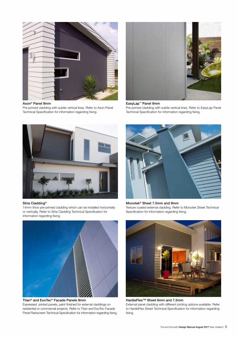
Stria Cladding®
14mm thick pre-primed cladding which can be installed horizontally or vertically. Refer to Stria Cladding Technical Specification for information regarding fixing.

6 Fire and Acoustic Design Manual August 2017 New Zealand
3.1 INTERNAL FIRE RATED WALLS
INTERNAL 30 MINUTE TWO WAY FIRE RATED AND ACOUSTIC SYSTEM
SYSTEM ARRANGEMENTJAMES HARDIE SYSTEM NUMBER
STUD DEPTH (MM)
FRRSTC RANGE
PAGE
JHITVV30 90 30/30/30 41 – 45 17
JHITGV30 90 30/30/30 39 18
INTERNAL 60 MINUTE TWO WAY FIRE RATED AND ACOUSTIC SYSTEM
JHITVV60 90 60/60/60 41 – 45 19
JHITdVV60 90 x 2 60/60/60 58 20
JHITGV60 90 60/60/60 42 – 44 21
3 System index
The following table gives the key information regarding different fire rated and acoustic systems provided in this manual and indicates the page numbers where more descriptive information can be found. All the fire rated systems given in these tables are two way fire rated systems. The information under the 'Reference' column refers to BRANZ report, assessment, or opinion which confirms the fire performance of a system.

Fire and Acoustic Design Manual August 2017 New Zealand 7
3.2 EXTERNAL FIRE RATED WALLS
EXTERNAL 30 MINUTE TWO WAY FIRE RATED AND ACOUSTIC SYSTEM
SYSTEM ARRANGEMENTJAMES HARDIE SYSTEM NUMBER
STUD DEPTH (MM) (MIN)
FRRSTC RANGE
PAGE
JHETGJ30 90 30/30/30 40 – 48 23
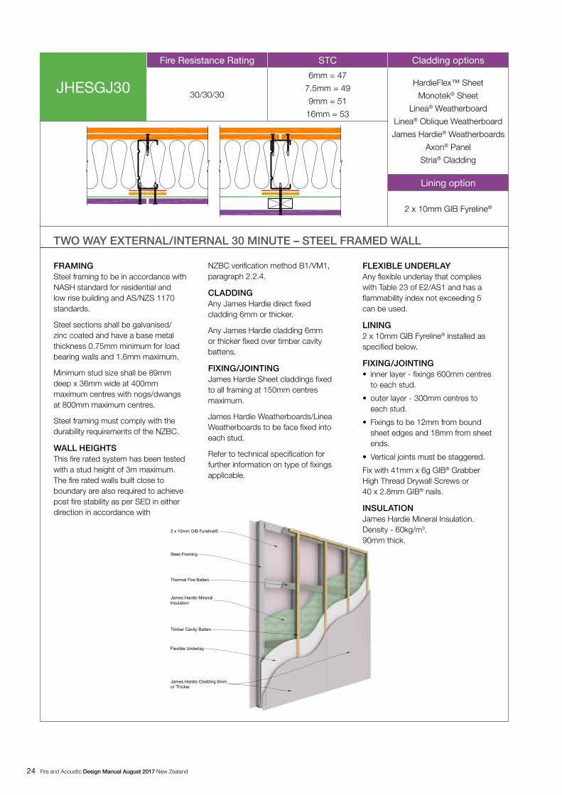
JHESGJ30 89 30/30/30 47 – 53 24
EXTERNAL 60 MINUTE TWO WAY FIRE RATED AND ACOUSTIC SYSTEM
JHETJJ60 90 60/60/60 43 – 47 25
JHETGJ60 90 60/60/60 44 – 47 26
JHESGJ60 89 60/60/60 50 – 54 27
EXTERNAL 90 MINUTE TWO WAY FIRE RATED AND ACOUSTIC SYSTEM
JHETGL90 90 90/90/90 49 28

8 Fire and Acoustic Design Manual August 2017 New Zealand
3.4 FLOORING/CEILINGS FIRE RATED SYSTEMS
SYSTEM ARRANGEMENT JAMES HARDIE SYSTEM NUMBER
FLOOR JOIST DEPTH (MM)
FRR STC/IIC PAGE
JHFTGS30 232 30/30/30 46/33 38
JHFTGS60 235 60/60/60 47/37 39
JHFTGSd60 (cradle) 355 60/60/60 67/57 40
3.3 RAB BOARD FIRE RATED SYSTEMS
SYSTEM ARRANGEMENT JAMES HARDIE SYSTEM NUMBER
STUD DEPTH (MM) (MIN)
FRR STC RANGE
PAGE
JHETGR30c (CLD batten)
90 30/30/30 47 30
JHETGR60c (CLD batten)
90 60/60/60 47 31
JHETGR30a 90 30/30/30 47 32
JHETGR60a 90 60/60/60 47 33
JHETRR30 90 30/30/30 43 34
JHETRR60 90 60/60/60 43 35
JHETGR30b 90 30/30/30 47 36

Fire and Acoustic Design Manual August 2017 New Zealand 9
4 How to use this manual
4.2 COLOUR LEGENDSection drawings have been used in each table using the following colour legend.
4.3 JAMES HARDIE FIRE AND ACOUSTIC SYSTEM DESCRIPTION
A comprehensive range of FRR timber framed and steel framed wall systems are included in this manual.
Each FRR system is identified by unique nomenclature preceded by the letters JH (e.g.JHETJJ60) to identify it as one of the James Hardie fire resistance rated wall systems.
The explanation of system nomenclature used is as follows:
• After JH the first letter defines the application I — Interior system only E — Exterior system only F — Floor system only
• After JH the second letter describes the framing material used with a subscript, “d” denoting double studs. T — timber frame S — steel frame
• After JH, the third and fourth letter describes the material used on each side respectively. A subscript “g” identifies the James Hardie product is fixed over plasterboard on both sides. J is used to indicate the use of a James Hardie product in a FRR system.
The following letters may be used to generate a unique number to fully describe a cladding or a lining product used in a FRR system:J — Any James Hardie cladding or lining material as per the
scope of this manualR — RAB BoardX — HardieFlex SheetM — Monotek Sheet T — Titan Façade Panel A — Axon PanelL — Linea WeatherboardW — James Hardie Weatherboards V — Villaboard LiningG — GIB® Plasterboard (G is generally used in James Hardie
system to identify the use of a GIB® product). S — Secura Interior Flooring
The last two digits indicate the fire resistance rating in minutes.
Returning to the earlier example, JHETJJ60 means this is a James Hardie external fire rated system that uses a standard timber frame with a James Hardie cladding on one face and a James Hardie lining on the other face and the fire rating achieved is up to 60 minutes.
4.4 STC AND Rw Tested or modelled Rw and STC data is indicated in the shaded cells provided for each system. Refer to section 7.12 and 7.13 for the description of methods used to calculate the acoustic performance.
4.5 R-VALUESR-values provided in this manual for external walls have been calculated considering the thermal conductivity of each material and their thickness used in the construction of a wall. The insulation specified in external fire rated systems is a minimum requirement to achieve the desired fire rating performance. For options that would only marginally increase the R-value (e.g.1.5mm increased cladding sheet thickness) has been ignored and the lowest value is presented for simplicity.
The fire rated systems, where a fibreglass R2.2 insulation has been specified, can be replaced with a higher R-value fibreglass insulation material to achieve higher insulation (R-value) requirements.
4.6 WALL WIDTHWall thickness data has been presented for comparative purposes. This is a theoretical figure which excludes construction tolerances and finishes. The nominal wall width figure is based on the product thickness used on each side of the wall.
4.7 WALL HEIGHTUsing 90 x 45mm SG8 timber frame a maximum wall height up to 3m can be achieved.
For maximum wall height in relation to boundary fire rated walls, refer to Figures 1, 3, 4, 5 and 6.
For wall heights more than 3m contact James Hardie for further SED assistance.
4.1 TABLE DATA
The following table explains how to read the information provided for each system:
WALL SECTION
FRR SOUND ATTENUATION DATA
OT
HE
RIN
FO
RM
ATIO
N
SYSTEM NUMBER
FIRE RETARDANT FLEXIBLE UNDERLAY
THERMAL FIRE BATTENS
J = ANY JAMES HARDIE CLADDING OR LINING PER SCOPE
V = VILLABOARD® LINING
G = GIB Fyreline®
RAB® BOARD
Non James Hardie Exterior Cladding complying with C Clause
OP
TIO
NS

10 Fire and Acoustic Design Manual August 2017 New Zealand
5 Design guideline
FOR EXTERNAL WALLS:• Minimum framing size as per figures 1, 3,4, 5 or 6.
• Maximum stud spacing as per figures 1, 3, 4, 5 or 6.
• Maximum nogs / dwangs spacing of 800mm.
• Minimum framing depth as per fire and acoustic system selected or the structural requirements whichever is greater.
• All sheet edges must be supported by framing timber.
• Timber framing treatment to comply with the minimum requirements of NZS 3602.
FOR FLOORS:• Minimum 45mm wide floor joists shall be used.
• Strutting of floor joists is required as per NZS 3604.
• Bottom plate fixing in timber floors must penetrate through floor into joists or solid blocking. Refer to Figures 5 and 6.
5.5 STEELSteel framing for fire rated walls must be in accordance with NASH standard for residential and low rise buildings and AS/NZ 1170 standards. The framing shall also meet the following requirements:
• Steel sections shall be galvanized/zinc coated and have a base metal thickness (BMT) 0.55mm minimum for non-load bearing walls and 0.75mm minimum for load bearing walls and 1.6mm maximum.
• The minimum size for steel stud framing to be used in external walls shall be minimum 89mm deep x 36mm wide.
• Maximum stud spacing 400mm c/c.
• Maximum nogs / dwangs spacing 800mm c/c.
• Steel frame must comply with the durability requirements of NZBC.
• For jointing of the flat sheet products, double studs securely fastened together must be provided where a higher framing width is required. All sheet edges must be supported by framing.
Steel sections thicker than those sound tested may adversely affect the predicted sound ratings of a system.
Emergency fire load capacities for steel framed walls require special calculation. Refer to section 6.2 for further information.
All steel framing must be used according to their manufacturer’s instructions. Steel framing properties vary considerably depending upon the grade of steel used. It is the designer’s responsibility to ensure the type of framing selected is fit for purpose and suitable to carry design loads.
Expressed or open jointed cladding must not be used over steel frame.
5.6 STRUCTURAL STEEL MEMBERS IN FIRE RATED WALL
When structural steel members are located inside the fire rated wall cavity such as columns, or beams in a floor/ceiling cavity, these structural members must be independently fire rated with e.g. Intumescent paints. The temperatures inside the cavities can rise above the critical temperature levels for structural
5.1 GENERALTo achieve the performance levels as described in each system, all materials as specified in the system must be used. The basic information regarding the materials to be used can be found in the individual system, section 8 for internal walls and section 9 for external walls. Information about James Hardie materials are outlined in various tables.
The following section outlines the minimum specifications of other related components.
5.2 BOUNDARY WALL – POST FIRE STABILITY
The fire rated walls built close to boundary are required to achieve post fire stability as per section 2.2.4 of B1/VM1 of the NZBC. James Hardie has developed a few design solutions for concrete slab and timber foundations.
The bottom plate of these walls can be fixed in accordance with Figures 1, 2, 3, 4, 5 and 6 of this design manual using Pryda Brace Anchor on either side of the stud. These fixings ensure that when a boundary wall is exposed to post fire face loads, it doesn’t collapse in any direction. Contact the project structural engineer for an alternate design to achieve post fire stability if the published solutions are not suitable for the project.
Note: Post fire stability for steel framing must be as per SED.
5.3 FRAMINGThe frame sizes and spacing mentioned in this manual are a minimum requirement. Bigger framing sections required to suit a proprietary cladding system or to suit higher wind pressures, will not affect the FRR, provided that the other system requirements presented in this manual are adhered to.
Higher levels of timber treatments or steel coating to enhance their durability will not alter the fire or acoustic performance of the systems.
Sheet set-out must be determined by the designer including the location of all expansion and control joints to enable correct framing set-out (these must be in accordance with the relevant James Hardie product literature).
5.4 TIMBER Timber framing must either be in accordance with NZS 3604 or in accordance with specific engineering design (SED) as per AS/NZS 1170 and NZS 3603 standards. The stud, nogs / dwangs and floor joist spacing, timber size must meet the following minimum requirements:
FOR INTERNAL WALLS:• Minimum framing of 90 x 45mm shall be used.
• Maximum stud spacing 600mm.
• Maximum nogs / dwangs spacing of 800mm.
• Minimum framing depth as per fire and acoustic system selected or the structural requirements whichever is greater.
• All sheet edges must be supported by framing timber.
• Timber framing treatment to comply with the minimum requirements of NZS 3602.
• When framing at 140 x 45mm the maximum stud spacing 600mm.

Fire and Acoustic Design Manual August 2017 New Zealand 11
steel members resulting in premature buckling. Therefore by containing the structural steel members within a fire rated system, it cannot be automatically assumed that a structural steel member will achieve the structural rating of the fire rated system within which it is contained.
5.7 INSULATIONFibreglass InsulationWhere R2.2 fibreglass insulation is specified in a system, any brand of R2.2 fibreglass insulation which weighs 14–18kg/m3 may be used. This insulation can be substituted with a higher R-value fibreglass insulation to achieve higher insulation requirements.
James Hardie Mineral InsulationIn a fire rated system where a mineral insulation is specified, only James Hardie Mineral Insulation must be used. James Hardie Mineral Insulation cannot be substituted with any other insulation material.
Also refer to clause H1 of the NZBC for further information on construction R-value requirements.
5.8 FLEXIBLE UNDERLAY OR RIGID AIR BARRIER
All external walls must have a flexible underlay or a rigid air barrier installed beneath the claddings.
In a FRR system, any flexible underlay that complies with Table 23 of E2/AS1 and has a Flammability Index not exceeding 5, when tested to AS 1530.2 may be used.
James Hardie RAB Board will provide superior thermal insulation, air tightness performance when compared with flexible underlays.
Installation of a flexible underlay or rigid air barrier must be in accordance with their manufacturer’s recommendations and this manual.
RAB Board can be used to achieve the published fire ratings in James Hardie systems where 6mm or thicker James Hardie cladding is specified.
5.9 EXPANSION AND CONTROL JOINTSExpansion joints are generally required for long continuous walls/structures and need to be specified by the project engineer. All expansion joints must extend through the cladding and wall framing.
The control joints provided in certain types of cladding or lining products are a necessity to maintain the system’s integrity and must be formed as per the product’s technical literature.
Some common construction details can be found in section 13 of this manual.
5.10 CONTROL JOINTSHorizontal control joints in claddings shall be provided at all floor joist levels as per the relevant James Hardie product technical specification.
Vertical control joints must be installed as per the James Hardie product technical literature. It is not necessary for all claddings to have vertical control joints e.g. Linea Weatherboard and James Hardie Weatherboards do not require vertical control joints.
Villaboard Lining control joints must be provided as recommended in the Villaboard Lining technical literature.
5.11 CLADDING/LINING LAYOUT AND FIXINGS
The product layout and its installation must be in accordance with the relevant James Hardie product literature for the cladding / lining selected.
The cladding/lining fixings must be as per the information below. Refer to relevant James Hardie product technical literature for further installation details:
• Villaboard Lining fixed at 150mm centres maximum as per Villaboard Lining Installation Manual. When Villaboard Lining is installed over plasterboard, the fixing must be increased in length by the thickness of the plasterboard.
• RAB Board fixed at 150mm centres maximum as per James Hardie Rigid Air Barriers Installation Manual.
• HardieFlex Sheet fixed at 150mm centres maximum. Refer to HardieFlex Sheet Technical Specification for further information.
• Monotek Sheet fixing not exceeding 150mm centres. Refer to Monotek Sheet Technical Specification for further information.
• Linea Weatherboard face fixed at each stud. Refer to Linea Weatherboard Technical Specification.
• Linea Oblique Weatherboard fixed at each stud. Refer to Linea Oblique Weatherboard technical specification.
• Titan and ExoTec Facade Panel fixed at 150mm centres maximum. Refer to Titan and ExoTec Facade Panel Rainscreen Technical Specification (Timber Cavity Battens).
• When installing Titan Facade Panel, Stria Cladding, EasyLap Panel or Axon Panel over CLD Structural Cavity Battens, RAB Board must be used to achieve fire ratings.
• James Hardie Weatherboards fixed at each stud. Refer to James Hardie Weatherboards Technical Specification.
• Axon Panel fixed at 150mm centres maximum. Refer to Axon Panel Technical Specification.
• GIB Fyreline® fixed as per table below and within this design guide.
Fixing claddings / linings to steel framing requires a steel screw which should be selected considering the thickness of cladding, steel frame and thermal fire batten. The minimum penetration in steel frame must be 15mm.
All FRR systems must be mechanically fixed.
All bracing systems must be fixed in accordance with the James Hardie Bracing Design Manual for the selected bracing system.
James Hardie cladding or lining products can be used to achieve fire rating and structural bracing simultaneously.

12 Fire and Acoustic Design Manual August 2017 New Zealand
GIB FYRELINE® FIXING REQUIREMENTS
• 300mm centre around the sheet perimeter and intermediate studs
• Fixings to be 12mm from bound sheet edges and 18mm from sheet ends
TIMBER FRAMING
10mm GIB Fyreline®
41mm x 6g GIB® Grabber® High Thread Drywall Screws or 40 x 2.8mm GIB® nails
13mm GIB Fyreline®
41mm x 6g GIB® Grabber® High Thread Drywall Screws or 40 x 2.8mm GIB® nails
16mm GIB Fyreline®
51mm x 7g GIB® Grabber® High Thread Drywall Screws
STEEL FRAMING
Inner layer 25mm x 6g GIB® Grabber® Drywall Self Tapping Screws
Outer layer 10mm GIB® Fyreline®
32mm x 6g GIB® Grabber® Drywall Self Tapping Screws
Outer layer 13mm GIB® Fyreline®
41mm x 6g GIB® Grabber® Drywall Self Tapping Screws
5.12 COATINGS AND FINISHESAll James Hardie cladding systems require protective coatings to meet the NZBC requirements. Refer to relevant James Hardie technical literature for the product selected. All claddings must be maintained in accordance with product literature. Also refer to coating manufacturer’s recommendations.
For FRR systems with surface finishes over 1mm thick, designers must ensure that the finishes comply with the requirements of Section 5.8 clause C/AS2 to C/AS7 of the NZBC.
James Hardie claddings have been tested and assessed as ‘Non-Combustible’ materials and meet the requirements of clause C3.7 of the NZBC.
6 NZBC considerations
The following performance issues have been considered when designing James Hardie Fire and Acoustic systems. Only a brief outline of the key areas in the NZBC that need to be considered when selecting fire and acoustic systems are provided in this document. It is the designers’ responsibility to familiarise themself with the requirements of the NZBC and select the correct system for the project. Designers need to be particularly familiar with the Approved Documents for the NZBC Fire Safety Clause C to determine fire safety requirements to be followed for their project.
6.1 STRUCTUREGeneral structural requirements for framing have been covered under the framing section of this manual.
6.2 LOAD BEARING OF WALLSRefer to NZS 3604 for framing size and wall height for load bearing and non-load bearing walls. Beyond these limits a specific engineering design is required.
The information about structural loading capacity achieved during a fire test is available to engineers using AS/NZS 1170 design standards, Ask James Hardie on 0800 808 868 for further information.
The load bearing of the steel framed walls are either based on actual test data or assessments that restricts the temperature rise of steel stud sections. To make accurate predictions the information about load bearing capacity of a steel stud at ambient temperatures and applied load during a fire test is required.
The fire rating of a load bearing steel frame wall can be calculated by referring to a non load bearing system information as per the following equation. You can also refer to BRANZ ‘Design of Light Framed Walls for Fire Resistance’ bulletin no.138 for further information.
FRR (LB) = FRR (NLB) x (1 – Applied Load KN/stud / Capacity KN/stud) x FRR (NLB).
WHERE;Capacity — is the normal design load bearing capacity of steel stud at ambient temperatures.
Applied load — is load at the time of fire.
FRR (NLB) — is the FRR of the initial system in minutes selected.
FRR (LB) — is the calculated FRR of the load bearing system.
6.3 BRACINGThe bracing systems specified in James Hardie Bracing Design Manual can easily be combined with the fire and acoustic systems by adhering to the details outlined for the relevant bracing and fire and acoustic systems.
Bracing cannot be achieved when James Hardie claddings/pre-cladding are fixed with screws or when steel framing is used.
6.4 DURABILITYWhen fire rated systems are combined with bracing systems then the durability of the components used in the system must meet a 50 years durability criteria of Clause B2 of the NZBC.
Exposure conditions and nail selection prescribed by NZS 3604
NAIL MATERIAL
Zone D Zone C outside sea spay zone and Zone B and geothermal hot spots
Bracing - all zones
Grade 316 Stainless
Hot-dipped galvanised or 316 stainless
Grade 316 Stainless

Fire and Acoustic Design Manual August 2017 New Zealand 13
In addition to James Hardie specifications, particular attention must be given to adhere with project design advice and the manufacturers instructions to achieve satisfactory durability of performance materials.
6.5 FIRE PERFORMANCETo determine the fire performance required from various walls and floor/ceiling elements of a building, the designer needs to consider the Approved Documents — ‘Protection from Fire’ Clause C of the NZBC. A fire engineer may be required to evaluate the fire safety requirements for a building depending upon its type/scope and the user group etc.
6.6 FIRE RESISTANCEWorking through the Approved Documents will determine the fire resistance rating required for walls that separates the fire cells. These ratings are expressed as Fire Resistance Rating (FRR) of a wall in minutes. Most fire rated systems included in this publication round the values back to the nearest 15 minutes. The fire engineers may occasionally need to use the actual value in some applications. If this information is required, Ask James Hardie on 0800 808 868.
In the event of a fire, the fire walls provide the occupants with sufficient time to escape to safety, prevent spread of fire to neighbouring property, and allow fire extinguishing operations to be completed by ensuring the wall maintains sufficient Stability, Integrity and Insulation for that period.
If the project requires a wall to achieve a FRR of 60/60/60 (i.e. Stability/Integrity/Insulation) the wall will have the following characteristics:
• The first 60 figure describes the wall’s structural stability requirement for 60 minutes. Within this period the wall must support the structure and other fire rated elements within the same or other fire cells. A dash here indicates the wall is not a structural wall (this is typical for non-load bearing systems such as partition walls).
• The second 60 figure describes the wall’s integrity requirement for 60 minutes. During this period the hot gases or flames can not pass through the wall to either side. After this period a failure has occurred as the wall system under test develops cracks or openings through which hot gases and smoke can pass.
• The third 60 figure describes the wall’s insulation requirement for 60 minutes. After this period a failure has occurred in the wall system under test, when:
a) the average temperature of the unexposed surface of the test specimen increases by more than 140˚C above the initial temperature, or
b) the temperature at any point on the unexposed surface increases by more than 180˚C above the initial temperature.
A dash here would indicate that no insulation rating as temperatures are higher than outlined early in the test. Such a system is allowed in external FRR walls that are sufficiently spaced from boundaries.
The James Hardie Fire and Acoustic systems allow a wide range of framing methods and architectural systems to achieve FRR
from 30/30/30 to 90/90/90. When specific fire safety design is required for a specialist application, fire engineers may Ask James Hardie on 0800 808 868 for further information.
6.7 INTERNAL LININGS GROUP NUMBERSThe internal lining materials are required to be tested as per ISO 9705 or ISO 5660 in order to identify their ‘Group Number.’
All James Hardie internal linings such as Villaboard Lining and HardieGroove Lining have been tested/assessed by BRANZ and they have a ‘Group Number 1-S’. Note that this classification only applies to James Hardie fibre cement lining products without paint or wet finish. Contact the surface finishes supplier for Group Number information about their product.
Our prefinished linings such as HardieGlaze Lining, Invibe panel and Inraw panel have also been tested/assessed and they have a ‘Group Number 1-S’. This means that James Hardie lining products are suitable for use as internal linings in exitways and all occupied spaces in schools, hospitals, detention centres, offices, hotels, motels and apartments type buildings etc.
‘Group Number 1-S’ is the highest performance expectation under ‘Part 4. Control of Internal Fire and Smoke Spread’ clause C/AS2 to C/AS7 of the NZBC. It means a James Hardie product can be specified for use in any risk group application.
6.8 NON-COMBUSTIBLE JAMES HARDIE CLADDINGS
James Hardie cladding products i.e. Linea Weatherboard, Linea Oblique Weatherboard, James Hardie Weatherboard, Stria Cladding, Titan Façade Panel, Axon Panel, ExoTec Facade Panel, Monotek Sheet, HardieFlex Sheet and its rigid air barrier products have been tested and assessed by BRANZ for their ‘Peak Heat Release Rates’ and ‘Total Heat Release Rates’ and are classified as ‘Non-Combustible’ materials.
James Hardie fibre cement products are suitable for use in residential/commercial building applications where non-combustible materials are required to control the vertical fire spread through external walls. The peak heat release rate and total heat release rate of James Hardie claddings have been tested and these rates fall well under those specified in Section 5.8.1 (a) of C/AS2-7 and meet the requirements to control the external fire spread.
6.9 VERTICAL FIRE SPREADAccording to E2/AS1 wall claddings are required to be installed either direct fixed to the framing or over the cavity battens depending on the risk score. The fire ratings published in this document are not affected whether the James Hardie cladding is direct fixed or fixed over a drained cavity.
When using the cavity construction method in mixed use buildings with different tenancies one above the other e.g. apartments, offices, retail etc, the external cladding systems must not allow vertical fire spread through the cavity. The cavity behind the claddings is blocked off by running a horizontal batten at the floor level i.e. at the boundary of two fire cells and a ‘Z’

14 Fire and Acoustic Design Manual August 2017 New Zealand
flashing is installed. Inter-storey cladding junction details have been provided in this literature to stop vertical fire spread. Refer to Figure 6.
6.10 INTERNAL MOISTUREThe FRR system published in this literature sets a minimum requirement of R-value for bulk insulation to be used to achieve the fire ratings published in this literature.
The E3 — ‘Internal Moisture’ and H1 — ‘Energy Efficiency’ clauses of the NZBC require the external walls of most buildings to have minimum R-values as per the NZS 4218 to prevent condensation and control the energy losses.
6.11 THERMAL PERFORMANCEThe R-values provided for different systems has been calculated for the complete wall construction using ‘Verification Method’ NZS 4214 and James Hardie Mineral Insulation actual test data. The calculation is based on studs at 400mm centres maximum and nogs at 800mm centres maximum.
James Hardie Mineral Insulation has been tested at BRANZ to verify its physical properties and the tests indicate the following thermal resistance value.
James Hardie Mineral Insulation 90mm = 2.54m2K/W.
The density of this product is @ 60kg/m3.
6.12 ACOUSTIC PERFORMANCE‘Airborne and Impact Sound - G6’ an Approved Document of NZBC requires that ‘buildings shall be provided with adequate noise control in common walls, floors and other elements between occupancies, habitable spaces and other occupancies or common spaces’. The performance criteria requires that the sound transmission class (STC) of walls be no less than 55 and the Impact Insulation Class (IIC) for floors be no less than 55.
The NZBC performance criteria set a minimum requirement which may not be adequate for certain types of multi unit dwelling. Similarly many external walls may need better sound attenuation according to occupants and Resource Management Act requirements. James Hardie products can be used to achieve high sound attenuation ratings and values are presented in this manual for a range of fire rated and acoustic systems. This will help the designers to make an informed decision on the most convenient way to improve noise control for a wide range of internal and external wall applications.
If attention is paid in eliminating structural bridging at location of services, flanking paths and quality of workmanship, performance laboratory results may be achieved on site. There are a number of details in section 13 of this manual to assist designers.
Designers can be assured of getting better onsite results if they specify systems that have higher initial ratings and are simple to construct. Appliances, TVs and speakers should not be mounted on or near inter tenancy walls to avoid transmission of sound by vibration into the structure.
6.13 AIRBORNE SOUNDThe New Zealand Standards authority published AS/NZS 1276.1 (ISO 717-1) for the calculation of Rw and Rw, tr (weighted sound reduction indices) values for airborne sound attenuation. These values are derived by testing and calculation in a similar way as the STC values are calculated and are an international update of this older sound attenuation rating system.
Generally, but not always, Rw ratings are slightly more difficult to achieve and are more conservative and give a lower value than the STC rating for a given construction. This is because they consider a broader spectrum of noise with emphasis on the more difficult to manage lower frequencies. The Rw value can also be used as a reference for attenuating some forms of external noise. Rw value testing can also be expanded to cover a different band of external noise sources and is then denoted by the additional subscript tr. Depending on the ISO document this can be written as Rw+Ctr, Rtr,w and Rw, tr.
This manual has both Rw and STC values for internal and external systems. External noise control in an application generally falls under the Resource Management Act and little published guidance on how to determine effective sound attenuation for external walls has been available. The acoustic designer must consider all sound flanking paths for effective external noise control in a project.
6.14 IMPACT SOUNDAn impact sound performance criterion as per the NZBC is applicable to intertenancy floor systems. James Hardie products such as Secura™ Interior Flooring have been commonly used in floors by acoustic engineers to improve its impact sound performance which is measured in IIC. The sound attenuation performance of ceilings is measured in STC. The IIC and STC for some common floor / ceiling systems have been given in the system details provided in this manual.
6.15 TESTS AND OPINIONSGENERALJames Hardie continuously develops and introduces new systems and reserves the right to improve those presented in this manual.
FIREJames Hardie Fire and Acoustic systems have been tested at BRANZ or have been developed using the test data from various fire tests conducted and by the opinion of qualified fire engineers.
The reference number of tests or opinion/assessments have been provided in Tables 4.1, 4.2 and 4.3.
SOUNDWhere required for compliance with clause G6 of the NZBC (STC > 55) James Hardie Fire and Acoustic systems have been tested at the Acoustic Testing Service, University of Auckland, or have been conservatively derived by technical opinion from acoustic consultant Marshall Day Acoustics. Data values have been either tested or derived from models created from the test data by Marshall Day and Associates and where modelled the data has an expected accuracy of ± 3 points.

Fire and Acoustic Design Manual August 2017 New Zealand 15
6.16 PRODUCT SUBSTITUTIONThe fire and acoustic performance, durability and maintenance requirements of alternative proprietary products cannot be assured by James Hardie. Many apparently identical products were tested and rejected before selection of materials for use in the systems in this manual. Where flexibility is possible it has been reflected in the appropriate system. When a product specified in a system as per this manual is substituted, the performance of the system will be compromised. Therefore the materials specified in the system must not be substituted.
6.17 COMPLIANCEIf the systems are constructed as presented in this manual without substitution or alteration then James Hardie has in the form of this manual presented a producer statement to confirm the performance of systems to the tested standards. James Hardie cannot provide opinions for actual site performance or for systems that deviate from this manual. James Hardie recommends that the specifications materials and systems presented in this manual be strictly adhered to, to avoid building consent and compliance difficulty.
6.18 THERMAL FIRE BATTENFire battens are used on all FRR steel stud systems and must be used between James Hardie cladding and steel framing face. For steel framing in interior/exterior applications the NZBC also requires additional external insulation to achieve adequate thermal resistance. These insulated battens are assembled on site by cutting a 100mm wide strip from 9mm thick Monotek Sheet and adhering a 10mm thick XPS (Extruded Polystyrene) on the face.
All fire battens are fixed horizontally and vertically to all steel faces. All battens must be neatly cut and tightly fitted covering all steel faces. All Thermal Fire Battens must be fitted with the polystyrene to the outside face. The batten is tacked to the steel framing as shown in the following detail.
Battens shall be fixed with a screw to steel frame.
Thermal Fire Batten Fixing
6.19 REFERENCED DOCUMENTS Documents referenced in this manual are current edition and must be complied with.
NZBC APPROVED DOCUMENTSB1 — Structure, B2 — Durability, C — Protection from Fire, C4 — Structural Stability during Fire, E2 — External Moisture, E3 — Internal Moisture, G6 — Airborne and Impact Sound, H1 — Energy Efficiency.
STANDARDSAS/NZS 1276.1 (ISO 717-1), Airborne sound insulation
NZS-AS 1530.2 Test for flammability of materials
AS/NZS 1530.3, Simultaneous determination of ignitability, flame propagation, heat release and smoke release
AS/NZS 3837, Method of test for heat and smoke release rates for materials and products using an oxygen consumption calorimeter
AS/NZS 4200.1, Pliable building membranes and underlay. Part 1, Materials
AS/NZS 4600, Cold formed steel structures
NZS 3602, Timber and Wood Based Products for use in Building
NZS 3603, Timber Structures Standard
NZS 3604, Timber-framed Buildings
NZS 3404, Steel Structural Standard
NZS 1170, Structural Design Actions Standard
NZS 4214, Methods of Determining the Total Thermal Resistances of parts of Buildings

16 Fire and Acoustic Design Manual August 2017 New Zealand
7 Internal walls
7.1 GENERALAll interior walls using Villaboard Lining are impact resistant, moisture resistant and achieve high levels of noise control in a minimal space. With Villaboard Lining FRR systems design flexibility with a variety of finishes is maintained while the FRR is substantially achieved by the complete wall.
Inter-tenancy walls present challenges to both designers and builders. Sufficient consideration to following issues must be given by all involved in the project.
All dimensions shown in tables are in millimetres.
7.2 CONTINUITY AND ISOLATIONTo achieve the required fire protection and sound attenuation on site, it requires informed design by the engineer/designer as he/she deals with the challenges of attaining adequate structural support and bracing while satisfying space utilisation requirements and the separation required for sound control. The engineer must consider the noise transmission issues when dealing with wall junctions/joints and penetrations. An innocuous tie to gain structural stability can significantly reduce a system’s sound attenuation capability.
The designer must also ensure the fundamental rules of continuity and isolation for adequate fire and acoustic performance are adhered to. The builder also needs to adhere to seemingly insignificant details to be assured of performances approaching those achieved in a laboratory.
James Hardie have provided various solutions for achieving structural support, continuity of fire protection and maintaining sound isolation simultaneously, which are detailed in section 13 of this manual.
NZS 4218, Energy Efficiency – Housing and Small Building Envelope.
OTHERSBRANZ, Bulletin 402, Levels of Finish for Flush - Stopped Linings.
“Design of Light Framed Walls for Fire Resistance”, Reprint No.138.
“Design of Load bearing Light Steel Framed Walls for Fire. Resistance”, August 1995, School of Engineering, University of Canterbury, Christchurch.
GIB® Fire Rated Systems, Winstone Wallboards Limited.
GIB® Noise Control Systems, Winstone Wallboards Limited.

Fire and Acoustic Design Manual August 2017 New Zealand 17
JHITVV30Fire Resistance Rating STC Lining options
30/30/306mm = 41
9mm = 45
Villaboard® Lining both sides
FRAMING Timber framing to be in accordance with NZS 3604 or in accordance with specific engineering design complying with AS/NZS 1170 and NZS 3603 standards.
Minimum framing 90 x 45mm at 600mm maximum centres with nogs/dwangs at 800mm maximum centres.
Timber framing treatment to be in accordance with NZBC Acceptable Solution B2/AS1.
WALL HEIGHTSThis fire rated system has been tested with a stud height of 3m maximum.
LININGVillaboard® Lining installed as specified below.
FIXING/JOINTING• 150mm centre around the sheet perimeter and
intermediate studs.
• Fixings to be 12mm from sheet edges and corners 50mm horizontally and 75mm vertically from sheet ends.
Fix with 40 x 2.8mm HardieFlex nails or Villadrive or HardieDrive wood screws.
INSULATIONJames Hardie Mineral Insulation. Density - 60kg/m3. 90mm thick.
For further information refer to the clauses in the Fire and Acoustic Design Manual.
TWO WAY INTERNAL 30 MINUTE – TIMBER FRAMED WALL
6mm or ThickerVillaboard® Lining
Timber Framing
James Hardie MineralInsulation
6mm or ThickerVillaboard® Lining
jhitvv60_ren.dwg

18 Fire and Acoustic Design Manual August 2017 New Zealand
JHITGV30Fire Resistance Rating STC Lining options
30/30/30 39
Villaboard® Lining with 10mm GIB Fyreline®
FRAMING Timber framing to be in accordance with NZS 3604 or in accordance with specific engineering design complying with AS/NZS 1170 and NZS 3603 standards.
Minimum framing 90 x 45mm at 600mm maximum centres with nogs/dwangs at 800mm maximum centres.
Timber framing treatment to be in accordance with NZBC Acceptable Solution B2/AS1.
WALL HEIGHTSThis fire rated system has been tested with a stud height of 3m maximum.
JH LININGVillaboard® Lining 6mm or thicker installed as specified below.
FIXING/JOINTINGJames Hardie Linings fixed into the entire framing using fixings at 150mm centres maximum.
Fix with HardieFlex nails 40 x 2.8mm or Villadrive or HardieDrive wood screws.
LINING10mm GIB Fyreline® installed as specified below.
FIXING/JOINTING• 300mm centre around the sheet
perimeter and intermediate studs.• Fixings to be 12mm from bound
sheet edges and 18mm from sheet ends.
Fix with 41mm x 6g GIB® Grabber High Thread Drywall Screws or 40 x 2.8mm GIB® nails.
INSULATIONR2.2 or higher fibreglass insulation. Density - 14-18kg/m3.
10mm GIB Fyreline®
Timber Framing
R2.2 Fibreglass Insulation
6mm or ThickerVillaboard® Lining
jhitgv30_ren.dwg
For further information refer to clauses within the Fire and Acoustic Design Manual.
TWO WAY INTERNAL 30 MINUTE – TIMBER FRAMED WALL

Fire and Acoustic Design Manual August 2017 New Zealand 19
JHITVV60Fire Resistance Rating STC Lining options
60/60/606mm = 41
9mm = 45
Villaboard® Lining both sides
FRAMING Timber framing to be in accordance with NZS 3604 or in accordance with specific engineering design complying with AS/NZS 1170 and NZS 3603 standards.
Minimum framing 90 x 45mm at 600mm maximum centres with nogs/dwangs at 800mm maximum centres.
Timber framing treatment to be in accordance with NZBC Acceptable Solution B2/AS1.
WALL HEIGHTSThis fire rated system has been tested with a stud height of 3m maximum.
LININGVillaboard® Lining installed as specified below.
FIXING/JOINTING• 150mm centre around the sheet perimeter and
intermediate studs.
• Fixings to be 12mm from sheet edges and corners 50mm horizontally and 75mm vertically from sheet ends.
Fix with 40 x 2.8mm HardieFlex nails or Villadrive or HardieDrive wood screws.
INSULATIONJames Hardie Mineral Insulation. Density - 60kg/m3. 90mm thick.
6mm or ThickerVillaboard® Lining
Timber Framing
James Hardie MineralInsulation
6mm or ThickerVillaboard® Lining
jhitvv60_ren.dwg
For further information refer to the clauses in the Fire and Acoustic Design Manual.
TWO WAY INTERNAL 60 MINUTE – TIMBER FRAMED WALL

20 Fire and Acoustic Design Manual August 2017 New Zealand
JHITdVV60Fire Resistance Rating STC Lining options
60/60/60 9mm = 58
9mm Villaboard® Lining both sides
FRAMING Timber framing to be in accordance with NZS 3604 or in accordance with specific engineering design complying with AS/NZS 1170 and NZS 3603 standards.
Minimum framing 90 x 45mm at 600mm maximum centres with nogs/dwangs at 800mm maximum centres.
Timber framing treatment to be in accordance with NZBC Acceptable Solution B2/AS1.
WALL HEIGHTSThis fire rated system has been tested with a stud height of 3m maximum.
LININGVillaboard® Lining 9mm installed as specified below.
FIXING/JOINTINGJames Hardie Linings fixed into the entire framing using fixings at 150mm centres maximum.
Fix with 40 x 2.8mm HardieFlex nails or Villadrive or HardieDrive wood screws.
INSULATIONR2.2 or higher fibreglass insulation Density - 14-18kg/m3.
James Hardie Mineral Insulation. Density - 60kg/m3. 90mm thick.
STRUCTURAL STABILITYAs per SED or details published by James Hardie.
For further information refer to the clauses in the Fire and Acoustic Design Manual.
TWO WAY INTERNAL 60 MINUTE – TIMBER FRAMED WALL
9mm Villaboard® Lining
Timber Framing
R2.2 Fiberglass Insulation
9mm Villaboard® Lining
James Hardie MineralInsulation
jhitdvv60_ren.dwg

Fire and Acoustic Design Manual August 2017 New Zealand 21
JHITGV60Fire Resistance Rating STC Lining options
60/60/606mm = 42
9mm = 44
Villaboard® Lining with 13mm GIB Fyreline®
FRAMING Timber framing to be in accordance with NZS 3604 or in accordance with specific engineering design complying with AS/NZS 1170 and NZS 3603 standards.
Minimum framing 90 x 45mm at 600mm maximum centres with nogs/dwangs at 800mm maximum centres.
Timber framing treatment to be in accordance with NZBC Acceptable Solution B2/AS1.
WALL HEIGHTSThis fire rated system has been tested with a stud height of 3m maximum.
JH LININGVillaboard® Lining 6mm or thicker installed as specified below.
FIXING/JOINTINGJames Hardie Linings fixed into the entire framing using fixings at 150mm centres maximum.
Fix with 40 x 2.8mm HardieFlex nails or Villadrive or HardieDrive wood screws.
LINING13mm GIB Fyreline® installed as specified below.
FIXING/JOINTING• 300mm centre around the sheet
perimeter and intermediate studs.
• Fixings to be 12mm from bound sheet edges and 18mm from sheet ends.
Fix with 41mm x 6g GIB® Grabber High Thread.
Drywall Screws or 40 x 2.8mm GIB® nails.
INSULATIONJames Hardie Mineral Insulation. Density - 60kg/m3. 90mm thick.
13mm GIB Fyreline®
Timber Framing
James Hardie MineralInsulation
6mm or ThickerVillaboard® Lining
jhitgv60_ren.dwg
For further information refer to the clauses in the Fire and Acoustic Design Manual.
TWO WAY INTERNAL 60 MINUTE – TIMBER FRAMED WALL

22 Fire and Acoustic Design Manual August 2017 New Zealand
8 External walls
The systems presented in the following sections are primarily based on the correct selection of materials.
When using Linea Weatherboards in a fire rated situation the weatherboard must always be face fixed.
All dimensions shown in tables are in millimetres.
GENERALThe external walls are required to be fire rated depending upon the situation when the wall is close to a boundary or a neighbouring property in order to comply with NZBC clause C3. The walls included in this section are two way fire rated load bearing walls as per NZS 3604. Special attention must be paid to junctions and penetrations in external walls. The external claddings may be required to be fixed over a cavity for certain designs and the cavity must not open into the roof space or sub floor space.

Fire and Acoustic Design Manual August 2017 New Zealand 23
JHETGJ30Fire Resistance Rating STC Cladding options
30/30/30 40 – 48HardieFlex™ Sheet
Monotek® Sheet Linea® Weatherboard
Linea® Oblique Weatherboard James Hardie® Weatherboards
Axon® PanelStria® Cladding
Lining option
10mm GIB Fyreline®
10mm GIB Fyreline®
Timber Framing
R2.2 Fibreglass Insulation
Timber Cavity Batten
Fire Retardant FlexibleUnderlay
Timber Cavity Batten
James Hardie Flat Sheet Cladding6mm or Thicker
OR
James Hardie® Weatherboard,Linea® Weatherboard and Linea®Oblique Weatherboard
jhetgj30_tim_bat_ren.dwg
For further information refer to the clauses in the Fire and Acoustic Design Manual.
TWO WAY EXTERNAL/INTERNAL 30 MINUTE – TIMBER FRAMED WALL
FRAMING Timber framing to be in accordance with NZS 3604 or in accordance with specific engineering design complying with AS/NZS 1170 and NZS 3603 standards.
Minimum framing 90 x 45mm at 600mm maximum centres with nogs/dwangs at 800mm maximum centres.
Timber framing treatment to be in accordance with the NZBC Acceptable Solution B2/AS1.
WALL HEIGHTSThis fire rated system has been tested with a stud height of 3m maximum. The fire rated walls built close to boundary are also required to achieve post fire stability in either direction in accordance with the NZBC verification method B1/VM1, paragraph 2.2.4.
Refer to Figure 1, 3, 4, 5 and 6 of the Fire and Acoustic Design Manual for post fire stability design.
CLADDING Any James Hardie direct fixed cladding 6mm or thicker.
Any James Hardie cladding 6mm or thicker fixed over timber cavity battens.
FIXING/JOINTINGJames Hardie Sheet claddings fixed to all framing at 150mm centres.
Linea Weatherboards to be face fixed into each stud.
Refer to technical specification for further information on type of fixings applicable. Also refer to Figures 8 and 9.
FLEXIBLE UNDERLAYAny flexible underlay that complies with Table 23 of E2/AS1 and has a flammability index not exceeding 5 can be used.
LINING10mm GIB Fyreline® installed as specified below.
FIXING/JOINTING• 300mm centre around the sheet
perimeter and intermediate studs.
• Fixings to be 12mm from bound sheet edges and 18mm from sheet ends.
Fix with 41mm x 6g GIB® Grabber High Thread Drywall Screws or 40 x 2.8mm GIB® nails.
INSULATIONR2.2 or higher fibreglass insulation. Density - 14-18kg/m3.
24 Fire and Acoustic Design Manual August 2017 New Zealand
FRAMING Steel framing to be in accordance with NASH standard for residential and low rise building and AS/NZS 1170 standards.
Steel sections shall be galvanised/zinc coated and have a base metal thickness 0.75mm minimum for load bearing walls and 1.6mm maximum.
Minimum stud size shall be 89mm deep x 36mm wide at 400mm maximum centres with nogs/dwangs at 800mm maximum centres.
Steel framing must comply with the durability requirements of the NZBC.
WALL HEIGHTSThis fire rated system has been tested with a stud height of 3m maximum. The fire rated walls built close to boundary are also required to achieve post fire stability as per SED in either direction in accordance with
NZBC verification method B1/VM1, paragraph 2.2.4.
CLADDING Any James Hardie direct fixed cladding 6mm or thicker.
Any James Hardie cladding 6mm or thicker fixed over timber cavity battens.
FIXING/JOINTINGJames Hardie Sheet claddings fixed to all framing at 150mm centres maximum.
James Hardie Weatherboards/Linea Weatherboards to be face fixed into each stud.
Refer to technical specification for further information on type of fixings applicable.
FLEXIBLE UNDERLAYAny flexible underlay that complies with Table 23 of E2/AS1 and has a flammability index not exceeding 5 can be used.
LINING2 x 10mm GIB Fyreline® installed as specified below.
FIXING/JOINTING• inner layer - fixings 600mm centres
to each stud.
• outer layer - 300mm centres to each stud.
• Fixings to be 12mm from bound sheet edges and 18mm from sheet ends.
• Vertical joints must be staggered.
Fix with 41mm x 6g GIB® Grabber High Thread Drywall Screws or 40 x 2.8mm GIB® nails.
INSULATIONJames Hardie Mineral Insulation. Density - 60kg/m3. 90mm thick.
TWO WAY EXTERNAL/INTERNAL 30 MINUTE – STEEL FRAMED WALL
2 x 10mm GIB Fyreline®
Steel Framing
James Hardie MineralInsulation
Thermal Fire Batten
Flexible Underlay
James Hardie Cladding 6mmor Thicker
Timber Cavity Batten
jhesgj30_tim_bat_ren.dwg
JHESGJ30
Fire Resistance Rating STC Cladding options
30/30/30
6mm = 47
7.5mm = 49
9mm = 51
16mm = 53
HardieFlex™ Sheet
Monotek® Sheet
Linea® Weatherboard
Linea® Oblique Weatherboard
James Hardie® Weatherboards
Axon® Panel
Stria® Cladding
Lining option
2 x 10mm GIB Fyreline®

Fire and Acoustic Design Manual August 2017 New Zealand 25
JHETJJ60
Fire Resistance Rating STC Lining/Cladding options
60/60/60
6mm = 437.5mm = 469mm = 47
16mm = 44
Villaboard® Lining one side and JH cladding other
orHardieFlex™ Sheet both sides
Monotek® Sheet both sidesLinea® Weatherboard both
sidesLinea® Oblique Weatherboard
both sidesJames Hardie® Weatherboards
both sidesAxon® Panel both sides
Stria® Cladding both sides
FRAMING Timber framing to be in accordance with NZS 3604 or in accordance with specific engineering design complying with AS/NZS 1170 and NZS 3603 standards.
Minimum framing 90 x 45mm at 600mm maximum centres with nogs/dwangs at 800mm maximum centres.
Timber framing treatment to be in accordance with the NZBC Acceptable Solution B2/AS1.
WALL HEIGHTSThis fire rated system has been tested with a stud height of 3m maximum. The fire rated walls built close to boundary are also required to achieve post fire stability in either direction in accordance with the NZBC verification method B1/VM1, paragraph 2.2.4. Refer to Figure 1, 3, 4, 5 and 6 of the Fire and Acoustic Design Manual for post fire stability design.
CLADDING Any James Hardie direct fixed cladding 6mm or thicker.
Any James Hardie cladding 6mm or thicker fixed over timber cavity battens.
FIXING/JOINTINGJames Hardie Sheet claddings fixed to all framing at 150mm centres maximum.
James Hardie Weatherboards/Linea Weatherboards to be face fixed into each stud.
Refer to technical specification for further information on type of fixings applicable. Also refer to Figures 8 and 9.
FLEXIBLE UNDERLAYAny flexible underlay that complies with Table 23 of E2/AS1 and has a flammability index not exceeding 5 can be used.
Not required when 6mm RAB Board system.
LININGVillaboard® Lining installed as specified below.
FIXING/JOINTING• 150mm centre around the sheet
perimeter and intermediate studs.
• Fixings to be 12mm from sheet edges and corners 50mm horizontally and 75mm vertically from sheet ends.
Fix with 40 x 2.8mm HardieFlex nails or Villadrive or HardieDrive wood screws.
INSULATIONJames Hardie Mineral Insulation. Density - 60kg/m3. 90mm thick.
For further information refer to the clauses in the Fire and Acoustic Design Manual.
TWO WAY EXTERNAL 60 MINUTE – TIMBER FRAMED WALL
James Hardie Lining6mm or Thicker
Timber Framing
James Hardie MineralInsulation
Timber Cavity Batten
Fire retardant flexible underay
James Hardie Flat Sheet Cladding6mm or Thicker
OR
James Hardie® Weatherboard,Linea® Weatherboard and Linea®Oblique Weatherboard
jhetjj60_tim_bat_ren.dwg

26 Fire and Acoustic Design Manual August 2017 New Zealand
JHETGJ60Fire Resistance Rating STC Cladding options
60/60/60 44 – 47 HardieFlex™ Sheet Monotek® Sheet
Linea® Weatherboard Linea® Oblique Weatherboard James Hardie® Weatherboards
Axon® Panel Stria® Cladding
Lining option
13mm GIB Fyreline®
FRAMING Timber framing to be in accordance with NZS 3604 or in accordance with specific engineering design complying with AS/NZS 1170 and NZS 3603 standards.
Minimum framing 90 x 45mm at 600mm maximum centres with nogs/dwangs at 800mm maximum centres.
Timber framing treatment to be in accordance with the NZBC Acceptable Solution B2/AS1.
WALL HEIGHTSThis fire rated system has been tested with a stud height of 3m maximum. The fire rated walls built close to boundary are also required to achieve post fire stability in either direction in accordance with the NZBC verification method B1/VM1, paragraph 2.2.4. Refer to Figure 1, 3, 4, 5 and 6 of the Fire and Acoustic Design Manual for post fire stability design.
CLADDING Any James Hardie direct fixed cladding 6mm or thicker.
Any James Hardie cladding 6mm or thicker fixed over timber cavity battens.
FIXING/JOINTINGJames Hardie Sheet claddings fixed to all framing at 150mm centres maximum.
James Hardie Weatherboards/Linea Weatherboards to be face fixed into each stud.
Refer to technical specification for further information on type of fixings applicable. Also refer to Figures 8 and 9.
FLEXIBLE UNDERLAYAny flexible underlay that complies with Table 23 of E2/AS1 and has a flammability index not exceeding 5 can be used.
LINING13mm GIB Fyreline® installed as specified below.
FIXING/JOINTING• 300mm centre around the sheet
perimeter and intermediate studs.
• Fixings to be 12mm from bound sheet edges and 18mm from sheet ends.
Fix with 41mm x 6g GIB® Grabber High Thread Drywall Screws or 40 x 2.8mm GIB® nails.
INSULATIONJames Hardie Mineral Insulation. Density - 60kg/m3. 90mm thick.
For further information refer to the clauses in the Fire and Acoustic Design Manual.
TWO WAY EXTERNAL/INTERNAL 60 MINUTE – TIMBER FRAMED WALL
13mm GIB Fyreline®
Timber Framing
James Hardie MineralInsulation
Timber Cavity Batten
Fire Retardant FlexibleUnderay
James Hardie Flat Sheet Cladding6mm or Thicker
OR
James Hardie® Weatherboard,Linea® Weatherboard and Linea®Oblique Weatherboard
jhetgj60_tim_bat_ren.dwg

Fire and Acoustic Design Manual August 2017 New Zealand 27
FRAMING Steel framing to be in accordance with NASH standard for residential and low rise building and AS/NZS 1170 standards.
Steel sections shall be galvanised/zinc coated and have a base metal thickness 0.75mm minimum for load bearing walls and 1.6mm maximum.
Minimum stud size shall be 89mm deep x 36mm wide at 400mm maximum centres with nogs/dwangs at 800mm maximum centres.
Steel framing must comply with the durability requirements of the NZBC.
WALL HEIGHTSThis fire rated system has been tested with a stud height of 3m maximum. The fire rated walls built close to boundary are also required to achieve post fire stability in either direction as per SED in accordance with
NZBC verification method B1/VM1, paragraph 2.2.4.
CLADDING Any James Hardie direct fixed cladding 6mm or thicker.
Any James Hardie cladding 6mm or thicker fixed over timber cavity battens.
FIXING/JOINTINGJames Hardie Sheet claddings fixed to all framing at 150mm centres maximum.
James Hardie Weatherboards/Linea Weatherboards to be face fixed into each stud.
Refer to technical specification for further information on type of fixings applicable.
FLEXIBLE UNDERLAYAny flexible underlay that complies with Table 23 of E2/AS1 and has a flammability index not exceeding 5 can be used.
LINING2 x 13mm GIB Fyreline® installed as specified below.
FIXING/JOINTING• Inner layer - fixings 600mm centres
to each stud.
• Outer layer - fixings 300mm centres to each stud.
• Fixings to be 12mm from bound sheet edges and 18mm from sheet ends.
• Veritcal joints must be staggered.
Fix with 41mm x 6g GIB® Grabber High Thread Drywall Screws or 40 x 2.8mm GIB® nails.
INSULATIONJames Hardie Mineral Insulation. Density - 60kg/m3. 90mm thick.
For further information refer to the clauses in the Fire and Acoustic Design Manual.
TWO WAY EXTERNAL/INTERNAL 60 MINUTE – STEEL FRAMED WALL
2 x 13mm GIB Fyreline®
Steel Framing
James Hardie MineralInsulation
Thermal Fire Batten
Flexible Underlay
James Hardie Cladding 6mmor Thicker
Timber Cavity Batten
jhesgj60_tim_bat_ren.dwg
JHESGJ60
Fire Resistance Rating STC Cladding options
60/60/60
6mm = 50
7.5mm = 51
9mm = 51
16mm = 54
HardieFlex™ Sheet
Monotek® Sheet
Linea® Weatherboard
Linea® Oblique Weatherboard
James Hardie® Weatherboards
Axon® Panel
Stria® Cladding
Lining option
2 x 13mm GIB Fyreline®

28 Fire and Acoustic Design Manual August 2017 New Zealand
FRAMING Timber framing to be in accordance with NZS 3604 or in accordance with specific engineering design complying with AS/NZS 1170 and NZS 3603 standards.
Minimum framing 90 x 45mm at 600mm maximum centres with nogs/dwangs at 800mm maximum centres.
Timber framing treatment to be in accordance with the NZBC Acceptable Solution B2/AS1.
WALL HEIGHTSThis fire rated system has been tested with a stud height of 3m maximum. The fire rated walls built close to boundary are also required to achieve post fire stability in either direction in accordance with the NZBC verification method B1/VM1, paragraph 2.2.4.
Refer to Figure 1, 3, 4, 5 and 6 of the Fire and Acoustic Design Manual for post fire stability design.
CLADDING Linea Weatherboard direct fixed. Linea Weatherboard fixed over timber cavity battens.
FIXING/JOINTING Linea Weatherboards to be face fixed into each stud as per technical specification. Also refer to Figure 9.
PRE-CLADDING6mm RAB Board.
FIXING/JOINTINGRAB Board fixed to all framing with fixings at 150mm centres maximum.
Joints taped as per James Hardie Rigid Air Barriers Installation Manual.
LINING16mm GIB Fyreline® installed as specified below.
FIXING/JOINTING• 300mm centre around the sheet
perimeter and intermediate studs.
• Fixings to be 12mm from bound sheet edges and 18mm from sheet ends.
Fix with 41mm x 6g GIB® Grabber High Thread Drywall Screws or 40 x 2.8mm GIB® nails.
INSULATIONJames Hardie Mineral Insulation. Density - 60kg/m3. 90mm thick.
For further information refer to the clauses in the Fire and Acoustic Design Manual.
TWO WAY EXTERNAL/INTERNAL 90 MINUTE – TIMBER FRAMED WALL
16mm GIB Fyreline®
Timber Framing
James Hardie MineralInsulation
Timber Cavity Batten
RAB Board®
Linea® Weatherboard
jhetgl90_tim_bat_ren.dwg
JHETGL90Fire Resistance Rating STC Cladding options
90/90/90 49
Linea® Weatherboard over RAB® Board
Lining option
16mm GIB Fyreline®

Fire and Acoustic Design Manual August 2017 New Zealand 29
9 RAB Board
GENERALWhere a RAB Board is used in lieu of a flexible underlay then the fire rating can be achieved without relying on the cladding product. RAB Board is suitable to achieve a fire rating up to 60 minutes as per fire rated system described below. When RAB Board is used for fire rating, a ‘non-combustible’ cladding material e.g. Monotek Sheet, Linea Weatherboard, Linea Oblique Weatherboard, Stria Cladding, Axon Panel, Titan Facade Panel etc can be used over RAB Board. These claddings can either be direct fixed or fixed onto a cavity batten over RAB Board. The cavity must not open into the roof or sub floor spaces. Special attention must be paid to junctions and penetrations through external walls.
When RAB Board is used in conjunction with Linea Weatherboard cladding, a 90 minute fire rating can be achieved. Refer to JHETGL 90 system for further details.
James Hardie cladding system eg Axon Panel, EasyLap Panel, Titan Façade Panel installed to CLD Structural Cavity Batten in conjunction with RAB Board, are suitable for use in fire rated systems.
Always fix the cladding as per their manufacturers’ recommendations.

30 Fire and Acoustic Design Manual August 2017 New Zealand
FRAMING Timber framing to be in accordance with NZS 3604 or in accordance with specific engineering design complying with AS/NZS 1170 and NZS 3603 standards.
Minimum framing 90 x 45mm at 600mm maximum centres with nogs/dwangs at 800mm maximum centres.
Timber framing treatment to be in accordance with the NZBC Acceptable Solution B2/AS1.
WALL HEIGHTSThis fire rated system has been tested with a stud height of 3m maximum. The fire rated walls built close to boundary are also required to achieve post fire stability in either direction in accordance with the NZBC verification
method B1/VM1, paragraph 2.2.4. Refer to Figure 1, 3, 4, 5 and 6 of the Fire and Acoustic Design Manual for post fire stability design.
CLADDING Axon Panel, EasyLap Panel, Titan Façade Panel fixed to CLD Structural Cavity Batten fixed as per their technical specification.
PRE-CLADDING6mm RAB Board.
FIXING/JOINTINGRAB Board fixed to all framing with fixings at 150mm centres maximum.
Joints taped as per James Hardie Rigid Air Barriers Installation Manual.
LINING10mm GIB Fyreline® installed as specified below.
FIXING/JOINTING• 300mm centre around the sheet
perimeter and intermediate studs.
• Fixings to be 12mm from bound sheet edges and 18mm from sheet ends.
Fix with 41mm x 6g GIB® Grabber High Thread Drywall Screws or 40 x 2.8mm GIB® nails.
INSULATIONR2.2 or higher fibreglass insulation. Density - 14-18kg/m3.
For further information refer to the clauses in the Fire and Acoustic Design Manual.
TWO WAY EXTERNAL/INTERNAL 30 MINUTE – TIMBER FRAMED WALL
10mm GIB Fyreline®
Timber Framing
R2.2 Fibreglass Insulation
70 x 19mm CLD®Structural CavityBatten
RAB® Board
Axon® Panel, EasyLapTM
Panel, Titan® FacadePanel
jhetgr30_cld_bat_ren.dwg
JHETGR30cFire Resistance Rating STC Cladding options
30/30/30 47
Axon® Panel
EasyLap® Panel
Titan® Façade Panel
Lining option
10mm GIB Fyreline®

Fire and Acoustic Design Manual August 2017 New Zealand 31
FRAMING Timber framing to be in accordance with NZS 3604 or in accordance with specific engineering design complying with AS/NZS 1170 and NZS 3603 standards.
Minimum framing 90 x 45mm at 600mm maximum centres with nogs/dwangs at 800mm maximum centres.
Timber framing treatment to be in accordance with the NZBC Acceptable Solution B2/AS1.
WALL HEIGHTSThis fire rated system has been tested with a stud height of 3m maximum. The fire rated walls built close to boundary are also required to achieve post fire stability in either direction in accordance with the NZBC verification
method B1/VM1, paragraph 2.2.4. Refer to Figure 1, 3, 4, 5 and 6 of the Fire and Acoustic Design Manual for post fire stability design.
CLADDING Axon Panel, EasyLap Panel, Titan Façade Panel fixed to CLD Structural Cavity Batten fixed as per their technical specification.
PRE-CLADDING6mm RAB Board.
FIXING/JOINTINGRAB Board fixed to all framing with fixings at 150mm centres maximum.
Joints taped as per James Hardie Rigid Air Barriers Installation Manual.
LINING13mm GIB Fyreline® installed as specified below.
FIXING/JOINTING• 300mm centre around the sheet
perimeter and intermediate studs.
• Fixings to be 12mm from bound sheet edges and 18mm from sheet ends.
Fix with 41mm x 6g GIB® Grabber High Thread Drywall Screws or 40 x 2.8mm GIB® nails.
INSULATIONJames Hardie Mineral Insulation. Density - 60kg/m3. 90mm thick.
For further information refer to the clauses in the Fire and Acoustic Design Manual.
TWO WAY EXTERNAL/INTERNAL 60 MINUTE – TIMBER FRAMED WALL
13mm GIB Fyreline®
Timber Framing
James Hardie MineralInsulation
70 x 19mm CLD®Structural Cavity Batten
RAB® Board
Axon® Panel, EasyLapTMPanel, Titan® FacadePanel
jhetgr60_cld_bat_ren.dwg
JHETGR60cFire Resistance Rating STC Cladding options
60/60/60 47
Axon® Panel
EasyLap® Panel
Titan® Façade Panel
Lining option
13mm GIB Fyreline®

32 Fire and Acoustic Design Manual August 2017 New Zealand
FRAMING Timber framing to be in accordance with NZS 3604 or in accordance with specific engineering design complying with AS/NZS 1170 and NZS 3603 standards.
Minimum framing 90 x 45mm at 600mm maximum centres with nogs/dwangs at 800mm maximum centres.
Timber framing treatment to be in accordance with the NZBC Acceptable Solution B2/AS1.
WALL HEIGHTSThis fire rated system has been tested with a stud height of 3m maximum. The fire rated walls built close to boundary are also required to achieve post fire stability in either direction in accordance with the NZBC verification
method B1/VM1, paragraph 2.2.4. Refer to Figure 1, 3, 4, 5 and 6 of the Fire and Acoustic Design Manual for post fire stability design.
CLADDING Non-combustible cladding as per clause 5.8.1 of C/AS of the NZBC fixed as per their technical specification either on timber cavity batten or direct fixed.
PRE-CLADDING6mm RAB Board.
FIXING/JOINTINGRAB Board fixed to all framing with fixings at 150mm centres maximum.
Joints taped as per James Hardie Rigid Air Barriers Installation Manual.
LINING10mm GIB Fyreline® installed as specified below.
FIXING/JOINTING• 300mm centre around the sheet
perimeter and intermediate studs.
• Fixings to be 12mm from bound sheet edges and 18mm from sheet ends.
Fix with 41mm x 6g GIB® Grabber High Thread Drywall Screws or 40 x 2.8mm GIB® nails.
INSULATIONR2.2 or higher fibreglass insulation. Density - 14-18kg/m3.
For further information refer to the clauses in the Fire and Acoustic Design Manual.
TWO WAY EXTERNAL/INTERNAL 30 MINUTE – TIMBER FRAMED WALL
10mm GIB Fyreline®
Timber Framing
R2.2 Fibreglass Insulation
Timber Cavity Batten
RAB® Board
Cladding as per ManufacturersRecommendations
jhetgr30_tim_bat_ren.dwg
JHETGR30aFire Resistance Rating STC Cladding options
30/30/30 47
A non-combustibe cladding as per C clause
over RAB® Board
Lining option
10mm GIB Fyreline®

Fire and Acoustic Design Manual August 2017 New Zealand 33
FRAMING Timber framing to be in accordance with NZS 3604 or in accordance with specific engineering design complying with AS/NZS 1170 and NZS 3603 standards.
Minimum framing 90 x 45mm at 600mm maximum centres with nogs/dwangs at 800mm maximum centres.
Timber framing treatment to be in accordance with the NZBC Acceptable Solution B2/AS1.
WALL HEIGHTSThis fire rated system has been tested with a stud height of 3m maximum. The fire rated walls built close to boundary are also required to achieve post fire stability in either direction in accordance with the NZBC verification
method B1/VM1, paragraph 2.2.4. Refer to Figure 1, 3, 4, 5 and 6 of the Fire and Acoustic Design Manual for post fire stability design.
CLADDING Non-combustible cladding as per clause 5.8.1 of C/AS of the NZBC fixed as per their technical specification either on timber cavity batten or direct fixed.
PRE-CLADDING6mm RAB Board.
FIXING/JOINTINGRAB Board fixed to all framing with fixings at 150mm centres maximum.
Joints taped as per James Hardie Rigid Air Barriers Installation Manual.
LINING13mm GIB Fyreline® installed as specified below.
FIXING/JOINTING• 300mm centre around the sheet
perimeter and intermediate studs.
• Fixings to be 12mm from bound sheet edges and 18mm from sheet ends.
Fix with 41mm x 6g GIB® Grabber High Thread Drywall Screws or 40 x 2.8mm GIB® nails.
INSULATIONJames Hardie Mineral Insulation. Density - 60kg/m3. 90mm thick.
For further information refer to the clauses in the Fire and Acoustic Design Manual.
TWO WAY EXTERNAL/INTERNAL 60 MINUTE – TIMBER FRAMED WALL
13mm GIB Fyreline®
Timber Framing
James Hardie MineralInsulation
Timber Cavity Batten
RAB® Board
Cladding as per ManufacturersRecommendations
jhetgr60_tim_bat_ren.dwg
JHETGR60aFire Resistance Rating STC Cladding options
60/60/60 47
A non-combustibe cladding as per C clause
over RAB® Board
Lining option
13mm GIB Fyreline®

34 Fire and Acoustic Design Manual August 2017 New Zealand
FRAMING Timber framing to be in accordance with NZS 3604 or in accordance with specific engineering design complying with AS/NZS 1170 and NZS 3603 standards.
Minimum framing 90 x 45mm at 600mm maximum centres with nogs/dwangs at 800mm maximum centres.
Timber framing treatment to be in accordance with the NZBC Acceptable Solution B2/AS1.
WALL HEIGHTSThis fire rated system has been tested with a stud height of 3m maximum. The fire rated walls built close to boundary are also required to achieve post fire stability in either direction in accordance with the NZBC verification
method B1/VM1, paragraph 2.2.4. Refer to Figure 1, 3, 4, 5 and 6 of the Fire and Acoustic Design Manual for post fire stability design.
CLADDING Non-combustible cladding as per clause 5.8.1 of C/AS of the NZBC fixed as per their technical specification either on timber cavity batten or direct fixed.
PRE-CLADDING6mm RAB Board.
FIXING/JOINTINGRAB Board fixed to all framing with fixings at 150mm centres maximum.
Joints taped as per James Hardie Rigid Air Barriers Installation Manual.
INSULATIONJames Hardie Mineral Insulation. Density - 60kg/m3. 90mm thick.
For further information refer to the clauses in the Fire and Acoustic Design Manual.
TWO WAY EXTERNAL/EXTERNAL 30 MINUTE – TIMBER FRAMED WALL
JHETRR30Fire Resistance Rating STC Cladding options
30/30/30 43
A non-combustibe cladding as per C clause
over RAB® Board
RAB® Board
Timber Framing
James Hardie MineralInsulation
Timber Cavity Batten
RAB® Board
Cladding as per ManufacturersRecommendations
jh02 jhetgr60_tim_bat_ren.dwg

Fire and Acoustic Design Manual August 2017 New Zealand 35
FRAMING Timber framing to be in accordance with NZS 3604 or in accordance with specific engineering design complying with AS/NZS 1170 and NZS 3603 standards.
Minimum framing 90 x 45mm at 600mm maximum centres with nogs/dwangs at 800mm maximum centres.
Timber framing treatment to be in accordance with the NZBC Acceptable Solution B2/AS1.
WALL HEIGHTSThis fire rated system has been tested with a stud height of 3m maximum. The fire rated walls built close to boundary are also required to achieve post fire stability in either direction in accordance with the NZBC verification
method B1/VM1, paragraph 2.2.4. Refer to Figure 1, 3, 4, 5 and 6 of the Fire and Acoustic Design Manual for post fire stability design.
CLADDING Non-combustible cladding as per clause 5.8.1 of C/AS of the NZBC fixed as per their technical specification either on timber cavity batten or direct fixed.
PRE-CLADDING6mm RAB Board.
FIXING/JOINTINGRAB Board fixed to all framing with fixings at 150mm centres maximum.
Joints taped as per James Hardie Rigid Air Barriers Installation Manual.
INSULATIONJames Hardie Mineral Insulation. Density - 60kg/m3. 90mm thick.
For further information refer to the clauses in the Fire and Acoustic Design Manual.
TWO WAY EXTERNAL/EXTERNAL 60 MINUTE – TIMBER FRAMED WALL
JHETRR60Fire Resistance Rating STC Cladding options
60/60/60 43
A non-combustibe cladding as per C clause
over RAB® Board
RAB® Board
Timber Framing
James Hardie MineralInsulation
Timber Cavity Batten
RAB® Board
Cladding as per ManufacturersRecommendations
jh02 jhetgr60_tim_bat_ren.dwg
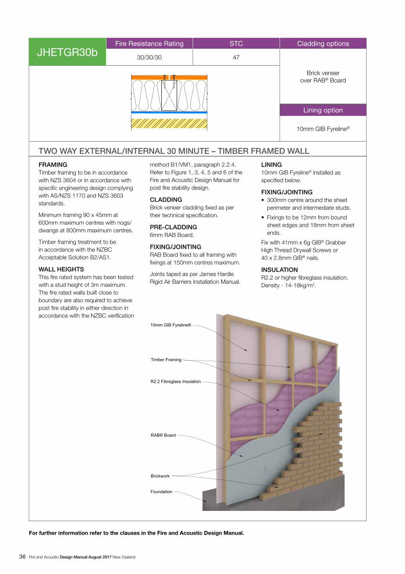
36 Fire and Acoustic Design Manual August 2017 New Zealand
FRAMING Timber framing to be in accordance with NZS 3604 or in accordance with specific engineering design complying with AS/NZS 1170 and NZS 3603 standards.
Minimum framing 90 x 45mm at 600mm maximum centres with nogs/dwangs at 800mm maximum centres.
Timber framing treatment to be in accordance with the NZBC Acceptable Solution B2/AS1.
WALL HEIGHTSThis fire rated system has been tested with a stud height of 3m maximum. The fire rated walls built close to boundary are also required to achieve post fire stability in either direction in accordance with the NZBC verification
method B1/VM1, paragraph 2.2.4. Refer to Figure 1, 3, 4, 5 and 6 of the Fire and Acoustic Design Manual for post fire stability design.
CLADDING Brick veneer cladding fixed as per their technical specification.
PRE-CLADDING6mm RAB Board.
FIXING/JOINTINGRAB Board fixed to all framing with fixings at 150mm centres maximum.
Joints taped as per James Hardie Rigid Air Barriers Installation Manual.
LINING10mm GIB Fyreline® installed as specified below.
FIXING/JOINTING• 300mm centre around the sheet
perimeter and intermediate studs.
• Fixings to be 12mm from bound sheet edges and 18mm from sheet ends.
Fix with 41mm x 6g GIB® Grabber High Thread Drywall Screws or 40 x 2.8mm GIB® nails.
INSULATIONR2.2 or higher fibreglass insulation. Density - 14-18kg/m3.
For further information refer to the clauses in the Fire and Acoustic Design Manual.
TWO WAY EXTERNAL/INTERNAL 30 MINUTE – TIMBER FRAMED WALL
JHETGR30bFire Resistance Rating STC Cladding options
30/30/30 47
Brick veneer over RAB® Board
Lining option
10mm GIB Fyreline®
10mm GIB Fyreline®
Timber Framing
R2.2 Fibreglass Insulation
Brickwork
Foundation
RAB® Board
jh04 jhetgr30_cld_bat_ren.dwg

Fire and Acoustic Design Manual August 2017 New Zealand 37
10 Internal floors/ceilings
The IIC ratings for the following systems have been calculated without any floor covering over the Secura Interior Flooring.
The products specified in these systems must be installed in accordance with their manufacturer’s specifications.
Secura Interior Flooring used as flooring over the floor joists is suitable to achieve fire and acoustic rated floors. The floor joists must comply with NZS 3604 span tables or the specific engineering design. Refer to Secura Interior Flooring Installation Manual for installing Secura Interior Flooring.
Floor coverings have a significant contribution in enhancing the IIC rating of floor / ceiling system e.g. a floor having carpet covering will provide a lot better IIC rating when compared to ceramic tiles.

38 Fire and Acoustic Design Manual August 2017 New Zealand
JHFTGS30
Fire Resistance Rating STC / IIC Floor/Lining option
30 46/33
Secura™ Interior Flooring with 13mm GIB Fyreline®
FRAMING Floor joists to be in accordance with NZS 3604 or alternatively, solid timber joist, Hyspan® and Hyjoist® series joists can also be used in accordance with a specific engineering design meeting the requirements of AS/NZS 1170.
Minimum joist framing 200 x 50mm at 450mm maximum centres with solid strutting at 1800mm maximum centres.
Timber framing treatment to be in accordance with the NZBC Acceptable Solution B2/AS1.
Note: Posi-Strut® floor joists are not suitable for this system.
FLOORINGSecura Interior Flooring 19mm.
FIXING/JOINTINGSecura Interior Flooring fixed as per installation manual. Edges other than tongue and groove must be supported over floor joists.
LINING13mm GIB Fyreline® installed as specified below.
FIXING/JOINTING• 200mm centre around the sheet perimeter and
intermediate joists.
• Fixings to be 12mm from bound sheet edges and 18mm from sheet ends.
Fix with 25mm x 6g GIB® Grabber® Drywall Self Tapping Screws.
For further information refer to the clauses in the Fire and Acoustic Design Manual.
TWO WAY 60 MINUTE – TIMBER FRAMED FLOOR

Fire and Acoustic Design Manual August 2017 New Zealand 39
JHFTGS60
Fire Resistance Rating STC / IIC Floor/Lining option
60 47/37
Secura™ Interior Flooring with 16mm GIB Fyreline®
FRAMING Floor joists to be in accordance with NZS 3604 or alternatively, solid timber joist, Hyspan® and Hyjoist® series joists can also be used in accordance with a specific engineering design meeting the requirements of AS/NZS 1170.
Minimum joist framing 200 x 50mm at 450mm maximum centres with solid strutting at 1800mm maximum centres.
Timber framing treatment to be in accordance with the NZBC Acceptable Solution B2/AS1.
Note: Posi-Strut® floor joists are not suitable for this system.
FLOORINGSecura Interior Flooring 19mm.
FIXING/JOINTINGSecura Interior Flooring fixed as per installation manual. Edges other than tongue and groove must be supported over floor joists.
LINING16mm GIB Fyreline® installed as specified below.
FIXING/JOINTING• 200mm centre around the sheet perimeter and
intermediate joists.
• Fixings to be 12mm from bound sheet edges and 18mm from sheet ends.
Fix with 25mm x 6g GIB® Grabber® Drywall Self Tapping Screws.
For further information refer to the clauses in the Fire and Acoustic Design Manual.
TWO WAY 60 MINUTE – TIMBER FRAMED FLOOR

40 Fire and Acoustic Design Manual August 2017 New Zealand
JHFTGSd60
Fire Resistance Rating STC / IIC Floor/Lining option
60 67/57
Secura™ Interior Flooring with 2 x 13mm GIB Fyreline®
Additional layer of Secura™ Interior Flooring to James
Hardie Acoustic Floor Channel and James Hardie Acoustic Cradle
FRAMING Floor joists to be in accordance with NZS 3604 or alternatively, solid timber joist, Hyspan® and Hyjoist® series joists can also be used in accordance with a specific engineering design meeting the requirements of AS/NZS 1170.
Floor joist depth to be 200mm minimum provide at 450mm c/c maximum spacing.
Solid blocking for floor/ceiling to wall junctions to be in accordance with NZS 3604 or as per floor joist manufacturer.
Nogs/framing is required at the perimeter of fire rated ceiling to facilitate GIB Fyreline® fixing.
Timber framing treatment to be in accordance with the NZBC Acceptable Solution B2/AS1.
Note: Posi-Strut® floor joists are not suitable for this system.
FLOORSecura Interior Flooring 2700 x 600 x 19mm.
FIXING/JOINTINGSecura Interior Flooring fixed as per its installation manual. Flooring edges other than tongue and groove must be supported over floor joists.
INSULATIONAcoustic insulation between timber joists. Minimum 9.6kg/m3.
FLOATING FLOORSecura Interior Flooring 2700 x 600 x 19mm fixed to James Hardie Acoustic Floor Channel spacing at 450mm maximum centres. Flooring edges other than tongue and groove must be supported over floor channel. Floating Secura Flooring to butt into external/internal walls allowing a gap of 5-8mm. Fill the gap with flexible acoustic sealant.
RUBBER CRADLEJames Hardie Acoustic Rubber Cradle spaced at 450mm maximum centres along the batten.
INSULATIONAcoustic insulation between acoustic floor channel. Minimum 9.6kg/m3.
CEILING LINING2 x 13mm GIB Fyreline® installed at right angles as specified below to the underside of GIB Quiet Clip® and GIB® Rondo® Metal Ceiling Battens.
FIXING• Secura Interior Flooring to be fixed
with self tapping steel screws at 200mm centre around the sheet perimeter and intermediate joists/battens.
• Flooring Fixings to be 12mm from sheet ends and 25mm from t&g sheet joints.
INNER LAYER• 13mm GIB Fyreline® fixed with
25mm x 6g GIB® Grabber® Drywall Self Tapping Screws.
OUTER LAYER
• Fixed with 41mm x 6g screws
• Fyreline® Fixings to be 12mm from board sheet edges and 18mm from sheet end.
• Refer to GIB Fire & Noise system manual for further information.
For further information refer to the clauses in the Fire and Acoustic Design Manual.
TWO WAY 60 MINUTE – TIMBER FRAMED FLOOR
Secura™ Interior Flooring
Secura™ Interior Flooring
James Hardie Acoustic Floor Channel over James Hardie Acoustic Cradle
Acoustic Insulation
Acoustic Insulation
2 x 13mm GIB Fyreline®
GIB® Rondo® Metal Ceiling Batten & Quiet Clip®
Timber floor joist/Hyspan®/Hyjoist

Fire and Acoustic Design Manual August 2017 New Zealand 41
Study the James Hardie fixing manual for the cladding or lining system to be used. Obtain the FRR or acoustic system specification required on your project. This should provide you with a specification number which clearly indicates the FRR performance required to be achieved. Additionally, the cladding or lining thickness required to obtain the desired sound attenuation should also be clearly specified. The specification corresponding to the number, FRR and framing specified can be quickly located using the system index in section 4 of this manual. Study section 8 and 9 to ensure the basic requirements for the system specified. Those basic requirements together with the following details will give you sufficient information to ensure the system you construct will provide the desired fire and acoustic performance.
Additional construction details (eg. Intertenancy T junctions etc) are available for download at www.jameshardie.co.nz
11.1 FRAMINGThe framing must be erected as per the requirements of this specification. If any alterations are made to the timber frame set-out, ensure that the designer is informed. Set-out joints and control joints are planned as per the relevant James Hardie technical specification.
• �Timber framing must either be fixed as per NZS 3604 or SED specifications.
• Check erected frame for straightness. To achieve the desired aesthetic results it must be in accordance with NZS 3604.
• Minimum timber stud size required is 90 x 45mm.
Note: Accuracy of nogs / dwangs spacing at 800mm is important to ensure the tight fit of the insulation.
11.2 RAB BOARD / FLEXIBLE UNDERLAYAll external James Hardie claddings must have RAB Board or flexible underlay installed beneath it. Refer to project specifications and this manual for more details. Installation of flexible underlay or RAB Board must be as per the manufacturer’s recommendations and this manual.
11.3 INSULATIONFIBREGLASS INSULATIONFit the specified insulation tightly in all framing cavities against the flexible underlay. Always ensure that the flexible underlay is not pushed out of the framing plane as it will tend to block off the cavity drainage where the cladding is fixed over cavity battens.
JAMES HARDIE MINERAL INSULATIONIf you are not familiar with James Hardie Mineral Insulation then you must read section 14.1 on safe working practices, storage and handling of this product.
The pre-cut sizes are 50mm bigger in length and width than the cavity size to ensure a tight friction fit in the cavity.
If the cavity to be insulated is smaller than the size of insulation supplied, the insulation may be cut to fit to size. Ensure that insulation is at least 50mm bigger in each direction than the size of frame cavity to be filled so that a tight friction fit is achieved.
11 Construction details
11.4 JAMES HARDIE CLADDING OR LINING
Use any standard jointing details as described in the appropriate James Hardie technical specifications. Note that expressed joints cannot exceed a maximum of 10mm in width vertically or horizontally.
The expressed jointing system followed doesn’t affect the fire ratings in timber frame construction but this jointing option must not be used with steel frame construction.
11.5 CAVITY CONSTRUCTIONThe fire ratings are not affected when the James Hardie cladding or any other non-combustible cladding is fixed using a timber cavity batten (18-25mm) construction method. Follow the cavity construction specification developed for each cladding materials supplied by James Hardie or their manufacturer.
The fire rated performance of James Hardie claddings fixed over a timber cavity batten (18-25mm) has been assessed by BRANZ (Reference FSR562).
A horizontal separation within the cavity must be provided at the floor levels where there are two separate tenancies one above the other. Refer to Figure 7.
Titan Facade Panel, Stria Cladding, EasyLap Panel and Axon Panel when fixed to CLD Structural Cavity Batten must be installed over RAB Board to achieve the fire rating. Refer to RAB Board fire rated systems.
11.6 GIB® STANDARD PLASTERBOARD AND GIB FYRELINE® LINING
GIB® Standard plasterboard and GIB Fyreline® linings where specified in the system must be installed as per Winstone Wallboards technical literature. Also refer to Clause 5.11.
11.7 SERVICES PENETRATIONSDue to the complexities involved with fire performance of various materials and assemblies, it is suggested to explore all options that may help in avoiding the penetrations through fire rated walls.
A penetration through a fire rated wall must be carefully detailed and constructed in accordance with the information fire sleeve/collar supplier. A penetration must at least be 100mm from the sheet/panel edges.
Any gaps around penetrations or joints etc. must be sealed with tested intumescent sealers.
The pipe up to 20mm diameter can run vertically along side a stud within the wall framing. Insulation must be tightly fitted around these pipes. Ask James Hardie at 0800 808 868 for further assistance in this matter.
Refer to proprietary fire sealant or accessories suppliers for further information about the correct use of their product.

42 Fire and Acoustic Design Manual August 2017 New Zealand
12 Construction details
12.1 JAMES HARDIE FIRE RATED BOUNDARY WALL AND SOFFITS CONSTRUCTION
Figure 1 will provide FRR Soffits which should be used in conjunction with James Hardie FRR exterior systems. The FRR soffit system has been assessed by BRANZ under FAR2597.
Table 1
Description Page
Figure 1: Boundary Wall Bottom Plate Fixing – Concrete Foundation 43
Figure 2: Boundary Wall Bottom Plate Fixing – Concrete Foundation 44
Figure 3: Boundary Wall Bottom Plate Fixing – Blockwall Foundation 45
Figure 4: Boundary Wall Bottom Plate Fixing – Blockwall Foundation 46
Figure 5: Boundary Wall Bottom Plate – Timber Foundation Parallel 47
Figure 6: Boundary Wall Bottom Plate – Timber Foundation Right Angle 48
Figure 7: Intertenancy Vertical Fire Separation 49
Figure 8: Lining/Cladding Fixing and Layout to Boundary Wall 50
Figure 9: Weatherboard Fixing and Layout to Boundary Wall 51
Figure 10: Concrete Slab to Timber Intertenancy Wall Junction 52
Figure 11: Timber Floor to Floor Intertenancy Wall Junction 53
Figure 12: Split Level Floor to Intertenancy Wall Junction 54
Figure 13: Floor to Deck junction 55
Figure 14: Sub Floor FRR Partition Wall 56
Figure 15: Intertenancy Wall to External Wall Junction with Cavity 57
Figure 16: Intertenancy Wall to External Wall Junction without Cavity 57
Figure 17: Intertenancy Timber Wall to Concrete 58
Figure 18: Linea Weatherboard Intertenancy Wing Wall Junction 59
Figure 19: Intertenancy Wall to Roof Junction 60
Figure 20: Parapet Wall to Roof Junction 61

Fire and Acoustic Design Manual August 2017 New Zealand 43
Figure 1: Boundary Wall Bottom Plate Fixing - Concrete Foundation

44 Fire and Acoustic Design Manual August 2017 New Zealand
Figure 2: Boundary Wall Bottom Plate Fixing - Concrete Foundation

Fire and Acoustic Design Manual August 2017 New Zealand 45
Figure 3: Boundary Wall Bottom Plate Fixing – Blockwall Foundation

46 Fire and Acoustic Design Manual August 2017 New Zealand
Figure 4: Boundary Wall Bottom Plate Fixing – Blockwall Foundation

Fire and Acoustic Design Manual August 2017 New Zealand 47
Figure 5: Boundary Wall Bottom Plate - Timber Foundation Parallel

48 Fire and Acoustic Design Manual August 2017 New Zealand
Figure 6: Boundary Wall Bottom Plate - Timber Foundation Right Angle

Fire and Acoustic Design Manual August 2017 New Zealand 49
Figure 7: Intertenancy Vertical Fire Separation

50 Fire and Acoustic Design Manual August 2017 New Zealand
Figure 8: Lining/Cladding Fixing and Layout to Boundary Wall

Fire and Acoustic Design Manual August 2017 New Zealand 51
Figure 9: Weatherboard Fixing and Layout to Boundary Wall
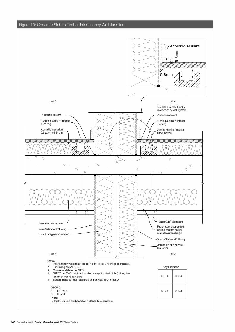
52 Fire and Acoustic Design Manual August 2017 New Zealand
Figure 10: Concrete Slab to Timber Intertenancy Wall Junction

Fire and Acoustic Design Manual August 2017 New Zealand 53
Figure 11: Timber Floor to Floor Intertenancy Wall Junction

54 Fire and Acoustic Design Manual August 2017 New Zealand
Figure 12: Split Level Floor to Intertenancy Wall Junction

Fire and Acoustic Design Manual August 2017 New Zealand 55
Figure 13: Floor to Deck Junction

56 Fire and Acoustic Design Manual August 2017 New Zealand
Figure 14: Sub Floor FRR Partition Wall

Fire and Acoustic Design Manual August 2017 New Zealand 57
Figure 15: Intertenancy Wall to External Wall Junction with Cavity
Figure 16: Intertenancy Wall to External Wall Junction without Cavity

58 Fire and Acoustic Design Manual August 2017 New Zealand
Figure 17: Intertenancy Timber Wall to Concrete

Fire and Acoustic Design Manual August 2017 New Zealand 59
Figure 18: Linea Weatherboard Intertenancy Wing Wall Junction

60 Fire and Acoustic Design Manual August 2017 New Zealand
Figure 19: Intertenancy Wall to Roof Junction

Fire and Acoustic Design Manual August 2017 New Zealand 61
Figure 20: Parapet Wall to Roof Junction

62 Fire and Acoustic Design Manual August 2017 New Zealand
13 Safe working practice
STAY HEALTHY WHEN WORKING WITH BUILDING PRODUCTS CONTAINING CRYSTALINE SILICA
CRYSTALLINE SILICA What is it? Why and when is it a health hazard?
CRYSTALLINE SILICA IS • Commonly known as sand or quartz
• Found in many building products e.g. concrete, bricks, grout, wallboard, ceramic tiles, and all fibre cement materials
WHY IS CRYSTALLINE SILICA A HEALTH HAZARD? • Silica can be breathed deep into the lungs when present in the
air as a very fine (respirable) dust
• Exposure to silica dust without taking the appropriate safety measures to minimise the amount being breathed in, can lead to a potentially fatal lung disease – silicosis – and has also been linked with other diseases including cancer. Some studies suggest that smoking may increase these risks.
• The most hazardous dust is the dust you cannot see!
WHEN IS CRYSTALLINE SILICA A HEALTH HAZARD?• It’s dangerous to health if safety protocols to control dust
are not followed when cutting, drilling or rebating a product containing crystalline silica.
• Products containing silica are harmless if intact (e.g. an un-cut sheet of wall board).
FAILURE TO ADHERE TO OUR WARNINGS, SAFETY DATA SHEETS AND INSTALLATION INSTRUCTIONS WHEN WORKING WITH JAMES HARDIE PRODUCTS MAY LEAD TO SERIOUS PERSONAL INJURY OR DEATH.
AVOID BREATHING IN CRYSTALLINE SILICA DUST!
SAFE WORKING PRACTICES NEVER use a power saw indoors or in a poorly ventilated
area
NEVER dry sweep
ALWAYS use M Class extractor unit as a minimum and always hose down with water/wet wipe for clean up
NEVER use grinders
ALWAYS use a circular sawblade specifically designed to minimise dust creation when cutting fibre cement – preferably a sawblade that carries the HardieBlade™ logo or one with at least equivalent performance.
ALWAYS follow tool manufacturers’ safety recommendations
ALWAYS expose only the minimum required depth of blade for the thickness of fibre cement to be cut
ALWAYS wear an approved properly-fitted, approved dust mask (P1 or P2) or respirator
Use one of the following methods based on the required cutting rate:
BEST
• HardieKnife™
• Hand guillotine
• Fibreshear
BETTER
• Dust reducing circular saw equipped with HardieBlade™ Saw Blade and M Class extractor unit.
GOOD
• Dust reducing circular saw with HardieBlade™ Saw Blade
WORKING OUTDOORS Make sure you work in a well ventilated area
Position cutting station so wind will blow dust away from yourself and others in the working area
Cut products with either a HardieKnife or fibre cement shears or, when not feasible, use a HardieBlade™ Saw Blade (or equivalent) and a dust-reducing circular saw attached to a M Class extractor unit
When sawing, sanding, rebating, drilling or machining fibre cement products, always:
- Wear your P1 or P2 mask (correctly fitted in accordance with manufacturers’ instructions) and when others are close by, ask them to do the same
- If you are not clean shaven, then use a powered air respirator with a loose fitting head top.
- Wear safety glasses
- Wear hearing protection
- When others are close by, ask them to do the same.
WORKING INDOORS Never cut using a circular saw indoors
Position cutting station in a well ventilated area
Cut ONLY using a HardieKnife, hand guillotine or fibreshears (manual, electric or pneumatic)
Make sure you clean up BUT never dry sweep. Always hose down with water/wet wipe or use an M Class extractor unit
IF CONCERN STILL EXISTS ABOUT EXPOSURE LEVELS OR YOU DO NOT COMPLY WITH THE ABOVE PRACTICES, YOU SHOULD ALWAYS CONSULT A QUALIFIED INDUSTRIAL HYGIENIST.

Fire and Acoustic Design Manual August 2017 New Zealand 63
WORKING INSTRUCTIONS• Refer to Recommended Safe Working
Practices before starting any cutting or machining of product.
HARDIEBLADE™ SAW BLADEThe HardieBlade™ Saw Blade used with a dust-reducing saw is ideal for fast, clean cutting of James Hardie fibre cement products. A dust-reducing saw uses a dust deflector or a dust collector connected to a vacuum system. When sawing, clamp a straight-edge to the sheet as a guide and run the saw base plate along the straight edge when making the cut.
HOLE-FORMINGFor smooth clean cut circular holes:
• Mark the centre of the hole on the sheet.
• Pre-drill a ‘pilot’ hole.
• Using the pilot hole as a guide, cut the hole to the appropriate diameter with a hole saw fitted to a heavy duty electric drill.
For irregular holes:
• Small rectangular or circular holes can be cut by drilling a series of small holes around the perimeter of the hole then tapping out the waste piece from the sheet face.
• Tap carefully to avoid damage to sheets, ensuring that the sheet edges are properly supported.
STORAGE & DELIVERY
KEEPING PRODUCTS AND PEOPLE SAFEOFF LOADING
James Hardie products should be off-loaded carefully by hand or by forklift.
James Hardie products should not be rolled or dumped off a truck during the delivery to the jobsite.
STORAGE James Hardie products should be stored:
in their original packaging
under cover where possible or otherwise protected with a waterproof covering to keep products dry
off the ground – either on a pallet or adequately supported on timber or other spacers
flat so as to minimise bending
James Hardie products must not be stored:
directly on the ground
in the open air exposed to the elements
JAMES HARDIE IS NOT RESPONSIBLE FOR DAMAGE DUE TO IMPROPER STORAGE AND HANDLING.
TIPS FOR SAFE AND EASY HANDLING
WEATHERBOARD PRODUCTS Do not lift planked products flat and in the middle
Carry the products on the edge
If only one person is carrying the product, hold it in the middle and spread arms apart to better support the product
If two people are carrying the plank, hold it near each end and on edge
Exercise care when handling weatherboard products to avoid damaging the edges/corners
SHEET PRODUCTS Carry with two people
Hold near each end and on edge
Exercise care when handling sheet products to avoid damaging the edges/corners

64 Fire and Acoustic Design Manual August 2017 New Zealand
14 Product information and accessories
Table 2
Accessories/tools supplied by James Hardie
Accessories Description Quantity/size (approx)
James Hardie Mineral Insulation 600 x 800 x 90 mm – 2.4m2 per bale Code: 304904
James Hardie Acoustic Floor Channel
40 x 42 x 1800mm Code: 305922
James Hardie Acoustic Cradle Code: 305920
James Hardie Flooring Shims Code: 305925
Claddings or linings as per the relevant James Hardie product literature

Fire and Acoustic Design Manual August 2017 New Zealand 65
Table 3
Accessories/tools not supplied by James Hardie
James Hardie recommends the following products for use in conjunction with James Hardie products. James Hardie does not supply these products and does not provide a warranty for their use. Please contact component manufacturer for information on their warranties and further information on their products.
Accessories DescriptionFlexible underlayMust comply with E2/AS1 requirements.
HardieFlex™ Nail galvanised or stainless steel.
Flexible tapeA flexible self-adhesive tape used in preparation of a window. e.g. Marshall Innovations, Tyvek®, Flexwrap™, etc.
Finishing NailerGas or pneumatic finishing nailer for fixing
PEF RodUsed to form an air seal between the window liner and window opening frame.
Inseal Strip 3109 Used for sealing around window jambs.
Head Flashing compliant with E2Material must comply with E2/AS1 requirements.
SealantFire retardant / acoustic sealant to seal the joints. Refer to sealant manufacturer’s recommendations before applying. e.g. GIB Soundseal®, Bostik Acoustic Sealant, Holdfast Gorilla Firestop MS Sealant, FirePro Centabuild M755 Acoustic Sealant.Thermal Fire BattensThe battens are made by cutting a 100mm wide strip from 9mm thick Monotek Sheet and adhering a 10mm thick XPS (Extruded Polystyrene) to the strip.
GIB Fyreline®
GIB® Standard Plasterboard
GIB Quiet Tie®
GIB Quiet Clip®
FRR Penetrations
Marshall Innovations, Tyvek®, Flexwrap™ are trademarks registered to their owners

66 Fire and Acoustic Design Manual August 2017 New Zealand
Notes

August 2017
For full product specific warranties, please refer to the relevant product technical specification or installation manual. They are also available for download at www.jameshardie.co.nz or simply Ask James Hardie on 0800 808 868.
Fire andAcousticProduct Warranty
Ask James HardieTM I Call 0800 808 868 I jameshardie.co.nz

Ask James HardieTM I Call 0800 808 868 I jameshardie.co.nz
Copyright August 2017. © James Hardie New Zealand. TM and ® denotes a Trademark or Registered Mark owned by James Hardie Technology Limited.