STATNAMIC LOAD TESTING Development, Interpretation of Results, Advantages.

Eaton’s B-Line series safety gratings www.eaton.com/b-lineseries 52
Traction
Tread
Gratin
g
Traction Tread Grating - Design Load Table of Contents & Advantages
AdvantagesTraction Tread flooring feature a surface with hundreds of perforated buttons that provide slip-resistance in all directions making it a practical choice for industrial applications.• Appropriate for commercial & industrial applications where
pedestrian traffic is a consideration• Perfectly suited for ADA-compliant requirements• Easily adapted for a multitude of applications, offering a safe
walking-working surface for walkways, ramps, stair treads and equipment platforms
• Ideal for the manufacture of special and fabricated products, and is often used as a reconditioning material over existing surfaces that do not provide slip-resistance
• Sheet size - 36" x 120"• Can be cut to order• Variations of hole patterns are available upon request • Special fabrication, cutting or specialty configurations
available upon request• Material options: see page 53
Traction Tread stair treads Traction Tread planks Traction Tread ladder rungs
Traction Tread™ Design Load TablesSteel, aluminum, stainless steel
Planks - 7" width . . . . . . . . . . . . . . . . . . . . . . . . . . . . . . . . . . . . . . . . . . . . . . 54
Planks - 10" width . . . . . . . . . . . . . . . . . . . . . . . . . . . . . . . . . . . . . . . . . . . . . 55
Planks - 12" width . . . . . . . . . . . . . . . . . . . . . . . . . . . . . . . . . . . . . . . . . . . . . 56
Planks - 10" width, large hole . . . . . . . . . . . . . . . . . . . . . . . . . . . . . 57
Stair treads . . . . . . . . . . . . . . . . . . . . . . . . . . . . . . . . . . . . . . . . . . . . . . . . . . . . . .58
Ladder rungs . . . . . . . . . . . . . . . . . . . . . . . . . . . . . . . . . . . . . . . . . . . . . . . . . . .59

Eaton’s B-Line series safety gratings www.eaton.com/b-lineseries 53
Trac
tio
n T
read
G
rati
ng
Traction Tread Grating -Material Options & Hole Patterns
Material options • Hot rolled, pickled and oiled carbon steel:
11 gauge (5.0 lbs./sq. ft.)
12 gauge (4.3 lbs./sq. ft.)
13 gauge (3.8 lbs./sq. ft.)
14 gauge (3.1 lbs./sq. ft.)
16 gauge (2.5 lbs./sq. ft.)
• Aluminum alloy 5052-H32: .125" (1.6 lbs./sq. ft.)
Sheet size • Standard - 36" x 120"
• Cut to order
Standard pattern
Button detail
3/32"
3/8" Dia. 1/8" Dia. hole
1/8" Radius
• TractionTread™isavailableasshownaboveasastandardproduct.However,variationstothesurfacedesigncanbeproducedaccordingtoyourrequirement(seeexamplesillustratedbelow).
Star pattern Square pattern Rectangular pattern
OEM pattern Drain hole pattern Dimple only pattern

Eaton’s B-Line series safety gratings www.eaton.com/b-lineseries 54
Traction
Tread
Gratin
g
Traction Tread Grating - Safe Loading Tables
Traction Tread Plank — Width 7" Nominal
Allowable loads and deflections: U=Uniform load (lb./ft.2) D=Deflection (in.) Channel Weight Span Material Depth lb./lin. Load/ Gauge in. ft. Catalog Defl. (mm) (kg/m) Number Code 2'-0" 2'-6" 3'-0" 3'-6" 4'-0" 4'-6" 5'-0" 5'-6" 6'-0" 6'-6" 7'-0" 7'-6" 8'-0" 9'-0" 10'-0" 11'-0" 12'-0"
11/2" 3.40 TT71513 GL U 824 675 488 351 257 201 158 144 127 92 69 (38.1) (5.06) D 0.02 0.04 0.06 0.08 0.10 0.13 0.15 0.20 0.25 0.25 0.25 Steel 2" 3.71 TT72013 GL U 1642 1345 973 700 513 400 315 287 253 184 137 104 80 50 13 ga. (50.8) (5.52) D 0.02 0.04 0.06 0.08 0.10 0.13 0.15 0.20 0.25 0.25 0.25 0.25 0.25 0.25 3" 4.11 TT73013 GL* U 4378 3587 2595 1867 1368 1068 841 766 676 491 365 277 214 133 88 60 42 (76.2) (6.11) D 0.02 0.04 0.06 0.08 0.10 0.13 0.15 0.20 0.25 0.25 0.25 0.25 0.25 0.25 0.25 0.25 0.25
11/2" 4.72 TT71511 GL U 1032 845 612 440 323 252 198 180 159 116 86 (38.1) (7.02) D 0.02 0.04 0.06 0.08 0.10 0.13 0.15 0.20 0.25 0.25 0.25 Steel 2" 5.15 TT72011 GL U 2084 1707 1235 889 651 508 400 364 322 233 174 132 102 64 11 ga. (50.8) (7.66) D 0.02 0.04 0.06 0.08 0.10 0.13 0.15 0.20 0.25 0.25 0.25 0.25 0.25 0.25 3" 6.13 TT73011 GL* U 5619 4603 3330 2396 1756 1370 1079 982 867 630 468 355 274 171 112 77 54 (76.2) (9.12) D 0.02 0.04 0.06 0.08 0.10 0.13 0.15 0.20 0.25 0.25 0.25 0.25 0.25 0.25 0.25 0.25 0.25
11/2" 1.63 TT715125 AL* U 359 294 213 153 112 88 69 63 55 40 30 Alum (38.1) (2.42) D 0.02 0.04 0.06 0.08 0.10 0.13 0.15 0.20 0.25 0.25 0.25 0.125" 2" 1.80 TT720125 AL U 727 595 431 310 227 177 139 127 112 81 61 46 35 22 (50.8) (2.68) D 0.02 0.04 0.06 0.08 0.10 0.13 0.15 0.20 0.25 0.25 0.25 0.25 0.25 0.25
Product selection/design tables
13/16"
15/16" 8 @ 5/8" each
11/4"90°
67/8"
Engineering Data For Both Channels
Channel Material Depth Sx Ix Gauge in. in.3 in.4
Steel 11/2" 0.344 0.396 13 ga. 2" 0.534 0.806 3" 1.000 2.196 Steel 11/2" 0.273 0.316 11 ga. 2" 0.420 0.636 3" 1.711 0.782 Aluminum 11/2" 0.348 0.400 .125" 2" 0.540 0.815
Plank lengths• 120" and 144" lengths
Material options• Mill-galvanized steel: 11 gauge and 13 gauge
• Aluminum alloy 5052-H32: .125"
• Also available by special order in hot rolled, pickled and oiled carbon steel: 11 gauge and 13 gauge; consult factory
* Available on special order. Consult factory.

Eaton’s B-Line series safety gratings www.eaton.com/b-lineseries 55
Trac
tio
n T
read
G
rati
ng
Traction Tread Grating - Safe Loading TablesTraction Tread Plank — Width 10" Nominal
Allowable loads and deflections: U=Uniform load (lb./ft.2) D=Deflection (in.) Channel Weight Span Material Depth lb./lin. Load/ Gauge in. ft. Catalog Defl. (mm) (kg/m) Number Code 2'-0" 2'-6" 3'-0" 3'-6" 4'-0" 4'-6" 5'-0" 5'-6" 6'-0" 6'-6" 7'-0" 7'-6" 8'-0" 9'-0" 10'-0" 11'-0" 12'-0"
11/2" 4.32 TT101513 GL U 628 515 372 268 196 153 121 110 97 70 52 (38.1) (6.43) D 0.02 0.04 0.06 0.08 0.10 0.13 0.15 0.20 0.25 0.25 0.25 Steel 2" 4.63 TT102013 GL U 1267 1038 751 540 396 309 243 221 195 142 106 80 62 13 ga. (50.8) (6.89) D 0.02 0.04 0.06 0.08 0.10 0.13 0.15 0.20 0.25 0.25 0.25 0.25 0.25 3" 5.24 TT103013 GL* U 3412 2795 2022 1455 1066 832 655 597 527 382 284 216 167 104 68 47 33 (76.2) (7.80) D 0.02 0.04 0.06 0.08 0.10 0.13 0.15 0.20 0.25 0.25 0.25 0.25 0.25 0.25 0.25 0.25 0.25
11/2" 6.01 TT101511 GL U 787 645 466 336 246 192 151 138 121 88 66 (38.1) (8.94) D 0.02 0.04 0.06 0.08 0.10 0.13 0.15 0.20 0.25 0.25 0.25 Steel 2" 6.44 TT102011 GL U 1605 1315 951 685 502 392 308 281 248 180 134 101 78 11 ga. (50.8) (9.58) D 0.02 0.04 0.06 0.08 0.10 0.13 0.15 0.20 0.25 0.25 0.25 0.25 0.25 3" 7.45 TT103011 GL* U 4380 3588 2595 1868 1369 1068 841 766 676 491 365 277 214 134 88 60 42 (76.2) (11.06) D 0.02 0.04 0.06 0.08 0.10 0.13 0.15 0.20 0.25 0.25 0.25 0.25 0.25 0.25 0.25 0.25 0.25
11/2" 2.07 TT1015125 AL* U 275 225 163 117 86 67 53 48 42 31 23 Alum (38.1) (3.08) D 0.02 0.04 0.06 0.08 0.10 0.13 0.15 0.20 0.25 0.25 0.25 0.125" 2" 2.22 TT1020125 AL U 560 469 332 239 175 137 107 98 86 63 47 35 27 (50.8) (3.30) D 0.02 0.04 0.06 0.08 0.10 0.13 0.15 0.20 0.25 0.25 0.25 0.25 0.25
Product selection/design tables
13/16"
7/8" 13 @ 5/8" each
11/4"90°
97/8"
Engineering Data For Both Channels
Channel Material Depth Sx Ix Gauge in. in.3 in.4
Steel 11/2" 0.344 0.396 13 ga. 2" 0.534 0.806 3" 1.000 2.196 Steel 11/2" 0.273 0.316 11 ga. 2" 0.420 0.636 3" 1.711 0.782 Aluminum 11/2" 0.348 0.400 .125" 2" 0.540 0.815
Plank Lengths:• 120" and 144" lengths
Material Options:• Mill-galvanized steel: 11 gauge and 13 gauge
• Aluminum alloy 5052-H32: .125"
• Also available by special order in hot rolled, pickled and oiled carbon steel: 11 gauge and 13 gauge; consult factory
* Available on special order. Consult factory.
Eaton’s B-Line series safety gratings www.eaton.com/b-lineseries 56
Traction
Tread
Gratin
g
Traction Tread Grating - Safe Loading TableTraction Tread Plank — Width 12" Nominal
Allowable loads and deflections: U=Uniform load (lb./ft.2) D=Deflection (in.) Channel Weight Span Material Depth lb./lin. Load/ Gauge in. ft. Catalog Defl. (mm) (kg/m) Number Code 2'-0" 2'-6" 3'-0" 3'-6" 4'-0" 4'-6" 5'-0" 5'-6" 6'-0" 6'-6" 7'-0" 7'-6" 8'-0" 9'-0" 10'-0" 11'-0" 12'-0"
11/2" 4.93 TT121513 GL U 544 445 322 232 170 133 104 95 84 61 45 (38.1) (7.33) D 0.02 0.04 0.06 0.08 0.10 0.13 0.15 0.20 0.25 0.25 0.25 Steel 2" 5.24 TT122013 GL U 1101 902 652 469 344 268 211 192 170 123 92 70 54 13 ga. (50.8) (7.80) D 0.02 0.04 0.06 0.08 0.10 0.13 0.15 0.20 0.25 0.25 0.25 0.25 0.25 3" 5.57 TT123013 GL* U 2986 2446 1769 1273 933 728 573 522 461 335 249 189 146 91 60 41 29 (76.2) (8.29) D 0.02 0.04 0.06 0.08 0.10 0.13 0.15 0.20 0.25 0.25 0.25 0.25 0.25 0.25 0.25 0.25 0.25
11/2" 6.90 TT121511 GL U 682 559 404 291 213 166 131 119 105 76 57 (38.1) (10.27) D 0.02 0.04 0.06 0.08 0.10 0.13 0.15 0.20 0.25 0.25 0.25 Steel 2" 7.30 TT122011 GL U 1395 1143 827 595 436 340 268 244 215 156 116 88 68 11 ga. (50.8) (10.86) D 0.02 0.04 0.06 0.08 0.10 0.13 0.15 0.20 0.25 0.25 0.25 0.25 0.25 3" 8.23 TT123011 GL* U 3831 3138 2270 1634 1197 934 736 670 591 429 319 242 187 117 77 52 37 (76.2) (12.25) D 0.02 0.04 0.06 0.08 0.10 0.13 0.15 0.20 0.25 0.25 0.25 0.25 0.25 0.25 0.25 0.25 0.25
11/2" 2.37 TT1215125 AL U 238 195 141 101 74 58 46 42 37 27 20 Alum (38.1) (3.52) D 0.02 0.04 0.06 0.08 0.10 0.13 0.15 0.20 0.25 0.25 0.25 0.125" 2" 2.52 TT1220125 AL* U 487 399 288 207 152 119 93 85 75 55 41 31 24 (50.8) (3.75) D 0.02 0.04 0.06 0.08 0.10 0.13 0.15 0.20 0.25 0.25 0.25 0.25 0.25
Product selection/design tables
13/16"
15/16" 16 @ 5/8" each
11/4"90°
117/8"
Engineering data For both channels
Channel Material Depth Sx Ix Gauge in. in.3 in.4
Steel 11/2" 0.344 0.396 13 ga. 2" 0.534 0.806 3" 1.000 2.196 Steel 11/2" 0.273 0.316 11 ga. 2" 0.420 0.636 3" 1.711 0.782 Aluminum 11/2" 0.348 0.400 .125" 2" 0.540 0.815
Plank Lengths:• 120" and 144" lengths
Material Options:• Mill-galvanized steel: 11 gauge and 13 gauge
• Aluminum alloy 5052-H32: .125"
• Also available by special order in hot rolled, pickled and oiled carbon steel: 11 gauge and 13 gauge; consult factory
* Available on special order. Consult factory.
Eaton’s B-Line series safety gratings www.eaton.com/b-lineseries 57
Trac
tio
n T
read
G
rati
ng
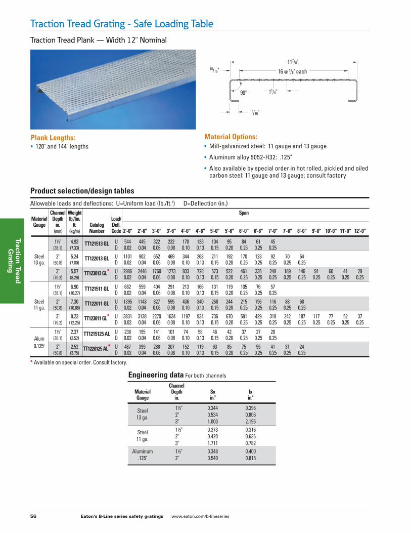
Traction Tread Plank (Large Hole) — Width 10"
Traction Tread Grating - Safe Loading Table
97/8"
Allowable loads and deflections: U=Uniform load (lb./ft.2) D=Deflection (in.) Channel Weight Span Material Depth lb./lin. Load/ Gauge in. ft. Catalog Defl. (mm) (kg/m) Number Code 2'-0" 2'-6" 3'-0" 3'-6" 4'-0" 4'-6" 5'-0" 5'-6" 6'-0" 6'-6" 7'-0" 7'-6" 8'-0" 9'-0" 10'-0"
11/2" 4.28 TT101513LH GL U 621 508 368 265 194 151 119 109 96 70 52 Steel (38.1) (6.37) D 0.02 0.04 0.06 0.08 0.10 0.13 0.15 0.20 0.25 0.25 0.25 13 ga. 2" 4.60 TT102013LH GL U 1251 1025 741 533 391 305 240 219 193 140 104 79 61 (50.8) (6.84) D 0.02 0.04 0.06 0.08 0.10 0.13 0.15 0.20 0.25 0.25 0.25 0.25 0.25
11/2" 5.95 TT101511LH GL U 777 637 461 331 243 190 149 136 120 87 65 Steel (38.1) (8.85) D 0.02 0.04 0.06 0.08 0.10 0.13 0.15 0.20 0.25 0.25 0.25 11 ga. 2" 6.37 TT102011LH GL U 1585 1299 939 676 495 387 304 277 245 178 132 100 77 (50.8) (9.48) D 0.02 0.04 0.06 0.08 0.10 0.13 0.15 0.20 0.25 0.25 0.25 0.25 0.25
11/2" 2.05 TT1015125LH AL U 271 222 161 116 85 66 52 47 42 30 23 Alum (38.1) (3.05) D 0.02 0.04 0.06 0.08 0.10 0.13 0.15 0.20 0.25 0.25 0.25 0.125" 2" 2.20 TT1020125LH AL U 553 453 328 236 173 135 106 97 85 62 46 35 27 (50.8) (3.27) D 0.02 0.04 0.06 0.08 0.10 0.13 0.15 0.20 0.25 0.25 0.25 0.25 0.25
Product selection/design tables
Plank Dimensions:• 120" and 144" lengths
• 11/2" minimum or 2" channel height
• 3⁄8" hole diameter
• Not available in sheets
Material Options:• Mill-galvanized steel: 11 gauge and 13 gauge
• Aluminum alloy 5052-H32: .125"
• Also available by special order in hot rolled, pickled and oiled carbon steel: 11 gauge and 13 gauge; consult factory
• LH (large hole) pattern
13/16"
90°
Engineering data For both channels
Channel Material Depth Sx Ix Gauge in. in.3 in.4
Steel 11/2" 0.344 0.396 13 ga. 2" 0.534 0.806
Steel 11/2" 0.273 0.316 11 ga. 2" 0.420 0.636
Aluminum 11/2" 0.348 0.400 .125" 2" 0.540 0.815

Eaton’s B-Line series safety gratings www.eaton.com/b-lineseries 58
Traction
Tread
Gratin
g
Stair treads
Traction Tread Grating - Safe Loading Table
Safe allowable design loads shown are concentrated at center of span on simple beam.(1) For stair treads, intermediate stringer is recommended for spans over 4 feet.
C = Safe allowable concentrated load of center span on simple beam (lbs.) D=Deflection (in.) Channel Weight Span Material Depth Load/ Gauge lb./lin. Catalog Defl. in. (mm) ft. (kg/m) Number Code 2'-0" 2'-6" 3'-0" 3'-6" 4'-0"(1)
7" Width Steel 11/2" (38.1) 3.73 (5.55) T-TT71513 GL C 555 483 420 352 295 13 ga. 2" (50.8) 4.06 (6.04) T-TT72013 GL C 1107 963 836 702 588
Steel 11/2" (38.1) 4.87 (7.25) T-TT71511 GL C 696 605 526 441 370 11 ga. 2" (50.8) 5.43 (8/08) T-TT72011 GL C 1405 1222 1061 891 746
Alum 11/2" (38.1) 1.70 (2.53) T-TT715125 AL C 242 211 183 154 129 .125 2" (50.8) 1.87 (2.78) T-TT720125 AL C 490 426 370 311 260
10" Width Steel 11/2" (38.1) 4.61 (7.16) T-TT101513 GL C 608 530 460 386 323 13 ga. 2" (50.8) 4.89 (7.28) T-TT102013 GL C 1226 1067 927 778 651
Steel 11/2" (38.1) 6.24 (9.28) T-TT101511 GL C 762 663 576 483 405 11 ga. 2" (50.8) 6.70 (9.97) T-TT102011 GL C 1554 1353 1174 986 826
Alum 11/2" (38.1) 2.11 (3.14) T-TT1015125 AL C 266 232 201 169 141 .125 2" (50.8) 2.35 (3.50) T-TT1020125 AL C 542 472 409 344 288
12" Width Steel 11/2" (38.1) 5.00 (7.44) T-TT121513 GL C 633 551 478 402 336 13 ga. 2" (50.8) 5.70 (8.48) T-TT122013 GL C 1281 1115 968 813 681
Steel 11/2" (38.1) 7.16 (10.65) T-TT121511 GL C 794 691 600 504 422 11 ga. 2" (50.8) 7.58 (11.28) T-TT122011 GL C 1624 1414 1227 1031 863
Alum 11/2" (38.1) 2.45 (3.64) T-TT1215125 AL C 277 241 209 176 147 .125 2" (50.8) 2.60 (3.87) T-TT1220125 AL C 566 493 428 359 301
Deflection (same for all widths and depths) D 0.02 0.04 0.06 0.08 0.10
Product selection/design tables
Carrier plates Carrier plates allow you to create your own custom stair treads. They are sold by the pair. (2 plates = one pair).
Product Width “A” “B” “C” “D”
615⁄16" 11/2" 3/4" 4" 7" (176mm) (38mm) (19mm) (102mm)
(178mm) 615⁄16" 2" 1" 4"
(176mm) (51mm) (25mm) (102mm)
915⁄16" 11/2" 3/4" 7" 10" (252mm) (38mm) (19mm) (178mm)
(254mm) 915⁄16" 2" 1" 7"
(252mm) (51mm) (25mm) (178mm)
1115⁄16" 11/2" 3/4" 9" 12" (303mm) (38mm) (19mm) (227mm)
(305mm) 1115⁄16" 2" 1" 9"
(303mm) (51mm) (25mm) (227mm)
Carrier plate
7/16" x 13/4" Slot 7/16" Dia. Hole
“A”
“B”
“C”
“D”
All treads have welded ends for attachment to stringers.
• Mill-galvanized steel: 11 gauge and 13 gauge
• Aluminum alloy 5052-H32: .125"
• Also available in Hot rolled, pickled and oiled carbon steel: 11 gauge and 13 gauge
• 24" to 48" lengths
• Custom lengths can be made with the use of carrier plates
• 7" 10" and 12" (nominal) widths
• 11/2" and 2" channel heights
Eaton’s B-Line series safety gratings www.eaton.com/b-lineseries 59
Trac
tio
n T
read
G
rati
ng
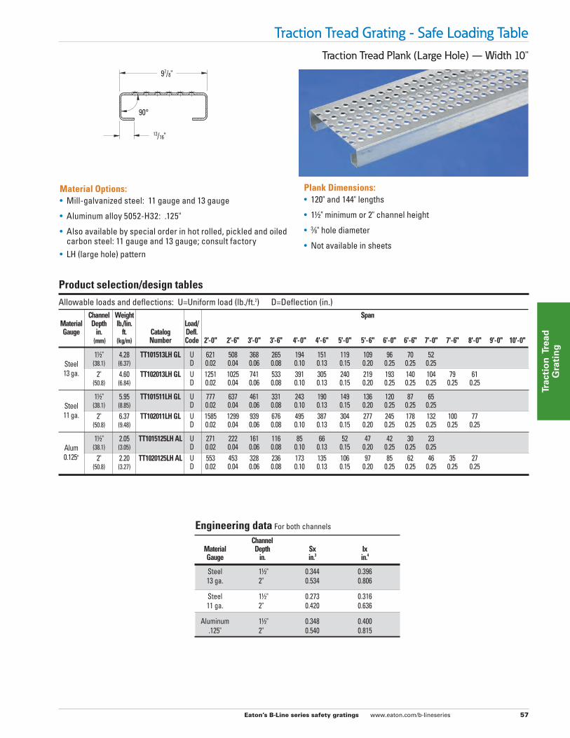
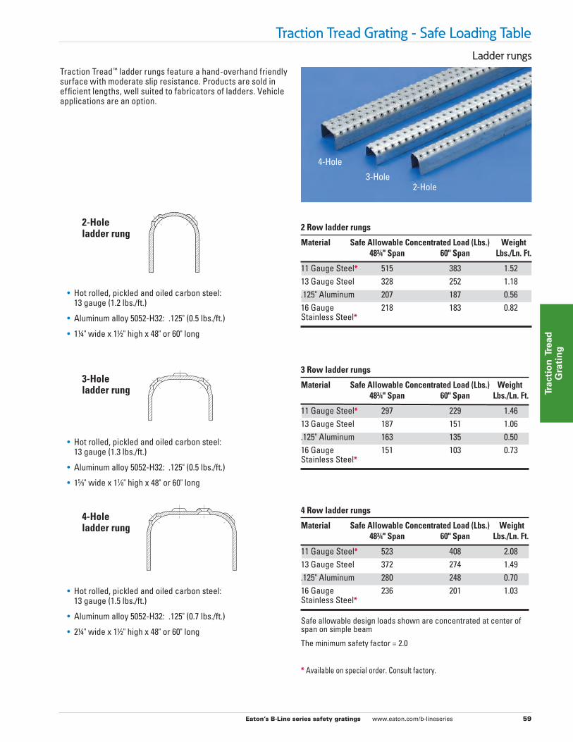
Ladder rungs
Traction Tread Grating - Safe Loading Table
4-Hole
3-Hole2-Hole
Traction Tread™ ladder rungs feature a hand-overhand friendly surface with moderate slip resistance. Products are sold in efficient lengths, well suited to fabricators of ladders. Vehicle applications are an option.
• Hot rolled, pickled and oiled carbon steel: 13 gauge (1.2 lbs./ft.)
• Aluminum alloy 5052-H32: .125" (0.5 lbs./ft.)
• 11/4" wide x 11/2" high x 48" or 60" long
• Hot rolled, pickled and oiled carbon steel: 13 gauge (1.3 lbs./ft.)
• Aluminum alloy 5052-H32: .125" (0.5 lbs./ft.)
• 15⁄8" wide x 11⁄8" high x 48" or 60" long
• Hot rolled, pickled and oiled carbon steel: 13 gauge (1.5 lbs./ft.)
• Aluminum alloy 5052-H32: .125" (0.7 lbs./ft.)
• 21/4" wide x 11/2" high x 48" or 60" long
2-Holeladder rung
3-Holeladder rung
4-Holeladder rung
2 Row ladder rungs
Material Safe Allowable Concentrated Load (Lbs.) Weight 483/4" Span 60" Span Lbs./Ln. Ft.
11 Gauge Steel* 515 383 1.5213 Gauge Steel 328 252 1.18.125" Aluminum 207 187 0.5616 Gauge 218 183 0.82Stainless Steel*
Safe allowable design loads shown are concentrated at center ofspan on simple beam
The minimum safety factor = 2.0
3 Row ladder rungs
Material Safe Allowable Concentrated Load (Lbs.) Weight 483/4" Span 60" Span Lbs./Ln. Ft.
11 Gauge Steel* 297 229 1.4613 Gauge Steel 187 151 1.06.125" Aluminum 163 135 0.5016 Gauge 151 103 0.73Stainless Steel*
4 Row ladder rungs
Material Safe Allowable Concentrated Load (Lbs.) Weight 483/4" Span 60" Span Lbs./Ln. Ft.
11 Gauge Steel* 523 408 2.0813 Gauge Steel 372 274 1.49.125" Aluminum 280 248 0.7016 Gauge 236 201 1.03Stainless Steel*
* Available on special order. Consult factory.

Eaton’s B-Line series safety gratings www.eaton.com/b-lineseries 60
Traction
Tread
Gratin
g
Traction Tread Grating - Accessories
Assembly 1. Align Traction Tread™ planks on I-beam or other
anchoring cross-member.
2. Mark the I-beam for drilling purposes under the third or fourth hole from the end of the Traction Tread plank. Drill a pilot hole.
3. Remove Traction Tread plank and drill a finish hole.
4. Drill out the hole in Traction Tread plank.
5. Replace Traction Tread plank to its original position. Run bolt through Traction Tread plank and I-beam. Tighten with washer and nut until secure.
6. Test for movement or slippage. If Traction Tread planks are not secure, check fastening system for loose or missing parts. Repeat steps 1 thru 5.
Note: Do not walk on Traction Tread planks if they are not secure. Serious injury could result.
Welding A common method of fastening safety grating is welding. It is
recommended that all B-Line series safety grating products be fillet welded.
For more information, consult technical services.
Source Locally(1) 3⁄8"-16 Carriage bolt **
(1) 3⁄8" Flat washer
(1) 3⁄8"-16 Hex nut
Carriage Bolt
Flat Washer
Hex Nut** Plank carriage bolt lengths = Side Channel Height + 1"
Field drilling is required.

Eaton’s B-Line series safety gratings www.eaton.com/b-lineseries 61
Trac
tio
n T
read
G
rati
ng
Traction Tread Grating - Specifications
Notes to architect 1. Traction Tread™ is intended for general purpose use in plants and
process facilities by industry, commerce, and public facilities, for both mobile and stationary equipment.
2. Traction Tread stair treads are intended for utility stairs and fire escapes in commercial, public and private buildings where local code permits.
3. These specifications are presented as a general guide to the architect or structural engineer in preparing project specifications. Allowable loads, spans and other limiting conditions presented in this catalog offer product data for use in design and construction.
4. All supports should provide a smooth, level, 11/2" minimum bearing surface, free of burrs, bridging, welds or other irregularities.
5. Random cut ends and diagonal or circular cut exposed edges should be banded with a bar at least 1⁄8" thick and equal to the overall side channel depth of grating welded at contact points at the discretion of the design engineer.
6. Bolted connections, except stair or ladder tread attachment to stringer channels, may be replaced by welded connections that develop the same strength.
Part 1: General 1.1 Scope The contractor shall furnish and install Traction Tread as
specified and shown on the drawings. 1.2 Qualifications Traction Tread sheets, planks, ladder rungs, stair treads
and accessories, unless otherwise indicated, shall be manufactured by Eaton's B-Line Division, and shall be installed in accordance with its current printed directions. Safety surface shall be slip-resistant in all directions.
1.3 Submittals The contractor shall furnish shop drawings of grating layout,
framing and supports, unit dimensions and sections, type and location of fasteners and welds.
1.4 Storage and handling All materials shall be stored and handled to avoid damage.
Damaged materials shall be removed from the premises.
Part 2: Products 2.1 Flooring materials a. Type: Traction Tread Flooring b. Metal and Finish: (carbon steel — hot rolled, pickled and
oiled, ASTM A1011) (aluminum, alloy 5052-H32) c. Metal gauge: (14-ga. HRPO steel) (13-ga. HRPO steel) (12-ga.
HRPO steel) (11-ga. HRPO steel) (16-ga. HRPO steel)(14-ga. stainless steel) ( .125" aluminum)
d. Sheet Size: (36" x 120") 2.2 Plank grating a. Type: Traction Tread plank b. Metal gauge and type: (11 and 13 gauge carbon steel —
hot rolled, pickled and oiled, ASTM A1011) (11 and 13 gauge mill-galvanized steel — ASTM A924), (.125" aluminum, alloy 5052-H32)
2.3 Ladder rungs a. Type: Traction Tread ladder rungs b. Metal gauge and type: (13 gauge mill-galvanized steel,
ASTM A924) (13 gauge carbon steel — hot rolled, pickled and oiled, ASTM A1011) (.125" aluminum, alloy 5052-H32) (14 gauge stainless steel, alloy types 304-2B/D)
c. Width: (11/4") (15⁄8") (21/4") d. Length: (48") (60")
Part 3: Execution 3.1 Condition of surfaces Prior to Traction Tread installation, contractor shall inspect
supports for correct size, layout and alignment and verify that surfaces to receive grating are free of debris. The contractor shall report to the design or consulting engineer or owner’s agent in writing any defects considered detrimental to proper application of Traction Tread so defects can be remedied before grating is applied.
3.2 Traction Tread installation Install Traction Tread in accordance with manufacturer’s
recommendations and shop drawings. Sheet goods by their nature are intended to cover surface only. They require adequate support and hold down. Position Traction Tread planks flat and square with ends bearing min. 11/2" on supporting structure. Keep Traction Tread sections at least 1/4" away from vertical steel sections and 1/2" from concrete walls. Installation clearances are built into this product. Allow clearance at joints between sections of max. 1/4" at side channels and max. 3⁄8" at ends. When specified, band random cut ends and diagonal or circular cut exposed edges with a min. 1⁄8" thick bar welded at contact points.
3.3 Stair Tread Installation Install Traction Tread stair treads as shown on the drawings.
Fasten treads to stair stringers with 3⁄8" x 1" machine bolts and nuts. a. For stair treads, intermediate stringer is recommended for
spans over 4 feet.
How to build a part number: T - TT- 7 15 13 GL
Width 7"10"12"
Gauge.125" AL1113
MaterialAL = AluminumGL = Galv. Steel
Traction tread
Channel depth15 = 11/2"20 = 2"
Stair tread