
Design-In Environmental Health and Safety … In Environmental Health and Safety Specification for...
47
Design-In Environmental Health and Safety Specification Version 2.0 June 2013
Transcript of Design-In Environmental Health and Safety … In Environmental Health and Safety Specification for...

Design-In
Environmental
Health and Safety
Specification
Version 2.0 June 2013

Design In Environmental Health and Safety Specification for Suppliers Version 2.0 __________________________________________________________________________________
June 2013 2 Delphi Corporation
Table of Contents
1. GENERAL………………………………………………………………………………………………………………3
2. HIERARCHY OF HEALTH & SAFETY CONTROLS……………………………………………………………...5
3. EQUIPMENT RISK ASSESSMENT…………………………………………………………………………………8
4. WORKSTATION DESIGN/OPERATOR INTERFACE…………………………………………………………..10
5. MAINTENANCE……………………………………………………………………………………………………...13
6. FALLS AND WORKING SURFACES……………………………………………………………………………..15
7. INDUSTRIAL HYGIENE…………………………………………………………………………………………….16
8. SAFEGUARDING……………………………………………………………………………………………………24
9. ENERGY CONTROL AND LOCKOUT……………………………………………………………………………32
10. ROBOTIC CELL……………………………………………………………………………………………………..37
11. SERVO CONTROLLED EQUIPMENT AND MACHINING CELLS……………………………………………43
ANNEX A: SAFE DISTANCE FROMULAS…………………………………………………………………………….47

Design In Environmental Health and Safety Specification for Suppliers Version 2.0 __________________________________________________________________________________
June 2013 3 Delphi Corporation
Design In Health and Safety Specification for Suppliers 1.0 General 1.1 Scope
This specification contains health and safety requirements for the design and redesign of industrial equipment and systems used in processing or manufacturing at Delphi Corporation. This specification applies, but is not limited to assembly workstations/cells, standard/custom built machines, conveyors, spray booths, ovens, process equipment, material handling equipment, robotic systems, and all related manufacturing systems.
This specification is organized into four segments as follows:
• Machine and Equipment Design & Design-In Safety (sections 1-3)
• Human Interface Applications (sections 4-7)
• Specific Hardware Applications (sections 8 - 9)
• Specific Manufacturing Process Applications (sections 10 - 11)
1.2 Purpose
The purpose of this specification is to communicate to Delphi equipment suppliers the mandatory Health and Safety requirements including:
Ergonomics
Electrical
Manual Controls
Fall Hazard Control & Working Surfaces
Industrial Hygiene
Safeguarding
Energy Control & Lockout
Robotic Cells
Servo Controlled Equipment and Machining Cells
Which are expected to be addressed during equipment design / build in order to achieve a safe operating environment for all personnel.
1.3 Application
The requirements of this specification shall be applied to:
New Machine & Equipment and Manufacturing Systems
New Machine & Equipment includes the design, engineering, construction, and functional test of the equipment. Equipment utilized in a new manufacturing system includes newly manufactured Machines & Equipment purchased for the new system, also applies to off the shelf purchased equipment
Remanufactured Machines & Equipment
Remanufactured Machines & Equipment is equipment that is being mechanically, electrically and/or fluid power rebuilt/refurbished to an as-new state.

Design In Environmental Health and Safety Specification for Suppliers Version 2.0 __________________________________________________________________________________
June 2013 4 Delphi Corporation
1.4 Supplier Design for Environmental Health & Safety Deliverables
These requirements are expected to be reflected in the quote and must be fulfilled at the time of machine qualification. Deliverables include: 1) Equipment Risk Assessment Documentation (including Machine Guarding) 2) Industrial Hygiene (including conformance to radiation sources and laser spec) 3) SL 1.0 Noise Requirements (and run off form) 4) Machine Control information for pollution control equipment 5) Fire Detection/Suppression information
6) Material Safety Data Sheets (see requirements) for direct and indirect materials (including (lubrication, Coolant/Quench etc.)
7) Ventilation requirements 8) Ergonomics assessment
9) Equipment Qualification EHS Checklist These documents will be reviewed for accuracy, completeness to ensure they meet Delphi’s requirements. The latest versions of the supplier specification / requirements are located on the Delphi Supplier Site. If you require additional information or have questions please refer to the www.DelphiSuppliers.com. Click on “vender documents” and then Corporate Requirements for all Machinery/Equipment builders. Divisions may have additional requirements or addendums listed under their respective divisional name

Design In Environmental Health and Safety Specification for Suppliers Version 2.0 __________________________________________________________________________________
June 2013 5 Delphi Corporation
2.0 Hierarchy of Health and Safety Controls
The hierarchy that Delphi uses represents the fundamental principles that govern the application of safety designs, which eliminate or reduce risk caused by exposure to hazard(s) based on specific task(s) performed. This specification is based on the hierarchy principles.
The hierarchy consists of five levels—arranged in order from the most effective to the least effective—as shown in Figure 2-1. The preferred method of controlling hazards is via a level 1 or 2 control.
Figure 2-1: Hierarchy of Health and Safety Controls
2.1 Applying the Hierarchy of Health and Safety Controls
Design in Environmental Health and Safety begins with a thorough understanding of the work to be performed, evaluation of the hazards and exposures associated with work tasks, and establishment of the most effective Health &Safety controls to eliminate or minimize these hazards.
Safety for all processes, cells, and machines shall be addressed through the Hierarchy of Health and Safety Controls. The following examples are intended to provide a better understanding of the hierarchical approach.
1. Elimination or Substitution:
a. Eliminate equipment
b. Simplify equipment
c. Improve initial equipment design
d. Remove/minimize human interaction with equipment
e. Eliminate pinch points
f. Eliminate or simplify material handling
g. Place adjusting devices and other requirements for human interaction outside the hazard area
h. Substitute less hazardous processes and/or chemicals
2. Engineering Controls:
a. Perimeter guards
b. Light curtains
c. Safety mats
1. Elimination or Substitution
2. Engineering Controls
3. Warnings
4. Training and Procedures(Administrative Controls)
5. Personal ProtectiveEquipment
Most
Effective
Least
Effective

Design In Environmental Health and Safety Specification for Suppliers Version 2.0 __________________________________________________________________________________
June 2013 6 Delphi Corporation
d. Interlocks
e. Safety relays, switches and other control devices
f. Ventilation, local or point of operation exhaust
g. Automatic/Manual material handling (e.g. lift for ergonomics issue)
h. Movable interlocked guard
3. Warnings:
i. Lights, beacons and strobes
j. Computer warnings
k. Signs
l. Markings indicating a restricted space on the floor
m. Equipment start-up alarms, beepers and horns
n. Labels
4. Training and Procedures (Administrative Controls)
o. Safe operating practices and procedures
p. Standardize Work
q. Job rotation
r. Written training programs
Note: Written training, procedures, and administrative controls are used when higher-level alternatives are not feasible, and when the risk is adequately controlled. Personnel must be properly trained before operating and maintaining equipment. This includes being provided with up-to-date and accurate written instructions (Safety, Standardized Work, Set-up, Start-up, Run, Stop, etc.). The training and instructions must be implemented, enforced and followed.
5. Personal Protective Equipment (PPE):
a. Face shields
b. Safety glasses
c. Hearing protection
d. Gloves
e. Protective sleeves
f. Respirators
g. Welding screens
h. Expendable tools
2.2 The Goal of the Hierarchy of Health and Safety Controls It is important to emphasize that Delphi’s goal is to eliminate hazards whenever possible; or minimize hazards through substitution or design changes in order to contain, control, or eliminate the hazard. This is best accomplished during the equipment design phase and through a coordinated effort between Delphi and the equipment supplier’s engineers.

Design In Environmental Health and Safety Specification for Suppliers Version 2.0 __________________________________________________________________________________
June 2013 7 Delphi Corporation
3.0 Equipment Risk Assessment The supplier must provide in electronic form a Risk Assessment for the piece of equipment being supplied to Delphi. If the equipment is specified as “build to print”, then Delphi will be responsible for completing the Risk Assessment.
The Risk Assessment must comply with International Organization for Standardization--ISO 14121-1 elements as described in the following figure. The FMEA risk assessment format that Delphi uses is available on the www.delphisuppliers.com website.
3.1 Supplier’s Risk Assessment must include as a minimum:
Supplier’s Contact Information. Name and contact information of the person or team that performed the risk assessment
3.2 Boundary definition.
The limits of the machine must be defined in the first step:
Space limits: for example clearance, space required for installation and maintenance, man-machine interface, machine-power supply interface.
Use limits: intended use of the system, including the modes of operation, application phases and different intervention phases by users, as well as reasonably foreseeable misuse.
Time limits: probable lifetime of the machine and its components, taking proper use into consideration.
3.3 Hazard identification.
When identifying the hazards, the following aspects are to be taken into consideration in particular:
Hazards during all life phases and modes of operation of the machine (including planned / routine maintenance).
Interaction between machine and system personnel, other machines and their energy supply Possible malfunctions on the machine. Proper use of the machine and its components. The physical characteristics of the system personnel and their level of training.
Design In Environmental Health and Safety Specification for Suppliers Version 2.0 __________________________________________________________________________________
June 2013 8 Delphi Corporation
3.4 Risk Estimation Risk estimation takes place after all the hazards have been identified. The probability of the occurrence of a possible harm, in turn, is dependent on the exposure of the person to the hazard, the occurrence of the hazardous event and the possibility of avoiding or limiting the harm.
Two frequently-used methods for investigating hazards and estimating risks are the failure mode and effects analysis as well as the risk graph. Delphi has developed a methodology that is task based and complies with the elements described in this specification. Click here for Risk Assessment for the methodology and form
3.5 Risk Evaluation
After risk estimation, a risk evaluation must be conducted in order to decide whether risk reduction is necessary or whether adequate safety or an acceptable residual risk has been attained. While the actual risk can be defined to a large extent by experts, the acceptable residual risk may vary in accordance with applicable regulatory requirements.
Since the risk evaluation is determined by subjective viewpoints, and in the absence of specified regulatory limits, a competent professional is needed to define an acceptable residual risk based on prior experience. Industry standards, guidelines, expert opinions as well as accident statistics should be considered in the process. A critical component of the Risk Assessment process is to ensure that the acceptable risk threshold is based upon sound technical understanding and state of the art knowledge.
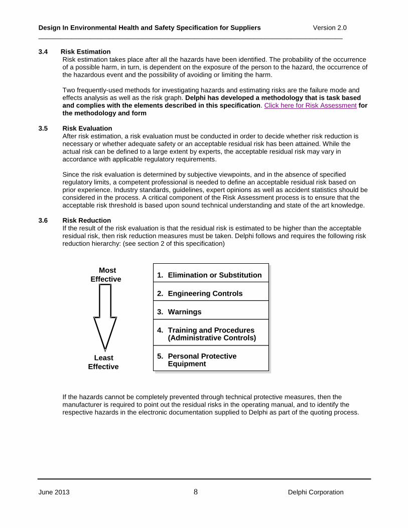
3.6 Risk Reduction
If the result of the risk evaluation is that the residual risk is estimated to be higher than the acceptable residual risk, then risk reduction measures must be taken. Delphi follows and requires the following risk reduction hierarchy: (see section 2 of this specification)
If the hazards cannot be completely prevented through technical protective measures, then the manufacturer is required to point out the residual risks in the operating manual, and to identify the respective hazards in the electronic documentation supplied to Delphi as part of the quoting process.
1. Elimination or Substitution
2. Engineering Controls
3. Warnings
4. Training and Procedures(Administrative Controls)
5. Personal ProtectiveEquipment
Most
Effective
Least
Effective

Design In Environmental Health and Safety Specification for Suppliers Version 2.0 __________________________________________________________________________________
June 2013 9 Delphi Corporation
4.0 Workstation Design/Operator Interface
Ergonomics-related-injury/illness is a major subset of all health & safety incidents observed in industrial and manufacturing environments. A key strategy for reducing the number of ergonomics related injuries/illnesses is to integrate ergonomics consideration early in the equipment and process design stage. Not only will the early integration of ergonomics minimize injury risk factors, it will also improve the performance factors of all those who operate or interact (maintenance, skilled trades, and material handlers) with the equipment/process.
Equipment suppliers to Delphi must provide equipment, workstations, hand tools, etc that meet the Delphi Ergonomics Requirements. These requirements are documented in the Design-In Ergonomics Guideline (DEG). Delphi Internet Supplier Site
Ergonomic risk factors are:
Forceful exertion
Awkward postures
Mechanical stress
Repetition
Static muscle loading
Environmental stressors
The following sections (4.1 – 4.4) highlight some of the principle ergonomics considerations covered in the Delphi Design-In Ergonomics Guideline.
4.1 Workstation Design
Posture Issues
Part orientation from process to process should allow for neutral posture (for example, minimize flipping/rotating of part)
Operator must be able to work facing the work station; operator should not have to work facing sideways
Eliminate or reduce:
Above-the-shoulder motions
Need to re-orient or re-grasp parts
Need for operator to bend neck greater than 20° o Need for operator to bend or rotate torso greater than 20° o Extended reaches (forward, to the side, or behind the operator)
Parts should be presented/designed so: o The hand span of the grasp is less than 3” (7.6 cm); if greater, than a two hand grasp is
required o A full hand power grip is used (as opposed to a pinch grip with the fingers)
Properly locate buttons, lights, handles, and levers to reduce posture deviations and force requirements
4.2 Workplace Issues
Provide adequate clearance for hands and feet; if operator is wearing gloves, increase clearance by 0.5” (1.3 cm)
One handed lifting greater than 6 lbs. (3 kg) requires additional analysis
Two handed lifting with a lift moment greater than 245 in-lbs. requires additional analysis (lift moment is weight of object times horizontal distance of the object away from body)

Design In Environmental Health and Safety Specification for Suppliers Version 2.0 __________________________________________________________________________________
June 2013 10 Delphi Corporation
Designing for an adjustable range is the preferred method where practical.
Sit/Stand workstation is the preferred design for most situations (a workstation that can accommodate a seated or a standing operator)
An equipment layout plan that requires operators to turn 180 degrees on a repetitive basis should be avoided; other layout options that provide a more suitable walk pattern for operators should be considered.
Design equipment so that the operator does not have to bend, stoop, or otherwise alter their posture in order to load fixture or operate equipment.
Delphi strongly discourages the use of foot pedals in standing operations. The only condition where they would be accepted is if all possible alternatives have been exhausted. Constant pressure of force required to activate a foot pedal under any circumstances during an assembly operation is not acceptable.
Any object to be frequently grasped should be located within 6-14 inches (15-36 cm) of the front of the work surface.
Large or heavy objects (greater than 6 lbs., 2.7kg, per hand) need to be located close to the front of the workplace.
It is permissible to have an operator occasionally (a few times an hour) reach to procure something outside the work area, but such reaches should not be made a regularly occurring part of a brief work cycle.
Design material locations to be within appropriate operator reach envelopes.
Operators should not reach behind their body repetitively, and no more than 10º infrequently.
Operator should be able to supply the machine while keeping both feet firmly on the ground (no platform or steps)
Keep the number of controls to a minimum.
The movements required to activate them should be as simple and easy to perform as possible, except where resistance should be incorporated to prevent accidental activation.
Identification labels should be placed above the control and identical labels above the display.
If one hand must operate several controls in sequence, arrange the controls to allow for continuous movement through an arc (if this arrangement does not violate any of the basic rules of workstation maximum reaches).
Assign controls to the hands if they require precision or high-speed operation. When there is only one major control that, at times, must be operated by either hand or both hands, place it in front of the operator, midway between the hands.
Handedness is important only if a task requires skill or dexterity. If the control requires a precision movement, place it on the right, since 90% of the population is right handed.
Distinguish between emergency controls and displays and those that are required for normal operations by using the following techniques: separation, color-coding, clear labeling or guarding.

Design In Environmental Health and Safety Specification for Suppliers Version 2.0 __________________________________________________________________________________
June 2013 11 Delphi Corporation
Emergency controls should be easily accessible and within 30o horizontally of the operator’s normal line of sight.
Controls for set-up, supplemental activities and/or maintenance should be vertically located between 35-65 inches (89-165 cm) above the standing surface.
Single controls (wobble sticks, whisker switches) should be placed at approximately the same height as where the operator performs work.
Dual controls for cyclical operator use in a standing position should be vertically located between 36 to 42 inches (91 to 107 cm) above standing surface.
Display Devices
Visual information on display screens must be located within the central field of vision of an operator of average height
Display devices should be height adjustable
Fixed light signals must be located within an operator’s central field of vision.
Flashing signals must be located within the peripheral field of vision, but must not flash permanently
The flicker frequency of a flashing signal must enable it to be distinguished from a fixed light signal
4.3 Vibration
Hand-Arm vibration is defined as the mechanical vibration that, when transmitted to the human hand-arm system, entails risks to the health and safety of workers, in particular vascular, bone or joint, neurological or muscular disorders
Whole Body vibration is defined as the mechanical vibration that, when transmitted to the whole body, entails risks to the health and safety of workers, in particular lower-back morbidity and trauma of the spine
Equipment should be designed and built so that any vibration transmitted to the operator is reduced to the lowest possible level, minimizing any risk to the operator. This includes hand tools that could transmit hand-arm vibration.
Country specific or local plant vibration directives may take precedence over these guidelines.
4.4 Inspection, Maintenance, Repair
At each location anticipated for the performance of a maintenance operation on the machine, the available space shall be sufficient for the operator to:
- not only access the machine components, - but also carry out the necessary operations in a space which enables the operator to move
without external constraint, including when wearing Personal Safety Equipment, - and also work in comfortable conditions (for example, stable footing).
If machine components can only be dismantled at a certain height or are situated overhead, the supplier will specify the appropriate devices to be used not only for access but also for work at the maintenance position (for example, hoist, ladder with flat, non-slip rungs built into the device, platform, etc.).

Design In Environmental Health and Safety Specification for Suppliers Version 2.0 __________________________________________________________________________________
June 2013 12 Delphi Corporation
5.0 Maintenance
This section provides design guidelines to enhance safety as it pertains to the maintenance of machinery and equipment. The focus is on providing safe, easy, and quick access for operators, skilled trades, and other personnel who may perform machinery maintenance.
5.1 Requirements
The following requirements enhance safety while performing maintenance on work cell equipment. The supplier shall work with the responsible engineer to ensure the following requirements are met:
1. All energy-isolating devices on each piece of equipment shall be placed at the access points to minimize the time and travel required for a proper system/safety lockout and restart.
Note: For minimum height, reference Design-In Ergonomics Guideline (DEG) under Corporate requirements. International references include International Organization for Standardization--ISO 9241, 11226 and 11428.
2. Provide safe access and working space as well as clear visibility within and around all control panels.
Note: This should apply to all controls including electrical, pneumatic, hydraulic, and mechanical.
3. Locate and mount the system function controls and monitoring devices outside the hazardous area while ensuring clear visibility, reference Lean Equipment Design. Ergonomic factors regarding posture and visual requirements shall be considered, reference Design-In Ergonomics Guideline DEG under Corporate Requirements.
Examples of these devices are as follows:
Lubrication fill and monitoring
Valves and flow controls
Meters and gages
Diagnostic equipment
Hydraulic units
Operator interface device
4. Equipment design shall consider the following mechanical safety issues:
Eliminate the potential for stored energy, such as: Hydraulic Accumulators Pneumatic Pilot operated checks Blocked center valves Standard ball valves Spring Loaded (coil, torsional, etc.) Vertical Loads Counter balance valves Rod brakes Shot pins
Eliminate sharp edges on all surfaces except where required (e.g. tooling)
Counter-balance weights and cables
5. Eliminate/control exposure to hazardous motion for tasks that require the equipment to be in the automatic mode in order to perform the task (e.g., vibration analysis requires either safe access for measurement or permanently mounted transducers, infrared diagnosis, etc.).

Design In Environmental Health and Safety Specification for Suppliers Version 2.0 __________________________________________________________________________________
June 2013 13 Delphi Corporation
Note: By eliminating or controlling personnel exposure to hazardous motion, analysis, troubleshooting, or planned maintenance procedures can be safely performed.
6. Design to eliminate maintenance tasks that require climbing to or working at an elevated location. If this is not possible, other fall prevention and/or protection measures must be provided, reference the requirements listed in Section 6, Falls and Working Surfaces.
7. Provisions shall be made for direct, task (maintenance) lighting as part of a system to provide greater visibility during routine maintenance and service, reference Design-In Ergonomics Guidelines DEG under Corporate Documents on www.delphisuppliers.com.
8. Identify hazard zones (e.g., areas that are not completely enclosed within safeguards) by utilizing the following methods, as applicable:
Painted floor markings
Column markings
Flashing lights to indicate the unsafe area
This identification reduces the potential for injury in areas of risk outside the normal traffic patterns.
9. Specify the detailed training for proper maintenance and service techniques on all equipment and/or systems. In the interest of both safety and efficiency, proper preventive maintenance and repair training are a necessity.
10. Provide a detailed list of preventive maintenance tasks including specific safety precautions (to be added to the site Preventative Maintenance recordkeeping system).
11. To ensure that maintenance and service tasks can be safely performed, training shall be provided for all new manufacturing systems. Specific equipment training shall be identified by the supplier and / or the risk assessment team during the design-in risk assessment.
5.2 Design for Electrical Safe Work Practices
To enhance safety while performing maintenance on electrical equipment, the design shall include hazard control for identified electrical maintenance and troubleshooting tasks. These hazards typically include electrical shock and/or arc flash/blast.
Safe Work Practices for the control of electrical hazards include, but are not limited to, the following:
Safe Operating Procedure,
Establishing safe approach distances,
Electrical testing, and
Use of appropriate Personal Protective Equipment.
Electrical equipment shall be designed to control the exposure to shock and arc flash hazards. The following items may be part of the design:
Arc-flash limiting devices
Low voltage control system
Proper safety grounding
Protective shields and barriers
Touch-safe components
Physical separation of hazardous voltage levels

Design In Environmental Health and Safety Specification for Suppliers Version 2.0 __________________________________________________________________________________
June 2013 14 Delphi Corporation
Access for programming/diagnostics to be provided external to enclosure, reference DA-2004 on www.delphisuppliers.com.
For additional information on electrical safe work practices, see Delphi’s Standard for Electrical Safe Work Practices - ESWP, which is available on the archived documents tab of the www.delphisuppliers.com website.
6.0 Falls and Working Surfaces
This section identifies the design requirements for the prevention of falls and the control of fall hazards.
Historical data indicates that falls are one of the leading causes of occupational fatalities and serious injuries. The vast majority of these incidents occurred while employees were climbing or working at elevations. Consideration of potential fall hazards during the design stage with a focus on fall prevention vs. fall protection will eliminate or reduce hazards and future retrofit costs. It will also facilitate quick preventive maintenance task completion.
6.1 Fall prevention and protection from elevations
Whenever performance of any task would allow a worker to fall a distance of 1.8 m (6ft.) or more, fall prevention or protection measures must be designed-in to prevent the potential for a fall. Tasks that expose a worker to a fall hazard from 0.4 m (16 inches) to 1.8 m (6ft.) and > 1.8 m (6ft.) shall use fall prevention techniques to eliminate the potential for a fall unless other wise specified in the Machine & Equipment purchase specification. Work platforms that are 0.4 m (16 inches) and higher must have appropriate means of access. Stairs are the preferred means of access.
The following shall be considered during the fall prevention design-in process:
1. The shutoff valves, controls, monitoring equipment, maintenance service apparatus, and similar items should be located at readily accessible floor or grade levels.
If this is not possible, anchorage points shall be installed in order to protect personnel working at elevations.
2. Overhead equipment or machinery on rails shall be designed so that it can be positioned for maintenance or repair in an area where fall hazards are controlled.
3. A means of access/egress shall be designed for maintenance and service that cannot be performed at readily accessible floor or grade levels. The design shall provide a means for safe access that reflects an anticipation of unplanned maintenance events and engineering of fall prevention measures.
4. The following climbing devices shall be used in the order listed below. These devices shall meet all applicable country specific laws and regulations:
a. Fixed stairs
b. Alternating tread-type stairs: These stairs should be used in limited space applications.
They are designed at inclines of 50 -70 and equipped with handrails.
c. Stairways, guarded platforms, and ramps provide safer access than portable lifting devices and ladders. All steps, ramps, and working surfaces should have a “non-slip” surface.
d. Methods for moving tools and equipment to elevated areas shall be a part of the design.
5. A means of anchorage shall be designed, installed and properly labeled for personal fall arrest systems when fall hazards cannot be eliminated or controlled.
6.2 Walking and Working Surfaces
1. All equipment shall be manufactured with the expectation that it will not leak equipment fluids or process fluids. 2. Equipment that has the potential to create condensation should have containment and/or insulation

Design In Environmental Health and Safety Specification for Suppliers Version 2.0 __________________________________________________________________________________
June 2013 15 Delphi Corporation
to control the potential for a slip/fall hazard.
7.0 Industrial Hygiene
7.1 Chemical Material Approval
A basic premise of Delphi’s Hierarchy of Health and Safety Controls requires that equipment and processes be designed to minimize the use of chemical materials that require atmospheric controls, costly disposal measures, personal protective equipment, and have the potential for worker exposure through inhalation, ingestion, or skin contact.
All chemical materials used in process equipment, machinery, and instrumentation must be approved prior to use at a Delphi facility. Examples include machine oils, bearing greases, lubricants, hydraulic fluids, inert gases, fire suppression gases/foams, mold cleaners, and manometer fluids.
All chemical materials intended to be used by a contract service at Delphi must be approved prior to use AND removed from the site at the completion of work.
Although chemical approvals are responsibility of the Delphi engineer, Suppliers need to be aware of specific Delphi requirements and approval limitations:
1. All chemical materials used in production, research, and/or maintenance activities at ALL Delphi facilities must be approved by the local Delphi Hazardous Material Review Committee prior to purchase and use.
2. Chemical material approvals apply only to the specific use for which it was approved at a given site. Approval does not automatically transfer to include the use of the same material at another Delphi location. Separate approvals are required for each proposed use at each proposed location.
3. Material Safety Data Sheets are required for all approvals and must meet Delphi minimum requirements located at:
a. https://delphi.portal.covisint.com/web/portal/fud/-/journal_content/56_INSTANCE_WREV/107627/114800#guidelines
7.2 Process Ventilation
All new equipment and processes that are potential sources of airborne chemical, physical, and biological hazards are evaluated to determine the need for process ventilation. This assessment is coordinated by the Delphi Engineer with input from the Supplier and other Delphi staff members, as appropriate.
Process ventilation that accompanies equipment / processes shall meet the following basic requirements; more specific requirement may be specified.
Local exhaust ventilation systems shall be the preferred method for the removal of airborne hazards when one or more of the following conditions exist:
contaminants are hazardous in nature,
emission rates are high and variable,
workers are located next to emission sources, and
the physical nature of contaminant requires it, e.g., heavy particulate
General ventilation for the purpose of contaminant dilution is an option provided when all of the following conditions exist:
the contaminants are of a low hazard nature
emission rates are low and uniform
the emission source(s) is remote from the worker(s), and

Design In Environmental Health and Safety Specification for Suppliers Version 2.0 __________________________________________________________________________________
June 2013 16 Delphi Corporation
the physical nature of contaminant is a gas or vapor
Design goal
When controlling contaminants through process ventilation, personal exposures shall be reduced as low as reasonably achievable and no greater than 1/10th of the applicable permissible exposure limit. This is in accordance with the American National Standards Institute—ANSI Z9.2—2006 Fundamentals Governing the Design and Operation of LEV.
Process ventilation systems shall be designed and installed so as to reduce or eliminate additional health and safety hazards that may be created, for example, during periodic maintenance (falls, confined spaces, etc).
All ventilation designs shall incorporate the standards and specifications noted in the Delphi Corporate Fire and Security Manual, as applicable. Although it is the responsibility of the Delphi engineer to identify these requirements during the Request For Quote (RFQ) process Suppliers should be vigilant to inquire when ventilation systems are related to; engine testing and associated operations; painting, coating, drying and associated operations, and; welding, cutting, grinding, and other hot work. Other requirements related to the fire protection, operation, inspection, and maintenance of ventilation systems may also be stipulated in the Request For Quote (RFQ).
Design principles & parameters
Process ventilation systems shall be designed in accordance with established principles of air flow following a recognized design methodology. The velocity pressure design methodology found in “Industrial Ventilation: A Manual of Recommended Practice”, published by the American Conference of Governmental Industrial Hygienists (ACGIH) is preferred.
Canopy exhaust hoods are not appropriate at employee workstations because of their tendency to draw contaminants through a worker’s breathing zone.
Exhaust stack height, location, and exit velocity shall be designed to minimize the reintroduction of exhaust emissions into the facility.
In general all process ventilation exhaust should be exhausted to the outside of the facility. Air that is re-circulated from process ventilation shall meet the criteria described in American National Standards Institute--ANSI Z9.7, Recirculation of Industrial Process Exhaust Systems.
A ventilation performance monitor, such as an aneroid static pressure gauge, shall be installed and located at a point visible to workers, such as near the operator’s work station(s). This gauge shall be color-coded to indicate the following:
Normal operating condition (recommended color – green) Change filter condition (recommended color – yellow) Immediate service condition (recommended color – red)
Acceptance testing and commissioning
All systems will be performance tested post-installation to determine if equipment and systems provided are operating in a reliable and satisfactory manner. Operating parameters such as airflow rate(s), hood static pressure(s), filter differential pressure, and fan amps shall be determined and recorded for future reference. Supplier documentation shall include how and where performance measurements were obtained.
Systems operating at less than 95% of the design volume shall be corrected prior to acceptance.
Multiple copies of an as-installed drawing shall be provided to the Delphi engineer.
The supplier shall provide a ventilation system maintenance schedule that includes criteria for the servicing and/or replacement of air filtration elements (filters, sorbents, etc), where applicable

Design In Environmental Health and Safety Specification for Suppliers Version 2.0 __________________________________________________________________________________
June 2013 17 Delphi Corporation
7.3 Mist Control
Significant respiratory effects have been associated with worker exposure to the mist / aerosol generated by machining operations. In order to minimize exposure to Delphi workers the following design principles shall be incorporated into supplier equipment for the purpose of reducing mist / aerosol levels:
Fluid delivery
All metal removal fluids shall be intrinsically safe fluids with low misting characteristics
Cycle coolant on and off as required for machining or flushing chips.
Minimize fluid delivery pressure (velocity) and flow rate (GPM).
Minimize and remove contaminants in order to preserve the tools.
Provide covers for coolant tanks
Machine tool design
Employ efficient chip shedding and control methods
Whenever possible machine tool design should minimize tool and wheel speed
Machine enclosure design
The machine enclosure must be capable of containing within its envelope the mist and vapor produced within that envelope while operating under the design airflow.
Enclose the process as completely as possible to minimize exhaust requirements while allowing for easy access to maintain the machine and provide tool changes.
Automatic opening and closing doors shall be incorporated for loading and unloading parts, where feasible.
Incorporate a perimeter slot draw possible across the highest point on the machine enclosure, where feasible.
Make-up air inlets shall be strategically placed and below the point of metal cutting with a minimum in-draft velocity of 250 feet (76 meters) per minute. Inlets location and design should not allow coolant to splash out or become obstructed with chips. Exhaust volume requirements should be determined to ensure that all cracks and un-sealable openings have an in-draft velocity of 250 feet (76 meters) per minute.
Ductwork design
The design shall be leak-free (no spiral duct or duct with mechanical seams)
Employ heavy duty industrial construction (~16-18 gauge, should the duct fill with liquid). All gasket and seal materials should be compatible with the metal removal fluids.
Slope the ductwork toward the mist collector to minimize the use of traps or airlocks, where feasible. If traps are required design with consideration for easy sludge and chip removal.
Airflow and air velocity should be designed for mist control, not chip removal. Duct transport velocity between the machine tool / equipment and main branch should be maintained at or below 2000 feet (610 meters) per minute. Main branch velocities can be increased, as necessary for system balance.
Flexible duct is permitted at the machine tool / equipment connection only - keep as short as possible.
Mist collector design
Mist collectors shall attain 95% filtration efficiency or greater.
Multiple-stage collector designs are typically the most efficient and are Delphi preferred. The collector design shall not permit the re-entrainment of mist between filtering stages.
The collector housing / plenums should be designed for equal airflow across each filter element.

Design In Environmental Health and Safety Specification for Suppliers Version 2.0 __________________________________________________________________________________
June 2013 18 Delphi Corporation
Collector design & operation shall require minimal manual maintenance. First stage separators shall be of the self-cleaning mechanical type, and designed for cleaning while in operation. Maintenance on the final stage shall be performed from the exterior of the unit (not requiring housing entry).
The collector housing design shall be air and water tight; shall withstand a differential static pressure of 4000 Pa (about 10” w.c.); shall have a sloped bottom with drains and airlock to facilitate removal of liquids and solids.
7.4 Noise Control
New and rebuilt equipment, machinery, and power tool supplied to Delphi shall meet sound level requirements as specified in Sound Level Specification SL 1.0 for Suppliers. This Specification establishes:
Sound level limits (note: country-specific standards may be more restrictive)
Measurement procedures, measurement instrumentation requirements, machine operating conditions, and the format for reporting machine certification data
Supplier and Purchaser responsibilities
Procedures for approving equipment at variance with the specified limit
It is expected that feasible noise controls, whether by elimination, substitution, and/or engineering will be an integral part of the safety design and build of equipment, not an optional add-on at an additional charge/cost. The fulfillment of this expectation will be a major consideration in the Supplier selection process.
A current version of the SL1.0 Specification and associated Appendices are available at the Delphi Supplier Standards website. A summary of the major requirements are provided here. Questions should be directed to your Delphi engineering contact.
Equipment suppliers shall perform a runoff noise level check following the technical
procedures outlined in the Specification.
Using sound data forms and sheets included in the Specification the supplier shall certify that the noise levels have been met.
Unless specified elsewhere in the Specification, the time-weighted average A-weighted sound level shall for the period of the test duration shall not exceed 80 dB(A) at ANY of the designated measurement locations on the machine measurement envelope and in the Operator’s Hearing Zone, during the operating time of the machine. Tooling and material handling related noise must be included.
Impulse sound pressure levels shall not exceed the un-weighted true peak value of 130 dB at any measurement location on the machine measurement envelope and in the Operator’s Hearing Zone, during the operating time of the machine.
If noise levels cannot be engineered out < 80 dB(A), a waiver must be signed by the supplier, Engineering, and the plant Manager before the equipment is shipped or accepted. This waiver indicates all engineering controls options have been explored and deemed not feasible. The design engineer shall provide a copy of the waiver to the site Safety staff and Noise Control Committee.
7.5 Laser Equipment
The following design principles shall be incorporated into Supplier equipment for the purpose of eliminating laser radiation exposure to Delphi workers:

Design In Environmental Health and Safety Specification for Suppliers Version 2.0 __________________________________________________________________________________
June 2013 19 Delphi Corporation
All Delphi lasers & laser system shall be designed in accordance with the specifications identified in IEC 60825-1, Safety of Laser Products, or American National Standards Institute--ANSI Z136.1, Safe Use of Lasers, latest version, whichever is applicable.
Lasers manufactured for the USA must also meet the requirements set forth in 29 CFR 1040.10 – Performance Standards for Light-Emitting Products, laser products, (found on the Food and Drug Administration--FDA website)
Delphi laser safety design requirements for Class 3B & 4 lasers and/or laser systems shall include the following:
Protective housing
Access panels and safety interlocks
Remote interlock connectors (Class 3B and 4)
Manual reset
Key control
Laser radiation emission warning
Beam stop or attenuator
Controls, located to eliminate exposure
Viewing optics
Walk-in access controls, if applicable
Environmental conditions, if applicable (climatic, vibration, and shock)
Protection again non-beam hazards
- electrical hazards; - excessive temperature; - spread of fire from the equipment; - sound and ultrasonics; - harmful substances; - explosion
The following laser parameters (where applicable) shall be provided for the purpose of conducting an as-installed hazard analysis at the receiving Delphi facility:
Parameter Value
wavelength
mode of operation
average power
pulse duration
pulse repetition rate
beam spatial profile
beam major axis diameter
beam major axis divergence
beam minor axis diameter
beam minor axis divergence
focal length of lens
spatial profile on lens
lens major diameter
lens minor diameter
fiber optic type

Design In Environmental Health and Safety Specification for Suppliers Version 2.0 __________________________________________________________________________________
June 2013 20 Delphi Corporation
7.6 Radiation Producing Equipment
Ionizing radiation:
Most jurisdictions require the licensing and/or registration of devices that generate ionizing radiation. Therefore equipment suppliers shall promptly provide all requested information in order to expedite a frequently lengthy process, and should anticipate shipping delays.
The following design principles shall be incorporated into Supplier equipment for the purpose of reducing ionizing-radiation exposures to Delphi workers:
All ionizing radiation producing equipment shall be manufactured and installed in accordance with applicable regional / country / local regulations safety standards, and state-of-the-art technology
The Supplier shall incorporate the following principles into their ionizing radiation equipment design:
Protective housing with built-in shielding
Primary enclosure access door with safety interlock
Access panels with safety interlocks
X-ray ‘on’ light
Manual reset
Key control
Controls, located to eliminate exposure
Viewing optics
Environmental conditions, if applicable (climatic, vibration, and shock)
Protection again non-radiation hazards
The Supplier shall include Safe Operating Procedures for the proper installation, operation, maintenance and disposal of ionizing radiation equipment.
Country specific requirements:
US Sites:
Refer to the Food and Drug Administration--FDA website for requirements on X-ray cabinet systems
http://www.fda.gov/Radiation-EmittingProducts/RadiationEmittingProductsandProcedures/SecuritySystems/ucm227196.htm#ig
Non-ionizing radiation:
The following design principles shall be incorporated into Supplier equipment for the purpose of reducing non-ionizing radiation exposures to Delphi workers:
All non-ionizing radiation (Radio Frequency--RF, microwaves, ultra-violet, infrared, Electric and Magnetic Fields--EMF) producing equipment shall be manufactured and installed in accordance with applicable regional / country / local regulations safety standards.
The Supplier shall include Safe Operating Procedures for the proper installation, operation, maintenance and disposal of non-ionizing radiation equipment.
7.7 Water Quality
Delphi processes utilize many different water systems including water-cooling towers, humidification systems, domestic hot water systems, parts washers, and potable drinking systems. The primary importance of good water quality is to minimize bacterial growth and contamination.

Design In Environmental Health and Safety Specification for Suppliers Version 2.0 __________________________________________________________________________________
June 2013 21 Delphi Corporation
The following design principles shall be incorporated into Supplier equipment for the purpose of reducing biological organism exposures to Delphi workers:
Use of best available methods for operation and treatment of water systems to ensure a
cost effective program to maintain systems and control bacterial growth levels.
A program for routine maintenance and cleaning of the specific systems shall be developed and provided to the facility.
Cooling Tower Specific -
Drift Eliminators
State-of-the-art high-efficiency nesting type eliminators
Plenum design
Avoid locally elevated exit air velocities at the eliminators, designing the plenum to maintain airflow within the tolerances of design throughout, particularly at the center of the eliminator bank in counter flow towers and at the upper portions of the eliminator bank in cross flow towers.
Supply effective eliminator air seals, covering all open area beyond the eliminators themselves.
Water Distribution, Falling Water, and Fill
Provide distribution components to minimize the creation of very small droplets which are more likely to escape through the drift eliminators.
Provide distribution components to minimize masses of water at louver or eliminator locations that would by-pass air-seals allowing circulating water to enter the exit airstream.
Provide tower air inlet and rain zones that minimize splash-out and aerosol droplet creation.
Select the fill for proper air and water management to control the drift rate and splash-out.
Fan and Fan Cylinder
Provide fan cylinder seal integrity such that no extraneous water can make its way to the fan even if the hot water basin (HWB) overflows (cross flow towers).
Siting and Flow
Locate cooling towers away from building air intakes in such a manner that cooling tower drift or splash-out is not fed into the building air supply system.
Provide good continuous water flow through and out of the tower to move water effectively. There should be no dead flow locations in the basins.
Provide discharge piping and equalizers to move water effectively with no dead flow locations -special attention should be paid to equalizer piping to ensure these areas are not stagnant.
Side Stream Filtration
When suspended solids in the cooling tower water are excessive, side stream filtration may be considered for reduction of these solids. The exact design of this equipment is site specific; it will consider makeup water quality, design of tower fill, recirculation rate, and total system volume.

Design In Environmental Health and Safety Specification for Suppliers Version 2.0 __________________________________________________________________________________
June 2013 22 Delphi Corporation
7.8 Confined Spaces
Although Delphi has issued corporate guidelines to assist sites in the development of site specific confined space programs, our primary goal is to design machinery, equipment, and facilities without confined spaces. Each year un-authorized entries into un-safe confined spaces kill hundreds of workers worldwide.
By definition, a confined space is a space that:
is large enough for an employee to bodily enter (typical entry) and perform the assigned work (this includes situations where only head or upper body only may enter the space), and;
has limited or restricted means for entry or exit; and
is not designed for continuous employee occupancy.
Or, is all of the above and is an open-top tank or pit.
All Delphi suppliers shall incorporate the following principles into their equipment designs:
To the extent feasible/possible, design machinery, equipment, or the facility WITHOUT confined spaces.
Entrances and exits to confined spaces shall be designed to the maximum access size possible. The minimum access size shall allow:
o Personnel to pass through while wearing any required support devices (e.g., self-contained breathing apparatus), and
o The transfer of rescue equipment through the access passage.
Specifying doors instead of access ports and stairs instead of ladders will facilitate unrestricted egress. This will aid in not creating a confined space.
The entrances and exits to confined spaces should be designed to eliminate fall hazards. If fall hazards exist, anchorage points shall be provided and identified.
Hazardous conditions shall be designed out of the confined space to the extent possible
Energy control devices shall be located outside the confined space and shall be located at floor level, where possible.
8.0 Safeguarding
This section provides design-in fundamentals and general principles for safeguarding of manufacturing equipment.
8.1 Fundamentals for Safeguarding
Safeguarding refers to the protection of personnel from hazards by using guards, safeguarding or awareness devices, safeguarding methods, or Safe Operating Procedures (SOP’s).
Guard refers to a barrier that prevents exposure to an identified hazard.
Safeguarding Device refers to a device that detects or prevents inadvertent access to a hazard.
Awareness Device refers to a barrier, signal (i.e. audio or visual), or sign that warns individuals of an impending, approaching, or present hazard.
Safeguarding Methods refers to the protection of individuals from hazards by the physical arrangement of the machine to ensure that a person cannot reach the hazard.
Safe Operating Procedure (SOP) refers to formal written instructions developed for the user to describe how a task is to be performed safely.

Design In Environmental Health and Safety Specification for Suppliers Version 2.0 __________________________________________________________________________________
June 2013 23 Delphi Corporation
The safeguarding methods listed in this section should only be utilized after efforts to eliminate the hazards have been considered. The guarding solution options will be determined by the results of the risk assessment. See Section 2, Hierarchy of Health and Safety Controls, and Section 3, Risk Assessment for further information.
8.2 Guard Design
Point-of-Operation/Machine Guarding
This section covers point-of-operation/machine guarding of hazards on all machinery and equipment (including transport/handling).
Barrier/pinch point guards shall be designed to:
Prevent reaching over, under, around, or through a barrier into the point of hazardous motion
All machine openings must be limited in size to prevent the intended or unintended access to the hazardous motion by any body part, especially the hands and fingers. Openings shall be limited in size relative to the distance to the hazard, following the Corporate Design Requirement in Chart 8.2 (and/or Table 8.2) providing there are no specific local/state/country regulations governing guard openings and distance. If the equipment/process destination is unknown at the time of design it shall follow this design requirement. This Corporate Design Requirement is based on the ANSI B11Machine Safety Standard.
Note: A measuring tool called a Safe Distance Scale (“Gotcha Stick”) can be used to accurately test the opening size and distance post-machine build to this standard.
When frequent access is required, the guard shall be interlocked when determined by risk assessment and/or other applicable standards
When infrequent access is required, a tool shall be required to install/remove the guard
Note: As a good design practice, guards should not result in a hindrance to production. If a guard were to be considered a hindrance, the result may be that the guard is wrongly removed or defeated, placing employees at serious risk of injury. One solution is to “design-in” a window where a guard would otherwise obstruct visual access.
Contain hazardous process byproducts (e.g., coolant spray, sparks, and chips). See Section 7, Industrial Hygiene, of this specification for further information.
Note: Presence Sensing Devices (e.g. light curtains) are acceptable as Point of Operation Guarding, provided they are implemented per the circuit performance requirements determined by the risk assessment. If the Presence Sensing Device--PSD is to also be used as a cycle initiation device, see Application Guideline for the Presence Sensing Device Initiation (PSDI) under www.delphisuppliers.com under vender documents then corporate and archived specifications for further guidance.

Design In Environmental Health and Safety Specification for Suppliers Version 2.0 __________________________________________________________________________________
June 2013 24 Delphi Corporation
Distance from the Hazard (inches)
Maximum Gap Size (inches)
0.5 to 2.49 0.25
2.50 to 3.49 0.375
3.50 to 6.49 0.625
6.5 to 17.49 1.250
17.5 to 35.99 1.875
36.0 and over 5.0
Thermal Hazard Guarding
Thermal hazard guards should be designed to:
Keep personnel from contacting components in their normal work areas, which could cause burns
Prevent personnel from contacting surfaces that could cause a reaction, which could result in injury
Perimeter Guarding
The purpose of perimeter guarding is to prevent unauthorized personnel from entering into the work area and to contain any material or equipment that has the potential to be ejected from or dropped outside the work area. There are two types of perimeter guarding allowed – hard guarding and Presence Sensing Device (PSD).
Delphi Corporate Minimum Machine Guarding Requirement
Delphi Corporate Minimum Machine Guarding Requirement Table 8.2
Chart 8.2

Design In Environmental Health and Safety Specification for Suppliers Version 2.0 __________________________________________________________________________________
June 2013 25 Delphi Corporation
Perimeter Hard Guarding
All work areas where a hazard exists—due to the ejection of material or equipment—shall have hard mechanical barrier guarding.
Hard guarding shall be designed to:
Prevent inadvertent access
Contain parts and/or equipment that may be ejected
Allow cleaning of the floor at the perimeter
Be of a height suitable to contain the hazard
Allow visibility into the equipment or work areas
Require a tool to install/remove the guard
When frequent access is required, movable gates shall be provided. These gates may be required to be interlocked when determined by the risk assessment.
All access gates should be located as to prevent direct entry into the path of hazardous motions. Gates should not swing inward.
Perimeter Presence Sensing Device--PSD Guarding
For work areas posing no hazard from material or equipment ejection, perimeter-guarding methods that use presence-sensing devices are acceptable (refer to section 8.3 Presence Sensing Devices for more information on device requirements).
When a Presence Sensing Device is used for Perimeter Guarding applications, the following requirements shall be met:
1. A keyless reset switch for the safety circuit shall be located near each Presence Sensing Device that is used as a perimeter guard. This requirement does not apply to a reset switch (provided by the device manufacturer) that requires a tool in order to open a cover to gain access.
Note: Additional reset switches are allowed as long as they meet requirements 3, 4, and 5 below.
2. The reset switch shall be positioned so that it cannot be reached from within the guarded area without interrupting the Presence Sensing Device.
3. The entire area that is protected by the Presence Sensing Device should be visible from the reset switch location. If the entire protected area is not visible from the reset location, multiple hardwired-reset devices shall be installed. These reset locations shall be positioned collectively to allow the entire protected area to be viewed. The number of reset locations should be minimized, and they shall be reset within a maximum specified time. The reset devices shall be properly connected to the safety circuit. When a specific reset sequence is required, the control circuitry should force this reset sequence and the control system shall have the ability to prompt for it.
4. When the device is powered-up, the cell’s perimeter presence sensing guard safety circuit shall be in a faulted (e.g., tripped) condition and shall require a local reset before the resumption of automatic operation.
5. Resetting the photoelectric device shall not—by itself—restart the machinery or equipment.
Design In Environmental Health and Safety Specification for Suppliers Version 2.0 __________________________________________________________________________________
June 2013 26 Delphi Corporation
8.3 Safeguarding Devices
The following fundamentals shall be utilized when designing safeguarding devices into systems. These devices shall be used at a position that meets the safe distance formulas (located in Annex A).
Safety Interlocks
Safety interlocks shall be designed, constructed, and installed using the following guidelines:
1. Safety interlocks are to be designed into guard and gate approaches as determined by risk assessment.
Note: Gate interlocks for specific applications are covered in more detail in Section 10, Robotic Cell and Section 11, Servo Controlled Equipment and Machining Cells.
2. Safety interlock systems for guards and gates shall:
a. Be a safety rated device and implemented as specified by the risk assessment circuit performance.
b. Be tested or cycled per plant procedures and manufacturer recommendations.
Note: This requirement shall be included in plant preventive maintenance.
c. Prevent the use of unauthorized and/or unintentional bypass devices.
Note: A manual bypass may be required based on the defined task (e.g., solenoid override for cell access in a power-off condition).
d. Be hardware-based.
Note: The hardware shall take priority over any software signals used to control the manufacturing process. In addition to this requirement, software monitoring of the safety interlock is allowed.
e. Be used where hinged or sliding doors provide access to hazards as determined by risk assessment, and any applicable standards.
Note: Where interlocks are utilized for other than safety reasons, the requirements of this section do not apply.
Presence Sensing Devices (PSD)
A Presence Sensing Device (e.g., light curtain or safety mat) shall meet the requirements as specified by the risk assessment circuit performance. The Presence Sensing Device shall be capable of being incorporated into the machinery and equipment control system and shall initiate a stop or prevent hazardous operation of the machine when any object is detected in the sensing field. The Presence Sensing Device may be muted or bypassed at times when no hazards exist for the operator.
Note: Where a Presence Sensing Device reset switch is required to reset a fault or during power up, the reset switch shall be keyless.
The Presence Sensing Device shall be installed to prevent personnel from going over, under, or around to get into the hazardous area or be trapped. The supports shall be substantial enough to resist deflection and shall be mounted to avoid a pinch point where material or a material carrier enters or exits a cell.
Various Presence Sensing Devices employ different sensing and adjustment techniques. The point at which a device responds to an intrusion may vary. The devices shall be located and/or adjusted per the safe distance formula, ensuring that any hazard is controlled upon intrusion (See Annex A, Safe Distance Formulas). Multiple devices may be required to accomplish a “protected area”.
The effective sensing field shall be of adequate height, width, and depth to guard the area.

Design In Environmental Health and Safety Specification for Suppliers Version 2.0 __________________________________________________________________________________
June 2013 27 Delphi Corporation
The response time of the Presence Sensing Device used in the safe distance formula shall be the maximum response time—taking into account the impact of object sensitivity adjustments and environmental changes.
The Presence Sensing Device resolution shall be appropriate to the design application. (The point-of-operation guarding should be hand-safe. Perimeter guarding should be body-safe).
Indicator lamps shall be provided on all Presence Sensing Devices in order to indicate that the device is functioning.
For devices used for operator protection, when the Presence Sensing Device is muted and the operator may be exposed to a hazard, an indicator shall be provided to alert the operator when the device is muted. Presence Sensing Device outputs may be bypassed if no hazard is present or another safeguarding device is protecting the operator from the hazard. In this case, no indicator is required.
The Presence Sensing Device shall not be affected by ambient conditions (e.g., smoke, dust, haze, or vibration) or light sources decay such that an increase in response time or object sensitivity occurs.
The Presence Sensing Device shall at no time fail to respond to the presence of any person’s body parts.
If there is a loss of power to the Presence Sensing Device, the device shall initiate an immediate stop command to the machinery and equipment control system.
The Presence Sensing Device shall be capable of being incorporated into the machinery and equipment control system in order to stop or inhibit hazardous motion when the device detects an object in its field.
A plastic safety chain and signs may be hung outside the light curtain to identify the light curtain perimeter.
The Presence Sensing Device shall be appropriately rated to an applicable safety standard, per the Delphi Specification for the Application of Safety Circuits, DA-2001.
8.4 Control Devices
Two-Hand Control Devices
When using two-hand control devices in safeguarding design, the device shall:
Be protected against unintentional operation
Be arranged by design and either construction or separation to require the concurrent use of both hands to initiate the machine cycle
Possess an anti-repeat feature, when used in single-cycle mode
Require the release of both hands and the reactivation of both control devices before a machine cycle can be reinitiated (anti-tie down)
Be located and anchored at least the minimum safe distance from the nearest point-of-operation hazard in order to prevent the operator from reaching the hazard zone either with a hand or another body part (See Annex A, Safe Distance Formulas).
Stop normal cycle action or retract hazardous motion if one or both of the operator’s hands are removed at any point in the cycle where a reach-in hazard exists
Design In Environmental Health and Safety Specification for Suppliers Version 2.0 __________________________________________________________________________________
June 2013 28 Delphi Corporation
Single-Hand Control Devices
When using single-hand operator controls as the sole safeguarding device, the device shall:
Be protected against unintentional operation
Possess an anti-repeat feature, when used in single-cycle mode
Be fixed in place at a distance such that no part of the person’s body can reach the hazard when the button is released, based upon the safe distance formula (See Annex A, Safe Distance Formulas).
Note: These requirements do not apply when the single-hand operator control, is used as a cycle initiation, in conjunction with another safeguarding device (e.g. a whisker switch on a machine which is protected by a light curtain)
8.5 Operator Interface Devices
The following parameters shall be adhered to in the design, construction, and installation of the operator interface control panels.
These devices shall:
Be readily identifiable and appropriately marked or labeled as to their function
Be located in proximity to the operator and properly placed in order to keep the operator from reaching past moving parts that are likely to cause injury
Be protected from unintentional operation by normal movement of the operator or flow of work pieces, material, or tooling through the manufacturing process
Not initiate any motion unrelated to its designation
Stopping devices shall be clearly marked and require only momentary actuation to stop machine motion.
Emergency Stop Function and Devices
Each machine shall be provided with one or more emergency stop devices.
Emergency stops shall:
Override all other functions and modes of operation
Remove power to the machine actuators as quickly as possible without creating other hazards
Be reset at the point of interrupt
Not initiate restart when reset
The emergency stop function, if required for personnel safety as determined by risk assessment, shall be implemented consistent with the safeguard circuit performance and be operational at all times and in all operating modes.
Resetting an emergency stop function shall be a deliberate action.
The activation of the emergency stop function shall not require a decision by the operator regarding the effects of the emergency stop signal.
A manually operated emergency stop device shall:
Be provided at each operator station

Design In Environmental Health and Safety Specification for Suppliers Version 2.0 __________________________________________________________________________________
June 2013 29 Delphi Corporation
Be hardwired into the emergency stop circuit
Function independently from the system controller
Emergency stop device design shall consider the following:
Clear identification
Easy and non-hazardous access
Ease of operation
Red buttons that have a yellow background
Note: The buttons shall be mushroom-shaped, not shrouded, and larger than other stop controls.
Maintained contact-type buttons that require deliberate action in order to reset
Push bars or similar devices
Not be used for lockout
Cables or ropes
Note: Cables should be as tight as possible.
The following requirements apply:
- The cables or ropes shall be clearly marked to ensure visibility.
- In the event of rope or cable breakage, loss of tension or disengagement, the Emergency stop command shall be initiated.
- The points of reset should be located, where possible, such that the entire length of the cable or rope is visible from that location.
- The Emergency stop shall be activated from any part of the cable. (The application may require switches at both ends of the cable.)
Consideration should be given to the following:
- The amount of deflection required to generate the Emergency stop command and the maximum deflection possible
- The minimum clearance between the cable(s) or rope(s) and the nearest component
- The force required to activate the Emergency stop device
8.6 Awareness Barriers
This barrier method of protection is a lower order of controls (warning). See Section 2, Hierarchy of Health and Safety Controls.
Awareness barriers (e.g., guardrails and chains on posts) shall:
Make personnel aware that they are entering or reaching into a hazardous area
Provide a point of physical contact before entering the hazardous area
Create no pinch points between themselves and other stationary or moving parts of machinery or tooling
Awareness Devices/Signals
Awareness devices or signals shall be designed, constructed, and located to provide a recognized signal—audible, visual, or a combination—of an approaching or present hazard.
Design In Environmental Health and Safety Specification for Suppliers Version 2.0 __________________________________________________________________________________
June 2013 30 Delphi Corporation
Consideration shall be given to the following:
Lamp failure
Color blindness
Hearing ability
Separation from paging systems
Sufficient number of lights for large areas
Distinctive and intense enough sound to rise above ambient noise level
Annoyance level—as it relates to the likelihood of disconnection
8.7 Safeguard Selection
Every effort shall be made to eliminate or reduce hazards to the lowest possible risk category level. If hazard elimination or substitution through equipment design is not possible, then use the risk reduction category determined by the risk assessment.
Circuit Performance Area
The definitions for the Circuit Performance area are defined below for North American sites. For international sites that follow International Organization for Standardization--ISO 13849-1, refer to definitions as outlined in www.delphisuppliers.com under Archived Spec.
Simple:
Simple safety circuits shall be designed and constructed using accepted single channel circuitry, and may be programmable.
Single Channel:
Single channel safety circuits shall be hardware based, be used in compliance with manufacturers’ recommendations, and proven circuit designs (e.g. a single channel positive-opening contact device(s) and electro-mechanical positive-guided relay which signals a stop in a de-energized state).
Single Channel with Monitoring:
Single channel with monitoring safety circuits shall include the requirements for single channel, shall be safety rated, and shall be checked (preferably automatically) at suitable intervals.
The check of the safety function(s) shall be performed:
At machine start up
Periodically during operation
The check shall either:
Allow operation if no faults have been detected, or
Generate a stop signal if a fault is detected. A warning shall be provided if a hazard remains after cessation of motion
The check itself shall not cause a hazardous situation
Following detection of a fault, a safe state shall be maintained until the fault is cleared.

Design In Environmental Health and Safety Specification for Suppliers Version 2.0 __________________________________________________________________________________
June 2013 31 Delphi Corporation
Control Reliable:
Control reliable safety circuitry shall be designed, constructed, and applied such that any single component failure shall not prevent the stopping action of the equipment and/or process. These circuits shall be hardware based and include automatic monitoring at the system level.
The monitoring shall generate a stop signal if a fault is detected. A warning shall be provided if a hazard remains after cessation of motion.
Following the detection of a fault, a safe state shall be maintained until the fault is cleared.
Common mode failures shall be taken into account when the probability of such a failure occurring is significant.
The single fault should be detected at the time of failure. If not practicable, the failure shall be detected at the next demand upon the safety function.
For more detail on the implementation of safety circuits, refer to the Delphi Specification for the Application of Safety Circuits, DA-2001 under www.delphisuppliers.com, under vender documents and then “archived for reference only”.
Documentation
The risk assessment will be documented and updated as required during the equipment design, build, and safety run-off. At a minimum, the file must contain lists of tasks, hazards, risk reduction category, and safeguards selected to validate and record the risk assessment requirements of 3.1 through 3.5. This assessment is a Delphi requirement and must accompany delivery of equipment.
9.0 Energy Control and Lockout
The principles of lockout and Controls Lockout Solutions (CLS), as applied to hazardous energy control, are included in this section.
Hazardous energy control is a key consideration in system concept and design
9.1 General Principles
Energy-Isolating Devices
The control circuit and energy-isolating devices shall be designed and installed to provide safe system access for service and maintenance tasks.
For stand-alone equipment, the primary energy-isolating control devices shall be designed and installed in proximity to each other (e.g. electrical disconnect, air shutoff valve, hydraulic shutoff valve).
When cells or transfer lines are utilized, the primary energy-isolating control devices shall be designed and installed in proximity to each other and preferably located outside of the cell or transfer line.
The devices shall be located for easy access.
The devices should be in plain view and identified with symbols and letters.
Supplemental lockout/isolating devices—which may be permitted for programmable equipment (e.g., Central Processing Unit--CPU or Programmable Logic Controller--PLC) where loss of data or communication capability may introduce additional hazards—shall not interfere with the operation of the primary disconnects in the lockout of machine motion.
Lockout/energy control placards that identify the stored energy sources and the safeguards against their release shall be provided.

Design In Environmental Health and Safety Specification for Suppliers Version 2.0 __________________________________________________________________________________
June 2013 32 Delphi Corporation
On systems with stored energy—where isolation does not guarantee energy control when the system is initially locked out—special warnings (e.g., placards/signs) shall be provided at all key lockout points.
Note: Detailed steps for controlling the stored energy condition shall be part of the system’s operation manual. If stored energy is needed to perform a task, additional engineering controls shall be included to safeguard all personnel.
Emergency stop buttons or emergency pull cables shall be located at all operator control stations as well as other locations where an emergency shutdown may be needed.
Hazardous Energy Control-Lockout
The main lockable disconnects for all hazardous energy sources shall be located outside the safeguarded area. Through-the-door electrical disconnect switches with rod actuators that allow the operating handle to become disengaged from the switch when the panel door is open are not permitted. Reference Delphi Corporation Electrical Specification for Industrial Machinery, DA 2004,click on www.delphisuppliers.com, click vender documents and then “archived for reference only”.
115-volt systems that use plugs as the disconnecting means shall use a lockable plug-enclosing device (e.g. Hubbell Lockout Device).
Periodically, suppliers will provide lockable disconnects on the equipment to control minor motion. These disconnects shall be connected in series with the primary disconnects and utilized per a risk assessment.
Note: Secondary auxiliary lockable disconnects (e.g., motor safety switches) are allowed inside the cell when required to perform specific tasks. These disconnects must be wired in series with the primary disconnect. An auxiliary contact on the safety switch to de-energize the motor starter for under-voltage protection shall be provided. Reference Electrical Equipment of Industrial Machines – General Requirements IEC 60204-1.
Master lockable shut-off valves (e.g., pneumatic and hydraulic) shall be installed on the service side, outside of the cell. Lockable shutoff valves must also be self-relieving type to bleed all air/hydraulic in the system.
In some cases, additional auxiliary shut-off valves may be desired inside the cell to perform a specific service function as described in a Safe Operating Procedure (SOP). Their use is permitted as long as they are connected in series to a main shut-off that is located outside the cell. These valves must also be lockable and self-relieving. Reference the Delphi Lockout/Energy Control Program at the receiving plant.
9.2 Sources of Energy
Motion Power Source
Motion Power Source is defined as that power source that results in motion on a machine (e.g. electrical power for motors, pneumatic power for cylinders, or hydraulic power for cylinders)
The primary motion power system shall be fed through mechanically interrupted disconnect switches. When disengaging an electrical disconnect could result in restart problems, the designer should consider adding an early break auxiliary contact on the disconnect switch to provide an orderly shutdown.
Note: In applications where the station/cell extends to both sides of a conveyance system, consideration shall be given to locating power disconnects on both sides of the line—based on station/line size. When using a second set of disconnects, the set shall be wired in series with the main disconnects.

Design In Environmental Health and Safety Specification for Suppliers Version 2.0 __________________________________________________________________________________
June 2013 33 Delphi Corporation
The motion power of a part conveyance system that is not integrated into the part processing equipment (e.g., buffering or accumulating systems) shall have independent lockout provisions.
Stored Energy
Where stored energy exists, a warning sign is to be posted on the machine/equipment.
Gravity
Wherever dropping or drifting of equipment/parts presents a hazard, devices shall be installed to prevent the hazard. Examples of gravity drifting prevention devices may include, but are not limited to the following: cylinder rod brakes, piloted check valves (for light loads) shot pins, safety pins, or blocks.
Mechanical
Tension or pressure that can cause a hazard (e.g., springs on a mechanism, brakes, check valves on pneumatic/hydraulic lines, blocks, and auto shot pin systems) shall be capable of being released or controlled.
Electrical
Provisions need to be provided to discharge all stored electrical energy (e.g. capacitors, static electricity).
Kinetic Energy
If hazards exist due to kinetic energy (e.g., momentum of a grinding wheel) after lockout, those hazards shall be guarded to prevent inadvertent contact.
Devices (e.g., cylinder rod brakes, solenoid gates with delays, and guards) may be used to control kinetic energy hazards.
Placards
For all placards that show energy source locations, the means to lockout and/or lockout verification procedures shall be in accordance with the Delphi lockout energy control policies. The machine tool manufacturer or integrator shall provide all placard information for the machine/equipment, including the location of all lockout points and details for appropriate safe operating practices.
Placards shall be developed in parallel with the equipment design and build.
Full-color laminated placards with appropriate Safe Operating Procedures (SOPs) shall be attached at their final location on the equipment prior to shipment of the equipment from the original equipment manufacturer (OEM).
9.3 Controls Lockout Solutions (CLS) in Lieu of Lockout
The term Controls Lockout Solutions refers to a Hazardous Energy Control system used on rare and specific equipment/processes. This concept is typically used on processes having multiple pieces of equipment arranged in a cell. To perform a simple task, such as changing a weld tip on a robot weld gun, would require locking out multiple energy isolating devices prior to entering the cell. Locking out each piece of equipment requires significant operator/maintenance effort and the productivity loss is significantly longer than the time required to perform the change or repair task. This type of cell typically involves design and implementation of additional energy isolating control systems to effectively isolate all equipment without having to independently lockout all pieces of equipment. The intent of a Controls Lockout Solution is to provide a control reliable safety system for personnel to enter a work cell or work on equipment when it is not practical to lockout the equipment (e.g. robotics cell).
Elements
Control Lockout Solution (CLS) is a systems design approach that removes all hazardous motion energy from devices/equipment/machinery in a designated area (e.g. zone or cell).
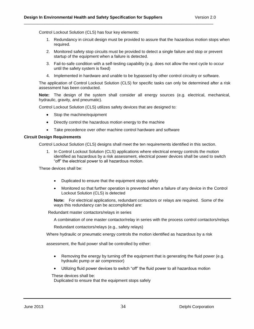
Design In Environmental Health and Safety Specification for Suppliers Version 2.0 __________________________________________________________________________________
June 2013 34 Delphi Corporation
Control Lockout Solution (CLS) has four key elements:
1. Redundancy in circuit design must be provided to assure that the hazardous motion stops when required.
2. Monitored safety stop circuits must be provided to detect a single failure and stop or prevent startup of the equipment when a failure is detected.
3. Fail-to-safe condition with a self-testing capability (e.g. does not allow the next cycle to occur until the safety system is fixed)
4. Implemented in hardware and unable to be bypassed by other control circuitry or software.
The application of Control Lockout Solution (CLS) for specific tasks can only be determined after a risk assessment has been conducted.
Note: The design of the system shall consider all energy sources (e.g. electrical, mechanical, hydraulic, gravity, and pneumatic).
Control Lockout Solution (CLS) utilizes safety devices that are designed to:
Stop the machine/equipment
Directly control the hazardous motion energy to the machine
Take precedence over other machine control hardware and software
Circuit Design Requirements
Control Lockout Solution (CLS) designs shall meet the ten requirements identified in this section.
1. In Control Lockout Solution (CLS) applications where electrical energy controls the motion identified as hazardous by a risk assessment, electrical power devices shall be used to switch “off” the electrical power to all hazardous motion.
These devices shall be:
Duplicated to ensure that the equipment stops safely
Monitored so that further operation is prevented when a failure of any device in the Control Lockout Solution (CLS) is detected
Note: For electrical applications, redundant contactors or relays are required. Some of the ways this redundancy can be accomplished are:
Redundant master contactors/relays in series
A combination of one master contactor/relay in series with the process control contactors/relays
Redundant contactors/relays (e.g., safety relays)
Where hydraulic or pneumatic energy controls the motion identified as hazardous by a risk
assessment, the fluid power shall be controlled by either:
Removing the energy by turning off the equipment that is generating the fluid power (e.g. hydraulic pump or air compressor)
Utilizing fluid power devices to switch “off” the fluid power to all hazardous motion
These devices shall be: Duplicated to ensure that the equipment stops safely

Design In Environmental Health and Safety Specification for Suppliers Version 2.0 __________________________________________________________________________________
June 2013 35 Delphi Corporation
Monitored so that further operation is prevented when a failure of any device in the Control Lockout Solution (CLS) is detected
Note: For pneumatic or hydraulic applications, where the energy is not removed by turning off the equipment generating the fluid power, redundant valves are required. Some of the ways this redundancy can be accomplished are:
Redundant master valves in series
A combination of one master valve in series with the process control valves
Redundant valves (e.g., safety valves)
2. The Control Lockout Solution (CLS) shall be hardware-based. The hardware shall take priority over any software signals used to control the manufacturing process. The Control Lockout Solution (CLS) cannot rely on software-controlled inputs or outputs to safely stop hazardous motion. However, software inputs can be used to monitor the status of the Control Lockout Solution (CLS).
3. Power devices shall be rated for the maximum-switched load available at any time. The control devices that control the primary energy must be sized to handle the maximum-switched load. Power factor, duty cycle, and switch load vs. life should be taken into account when selecting safety components. In an electrical circuit, the protective devices (e.g., fuses or circuit breakers) determine the maximum loads that can exist at any time. In a hydraulic circuit, consult Hydraulic Fluid Power - General Rules Relating to Systems, International Organization for Standardization--ISO 4413 or the applicable standard. In a pneumatic circuit, consult Pneumatic Fluid Power - General Rules Relating to System, International Organization for Standardization--ISO 4414 or the applicable standard.
4. The contacts used in the Control Lockout Solution (CLS) (i.e., hardwired circuits) to monitor power devices shall be positive –opening contacts. They shall be either integral to the device or on a screw-on (not snap-on) contact block. Switches used to monitor valve spool position shall change state each time the valve is operated (i.e., each switch shall cycle on-off-on or cycle off-on-off). If a snap-on block is used, it must be used for a power leg and not the monitoring circuit. Switches monitoring valves must be wired such that they must make and break each cycle. Monitoring each state change will detect if the switch becomes detached from the device it is monitoring.
5. Every start and reset circuit used in the Control Lockout Solution (CLS) shall be designed to prevent tie-down. Push buttons with one Normally Open (NO) and one Normally Closed (NC) contact can be used if they are wired so that the Normally Open (NO) contact must close and Normally Closed (NC) contact must open to obtain reset. Single contact push buttons can be used when wired such that they must be pushed to make contact and released to open the contact before a reset is obtained.
6. All safety status indicators for the Control Lockout Solution (CLS) shall be fail-safe. The Control Lockout Solution (CLS) indicator shall be labeled “Control Lockout Solution (CLS) Active – OK to Enter”. This requirement prevents lamp failure, temporary power loss, cable faults, fuse faults, or other faults in the signaling system from indicating Control Lockout Solution (CLS) is active.
Note: If the indicator is ON, the equipment is under Control Lockout Solution (CLS) control. If the indicator is NOT ON, the equipment is not under Control Lockout Solution (CLS) control.
7. Safety status indicators for Control Lockout Solution (CLS) shall be controlled by hardwired devices (e.g., auxiliary contacts of contactors, safety relays, or valve position sensors). These hardwired devices must take priority over any software driven outputs. Software outputs in series—and overridden by the hardware devices—are acceptable.

Design In Environmental Health and Safety Specification for Suppliers Version 2.0 __________________________________________________________________________________
June 2013 36 Delphi Corporation
Note: The power devices cannot be in two states (i.e., “on” and “off”) at the same time. The “true” status of the power source will be indicated only when all power devices are “off.”
8. Audible start-up signals shall not sound if Control Lockout Solution (CLS) has disabled any equipment. There should be input from Control Lockout Solution (CLS) to the system controller that inhibits any “equipment start” warning signals (e.g., horns) when the circuit has disabled any equipment.
9. The control circuit shall not indicate AUTO if Control Lockout Solution (CLS) has disabled any equipment. If the Control Lockout Solution (CLS) has disabled any equipment, there should be input from Control Lockout Solution (CLS) to the system controller to inhibit AUTO mode.
10. All Control Lockout Solution (CLS) mode control devices shall have the capability to be locked in position or be housed in a lockable enclosure. These mode control devices that disable/enable motion when the gate is open must be able to be locked in position or be located behind a cover that can be locked to prevent access. This requirement will prevent changing the mode (allowing motion) of the equipment until all personnel have removed their locks.
Control Lockout Solution (CLS) Task Placards
A Control Lockout Solution (CLS) task placards shall be posted at each entry gate into the cell or equipment. Each placard has three major sections showing the tasks that can be performed under Control Lockout Solution (CLS), the tasks to be performed under Lockout Energy Control, and the hazards that may be encountered when in the safeguarded area.
Hazardous Energy Control - Part Transfer Systems
Hazardous motion from part transfer and/or conveyance systems (that are an integral part of the work cell) shall be stopped by the energy control system. This requirement ensures that no motion may occur, which could cause injury to anyone servicing part of the production system. Reference Safety Standard for Conveyors and Related Equipment International Organization for Standardization/Technical Report--ISO/TR 8435 – Safety code for belt conveyors.
10.0 Robotic Cell A robotic cell is the safeguarded area defined by safeguarding that surrounds the robot(s), the end-effector(s), and other associated machinery and equipment.
Note: Any robot(s) that is an integral part of a machining cell shall be governed by the requirements for a machining cell as outlined in Section 11, Servo Controlled Equipment and Machining Cells.
Reference the American National Standard for Industrial Robots and Robot Systems -- Safety Requirements, ANSI/RIA R15.06 or Manipulating Industrial Robots – Safety or Manipulating industrial robots – Safety, ISO 10218.
10.1 Safety Design Requirements for Robotic Cells
General Layout Requirements
The layout shall include all facility features and equipment intended in the robotic cell including, but not limited to, the following:
Perimeter guarding,
Cell entrances,
Operating spaces (including path of the end-of-arm tooling and any carried parts and materials),

Design In Environmental Health and Safety Specification for Suppliers Version 2.0 __________________________________________________________________________________
June 2013 37 Delphi Corporation
Restricted spaces at operator load/unload stations (reference Section 8.5),
Auxiliary equipment located within the cell guarding (e.g., weld tip dressers),
Location on the plant floor facility equipment and/or obstructions in the cell (e.g. building columns), and
Tooling and transfer systems.
Potential pinch points shall be identified and eliminated as practicable. If not practicable, appropriate safeguarding or controls shall be implemented as determined by the risk assessment.
A design goal shall be to maximize visibility into the cells. Floor standing cabinets that are 5-feet or greater in height shall be positioned to maximize the view of the cell. Angling the placement of a floor standing cabinet may be an effective method of maximizing visibility.
Hard stops shall be located to limit the robot’s reach to all anticipated operating and maintenance positions. Software stops shall be incorporated to prevent collision with the hard stops.
Refer to Figure 10-1 for robot space definitions.
Figure 10-1: Robot Space Definition
Personnel Access Gate Control
In order to provide safe access to equipment requiring service and to facilitate the use of lockout and/or energy control by Control Lockout Solution (CLS), interlocked entrance gates shall be utilized.
Robot Cell Entrance Gate
In order to provide exclusive control of the robot’s hazardous motion within the cell, the entrance gate area shall be equipped with provisions for lockout or Control Lockout Solution (CLS) energy control. At least one entrance gate shall be provided for a cell. When the robot cell occupies both sides of a line and access across the line is hazardous (as determined by the risk assessment), an entrance gate on each side of the line shall be provided.
Cell Entrance and Exit Procedures for an Interlocked Gate
The typical entrance and restart procedures for robotic cells are as follows:
Maximum Space
Restricted Space
Operating Space

Design In Environmental Health and Safety Specification for Suppliers Version 2.0 __________________________________________________________________________________
June 2013 38 Delphi Corporation
Stop the system at the next logical stopping position of the current cycle by actuating a control device (e.g., end-of-cycle stop pushbutton or HMI input screen).
Follow lockout procedure or Control Lockout Solution (CLS) energy control procedures. Open the interlocked gate and enter the cell. Reference Section 8.3. Safety Interlocks for design requirement.
Note: Entry from one cell into an adjacent cell through a Presence Sensing Device (PSD) is not a normal entrance and violates lockout or Control Lockout Solution (CLS) energy control procedures.
In order to reactivate automatic operation, the following actions shall occur within normal start-up procedures:
- Removal of all service equipment and tools,
- Notification of affected and authorized personnel,
- Closure of all gates,
- Resetting of the gate interlock circuits,
- Restoration of all the other safeguards required for automatic operations, and
- Deliberate cell restart action
10.2 Outside and Inside Cell Safeguarding
Outside the Cell Safeguarding
Hard guarding (e.g., fences, gates, walls, and doors) and presence sensing devices (PSD) guarding are approved methods for cell perimeter guarding (Reference Section 8.2 Perimeter Guarding).
Perimeter hard guarding shall be located at a minimum of 15cm (6 in.) outside of the robot’s operating space and shall provide safeguarding from exposure to any hazard inside the cell (including a reach-in hazard) provided that the robot has the following design-in features or equivalent features due to new technology:
Collision detection,
Axes limits,
Over-current protection, and
Following error monitoring.
If the above requirements cannot be met, then alternative safeguarding shall be determined by the risk assessment.
Presence Sensing Device (PSD) perimeter guarding shall meet the requirements of Section 8.3. Presence Sensing Devices (PSD).
Inside the Cell Safeguarding
If a person is not required to be inside the safeguarded area to teach a robot or perform Attended Program Verification (APV), then no additional safeguarding is required other than the cell perimeter guarding. However, this requires that the gate interlock(s) prevent all hazardous robot motion when any personnel access gate is open.

Design In Environmental Health and Safety Specification for Suppliers Version 2.0 __________________________________________________________________________________
June 2013 39 Delphi Corporation
If a person needs to be inside the safeguarding area to teach a robot or perform Attended Program Verification (APV), the potential pinch point hazard between the robot and no-process related obstructions:
Teach and Slow-Speed Attended Program Verification (APV) Operations
Teach and slow-speed Attended Program Verification (APV) is defined as the robot speed limited to 250 mm/sec (10 in./sec). Each person shall have a single point of control (e.g., teach pendant) that is capable of stopping all robot hazardous motions. An SOP may be required as
determined by the risk assessment. Reference Section 10.6 Robot Teach, Slow- and High-Speed APV.
High-Speed Attended Program Verification (APV) Operations
High-speed Attended Program Verification (APV) is defined as the robot speed greater than 25 cm/sec (10 in./sec)
For high-speed Attended Program Verification (APV) tasks, only one person shall be allowed in a cell at any one time. This person shall have a single point of control (e.g., teach pendant) that is capable of stopping all hazardous motion within the cell. An Safe Operation Procedure (SOP) shall be provided to identify the safe positions(s) to stand within the cell for these types of tasks. Reference Section 10.6, Robot Teach, Slow- and High-Speed APV.
10.3 Shared Workspace Safeguarding
A shared workspace is the space or work area that the robot reaches during normal automatic operation. It is also the space or work area that, at a different time, an individual has to access as part of the normal production operation.
Presence Sensing Devices
When loading and unloading operation cannot be designed to completely remove the operator from the shared workspace, this space or work area shall be safeguarded to prevent a robot and person occupying the same space simultaneously. Typically a Presence Sensing Devices (PSD) is used to safeguard the operator; however, moveable interlock barrier guards can also be used.
The Presence Sensing Devices (PSD) shall be positioned to meet the following requirements:
The robot-restricted space shall not extend beyond the operator Presence Sensing Devices (PSD).
The location of the Presence Sensing Devices (PSD) shall comply with the safe distance formula (reference Annex A) to the nearest point-of-operation hazard for the operator implemented consistent with the risk assessment.
When a worker is present (the operator Presence Sensing Devices (PSD) is tripped/interrupted), the robot end-of-arm tooling and/or the part being carried shall be prevented from entering the shared workspace. Other associated hazardous motion (e.g., tool clamps, weld guns) shall be controlled and/or abated. One of the following methods shall be used (based on the risk assessment):
A Presence Sensing Devices (PSD) for detecting the position of the robot shall stop the robot from entering the shared workspace when a person is in the shared workspace.
Switches or sensors that detect robot position shall be implemented to comply with the control reliable (reference Section 8.7) design and shall stop the robot from entering the shared workspace.
The operator Presence Sensing Devices (PSD) may be muted by a hardware-based, control reliable safety circuit when another safeguarding device (e.g., robot Presence Sensing Devices (PSD)) indicates there is no hazard from the robot. This circuit allows the operator to reach inside the workspace when the robot is in a safe position within the robot cycle. If the robot approaches the shared workspace

Design In Environmental Health and Safety Specification for Suppliers Version 2.0 __________________________________________________________________________________
June 2013 40 Delphi Corporation
while the operator is present or the operator attempts to enter the shared workspace (envelope) when the robot is present, the robot shall stop immediately. During the machine cycle, an indicator (e.g., green status light) that is visible from the operator’s workstation shall indicate the point in the process cycle when the operator can reach into the shared workspace without stopping the process.
The location of the safeguarding devices on the robot side of the shared workspace shall be installed in a manner that stops the robot before any part of its tooling or the part being carried enters into the shared workspace.
Limiting Devices
Limiting devices that establish the restricted space for a robot shall be used as defined below.
10.4 Mechanical and Non-mechanical Limiting Devices
The robot-restricted space is defined based on the placement of the mechanical (e.g., hard stops) and /or non-mechanical (e.g., Presence Sensing Devices (PSD)) limiting devices. Building columns and other physical barriers (e.g., equipment, tooling) may also define the restricted space, per the risk assessment. The cell designs shall allow the operator to remain safe after the cycle start device has been activated. The non-mechanical limiting devices shall be implemented as specified by the risk assessment circuit performance.
10.5 Robot Restricted Space and Dynamic Limiting Devices (DLD)
Through the use of Dynamic Limiting Devices (DLDs), the robot’s restricted space can be automatically changed during a portion of the robot’s cycle to allow manual loading/unloading tasks performed while the robot is clear from the operators work area. Control devices such as, but not limited to, cam operated limit switches or light curtains may be utilized to limit robot movement when the operator is interrupting the operator Presence Sensing Devices (PSD) while the robot performs its task program. The device(s) shall be positioned so that the robot stops before entering the shared workspace. Dynamic Limiting Devices (DLDs) shall be integrated as specified by the risk assessment circuit performance. The Dynamic Limiting Devices (DLD) shall not be used as the operator Presence Sensing Devices (PSD). See the example in Figure 10-2.
Figure 10-2: Operator Loading/Unloading Task
When teaching the robot, the operator Presence Sensing Devices (PSD) and/or Dynamic Limiting Devices (DLDs) may be bypassed in a control reliable manner to allow the teacher to stand close to the equipment or tooling to perform the task.
Restricted Space
Light curtain used as limiting device to reduce restricted space (Dynamic Limiting Devices)
Dual cam dual base switches mute the operator-side Presence Sensing Devices (PSDs) when the robot is away
Modified restricted space
including over-travel
Point of operation light curtains

Design In Environmental Health and Safety Specification for Suppliers Version 2.0 __________________________________________________________________________________
June 2013 41 Delphi Corporation
10.6 Robot Cell Requirements
Robot Teach, Slow- and High-Speed Attended Program Verification (APV)
All cell control systems shall be designed to provide each person in the cell with the capability to stop hazardous motion while motion power is available. This requirement can be met through the use of a robot teach pendant or an enabling device.
A method shall be provided to limit the speed of the robot to a maximum of 25 cm/sec (10 in./sec) when in teach mode, slow-speed Attended Program Verification (APV) with a person inside the cell.
A design goal shall be to eliminate the need of high-speed Attended Program Verification (APV) with a person inside the cell.
Note: The need for high-speed Attended Program Verification (APV) with a person inside the cell may be eliminated by: (1) equipment/process selection, (2) locating the process requiring high-speed Attended Program Verification (APV) to be visible outside the cell, or (3) eliminating the ability of high-speed Attended Program Verification (APV) to run with any personnel access gate safety interlock open.
However, if high-speed Attended Program Verification (APV) is required the following items shall be made available prior to its initial use on any given system:
Layout showing the robot’s restricted and operating spaces,
Risk assessment covering the high-speed Attended Program Verification (APV) tasks and associated hazards, and
Safe Operating Procedures (SOPs) for the high-speed Attended Program Verification (APV) task.
The Safe Operating Procedure (SOP) should include a requirement to run the path at slow speed before enabling high speed and identify safe teacher positions for high-speed Attended Program Verification (APV).
Material Handling Applications
For a gravity hazard concern, a material handling robot shall retain the material in its end-effector in the event of a loss of energy to the robot servos. For a vacuum cup application, end-effector part retention (e.g., a vacuum lock) shall be provided when personnel enter the safeguarded area. The plan shall have an ongoing maintenance procedure in place for end-effector tooling.
Material handling robotic cells shall utilize perimeter hard guarding when material ejection poses a hazard (reference Section 8.2 Perimeter Hard Guarding)
11.0 Servo Controlled Equipment and Machining Cells
This section lists the specific safety requirements for individual Servo Controlled Equipment and also machining cells. Servo Controlled Equipment is any machine that utilizes servo systems for machine motion. This would include multi-axis assembly machines and individual Computer Numerically Controlled (CNC) metal removing equipment. Individual Computer Numerically Controlled (CNC) metal removing equipment include machine tools in which the principle movement is the rotation of the work piece against a stationary tool (i.e. lathe) or a machine tool in which the principle movement is a rotating tool against a stationary work piece (i.e. machining center). In both cases, the machine operates under computer numerical control. A machining cell is a cell/system that incorporates industrial machinery and related devices and equipment. This related equipment is linked by material handling devices and operated by programmable electronic systems. These electronic systems are capable of being reprogrammed for the manufacturing of discrete parts or assemblies. The applications within the cell may include manual or automatic drilling, milling, boring, turning, grinding, etc. as well as limited subassembly operations.

Design In Environmental Health and Safety Specification for Suppliers Version 2.0 __________________________________________________________________________________
June 2013 42 Delphi Corporation
Reference: Manufacturing Systems/Cells-Safety Requirements for Construction, Care and Use, American National Standards Institute--ANSI B11.20.
This section is divided into safety design requirements for individual servo controlled equipment and then machining cells.
11.1 Safety Design Requirements for Individual Servo Controlled Equipment
This section discusses the General Requirements for Servo Controlled Equipment safety and then discusses safety issues related to the operator and maintenance personnel.
General Safety Requirements for Servo Controlled Equipment
All servo-controlled machines shall be designed so that loss of electrical power or voltage surges or changes in oil/air pressure will not result in a hazard.
A means for isolating any electrical, mechanical, hydraulic, or pneumatic energy source and any stored energy associated with the servo controlled equipment shall be provided in accordance with Section 9, Energy Control and Lockout, of this document. Access to any energy isolating device must not be inhibited by other hardware associated with the servo controlled equipment (e.g. electrical panel mounted directly above a self-contained coolant system) or means shall be provided to gain access to the energy isolating device (i.e. a movable platform rolled into place over coolant system in previous example).
Actuating controls that initiate motion shall be located to prevent inadvertent operation (i.e. guarded pushbutton or two-hand control). In addition, controls and equipment requiring access during automatic operation of the servo-controlled equipment shall be located outside the safeguarded area in accordance with Section 8.3, Safeguarding Devices, of this document.
All safeguarding devices utilized for protection against the hazards associated with the operation and maintenance of servo controlled equipment shall be applied as specified by the risk assessment circuit performance in accordance with Circuit Performance Area of this document. Additional information in regards to methods of selecting and implementing appropriate safeguarding can be found in Section 8, Safeguarding, of this document. It should be noted that safeguarding devices are installed only after all opportunities for designing out the hazard have been effectively considered and/or eliminated.
All operator/maintenance stations, including remote pendant enabling devices, on servo controlled equipment shall have Emergency Stop devices installed in accordance with Section 8.5, Emergency Stop Function and Devices, of this document. These E-stop devices shall cause all moving parts of the machine to stop and remove all drive power from the servo drives.
Software and firmware based controllers used in place of hardware based components with safety-related devices shall require approval by the Delphi Electrical Controls Engineer and must meet the following requirements:
o Be designed such that any single safety related component or firmware failure shall:
Lead to the shutdown of the system in a safe state, and
Prevent subsequent automatic operation until the component failure has been corrected.
Supply the same degree of safety achieved by using hardwired/hardware components per Circuit Performance Area For example, this degree of safety may be achieved by using microprocessor redundancy and self-checking.
Electrical connectors that could cause a hazard if they are separated, or if they break away, shall be designed and constructed as to guard against such unintended separation.

Design In Environmental Health and Safety Specification for Suppliers Version 2.0 __________________________________________________________________________________
June 2013 43 Delphi Corporation
11.2 Operator Safety Requirements for Servo Controlled Equipment
Operator Workstation Interface
Load/Unload Devices. When selecting the interface between an operator and automatic equipment, operator safety and ease of use are primary concerns. Throughput, station area, equipment complexity, and maintenance requirements are additional concerns. All these factors must be part of the design. Turntables, shuttles, and other load/unload mechanisms implemented as work piece transfer devices that completely remove the operator from the servo controlled equipment hazards should be considered when designing operator load/unload stations. However, turntables, shuttles, etc. may present additional hazards and require special safeguarding (i.e. two hand control), refer to Section 8, Safeguarding, of this document for Safeguarding Options. All safeguarding for work piece transfer devices shall be implemented as specified by the risk assessment circuit performance in accordance with Circuit Performance Area of this document. Where access is required to the work piece transfer device with the guards open, the safeguard devices suspended, and powered motion is necessary for adjustment or maintenance, such motion shall be initiated with a hold-to-run device as a function of the main operator console or remote pendant enabling device as described in Section 11.3 below.
Presence Sensing Devices (PSDs). When the loading and unloading operations cannot be designed to completely remove the operator from the servo controlled equipment hazard, the shared workspace on the operator’s side shall be protected by a Presence Sensing Devices (PSD) (refer to Section 8.3 PSD) of this document) or movable interlocked barrier guard. The intent of utilizing Presence Sensing Devices (PSDs) or a movable interlocked barrier guard is to prevent any motion of the servo controlled machine while the operator is loading/unloading the machine. Both the Presence Sensing Device (PSD) and movable interlocked barrier guard shall be implemented as specified by the risk assessment circuit performance in accordance with Circuit Performance Area of this document.
Automatic Tool Changers. When the servo controlled equipment is equipped with an automatic tool changer, access to hazardous movements of the tool changer shall be prevented by fixed and interlocked movable guards implemented as specified by the risk assessment circuit performance in accordance with Circuit Performance Area of this document. When the interlocked movable guard is open, the tool magazine drive power shall be positively disconnected by means of a category 1 stop (see 9.5.2 of National Fire Protection Association NFPA 79). Means shall be provided to allow viewing of the movement of the tool changer while the guard is closed.
11.3 Maintenance Personnel Safety Requirements for Servo Controlled Equipment
Most maintenance activities for servo controlled equipment shall be done with energy sources powered down and lockouts applied in accordance with Section 9, Energy Control and Lockout, of this document. However, certain tasks (i.e. spindle alignment, tool changer alignment, clearing part jams, qualifying fixtures, etc.) may require power to remain in an energized state to perform the task. The maintenance person must have single point of control of the servo-controlled equipment in order to perform these tasks with drive power enabled. Single point of control shall include:
Provisions to move a single axis at a time and at a reduced speed not to exceed 2 meters/minute.
Providing a hold-to-run device which when held in an actuated position shall allow motion to occur and also disable motion when released.
Disabling Automatic Operation of the servo controlled equipment when single point of control activated.
Two options are available for providing single point of control. These options are:

Design In Environmental Health and Safety Specification for Suppliers Version 2.0 __________________________________________________________________________________
June 2013 44 Delphi Corporation
If the maintenance person can safely and effectively perform the required maintenance task with drive power enabled while standing on the floor at the main operator’s station, then controls can be provided in the main operators console for satisfying single point of control items listed above.
If the maintenance person cannot safely and effectively perform the required maintenance task with drive power enabled while standing on the floor at the main operator’s station, then a remote pendant enabling device shall be installed on the machine to provide single point of control. The remote pendant enabling device shall include controls for all items listed above for single point of control and shall incorporate these additional features:
- Physically disable the main operator’s console when the remote pendant enabling device is actuated. This disabling of the main operators console shall be accomplished via hardwiring and not through simple software techniques.
- An Emergency Stop device implemented in accordance with Section 8.5, Emergency Stop Function and Devices, of this document.
- The remote pendant enabling device shall be implemented as specified by the risk assessment circuit performance in accordance with Circuit Performance Area of this document.
11.4 Safety Design Requirements for Machining Cells
The specific machining cell design-in requirements are listed in the following sections.
Process Layout Analysis
Placement of the guarding, cell entrances and limiting devices shall be established during the pre-tool design phase.
The process layout shall include all facility features and equipment that are intended to be included in the machining cell. This process analysis shall be performed by a Delphi representative and, if applicable, by the machine tool builder/integrator.
This layout shall include, but not be limited to, the following features:
Guarding that includes the perimeter
Cell entrances that lead into hazardous zones
Hazardous zones
Location of all energy control devices
Auxiliary equipment (e.g., measurement/gauging systems, transfer systems)
Process equipment
Presence Sensing Devices (PSDs)
Actual location on the floor
Tooling access points
Locations of both the operator and maintenance tasks
Material stock bins/containers
Electrical disconnects shall be placed in a manner that provides an adequate amount of space to stand to the side of the electrical enclosure.
Note: When multi-axis machines are utilized in the process, simulation may be necessary to adequately design a safe system as determined by manufacturing/process engineering.

Design In Environmental Health and Safety Specification for Suppliers Version 2.0 __________________________________________________________________________________
June 2013 45 Delphi Corporation
A hardcopy of the completed process layout analysis shall be available for use during the risk assessment process.
Entrance Gate Safety Interlocking
The following entrance gate safety-interlocking approach for machining cells shall serve as the preferred method of interlocking.
In addition to meeting the requirements of Section 8.3 Safety Interlocks, the entrance gate shall be designed as follows:
Normal entrance into a cell shall require operator selection of the manual mode or the system to reach the end of its cycle.
The interlock shall prevent the gate from opening until all hazardous motion has stopped.
Inadvertent access into the cell shall be prevented by a solenoid switch that locks all the gates while in automatic mode or during a “power off” condition.
Reactivating the automatic operation requires the following start-up procedures:
- Closure of all the gates
- Resetting the gate interlock circuits
- Restoration of all the other safeguards
- Deliberate cell restart action
Robots Within Machining Cells
When robots are used within a machining cell, risk assessment shall be performed on the cell to determine which requirements shall be applied from Section 10, Robotic Cell, of this specification.
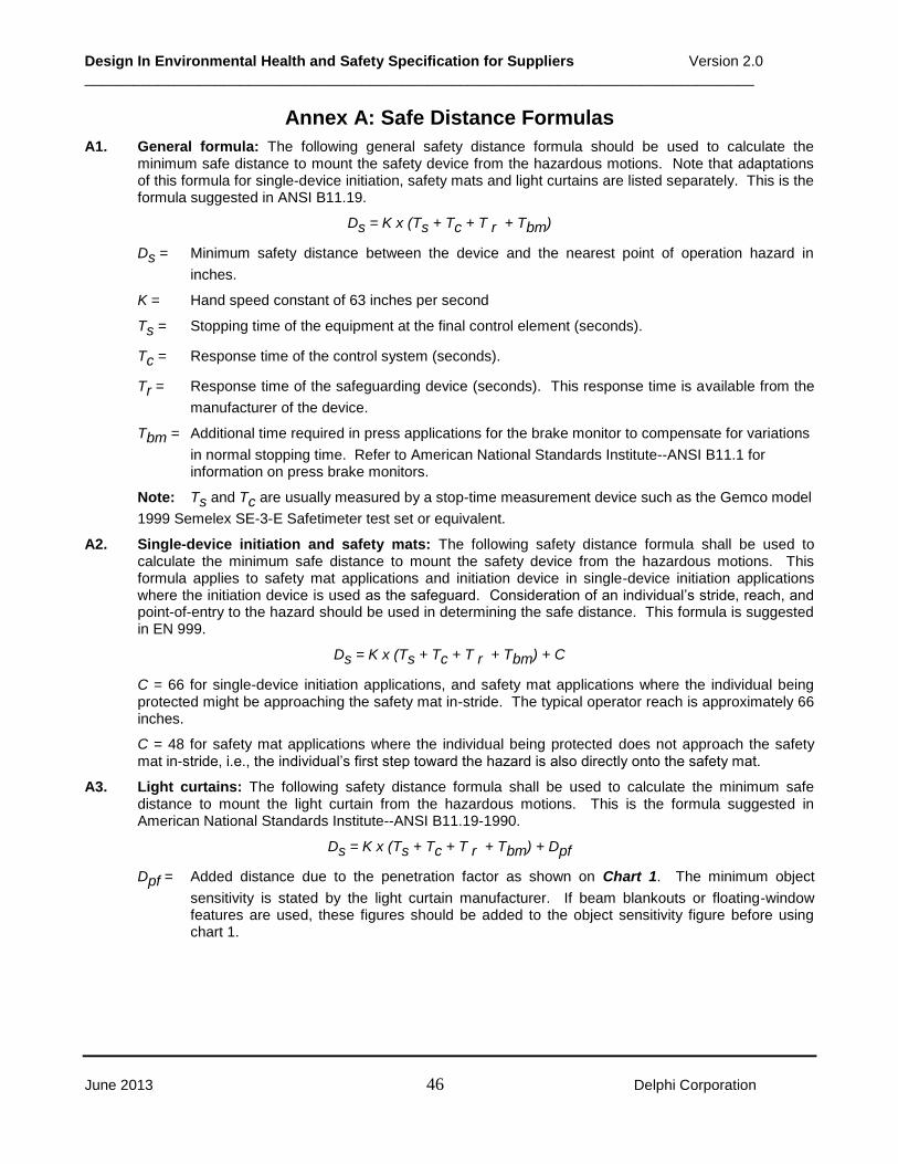
Design In Environmental Health and Safety Specification for Suppliers Version 2.0 __________________________________________________________________________________
June 2013 46 Delphi Corporation
Annex A: Safe Distance Formulas
A1. General formula: The following general safety distance formula should be used to calculate the minimum safe distance to mount the safety device from the hazardous motions. Note that adaptations of this formula for single-device initiation, safety mats and light curtains are listed separately. This is the formula suggested in ANSI B11.19.
Ds = K x (Ts + Tc + T r + Tbm)
Ds = Minimum safety distance between the device and the nearest point of operation hazard in
inches.
K = Hand speed constant of 63 inches per second
Ts = Stopping time of the equipment at the final control element (seconds).
Tc = Response time of the control system (seconds).
Tr = Response time of the safeguarding device (seconds). This response time is available from the
manufacturer of the device.
Tbm = Additional time required in press applications for the brake monitor to compensate for variations
in normal stopping time. Refer to American National Standards Institute--ANSI B11.1 for information on press brake monitors.
Note: Ts and Tc are usually measured by a stop-time measurement device such as the Gemco model
1999 Semelex SE-3-E Safetimeter test set or equivalent.
A2. Single-device initiation and safety mats: The following safety distance formula shall be used to calculate the minimum safe distance to mount the safety device from the hazardous motions. This formula applies to safety mat applications and initiation device in single-device initiation applications where the initiation device is used as the safeguard. Consideration of an individual’s stride, reach, and point-of-entry to the hazard should be used in determining the safe distance. This formula is suggested in EN 999.
Ds = K x (Ts + Tc + T r + Tbm) + C
C = 66 for single-device initiation applications, and safety mat applications where the individual being protected might be approaching the safety mat in-stride. The typical operator reach is approximately 66 inches.
C = 48 for safety mat applications where the individual being protected does not approach the safety mat in-stride, i.e., the individual’s first step toward the hazard is also directly onto the safety mat.
A3. Light curtains: The following safety distance formula shall be used to calculate the minimum safe distance to mount the light curtain from the hazardous motions. This is the formula suggested in American National Standards Institute--ANSI B11.19-1990.
Ds = K x (Ts + Tc + T r + Tbm) + Dpf
Dpf = Added distance due to the penetration factor as shown on Chart 1. The minimum object
sensitivity is stated by the light curtain manufacturer. If beam blankouts or floating-window features are used, these figures should be added to the object sensitivity figure before using chart 1.

Design In Environmental Health and Safety Specification for Suppliers Version 2.0 __________________________________________________________________________________
June 2013 47 Delphi Corporation
CHART 1
2.5
2.0
1.5
1.0
0.5
0.0
0.0 1.0 2.0 3.0 4.0 5.0 6.0 7.0 8.0
PENETRATION FACTOR Dpf IN INCHES
BLANKED DIMENSIONS
OR MINIMUM OBJECT
SENSITIVITY IN INCHES


