Design in Brickwork Non Load Bearing
4
5/14/13 Design in Brickwork faculty.arch.usyd.edu.au/pcbw /w alls/non-loadbearing/index .html 1/4 Introduction Brickwork Design Walls Loadbearing Non-Loadbearing Lintels & Openings Reinforced Brickwork Brick Rod Mortar & Joints Control Joints Weather Resistan ce Thermal Performance Acoustic & Fire Case Studies Bibliography Appendices Non-Loadbearing Walls Why non-loadbearing walls The base of the walls in large nineteenth-century buildings were quite thick (up to a metre or more), because of the heavy loads to be carried and, before the use of cement mortar, the low strength of the joints. Modern masonry walls can be made to carry considerable loads by the use of high-strength bricks and mortar, but often a framed structure allows more freedom in the design of the facade as well as in the pl ann i ng of th e i nt erior. A s tructural fram e of reinforced concrete or steel can support the loads of the floors and roof, and al so of the non-loadbearing wa lls. The external walls then perform all the 'enclosure' f u nctions. Each wall panel also carries its own weight and resists wind and seismic loads, but only those that act on the panel itself. These images of the loadbearing Monadnock Building and the framed Reliance bui l din g (both Bu rn ham and Root, Architects, Chicago 1890) illustrate some of the freedom that a fram e allows on the facade. Monadnock building, Chicago Reliance building, Chicago Arrangement of supports There is a choice to be made about the appearance of a non-loadbearing external wall. It may completely enclose the structure, or expose the columns, or the floors, or both. Each of these alternatives will require different details in plan and in section.
Transcript of Design in Brickwork Non Load Bearing

7/30/2019 Design in Brickwork Non Load Bearing
http://slidepdf.com/reader/full/design-in-brickwork-non-load-bearing 1/4
5/14/13 Design in Brickwork
faculty.arch.usyd.edu.au/pcbw/walls/non-loadbearing/index.html 1/4
Introduction
Brickwork Design
Walls
Loadbearing
Non-Loadbearing
Lintels & Openings
Reinforced Brickwork
Brick Rod
Mortar & Joints Control Joints
Weather Resistance
Thermal Performance
Acoustic & Fire
Case Studies
Bibliography
Appendices
Non-Loadbearing Walls
Why non-loadbearing walls
The base of the walls in large nineteenth-century buildings were quite thick (up to a
metre or more), because of the heavy loads to be carried and, before the use of cement mortar, the low strength of the joints. Modern masonry walls can be made to
carry considerable loads by the use of high-strength bricks and mortar, but often a
framed structure allows more freedom in the design of the facade as well as in the
planning of the interior.
A structural frame of reinforced concrete or steel can support the loads of the floors
and roof, and also of the non-loadbearing walls. The external walls then perform all
the 'enclosure' f unctions. Each wall panel also carries its own weight and resists wind
and seismic loads, but only those that act on the panel itself.
These images of the loadbearing Monadnock Building and the framed Reliance building (both Burnham and Root, Architects, Chicago 1890) illustrate some of the
freedom that a frame allows on the facade.
Monadnock building, Chicago
Reliance building, Chicago
Arrangement of supports
There is a choice to be made about the appearance of a non-loadbearing external
wall. It may completely enclose the structure, or expose the columns, or the floors,
or both. Each of these alternatives will require different details in plan and in section.
7/30/2019 Design in Brickwork Non Load Bearing
http://slidepdf.com/reader/full/design-in-brickwork-non-load-bearing 2/4
5/14/13 Design in Brickwork
faculty.arch.usyd.edu.au/pcbw/walls/non-loadbearing/index.html 2/4
It is usual, but not always necessary, to support the wall at each floor level. By
exposing every second floor slab, a different scale and proportion can be achieved in
the elevation.
The method of supporting the external leaf on the floors depends on whether the
edge of the floor is exposed or not.
The wall can sit on top of the floor slab.
The full depth of the slab (and beam, if any) is exposed. This detail should preferably
be modified with a recess in the edge of the slab, so that any water penetrating under
the flashing does not enter the building, in the same way that the edge of a domestic
raft slab is recessed. If there is no recess (especially when the wall sits on a slab
which is too thin to accommodate a recess), then the flashing can be turned down at
the outer edge of the beam.
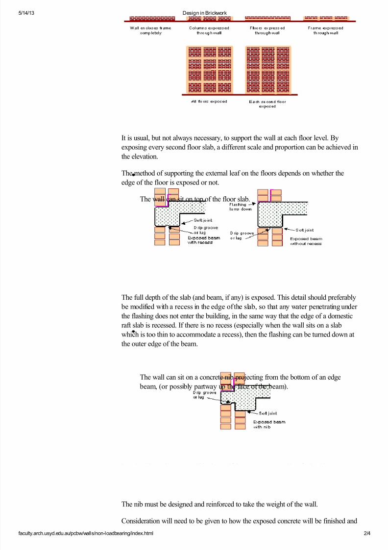
The wall can sit on a concrete nib projecting from the bottom of an edge
beam, (or possibly partway up the face of the beam).
The nib must be designed and reinforced to take the weight of the wall.
Consideration will need to be given to how the exposed concrete will be finished and

7/30/2019 Design in Brickwork Non Load Bearing
http://slidepdf.com/reader/full/design-in-brickwork-non-load-bearing 3/4
5/14/13 Design in Brickwork
faculty.arch.usyd.edu.au/pcbw/walls/non-loadbearing/index.html 3/4
how it will weather. It would be better if the concrete was either flush with, or set
back from, the face of the brickwork. To prevent water from tracking in on the
underside of the beam, either a drip groove is formed in the concrete, or a drip angle
is fixed with a mastic seal to the underside at the cavity location. Where an opening
occurs directly under the beam, a similar drip groove or lug is needed to minimise
staining from dirt laden water flowing from the brick surface above.
The wall can be supported on a shelf angle, at the bottom or any other
position on the face of the slab or edge beam.
This provides a continuous brick facade without showing the slab. The angle is of
either galvanised or stainless steel.
Note: The flashings shown in these illustrations are further discussed inFlashings at
floor level.
Some textbooks show thin pieces of brick, known as "brick slips" or "biscuits", as afacing to allow both leaves to be supported on the slab without showing concrete on
the face. This detail is not recommended, as there is a danger of the small pieces
being dislodged due to loading or differential movement. The outer leaf is also likely
to be supported eccentrically, to a greater extent than with a shelf angle.
Stability of non-loadbearing walls
The additional load imposed on loadbearing walls helps to prevent tension
developing, and therefore helps to prevent overturning. In addition, the fact that all
the walls are connected together at each floor level, and at the roof, helps to make
them all act together to support each other. Non-loadbearing walls lack these
benefits.
When a brick wall is supported on a concrete beam or a shelf angle at each floor

7/30/2019 Design in Brickwork Non Load Bearing
http://slidepdf.com/reader/full/design-in-brickwork-non-load-bearing 4/4
5/14/13 Design in Brickwork
faculty.arch.usyd.edu.au/pcbw/walls/non-loadbearing/index.html 4/4
eve , care mus e a en a e ower wa oes no acc en a y p c up oa rom
the floor above. A "soft joint" (a joint filled with compressible material and sealed
with mastic) is used at the top of each wall. (See Horizontal Soft Joints.) This not
only prevents the transfer of vertical loads, but it also removes the restraining effect
of the upper floor. The wall panel is virtually freestanding from its base.
If the wall is built as an infill between columns, it also loses support at the sides of the
columns.
To overcome these problems, a variety of special ties have been developed. They
are all based on the principle of allowing movement in one direction but restraining it
in the other directions, basically by sliding one flattened tube inside a larger one. (See
Wall Anchors under Lintels and Openings.) A cavity wall in this situation has the
advantage of greater stiffness than a single-leaf wall, but nevertheless usually requires
support back to the structural frame. Reinforcing the brickwork may also provide
additional support.
Brick veneer walls
An external brick wall provides all the advantages of appearance and durability,
whether it is a full cavity wall or a brick veneer over a framed internal leaf. In
commercial buildings, it is common to use plasterboard on steel studs for the internal
walls, and brickwork for the external leaf of the perimeter walls. In this case, the
brickwork is stabilised by means of wall ties to the steel studs.
A brick veneer wall also allows the inclusion of thermal insulation between the studs,
which is easier than insulating a cavity brick wall. The durability of the internal walls
may be less than if they were all of brickwork.
Return To Top Next section: Lintels and Openings