Design, Implementation, and Practical Experience of an ...
10
Design, Implementation, and Practical Experience of an Emergency Control System for the Country of Georgia Power System Alexander Didbaridze and Siegmar Leutloff JSC Georgian State Electrosystem Diego Rodas and Fernando Calero Schweitzer Engineering Laboratories, Inc. Presented at the DistribuTECH Conference San Diego, California January 29–31, 2013 Previously presented at the 3rd Annual Protection, Automation and Control World Conference, June 2012 Originally presented at the 14th Annual Western Power Delivery Automation Conference, March 2012
Transcript of Design, Implementation, and Practical Experience of an ...

Design, Implementation, and Practical Experience of an Emergency Control System
for the Country of Georgia Power System
Alexander Didbaridze and Siegmar Leutloff JSC Georgian State Electrosystem
Diego Rodas and Fernando Calero Schweitzer Engineering Laboratories, Inc.
Presented at the DistribuTECH Conference
San Diego, California January 29–31, 2013
Previously presented at the 3rd Annual Protection, Automation and Control World Conference, June 2012
Originally presented at the 14th Annual Western Power Delivery Automation Conference, March 2012

1
Design, Implementation, and Practical Experience of an Emergency Control System
for the Country of Georgia Power System
Alexander Didbaridze and Siegmar Leutloff, JSC Georgian State Electrosystem Diego Rodas and Fernando Calero, Schweitzer Engineering Laboratories, Inc.
Abstract—The country of Georgia power system is subject to severe instability when any of the 500 kV lines are lost due to power system faults and/or accidental disconnections. Two islands are formed, requiring load shedding in the load center and generation shedding in an important power center of the system. The amount of power shedding is determined by the load served by the 500 kV system prior to the opening of the line terminals. An emergency control system (ECS) was proposed by Georgian State Electrosystem to quickly and safely balance generation and load during a system event. The ECS was implemented with customized logic, off-the-shelf protection, control, and monitoring devices, and high-speed IEC 61850 Generic Object-Oriented Substation Event (GOOSE) messages. Human-machine interfaces (HMIs) are used by operators for system control, monitoring, and management of the power threshold settings. In the months following the successful installation and commissioning, the ECS successfully prevented power system total blackouts five separate times in two weeks during the summer when the power consumption reached peak load.
This paper first presents the challenges in the existing power system and the requirements for the ECS. Then the ECS solution design and communications network are described. The system communicates over a dedicated Ethernet network, allowing the use of IEC 61850 GOOSE control messages, as well as engineering access with the remote devices via Telnet and File Transfer Protocol (FTP). The implemented ECS logic is discussed in detail, as well as the timing required to meet the specifications. The experience of commissioning the system and testing it with in-service devices in a staged country-wide blackout is described. The unique ECS functionality of providing Global Positioning System-synchronized (GPS-synchronized) events allows the verification of the logic and its functionality with a number of real events that were experienced by the power system immediately after the ECS commissioning. The oscillography allowed Georgian State Electrosystem to verify and tune the power thresholds used.
I. INTRODUCTION
The country of Georgia is located east of the Black Sea with boundaries with Russia to the north, Turkey to the southwest, Armenia to the south, and Azerbaijan to the southeast. Most of the electrical load is consumed at the capital city Tbilisi, located in the southeast of the country. To the west of the country, an important hydroelectric plant in Enguri generates the majority of the power to be transmitted to Tbilisi. There are links to the neighboring countries, but at the
present time, these links do not influence the stability concerns of the power system.
Fig. 1 shows the Georgian major transmission lines and substations. Georgian State Electrosystem ensures electric power transmission over the entire territory of Georgia. Georgian State Electrosystem is responsible for operations, management, and dispatching within the Georgian power system and has responsibility for the operation of the 500 kV, 220 kV, 110 kV, and 35 kV transmission facilities while maintaining power system stability. The system comprises 3,000 kilometers of transmission lines (500 kV, 220 kV, 110 kV, and 35 kV) and 89 substations dispersed in the Georgian territory.
The Enguri power plant in the Imereti power plant region, identified by a pointing arrow in Fig. 1, generates the power that is delivered to the Tbilisi load region via the 500 kV Imereti and Kartli 2 lines. The flow in the 220 kV system to the Tbilisi region is considered secondary compared with the 500 kV backbone.
If either the Imereti or the Kartli 2 line is lost, the power system can be effectively divided into two electrical islands (considering the 500 kV system only), and as a consequence, the 220 kV system can be overloaded. The Tbilisi load region will lack generation, and the Enguri power plant region will have a power surplus; therefore, the two electrical islands will be unstable. In the Tbilisi load region, loads should be shed to mitigate the generation deficit. At the Enguri power plant, the excess generation needs to be reduced by shedding the appropriate number of generators.
In the summer of 2010, the scenario described in the previous paragraph occurred several times, leading to a blackout of a large percentage of the power system. Traditional underfrequency schemes are too slow to guarantee the stability of the system under these circumstances. The average recovery time for these incidents was more than 1 hour.
Occurrences of instability and long recovery times from blackouts are not acceptable in modern power systems. Georgian State Electrosystem therefore proposed a wide-area protection scheme, referred to as an emergency control system (ECS), to provide fast-acting stability control of the power system.

2
Fig. 1. The Georgian Power System
II. EMERGENCY CONTROL SYSTEM DESCRIPTION
The ECS requirements were defined by system studies performed at Georgian State Electrosystem. Based on the experience of several blackouts during the summer of 2010, the system needed to be in service before the summer of 2011. Simplicity of design and field implementation was necessary in order to simplify deployment.
Based on stability studies and considerations, the ECS is required to operate by shedding appropriate loads and generation at Enguri in less than 100 milliseconds, excluding breaker operation time. The load and generation shedding need to consider the power flow at the time of the loss of the 500 kV line and compare it with three predetermined thresholds linked to the amount of load and generation to be shed.
A. Contingency Recognition
The loss of either the 500 kV Imereti or Kartli 2 transmission line and the overload of the 220 kV circuit can effectively split the power system in two. The system must therefore quickly and reliably recognize the opening of breakers associated with these transmission lines. The lines are subject to frequent transmission line faults during the summer, and the line protection systems clear the faults by opening the breakers.
Single-pole tripping relays and breakers are used, but the opening of a single pole of the breaker is not a contingency. However, for multiphase and permanent faults, the protective relays open the three phases of the breakers. This is recognized as a contingency.

3
Fig. 2 is a simplified diagram of the power system shown in Fig. 1. The Imereti line loss is detected at the Zestaponi substation. The Kartli 2 line loss is detected at the Ksani substation.
Fig. 2. Simplified Georgian Power System
At both the Zestaponi and Ksani substations, the power flow is constantly monitored and remembered to provide pre-event measurements in the event of line loss. These measurements are used for calculating the load-shedding signals sent to seven substations in the Tbilisi region. The severity of the load shedding is based on the comparison of the measured power flow with three defined power thresholds. These three severity levels are used to decide which loads to disconnect among the seven substations in the Tbilisi region, as shown in Fig. 2.
The system also uses the three severity levels and the load shedding to determine if it needs to initiate disconnection of generation units in the Enguri power plant.
The ECS uses two decision-making devices located in the 500 kV Zestaponi and Ksani substations. These devices, referred to as ECS processors, are the “brains” of the ECS. Their main purposes are to measure power flow, determine the severity levels based on the power flow, detect the loss of the 500 kV lines, and provide indication, oscillography, and sequential events records.
The ECS requires a human-machine interface (HMI) to interrogate the ECS processors to collect and display system operational data. The graphical interface allows operators to configure the thresholds for the different severity levels.
B. Communications Infrastructure
Georgian State Electrosystem is the owner of the single-mode fiber-optic network linking the majority of the substations in the country. The ECS project was implemented using a single fiber-optic pair to complete the entire scheme. IEC 61850 Generic Object-Oriented Substation Event (GOOSE) messages were selected for digital transmission of the severity limits to mitigation substations. These messages and all other required Ethernet traffic coexist on the fiber network. IEEE 802.1 network segregation and message priority methods are used to allow the IEC 61850 GOOSE messages to travel efficiently and with more deterministic behavior. The fiber-optic pair provided for this project allows separation from other forms of communication using other fiber-optic pairs from the bundle. The availability of a fiber
pair for exclusive use by the control system is unique to Georgian State Electrosystem, but the architecture of the network would not change much if other communications were multiplexed onto this fiber pair via time-division multiplexing (TDM). The addition of TDM multiplexers at each station would allow the same fiber pair to multiplex numerous communications with the determinism and dependability required for the high-speed ECS [1].
C. Additional Considerations
The requirements were defined after the summer 2010 events. The system needed to be ready and installed before the summer of 2011. Using protection, control, and monitoring (PCM) specialized for mission-critical applications simplified the implementation, allowing the complete solution to be designed and implemented in four short months.
III. ECS DESIGN
The foundation of the ECS design was simplicity and efficiency. In order to quickly and locally configure the system and execute the ECS logic, easily programmable ECS processors and complementary HMIs were installed at the Ksani and Zestaponi substations. At the mitigation substations and Enguri power plant, programmable input/output (I/O) modules supporting IEC 61850 GOOSE were selected.
A. Communications Considerations
The availability of fiber-optic links between substations makes it easier to implement a system with modern protocols. Two possible solutions were analyzed: the first using MIRRORED BITS
® communications as a peer-to-peer protocol recognized as high speed with triple-redundant payload integrity [2] and the second using GOOSE messages. For this type of control system over a wide area, security and low latency in the delivery of the control signals are required.
The main advantages of MIRRORED BITS communications were its successful history in similar ECS projects for more than a decade [3] and the direct connection of the devices via a simple serial-to-optical converter. No additional communications equipment was required.
Although the serial MIRRORED BITS communications protocol can send control bits in as little as 4 milliseconds point to point, in this solution, some of the devices would have acted as repeaters to downstream devices, adding delays to the system. It was evident that, for this wide-area protection scheme, the use of this serial protocol would not be efficient for system expansion. Another consideration was that MIRRORED BITS communications did not support the multiplexing of other protocols on the same communications link for additional functionalities, including engineering access.
Having the available fiber pair over long distances allowed the proposal of an Ethernet network. IEC 61850 GOOSE messaging was selected as the solution for sending the severity signals. The decision-making ECS processors and action-taking shedding processors therefore needed to have Ethernet ports and provide IEC 61850 connectivity.

4
Fig. 3 shows the implemented Ethernet network. Managed substation-rated Ethernet switches with single-mode optical ports are used. The network uses redundant paths where possible. There are additional switches in intermediate substations because of the long distance involved and for future mitigation substations. For the link between Zestaponi and Enguri, the signals are sent via two different paths, one as shown in Fig. 2 through a fiber-optic Ethernet link and a second through a power line carrier (PLC) system as a backup.
Zestaponi
HMI Computer
ECS
ECS
GPS Clock
I/O I/O I/O
I/O I/O I/O
I/O
I/O
Enguri
Ksani
GPS Clock
Ethernet Switch
Fiber Pair
ECS ECS Processor
Fig. 3. ECS Ethernet Network
It is a benefit to use fast IEC 61850 GOOSE messaging that is multicast (i.e., published simultaneously to multiple devices on the network) with high priority on the network [4]. This multicast feature requires disciplined use of IEEE 802.1p and Q virtual local-area network (VLAN) GOOSE message priority and segregation in the PCM intelligent electronic devices (IEDs) and Ethernet switches for fast and dependable delivery. The low latency in the Ethernet switches means that the control messages arrive at the shedding processors from the ECS processors at effectively the same time.
The Ethernet network also provides the following benefits.
1) Transmission Control Protocol/Internet Protocol (TCP/IP)
File Transfer Protocol (FTP) and Telnet are used to interrogate remote ECS devices for engineering purposes. Other protocols native to the ECS processors are also implemented over this network.
2) Remote Access The HMI computer can easily access each of the remote
ECS devices to configure them and retrieve sequential events records and oscillography.
3) Expansion Opportunities If additional mitigation substations are to be included in the
scheme, the addition in the network is straightforward.
4) Fast-Acting System Because GOOSE messaging is multicast, the severity
signals are sent to all network nodes simultaneously. Settings within Ethernet switches allow these messages to reach the appropriate devices and be easily delivered to new mitigation substations as they are added without affecting the source device or requiring repeating.
5) System Settings It is easy to modify the number of thresholds and severity
signals by making slight changes to the present GOOSE messages to add more discrete signals to the payload.
6) Redundancy The system can be easily modified to duplicate the I/O
programmable modules at each mitigation substation for redundancy purposes.
7) Interoperability The system can accept devices that support IEC 61850
GOOSE messages but are from different manufacturers.
B. Device Selection
All the devices in the ECS were required to have Ethernet ports. All the devices except the HMI computer were required to have IEC 61850 GOOSE message capabilities.
1) Ethernet Switches Managed Ethernet switches with IEEE 802.1p priority and
IEEE 802.1Q VLAN tagging were selected. The priority tagging is used by IEC 61850 GOOSE messages to send control messages with higher priority than regular Ethernet traffic. The selected switches have single-mode fiber ports, allowing long-distance communications.
2) ECS Processors The devices selected to act as the logic processors for the
ECS are capable of measuring power system currents and voltages for two lines. With the measurements, the power flow in each line can be calculated. Logic gates, timers, and arithmetic operations are available for the programming of the ECS logic. The ECS processor has its own binary I/O. Breaker status and disconnect switch status information can also be incorporated in the scheme.
The ECS processor selected runs the main logic every one-eighth of a power system cycle. The ECS processor automation scheme is a deterministic process focused on high-speed logic applications.
3) Shedding Processors The selected shedding processor device supports
IEC 61850 with high-performance GOOSE messages and provides discrete I/O, as well as the ability of implementing programmable logic. The device outputs are substation grade for connection to the trip circuitry of the selected loads.
4) HMI Computer A substation-hardened computer with Microsoft®
Windows® XP Professional runs the ECS HMI to interface with the user.

5
The substation computer system also runs engineering software tools for the collection of event reports and relay parameterization.
5) Global Positioning System (GPS) Clock The sequential events records and measurements are
synchronized in both of the ECS processors by a GPS clock. Synchronized oscillography and sequential events records are valuable as analysis tools.
C. Ksani Contingency Detection
The Ksani substation is at an important location in the system and includes the HMI computer interface for the system. It is also where the Kartli 2 line outage is detected.
Fig. 4 shows the monitoring 500 kV bay at Ksani. It is a double bus arrangement with two breakers. Both breaker position (52b) contacts are brought to the ECS processor to detect the opening of the Kartli 2 line.
Fig. 4. Ksani 500 kV Kartli 2 Line Bay
For security, in addition to the breaker position, current sensing (the absence of current) is used with sensitive undercurrent detectors, denoted by LOPHx in Fig. 5. While the logic described does not fully avoid the dependence of the contingency detection on simple binary input circuitry, it provides sufficient security for this project. Other more sophisticated methods are possible to add security to the detection [5].
Fig. 5. Kartli 2 Line Open Contingency Detection
The breaker status bit from the remote terminal (located in the Zestaponi substation) is also received and incorporated in the logic. The R52A_K bit is part of the GOOSE message received from Zestaponi and qualified by the GOOSE integrity bit. This GOOSE integrity bit monitors the integrity of the GOOSE communication. It is normally deasserted and will block the remote breaker position signal (R52A_K) when a problem with the GOOSE message transmission is detected.
An additional check includes a sudden change in power transfer. If the measured power decreases suddenly (as it would for the sudden opening of the breakers), the loss of the line is qualified.
There are four arming conditions that should be present for a determined time before enabling the contingency detection logic. These conditions are shown in Fig. 6. The arming pickup and dropout times, as well as the thresholds, are settable in the ECS processor. While they are not crucial for the description of the logic, it is worth mentioning that the pickup times are in the range of 1 second and the power thresholds are on the order of 20 MW. These were engineering choices in the design.
Abs( P3_MW) < ATh1 T01pu
P3_Watts > ATh2T02pu
0
220 kV Armed
Line Closed (52A_500 = 1)
T03pu
Arming Enable
Kartli 2Sudden
Opening of Breaker
0
I
II
III
IV
T01do
Fig. 6. Ksani Arming Conditions
Condition I requires that the change of measured power be less than a threshold (ATh1). The comparison is between the instantaneous measurement and a memorized measurement with a long time constant. Condition II requires a minimum power flow in the line to arm the logic. Condition III requires sensing that the breaker is closed. Condition IV identifies the 220 kV Liakhvi line in service or out of service with a qualifying time.
The arming enable signal is used to supervise and disable the arming logic under certain conditions. The position of the disconnect switches (e.g., 89a contacts in Fig. 4) is used to disable the logic.
The 220 kV Liakhvi line is monitored for its power flow. The power in this line is alternately considered to be additive or subtractive when considering the load to be shed. Moreover, when it is out of service, the line should not be considered for use in stability algorithms. The ECS processor at Ksani considers the binary status of the elements shown in Fig. 7. The 220 kV Liakhvi bay is considered as well as the transfer bay (TB). The transfer of the 220 kV currents is monitored via external auxiliary relays and is transparent to the scheme. The disconnect switches (89a contacts in Fig. 7) are used to declare the bay out of service.
VA, VB, VC
Liakhvi
89a Q9
IA, IB, IC
52b Q089a Q1
89a Q2
89a Q7
52b Q0 TB
89a Q2 TB
89a Q1 TB
89a Q7 TB
Fig. 7. Ksani 220 kV Liakhvi Line Bay

6
D. Ksani Severity-Level Thresholds
The Ksani ECS processor computes the power flow in the 500 kV Kartli 2 line and the 220 kV Liakhvi line. Fig. 8 illustrates the block diagram.
Fig. 8. Ksani ECS Processor Block Diagram
The ECS processor monitors both voltage levels and calculates the power flow with the appropriate direction for both the 500 kV Kartli 2 line and the 220 kV Liakhvi line. The loss of the 500 kV power requires calculating the severity of the loss and sending the appropriate commands to the load substations and the generation-shedding commands to Enguri.
The severity levels are calculated continuously. As shown in Fig. 9, when the 220 kV Liakhvi line is in service, the severity-level bits (SB01, SB02, and SB03) are determined by comparing a memorized sum of power flow in the 500 kV and 220 kV lines to three thresholds (Th01, Th02, and Th03). One of the elegant features of this simple but effective ECS is that the threshold values are parameters that are set by the operator via the HMI. Therefore, as stability conditions change, the sensitivity of the ECS is tuned via operator settings. A logic calculation similar to the one in Fig. 9 is implemented when the Liakhvi line is out of service.
The threshold comparisons are implemented with latches, as described in Fig. 9, with a reset threshold at 95 percent of the operating threshold, providing hysteresis in the measurement and avoiding chattering near the decision point.
The three bits (SB01, SB02, and SB03) are multicast via GOOSE messages. Within each of the mitigation substations, a shedding processor subscribes to the multicast message, receives the bits, and interprets the shedding level. Fig. 10 illustrates the simple block diagram of the required logic. For each load, the bits are interpreted according to the conceptual position of load-shedding selection switches (SW01, SW02, and SW03). The load-shedding selection switches are implemented in programmable logic, and their position is a setting in the shedding processor. This logic is also tuned via operator settings changes to the HMI so that each load is selected to be shed at one or more severity limits based on present power system stability parameters. Inside the shedding
processor, assignments to physical outputs are programmed, and these outputs control the breakers to open.
Fig. 9. Ksani Substation Severity Bit Calculation
Fig. 10. Shedding Processor Block Diagram
E. Zestaponi Contingency Detection and Logic
Zestaponi is the second substation where an ECS processor is installed. This location does not have an HMI computer because the one at Ksani provides the HMI access for all devices across the network.
The ECS processor at Zestaponi monitors the 500 kV flow in the Imereti transmission line and detects the loss of this line. The functionality is similar to and based on the logic already described for the Ksani substation.
The ECS processor at Zestaponi transmits three other severity bits to the shedding processors at the mitigation substations and the Enguri power plant. In the mitigation substation shedding processor logic, the severity-limit signals generated at Zestaponi are connected by OR gates to the severity-limit signals generated at Ksani.

7
F. GOOSE Message Programming and Shedding Processor Interface
The load-shedding signals are multicast from the two ECS processors at Ksani and Zestaponi to all mitigation substations using IEC 61850 GOOSE messages. Every substation checks the quality of a message before using it to trip the respective loads. The loads are shed depending on the overload severity-level signal and a load-shedding selection table set on each I/O module from the HMI. The GOOSE message quality indicator is used to supervise all the logic that depends on received control bits. In the selected IEDs, a message quality parameter is calculated based on message statistics, message receipt performance versus predicted delivery, and the time-to-live (TTL) attribute within the message that declares how long the payload should be considered valid. Message quality provides real-time supervision of the health and performance of the digital message delivery of system condition, threshold, and shed indications, which adds security to the scheme.
Each I/O module also stores a sequential event report that is retrieved by the HMI for further post-event analysis and maintenance purposes.
Additional loads can be added to each I/O module, or more units can be added to each substation with minimal engineering efforts.
During the testing and installation, it was confirmed that the system reaction time was less than 15 milliseconds from line open detection at the monitoring substations to the opening of the tripping contacts at the mitigation substations.
There are also dedicated maintenance control signals within the GOOSE message specific to each substation to confirm its operation. Each I/O module sends a GOOSE message to be received by the monitoring unit to confirm the correct operation of the maintenance control signal through the network. This feature was used during commissioning and later during maintenance.
Any problems with GOOSE messages are immediately detected and indicated as a major alarm in the system.
G. HMI
The HMI, shown in Fig. 11 and Fig. 12, contains a collection of objects that represent power system devices. The animation of these objects represents status and conditions, display of analog values, input fields for analog values, dialog boxes, and message boxes that help the operator maintain and control the ECS. The HMI continuously monitors the status of the different field devices in the system. It updates the screen on a periodic basis and maintains a diagnostic alarm history. System tuning is allowed through password-protected screens. These security features prevent unauthorized access and limit access based on user groups.
Fig. 11. ECS Status – Operator Screen
Fig. 12. ECS HMI Severity-Limit Settings – Engineering Screen
IV. COMMISSIONING AND VALIDATION
The field deployment time schedule required a smooth installation and commissioning process. Steps were taken to prevent unforeseen circumstances when commissioning the system.
A. Laboratory Simulation
The ECS logic described previously is contained in the ECS processors, and the contingency detection logic schemes can be isolated in each processor. In a laboratory environment with a relay test set, the logic was properly simulated and debugged. Initial logic problems were encountered and fixed in this environment.
Testing in the laboratory environment provided the first verification of the speed of the system. The requirements were fully satisfied with ample margin, as compared with the original 100-millisecond operating time requirement. The results were used as validation of the project proposal and design. The laboratory experience proved valuable in the implementation of the scheme, saving implementation time by exposing a few initial ineffective logic operations so that they were quickly identified and improved.
8
B. Network Installation
In the field, the installation of the Ethernet switches and devices with their corresponding network addresses was the first step. At each of the participating substations in Fig. 3, the adequate transmission and reception of the optical signals were verified.
Because this is a closed network with no routing, appropriate IP addresses were selected for each device. The mitigation substation I/O modules were shipped from the factory with all the default settings, IP addresses, and logic settings. The IEC 61850 Configured IED Description (CID) files were downloaded to each unit on-site at the time of installation to avoid any conflicts. Connectivity to each device from the ECS processors was then verified from both monitoring substations. Once the connectivity to the remote substation was established, the proper logic settings and the CID files describing GOOSE publications and subscriptions were reconfirmed remotely.
The high-level operation testing was performed by using a dedicated maintenance command. Within the GOOSE message, one signal is dedicated for each substation. This discrete Boolean signal operates a test output that is physically wired to a test input. The status of this input is transmitted back, confirming the operation of the output and the performance of the GOOSE message. Other tools, like the GOOSE diagnostic reports available within these devices, were necessary to verify GOOSE operation and integrity.
The second step of the commissioning process was to configure the monitoring substations and verify installation settings, logic, and communications.
C. Commissioning in the Field
ECS processors, shedding processors, and switches were in place for commissioning. The proper polarities of the analog inputs were verified, making sure the measurements of the power flow were correct. The breaker position binary inputs were properly verified together with the disconnect switch inputs.
GOOSE message exchange was verified by sending test severity bits through the network and verifying the shedding processor outputs.
With relay test sets, the same types of tests as in the laboratory environment were performed, validating the scheme again.
The access to the network for each of the involved IEDs was a big advantage. It allowed the modification of small pieces of logic (e.g., I/O assignments and disconnect switch interlocks) from the HMI location.
D. Staged Country-Wide Blackout
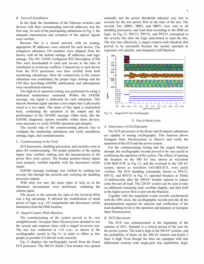
The commissioning of the system proved to be very straightforward. Georgian State Electrosystem decided to test the system and response times with a staged in-service test. The test was conducted at 1:41 a.m., as shown in the oscillographic record in Fig. 13, in order to affect as few people as possible if it did not work correctly.
Fig. 13 displays the oscillography record from the Ksani ECS processor. The 500 kV Kartli 2 line breaker was opened
manually and the power thresholds adjusted very low to account for the low power flow at the time of the test. The severity bits (SB01, SB02, and SB03) were sent to all shedding processors, and load shed according to the HMI set logic. In Fig. 13, PSV31, PSV32, and PSV33 correspond to the severity bits after the logic determined to send the bits. The test was effectively a staged country-wide blackout that proved to be successful because the system operated as expected, very quickly, and mitigated a full blackout.
Fig. 13. Staged ECS Test Oscillography
V. FIELD OPERATION
A. Importance of Oscillography
The ECS processors at the Ksani and Zestaponi substations are capable of storing oscillography. This function allows Georgian State Electrosystem to observe and verify the operation of the ECS and the power system.
For the commissioning testing and the staged blackout attempt, the oscillographic records proved to be very useful in confirming the operation of the system. The effects of opening the breakers on the 500 kV line, shown as waveform IAW-IBW-ICW in Fig. 13, and the overload in the 220 kV system, shown as waveform IAX-IBX-ICX, were easily verified. The ECS shedding commands, shown as PSV31, PSV32, and PSV33 in Fig. 13, operated breakers at Tbilisi 12 milliseconds after the 500 kV breaker opened to reduce some but not all load. The 220 kV system can be seen to take on additional remaining load, oscillate slightly, and then hold at the higher power flow to prevent the blackout.
Together with the sequential events records synchronized with the GPS clock, the oscillographic records provide all the documentation required for analysis and verification of the load-shedding levels to the operators and planners at Georgian State Electrosystem.
B. ECS Operations
The ECS was commissioned at the beginning of the summer of 2011. Summer is a critical period of the year for the power system. The load is high in the 500 kV systems, and the probability of faults on the 500 kV Imereti and Kartli 2 lines is high. Even though the lines are equipped with line differential systems with single-pole trip capabilities, high-
9
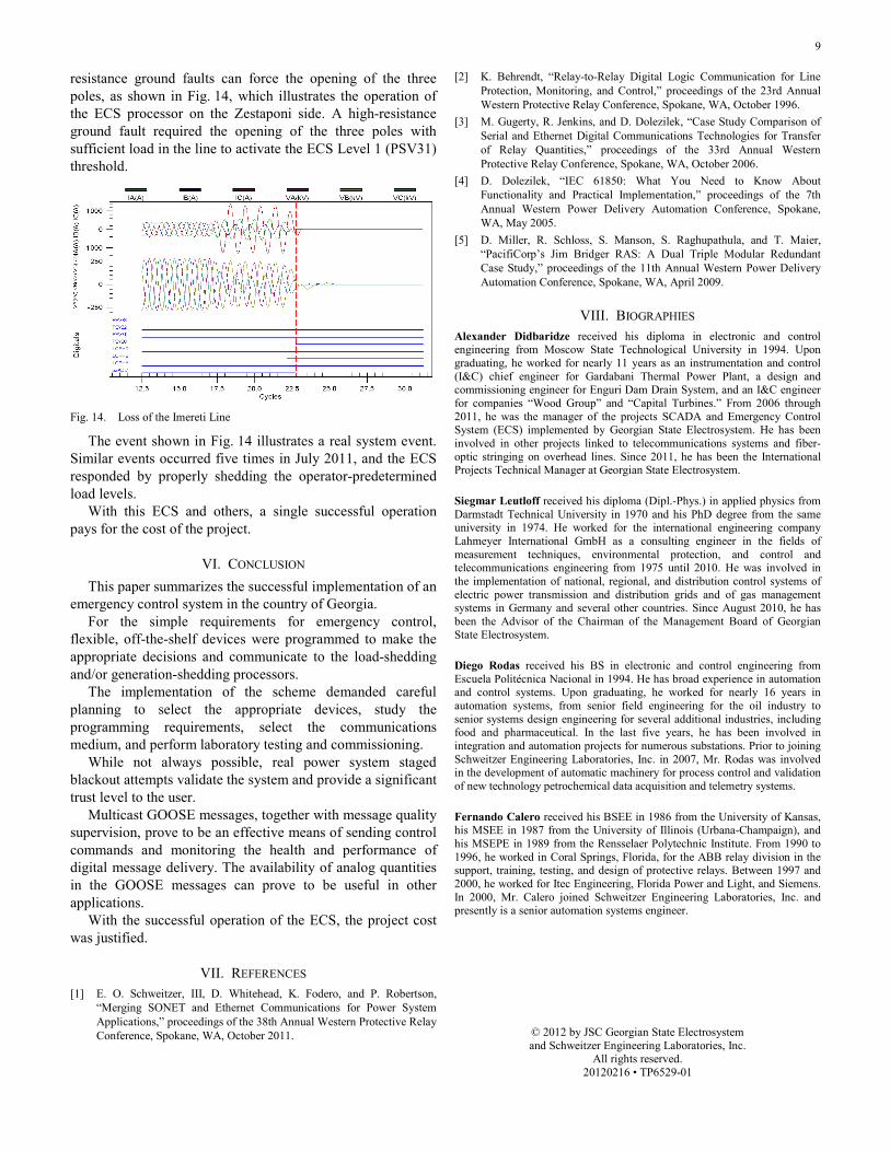
resistance ground faults can force the opening of the three poles, as shown in Fig. 14, which illustrates the operation of the ECS processor on the Zestaponi side. A high-resistance ground fault required the opening of the three poles with sufficient load in the line to activate the ECS Level 1 (PSV31) threshold.
Fig. 14. Loss of the Imereti Line
The event shown in Fig. 14 illustrates a real system event. Similar events occurred five times in July 2011, and the ECS responded by properly shedding the operator-predetermined load levels.
With this ECS and others, a single successful operation pays for the cost of the project.
VI. CONCLUSION
This paper summarizes the successful implementation of an emergency control system in the country of Georgia.
For the simple requirements for emergency control, flexible, off-the-shelf devices were programmed to make the appropriate decisions and communicate to the load-shedding and/or generation-shedding processors.
The implementation of the scheme demanded careful planning to select the appropriate devices, study the programming requirements, select the communications medium, and perform laboratory testing and commissioning.
While not always possible, real power system staged blackout attempts validate the system and provide a significant trust level to the user.
Multicast GOOSE messages, together with message quality supervision, prove to be an effective means of sending control commands and monitoring the health and performance of digital message delivery. The availability of analog quantities in the GOOSE messages can prove to be useful in other applications.
With the successful operation of the ECS, the project cost was justified.
VII. REFERENCES [1] E. O. Schweitzer, III, D. Whitehead, K. Fodero, and P. Robertson,
“Merging SONET and Ethernet Communications for Power System Applications,” proceedings of the 38th Annual Western Protective Relay Conference, Spokane, WA, October 2011.
[2] K. Behrendt, “Relay-to-Relay Digital Logic Communication for Line Protection, Monitoring, and Control,” proceedings of the 23rd Annual Western Protective Relay Conference, Spokane, WA, October 1996.
[3] M. Gugerty, R. Jenkins, and D. Dolezilek, “Case Study Comparison of Serial and Ethernet Digital Communications Technologies for Transfer of Relay Quantities,” proceedings of the 33rd Annual Western Protective Relay Conference, Spokane, WA, October 2006.
[4] D. Dolezilek, “IEC 61850: What You Need to Know About Functionality and Practical Implementation,” proceedings of the 7th Annual Western Power Delivery Automation Conference, Spokane, WA, May 2005.
[5] D. Miller, R. Schloss, S. Manson, S. Raghupathula, and T. Maier, “PacifiCorp’s Jim Bridger RAS: A Dual Triple Modular Redundant Case Study,” proceedings of the 11th Annual Western Power Delivery Automation Conference, Spokane, WA, April 2009.
VIII. BIOGRAPHIES
Alexander Didbaridze received his diploma in electronic and control engineering from Moscow State Technological University in 1994. Upon graduating, he worked for nearly 11 years as an instrumentation and control (I&C) chief engineer for Gardabani Thermal Power Plant, a design and commissioning engineer for Enguri Dam Drain System, and an I&C engineer for companies “Wood Group” and “Capital Turbines.” From 2006 through 2011, he was the manager of the projects SCADA and Emergency Control System (ECS) implemented by Georgian State Electrosystem. He has been involved in other projects linked to telecommunications systems and fiber-optic stringing on overhead lines. Since 2011, he has been the International Projects Technical Manager at Georgian State Electrosystem.
Siegmar Leutloff received his diploma (Dipl.-Phys.) in applied physics from Darmstadt Technical University in 1970 and his PhD degree from the same university in 1974. He worked for the international engineering company Lahmeyer International GmbH as a consulting engineer in the fields of measurement techniques, environmental protection, and control and telecommunications engineering from 1975 until 2010. He was involved in the implementation of national, regional, and distribution control systems of electric power transmission and distribution grids and of gas management systems in Germany and several other countries. Since August 2010, he has been the Advisor of the Chairman of the Management Board of Georgian State Electrosystem.
Diego Rodas received his BS in electronic and control engineering from Escuela Politécnica Nacional in 1994. He has broad experience in automation and control systems. Upon graduating, he worked for nearly 16 years in automation systems, from senior field engineering for the oil industry to senior systems design engineering for several additional industries, including food and pharmaceutical. In the last five years, he has been involved in integration and automation projects for numerous substations. Prior to joining Schweitzer Engineering Laboratories, Inc. in 2007, Mr. Rodas was involved in the development of automatic machinery for process control and validation of new technology petrochemical data acquisition and telemetry systems.
Fernando Calero received his BSEE in 1986 from the University of Kansas, his MSEE in 1987 from the University of Illinois (Urbana-Champaign), and his MSEPE in 1989 from the Rensselaer Polytechnic Institute. From 1990 to 1996, he worked in Coral Springs, Florida, for the ABB relay division in the support, training, testing, and design of protective relays. Between 1997 and 2000, he worked for Itec Engineering, Florida Power and Light, and Siemens. In 2000, Mr. Calero joined Schweitzer Engineering Laboratories, Inc. and presently is a senior automation systems engineer.
© 2012 by JSC Georgian State Electrosystem and Schweitzer Engineering Laboratories, Inc.
All rights reserved. 20120216 • TP6529-01