
Design Illustrations on the Use of Soil Nails to Upgrade...
107
Design Illustrations on the Use of Soil Nails to Upgrade Loose Fill Slopes Geotechnical Engineering Office and The Hong Kong Institution of Engineers (Geotechnical Division) November 2013
Transcript of Design Illustrations on the Use of Soil Nails to Upgrade...
Design Illustrations on the Use of Soil Nails to
Upgrade Loose Fill Slopes
Geotechnical Engineering Office and
The Hong Kong Institution of Engineers (Geotechnical Division)
November 2013

2
Disclaimer This report presents design examples with reference to the guidelines given in “Geoguide 7: Guide to Soil Nail Design and Construction” promulgated by the Geotechnical Engineering Office of the Civil Engineering and Development Department (GEO/CEDD), and new design recommendations suggested in the report entitled “Design of Soil Nails for Upgrading Loose Fill Slopes” jointly published by the GEO/CEDD and the Hong Kong Institution of Engineers, Geotechnical Division (GEO-HKIE, 2011). The Hong Kong Institution of Engineers and GEO/CEDD do not accept any responsibility for the use or misuse of this report. A designer using the recommendations contained in this report shall retain total responsibility for the adequacy of the design.
3
Abstract
Based on the findings from a study initiated by the Geotechnical Engineering Office of the Civil Engineering and Development Department (GEO/CEDD), new design guidelines which supplement the original design guidance for the use of soil nails to upgrade loose fill slopes have been recommended and are summarised in a report jointly published by the GEO/CEDD, and The Hong Kong Institution of Engineers, Geotechnical Division (GEO-HKIE, 2011). The new guidelines recommend the use of a hybrid nail arrangement comprising soil nails at two different orientations. A design procedure for delineating loose fill at great depths which can be assumed to be non-liquefiable is also recommended.
To demonstrate the implementation of the new
recommendations given in the GEO-HKIE (2011) Report, GEO-HKIE prepared three worked examples pursuant to the new recommendations, which are presented in this report. The first example demonstrates the procedure for adopting the hybrid nail arrangement, which is a novelty to local practitioners. The second example assumes that steeply inclined nails have to be adopted due to site constraints. The design therefore includes the provision of an embedded concrete footing which aims to reduce slope deformation. The effectiveness of the nail arrangement is verified by numerical analysis. The last example considers a fill slope with loose fill of a considerable depth, and illustrates the procedure to delineate the non-liquefiable loose fill zone by limit equilibrium method. Recommendations in respect of the selection of design parameters are also presented in the worked examples. The draft version of this report was issued in April 2013, and circulated for comments among government departments and practitioners via The Hong Kong Institution of Engineers, Geotechnical Division (HKIE-GD). These comments and the responses are attached in Appendix B. The salient points of these comments and responses are summarised in Section 5. The worked examples serve to illustrate the principles of the design guidelines only, and the design parameters, assumptions and considerations adopted in the worked examples are not meant to be adopted for general design purposes. Designers should use design parameters appropriate to their project at hand.
4
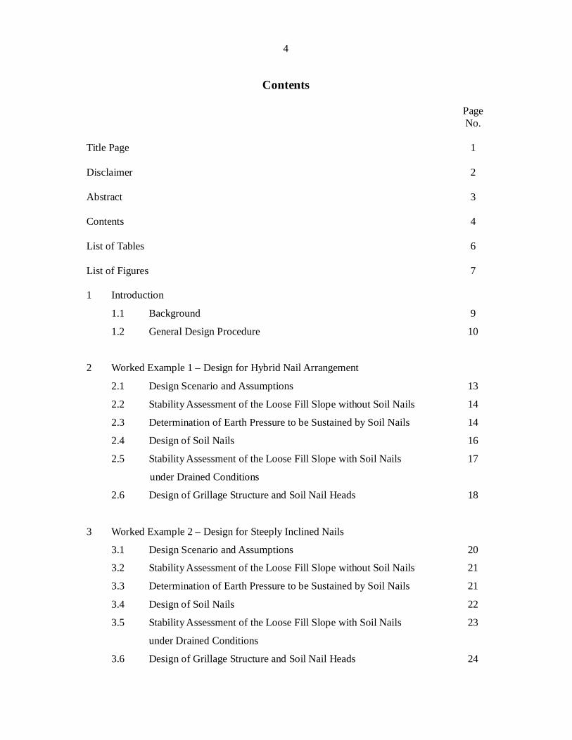
Contents
Page No. Title Page 1 Disclaimer 2 Abstract 3 Contents 4 List of Tables 6 List of Figures 7 1 Introduction
1.1 Background 9
1.2 General Design Procedure 10
2 Worked Example 1 – Design for Hybrid Nail Arrangement
2.1 Design Scenario and Assumptions 13
2.2 Stability Assessment of the Loose Fill Slope without Soil Nails 14
2.3 Determination of Earth Pressure to be Sustained by Soil Nails 14
2.4 Design of Soil Nails 16
2.5 Stability Assessment of the Loose Fill Slope with Soil Nails 17
under Drained Conditions
2.6 Design of Grillage Structure and Soil Nail Heads 18
3 Worked Example 2 – Design for Steeply Inclined Nails
3.1 Design Scenario and Assumptions 20
3.2 Stability Assessment of the Loose Fill Slope without Soil Nails 21
3.3 Determination of Earth Pressure to be Sustained by Soil Nails 21
3.4 Design of Soil Nails 22
3.5 Stability Assessment of the Loose Fill Slope with Soil Nails 23
under Drained Conditions
3.6 Design of Grillage Structure and Soil Nail Heads 24
5
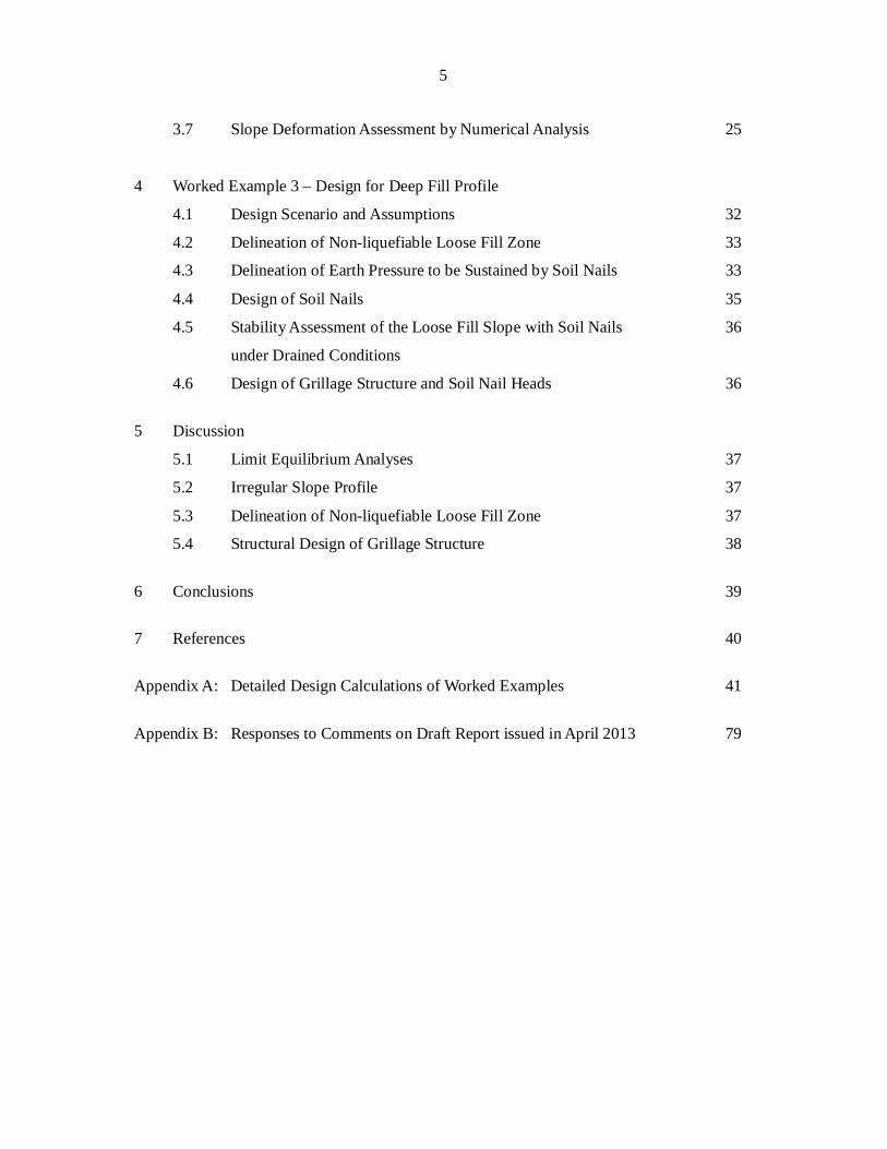
3.7 Slope Deformation Assessment by Numerical Analysis 25
4 Worked Example 3 – Design for Deep Fill Profile
4.1 Design Scenario and Assumptions 32
4.2 Delineation of Non-liquefiable Loose Fill Zone 33
4.3 Delineation of Earth Pressure to be Sustained by Soil Nails 33
4.4 Design of Soil Nails 35
4.5 Stability Assessment of the Loose Fill Slope with Soil Nails 36
under Drained Conditions
4.6 Design of Grillage Structure and Soil Nail Heads 36
5 Discussion
5.1 Limit Equilibrium Analyses 37
5.2 Irregular Slope Profile 37
5.3 Delineation of Non-liquefiable Loose Fill Zone 37
5.4 Structural Design of Grillage Structure 38
6 Conclusions 39
7 References 40
Appendix A: Detailed Design Calculations of Worked Examples 41
Appendix B: Responses to Comments on Draft Report issued in April 2013 79
6
List of Tables
Table No.
Page No.
2.1 Design Soil Parameters in Worked Example 1
14
3.1 Design Soil Parameters in Worked Example 2
21
3.2 Model Parameters for Soils in the Numerical Analysis
27
3.3 Model Parameters for Soil Nails and Grillage Facing in the Numerical Analysis
29
4.1 Design Soil Parameters in Worked Example 3
32
7
List of Figures
Figure No.
Page No.
2.1 Slope Geometry of Worked Example 1
13
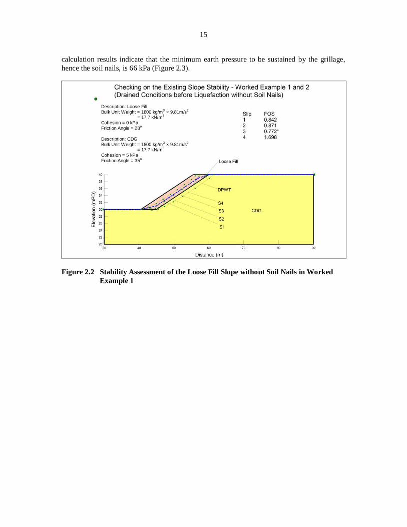
2.2 Stability Assessment of the Loose Fill Slope without Soil Nails in Worked Example 1
15
2.3 Determination of Earth Pressure Exerted on Grillage Facing upon Liquefaction in Worked Example 1
16
2.4 Soil Nail Arrangement of Worked Example 1
17
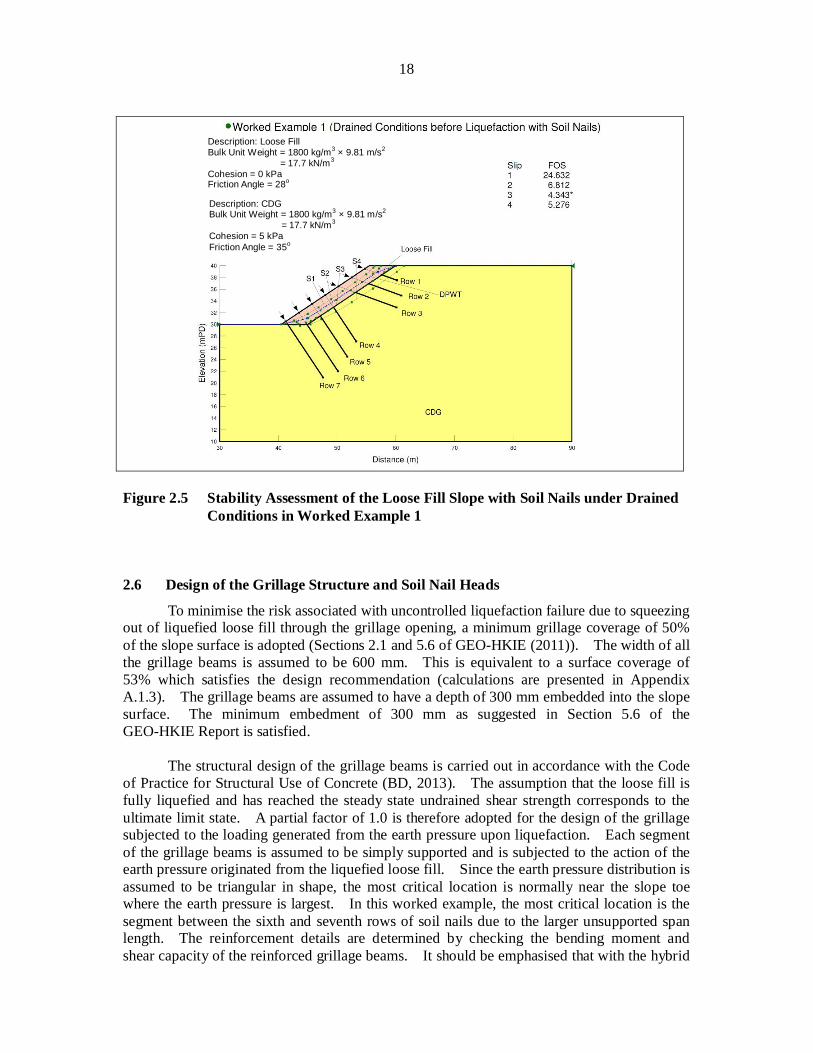
2.5 Stability Assessment of the Loose Fill Slope with Soil Nails under Drained Conditions in Worked Example 1
18
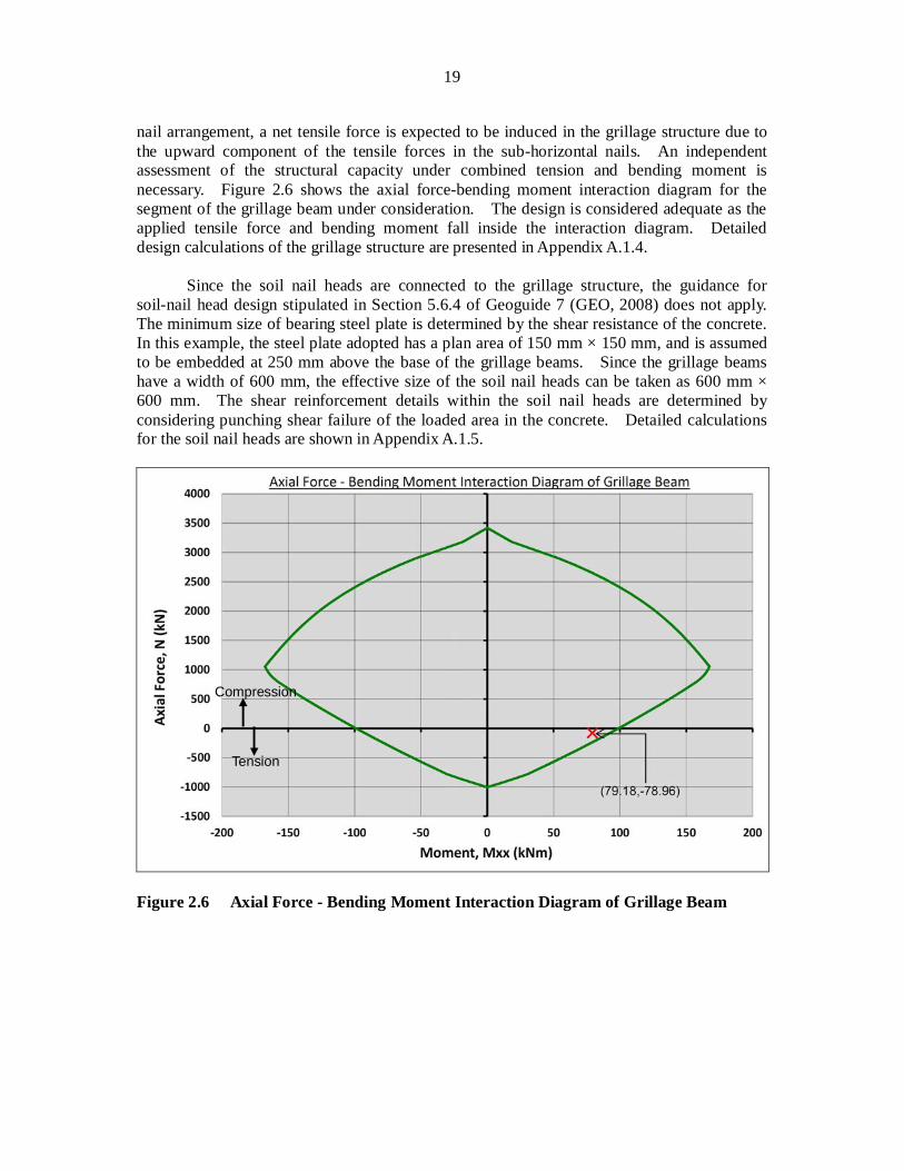
2.6 Axial Force – Bending Moment Interaction Diagram of Grillage Beam
19
3.1 Slope Geometry of Worked Example 2
20
3.2 Determination of Earth Pressure Exerted on Grillage Facing upon Liquefaction in Worked Example 2
22
3.3 Soil Nail Arrangement of Worked Example 2
23
3.4 Stability Assessment of the Loose Fill Slope with Soil Nails under Drained Conditions in Worked Example 2
24
3.5 Model Geometry and Initial Pore Water Pressure Distribution in the Numerical Model
25
3.6 Shear Strength Parameters of the Loose Fill before Interface Liquefaction
28
3.7 Undrained Shear Strength of the Loose Fill after Interface Liquefaction
28
3.8 Comparison of Design Nail Forces and Mobilised Nail Forces upon Interface Liquefaction
30
3.9 Slope Deformation Predicted by the Numerical Analysis
31
4.1 Slope Geometry of Worked Example 3
33
8
Figure No.
Page No.
4.2 Delineation of Non-liquefiable Loose Fill Zone
34
4.3 Determination of Earth Pressure Exerted on Grillage Facing upon Liquefaction in Worked Example 3
34
4.4 Soil Nail Arrangement of Worked Example 3
35
4.5 Stability Assessment of Loose Fill Slope with Soil Nails under Drained Conditions in Worked Example 3
36
9
1 Introduction
1.1 Background
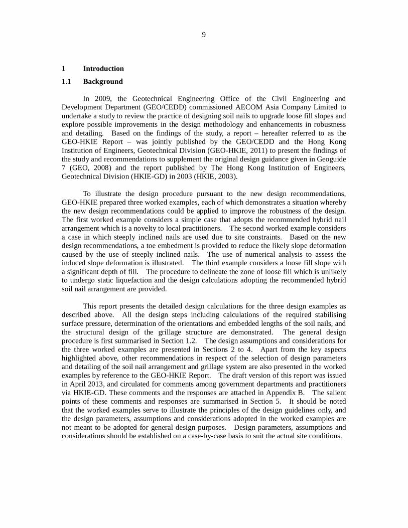
In 2009, the Geotechnical Engineering Office of the Civil Engineering and Development Department (GEO/CEDD) commissioned AECOM Asia Company Limited to undertake a study to review the practice of designing soil nails to upgrade loose fill slopes and explore possible improvements in the design methodology and enhancements in robustness and detailing. Based on the findings of the study, a report – hereafter referred to as the GEO-HKIE Report – was jointly published by the GEO/CEDD and the Hong Kong Institution of Engineers, Geotechnical Division (GEO-HKIE, 2011) to present the findings of the study and recommendations to supplement the original design guidance given in Geoguide 7 (GEO, 2008) and the report published by The Hong Kong Institution of Engineers, Geotechnical Division (HKIE-GD) in 2003 (HKIE, 2003).
To illustrate the design procedure pursuant to the new design recommendations, GEO-HKIE prepared three worked examples, each of which demonstrates a situation whereby the new design recommendations could be applied to improve the robustness of the design. The first worked example considers a simple case that adopts the recommended hybrid nail arrangement which is a novelty to local practitioners. The second worked example considers a case in which steeply inclined nails are used due to site constraints. Based on the new design recommendations, a toe embedment is provided to reduce the likely slope deformation caused by the use of steeply inclined nails. The use of numerical analysis to assess the induced slope deformation is illustrated. The third example considers a loose fill slope with a significant depth of fill. The procedure to delineate the zone of loose fill which is unlikely to undergo static liquefaction and the design calculations adopting the recommended hybrid soil nail arrangement are provided.
This report presents the detailed design calculations for the three design examples as described above. All the design steps including calculations of the required stabilising surface pressure, determination of the orientations and embedded lengths of the soil nails, and the structural design of the grillage structure are demonstrated. The general design procedure is first summarised in Section 1.2. The design assumptions and considerations for the three worked examples are presented in Sections 2 to 4. Apart from the key aspects highlighted above, other recommendations in respect of the selection of design parameters and detailing of the soil nail arrangement and grillage system are also presented in the worked examples by reference to the GEO-HKIE Report. The draft version of this report was issued in April 2013, and circulated for comments among government departments and practitioners via HKIE-GD. These comments and the responses are attached in Appendix B. The salient points of these comments and responses are summarised in Section 5. It should be noted that the worked examples serve to illustrate the principles of the design guidelines only, and the design parameters, assumptions and considerations adopted in the worked examples are not meant to be adopted for general design purposes. Design parameters, assumptions and considerations should be established on a case-by-case basis to suit the actual site conditions.
10
1.2 General Design Procedure
The general design procedure consists of the following steps:
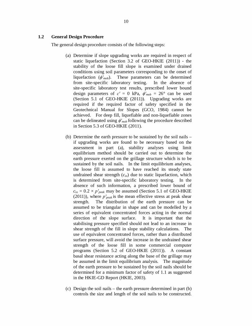
(a) Determine if slope upgrading works are required in respect of static liquefaction (Section 3.2 of GEO-HKIE (2011)) - the stability of the loose fill slope is examined under drained conditions using soil parameters corresponding to the onset of liquefaction ( mob). These parameters can be determined from site-specific laboratory testing. In the absence of site-specific laboratory test results, prescribed lower bound design parameters of = 0 kPa, mob = 26° can be used (Section 5.1 of GEO-HKIE (2011)). Upgrading works are required if the required factor of safety specified in the Geotechnical Manual for Slopes (GCO, 1984) cannot be achieved. For deep fill, liquefiable and non-liquefiable zones can be delineated using mob following the procedure described in Section 5.3 of GEO-HKIE (2011).
(b) Determine the earth pressure to be sustained by the soil nails –
if upgrading works are found to be necessary based on the assessment in part (a), stability analyses using limit equilibrium method should be carried out to determine the earth pressure exerted on the grillage structure which is to be sustained by the soil nails. In the limit equilibrium analyses, the loose fill is assumed to have reached its steady state undrained shear strength (css) due to static liquefaction, which is determined from site-specific laboratory testing. In the absence of such information, a prescribed lower bound of css = 0.2 × peak may be assumed (Section 5.1 of GEO-HKIE (2011)), where peak is the mean effective stress at peak shear strength. The distribution of the earth pressure can be assumed to be triangular in shape and can be modelled by a series of equivalent concentrated forces acting in the normal direction of the slope surface. It is important that the stabilising pressure specified should not lead to an increase in shear strength of the fill in slope stability calculations. The use of equivalent concentrated forces, rather than a distributed surface pressure, will avoid the increase in the undrained shear strength of the loose fill in some commercial computer programs (Section 5.2 of GEO-HKIE (2011)). A constant basal shear resistance acting along the base of the grillage may be assumed in the limit equilibrium analysis. The magnitude of the earth pressure to be sustained by the soil nails should be determined for a minimum factor of safety of 1.1 as suggested in the HKIE-GD Report (HKIE, 2003).
(c) Design the soil nails – the earth pressure determined in part (b)
controls the size and length of the soil nails to be constructed.
11
For enhanced robustness, a hybrid nail arrangement should be adopted (Section 5.4 of GEO-HKIE (2011)). The soil nails at the upper portion of the slope can be designed to be sub-horizontal (e.g. with an inclination of about 20° to the horizontal), whilst the remaining nails are assumed to be perpendicular to the slope surface. According to Section 5.4 of GEO-HKIE (2011), the ratio of sub-horizontal nails to steeply inclined nails can be estimated by considering force equilibrium of the grillage facing. The number of sub-horizontal nails should be approximately 40% to 50% of total number of soil nails to ensure sufficient sub-horizontal nails are present to counter sliding failure. The size and length of the nails are then determined by considering three internal failure modes, namely tensile failure of steel bar, bond failure between grout and steel reinforcement, and shear failure of the adjacent ground of the soil nail. The corresponding factors of safety are given in HKIE (2003) and Geoguide 7 (GEO, 2008). If hybrid nail arrangement is not used, numerical analysis should be carried out to study the robustness and effectiveness of the soil nail design.
(d) Confirm the adequacy of the design under drained conditions –
the stability of the loose fill slope under drained conditions is examined assuming that the designed soil nail forces are mobilised. The design is considered adequate if the required factor of safety used in part (a) can be achieved.
(e) Design the grillage structure – the size of the grillage beams is
governed by the structural forces that the grillage has to sustain and the minimum coverage area of the grillage on the slope surface such that the risk of uncontrolled liquefaction due to squeezing out of the liquefied loose fill through the grillage opening is reasonably low. The grillage beams are designed to sustain the combined action of the earth pressure generated from the liquefied loose fill and the forces mobilised in the soil nails. The structural design can be performed according to Code of Practice for Structural Use of Concrete (BD, 2013). For slopes not higher than 25 m, a minimum grillage coverage of 50% of the slope surface is considered acceptable (Sections 2.1 and 5.6 of GEO-HKIE (2011)). A minimum grillage embedment of 0.3 m is considered adequate (Section 5.6 of GEO-HKIE (2011)).
(f) Design the soil nail heads – the soil nail heads should be
designed against bearing and punching shear failure around the loaded area based on the guidelines set out in Code of Practice for Structural Use of Concrete (BD, 2013). The minimum size of the steel plate should be determined such that the bearing pressure, generated from the nail force, can be

12
sustained by the concrete shear resistance. In addition, the shear reinforcement within the soil nail heads should be designed to sustain the maximum shear stress generated in the concrete by the nail force.
13
2 Worked Example 1 – Design for Hybrid Nail Arrangement
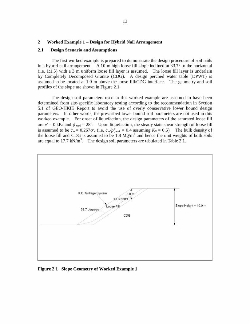
2.1 Design Scenario and Assumptions The first worked example is prepared to demonstrate the design procedure of soil nails
in a hybrid nail arrangement. A 10 m high loose fill slope inclined at 33.7° to the horizontal (i.e. 1:1.5) with a 3 m uniform loose fill layer is assumed. The loose fill layer is underlain by Completely Decomposed Granite (CDG). A design perched water table (DPWT) is assumed to be located at 1.0 m above the loose fill/CDG interface. The geometry and soil profiles of the slope are shown in Figure 2.1.
The design soil parameters used in this worked example are assumed to have been
determined from site-specific laboratory testing according to the recommendation in Section 5.1 of GEO-HKIE Report to avoid the use of overly conservative lower bound design parameters. In other words, the prescribed lower bound soil parameters are not used in this worked example. For onset of liquefaction, the design parameters of the saturated loose fill are = 0 kPa and mob = 28°. Upon liquefaction, the steady state shear strength of loose fill is assumed to be css = 0.267 v (i.e. css/p peak = 0.4 assuming K0 = 0.5). The bulk density of the loose fill and CDG is assumed to be 1.8 Mg/m3 and hence the unit weights of both soils are equal to 17.7 kN/m3. The design soil parameters are tabulated in Table 2.1.
Figure 2.1 Slope Geometry of Worked Example 1
14
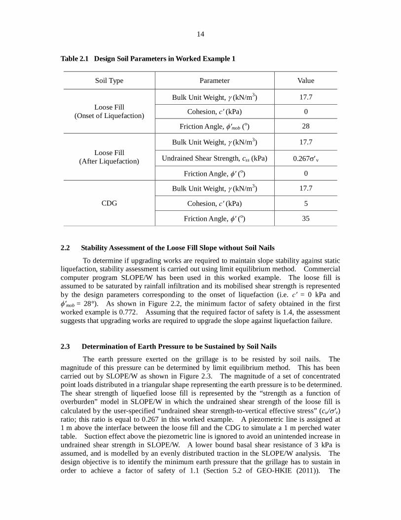
Table 2.1 Design Soil Parameters in Worked Example 1
Soil Type Parameter Value
Loose Fill (Onset of Liquefaction)
Bulk Unit Weight, (kN/m3) 17.7
Cohesion, (kPa) 0
Friction Angle, mob (o) 28
Loose Fill (After Liquefaction)
Bulk Unit Weight, (kN/m3) 17.7
Undrained Shear Strength, css (kPa) 0.267 v
Friction Angle, (o) 0
CDG
Bulk Unit Weight, (kN/m3) 17.7
Cohesion, (kPa) 5
Friction Angle, (o) 35 2.2 Stability Assessment of the Loose Fill Slope without Soil Nails
To determine if upgrading works are required to maintain slope stability against static liquefaction, stability assessment is carried out using limit equilibrium method. Commercial computer program SLOPE/W has been used in this worked example. The loose fill is assumed to be saturated by rainfall infiltration and its mobilised shear strength is represented by the design parameters corresponding to the onset of liquefaction (i.e. = 0 kPa and
mob = 28°). As shown in Figure 2.2, the minimum factor of safety obtained in the first worked example is 0.772. Assuming that the required factor of safety is 1.4, the assessment suggests that upgrading works are required to upgrade the slope against liquefaction failure. 2.3 Determination of Earth Pressure to be Sustained by Soil Nails
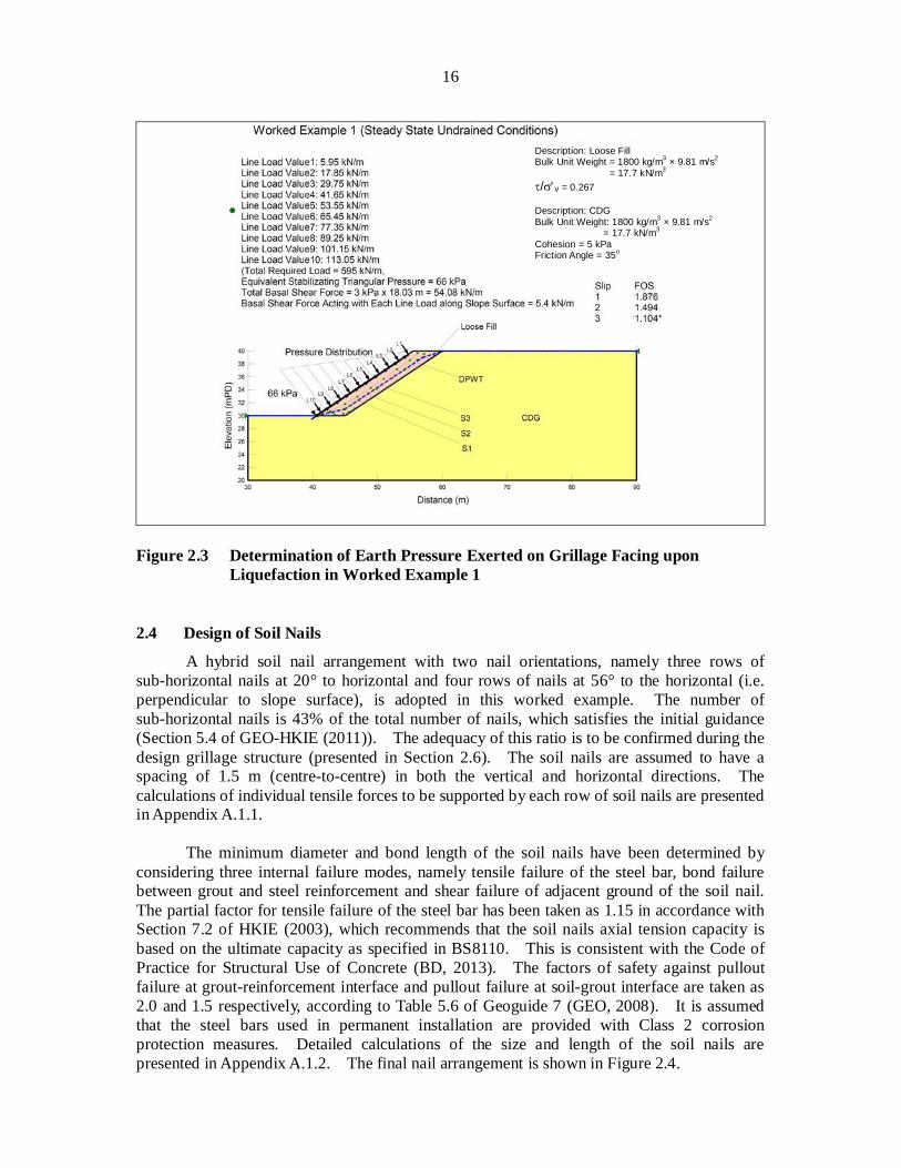
The earth pressure exerted on the grillage is to be resisted by soil nails. The magnitude of this pressure can be determined by limit equilibrium method. This has been carried out by SLOPE/W as shown in Figure 2.3. The magnitude of a set of concentrated point loads distributed in a triangular shape representing the earth pressure is to be determined. The shear strength of liquefied loose fill is represented by the “strength as a function of overburden” model in SLOPE/W in which the undrained shear strength of the loose fill is calculated by the user-specified “undrained shear strength-to-vertical effective stress” (cu/ v) ratio; this ratio is equal to 0.267 in this worked example. A piezometric line is assigned at 1 m above the interface between the loose fill and the CDG to simulate a 1 m perched water table. Suction effect above the piezometric line is ignored to avoid an unintended increase in undrained shear strength in SLOPE/W. A lower bound basal shear resistance of 3 kPa is assumed, and is modelled by an evenly distributed traction in the SLOPE/W analysis. The design objective is to identify the minimum earth pressure that the grillage has to sustain in order to achieve a factor of safety of 1.1 (Section 5.2 of GEO-HKIE (2011)). The
15
calculation results indicate that the minimum earth pressure to be sustained by the grillage, hence the soil nails, is 66 kPa (Figure 2.3).
Figure 2.2 Stability Assessment of the Loose Fill Slope without Soil Nails in Worked
Example 1
Description: Loose Fill Bulk Unit Weight = 1800 kg/m3 × 9.81m/s2
= 17.7 kN/m3 Cohesion = 0 kPa Friction Angle = 28o Description: CDG Bulk Unit Weight = 1800 kg/m3 × 9.81m/s2
= 17.7 kN/m3 Cohesion = 5 kPa Friction Angle = 35o
16
Figure 2.3 Determination of Earth Pressure Exerted on Grillage Facing upon
Liquefaction in Worked Example 1 2.4 Design of Soil Nails
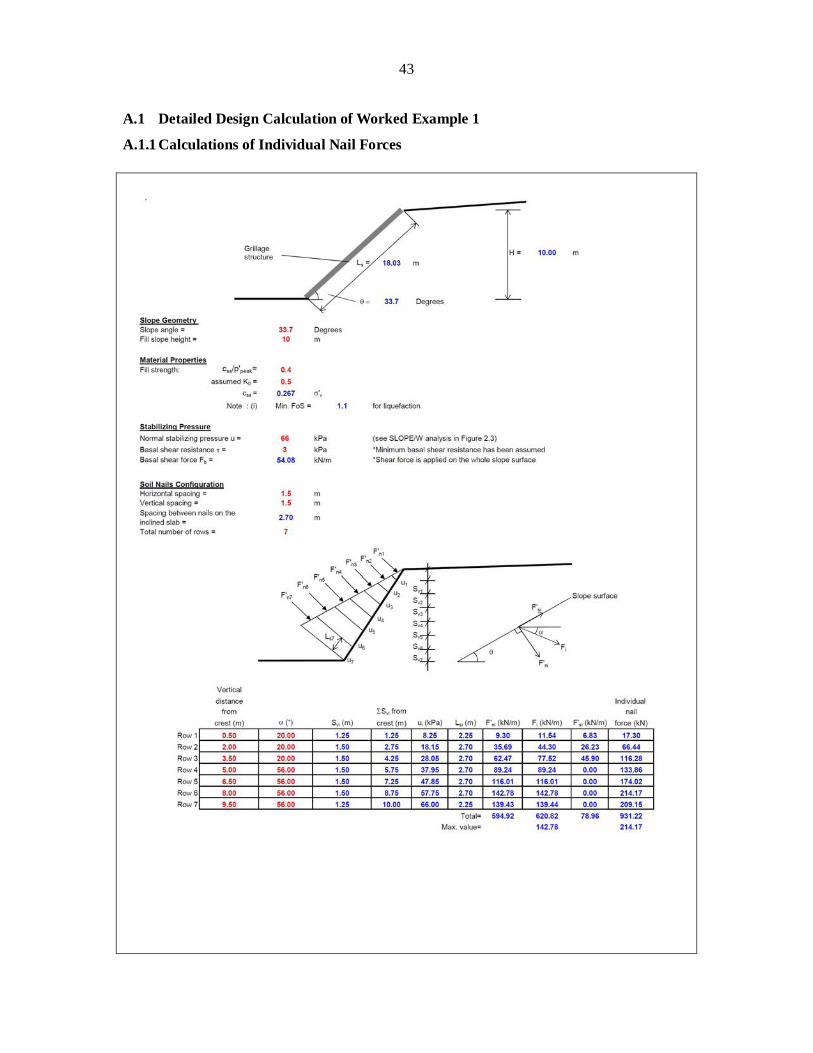
A hybrid soil nail arrangement with two nail orientations, namely three rows of sub-horizontal nails at 20° to horizontal and four rows of nails at 56° to the horizontal (i.e. perpendicular to slope surface), is adopted in this worked example. The number of sub-horizontal nails is 43% of the total number of nails, which satisfies the initial guidance (Section 5.4 of GEO-HKIE (2011)). The adequacy of this ratio is to be confirmed during the design grillage structure (presented in Section 2.6). The soil nails are assumed to have a spacing of 1.5 m (centre-to-centre) in both the vertical and horizontal directions. The calculations of individual tensile forces to be supported by each row of soil nails are presented in Appendix A.1.1.
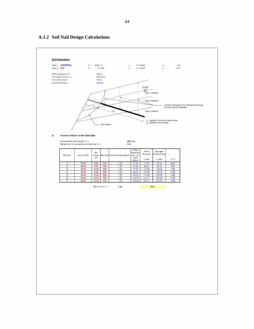
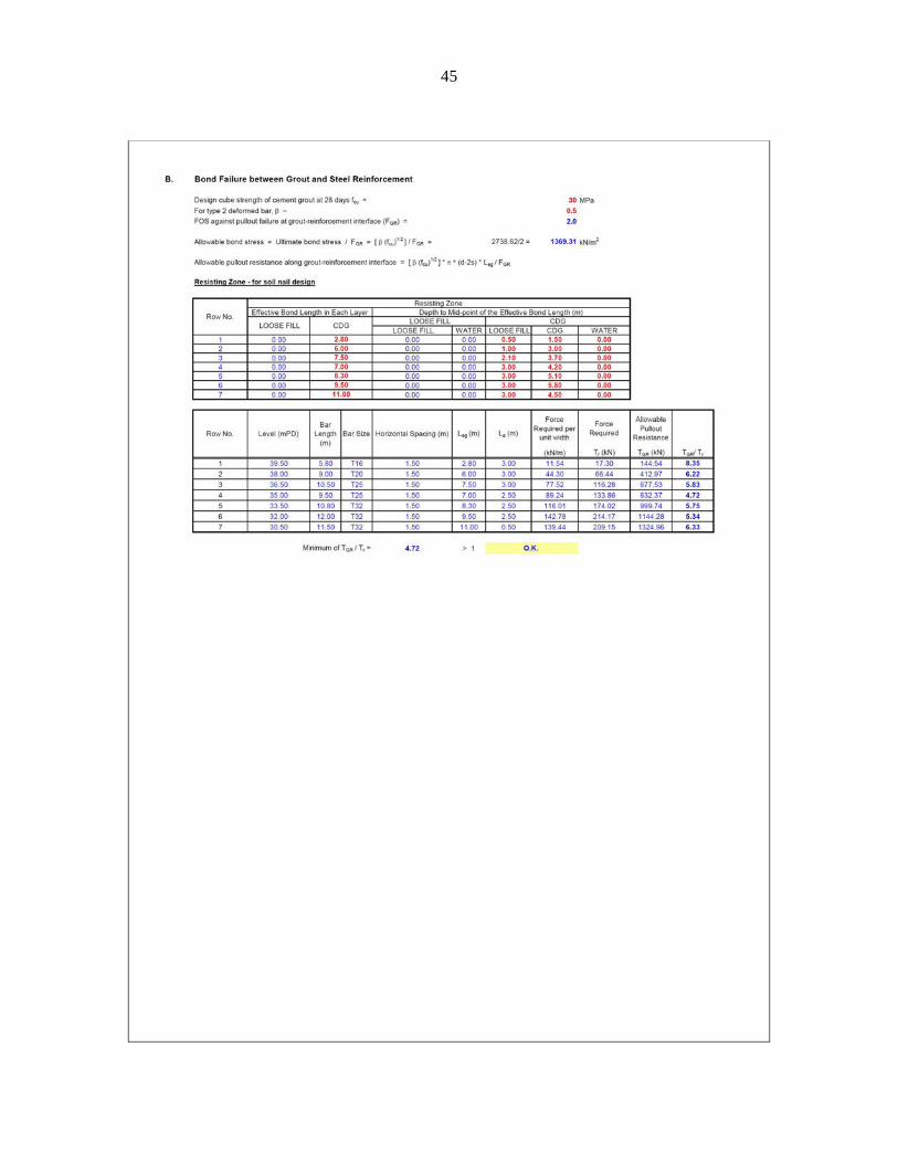
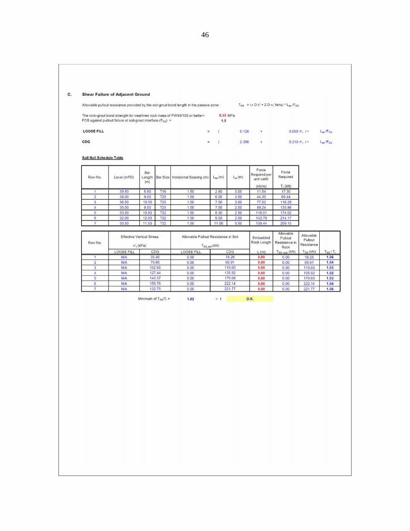
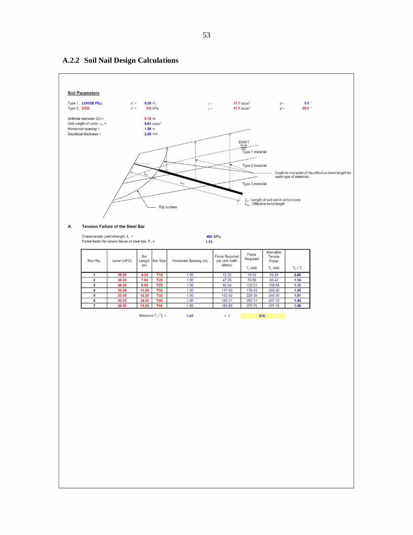
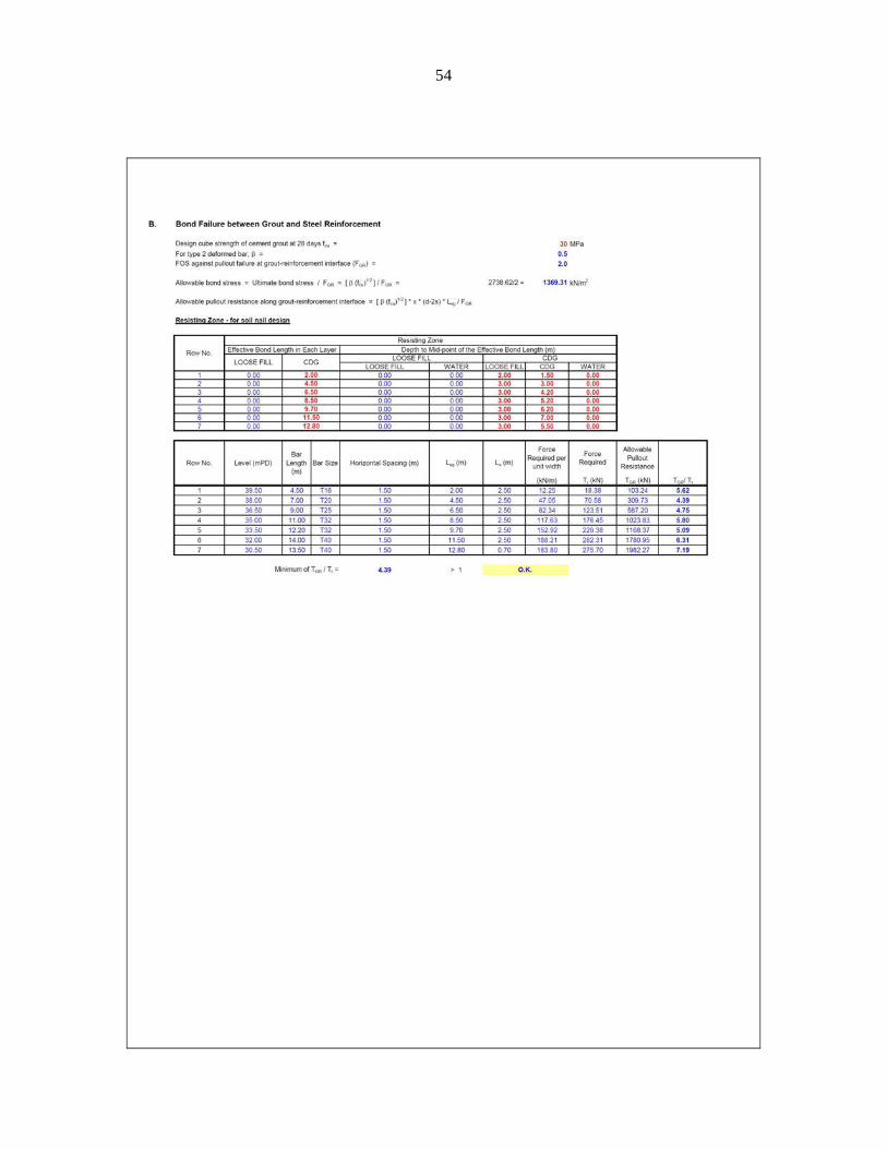
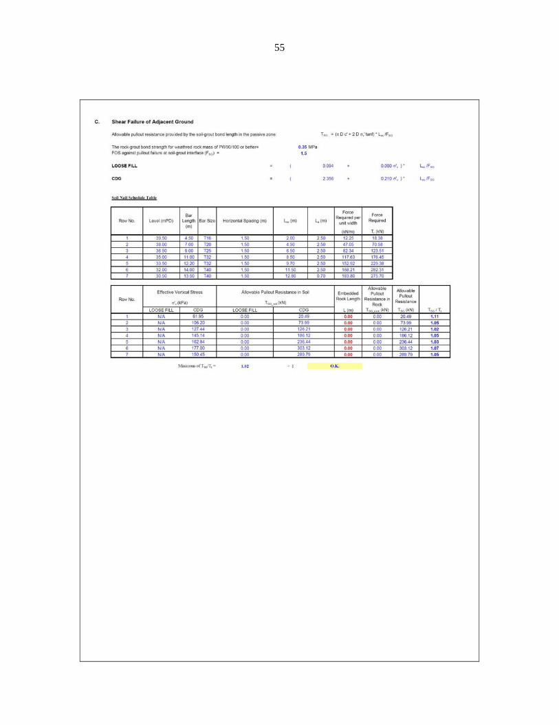
The minimum diameter and bond length of the soil nails have been determined by
considering three internal failure modes, namely tensile failure of the steel bar, bond failure between grout and steel reinforcement and shear failure of adjacent ground of the soil nail. The partial factor for tensile failure of the steel bar has been taken as 1.15 in accordance with Section 7.2 of HKIE (2003), which recommends that the soil nails axial tension capacity is based on the ultimate capacity as specified in BS8110. This is consistent with the Code of Practice for Structural Use of Concrete (BD, 2013). The factors of safety against pullout failure at grout-reinforcement interface and pullout failure at soil-grout interface are taken as 2.0 and 1.5 respectively, according to Table 5.6 of Geoguide 7 (GEO, 2008). It is assumed that the steel bars used in permanent installation are provided with Class 2 corrosion protection measures. Detailed calculations of the size and length of the soil nails are presented in Appendix A.1.2. The final nail arrangement is shown in Figure 2.4.
Description: Loose Fill Bulk Unit Weight = 1800 kg/m3 × 9.81 m/s2
= 17.7 kN/m3 / v = 0.267
Description: CDG Bulk Unit Weight: 1800 kg/m3 × 9.81 m/s2
= 17.7 kN/m3 Cohesion = 5 kPa Friction Angle = 35o

17
Figure 2.4 Soil Nail Arrangement of Worked Example 1 2.5 Stability Assessment of the Loose Fill Slope with Soil Nails under Drained
Conditions After individual nail forces are determined (as shown in Appendix A.1.1), stability of
the nailed slope under drained conditions needs to be verified. This can be assessed by limit equilibrium method assuming that the loose fill is saturated by rainfall infiltration and that the presence of the soil nails avoids liquefaction from triggering. Therefore, in this assessment, the loose fill is represented by the design parameters at the onset of liquefaction (i.e. = 0 kPa and mob = 28°). In this worked example, this assessment has been carried out using SLOPE/W in which the design nail forces at the intended nail orientations are specified as shown in Figure 2.5. The calculated minimum factor of safety is above 1.4, which is the assumed minimum factor of safety as described in Section 2.2. The design is therefore considered adequate.
18
Figure 2.5 Stability Assessment of the Loose Fill Slope with Soil Nails under Drained
Conditions in Worked Example 1
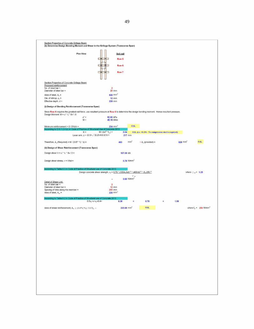
2.6 Design of the Grillage Structure and Soil Nail Heads
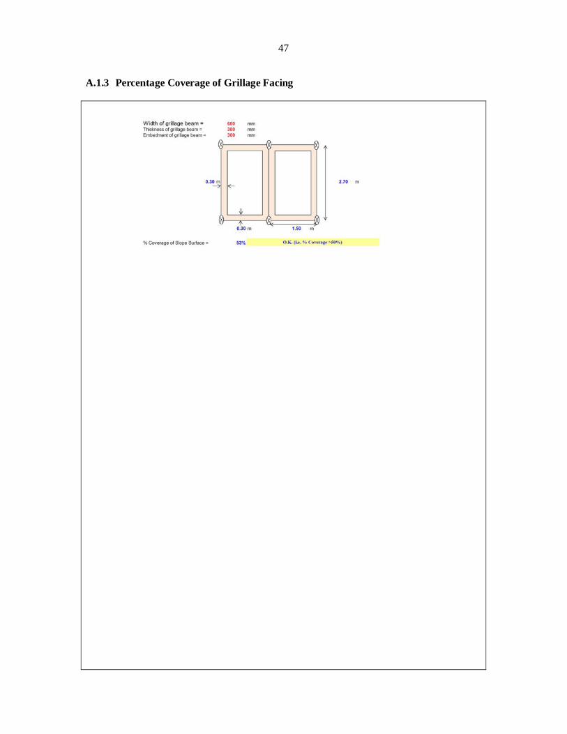
To minimise the risk associated with uncontrolled liquefaction failure due to squeezing out of liquefied loose fill through the grillage opening, a minimum grillage coverage of 50% of the slope surface is adopted (Sections 2.1 and 5.6 of GEO-HKIE (2011)). The width of all the grillage beams is assumed to be 600 mm. This is equivalent to a surface coverage of 53% which satisfies the design recommendation (calculations are presented in Appendix A.1.3). The grillage beams are assumed to have a depth of 300 mm embedded into the slope surface. The minimum embedment of 300 mm as suggested in Section 5.6 of the GEO-HKIE Report is satisfied.
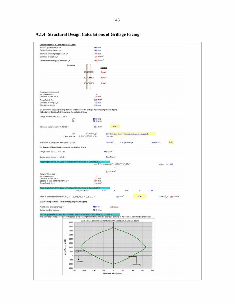
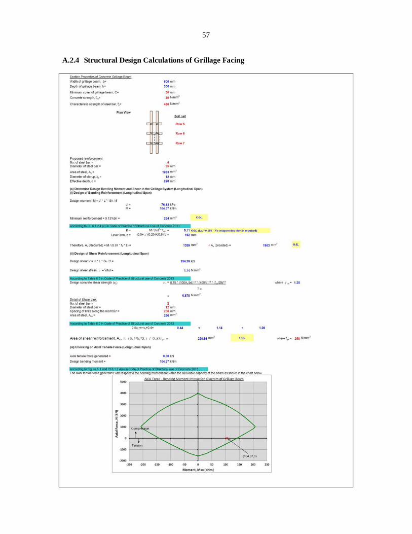
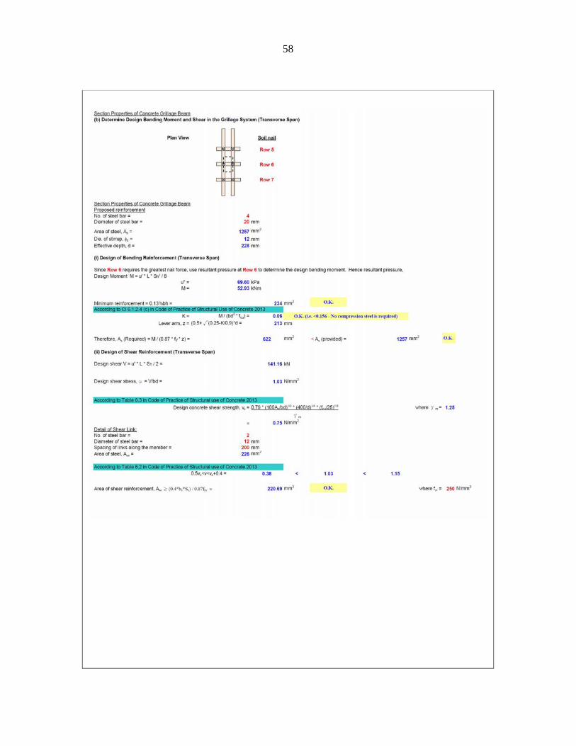
The structural design of the grillage beams is carried out in accordance with the Code
of Practice for Structural Use of Concrete (BD, 2013). The assumption that the loose fill is fully liquefied and has reached the steady state undrained shear strength corresponds to the ultimate limit state. A partial factor of 1.0 is therefore adopted for the design of the grillage subjected to the loading generated from the earth pressure upon liquefaction. Each segment of the grillage beams is assumed to be simply supported and is subjected to the action of the earth pressure originated from the liquefied loose fill. Since the earth pressure distribution is assumed to be triangular in shape, the most critical location is normally near the slope toe where the earth pressure is largest. In this worked example, the most critical location is the segment between the sixth and seventh rows of soil nails due to the larger unsupported span length. The reinforcement details are determined by checking the bending moment and shear capacity of the reinforced grillage beams. It should be emphasised that with the hybrid
Description: CDG Bulk Unit Weight = 1800 kg/m3 × 9.81 m/s2
= 17.7 kN/m3 Cohesion = 5 kPa Friction Angle = 35o
Description: Loose Fill Bulk Unit Weight = 1800 kg/m3 × 9.81 m/s2
= 17.7 kN/m3 Cohesion = 0 kPa Friction Angle = 28o
19
nail arrangement, a net tensile force is expected to be induced in the grillage structure due to the upward component of the tensile forces in the sub-horizontal nails. An independent assessment of the structural capacity under combined tension and bending moment is necessary. Figure 2.6 shows the axial force-bending moment interaction diagram for the segment of the grillage beam under consideration. The design is considered adequate as the applied tensile force and bending moment fall inside the interaction diagram. Detailed design calculations of the grillage structure are presented in Appendix A.1.4.
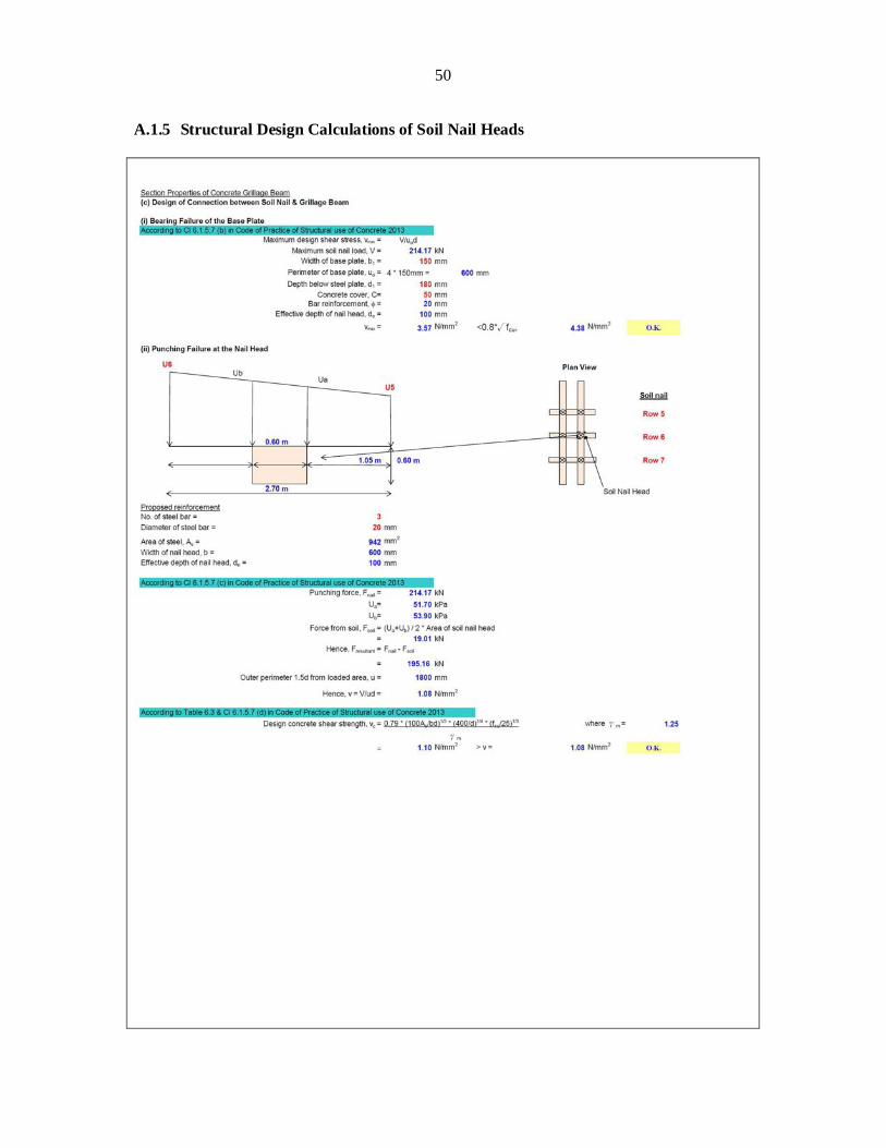
Since the soil nail heads are connected to the grillage structure, the guidance for
soil-nail head design stipulated in Section 5.6.4 of Geoguide 7 (GEO, 2008) does not apply. The minimum size of bearing steel plate is determined by the shear resistance of the concrete. In this example, the steel plate adopted has a plan area of 150 mm × 150 mm, and is assumed to be embedded at 250 mm above the base of the grillage beams. Since the grillage beams have a width of 600 mm, the effective size of the soil nail heads can be taken as 600 mm × 600 mm. The shear reinforcement details within the soil nail heads are determined by considering punching shear failure of the loaded area in the concrete. Detailed calculations for the soil nail heads are shown in Appendix A.1.5.
Figure 2.6 Axial Force - Bending Moment Interaction Diagram of Grillage Beam
Compression
Tension
20
3 Worked Example 2 – Design for Steeply Inclined Nails
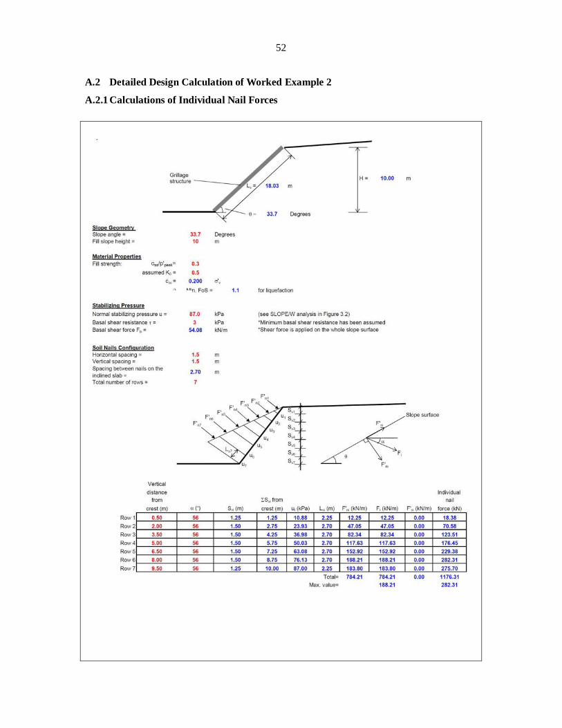
3.1 Design Scenario and Assumptions
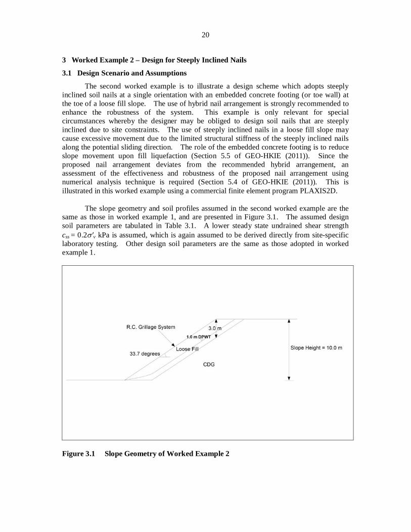
The second worked example is to illustrate a design scheme which adopts steeply inclined soil nails at a single orientation with an embedded concrete footing (or toe wall) at the toe of a loose fill slope. The use of hybrid nail arrangement is strongly recommended to enhance the robustness of the system. This example is only relevant for special circumstances whereby the designer may be obliged to design soil nails that are steeply inclined due to site constraints. The use of steeply inclined nails in a loose fill slope may cause excessive movement due to the limited structural stiffness of the steeply inclined nails along the potential sliding direction. The role of the embedded concrete footing is to reduce slope movement upon fill liquefaction (Section 5.5 of GEO-HKIE (2011)). Since the proposed nail arrangement deviates from the recommended hybrid arrangement, an assessment of the effectiveness and robustness of the proposed nail arrangement using numerical analysis technique is required (Section 5.4 of GEO-HKIE (2011)). This is illustrated in this worked example using a commercial finite element program PLAXIS2D.
The slope geometry and soil profiles assumed in the second worked example are the same as those in worked example 1, and are presented in Figure 3.1. The assumed design soil parameters are tabulated in Table 3.1. A lower steady state undrained shear strength css = 0.2 v kPa is assumed, which is again assumed to be derived directly from site-specific laboratory testing. Other design soil parameters are the same as those adopted in worked example 1.
Figure 3.1 Slope Geometry of Worked Example 2
21
Table 3.1 Design Soil Parameters in Worked Example 2
Soil Type Parameter Value
Loose Fill (Onset of Liquefaction)
Bulk Unit Weight, (kN/m3) 17.7
Cohesion, (kPa) 0
Friction Angle, mob (o) 28
Loose Fill (After Liquefaction)
Bulk Unit Weight, (kN/m3) 17.7
Undrained Shear Strength, css (kPa) 0.2 v
Friction Angle, (o) 0
CDG
Bulk Unit Weight, (kN/m3) 17.7
Cohesion, (kPa) 5
Friction Angle, (o) 35 3.2 Stability Assessment of the Loose Fill Slope without Soil Nails
Since the geometry of worked example 2 is the same as that in worked example 1 and that the friction angles at onset of liquefaction of the two cases are also the same (i.e. mob = 28°), the assessment of the initial stability without soil nails in worked example 2 is identical to that in worked example 1 and is presented in Figure 2.2. The conclusion of the assessment is that the minimum factor of safety is 0.772, which suggests that upgrading works are required. 3.3 Determination of Earth Pressure to be Sustained by Soil Nails
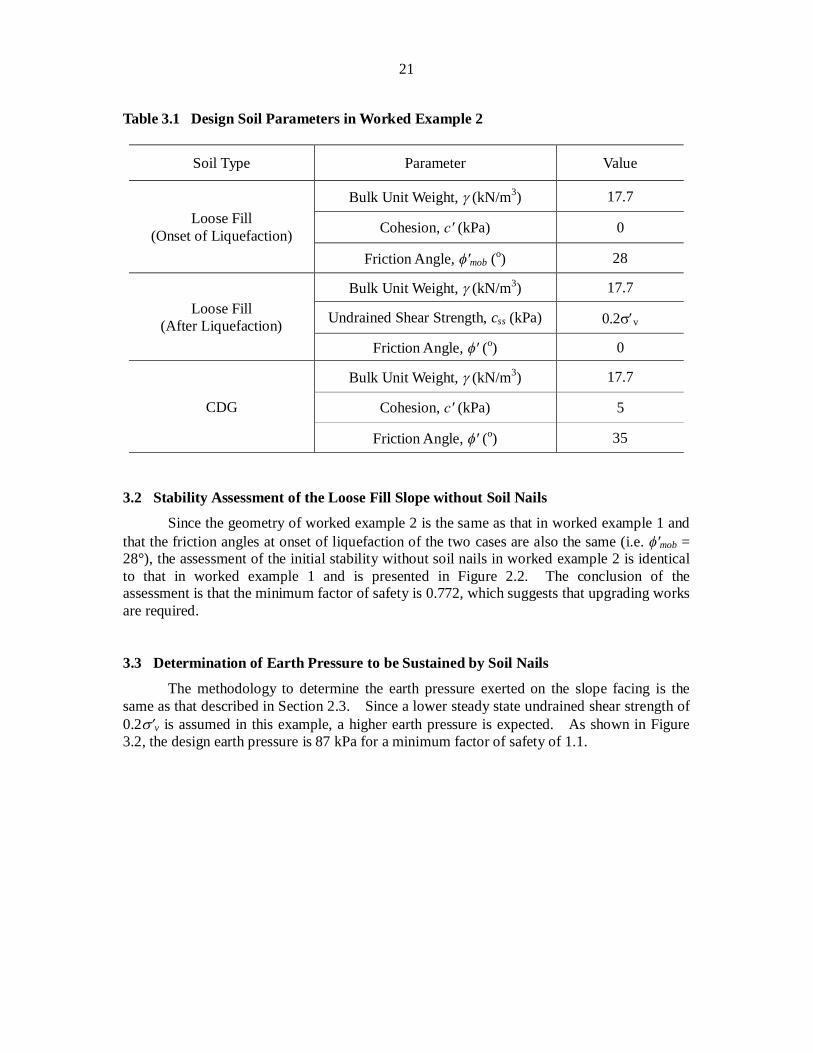
The methodology to determine the earth pressure exerted on the slope facing is the same as that described in Section 2.3. Since a lower steady state undrained shear strength of 0.2 v is assumed in this example, a higher earth pressure is expected. As shown in Figure 3.2, the design earth pressure is 87 kPa for a minimum factor of safety of 1.1.
22
Figure 3.2 Determination of Earth Pressure Exerted on Grillage Facing upon
Liquefaction in Worked Example 2 3.4 Design of Soil Nails
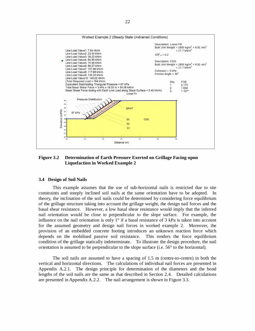
This example assumes that the use of sub-horizontal nails is restricted due to site constraints and steeply inclined soil nails at the same orientation have to be adopted. In theory, the inclination of the soil nails could be determined by considering force equilibrium of the grillage structure taking into account the grillage weight, the design nail forces and the basal shear resistance. However, a low basal shear resistance would imply that the inferred nail orientation would be close to perpendicular to the slope surface. For example, the influence on the nail orientation is only 1° if a basal resistance of 3 kPa is taken into account for the assumed geometry and design nail forces in worked example 2. Moreover, the provision of an embedded concrete footing introduces an unknown reaction force which depends on the mobilised passive soil resistance. This renders the force equilibrium condition of the grillage statically indeterminate. To illustrate the design procedure, the nail orientation is assumed to be perpendicular to the slope surface (i.e. 56° to the horizontal).
The soil nails are assumed to have a spacing of 1.5 m (centre-to-centre) in both the
vertical and horizontal directions. The calculations of individual nail forces are presented in Appendix A.2.1. The design principle for determination of the diameters and the bond lengths of the soil nails are the same as that described in Section 2.4. Detailed calculations are presented in Appendix A.2.2. The nail arrangement is shown in Figure 3.3.
Description: Loose Fill Bulk Unit Weight = 1800 kg/m3 × 9.81 m/s2
= 17.7 kN/m3 / v = 0.2
Description: CDG Bulk Unit Weight = 1800 kg/m3 × 9.81 m/s2
= 17.7 kN/m3 Cohesion = 5 kPa Friction Angle = 35o
23
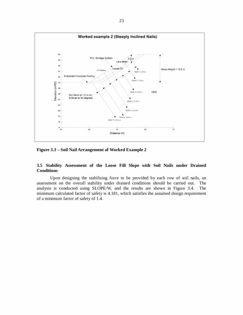
Figure 3.3 – Soil Nail Arrangement of Worked Example 2 3.5 Stability Assessment of the Loose Fill Slope with Soil Nails under Drained Conditions
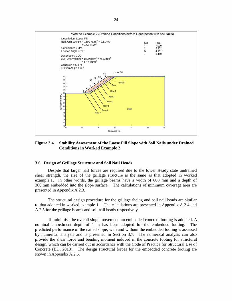
Upon designing the stabilising force to be provided by each row of soil nails, an assessment on the overall stability under drained conditions should be carried out. The analysis is conducted using SLOPE/W, and the results are shown in Figure 3.4. The minimum calculated factor of safety is 4.181, which satisfies the assumed design requirement of a minimum factor of safety of 1.4.
24
Figure 3.4 Stability Assessment of the Loose Fill Slope with Soil Nails under Drained
Conditions in Worked Example 2 3.6 Design of Grillage Structure and Soil Nail Heads
Despite that larger nail forces are required due to the lower steady state undrained shear strength, the size of the grillage structure is the same as that adopted in worked example 1. In other words, the grillage beams have a width of 600 mm and a depth of 300 mm embedded into the slope surface. The calculations of minimum coverage area are presented in Appendix A.2.3.
The structural design procedure for the grillage facing and soil nail heads are similar
to that adopted in worked example 1. The calculations are presented in Appendix A.2.4 and A.2.5 for the grillage beams and soil nail heads respectively.
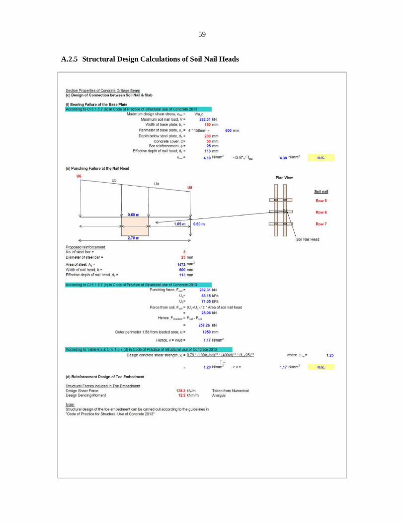
To minimise the overall slope movement, an embedded concrete footing is adopted. A
nominal embedment depth of 1 m has been adopted for the embedded footing. The predicted performance of the nailed slope, with and without the embedded footing is assessed by numerical analysis and is presented in Section 3.7. The numerical analysis can also provide the shear force and bending moment induced in the concrete footing for structural design, which can be carried out in accordance with the Code of Practice for Structural Use of Concrete (BD, 2013). The design structural forces for the embedded concrete footing are shown in Appendix A.2.5.
Description: CDG Bulk Unit Weight = 1800 kg/m3 × 9.81m/s2
= 17.7 kN/m3 Cohesion = 5 kPa Friction Angle = 35o
Description: Loose Fill Bulk Unit Weight = 1800 kg/m3 × 9.81m/s2
= 17.7 kN/m3 Cohesion = 0 kPa Friction Angle = 28o
25
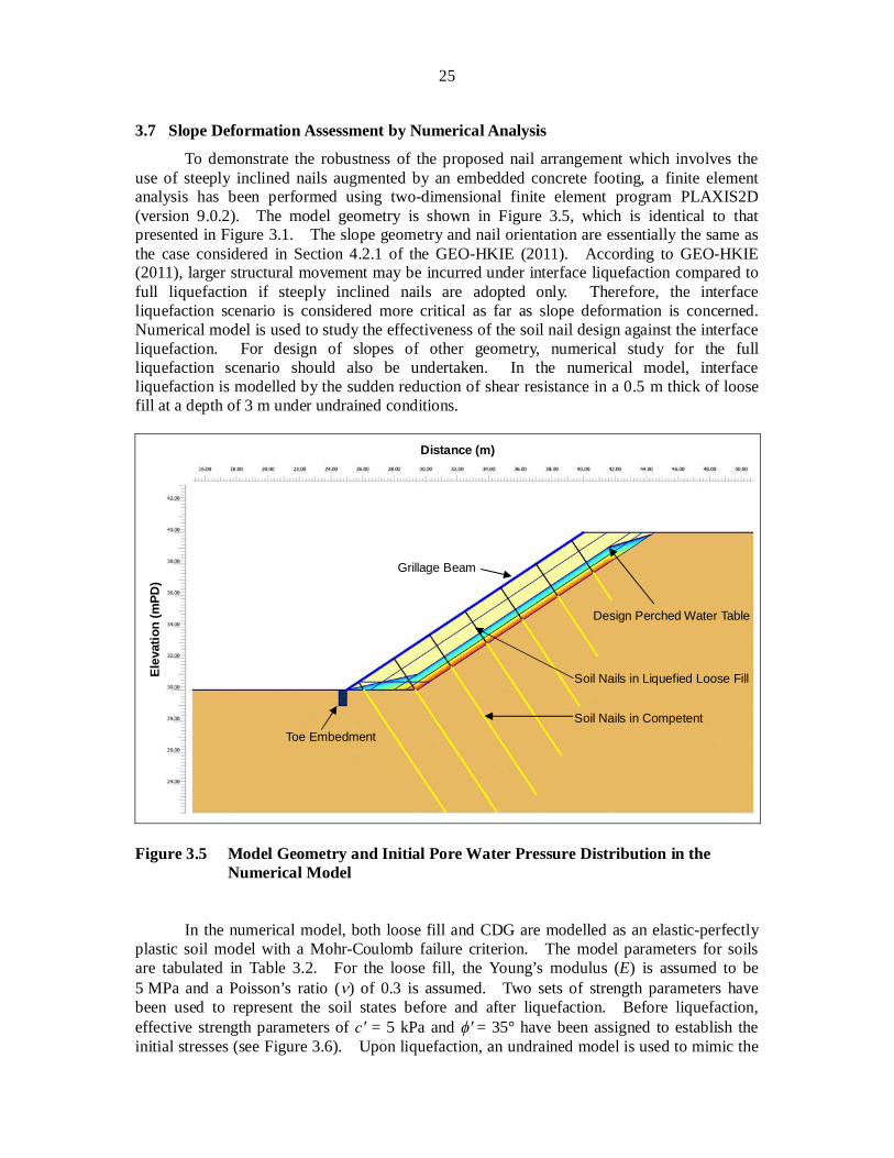
3.7 Slope Deformation Assessment by Numerical Analysis
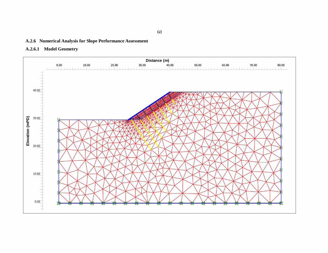
To demonstrate the robustness of the proposed nail arrangement which involves the use of steeply inclined nails augmented by an embedded concrete footing, a finite element analysis has been performed using two-dimensional finite element program PLAXIS2D (version 9.0.2). The model geometry is shown in Figure 3.5, which is identical to that presented in Figure 3.1. The slope geometry and nail orientation are essentially the same as the case considered in Section 4.2.1 of the GEO-HKIE (2011). According to GEO-HKIE (2011), larger structural movement may be incurred under interface liquefaction compared to full liquefaction if steeply inclined nails are adopted only. Therefore, the interface liquefaction scenario is considered more critical as far as slope deformation is concerned. Numerical model is used to study the effectiveness of the soil nail design against the interface liquefaction. For design of slopes of other geometry, numerical study for the full liquefaction scenario should also be undertaken. In the numerical model, interface liquefaction is modelled by the sudden reduction of shear resistance in a 0.5 m thick of loose fill at a depth of 3 m under undrained conditions.
Figure 3.5 Model Geometry and Initial Pore Water Pressure Distribution in the
Numerical Model
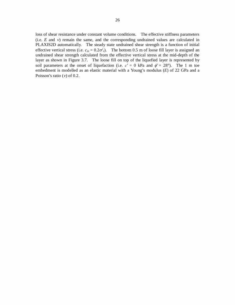
In the numerical model, both loose fill and CDG are modelled as an elastic-perfectly
plastic soil model with a Mohr-Coulomb failure criterion. The model parameters for soils are tabulated in Table 3.2. For the loose fill, the Young’s modulus (E) is assumed to be 5 MPa and a Poisson’s ratio ( ) of 0.3 is assumed. Two sets of strength parameters have been used to represent the soil states before and after liquefaction. Before liquefaction, effective strength parameters of = 5 kPa and = 35° have been assigned to establish the initial stresses (see Figure 3.6). Upon liquefaction, an undrained model is used to mimic the
Soil Nails in Competent
Soil Nails in Liquefied Loose Fill
Design Perched Water Table
Toe Embedment
Grillage Beam
Distance (m)
Ele
vatio
n (m
PD)
26
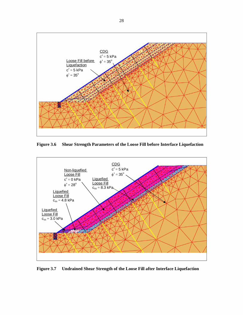
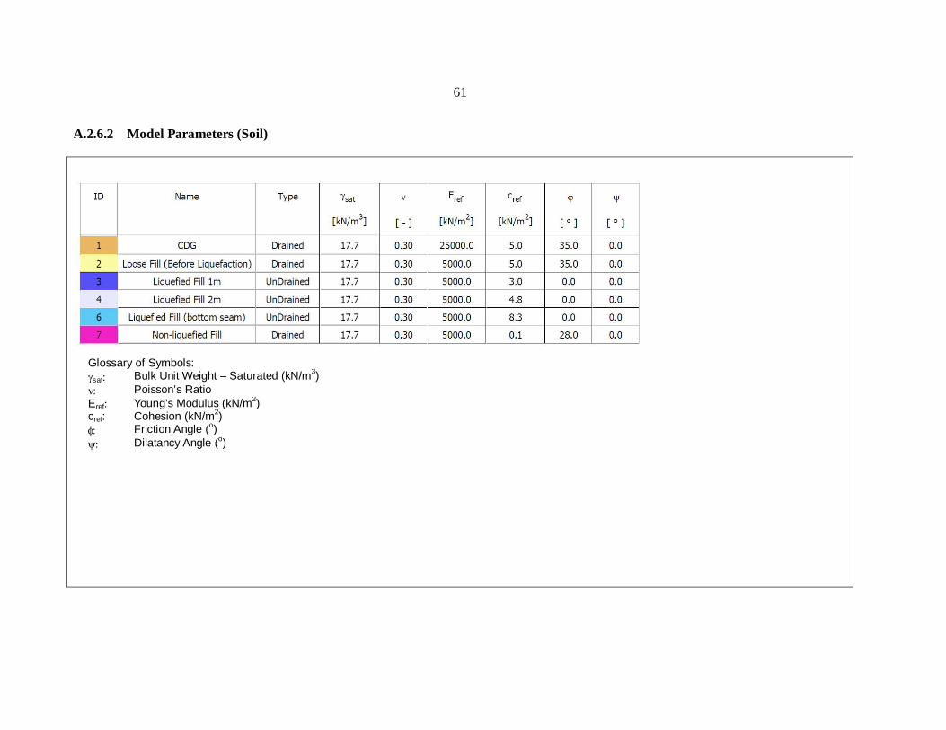
loss of shear resistance under constant volume conditions. The effective stiffness parameters (i.e. E and ) remain the same, and the corresponding undrained values are calculated in PLAXIS2D automatically. The steady state undrained shear strength is a function of initial effective vertical stress (i.e. css = 0.2 v). The bottom 0.5 m of loose fill layer is assigned an undrained shear strength calculated from the effective vertical stress at the mid-depth of the layer as shown in Figure 3.7. The loose fill on top of the liquefied layer is represented by soil parameters at the onset of liquefaction (i.e. = 0 kPa and = 28°). The 1 m toe embedment is modelled as an elastic material with a Young’s modulus (E) of 22 GPa and a Poisson’s ratio ( ) of 0.2.

27
Table 3.2 Model Parameters for Soils in the Numerical Analysis
Soil Type Model Type Parameter Input Value
Loose Fill (Before Liquefaction)
Elastic-Perfectly Plastic Model with
Mohr-Coulomb failure Criterion
(Drained)
Bulk Unit Weight, (kN/m3) 17.7
Cohesion, (kPa) 5
Friction Angle, (°) 35
Young’s Modulus, E (kPa) 5,000
Poisson’s Ratio, 0.3
Loose Fill (After Liquefaction)
Elastic-Perfectly Plastic Model with
Mohr-Coulomb Failure Criterion
(Undrained)
Bulk Unit Weight, (kN/m3) 17.7
Undrained Shear Strength, css (kPa) 3.0 to 8.3
*Young’s Modulus, E (kPa) 5,000
*Poisson’s Ratio, 0.3
Loose Fill (Non-liquefied)
Elastic-Perfectly Plastic Model with
Mohr-Coulomb Failure Criterion
(Drained)
Bulk Unit Weight, (kN/m3) 17.7
Cohesion, (kPa) 0
Friction Angle, (°) 28
Young’s Modulus, E (kPa) 5,000
CDG
Elastic-Perfectly Plastic Model with
Mohr-Coulomb Failure Criterion
(Drained)
Bulk Unit Weight, (kN/m3) 17.7
Cohesion, (kPa) 5
Friction Angle, (°) 35
Young’s Modulus, E (kPa) 25,000
Poisson’s Ratio, 0.3
Toe Embedment Elastic Model
Bulk Unit Weight, (kN/m3) 24
Young’s Modulus, E (kPa) 2.2 × 10⁷
Poisson’s Ratio, 0.2 *Notes: These are drained parameters. The corresponding undrained parameters are automatically calculated in PLAXIS2D.
28
Figure 3.6 Shear Strength Parameters of the Loose Fill before Interface Liquefaction
Figure 3.7 Undrained Shear Strength of the Loose Fill after Interface Liquefaction
Loose Fill before Liquefaction c = 5 kPa
= 35o
Liquefied Loose Fill css = 3.0 kPa
Liquefied Loose Fill css = 4.8 kPa
Liquefied Loose Fill css = 8.3 kPa
CDG c = 5 kPa
= 35o
CDG c = 5 kPa
= 35o Non-liquefied Loose Fill c = 0 kPa
= 28o
29
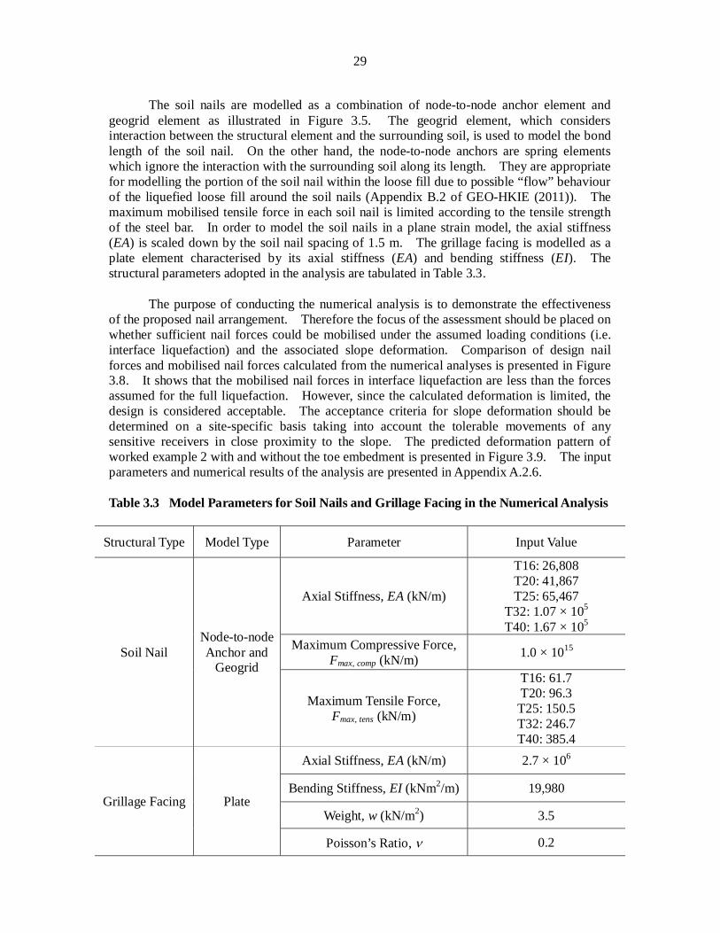
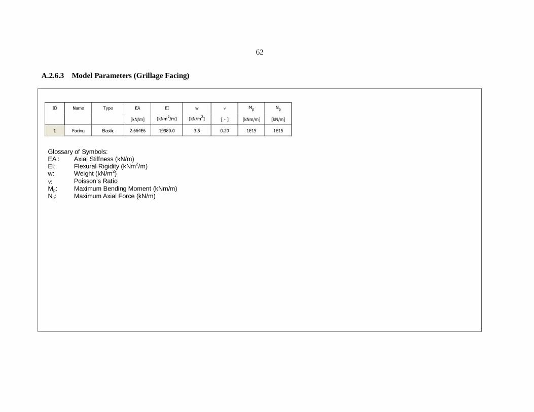
The soil nails are modelled as a combination of node-to-node anchor element and geogrid element as illustrated in Figure 3.5. The geogrid element, which considers interaction between the structural element and the surrounding soil, is used to model the bond length of the soil nail. On the other hand, the node-to-node anchors are spring elements which ignore the interaction with the surrounding soil along its length. They are appropriate for modelling the portion of the soil nail within the loose fill due to possible “flow” behaviour of the liquefied loose fill around the soil nails (Appendix B.2 of GEO-HKIE (2011)). The maximum mobilised tensile force in each soil nail is limited according to the tensile strength of the steel bar. In order to model the soil nails in a plane strain model, the axial stiffness (EA) is scaled down by the soil nail spacing of 1.5 m. The grillage facing is modelled as a plate element characterised by its axial stiffness (EA) and bending stiffness (EI). The structural parameters adopted in the analysis are tabulated in Table 3.3.
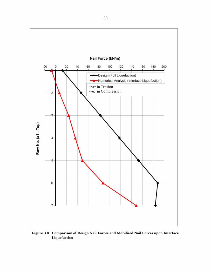
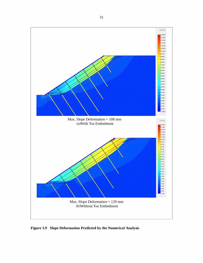
The purpose of conducting the numerical analysis is to demonstrate the effectiveness of the proposed nail arrangement. Therefore the focus of the assessment should be placed on whether sufficient nail forces could be mobilised under the assumed loading conditions (i.e. interface liquefaction) and the associated slope deformation. Comparison of design nail forces and mobilised nail forces calculated from the numerical analyses is presented in Figure 3.8. It shows that the mobilised nail forces in interface liquefaction are less than the forces assumed for the full liquefaction. However, since the calculated deformation is limited, the design is considered acceptable. The acceptance criteria for slope deformation should be determined on a site-specific basis taking into account the tolerable movements of any sensitive receivers in close proximity to the slope. The predicted deformation pattern of worked example 2 with and without the toe embedment is presented in Figure 3.9. The input parameters and numerical results of the analysis are presented in Appendix A.2.6. Table 3.3 Model Parameters for Soil Nails and Grillage Facing in the Numerical Analysis
Structural Type Model Type Parameter Input Value
Soil Nail Node-to-node Anchor and
Geogrid
Axial Stiffness, EA (kN/m)
T16: 26,808 T20: 41,867 T25: 65,467
T32: 1.07 × 10⁵ T40: 1.67 × 10⁵
Maximum Compressive Force, Fmax, comp (kN/m) 1.0 × 10¹⁵
Maximum Tensile Force, Fmax, tens (kN/m)
T16: 61.7 T20: 96.3 T25: 150.5 T32: 246.7 T40: 385.4
Grillage Facing Plate
Axial Stiffness, EA (kN/m) 2.7 × 10⁶
Bending Stiffness, EI (kNm2/m) 19,980
Weight, w (kN/m2) 3.5
Poisson’s Ratio, 0.2
30
Figure 3.8 Comparison of Design Nail Forces and Mobilised Nail Forces upon Interface
Liquefaction
+ve: in Tension -ve: in Compression
31
Figure 3.9 Slope Deformation Predicted by the Numerical Analysis
Max. Slope Deformation = 108 mm (a)With Toe Embedment
Max. Slope Deformation = 129 mm (b)Without Toe Embedment
32
4 Worked Example 3 – Design for Deep Fill Profile
4.1 Design Scenario and Assumptions
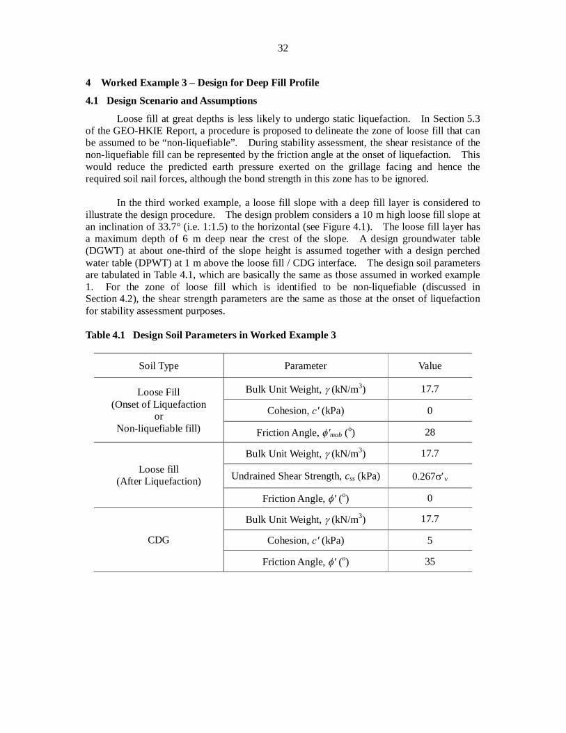
Loose fill at great depths is less likely to undergo static liquefaction. In Section 5.3 of the GEO-HKIE Report, a procedure is proposed to delineate the zone of loose fill that can be assumed to be “non-liquefiable”. During stability assessment, the shear resistance of the non-liquefiable fill can be represented by the friction angle at the onset of liquefaction. This would reduce the predicted earth pressure exerted on the grillage facing and hence the required soil nail forces, although the bond strength in this zone has to be ignored.
In the third worked example, a loose fill slope with a deep fill layer is considered to
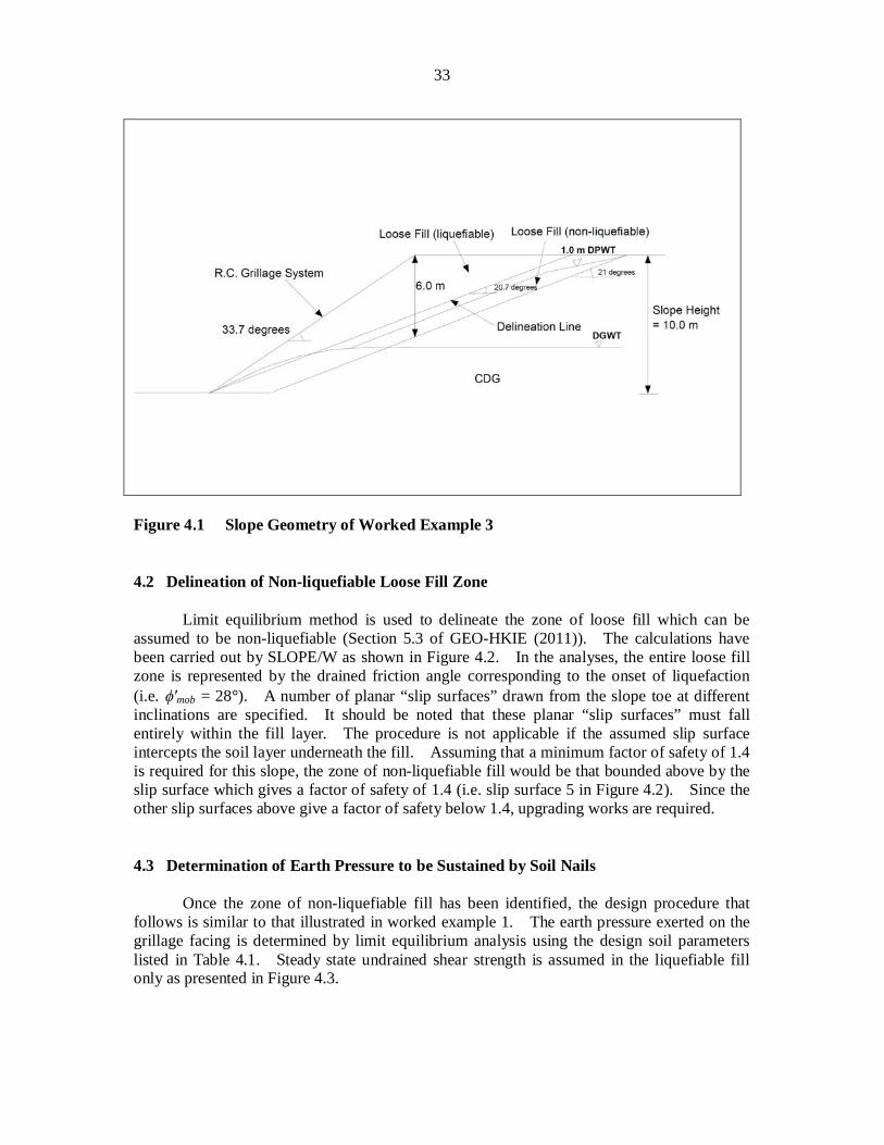
illustrate the design procedure. The design problem considers a 10 m high loose fill slope at an inclination of 33.7° (i.e. 1:1.5) to the horizontal (see Figure 4.1). The loose fill layer has a maximum depth of 6 m deep near the crest of the slope. A design groundwater table (DGWT) at about one-third of the slope height is assumed together with a design perched water table (DPWT) at 1 m above the loose fill / CDG interface. The design soil parameters are tabulated in Table 4.1, which are basically the same as those assumed in worked example 1. For the zone of loose fill which is identified to be non-liquefiable (discussed in Section 4.2), the shear strength parameters are the same as those at the onset of liquefaction for stability assessment purposes.
Table 4.1 Design Soil Parameters in Worked Example 3
Soil Type Parameter Value
Loose Fill (Onset of Liquefaction
or Non-liquefiable fill)
Bulk Unit Weight, (kN/m3) 17.7
Cohesion, (kPa) 0
Friction Angle, mob (o) 28
Loose fill (After Liquefaction)
Bulk Unit Weight, (kN/m3) 17.7
Undrained Shear Strength, css (kPa) 0.267 v
Friction Angle, (o) 0
CDG
Bulk Unit Weight, (kN/m3) 17.7
Cohesion, (kPa) 5
Friction Angle, (o) 35
33
Figure 4.1 Slope Geometry of Worked Example 3 4.2 Delineation of Non-liquefiable Loose Fill Zone
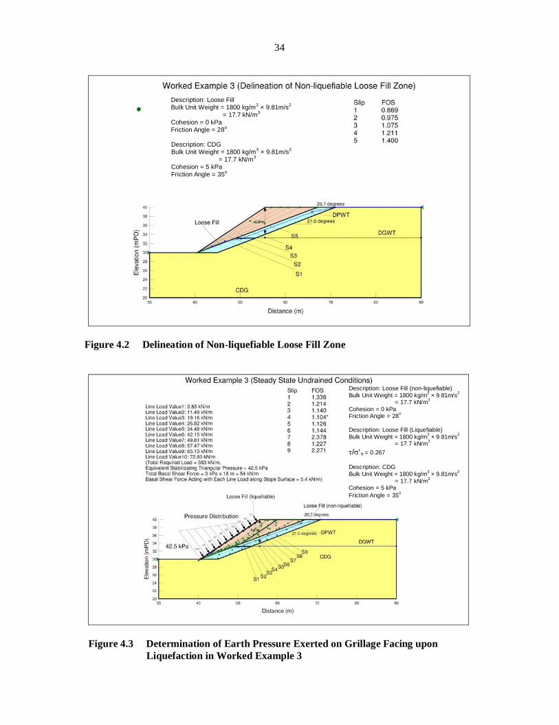
Limit equilibrium method is used to delineate the zone of loose fill which can be assumed to be non-liquefiable (Section 5.3 of GEO-HKIE (2011)). The calculations have been carried out by SLOPE/W as shown in Figure 4.2. In the analyses, the entire loose fill zone is represented by the drained friction angle corresponding to the onset of liquefaction (i.e. mob = 28°). A number of planar “slip surfaces” drawn from the slope toe at different inclinations are specified. It should be noted that these planar “slip surfaces” must fall entirely within the fill layer. The procedure is not applicable if the assumed slip surface intercepts the soil layer underneath the fill. Assuming that a minimum factor of safety of 1.4 is required for this slope, the zone of non-liquefiable fill would be that bounded above by the slip surface which gives a factor of safety of 1.4 (i.e. slip surface 5 in Figure 4.2). Since the other slip surfaces above give a factor of safety below 1.4, upgrading works are required. 4.3 Determination of Earth Pressure to be Sustained by Soil Nails
Once the zone of non-liquefiable fill has been identified, the design procedure that follows is similar to that illustrated in worked example 1. The earth pressure exerted on the grillage facing is determined by limit equilibrium analysis using the design soil parameters listed in Table 4.1. Steady state undrained shear strength is assumed in the liquefiable fill only as presented in Figure 4.3.
34
Figure 4.2 Delineation of Non-liquefiable Loose Fill Zone
Figure 4.3 Determination of Earth Pressure Exerted on Grillage Facing upon
Liquefaction in Worked Example 3
Description: CDG Bulk Unit Weight = 1800 kg/m3 × 9.81m/s2
= 17.7 kN/m3 Cohesion = 5 kPa Friction Angle = 35o
Description: Loose Fill Bulk Unit Weight = 1800 kg/m3 × 9.81m/s2
= 17.7 kN/m3 Cohesion = 0 kPa Friction Angle = 28o
Description: Loose Fill (non-liquefiable) Bulk Unit Weight = 1800 kg/m3 × 9.81m/s2
= 17.7 kN/m3 Cohesion = 0 kPa Friction Angle = 28o Description: Loose Fill (Liquefiable) Bulk Unit Weight = 1800 kg/m3 × 9.81m/s2
= 17.7 kN/m3 / v = 0.267
Description: CDG Bulk Unit Weight = 1800 kg/m3 × 9.81m/s2
= 17.7 kN/m3 Cohesion = 5 kPa Friction Angle = 35o
35
4.4 Design of Soil Nails
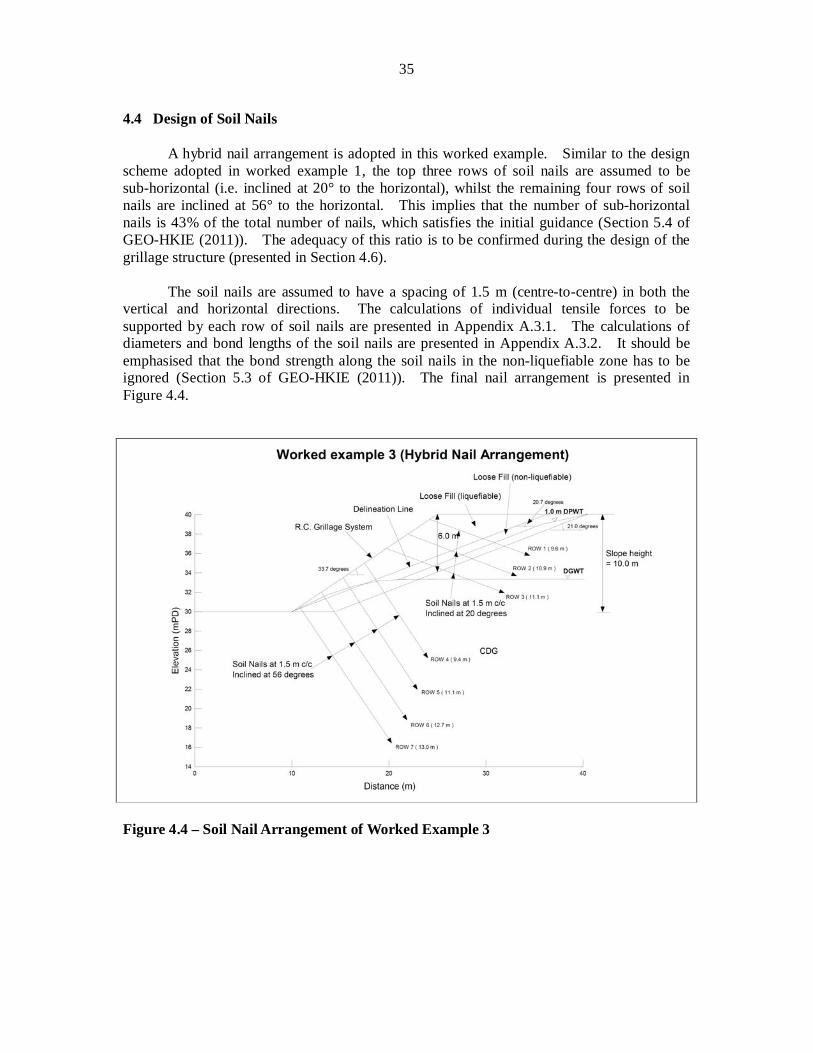
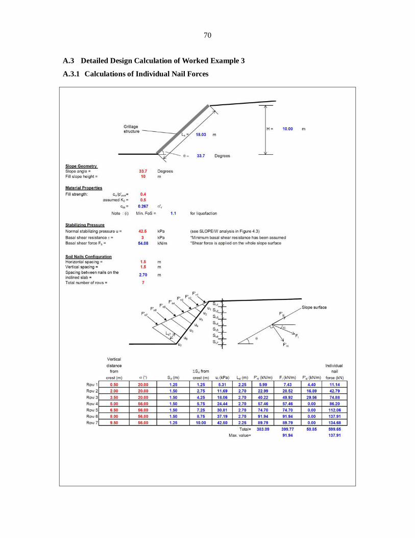
A hybrid nail arrangement is adopted in this worked example. Similar to the design scheme adopted in worked example 1, the top three rows of soil nails are assumed to be sub-horizontal (i.e. inclined at 20° to the horizontal), whilst the remaining four rows of soil nails are inclined at 56° to the horizontal. This implies that the number of sub-horizontal nails is 43% of the total number of nails, which satisfies the initial guidance (Section 5.4 of GEO-HKIE (2011)). The adequacy of this ratio is to be confirmed during the design of the grillage structure (presented in Section 4.6).
The soil nails are assumed to have a spacing of 1.5 m (centre-to-centre) in both the
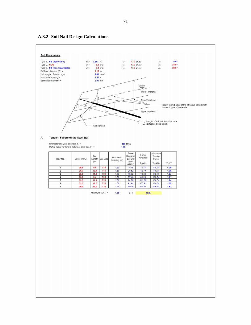
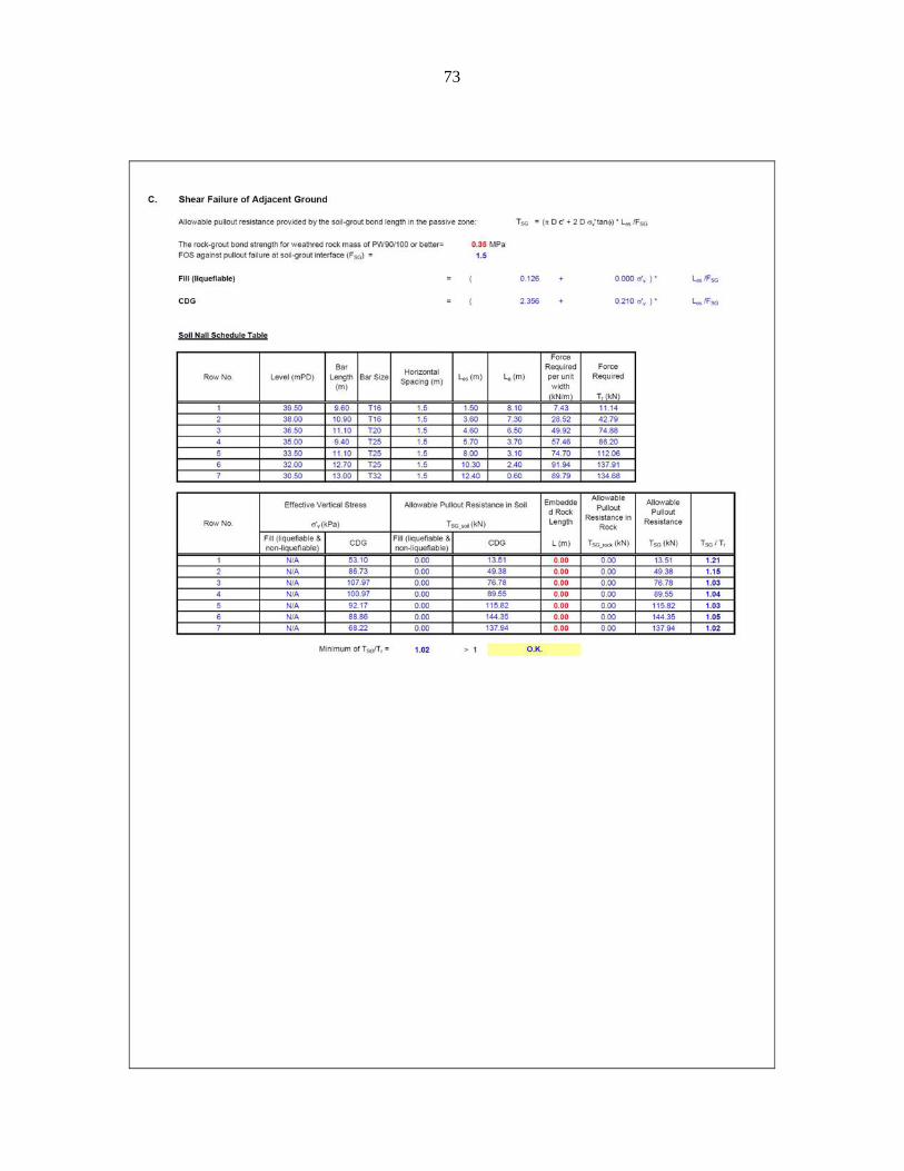
vertical and horizontal directions. The calculations of individual tensile forces to be supported by each row of soil nails are presented in Appendix A.3.1. The calculations of diameters and bond lengths of the soil nails are presented in Appendix A.3.2. It should be emphasised that the bond strength along the soil nails in the non-liquefiable zone has to be ignored (Section 5.3 of GEO-HKIE (2011)). The final nail arrangement is presented in Figure 4.4.
Figure 4.4 – Soil Nail Arrangement of Worked Example 3
36
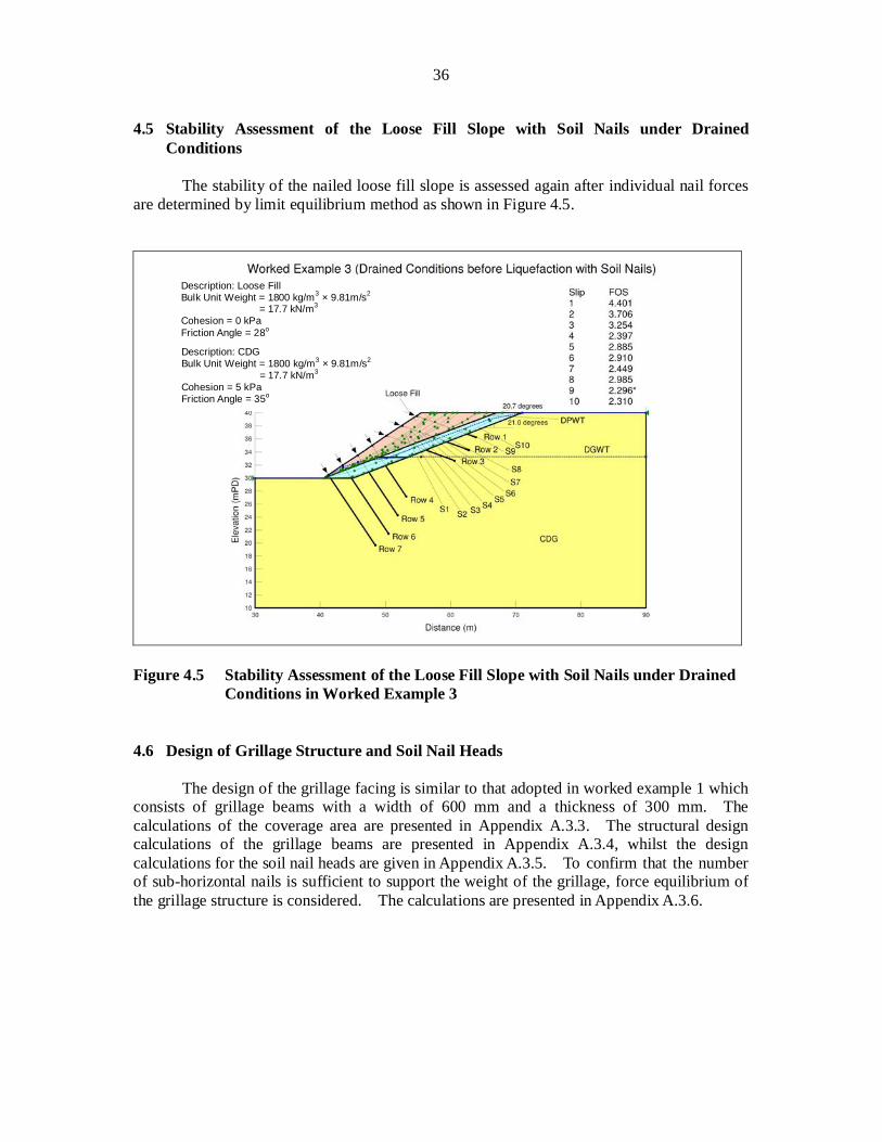
4.5 Stability Assessment of the Loose Fill Slope with Soil Nails under Drained Conditions
The stability of the nailed loose fill slope is assessed again after individual nail forces
are determined by limit equilibrium method as shown in Figure 4.5.
Figure 4.5 Stability Assessment of the Loose Fill Slope with Soil Nails under Drained
Conditions in Worked Example 3 4.6 Design of Grillage Structure and Soil Nail Heads
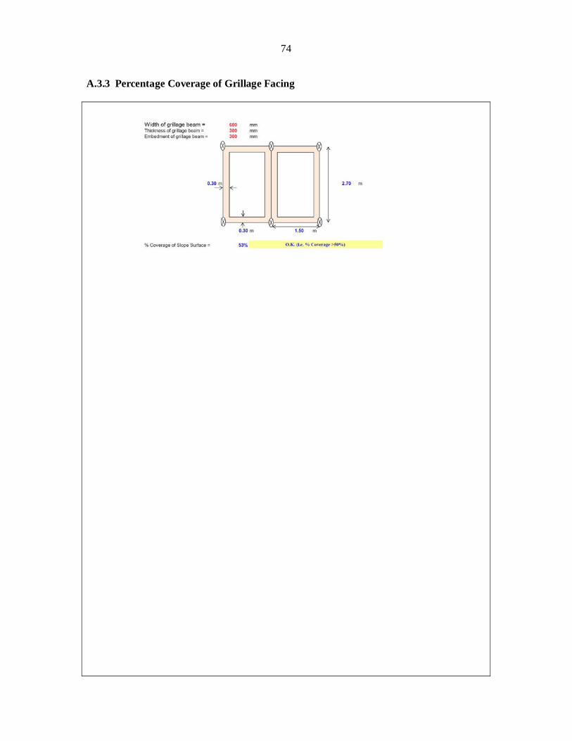
The design of the grillage facing is similar to that adopted in worked example 1 which
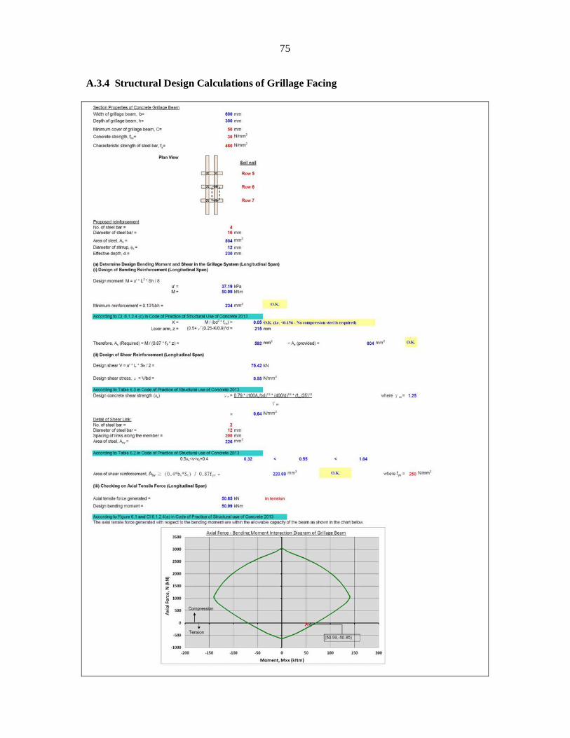
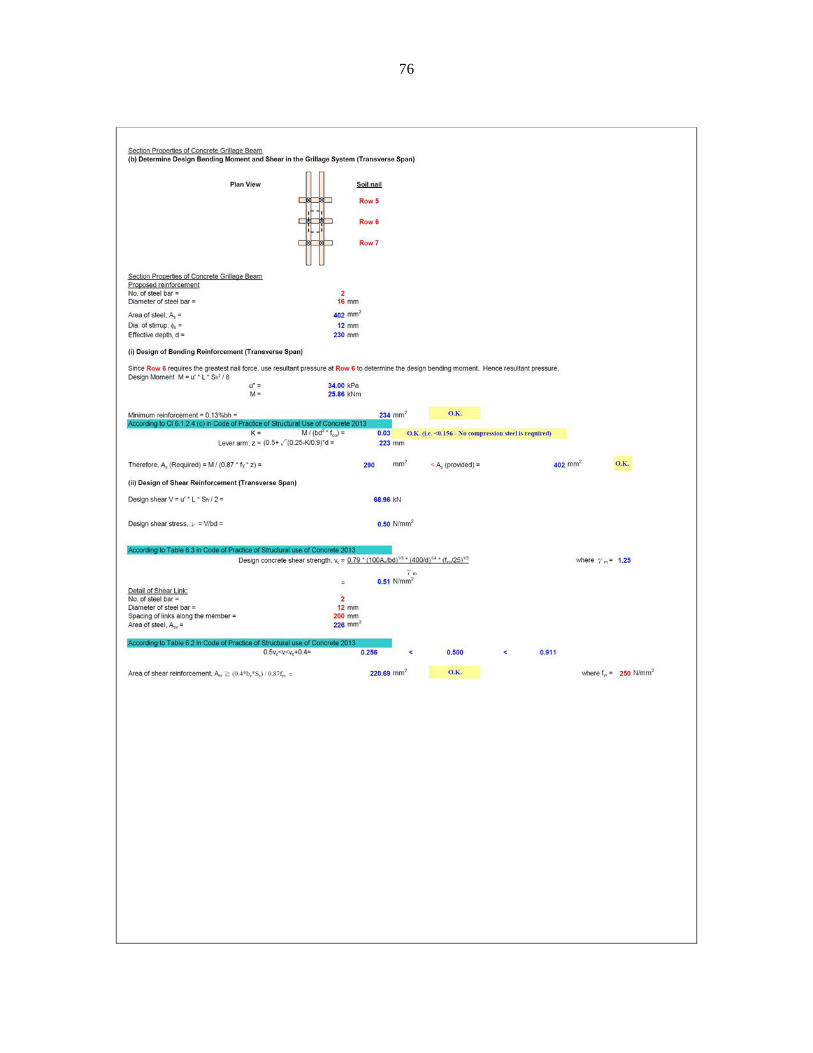
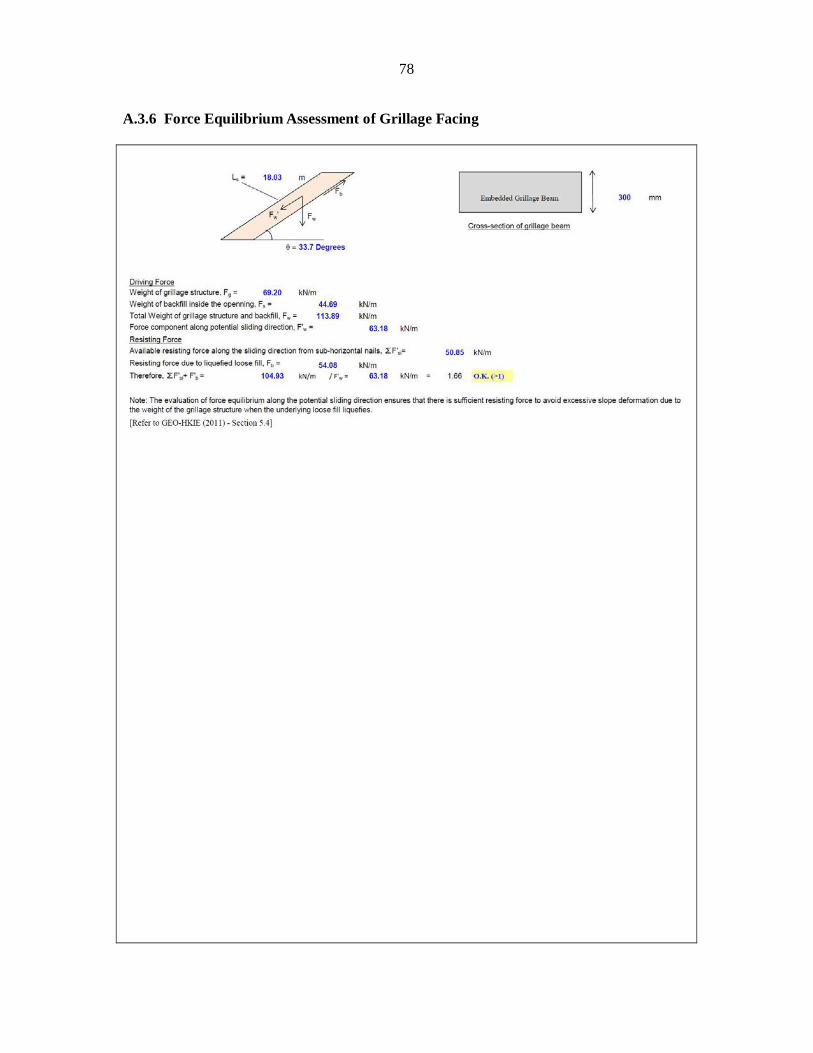
consists of grillage beams with a width of 600 mm and a thickness of 300 mm. The calculations of the coverage area are presented in Appendix A.3.3. The structural design calculations of the grillage beams are presented in Appendix A.3.4, whilst the design calculations for the soil nail heads are given in Appendix A.3.5. To confirm that the number of sub-horizontal nails is sufficient to support the weight of the grillage, force equilibrium of the grillage structure is considered. The calculations are presented in Appendix A.3.6.
Description: CDG Bulk Unit Weight = 1800 kg/m3 × 9.81m/s2
= 17.7 kN/m3 Cohesion = 5 kPa Friction Angle = 35o
Description: Loose Fill Bulk Unit Weight = 1800 kg/m3 × 9.81m/s2
= 17.7 kN/m3 Cohesion = 0 kPa Friction Angle = 28o
37
5 Discussion
The draft version of this report issued in April 2013 was circulated for comments among government departments and practitioners via HKIE-GD. The comments received have been incorporated in the final version of this report issued in October 2013. This Section highlights a few salient points which deserve special attention from designers. The comments and responses are attached in Appendix B.
5.1 Limit Equilibrium Analyses An important step in the design procedure is to determine the required stabilising
pressure on the slope facing using limit equilibrium method. The magnitude of a set of concentrated point loads distributed in a triangular shape representing the earth pressure can be determined. In theory, the triangular earth pressure should be modelled using as many point loads as possible. However, if too many point loads are used, the trial-and-error procedure to identify the required stabilising pressure would become impracticable. A simple case of a 10 m high slope has been considered to illustrate that 10 nos. of point loads are sufficient to limit the discrepancy to within 3% (see Comments and Responses on Page 89). For other design conditions, designers should make their own engineering judgement to determine the minimum number of point loads to represent the earth pressure. In addition, when the “Grid and Radius Method” is employed in slope stability analysis, the designer should bear in mind that the slip surface should embrace all the point loads exerted on the slope surface. If the critical slip surface does not embrace all the point loads on the slope surface, omission of some point loads may lead to underestimation of the loading condition.
5.2 Irregular Slope Profile
The purpose of this study is to demonstrate the implementation of the new recommendations given in the GEO-HKIE (2011) Report, therefore the slope geometry considered in the three worked examples is simplified. In reality, the slope profile may sometimes be irregular. In this case, the designer should use the actual slope profile to determine the earth pressure exerted on the facing structure. The earth pressure exerted on the facing structure should be assumed to be acting in the normal direction of the slope surface since very small shear stress can be mobilised along the interface between the facing and the loose fill. The small shear stress has already been taken into consideration by the assumed basal shear force. Therefore the earth pressure must be normal to the slope surface. When applying the stabilising point loads, one should consider if the proposed soil nail arrangement would be able to provide the assumed stabilising effects. For example the downward force exerted on the slope berm is unrealistic as no nail force would be mobilised in this direction, and stabilisation force applied on slope berm should be neglected for design purposes.
5.3 Delineation of Non-liquefiable Loose Fill Zone
The thickness of loose fill may vary. For the case where the thickness of the loose fill increases with height, similar to the one illustrated in Fig. 4.2, a linear slip surface can be
38
used to delineate the non-liquefiable zone. For the case where the thickness of loose fill decreases towards the slope crest, the non-liquefiable zone can be identified by assuming linear or bi-linear slip surfaces provided that these slip surfaces fall entirely within the loose fill zone (see Comments and Responses on Page 91). The liquefiable zone refers to the zone above the slip surface which has a minimum FOS of 1.4.
5.4 Structural Design of Grillage Structure
In the three worked examples presented in this report, structural design of the grillage was carried out by considering a segment of the grillage near the slope toe. For simplicity, the grillage beam is assumed to be simply supported, and is subjected to a uniformly distributed load. In theory, a continuous beam representing the entire facing structure should be used to determine the structural forces when a triangular pressure is exerted on the facing. A parametric study based on the soil nail arrangement of worked example 2 has been conducted to examine the possible discrepancies produced by the two different approaches described above (i.e., simply supported with uniformly distributed load and continuous beam with a triangular pressure). It is found that the calculated maximum bending moment is in general larger in the case of a simply supported beam with a uniformly distributed load for the conditions considered. The shear forces calculated from the two approaches are comparable in the worked example, with a percentage difference in the order of 1% in general. It can be concluded that simplifying the grillage as segments of simply supported beams is generally acceptable. However, designers should verify this approach on a case-by-case basis.
39
6 Conclusions Three worked examples have been prepared and presented to illustrate the
recommended procedure for designing soil nails to upgrade loose fill slopes. The design scenarios considered in these worked examples are relatively simple as the key objective is to demonstrate the use of hybrid nail arrangement which is recommended for enhanced system robustness. The adopted hybrid nail arrangement has been demonstrated through numerical modelling techniques to be sufficiently robust. For other proposed nail arrangements, e.g. similar to that adopted in worked example 2, designers are required to demonstrate the robustness of the proposed scheme. Particular focus should be placed on the nail force mobilisation mechanisms and the associated mobilised deformation.
40
7 References BD (2013). Code of Practice for Structural Use of Concrete. Buildings Department, Hong
Kong, 187 p. GCO (1984). Geotechnical Manual for Slopes. (2nd Edition). Geotechnical Control Office,
Civil Engineering Services Department, Hong Kong, 295 p. GEO (1993). Guide to Retaining Wall Design (Geoguide 1). Second Edition. Geotechnical
Engineering Office, Civil Engineering Department, Hong Kong, 258 p. GEO (2008). Guide to Soil Nail Design and Construction (Geoguide 7). Geotechnical
Engineering Office, Civil Engineering and Development Department, Hong Kong, 97 p.
GEO-HKIE (2011). Design of Soil Nails for Upgrading Loose Fill Slopes. Geotechnical
Engineering Office, Civil Engineering and Development Department, Hong Kong and The Hong Kong Institution of Engineers (Geotechnical Division), 96 p.
HKIE (2003). Soil Nails in Loose Fill Slopes. A Preliminary Study (Final Report). The Hong
Kong Institution of Engineers (Geotechnical Division), 88 p.
41
Appendix A
Detailed Design Calculations of Worked Examples
42
Contents Page No. Contents 41 A.1 Detailed Design Calculation of Worked Example 1 42 A.1.1 Calculations of Individual Nail Forces 42 A.1.2 Soil Nail Design Calculations 43 A.1.3 Percentage Coverage of Grillage Facing 46 A.1.4 Structural Design Calculations of Grillage Facing 47 A.1.5 Structural Design Calculations of Soil Nail Heads 49 A.1.6 Force Equilibrium Assessment of Grillage Facing 50 A.2 Detailed Design Calculation of Worked Example 2 51 A.2.1 Calculations of Individual Nail Forces 51 A.2.2 Soil Nail Design Calculations 52 A.2.3 Percentage Coverage of Grillage Facing 55 A.2.4 Structural Design Calculations of Grillage Facing 56 A.2.5 Structural Design Calculations of Soil Nail Heads 58 A.2.6 Numerical Analysis for Slope Performance Assessment 59 A.3 Detailed Design Calculation of Worked Example 3 69 A.3.1 Calculations of Individual Nail Forces 69 A.3.2 Soil Nail Design Calculations 70 A.3.3 Percentage Coverage of Grillage Facing 73 A.3.4 Structural Design Calculations of Grillage Facing 74 A.3.5 Structural Design Calculations of Soil Nail Heads 76 A.3.6 Force Equilibrium Assessment of Grillage Facing 77
43
A.1 Detailed Design Calculation of Worked Example 1
A.1.1 Calculations of Individual Nail Forces
44
A.1.2 Soil Nail Design Calculations
45
46
47
A.1.3 Percentage Coverage of Grillage Facing
48
A.1.4 Structural Design Calculations of Grillage Facing
49
50
A.1.5 Structural Design Calculations of Soil Nail Heads

51
A.1.6 Force Equilibrium Assessment of Grillage Facing
52
A.2 Detailed Design Calculation of Worked Example 2
A.2.1 Calculations of Individual Nail Forces
53
A.2.2 Soil Nail Design Calculations
54
55

56
A.2.3 Percentage Coverage of Grillage Facing
57
A.2.4 Structural Design Calculations of Grillage Facing
58
59
A.2.5 Structural Design Calculations of Soil Nail Heads
60
A.2.6 Numerical Analysis for Slope Performance Assessment
A.2.6.1 Model Geometry
Distance (m)
Ele
vatio
n (m
PD)
61
A.2.6.2 Model Parameters (Soil)
Glossary of Symbols: sat: Bulk Unit Weight – Saturated (kN/m3) Poisson’s Ratio
Eref: Young’s Modulus (kN/m2) cref: Cohesion (kN/m2)
Friction Angle (o) Dilatancy Angle (o)
62
A.2.6.3 Model Parameters (Grillage Facing)
Glossary of Symbols: EA : Axial Stiffness (kN/m) EI: Flexural Rigidity (kNm2/m) w: Weight (kN/m2)
Poisson’s Ratio Mp: Maximum Bending Moment (kNm/m) Np: Maximum Axial Force (kN/m)
63
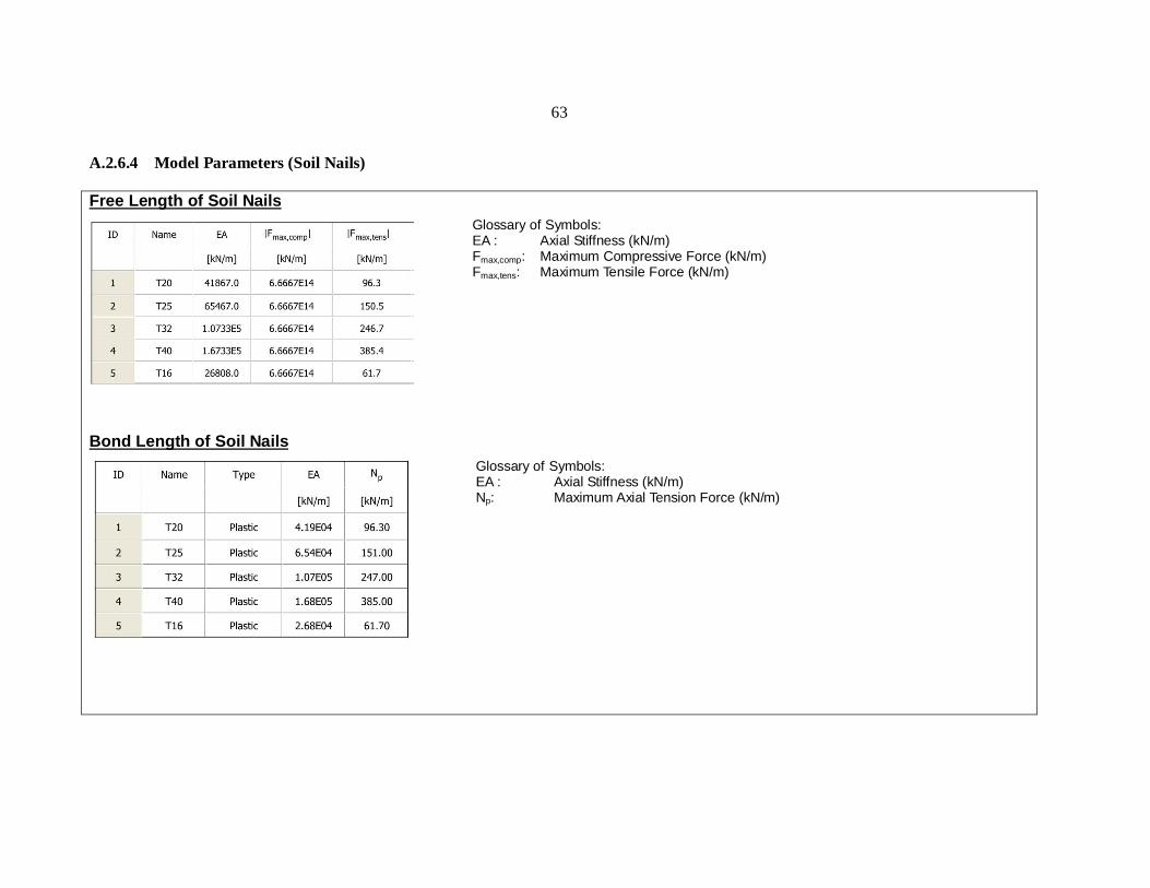
A.2.6.4 Model Parameters (Soil Nails) Free Length of Soil Nails
Bond Length of Soil Nails
Glossary of Symbols: EA : Axial Stiffness (kN/m) Fmax,comp: Maximum Compressive Force (kN/m) Fmax,tens: Maximum Tensile Force (kN/m)
Glossary of Symbols: EA : Axial Stiffness (kN/m) Np: Maximum Axial Tension Force (kN/m)
64
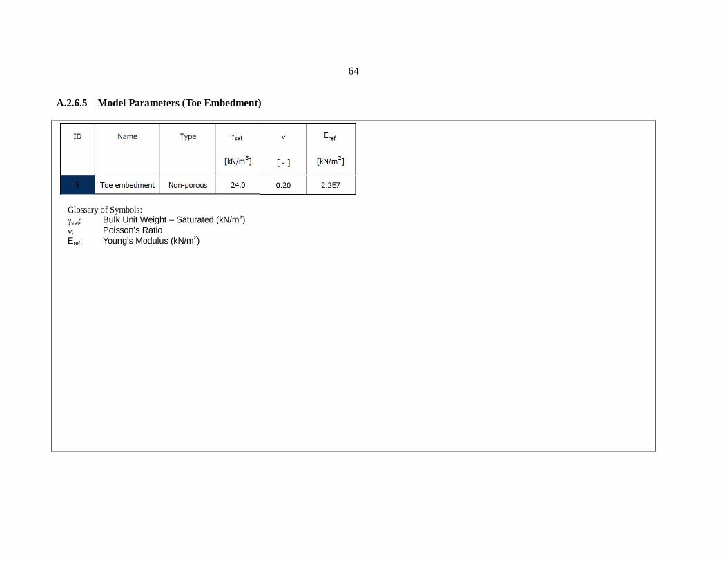
A.2.6.5 Model Parameters (Toe Embedment)
Glossary of Symbols: sat: Bulk Unit Weight – Saturated (kN/m3) Poisson’s Ratio
Eref: Young’s Modulus (kN/m2)
65
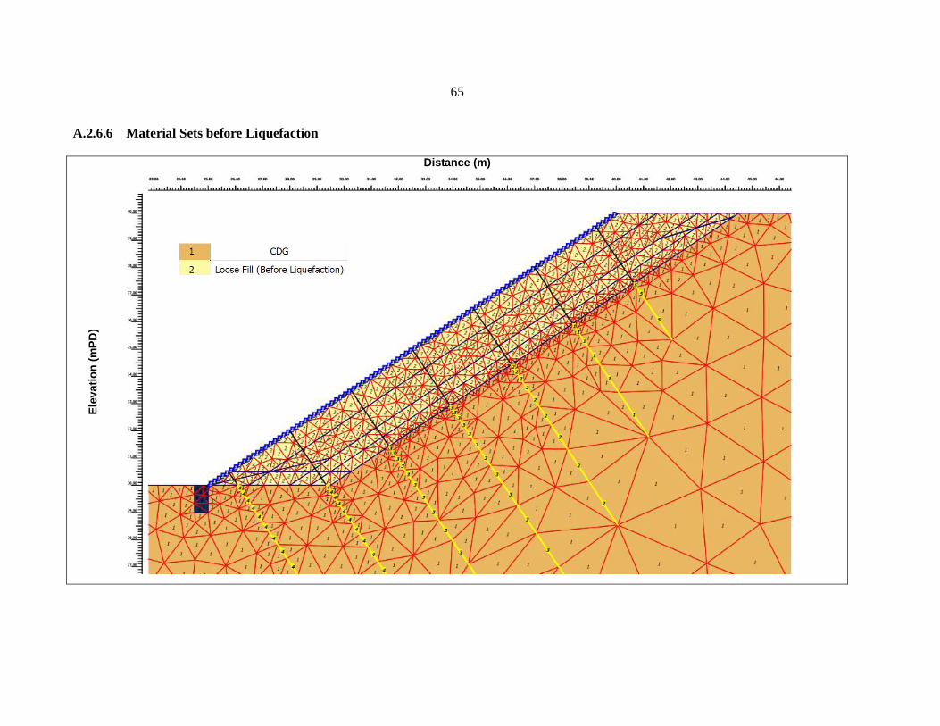
A.2.6.6 Material Sets before Liquefaction
Distance (m)
Ele
vatio
n (m
PD)
66
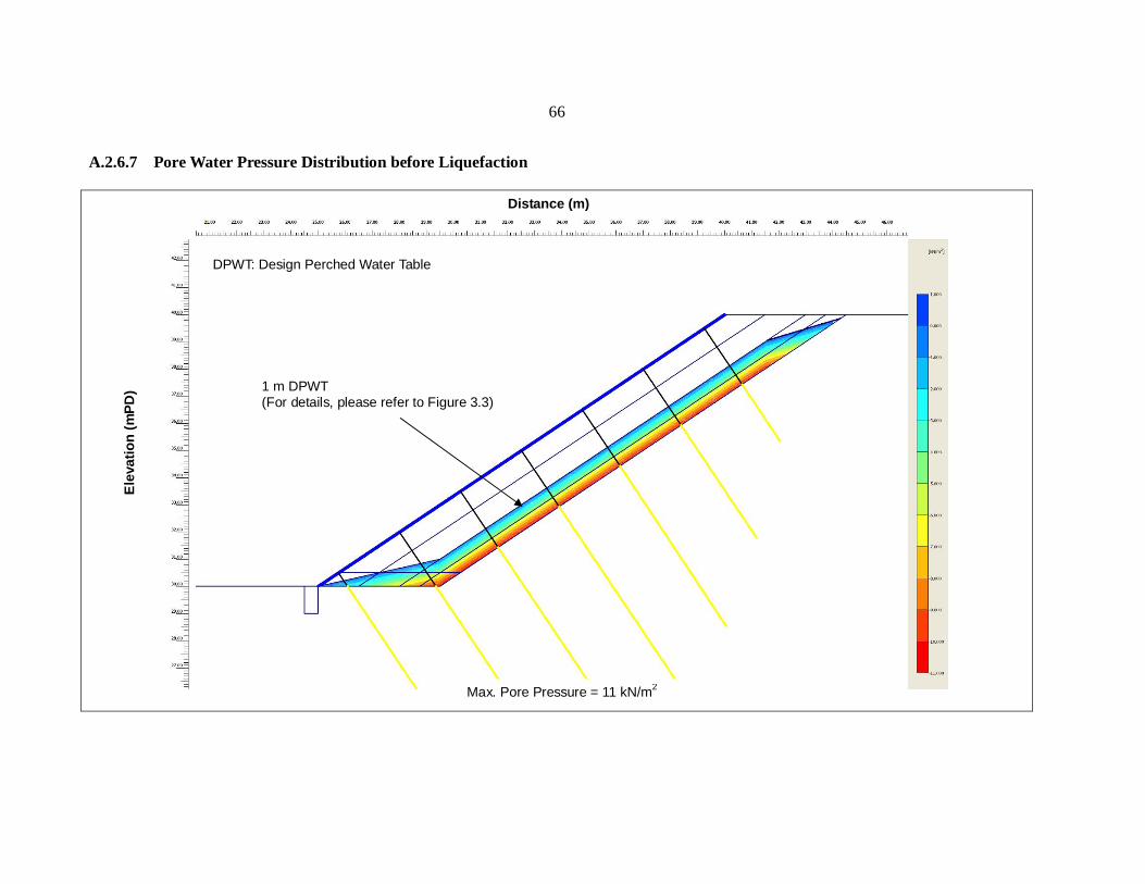
A.2.6.7 Pore Water Pressure Distribution before Liquefaction
Max. Pore Pressure = 11 kN/m2
1 m DPWT (For details, please refer to Figure 3.3)
DPWT: Design Perched Water Table
Distance (m)
Ele
vatio
n (m
PD)

67
A.2.6.8 Material Sets after Liquefaction
Distance (m)
Ele
vatio
n (m
PD) 5 Toe embedment
68
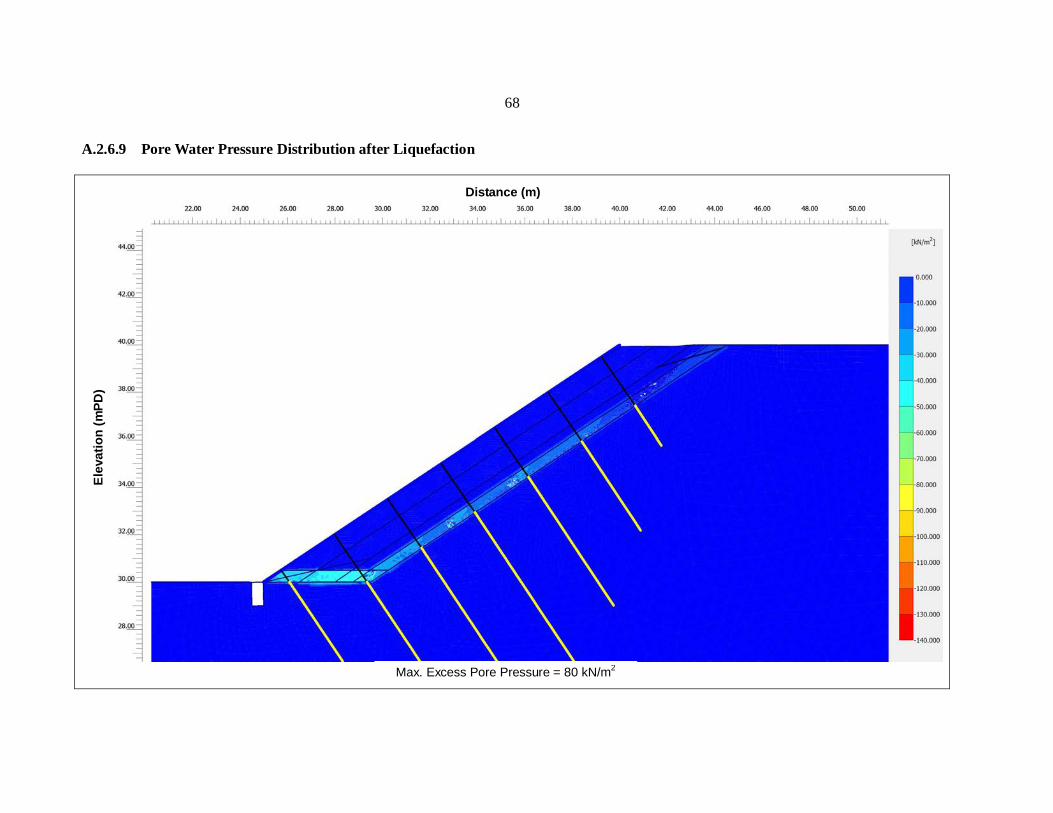
A.2.6.9 Pore Water Pressure Distribution after Liquefaction
Max. Excess Pore Pressure = 80 kN/m2
Distance (m)
Ele
vatio
n (m
PD)
69
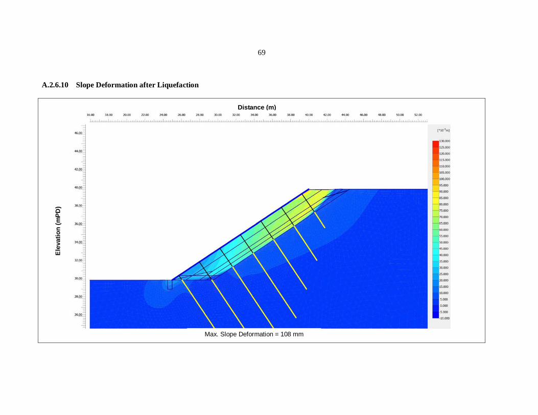
A.2.6.10 Slope Deformation after Liquefaction
Max. Slope Deformation = 108 mm
Distance (m)
Ele
vatio
n (m
PD)
70
A.3 Detailed Design Calculation of Worked Example 3
A.3.1 Calculations of Individual Nail Forces
71
A.3.2 Soil Nail Design Calculations

72
73
74
A.3.3 Percentage Coverage of Grillage Facing
75
A.3.4 Structural Design Calculations of Grillage Facing
76
77
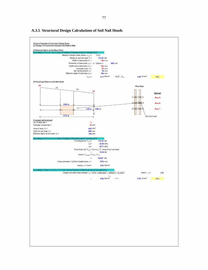
A.3.5 Structural Design Calculations of Soil Nail Heads
78
A.3.6 Force Equilibrium Assessment of Grillage Facing

79
Appendix B
Responses to Comments on Draft Report issued in April 2013

80
Design Illustrations on the Use of Soil Nails to Upgrade Loose Fill Slopes Responses to Comments
Comments Responses GEO/CEDD
1. Section 1.2(c) (P.10) According to Section 5.4 of GEO-HKIE Report, the sub-horizontal nails are provided to counter sliding failure due to interface liquefaction. The sentence “The number of sub-horizontal nails is considered appropriate if it is sufficient to support the weight of the grillage upon fill liquefaction” is misleading.
2. Section 3.6 (P.23)
The design calculation for the embedded concrete footing including the required reinforcement should be given in worked example 2.
1. According to Section 5.4 of GEO-HKIE (2011), the ratio of sub-horizontal nails to steeply inclined nails can be estimated by considering force equilibrium of the grillage facing. The number of sub-horizontal nails should be approximately 40% to 50% of the total number of soil nails to ensure sufficient sub-horizontal nails are present to counter sliding failure.
To avoid misunderstanding, the sentence “The number of sub-horizontal nails is considered appropriate if it is sufficient to support the weight of the grillage upon fill liquefaction” has been replaced by the above sentences.
2. The purpose of these worked examples is to illustrate the new design
recommendations highlighted in GEO-HKIE (2011). The structural design of the embedded footing can be carried out according to the guidelines in “Code of Practice for Structural Use of Concrete 2004 (Second Edition)” as for typical reinforced concrete structures. This is explained in Section 3.6 as follows: “The numerical analysis can also provide the shear force and bending moment induced in the concrete footing for structural design which can be carried out in accordance with the Code of Practice for Structural Use of Concrete (BD, 2004). The design structural forces for worked example 2 are shown in Appendix A.2.5.”
81
Comments Responses
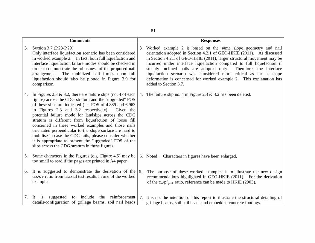
3. Section 3.7 (P.23-P.29) Only interface liquefaction scenario has been considered in worked example 2. In fact, both full liquefaction and interface liquefaction failure modes should be checked in order to demonstrate the robustness of the proposed nail arrangement. The mobilized nail forces upon full liquefaction should also be plotted in Figure 3.9 for comparison.
4. In Figures 2.3 & 3.2, there are failure slips (no. 4 of each figure) across the CDG stratum and the "upgraded" FOS of these slips are indicated (i.e. FOS of 4.889 and 6.963 in Figures 2.3 and 3.2 respectively). Given the potential failure mode for landslips across the CDG stratum is different from liquefaction of loose fill concerned in these worked examples and those nails orientated perpendicular to the slope surface are hard to mobilise in case the CDG fails, please consider whether it is appropriate to present the "upgraded" FOS of the slips across the CDG stratum in these figures.
5. Some characters in the Figures (e.g. Figure 4.5) may be
too small to read if the pages are printed in A4 paper. 6. It is suggested to demonstrate the derivation of the
css/s'v ratio from triaxial test results in one of the worked examples.
7. It is suggested to include the reinforcement details/configuration of grillage beams, soil nail heads
3. Worked example 2 is based on the same slope geometry and nail orientation adopted in Section 4.2.1 of GEO-HKIE (2011). As discussed in Section 4.2.1 of GEO-HKIE (2011), larger structural movement may be incurred under interface liquefaction compared to full liquefaction if steeply inclined nails are adopted only. Therefore, the interface liquefaction scenario was considered more critical as far as slope deformation is concerned for worked example 2. This explanation has added to Section 3.7.
4. The failure slip no. 4 in Figure 2.3 & 3.2 has been deleted.
5. Noted. Characters in figures have been enlarged.
6. The purpose of these worked examples is to illustrate the new design recommendations highlighted in GEO-HKIE (2011). For the derivation of the css/p’peak ratio, reference can be made to HKIE (2003).
7. It is not the intention of this report to illustrate the structural detailing of grillage beams, soil nail heads and embedded concrete footings.
82
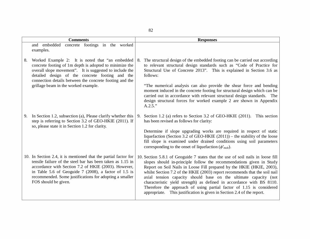
Comments Responses and embedded concrete footings in the worked examples.
8. Worked Example 2: It is noted that “an embedded concrete footing of 1m depth is adopted to minimize the overall slope movement”. It is suggested to include the detailed design of the concrete footing and the connection details between the concrete footing and the grillage beam in the worked example.
9. In Section 1.2, subsection (a), Please clarify whether this step is referring to Section 3.2 of GEO-HKIE (2011). If so, please state it in Section 1.2 for clarity.
10. In Section 2.4, it is mentioned that the partial factor for
tensile failure of the steel bar has been taken as 1.15 in accordance with Section 7.2 of HKIE (2003). However, in Table 5.6 of Geoguide 7 (2008), a factor of 1.5 is recommended. Some justifications for adopting a smaller FOS should be given.
8. The structural design of the embedded footing can be carried out according to relevant structural design standards such as “Code of Practice for Structural Use of Concrete 2013”. This is explained in Section 3.6 as follows:
“The numerical analysis can also provide the shear force and bending moment induced in the concrete footing for structural design which can be carried out in accordance with relevant structural design standards. The design structural forces for worked example 2 are shown in Appendix A.2.5.”
9. Section 1.2 (a) refers to Section 3.2 of GEO-HKIE (2011). This section
has been revised as follows for clarity:
Determine if slope upgrading works are required in respect of static liquefaction (Section 3.2 of GEO-HKIE (2011)) – the stability of the loose fill slope is examined under drained conditions using soil parameters corresponding to the onset of liquefaction ( mob).
10. Section 5.8.1 of Geoguide 7 states that the use of soil nails in loose fill slopes should in-principle follow the recommendations given in Study Report on Soil Nails in Loose Fill prepared by the HKIE (HKIE, 2003), whilst Section 7.2 of the HKIE (2003) report recommends that the soil nail axial tension capacity should base on the ultimate capacity (not characteristic yield strength) as defined in accordance with BS 8110. Therefore the approach of using partial factor of 1.15 is considered appropriate. This justification is given in Section 2.4 of the report.
83
Comments Responses
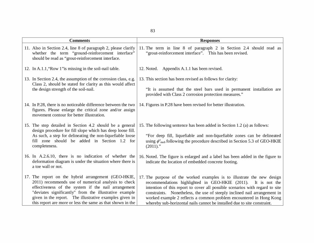
11. Also in Section 2.4, line 8 of paragraph 2, please clarify whether the term “ground-reinforcement interface” should be read as “grout-reinforcement interface.
12. In A.1.1,“Row 1”is missing in the soil-nail table. 13. In Section 2.4, the assumption of the corrosion class, e.g.
Class 2, should be stated for clarity as this would affect the design strength of the soil-nail.
14. In P.28, there is no noticeable difference between the two
figures. Please enlarge the critical zone and/or assign movement contour for better illustration.
15. The step detailed in Section 4.2 should be a general
design procedure for fill slope which has deep loose fill. As such, a step for delineating the non-liquefiable loose fill zone should be added in Section 1.2 for completeness.
16. In A.2.6.10, there is no indication of whether the
deformation diagram is under the situation where there is a toe wall or not.
17. The report on the hybrid arrangement (GEO-HKIE, 2011) recommends use of numerical analysis to check effectiveness of the system if the nail arrangement "deviates significantly" from the illustrative example given in the report. The illustrative examples given in this report are more or less the same as that shown in the
11. The term in line 8 of paragraph 2 in Section 2.4 should read as “grout-reinforcement interface”. This has been revised.
12. Noted. Appendix A.1.1 has been revised. 13. This section has been revised as follows for clarity:
“It is assumed that the steel bars used in permanent installation are provided with Class 2 corrosion protection measures.”
14. Figures in P.28 have been revised for better illustration. 15. The following sentence has been added in Section 1.2 (a) as follows:
“For deep fill, liquefiable and non-liquefiable zones can be delineated using mob following the procedure described in Section 5.3 of GEO-HKIE (2011).”
16. Noted. The figure is enlarged and a label has been added in the figure to indicate the location of embedded concrete footing.
17. The purpose of the worked examples is to illustrate the new design
recommendations highlighted in GEO-HKIE (2011). It is not the intention of this report to cover all possible scenarios with regard to site constraints. Nonetheless, the use of steeply inclined nail arrangement in worked example 2 reflects a common problem encountered in Hong Kong whereby sub-horizontal nails cannot be installed due to site constraint.
84
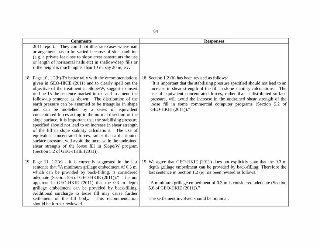
Comments Responses 2011 report. They could not illustrate cases where nail arrangement has to be varied because of site condition (e.g. a private lot close to slope crest constraints the use or length of horizontal nails etc) in shallow/deep fills or if the height is much higher than 10 m, say 20 m, etc.
18. Page 10, 1.2(b)-To better tally with the recommendations
given in GEO-HKIE (2011) and to clearly spell out the objective of the treatment in Slope/W, suggest to insert on line 15 the sentence marked in red and to amend the follow-up sentence as shown: The distribution of the earth pressure can be assumed to be triangular in shape and can be modelled by a series of equivalent concentrated forces acting in the normal direction of the slope surface. It is important that the stabilising pressure specified should not lead to an increase in shear strength of the fill in slope stability calculations. The use of equivalent concentrated forces, rather than a distributed surface pressure, will avoid the increase in the undrained shear strength of the loose fill in Slope/W program (Section 5.2 of GEO-HKIE (2011)).
19. Page 11, 1.2(e) - It is currently suggested in the last
sentence that "A minimum grillage embedment of 0.3 m, which can be provided by back-filling, is considered adequate (Section 5.6 of GEO-HKIE (2011))." It is not apparent in GEO-HKIE (2011) that the 0.3 m depth grillage embedment can be provided by back-filling. Additional surcharge to loose fill may cause further settlement of the fill body. This recommendation should be further reviewed.
18. Section 1.2 (b) has been revised as follows:
“It is important that the stabilising pressure specified should not lead to an increase in shear strength of the fill in slope stability calculations. The use of equivalent concentrated forces, rather than a distributed surface pressure, will avoid the increase in the undrained shear strength of the loose fill in some commercial computer programs (Section 5.2 of GEO-HKIE (2011)).”
19. We agree that GEO-HKIE (2011) does not explicitly state that the 0.3 m
depth grillage embedment can be provided by back-filling. Therefore the last sentence in Section 1.2 (e) has been revised as follows: “A minimum grillage embedment of 0.3 m is considered adequate (Section 5.6 of GEO-HKIE (2011)).” The settlement involved should be minimal.
85
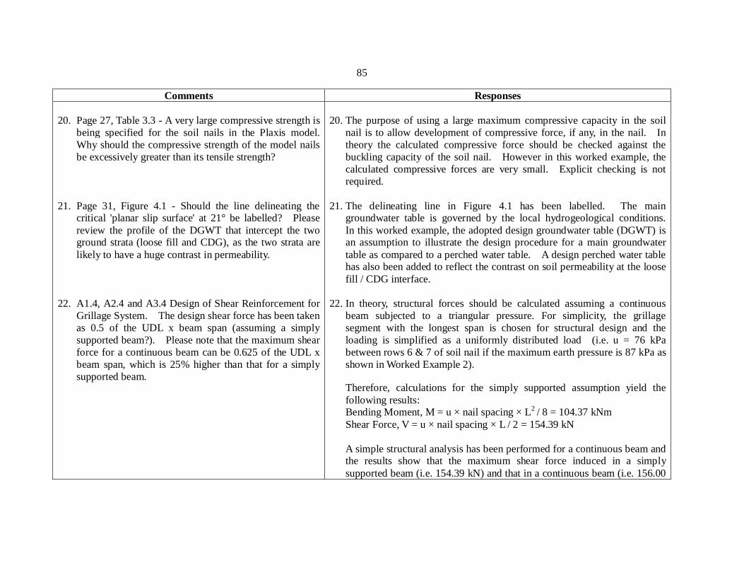
Comments Responses 20. Page 27, Table 3.3 - A very large compressive strength is
being specified for the soil nails in the Plaxis model. Why should the compressive strength of the model nails be excessively greater than its tensile strength?
21. Page 31, Figure 4.1 - Should the line delineating the
critical 'planar slip surface' at 21° be labelled? Please review the profile of the DGWT that intercept the two ground strata (loose fill and CDG), as the two strata are likely to have a huge contrast in permeability.
22. A1.4, A2.4 and A3.4 Design of Shear Reinforcement for
Grillage System. The design shear force has been taken as 0.5 of the UDL x beam span (assuming a simply supported beam?). Please note that the maximum shear force for a continuous beam can be 0.625 of the UDL x beam span, which is 25% higher than that for a simply supported beam.
20. The purpose of using a large maximum compressive capacity in the soil
nail is to allow development of compressive force, if any, in the nail. In theory the calculated compressive force should be checked against the buckling capacity of the soil nail. However in this worked example, the calculated compressive forces are very small. Explicit checking is not required.
21. The delineating line in Figure 4.1 has been labelled. The main groundwater table is governed by the local hydrogeological conditions. In this worked example, the adopted design groundwater table (DGWT) is an assumption to illustrate the design procedure for a main groundwater table as compared to a perched water table. A design perched water table has also been added to reflect the contrast on soil permeability at the loose fill / CDG interface.
22. In theory, structural forces should be calculated assuming a continuous beam subjected to a triangular pressure. For simplicity, the grillage segment with the longest span is chosen for structural design and the loading is simplified as a uniformly distributed load (i.e. u = 76 kPa between rows 6 & 7 of soil nail if the maximum earth pressure is 87 kPa as shown in Worked Example 2). Therefore, calculations for the simply supported assumption yield the following results: Bending Moment, M = u × nail spacing × L2 / 8 = 104.37 kNm Shear Force, V = u × nail spacing × L / 2 = 154.39 kN
A simple structural analysis has been performed for a continuous beam and the results show that the maximum shear force induced in a simply supported beam (i.e. 154.39 kN) and that in a continuous beam (i.e. 156.00
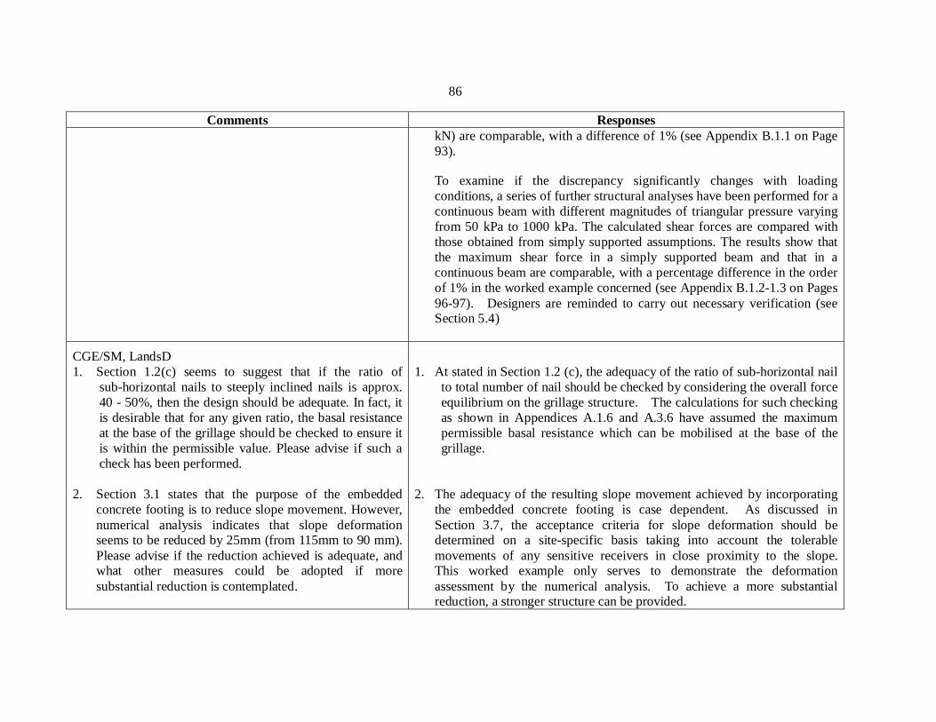
86
Comments Responses kN) are comparable, with a difference of 1% (see Appendix B.1.1 on Page 93). To examine if the discrepancy significantly changes with loading conditions, a series of further structural analyses have been performed for a continuous beam with different magnitudes of triangular pressure varying from 50 kPa to 1000 kPa. The calculated shear forces are compared with those obtained from simply supported assumptions. The results show that the maximum shear force in a simply supported beam and that in a continuous beam are comparable, with a percentage difference in the order of 1% in the worked example concerned (see Appendix B.1.2-1.3 on Pages 96-97). Designers are reminded to carry out necessary verification (see Section 5.4)
CGE/SM, LandsD 1. Section 1.2(c) seems to suggest that if the ratio of
sub-horizontal nails to steeply inclined nails is approx. 40 - 50%, then the design should be adequate. In fact, it is desirable that for any given ratio, the basal resistance at the base of the grillage should be checked to ensure it is within the permissible value. Please advise if such a check has been performed.
2. Section 3.1 states that the purpose of the embedded
concrete footing is to reduce slope movement. However, numerical analysis indicates that slope deformation seems to be reduced by 25mm (from 115mm to 90 mm). Please advise if the reduction achieved is adequate, and what other measures could be adopted if more substantial reduction is contemplated.
1. At stated in Section 1.2 (c), the adequacy of the ratio of sub-horizontal nail
to total number of nail should be checked by considering the overall force equilibrium on the grillage structure. The calculations for such checking as shown in Appendices A.1.6 and A.3.6 have assumed the maximum permissible basal resistance which can be mobilised at the base of the grillage.
2. The adequacy of the resulting slope movement achieved by incorporating
the embedded concrete footing is case dependent. As discussed in Section 3.7, the acceptance criteria for slope deformation should be determined on a site-specific basis taking into account the tolerable movements of any sensitive receivers in close proximity to the slope. This worked example only serves to demonstrate the deformation assessment by the numerical analysis. To achieve a more substantial reduction, a stronger structure can be provided.
87
Comments Responses 3. There does not appear to be any analysis of the effect of
the settlement of the grillage under its own weight on the integrity of the soil nail system, e.g. due to differential settlement induced at the nail/grillage connection. Please advise if such a check has been performed.
3. Additional bending moment could be resulted where differential settlement
occurs. However, since a uniform dimension of grillage beam is usually adopted, differential settlement is not likely. Thus, the suggested checking is considered not necessary in general. However, where certain conditions arise whereby differential settlements could occur, designers should duly consider the effects of differential settlements in the design.
CGE/HD 1. Section 2.1 Design Scenario and Assumptions On p.12
lines 7-10 – We note from Worked Example 1 that the design soil parameters are assumed to be determined from the site-specific laboratory testing. It would be desirable to provide relevant guidance / examples on how to interpret site-specific laboratory testing results.
2. Section 2.4 Design of Soil Nails On p.15 lines 1-3 – It is noted that three rows of sub-horizontal nails at 20o to horizontal and four rows of nails at 56o to the horizontal are adopted in Worked Example 1. If the ratio of sub-horizontal nails to steeply inclined nails complies with the recommendation in Section 5.4 of the GEO-HKIE Report, could the alternative nail patterns (i.e. nail inclinations deviated from the above) be adopted in the design without the need to conduct numerical analyses?
3. Section 3.1 Design Scenario and Assumptions
On p.19 lines 8-9 – It is mentioned that the roles of the embedded concrete footing is to reduce slope movement
1. The purpose of these worked examples is to illustrate the new design
recommendations highlighted in GEO-HKIE (2011). For the derivation of the css/p’peak ratio, reference can be made to HKIE (2003).
2. According to Section 5.4 of GEO-HKIE (2011), if an alternative nail
arrangement which deviates significantly from that illustrated in Figure 4.2c is intended to suit actual site conditions, the designer should demonstrate the effectiveness and robustness of the proposed nail arrangement using numerical analyses. If a hybrid nail arrangement is adopted following Section 5.4 of GEO-HKIE (2011), numerical analysis to demonstrate the robustness of the proposed scheme is considered not necessary. However, it should be noted that the required number of sub-horizontal nails and their inclinations are governed by the slope geometry, soil properties, and groundwater conditions. This should be checked by considering the force equilibrium of the facing as described in Section 5.4 of GEO-HKIE (2011).
3. The purpose of these worked examples is to illustrate the new design
recommendations highlighted in GEO-HKIE (2011). The structural design of the embedded footing can be carried out according to relevant
88
Comments Responses upon fill liquefaction. It would be useful to include a worked example to illustrate the footing design based on the results of numerical analyses described in Section 3.7.
4. Appendix A Detailed Design Calculation of Worked Examples The following editorial errors are noted: i) On p.66, the title of Worked Example A.3 “A.3 Detailed Design Calculation of Worked Example 3” should be inserted. ii) The page numbers for Worked Example A.3 are missing.
structural design standards such as “Code of Practice for Structural Use of Concrete 2013”. This is explained in Section 3.6 as follows:
“The numerical analysis can also provide the shear force and bending moment induced in the concrete footing for the structural design which can be carried out in accordance with relevant structural design standards. The design structural forces for worked example 2 are shown in Appendix A.2.5.”
4. Noted. The corresponding sections have been revised.
Ir Leslie Swann of Jacobs (HKIE member)
1. Section 1.2 (b) – Modelling of stabilizing pressure by equivalent concentrated forces It seems that modelling of the stabilizing earth pressure to be sustained by the soil nails by using a set of discrete point loads can lead to have great variance of FOS if the “Grid and Radius Method” in Slope/W is employed in the limit equilibrium analysis.
We have conducted a preliminary study using a slope geometry and design parameters similar to Figure 2.1 and Table 2.1 of the above Report respectively, as
1. One possible reason for the large variance in FOS when the “Grid and Radius Method” is employed is that the critical slip surface may not intercept the slope surface at the slope toe and therefore have omitted the contribution from some of the point loads near the toe. The figures provided are not sufficiently clear to identify the location where the critical slip surface intercepts the slope surface. To illustrate the potential problems associated with the use of the “Grid and Radius Method”, a set of Slope/W analyses with the same assumptions adopted by the reviewer have been conducted. The four analyses considered different numbers of point loads (i.e., 10, 20, 30, and 60) and the FOS was calculated using the “Grid and Radius Method”.

89
Comments Responses presented in the enclosed Figs 1 to 4 (see Appendix B.2 on Pages 98 to 101). In this model, we have calculated the FOS based on different numbers of point loads (10, 20, 30 and 60). The results indicate that the FOS can range from 0.991 to 1.122 with the same equivalent stabilizing triangular pressure of 60kPa when comparing the same slip surface.
We have also compared the case of 10 nos. of point load as shown in Figs 1 and 5 (see Appendix B.2 on Pages 98 to 102), the Umax had increased from 60kPa to 72kPa if FOS of 1.1 to be required. As a result, the length of the soil nail would increase about 10% as presented in Figure 6 (see Appendix B.2 on Page 103). As such, it is advisable to provide more guidance or recommendation on the adoption of number of point to be used in the stability analysis in order to provide a more cost-effectiveness design.
The results of the analysis with 60 point loads are presented in Appendix B.3 on Page 106. It can be seen that four no. of point loads have been omitted in the calculations as the critical slip surface intercepts the slope surface above these points. The omitted stabilising force is 76.66 kN/m and the resulting FOS is 1.176. The results of the other cases are summarised in the table shown below.
Case No. of omitted
point loads Total omitted point loads
FOS
60 point loads 4 76.66 kN/m 1.176 30 point loads 2 76.66 kN/m 1.175 20 point loads 1 57.99 kN/m 1.246 10 point loads 1 113 kN/m 1.056
The results suggest that FOS decreases as the magnitude of total omitted point loads increases. As the assumed distribution of the earth pressure is triangular, the omitted point loads near the slope toe will have larger effect on FOS than that of other locations. Although the omission of point loads errs on the conservative side, it does not reflect the reality that the facing structure is monolithic.
A better way to investigate the effect of numbers of point loads on FOS is to specify a slip surface which embraces all the point loads exerted on the slope surface. Following the same geometry and soil parameters in Figure 2.1 and Table 2.1 in the Report - “Design Illustrations on the Use of Soil Nails to Upgrade Loose Fill Slopes”, 10-, 20-, 30-, and 60-point loads cases have been compared. The resulting FOSs are 1.102, 1.105, 1.078, and 1.08, respectively. The small variance is considered acceptable.
In theory, the triangular earth pressure should be modelled using as many
90
Comments Responses 2. Section 1.2 (b) – Modelling of stabilizing pressure by
equivalent concentrated forces
It is mentioned that the distribution of the earth pressure can be modelled by a series of equivalent concentrated forces acting in the normal direction of the slope surface. In fact, the slope profile is usually non-uniform or comprises of several batters and designers may opt for adopting a single average slope angle to calculate the direction of the earth pressure for all concentrated forces. A comparison was done (see Figs 7 and 8 in Appendix B.2 on Pages 104 and 105) to review the effect of the orientation of the point load to the calculation of the FOS. It was found that adopting the average slope angle could lead to significant variance in the FOS calculation (Slip No. #3). It may worth mentioning this issue in the report as a reminder to the practitioners when conducting modelling.
3. Section 2.6 – Design of the Grillage Structure and Soil Nail Heads
According to Section 2.6 and the Structural Design Calculations of Grillage Facing for the examples, it is
point loads as possible. However, if many point loads are used, the trial-and-error procedure to identify the required stabilising pressure would become impractical. In the case considered, it has been demonstrated that 10 nos. of point loads are sufficient to limit the error to within 3%. For other design conditions, designers should make their own engineering judgement to determine the minimum number of point loads to represent the earth pressure.
2. The earth pressure exerted on the facing structure is assumed to be acting
in the normal direction of the slope surface since very small shear stress can be mobilised along the interface between the facing and the loose fill. This small shear stress has already been taken into consideration by the assumed basal shear force. Therefore the earth pressure must be normal to the slope surface. When applying the stabilising point loads, one should consider if the proposed soil nail arrangement would be able to provide the assumed stabilising effects. For example the downward force exerted on the slope berm is unrealistic as no nail force would be mobilised in this direction, and stabilisation force exerted on slope berm should be neglected for design purpose.
3. The suggestion to model the continuous grillage beam as “simply supported” is for simplicity. It is acceptable to analyze the entire grillage beam as a continuous structure to come up with an optimized design.
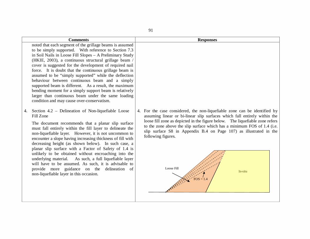
91
Comments Responses noted that each segment of the grillage beams is assumed to be simply supported. With reference to Section 7.3 in Soil Nails in Loose Fill Slopes – A Preliminary Study (HKIE, 2003), a continuous structural grillage beam / cover is suggested for the development of required nail force. It is doubt that the continuous grillage beam is assumed to be “simply supported” while the deflection behaviour between continuous beam and a simply supported beam is different. As a result, the maximum bending moment for a simply support beam is relatively larger than continuous beam under the same loading condition and may cause over-conservatism.
4. Section 4.2 – Delineation of Non-liquefiable Loose Fill Zone The document recommends that a planar slip surface must fall entirely within the fill layer to delineate the non-liquefiable layer. However, it is not uncommon to encounter a slope having increasing thickness of fill with decreasing height (as shown below). In such case, a planar slip surface with a Factor of Safety of 1.4 is unlikely to be obtained without encroaching into the underlying material. As such, a full liquefiable layer will have to be assumed. As such, it is advisable to provide more guidance on the delineation of non-liquefiable layer in this occasion.
4. For the case considered, the non-liquefiable zone can be identified by assuming linear or bi-linear slip surfaces which fall entirely within the loose fill zone as depicted in the figure below. The liquefiable zone refers to the zone above the slip surface which has a minimum FOS of 1.4 (i.e. slip surface S8 in Appendix B.4 on Page 107) as illustrated in the following figures.
Loose Fill In-situ
FOS = 1.4
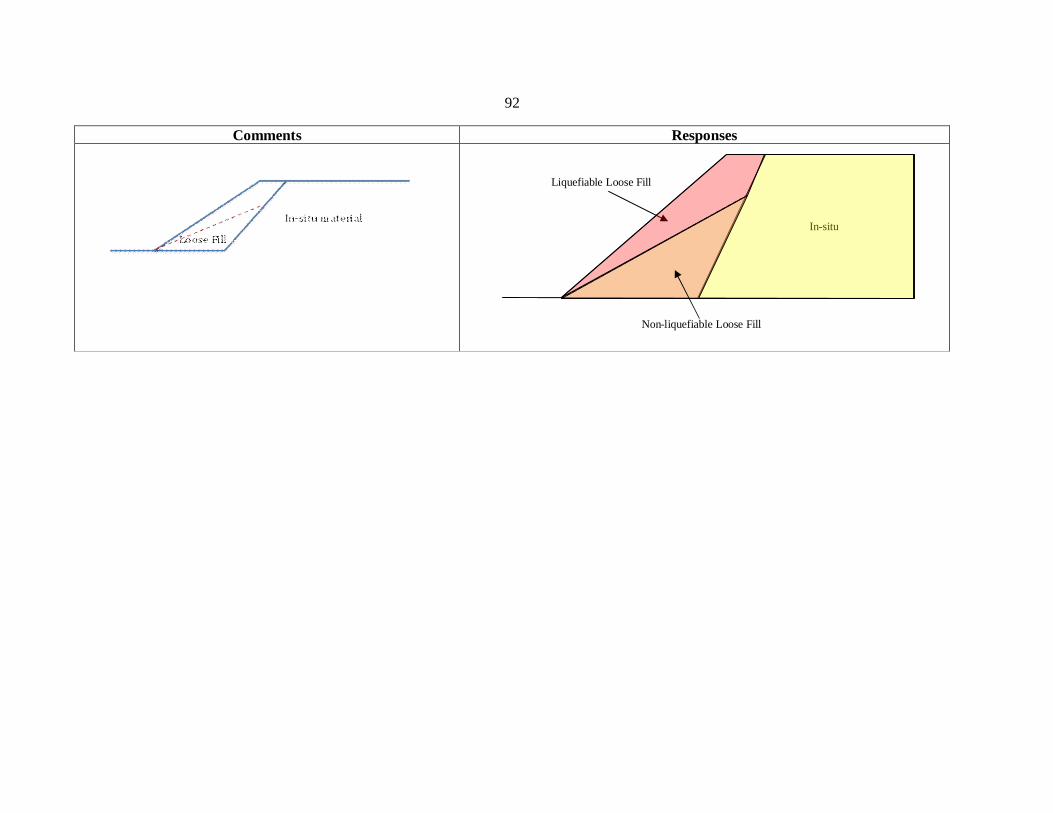
92
Comments Responses
Liquefiable Loose Fill
In-situ
Non-liquefiable Loose Fill
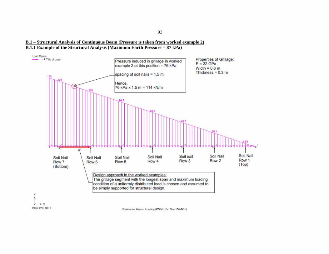
93
B.1 – Structural Analysis of Continuous Beam (Pressure is taken from worked example 2) B.1.1 Example of the Structural Analysis (Maximum Earth Pressure = 87 kPa)
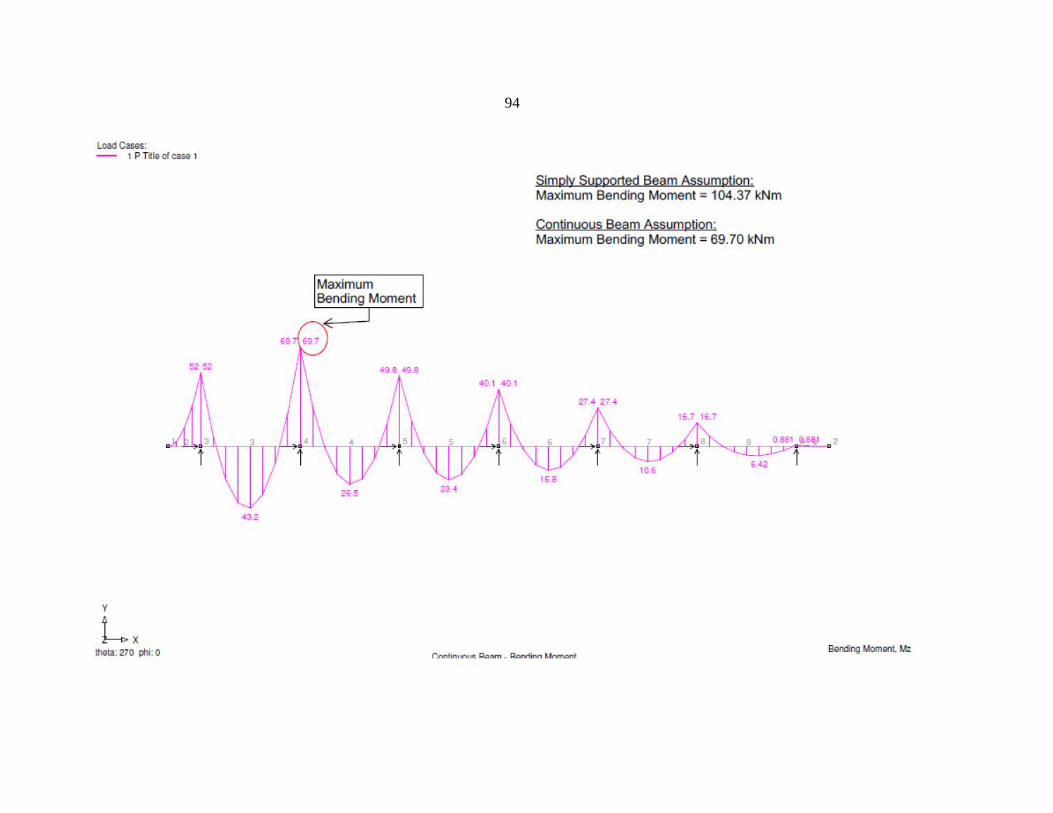
94
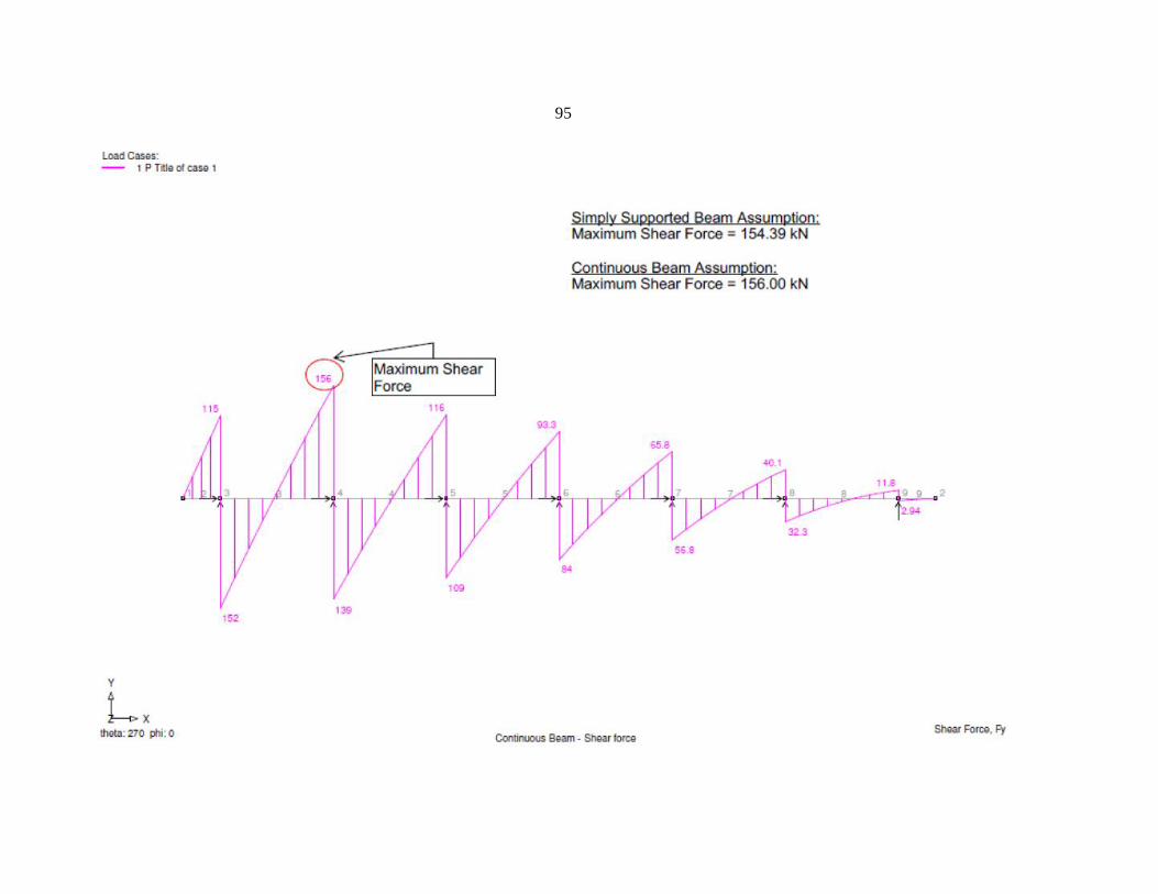
95
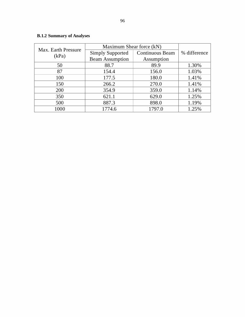
96
B.1.2 Summary of Analyses
Max. Earth Pressure (kPa)
Maximum Shear force (kN) % difference Simply Supported
Beam Assumption Continuous Beam
Assumption 50 88.7 89.9 1.30% 87 154.4 156.0 1.03%
100 177.5 180.0 1.41% 150 266.2 270.0 1.41% 200 354.9 359.0 1.14% 350 621.1 629.0 1.25% 500 887.3 898.0 1.19%
1000 1774.6 1797.0 1.25%
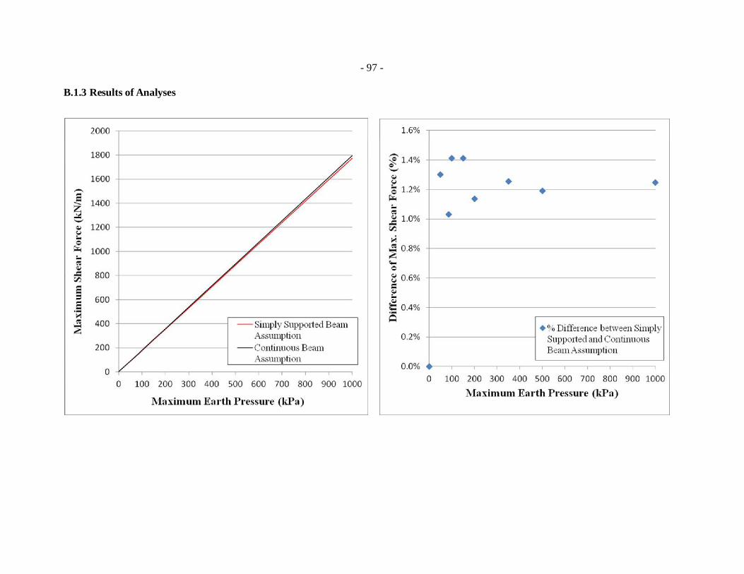
- 97 -
B.1.3 Results of Analyses
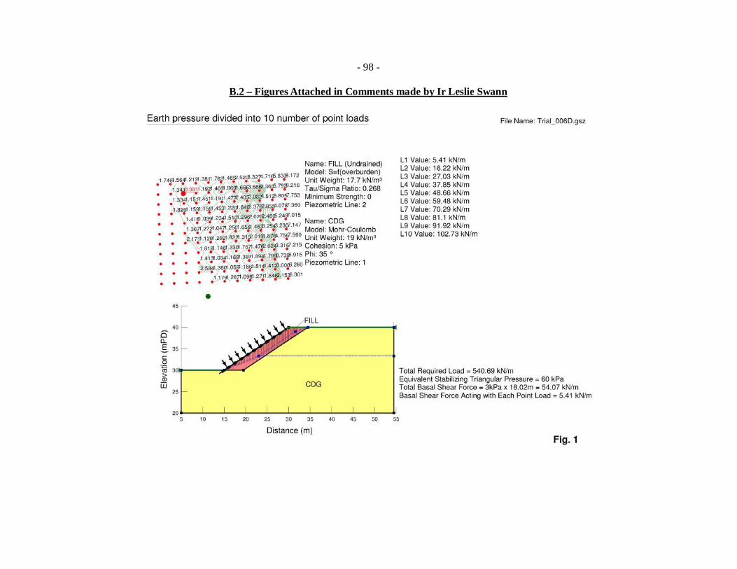
- 98 -
B.2 – Figures Attached in Comments made by Ir Leslie Swann
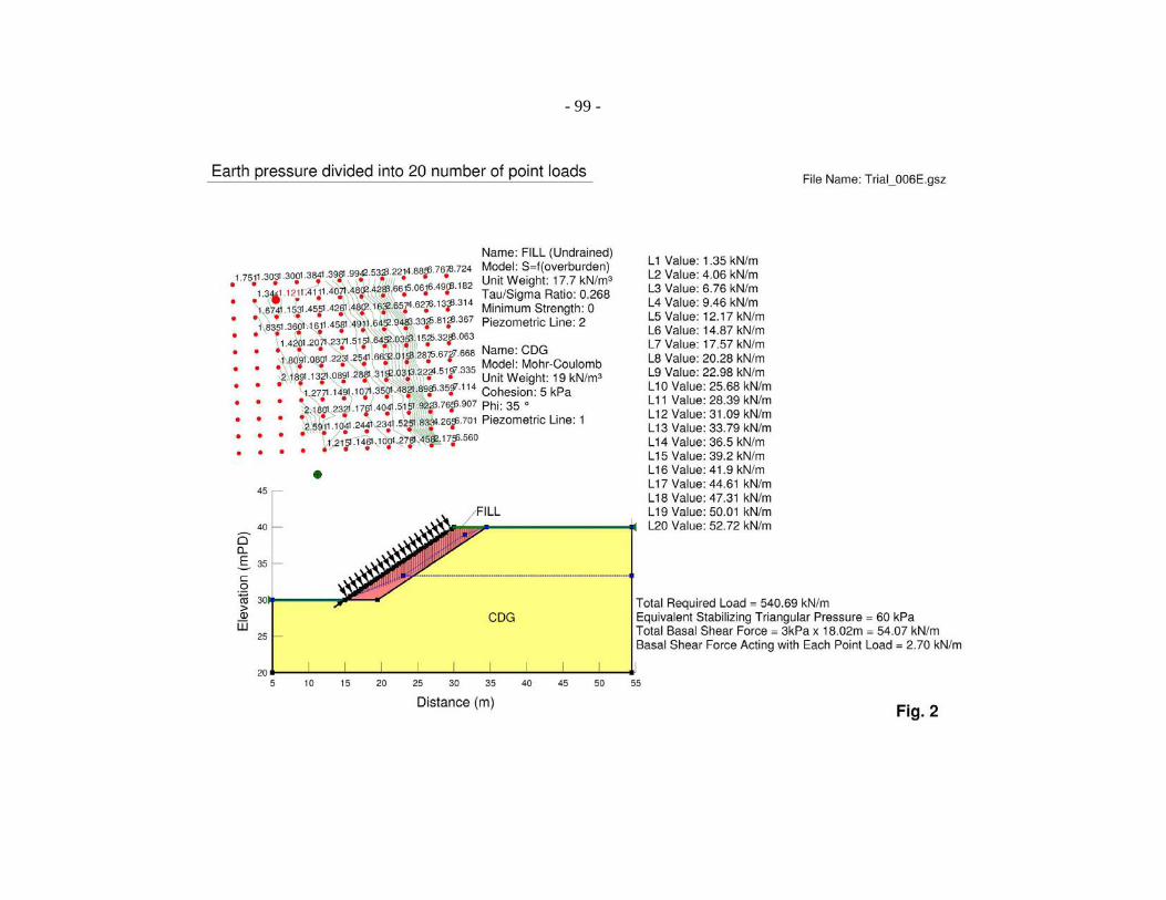
- 99 -
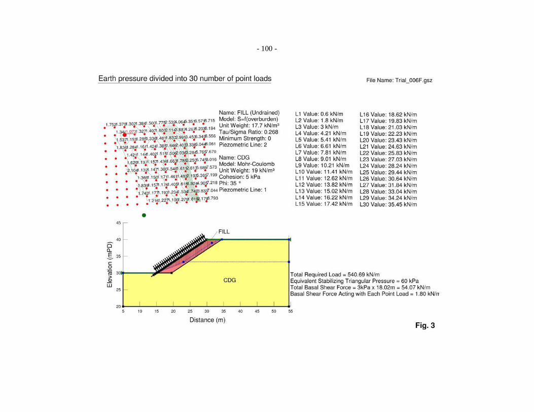
- 100 -

- 101 -
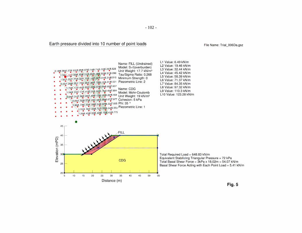
- 102 -
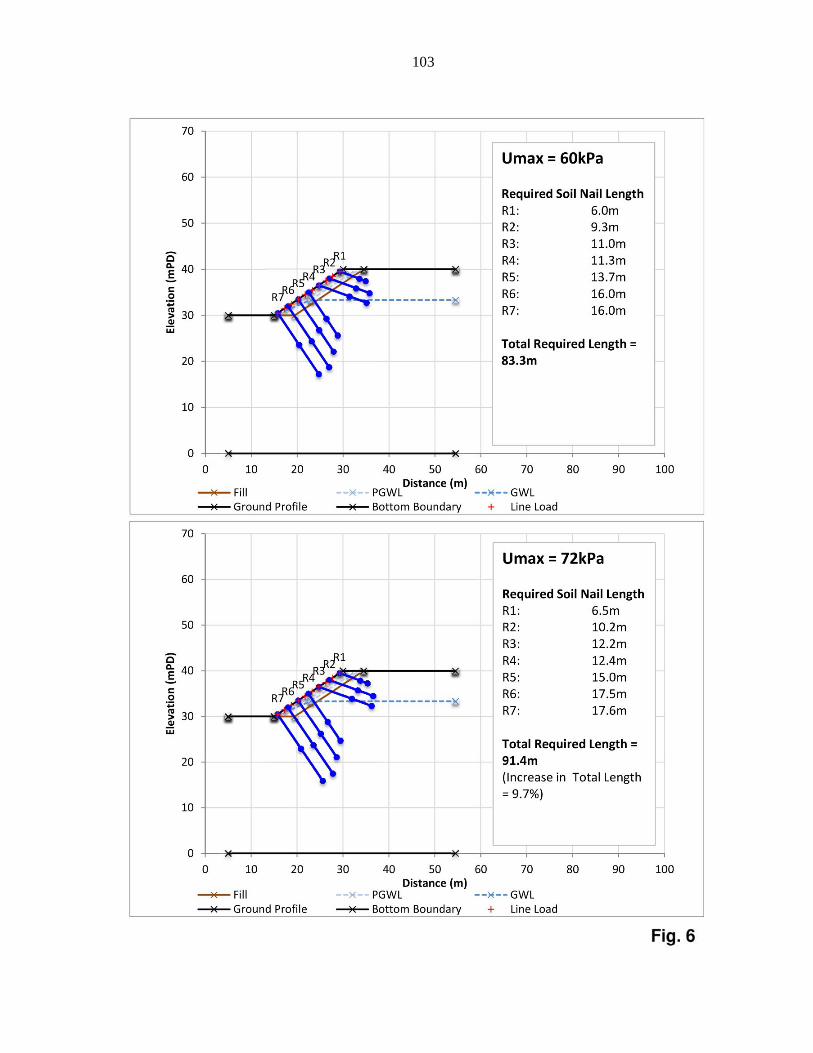
103

104

105
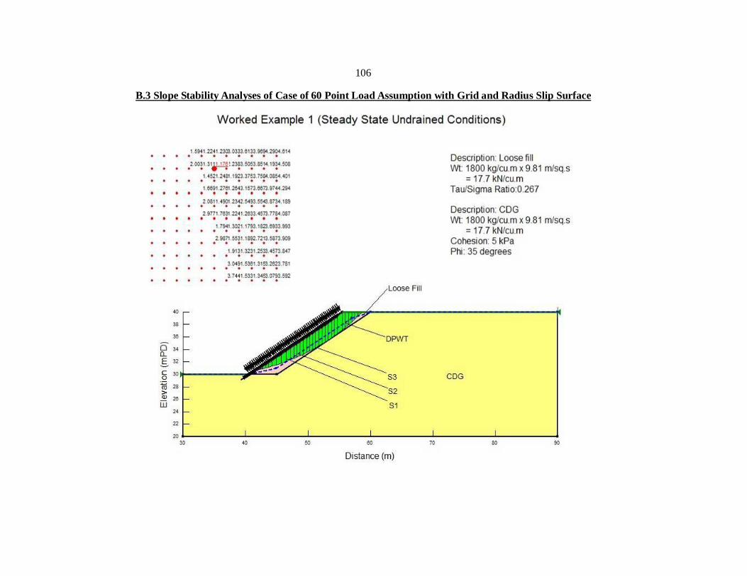
106
B.3 Slope Stability Analyses of Case of 60 Point Load Assumption with Grid and Radius Slip Surface
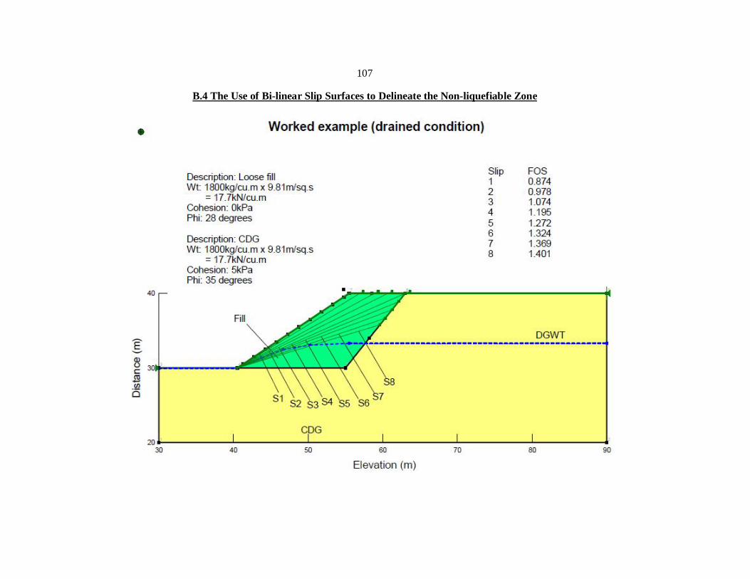
107
B.4 The Use of Bi-linear Slip Surfaces to Delineate the Non-liquefiable Zone