DESIGN GUIDELINES · THE UNIVERSITY OF NORTH CAROLINA AT WILMINGTON DESIGN GUIDELINES ....
279
DESIGN GUIDELINES Architectural & Construction Services Issued May 2019 601 SOUTH COLLEGE ROAD WILMINGTON, NORTH CAROLINA 28403-5910---910-962-7450---FAX 910-962-4014
Transcript of DESIGN GUIDELINES · THE UNIVERSITY OF NORTH CAROLINA AT WILMINGTON DESIGN GUIDELINES ....
THE UNIVERSITY OF NORTH CAROLINA AT WILMINGTON
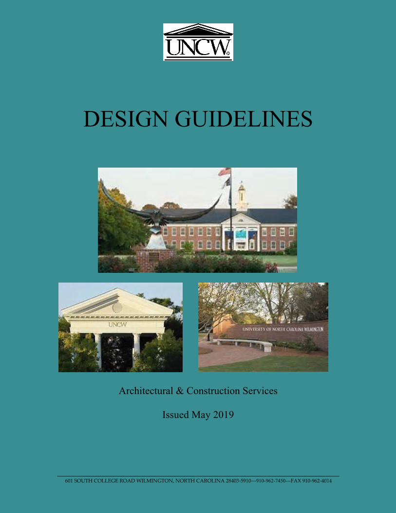
DESIGN GUIDELINES
Architectural & Construction Services
Issued May 2019
601 SOUTH COLLEGE ROAD WILMINGTON, NORTH CAROLINA 28403-5910---910-962-7450---FAX 910-962-4014
THE UNIVERSITY OF NORTH CAROLINA AT WILMINGTON
Introduction
The guidelines have been prepared to guide and assist architectural and engineering consultants, contractors and university personnel with the planning, construction and renovation process as applied to university owned facilities. They provide guidance pertaining to the university’s established preferences and standards in the design and construction process, and standards for design and specification of materials, systems, and components of facilities and procedures that should be followed in performing work for the university.
These guidelines are expected to be followed as a general rule. We realize that each construction and renovation project is unique and may require an occasional deviation from these guidelines. In such cases, the appropriate recommendation or request for deviation from these guidelines should be presented to the university project manager for approval prior to any execution of the deviation.
These guidelines are intended to be a living document that will be updated/modified as changes in technology and practices warrant. To this end, we welcome any comments and recommendations from users pertaining to these guidelines.
Rachel Patrick Director of Architectural and Construction Services

Table of Contents Issue May 2019
This document is a guideline and cannot be used as a final specification
Page 1 of 3
Table of Contents Log of Changes UNCW General Design Guidelines UNCW Original Campus Construction Drawings UNCW Space Allocation Policy 01 00 10 Owner Representatives 01 00 20 Project Summary Checklist 01 00 30 Agency Review 01 00 40 Construction Detail Schedule 01 00 50 Room Numbering 01 00 60 Sustainable Design 01 00 70 Environmental and Safety 01 00 75 Construction Sign 01 00 80 Digging and Excavation 01 00 90 UNCW Supplementary General Conditions 01 10 10 CAD Standards 01 10 15 Specification Standards 04 00 00 Masonry General Requirements 05 50 00 Metal Fabrications 05 73 00 Decorative Metal Railings 06 64 00 Plastic Panels 06 00 00 Wood and Carpentry 07 00 00 Thermal and Moisture General Requirements 07 31 00 Moderate Slope Roofing 07 50 00 Low Slope Roofing 07 53 80 Fall Protection 07 62 00 Sheet Metal Flashing and Trim 07 92 00 Joint Sealants 08 xx xx Technical Guidelines Door Hardware Doors & Frames 08 00 00 Doors – General Guideline 08 11 13 Hollow Metal Doors and Frames 08 14 16 Flush Wood Doors 08 16 16 Acrylic Modified Polyester Doors (FRP) 08 51 13 Aluminum Windows 08 71 00 Door Hardware 09 00 00 Finishes General Requirements 09 29 00 Gypsum Wall Board 09 29 50 Polymer Modified GFRC 09 51 23 Acoustical Panel Ceiling 09 65 00 Resilient Flooring 09 66 23 Resinous Matrix Terrazzo Flooring 09 86 00 Carpeting 09 91 20 Painting 10 11 00 Visual Display Surfaces 10 14 00 Interior and Exterior Signage 10 21 13 Toilet and Shower Compartments 11 00 00 Equipment General Requirements
Table of Contents Issue May 2019
This document is a guideline and cannot be used as a final specification
Page 2 of 3
11 52 26 Projection Screens 12 21 13 Horizontal Louver Blinds 12 24 13 Roller Window Shades (Black-out Shades) 12 93 00 Site Furnishings 14 00 00 Elevator 21 10 00 UNCW Standards for Fire Sprinkler System Design & Installation 22 00 00 General Plumbing 22 05 19 Meters and Gages for Plumbing Equipment 22 05 53 Identification for Plumbing Piping and Equipment 22 11 16 Domestic Water Piping 22 11 23 Domestic Water Pumps 22 13 16 Sanitary Waste and Vent Piping 22 13 19 Sanitary Waste Piping Specialties 22 14 13 Facility Storm Drainage Piping 22 42 00 Commercial Plumbing Fixtures 23 00 00 General Mechanical 23 05 13 Common Motor Requirements for Mechanical Equipment 23 05 16 Expansion Fittings & Loops for HVAC Piping 23 05 19 Meters & Gauges for HVAC 23 05 23 General Duty Valves for HVAC Piping 23 05 53 Identification for HVAC Piping & Equipment 23 05 93 Testing, Adjusting, & Balancing for HVAC 23 07 16 HVAC Equipment Insulation 23 07 19 HVAC Piping Insulation 23 09 00 Instrumentation & Control for HVAC 23 09 93 Sequence of Operation for HVAC Controls 23 11 23 Facility Natural Gas Piping 23 21 13 Hydronic Piping 23 21 23 Hydronic Pumps 23 23 00 Refrigerant Piping 23 25 00 HVAC Water Treatment 23 31 13 Metal Ducts 23 31 19 HVAC Casings 23 36 00 Air Terminals Units 23 37 13 Diffusers, Registers, & Grilles 23 41 33 High Efficiency Particulate Filtration 23 52 16 Condensing Boilers 23 63 13 Air-Cooled Condensers 23 64 16 Centrifugal Water Chillers 23 64 19 Reciprocating Water Chillers 23 65 00 Cooling Towers 23 73 13 Modular Indoor Central- Station Air Handling Units 23 74 33 Dedicated Outdoor- Air Units 23 81 26 Split System Air-Conditioners 23 82 16 Air Coils 23 82 19 Fan Coil Units 23 82 23 Unit Ventilators 23 82 39 Unit Heaters
Table of Contents Issue May 2019
This document is a guideline and cannot be used as a final specification
Page 3 of 3
26 01 00 Electrical General 26 05 33 Conduit 26 08 00 Electrical Testing 26 12 19 Pad Mounted Distribution Transformers 26 18 00 Air Interrupter Switch 26 22 00 Dry Type Transformer 26 24 16 Panelboards 26 27 26 Wiring Devices 26 29 23 Variable Frequency Controllers 26 32 13 Packaged Engine Generators 26 51 00 Interior Luminaries (Included Emergency Lighting) 26 56 00 Site & Exterior Lighting 26 99 99 Section 26 00 00 Appendix 27 00 00 ITSD’s Classroom Recommendations and Technology Baseline 27 05 00 UNCW Telecommunications Standards 28 13 00 UNCW Standards for Installation of Access Control Equipment 28 16 00 UNCW Guidelines for the Installation of Intrusion/Burglary Systems 28 23 00 UNCW Standards for Installation of Cameras and Camera Systems 28 31 13 Fire & Security Alarm Systems 31 31 16 Termite Control 32 00 00 Exterior Improvements 32 12 16 Asphalt Paving 32 90 00 UNCW Landscaping Standards
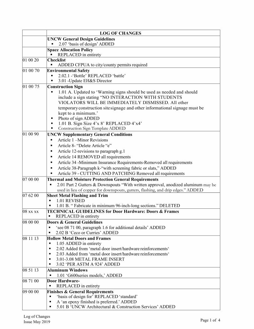
LOG OF CHANGES UNCW General Design Guidelines 2.07 ‘basis of design’ ADDED
Space Allocation Policy REPLACED in entirety
01 00 20 Checklist ADDED CFPUA to city/county permits required
01 00 70 Environmental Safety 2.02.1 -‘Bottle’ REPLACED ‘battle’ 3.01 -Update EH&S Director
01 00 75 Construction Sign 1.01 A. Updated to ‘Warning signs should be used as needed and should
include a sign stating “NO INTERACTION WITH STUDENTSVIOLATORS WILL BE IMMEDIATELY DISMISSED. All othertemporary construction site signage and other informational signage must bekept to a minimum.’
Photo of sign ADDED 1.01 B. Sign Size 4’x 8’ REPLACED 4’x4’ Construction Sign Template ADDED
01 00 90 UNCW Supplementary General Conditions Article 1 –Minor Revisions Article 8- “Delete Article “e” Article 12-revisions to paragraph g.1 Article 14 REMOVED all requirements Article 34 -Minimum Insurance Requirements-Removed all requirements Article 38-Paragraph k-“with screening fabric or slats,” ADDED Article 39 - CUTTING AND PATCHING Removed all requirements
07 00 00 Thermal and Moisture Protection General Requirements 2.01 Part 2 Gutters & Downspouts “With written approval, anodized aluminum may be
used in lieu of copper for downspouts, gutters, flashing, and drip edges.” ADDED07 62 00 Sheet Metal Flashing and Trim
1.01 REVISED 1.01 B. “ Fabricate in minimum 96-inch-long sections.” DELETED
08 xx xx TECHNICAL GUIDELINES for Door Hardware: Doors & Frames REPLACED in entirety
08 00 00 Doors & General Guidelines ‘see 08 71 00, paragraph 1.6 for additional details’ ADDED 2.02 B ‘Ceco or Curries’ ADDED
08 11 13 Hollow Metal Doors and Frames 1.05 ADDED in entirety 2.02 Added from ‘metal door insert/hardware reinforcements‘ 2.03 Added from ‘metal door insert/hardware reinforcements‘ 3.01-3.08 METAL FRAME INSERT 3.02 ‘PER ASTM A 924’ ADDED
08 51 13 Aluminum Windows 1.01 ‘G600series models,’ ADDED
08 71 00 Door Hardware- REPLACED in entirety
09 00 00 Finishes & General Requirements ‘basis of design for’ REPLACED ‘standard’ A ‘an epoxy finished is preferred.’ ADDED 5.01 B ‘UNCW Architectural & Construction Services’ ADDED
Log of Changes Issue May 2019 Page 1 of 4

Log of Changes Issue May 2019 Page 2 of 4
09 91 20 Painting A ‘basis of design’ REPLACED ‘standard’ A ‘For interior paint, select from UNCW approved color palette’ ADDED 2.04 A ‘manufacturer's’ ADDED/’as manufactured by Duron Paint Mfg. Co.
DELETED10 14 00 Interior & Exterior Signage
‘01 00 50 Room Numbering’ REPLACED ‘01 0060’ 1.02 A ’01 00 50 Room Numbering’ REPLACED ‘00710’
10 21 13 Toilet & Shower Compartments 1.06 D ‘hex’ REPLACED ‘sex’ 1.06 Accessories, ADDED ‘E. The University provides owner standard toilet paper
dispensers, soap dispensers, paper towel dispensers, and sanitary napkin holders. Thecontractor installs the owner provided accessories.’
11 00 00 Equipment General Requirements 9.01 ‘bids’ REPLACED ‘bins’ 9.01 A. UPDATED IN ENTIRETY 4.01 ‘network’ ADDED
12 93 00 Site Furnishings A ‘Planks: IPE Wood’ ADDED/ 1.01 A/B DELETED 1.02 Bike Rack Photo ADDED 1.09 Bus Shelters ADDED 1.08 Parking Lot Removable Bollards – Detail of bollard replaced with updated detail
14 00 00 Elevator ADDED in entirety
21 10 00 UNCW Standards for Fire Sprinkler System & Fire Suppression Design&Installation REPLACED in entirety
22 05 13 Common Motor Requirements for Plumbing
22 11 16 Domestic Water Piping 1.01 Materials & Accessories “With written approval PEX-a may be used in lieu of
copper for domestic water pipe less than or equal to 2.” ADDED22 13 16 Sanitary Waste and Vent Piping
1.01 Materials “B. With written approval PVC may be used in lieu of cast-iron pipefor drain, waste or vent under slab piping.” ADDED
23 00 00 Mechanical 1.02 D "SW" -ADDED 1.02 I "or approved equal."-ADDED
23 05 19 Meters & Gages for HVAC Piping 1.01 B TU Meters: Onicon System-10 BTU meter, LonWorks communication, F-
3500 Electromagnetic Flow Meter-ADDED23 07 19 Hydronic Piping
1.01 A ‘preformed’ REPLACED ‘ performed’
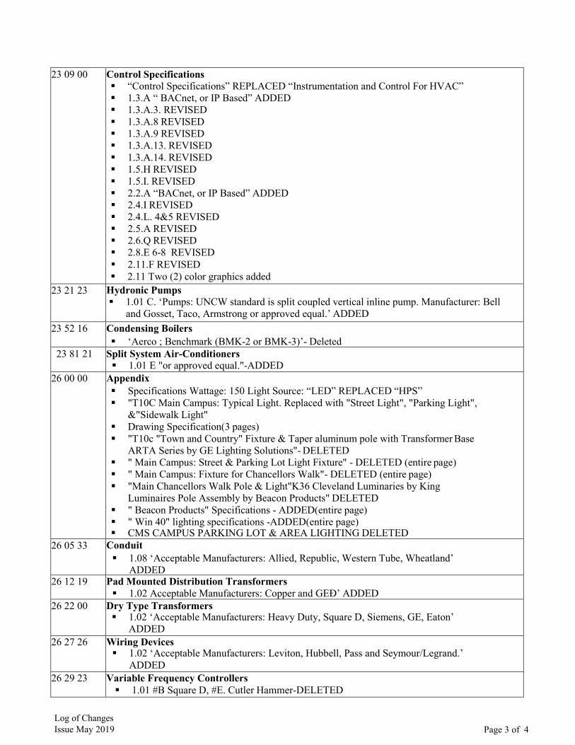
23 09 00 Control Specifications “Control Specifications” REPLACED “Instrumentation and Control For HVAC” 1.3.A “ BACnet, or IP Based” ADDED 1.3.A.3. REVISED 1.3.A.8 REVISED 1.3.A.9 REVISED 1.3.A.13. REVISED 1.3.A.14. REVISED 1.5.H REVISED 1.5.I. REVISED 2.2.A “BACnet, or IP Based” ADDED 2.4.I REVISED 2.4.L. 4&5 REVISED 2.5.A REVISED 2.6.Q REVISED 2.8.E 6-8 REVISED 2.11.F REVISED 2.11 Two (2) color graphics added
23 21 23 Hydronic Pumps 1.01 C. ‘Pumps: UNCW standard is split coupled vertical inline pump. Manufacturer: Bell
and Gosset, Taco, Armstrong or approved equal.’ ADDED23 52 16 Condensing Boilers
‘Aerco ; Benchmark (BMK-2 or BMK-3)’- Deleted23 81 21 Split System Air-Conditioners
1.01 E "or approved equal."-ADDED26 00 00 Appendix
Specifications Wattage: 150 Light Source: “LED” REPLACED “HPS” "T10C Main Campus: Typical Light. Replaced with "Street Light", "Parking Light",
&"Sidewalk Light" Drawing Specification(3 pages) "T10c "Town and Country" Fixture & Taper aluminum pole with Transformer Base
ARTA Series by GE Lighting Solutions"- DELETED " Main Campus: Street & Parking Lot Light Fixture" - DELETED (entire page) " Main Campus: Fixture for Chancellors Walk"- DELETED (entire page) "Main Chancellors Walk Pole & Light"K36 Cleveland Luminaries by King
Luminaires Pole Assembly by Beacon Products" DELETED " Beacon Products" Specifications - ADDED(entire page) " Win 40" lighting specifications -ADDED(entire page) CMS CAMPUS PARKING LOT & AREA LIGHTING DELETED
26 05 33 Conduit 1.08 ‘Acceptable Manufacturers: Allied, Republic, Western Tube, Wheatland’
ADDED26 12 19 Pad Mounted Distribution Transformers
1.02 Acceptable Manufacturers: Copper and GEÐ’ ADDED26 22 00 Dry Type Transformers
1.02 ‘Acceptable Manufacturers: Heavy Duty, Square D, Siemens, GE, Eaton’ADDED
26 27 26 Wiring Devices 1.02 ‘Acceptable Manufacturers: Leviton, Hubbell, Pass and Seymour/Legrand.’
ADDED26 29 23 Variable Frequency Controllers
1.01 #B Square D, #E. Cutler Hammer-DELETED
Log of Changes Issue May 2019 Page 3 of 4
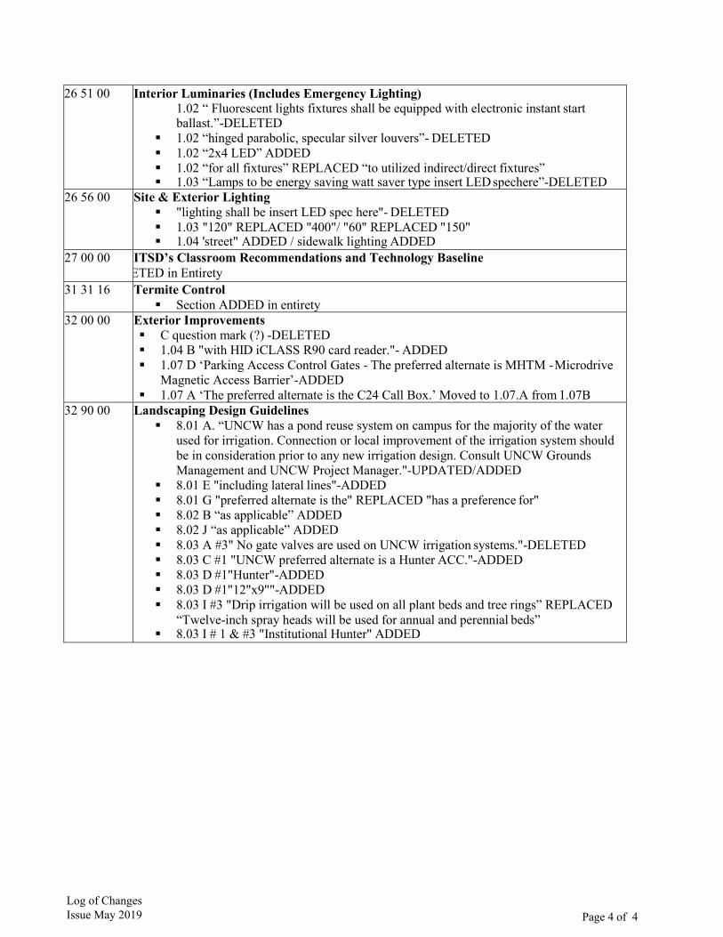
26 51 00 Interior Luminaries (Includes Emergency Lighting) 1.02 “ Fluorescent lights fixtures shall be equipped with electronic instant start ballast.”-DELETED
1.02 “hinged parabolic, specular silver louvers”- DELETED 1.02 “2x4 LED” ADDED 1.02 “for all fixtures” REPLACED “to utilized indirect/direct fixtures” 1.03 “Lamps to be energy saving watt saver type insert LED spechere”-DELETED
26 56 00 Site & Exterior Lighting "lighting shall be insert LED spec here"- DELETED 1.03 "120" REPLACED "400"/ "60" REPLACED "150" 1.04 'street" ADDED / sidewalk lighting ADDED
27 00 00 ITSD’s Classroom Recommendations and Technology Baseline ETED in Entirety
31 31 16 Termite Control Section ADDED in entirety
32 00 00 Exterior Improvements C question mark (?) -DELETED 1.04 B "with HID iCLASS R90 card reader."- ADDED 1.07 D ‘Parking Access Control Gates - The preferred alternate is MHTM - Microdrive
Magnetic Access Barrier’-ADDED 1.07 A ‘The preferred alternate is the C24 Call Box.’ Moved to 1.07.A from 1.07B
32 90 00 Landscaping Design Guidelines 8.01 A. “UNCW has a pond reuse system on campus for the majority of the water
used for irrigation. Connection or local improvement of the irrigation system shouldbe in consideration prior to any new irrigation design. Consult UNCW GroundsManagement and UNCW Project Manager."-UPDATED/ADDED
8.01 E "including lateral lines"-ADDED 8.01 G "preferred alternate is the" REPLACED "has a preference for" 8.02 B “as applicable” ADDED 8.02 J “as applicable” ADDED 8.03 A #3" No gate valves are used on UNCW irrigation systems."-DELETED 8.03 C #1 "UNCW preferred alternate is a Hunter ACC."-ADDED 8.03 D #1"Hunter"-ADDED 8.03 D #1"12"x9""-ADDED 8.03 I #3 "Drip irrigation will be used on all plant beds and tree rings” REPLACED
“Twelve-inch spray heads will be used for annual and perennial beds” 8.03 I # 1 & #3 "Institutional Hunter" ADDED
Log of Changes Issue May 2019 Page 4 of 4

UNCW General Design Guidelines Issue May 2019
This document is a guideline and cannot be used as a final
specification
Page 1 of 12
UNCW General Design Guidelines
Part 1: General
1.01 All UNCW Buildings are owned by the State of North Carolina and are entrusted to UNCW.
1.02 These standards apply to all UNCW buildings irrespective of the funding source.
1.03 Exceptions to this guideline can be made only with the written approval of the UNCW Architectural and Construction Services.
1.04 New buildings at UNCW should meet the SCO standards for 75-year construction.
Part 2: General Exterior - Architectural
2.01 The UNCW Board of Trustees has mandated that the design of the Main Campus is to be Georgian-Style. There are to be no exceptions to this policy.
2.02 In order to carry out this mandate of the UNCW Board of Trustees, the architect should reference the original UNCW campus construction drawings which include the following buildings: Alderman Hall, James Hall, Hoggard Hall, Kenan Hall, and Kenan Auditorium for design and especially for the exterior details of the buildings. The architect should bear in mind that the original campus was designed by the master of the classical-style building, Leslie Boney, and should be the source of ongoing design at UNCW. A. Reference Material:
1. The original UNCW campus construction documents, which are included as anattachment to this section. See UNCW Original Campus Construction Documents.
2. “The Four Books of Architecture” by Andrea Palladio.
2.03 Columns & Pilasters: A. Exterior columns at major entrance porticos with no exceptions are to be Temple of
the Winds – fluted.B. Exterior pilasters at major entrance porticos with no exceptions are to be Temple of the
Winds – rectangular - fluted.C. Exterior columns on minor porches are to be Doric style – fluted.D. Exterior pilasters on minor porches are to be Doric style – rectangular –fluted.
2.04 Roofs: A. Buildings are to have a hip roof – not gabled roofs.
1. See sections 07 31 00 Moderate Slope Roofing and 07 50 00 Low Slope Roofing.

UNCW General Design Guidelines Issue May 2019
This document is a guideline and cannot be used as a final
specification
Page 2 of 12
B. Roof slopes are to be the same ratio as Alderman Hall, 6:12. (See original drawingsht.25.)C. Flat roofs are not allowed on UNCW Main Campus except in a limited way on secondary
entrances porches or as designated by the UNCW Architectural and Construction Services in certain renovation project or additions to existing UNCW buildings.
D. Pediments at entrances or on major columned porches are to have the same slope, detail, and design as Alderman Hall.
E. Roof terraces, gardens, living roofs, etc. are not allowed.F. Balconies and elevated terraces or patios are not allowed.G. Dormer windows or ventilators are not allowed.H. Skylights are not allowed.I. Gutters and Downspouts:
1. No hidden gutters allowed.2. Downspouts are to connect into the stormwater drainage system and are not to
be discharged onto the ground unless there is a strict requirement to do so fromSCO.
3. Color: Match the color of downspouts at Hoggard Hall.4. See sections 05 50 00 Metal Fabrications and 07 62 00 Sheet Metal Flashing & Trim.
2.05 Windows: A. Windows should follow the UNCW Georgian – divided light style.B. Large plate glass windows with aluminum, storefront frames are not allowed
unless specifically authorized by the UNCW Architectural and ConstructionServices.
C. Windows shall be fixed. Operable windows are not allowed.1. See section 08 51 13 Aluminum Windows
D. Window sills are to precast concrete and are to be the same design as the window sills forAlderman Hall.
E. The window sill height is to be 3’-4” from the floor.
2.06 Exterior Materials: A. No wood is allowed on the exterior of any building, ancillary building, or mechanical and
electrical enclosures. This includes doors, gates, louvers, window trim, door frames, and trim, etc.
B. All exterior trim to include cornices, columns, pilasters, door frames for main entrance doors with no exceptions are to be GFRC (Glass Fiber Reinforced Concrete) with a painted finish.(See section 09 29 50 Polymer Modified GFRC).
C. Exterior doors are to be FRP or Aluminum with continuous hinges. See section 08 16 16.1. Exterior utility doors may be hollow metal if out of public view. See section 08 11 13.

UNCW General Design Guidelines Issue May 2019
This document is a guideline and cannot be used as a final
specification
Page 3 of 12
2.07 Brickwork: A. The basis of design brick for new buildings is to be Statesville Brick Company – Red Royal
Special. It is to be a modular brick. The bond for the brick is a running bond with a rakedjoint. The mortar color is light grey. See section 04 00 00 Masonry.
B. Additions to existing buildings should match the brick, mortar color, etc. of theexisting building.
C. Quoins are to be the same design as Alderman Hall.D. Jack arches are to be the same design as Alderman Hall.E. Brick veneer expansion joint sealant to match the brick color. (See 07 92 00 Joint Sealants)
2.08 Building Construction: A. Buildings are to have a steel structure unless the design loads prove otherwise.B. Wood framed buildings are not allowed without the written approval of the UNCW
Architectural and Construction Services.C. Exterior walls are to be a metal stud with a brick veneer.
1. Provide Moisture and Mold Resistant gypsum board on the interior side.D. Buildings are to be slab on grade with the First-Floor elevation to be 2’-6” above the final site
elevations.E. A crawl space is not allowed.F. The floor-to-floor height of a building is to be 16’-0” for general classroom-office building
but can be increased with the approval of the UNCW Architectural and Construction Servicesfor wet laboratory buildings to meet ventilation requirements.
2.09 Exterior Mechanical and Electrical Accessories and Equipment: A. Laboratory exhaust should be disguised in buildings as chimneys.
2.10 Other Exterior Items: A. Exterior handrails are to be the same design as the Alderman Hall exterior handrail.B. Exterior risers and runs are to be precast with the same design as Alderman Hall main
entrance steps.C. Entrance porches are to have slate flooring.D. See UNCW Original Campus Construction Documents.
Part 3: Exterior Building Signage – UNCW Main Campus
3.01 The name of the building is to be mounted in the cornice on all sides of the building or as determined by the UNCW Architectural and Construction Services.
UNCW General Design Guidelines Issue May 2019
This document is a guideline and cannot be used as a final
specification
Page 4 of 12
3.02 UNCW has a standard for building lettering. (See Section 10 14 00 Signage). This standard must be followed with no exceptions. The letters should be specified by the architect so that there is a stand-off for mounting the letters away from the cornice. A. The color of the letters on a white background is bronze.B. If letters must be mounted on brick, the color is to be white.
3.03 The name of the building will be provided to the consultant by the UNCW Architectural and Construction Services.
Part 4: Exterior - UNCW CMS Campus
4.01 New buildings or additions to the existing buildings are to follow the form of the original CMS building.
4.02 The buildings are to have flat roofs. (Less than 3:12pitch)
4.03 The brick and mortar are to match the brick and mortar of the original CMS building.
4.04 Exterior trim is to match the original CMS building.
Part 5: Interior – Main Campus and CMS
5.01 Generally, all interior walls are to be painted.
5.02 The ceiling grid is to be 2’x2’. The grid rail is to be 15/16 inch in width. The color of the ceiling tile is white.
5.03 All exterior windows are to have Venetian blinds. The color of the blind is white.
5.04 Rooms that require black-out shades are to also have Venetian blinds on the exterior side of the blind/shade assembly.
5.05 Built-in casework is to be very limited in the building, durable and shall be vetted during the design process.
5.06 Lighting: A. Generally, the designer should rely on a standard 2 x 4 parabolic fixtures
unless otherwise noted. The fixture should have two light levels.1. Classrooms and Seminar rooms shall have Direct-Indirect type fixtures.2. Direct-Indirect type fixtures as an Add Alternate:
UNCW General Design Guidelines Issue May 2019
This document is a guideline and cannot be used as a final
specification
Page 5 of 12
a. Designers shall specify the use of Direct-Indirect type fixtures in place of parabolicfixtures in all occupiable spaces in building as an Add Alternate cost. Corridorsincluded. Verify included spaces during Design Development review.
B. Pendant lighting is allowed as approved. Not generally recommended.C. Track lighting, recessed can lighting, etc., is limited to the building lobby.
5.07 Buildings should have separate rooms for recycling (each floor), general receiving, mail delivery to the building, and vending. All these rooms should have lockable doors.
5.08 HAZMAT rooms and external storage requirements should be determined on a building by building basis with UNCW EH&S.
5.09 Vending rooms, mail rooms, storage rooms, etc. should be designed so that they can be converted into programmed for other functions to provide increased flexibility for future space requirements.
Part 6: Interior – Walls
6.01 Walls at the exterior perimeter of the building and walls around wet areas such as restrooms are to have mold and moisture resistant fiberglass gypsum board. (See section 09 29 00 Gypsum Wall Board)
6.02 Interior walls at the following locations should go to structure: restrooms, fire stairs, vending rooms, classrooms, lobbies, corridors, conference rooms, seminar rooms, distance learning classrooms, laboratories, lecture halls, and janitorial, telecom, security, and audio-visual closets.
6.03 Generally, the exception is the wall between faculty and staff offices, and office support spaces such as file rooms, storage rooms, mail rooms, recycling rooms, etc. Those walls should extend 12” above the ceiling unless there is a requirement for sound security or rating requirement then the walls should be extended to structure.
6.04 Block walls are not required around core restrooms.
6.05 Dividing walls between classrooms, seminar rooms, distance learning classrooms, and lecture halls should have sound attenuating gypsum board.
6.06 All walls should have sound insulation that is continuous from floor to top of wall.

UNCW General Design Guidelines Issue May 2019
This document is a guideline and cannot be used as a final
specification
Page 6 of 12
Part 7: Interior – Main Campus
7.01 Building Lobbies A. The building lobby should have a higher standard of finish the rest of the building.B. Multiple level lobbies and atriums are not allowed without the permission of the UNCW
Architectural and Construction Services.C. The building lobby should be designed as a Georgian style room with classical trim
to include the cornice, pilasters, moldings, wainscoting, and baseboards.D. A hard-finished ceiling is allowed in the lobby design as long as a system can be devised to
provide a clear, accessible routing path for utilities above the ceiling such as telecom wiring, security wiring, etc.
E. Pendant lighting is not allowed.F. Specialty lighting, such as recessed can lighting, is allowed.G. The flooring should be epoxy terrazzo with a classical design to imitate marble or granite
flooring. (See section 09 66 23 Resinous Matrix Terrazzo Flooring.)H. Elevators, restrooms, service closets, etc. should not open directly into the main building
lobby but should be in a separate but immediately accessible area.I. See the UNCW Teaching Laboratory (Psychology Building) for an example of an approved
lobby design.
7.02 Corridors: A. Floor: Vinyl Tile.B. Walls: Painted.C. Ceiling: 2 x 2 lay-in acoustical tileD. Base: Vinyl.E. Door frames: Painted steel.F. Doors: Solid core with wood (maple) laminate veneer with a clear finish.
1. Provide view windows at passage doors within corridors and doors into stairs.G. Lighting: 2 x 4 lay-in fixture
7.03 Staff and Faculty Offices A. Floor: Carpet.B. Walls: Painted.C. Ceiling: 2 x 2 lay-in acoustical tileD. Base: Vinyl.

UNCW General Design Guidelines Issue May 2019
This document is a guideline and cannot be used as a final
specification
Page 7 of 12
E. Door frames: Painted steel.F. Doors: Solid core with wood (maple) laminate veneer with a clear finish. No view window.G. Lighting: 2 x 4 lay-in fixture.
7.04 Office Support Spaces – Storage, Mail, File, Photocopy, Kitchens, etc. A. Floor: Vinyl Tile.B. Walls: Painted.C. Ceiling: 2 x 2 lay-in acoustical tileD. Base: Vinyl.E. Door frames: Painted steel.F. Doors: Solid core with wood (maple) laminate veneer with a clear finish. No view window.G. Lighting: 2 x 4 lay-in fixture – dual level lighting.
Part 8: General Classrooms and Seminar Rooms
A. Floor: Vinyl Tile.B. Walls: Painted.C. Ceiling: 2 x 2 lay-in.D. Base: Vinyl.E. Door frames: Painted steel.F. Doors: Solid core with wood (maple) laminate veneer with a clear finish. No view window.G. Lighting: 2 x 4 lay-in fixture – dual level lighting.H. Unless there is a fixed projection screen, classrooms are to have a motorized, retractable
screen located above the ceiling. (See Section 11 52 26 Projection Screens)1. See section 27 00 00 ITSD Classroom Recommendations and Technology Baseline.
I. Classrooms are to have whiteboards and tack boards. (See 10 11 00 Visual Display Surfaces)1. See section 27 00 00 ITSD Classroom Recommendations and Technology Baseline.
8.02 Tiered Classrooms, Conference Rooms, Distance Learning Classrooms, Lecture Halls, and
Multipurpose Rooms:
A. Floor: Carpet.B. Walls: Painted.C. Ceiling: 2 x 2 lay-in acoustical tileD. Base: Vinyl.E. Door frames: Painted steel.

UNCW General Design Guidelines Issue May 2019
This document is a guideline and cannot be used as a final
specification
Page 8 of 12
F. Doors: Solid core with wood (maple) laminate veneer with a clear finish. No view window.G. Lighting. 2 x 4 lay-in fixture.H. Widows are to have manual blackout shade on the interior (between jambs) with
Venetian blinds on the outside of the window (wall mounted).1. See section 12 24 13 Roller Window Shades for block-out shades.2. See section 12 21 13 Horizontal Louver blinds for Venetian blinds.
I. Floor outlets for electrical and communications are allowed in conference rooms with theaffixed table.
J. Multipurpose rooms are to have adjacent furniture storage closets preferablywith doors opening into the room and not the corridor.
K. Unless there is a fixed projection screen, classrooms are to have a motorized, retractablescreen located above the ceiling. (See section 11 52 26 Projection Screens)1. See section 27 00 00 ITSD Classroom Recommendations and Technology Baseline.
L. Classrooms are to have whiteboards and tack boards. (See 10 11 00 Visual Display Surfaces)1. See section 27 00 00 ITSD Classroom Recommendations and Technology Baseline.
M. Private conference rooms (a conference room that is only accessible througha lockable, private office) are not allowed.
8.03 Mechanical Rooms: A. Mechanical rooms on the ground floor are to have painted walls and a sealed floor.B. Mechanical rooms on upper floors of the building are to have a continuous curb
running around the perimeter of the space with a continuous, waterproof membrane.C. Floor drains are required in all mechanical rooms.
8.04 Rest Rooms, Showers Rooms, Locker Rooms A. Restrooms are to be grouped into a central core near the main entrance to the building
with the elevators, janitorial closets, electrical closets, etc.B. Separate faculty or private restrooms are typically not allowed. If it is required by
LEED, then a shower-dressing room component can be added to each of the corerestrooms.
C. Rest Rooms are to have ceramic tile floors and ceramic mosaic tile behind wet areas.1. The remaining walls in restrooms are to be painted with latex.
8.05 Custodial Closets A. The following requirements apply to the design of custodial closets. In general, one custodial
closet shall be provided for each 20, 000 gross square feet of building floor space, but not lessthan one per floor. The minimum size shall be eighty square feet. No dimension of the roomshall be less than six feet. These rooms shall not be used for passageways, pipe or ductchases, electrical panels telephone equipment, mechanical equipment or elevator controls.Each custodial room shall contain the following:
UNCW General Design Guidelines Issue May 2019
This document is a guideline and cannot be used as a final
specification
Page 9 of 12
1. A recessed mop receptor with curb vice a service sink. The mop receptor shall be located in one corner space beside the entrance. It is to be ceramic tile; the remainder of the floor may be trowel finished concrete or V.A.T. A waterproof membrane must be provided underneath the entire floor. The entire floor must slope toward the mop receptor.
2. Hot and cold outlets/faucets, not less than 24 inches above the floor receptor and provided with hose bibs, siphon breaker devices and bucket hooks on the hose bibs.
3. Pegs for rotary brush storage, hangars and wall space for dust mops and brooms, and hangars for wet mops above the floor receptors. Wet mop hangars shall allow the mops to hang with the mop portion down.
4. A minimum of 24 square feet of shelving, the minimum depth of 24 inches to be used for the storage of maintenance supplies and equipment. Shelving shall be adequately secured to the wall. Wood shelves are prohibited.
5. Positive ventilation provided by an exhaust fan to accommodate charging of cleaning equipment batteries, drying of mops, etc.
6. Recessed or guard protected light fixtures.7. A minimum of one 120-volt grounded AC electric duplex receptacle located on open wall
space, near the light switch.8. A door at least 36 inches in width, preferably opening outward.9. Floor space for large floor machines.10. Hard wall surfaces.11.A storage slot for a ladder, preferably at the end of the shelving.
B. Custodial closets should be centrally located and not at the end of dead-end corridors, ona stair landing nor inside another room, under stairways or in a narrow space.
C. Custodial closets should be located as close as possible to the receiving entrance and elevator.The design must accommodate their use as washrooms, storage rooms, lockers and lunchrooms for custodians.
8.06 Storage Rooms: A. Every building of 40,000 gross square feet or larger shall have a storage room of at least 200
square feet for custodial supplies and equipment. It should be located near the elevator.1. Shelves having a minimum depth of 12 inches shall be provided on at least one wall.2. The entry door shall be at least 36 inches in width.
8.07 Stairs - General A. Provide handrails on both sides of stairs.
8.08 Stairs – Enclosed Fire Stairs A. Walls, if gypsum board, provide the impact-rated type. (See section 09 29 00 Gypsum Board)B. Doors shall be provided with vision panels.
UNCW General Design Guidelines Issue May 2019
This document is a guideline and cannot be used as a final
specification
Page 10 of 12
8.09 Kitchens A. Walls: FRP panelsB. Floor & Base: (Reserved)C. Base: (Reserved)D. Ceiling: 2x2 Lay-in FRP faced tiles. Coordinate with Health Dept. requirements.
8.10 Section references for items noted in Part 8. A. All sections should be reviewed for additional design guidance.B. The following sections provide additional information mentioned in Part
8.1. 06 00 00 Wood and Carpentry2. 08 00 00 Doors – General Guidelines3. 08 11 13 Hollow Metal Doors and Frames4. 08 14 16 Flush Wood Doors.5. 08 16 16 FRP Doors6. 09 00 00 Finishes7. 09 29 00 Gypsum Wall Board
Part 9: Energy Conservation
9.01 Energy conservation must be an essential part of design and development for all new construction and renovation projects. In addition to basic conservation requirements established by the State of North Carolina, design development should consider the utilization of passive solar techniques as part of the design development process. The consideration of non-conventional and renewable energy sources should be considered. A. See section 01 00 70 Sustainability
Part 10: Utilities Dig Permit
10.01 The specific University procedures for obtaining a Dig Permit (See 01 00 80) shall be followed prior to any penetration of the ground. In addition, the Utility Locator Service shall be contacted. There exists on University property a large variety and amount of both University and Public underground utilities/infrastructure. The Contractor shall be responsible for all damaged utilities. The procedures for University Dig Permits shall be incorporated into the project specifications by the Architect/Engineer. A. See section 01 00 80 Digging and Excavation
Part 11: Underground Utilities Marking
UNCW General Design Guidelines Issue May 2019
This document is a guideline and cannot be used as a final
specification
Page 11 of 12
11.01 All underground utility systems, lines, etc. are to be marked with foil warning tape or conductor for traceability.
Part 12: Standard Stock Items
12.01 Designers are directed and required to base their designs upon standard stock items whenever possible. Where custom-built items are required, the Designers shall clearly state this fact and attain the approval of the Office of Facilities before proceeding to the construction drawing phase of design.
Part 13: Recruitment and Selection of Historically Underutilized Businesses
13.01 The University intends to do everything legal, proper and reasonable to achieve a goal of at least ten percent for participation by minority businesses in each campus construction project. Many of the University’s responsibilities in this effort are transferred to the Designer in the design contract, and in addition, the Designer is expected to do everything practical to assure that the prime contractor(s) responsibilities are fulfilled.
A. The Designer’s responsibilities in this regard are established by the State Construction Office at the time the design contract is negotiated. However, guidelines and standards in this regard can change frequently, and the Designer must, therefore, be sure that he/she is fully abreast of all of the current requirements.1. See also section 01 00 30 Agency Review
Part 14: Cleanup Activities 14.01
Part 15: Construction Fences
15.01 Design shall include, and the Contractor shall provide and maintain a fence around the construction site to discourage unauthorized entry. The fence shall follow the limits shown on the drawings and such additional area as may be required for the storage of material when agreed upon by the Designer and the University. The fence shall be no less than six feet high. The fence shall be constructed prior to the beginning of on-site construction operations and shall not be removed until the beginning of finish grading and after the building is secure from unauthorized entry.
The project site shall be kept in a good state of cleanliness. Rubbish and trash cleanup shall be accomplished daily. Contractor shall ensure that debris is not blowing off-site onto the surrounding campus areas. Use of University dumpsters for contractor trash is not permitted.
UNCW General Design Guidelines Issue May 2019
This document is a guideline and cannot be used as a final
specification
Page 12 of 12
Part 16: Temporary Utilities
16.01 Temporary or permanent connections to existing utility systems by the Electrical, HVAC, and Plumbing Contractors must be approved by the Physical Plant Department as to location, manner, and scheduling of such connections. Approval should be coordinated through the Project Manager. Where such connections require shutdown of existing systems or facilities, the shutdown will be made by University personnel at a time agreed upon by the Physical Plant Department and the affected University personnel/Client as being suitable for ongoing operations of the University. A written request for a shutdown must be made to the Physical Plant Department via the Project Manager at least three weeks in advance. Immediately after the shutdown reinstatement of normal service will be made by Physical Plant Department personnel.
16.02 When temporary service lines are no longer required they shall be removed by the Contractor.
16.03 Any part or parts of permanent service lines, grounds, and buildings disturbed or damaged by the installation and/or removal of the temporary service lines shall be restored to their original condition by the Contractor.
Part 17: Sanitary Facilities
17.01 The Contractor shall provide, operate and maintain in a clean and sanitary condition adequate sanitary facilities. The use of self-contained portable units will be permitted. Open pit sanitary facilities will not be permitted. Sanitary facilities will not be provided by the University nor may University facilities be used by construction personnel.

This document is a guideline and cannot be used as a final specification
UNCW Original Campus Construction Drawings
Part 1: Reference Material
1.01 Dwg.
List attached drawings of the original campus built in 1960. Drawing Title Date Designer
1 Wilmington College Site Improvement 2/1/1960 Boney Architect 2 Foundation Plan / Storm Drainage 2/1/1960 Boney Architect 3 1st Floor & 2nd Floor Plan (Hoggard Hall) 2/1/1960 Boney Architect 4 1st Floor & Typical Elevation / Library Building 2/1/1960 Boney Architect 5 Elevation & Second Floor Plan (Library Building) 2/1/1960 Boney Architect 6 1st Floor Plan Assembly Building (Student) & Details 2/1/1960 Boney Architect 7 Room Finish Schedule & Window Schedule 2/1/1960 Boney Architect 8 Rear & Left Side Elevations 2/1/1960 Boney Architect 9 Front, Rear, And Right-Side Elevations / Details 2/1/1960 Boney Architect 10 South-West, North-West, Front & Rear Elevations 2/1/1960 Boney Architect 11 Typical Exterior Wall & Details 2/1/1960 Boney Architect 12 Main Entrance Porch & Sections & Details 2/1/1960 Boney Architect 13 Section Thru-Wall Under Porch/Typical Stone Details 2/1/1960 Boney Architect 14 Cupola Details, Elevations, Typical Window Details 2/1/1960 Boney Architect 15 Typical Wall Sections / Section Thru Front Terrace & Steps 2/1/1960 Boney Architect 16 Stairway Plan & Sections 2/1/1960 Boney Architect 17 Building Cross Sections & Water Proofing Details 2/1/1960 Boney Architect 18 Section Thru Library Building & Corridors Elevations 2/1/1960 Boney Architect 19 Corridors Elevations 2/1/1960 Boney Architect 20 Details & Elevations Of Academic Building 2/1/1960 Boney Architect 21 Chemistry Laboratory Plans & Details 2/1/1960 Boney Architect 22 Cabinet Details 2/1/1960 Boney Architect 23 Interior Elevations, Glazed Details, Kitchen Plan 2/1/1960 Boney Architect 24 Library Building Roof Framing Plan/Structural Framing Plan 2/1/1960 Boney Architect 25 Structural Details
UNCW Original Construction Drawings Issue May 2019 Page 1 of 1

Page 1 of 1
Space Allocation Policy
https://uncw.edu/policies/documents/02.135%20space%20allocation.pdf
UNCW Space Allocation Policy Issue May 2019
This document is a guideline and cannot be used as a final specification

01 00 10 Owner Representatives Issue May 2019
This document is a guideline and cannot be used as a final specification
Page 1 of 1
01 00 10 Owner Representatives:
The following general guidelines apply to all contracts between the University and Architects, Engineers and Contractors:
Design:
During the Design process, the assigned Facilities Planning and Design Section PROJECT MANAGER is the sole University contact for all questions and communication with the University regarding all matters concerning the project. He/she coordinates all project related activities for the University prior to the award of the construction contract.
Construction:
After award of the construction contract, the Construction Services Section PROJECT MANAGER is the sole University contact for all questions and communication with the University regarding all matters concerning the project. He/she coordinates all project related activities for the University during the construction phase of the project.
01 00 20 Project Summary Checklist Issue May 2019
This document is a guideline and cannot be used as a final specification
Page 1 of 3
01 00 20 Project Summary Checklist
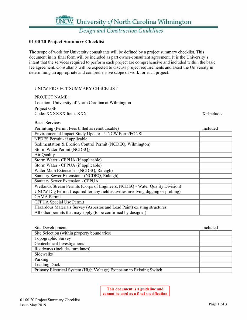
The scope of work for University consultants will be defined by a project summary checklist. This document in its final form will be included as part owner-consultant agreement. It is the University’s intent that the services required to perform each project are comprehensive and included within the basic fee agreement. Consultants will be expected to discuss project requirements and assist the University in determining an appropriate and comprehensive scope of work for each project.
UNCW PROJECT SUMMARY CHECKLIST
PROJECT NAME: Location: University of North Carolina at Wilmington Project GSF Code: XXXXXX Item: XXX X=Included
Basic Services Permitting (Permit Fees billed as reimbursable) Included Environmental Impact Study Update – UNCW Form/FONSI NPDES Permit - if applicable Sedimentation & Erosion Control Permit (NCDEQ, Wilmington) Storm Water Permit (NCDEQ) Air Quality Storm Water - CFPUA (if applicable) Storm Water - CFPUA (if applicable) Water Main Extension - (NCDEQ, Raleigh) Sanitary Sewer Extension - (NCDEQ, Raleigh) Sanitary Sewer Extension - CFPUA Wetlands/Stream Permits (Corps of Engineers, NCDEQ - Water Quality Division) UNCW Dig Permit (required for any field activities involving digging or probing) CAMA Permit CFPUA Special Use Permit Hazardous Materials Survey (Asbestos and Lead Paint) existing structures All other permits that may apply (to be confirmed by designer)
Site Development Included Site Selection (within property boundaries) Topographic Survey Geotechnical Investigations Roadways (includes turn lanes) Sidewalks Parking Loading Dock Primary Electrical System (High Voltage) Extension to Existing Switch
01 00 20 Project Summary Checklist Issue May 2019
This document is a guideline and cannot be used as a final specification
Page 2 of 3
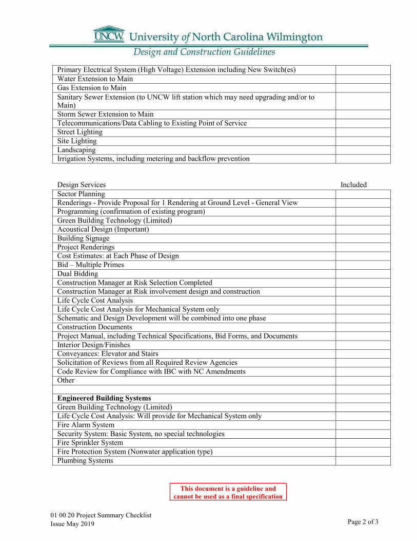
Primary Electrical System (High Voltage) Extension including New Switch(es) Water Extension to Main Gas Extension to Main Sanitary Sewer Extension (to UNCW lift station which may need upgrading and/or to Main) Storm Sewer Extension to Main Telecommunications/Data Cabling to Existing Point of Service Street Lighting Site Lighting Landscaping Irrigation Systems, including metering and backflow prevention
Design Services Included Sector Planning Renderings - Provide Proposal for 1 Rendering at Ground Level - General View Programming (confirmation of existing program) Green Building Technology (Limited) Acoustical Design (Important) Building Signage Project Renderings Cost Estimates: at Each Phase of Design Bid – Multiple Primes Dual Bidding Construction Manager at Risk Selection Completed Construction Manager at Risk involvement design and construction Life Cycle Cost Analysis Life Cycle Cost Analysis for Mechanical System only Schematic and Design Development will be combined into one phase Construction Documents Project Manual, including Technical Specifications, Bid Forms, and Documents Interior Design/Finishes Conveyances: Elevator and Stairs Solicitation of Reviews from all Required Review Agencies Code Review for Compliance with IBC with NC Amendments Other
Engineered Building Systems Green Building Technology (Limited) Life Cycle Cost Analysis: Will provide for Mechanical System only Fire Alarm System Security System: Basic System, no special technologies Fire Sprinkler System Fire Protection System (Nonwater application type) Plumbing Systems

01 00 20 Project Summary Checklist Issue May 2019
This document is a guideline and cannot be used as a final specification
Page 3 of 3
Backflow Prevention Domestic Water Using Metering Hot Water Production Drain, Waste and Vent Systems Natural Gas Systems Medical Gas Systems Laboratory Waste System Laboratory Gas Systems Piping and Insulation Systems Heating, Ventilation and Air Conditioning Systems Exhaust Systems Special Exhaust Systems (Noise issues) Laboratory Exhaust Systems (Hoods) Central Plant Heating and Cooling Central Plant Connections to/from Other Buildings Exterior Building Lighting (Lighting issues) Interior Building Lighting CATV Data/Telecom (Complete System) Data/Telecom (Conduit/Cable Tray, Outlets without connections/wiring) Audio/Visual Systems Power, all voltages Lab Furniture & Fixed Equipment Design & Specifications Furniture - Moveable (Layout Only - No Selection, Procurement, or Bidding) Furniture - Fixed Seating (Selection and Specification) Casework - Fixed Special Inspections Other
Construction Administration Included Architectural = Per Contract (at least 1day per week, and as often as required) MEP Engineering Consultants = Per Contract (at least 1 day per week when trade work is involved) Civil Engineering Consultant = Per Contract (at least 1 day per week when trade work is involved) Other Consultants (min – 1 day per week when trade work is involved) Other Consultants Develop Testing Services Scope of Work Materials Inspection & Testing Developing Commissioning Scope of Work Special Inspections Other
01 00 30 Agency Review Issue May 2019
This document is a guideline and cannot be used as a final specification
Page 1 of 1
01 00 30 Agency Review
Design professionals shall review the requirements of the State Construction Office for all university projects.
The purpose of the State Construction Office is to provide professional architectural and engineering services and management leadership to state agencies. This office carries out its responsibility by (1) processing cost estimates and contracts relating to construction or renovation of state buildings; (2) review and approval of all plans and specifications for the construction or renovation of state buildings; (3) supervision of the letting of all contracts for the design, construction or renovation of state buildings;(4) inspection and acceptance of all work done, and materials used in the construction or renovation ofstate buildings; (5) conducting assessments of state facilities to identify deficiencies and (6) providingadministrative and technical support to the State Building Commission. These services protect the interestof the state and assure the proper expenditure of public funds for the citizens of North Carolina. Thisprovides for efficiency in the expenditure of state funds in its capital improvement program.
Physical Address: New Education Building 116 Mail Service Center Raleigh, NC 27601 Phone: 919-807-4100 Fax: 919-807-4110
Mailing Address: State Construction Office 1301 Mail Service Center Raleigh, NC 27699-1301 Courier Number: 56-02-01
Website: www.nc-sco.com

01 00 40 Construction Detail Schedule Issue May 2019
This document is a guideline and cannot be used as a final specification
Page 1 of 1
01 00 40 Construction Detail Schedule
Part 1: General
1.01 For capital construction projects equal to or greater than one million dollars, the construction schedule shall be in the form of Critical Path Method (CPM) schedule in accordance with the latest version of SCO General Conditions.
1.02 For construction projects, less than one million dollars the construction schedule shall be in the form of either a detailed bar chart or a Critical Path Method (CPM) schedule in accordance with the latest version of SCO General Conditions.

This document is a guideline and cannot be used as a final specification
01 00 50 Room Numbering Issue May 2019 Page 1 of 6
01 00 50 Room Numbering and Wayfinding
Part 1: General
1.01 These standards will allow room numbering and wayfinding procedures to be applied consistently and uniformly to all University buildings.
1.02 Refer also to Section 10 14 00 - Interior and Exterior Signage.
Part 2: When To Apply Room Numbering Standards
2.01 New buildings.
2.02 Renovations where the entire building or large portions of the building are being renovated.
2.03 Smaller renovations where confusion may result from the renovation or where new rooms are created.
2.04 Existing buildings in order to improve clarity and wayfinding.
Part 3: Standards For Room Numbering
3.01 All accessible rooms shall be numbered with a four digit number including but not limited to: electrical closets, mechanical rooms, data rooms, security closets, housekeeping closets, etc.
3.02 Four digit numbers: A. First floor will be numbered “1”, second floor will be “2”, third floor will be “3”, etc.B. Example:
3103 Last three digits indicate room number (Room 103)
First digit indicates floor (3rd floor).
3.03 The following guideline is for numbering stairs:
Name Number Stair A, Level 1 SA01
Stair A, Level 2 SA02
Stair B, Level 1 SB01
Stair B, Level 2 SB02
This document is a guideline and cannot be used as a final specification
01 00 50 Room Numbering Issue May 2019 Page 2 of 6
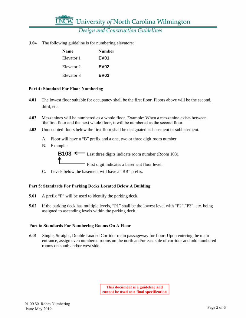
3.04 The following guideline is for numbering elevators:
Name Number Elevator 1 EV01
Elevator 2 EV02
Elevator 3 EV03
Part 4: Standard For Floor Numbering
4.01 The lowest floor suitable for occupancy shall be the first floor. Floors above will be the second, third, etc.
4.02 Mezzanines will be numbered as a whole floor. Example: When a mezzanine exists between
4.03 Unoccupied floors below the first floor shall be designated as basement or subbasement.
A. Floor will have a “B” prefix and a one, two or three digit room numberB. Example:
B103 Last three digits indicate room number (Room 103).
First digit indicates a basement floor level. C. Levels below the basement will have a “BB” prefix.
Part 5: Standards For Parking Decks Located Below A Building
5.01 A prefix “P” will be used to identify the parking deck.
5.02 If the parking deck has multiple levels, “P1” shall be the lowest level with “P2”,”P3”, etc. being assigned to ascending levels within the parking deck.
Part 6: Standards For Numbering Rooms On A Floor
6.01 Single, Straight, Double Loaded Corridor main passageway for floor: Upon entering the main entrance, assign even numbered rooms on the north and/or east side of corridor and odd numbered rooms on south and/or west side.
the first floor and the next whole floor, it will be numbered as the second floor.

This document is a guideline and cannot be used as a final specification
01 00 50 Room Numbering Issue May 2019 Page 3 of 6
6.02 Race Track Plan: Upon entering the main entrance of the building, the lowest room number should be set beginning to the right. Even numbers should be assigned on the right side of the corridor and odd numbers on the left side.

This document is a guideline and cannot be used as a final specification
01 00 50 Room NumberingIssue May 2019 Page 4 of 6
6.03 Rooms Entered Directly from a Corridor: These rooms will be assigned a four digit number with no alphabetical suffix.
6.04 Rooms Entered Via Another Room ,i.e. Suite Arrangement: These rooms will be numbered by the appropriate suite number plus a letter suffix. A. When multiple rooms are located within a suite, the suffix letter for the first interior room
should begin with an “A” and each additional interior room should be given the nextalphabetical designation, i.e., Rooms 1100A,1100B, 1100C, 1100D, etc.
6.05 Reserving Numbers: When numbering rooms off a corridor, numbers should be reserved, i.e. periodically skipped to allow for future growth.
A. These reserved numbers are for use when future renovations or room changes are made in thearea.
6.06 Room Numbers vs. Door Numbers: Room numbers and door numbers are not necessarily the same. Doors are numbered according to the rooms that they access. A room may have multiple doors with each door having its own door number. A room, however, will only have one room number.
Part 7: Simple Renovations
7.01 When an existing interior room (i.e., a room that has no direct access to a corridor) has a new door added giving it direct corridor access, the room number will not change. It will keep its current number with the alphabetical suffix.
This document is a guideline and cannot be used as a final specification
01 00 50 Room Numbering Issue May 2019
Page 6 of 6
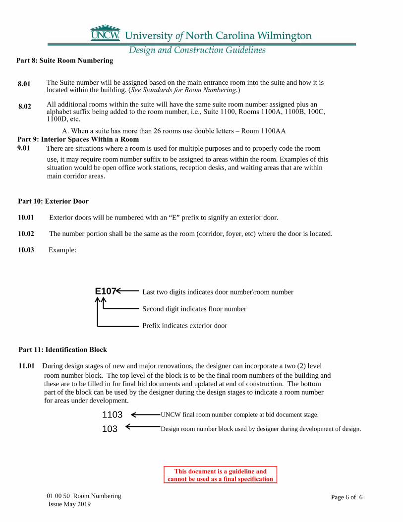
The Suite number will be assigned based on the main entrance room into the suite and how it is located within the building. (See Standards for Room Numbering.)
All additional rooms within the suite will have the same suite room number assigned plus an alphabet suffix being added to the room number, i.e., Suite 1100, Rooms 1100A, 1100B, 100C, 1100D, etc.
A. When a suite has more than 26 rooms use double letters – Room 1100AA
There are situations where a room is used for multiple purposes and to properly code the room use, it may require room number suffix to be assigned to areas within the room. Examples of this situation would be open office work stations, reception desks, and waiting areas that are within main corridor areas.
Part 10: Exterior Door
10.01 Exterior doors will be numbered with an “E” prefix to signify an exterior door.
10.02 The number portion shall be the same as the room (corridor, foyer, etc) where the door is located.
10.03 Example:
E107 Last two digits indicates door number\room number
Second digit indicates floor number
Prefix indicates exterior door
Part 11: Identification Block
11.01 During design stages of new and major renovations, the designer can incorporate a two (2) level room number block. The top level of the block is to be the final room numbers of the building and these are to be filled in for final bid documents and updated at end of construction. The bottom part of the block can be used by the designer during the design stages to indicate a room number for areas under development.
1103 UNCW final room number complete at bid document stage.
103 Design room number block used by designer during development of design.
8.01
8.02
Part 8: Suite Room Numbering
Part 9: Interior Spaces Within a Room 9.01

This document is a guideline and cannot be used as a final specification
01 00 60 Sustainable Design Requirements
Part 1: LEED Certification Requirements
1.01 New projects shall be designed to meet “LEED-Certified” criteria. These include:
A. New BuildingsB. New Additions
01 00 60 Sustainable Design Issue May 2019 Page 1 of 1

01 00 70 Environmental Safety Issue May 2019
This document is a guideline and cannot be used as a final specification
Page 1 of 7
01 00 70 Environmental and Safety Guidelines
Part 1: General
The UNCW Environmental Health & Safety Guidelines are to assist architectural and engineering consultants, contractors and University personnel with the planning, construction and renovation process. Following the Guidelines (which are the minimum acceptable standards) will greatly assist the successful completion of the Project.
The Designer is expected to include the UNCW Health and Safety Requirements in the Contract Documents. These requirements are an additional safeguard to ensure that the construction process is completed in a manner that is fully coordinated with the University, acceptable to the State and also to provide/assist in assuring that each and every construction project is fully safety conscious.
A. Dangerous Chemicals and Liquids:1. Chemical storage/usage areas and flammable liquid storage/usage areas shall be
ventilated sufficiently to remove all fumes and shall be constructed in accordance withapplicable codes to contain vapors and liquids.
B. Doors and Doorways:1. Verify that all glass and glazed doors used at entrances, stairwells, etc. shall have all
adequate push plates or bars and proper glass, as determined by safety and legalrequirements. In general, doors opening into traffic areas shall have vision panels.Classrooms and conference rooms shall be equipped with “Virginia Tech” style doorhardware that allows them to be secured from the inside and the locking mechanism shallbe labeled as to operation.
2. Crashbar hardware shall be installed so that the doors cannot be chained, or cable lockedshut from either side.
3. Doorways in hallways, lobbies and service rooms such as vending or recycling shall havea magnetic hold open devices connected to the fire protection system.
4. No doorstops or props shall be installed in the construction.C. Site Safety Access
1. Site lighting shall meet university lighting and uniformity standards.2. Bollards should be able to be removed by a single person3. Service sidewalks should be sufficient to support a fire apparatus4. Each address shall have a retroreflective address sign with letters no less than 4 inches high
with the address and building name.
1.01
2.01
Part 2: Responsibilities
2.02 Guidelines:

01 00 70 Environmental Safety Issue May 2019
This document is a guideline and cannot be used as a final specification
Page 2 of 7
A. Windows1. Windows should have hinged screens to prevent the screens from being easily removed by
occupants.2. Windows that open less than 18 inches are preferred to prevent falls.3. Impact resistant film is preferred on all buildings that are identified as specialized
or critical.B. Fire Extinguisher Cabinets:
1. Fire extinguisher cabinets should be recessed or semi-recessed non-locking cabinetseither brushed aluminum or white in color.
C. Fire Safety:1. Fire Department Connections should be located within 100 feet of a fire hydrant and
be accessible without driving on sidewalks, across grass or jumping curbing. Hydrantsshall have a “storz” quick connect on the side facing the roadway and shall have two 2.5-inch hose connections. All threads shall be national standard threads. Mueller is thepreferred manufacturer.
2. No structure should be more than 300 feet from the nearest fire hydrant.3. All new building should have framed 8.5x11” areas near each entrance where evacuation
plans can be posted.4. Fire Department connections shall be a “Storz” connection with a 45-degree downturn
and clearly labeled with a sign (stating what building it supplies) that isretroreflective and red and white in color.
5. Sprinkler valves shall be post indicator valves and not OS&Y valves.6. Kitchen layout shall be sufficient that a smoke detector is not required in the kitchen area
as these increase nuisance alarms.7. Knox Box fire alarm key boxes keyed to Wilmington Fire Department access
shall be installed on the main entrance of each building.8. Fire evacuation plan sleeves shall be installed near the elevator on every floor and
in major areas of assembly.9. Fire Exit signs shall be LED bulb signs.10. Emergency lighting integrated into existing lighting through batteries or generators are
preferred to battery supplied surface mounted exit lights.D. Support Areas:
1. Every building should have a room or room designated for mail, recycling andvending. We receive frequent citations for these materials being placed in hallways orstairwells so therefore they should not be located in hallways.
2. Attic access areas shall be lockable and fitted with a university standard key3. No garbage chutes shall be utilized inside any buildings unless there are extraordinary
circumstances.
01 00 70 Environmental Safety Issue May 2019
This document is a guideline and cannot be used as a final specification
Page 3 of 7
4. Any void spaces large enough to be entered shall be fitted with doors andventilation provided to the area.
H. Exterior Water Fountains:
1. Fountains should be drained to the sanitary sewer. If they are vandalized with chemicalsor soaps we cannot discharge these to the storm sewer.
I. Interior Drinking Fountains:1. Drinking fountains shall be fitted with a water bottle fill station.
J. Roof Drains.1. Roof drains shall have guards to prevent clogging and shall have overflow drains
in parapet walls.2. External gutters are preferred above internal roof drains, but where utilized there shall be
cleanouts at the roof and ground level and they shall be of non-metallic construction.K. HVAC
1. No ground level (below 24 inches) or service area air intakes are allowed.2. No internally insulated or fiberboard ductwork shall be utilized.3. UV light disinfection shall be provided for large-scale coils.4. Humidity and temperature sensors that report to building automation system.5. If windows are operable, supply air delivery located away from windows.6. All air handlers shall be fully accessible for maintenance without having to cut drywall.7. There shall be a dedicated exhaust for laundries8. Range hoods and bathroom vents shall vent directly outdoors.9. CO meters shall be provided in all areas where fuel powered equipment is utilized
L. Walls and Surfaces1. All ceiling penetrations (i.e. ductwork, smoke detector heads, etc.), must have a seal
between the device and the interstitial spaces.2. Solid surface counters shall be utilized in kitchen and bathrooms3. Wet areas (kitchen, bath, laundry, water heater) have adequate water retention such as
cupped floors or welded seams4. Sheetrock to have ½” gap minimum from floor and mold resistant “green board” shall be
utilized in all bath, laundry, kitchen stairwell, and service areas.
01 00 70 Environmental Safety Issue May 2019
This document is a guideline and cannot be used as a final specification
Page 4 of 7
Part 3: Scope:
3.01
These requirements are designed to ensure that contractors working for UNCW, on projects under the supervision of the Construction Department, take adequate steps toward the following:
A. Set the expectation that contractors comply with federal, state, and local environment, and safety regulations.
B. Provide the contractor’s employees and UNCW employees a safe working environment.C. Protect UNCW from losses due to property or environmental damage.D. Protect UNCW from liability.
Part 4: Responsibilities
4.01 It is the contractor’s responsibility to:
A. Conduct work in accordance with federal, state and UNCW safety/environmental regulationsB. Inform subcontractors of these requirements and ensure that they follow themC. Complete the attached Contractor/Project Data SheetD. Install barricades to delineate the boundaries of the work areasE. Post signs to warn of dangers and to identify protective equipment required in the work zoneF. Maintain proper egress requirements from UNCW buildingsG. Establish and maintain their own Safety and Health ProgramH. Immediately correct unsafe conditions that are a result of contractor activitiesI. Provide SDSs for hazardous materials that you use onsite
J. Notify the UNCW Construction Project Manager as soon as practicable if any of the following conditions occur so that they can consult with EH&S1. An unsafe condition Exists on the site that is not that is not a result of contractor activities2. An accident results in damage to UNCW property3. You anticipate the interruption of fire alarm, sprinkler system or any utilities
Deb Tew, Associate Director, Environmental Health & Safety Phone: (910) 962-7017 Fax: (910) 962-3473 E-mail: [email protected]
3.02
UNCW Environmental Health & Safety Requirements
01 00 70 Environmental Safety Issue May 2019
This document is a guideline and cannot be used as a final specification
Page 5 of 7
K. Notify UNCW EH&S and Construction Project Manager the immediately if thefollowing occur:1. Unanticipated interruption of fire alarm, sprinkler system or utility
interruption2. Spills or leaks of any hazardous substance that occurs on the worksite3. An accident occurs that results in death or the injury of three or more persons
4.02 Failure to comply with these requirements can result in termination of the contract. A. It is the UNCW Construction Project Manager’s responsibility to:
1. Ensure the EH&S in invites to all pre-construction meetings2. Ensure that contractors complete a Contractor/Project Data Sheet3. Be primary contract with the contractor in environmental, health and safety concerns4. Call the contractor’s attention to unsafe acts or conditions that they observe5. Inform EH&S if they have been notified of any conditions that warrant further
investigation to prevent accident occurrences, environmental damage orregulatory fines
B. It is the UNCW EH&S Department’s responsibility to:1. Be present to explain these requirements at pre-construction meetings2. Provide contractors with emergency information phone numbers3. Notify the UNCW Construction Project Manager of unsafe acts or conditions
observed4. Notify the contractor if any conditions observed that are immediately dangerous to
life, health or environment5. Provide the contractor with SDSs for hazardous materials used by UNCW in the area
where they are working.

01 00 70 Environmental Safety Issue May 2019
This document is a guideline and cannot be used as a final specification
Page 6 of 7
UNCW Contractor/Project Data Sheet Contractor Information Company Name: Address: Business Phone Number: Emergency 24-hr Phone: Contractor Project Contact:
UNCW Construction Project Manager Project Manager: Phone:
Emergency Phone:
Project Information Building Where work Conducted: Location of Work:
Brief Description of Work to be Performed:
Date Work is Expected to Begin: Expected Completion: Expected Work Schedule (Days of weekend hours):
EH&S Department Information: Fire, Medical and Police: 4911 on-campus phone system or (910) 962-4911 from other phones
EH&S Phone Number: (910) 962-3057 EH&S Emergency phone 4911
Scope of Work Questionnaire (are the following activities taking place on site)
Activity Yes No Excavation and trenching Asbestos abatement Confined space entry Cranes or hoist Lockout/Tagout Fuel storage tanks Generate hazardous waste Modify sprinkler system Use fall protection equipment Use compressed gas cylinders
01 00 70 Environmental Safety Issue May 2019
This document is a guideline and cannot be used as a final specification
Page 7 of 7
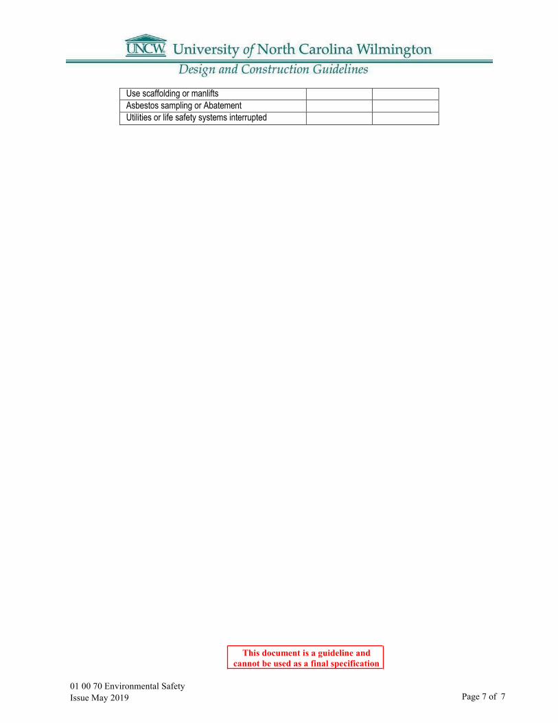
Use scaffolding or manlifts Asbestos sampling or Abatement Utilities or life safety systems interrupted

Page 1 of 1 01 00 75 Construction Sign Issue May 2019
This document is a guideline and cannot be used as a final specification
01 00 75 Construction Project Sign
1.01 A construction project sign will be provided by the University using the template below. A. Warning signs should be used as needed and should include a sign stating “NOINTERACTION WITH STUDENTS VIOLATORS WILL BE IMMEDIATELYDISMISSED."
B. Contractors must supply signage identifying their company at the entrance and exit ofthe construction site.
C. All other temporary construction site signage and other informational signage must bekept to a minimum.
This document is a guideline and cannot be used as a final specification
01 00 80 Digging and Excavation
Part 1: Purpose
1.01 To provide guidelines for digging and excavation operations on university property.
1.02 Scope A. Applies to all university departments and activities, as well as other persons on university
property.B. Applies to ALL penetrations of soil on university property accomplished with
shovels, backhoes, trenchers, axes, posthole diggers, tent stakes, or ground rods.
1.03 Policy A. General Statement:
1. In accordance with North Carolina Occupational Safety and Health (NCOSHA)standards, any individual who has a need to dig or excavate on university property mustreceive written permission from the UNCW Architectural and Construction Servicesbefore commencing digging or excavation operations. The Architectural andConstruction Services is responsible for ensuring that all applicable regulations arefollowed during any digging/ excavation processes performed by Physical Plantemployees or by any personnel contracted by the Director of Physical Plant. When otherlabor is used, the person(s) conducting the digging/excavation operations are responsiblefor ensuring all applicable regulations are followed.
Part 2: UNCW Digging and Excavation Manual
2.01 Responsibility for Damages A. Any persons or organizations digging without proper authorization will beresponsible forrepair costs to damaged underground utilities
2.02 Procedures A. Person(s) desiring to dig on university property must complete and submit a Digging and
Excavating Request form and an area sketch to the UNCW Architectural and ConstructionServices a minimum of fourteen (14) working days in advance of the proposed diggingoperations to allow for proper clearance and investigation.
B. The Digging and Excavating Request form can be found athttp://www.uncw.edu/physicalplant/forms.html.
01 00 80 Digging and Excavation Issue May 2019 Page 1 of 1

This document is a guideline and cannot be used as a final specification
01 00 90 Supplementary Conditions Issue May 2019 Page 1 of 6
01 00 90 UNCW Supplementary General Conditions
Article 1 –DEFINTIONSParagraph "a": Add the following to the end of the paragraph: "The Geotechnical Technical Report does not constitute part of the Contract Documents but is included for reference." Add the following Subparagraph c. "c. Add “the designers are (insert designer name)”. Add the following Subparagraph h. "h. “The project name is (insert project name).” Add the following Subparagraph u. "u. Project Identification: All correspondence, reports, schedules, applications for payment, fax items, etc. shall contain proper title of project, code, item and SCO ID numbers, typical," Paragraph "cc": Add the following new paragraph: “Latest edition” shall mean the current printed version of the referenced document issued up to 30 calendar days prior to date of receipt of bids, unless specified otherwise. Paragraph "dd": Add the following new paragraph: “Drawings” or "plans" shall mean the drawings enumerated in the contract documents, as well as all the information in the detail manual (when applicable), addenda, and designer-prepared field drawings and clarification drawings. Paragraph "ee": Add the following new paragraph: “Specifications” mean this project manual and addenda thereto. ARTICLE 2- INTENT AND EXECUTION OF THE DOCUMENTS Paragraph "a": Add the following new sub-paragraphs:
1. These drawings and specifications represent the general dimensional and aestheticrequirements for various "in place" materials required to produce {insert project type here}acceptable to the owner for his intended use.
2. It is the intent of these drawings and specifications to provide {insert project type here} andassociated appurtenances that are structurally sound and conforming to at least the minimumrequirements of the North Carolina State Building Code.
3. The Contractor shall make all reasonable efforts to achieve this intent. If any detail shownon these drawings appears inconsistent with this intent, in the opinion of the Contractor, heshall notify the Designer in writing of his opinion and await instructions from the Designerbefore proceeding with the work.
4. Where more detailed information is needed, or when an interpretation of the contractdocuments is required, the Contractor shall refer the matter in writing to the Designer priorto proceeding with the work. The Designer shall furnish the Contractor an interpretation inwriting.
5. If the Contractor discovers errors, inconsistencies, discrepancies or omissions in the contractdocuments, the Contractor shall inform the Designer of such condition prior to proceedingwith the work.
6. If the Contractor discovers errors, inconsistencies, discrepancies or omissions in the contractdocuments prior to bid, the Contractor shall request clarifications from the Designer andshall include in the bid price all work required to deliver a fully operational and ready to usesystem.
7. If inconsistencies, discrepancies or contradictions in the Contract Documents are discoveredafter the bid, the Contractor shall be deemed by submittal of his bid, to have bid the mostcostly as to labor, materials, duration, sequence and method of construction to provide thework.”
01 00 90 Supplementary Conditions Issue May 2019 Page 2 of 6
This document is a guideline and cannot be used as a final specification
ARTICLE 3 - CLARIFICATION AND DETAIL DRAWINGS Paragraph "a": Add the following to the end of the paragraph: “If errors, inconsistencies or discrepancies in the contract documents are discovered by the Contractor, the Contractor shall inform the designer of such condition prior to proceeding with the work. The designer shall furnish the Contractor written clarification in a reasonable time, so as not to impact the progress of the work. ARTICLE 5 - SHOP DRAWINGS, SUBMITTALS, SAMPLE DATA Paragraph "c": Add the following new paragraph: “This schedule must account for any resubmittals required to obtain approval from the Project Designer and Owner.” Paragraph "d": Add the following new paragraph: “No time extension will be granted for delays caused due to failure of the Contractor to properly review shop drawings prior to submittal to the Project Designer. All shop drawings shall indicate how materials relate to conditions of the project. Standard manufacturer's drawings that do not show how and where material is to be used will not be reviewed by the Project Designer. Shop drawings shall not be reproductions of contract documents. Coordination drawings are required in accordance with Article 14.” Article 8-MATERIALS, EQUIPMENT,AND EMPOLYEES Add the following to Subparagraph f: "f. "The designer is the judge of equivalency of materials, products, equipment, assemblies, or installation methods proposed by the Contractor as equivalent to those specified," Paragraph "g": Add the following to the end of the paragraph: “All construction personnel shall be respectful to all University of North Carolina at Wilmington staff and students. Any disrespect, harassment, unwelcome comments or advances from any construction personnel toward any staff member or student shall constitute sufficient grounds for University of North Carolina at Wilmington to request removal of any specific individuals from this project. Such action taken by the Owner shall not constitute grounds for a delay claim. The Owner will not be responsible for any delays caused to the project due to any individual being removed from the project. Project superintendents shall be held accountable for any incident of this nature.” ARTICLE 10- PERMITS, INSPECTIONS, FEES, REGULATIONS Paragraph “f”: Add the following paragraph: Notify UNCW EH&S a minimum of one day in advance prior to performing work requiring a Hot Work Permit.“ ARTICLE 11- PROTECTION OF WORK, PROPERTY, AND THE PUBLIC Paragraph "j": Add the following paragraph: “In case emergency contact is required, the Contractor shall furnish the Owner with names, pager numbers, and telephone numbers (day and night) of the project manager and superintendent. The numbers shall remain current for the duration of the project and shall be updated as required.” Paragraph "k": Add the following paragraph: “The Owner will provide security as it deems prudent and necessary for its own protection. The Contractor shall be responsible for security and safety of the project within the project limits, including on-site materials. The Contractor and the Owner shall meet on a regular basis as required but not less than weekly to coordinate safety and security issues.”

01 00 90 Supplementary Conditions Issue May 2019 Page 3 of 6
This document is a guideline and cannot be used as a final specification
Paragraph "l" Add the following paragraph: “The Owner will conduct normal operations during the duration of the project. Unless otherwise stated, the campus buildings will be occupied and will operate on a normal schedule. This means that the Contractor will be required to schedule work around regular operations, special events, visitors and staff requirements. The Contractor shall coordinate with the Owner's representative to minimize any disruptions to the functions of the College.” ARTICLE 12- SEDIMENTATION POLLUTION CONTROL ACT OF I973 Paragraph "e": Add the following new paragraph: “The Contractor shall comply with the following requirements: Equipment utilized during the construction activity on a site must be operated and maintained in a manner as to prevent the potential or actual pollution of the surface or ground waters. Fuels, lubricants, coolants, and hydraulic fluids, or any other petroleum products, shall not be discharged on the ground or into surface waters. Spent fluids shall be disposed of in a manner so as not to enter the waters, surface or ground, and in accordance with applicable state and federal disposal regulations. Any spilled fluids shall be cleaned up to the extent practicable and disposed of in a manner so as not to allow their entry into the waters, surface or ground, storm sewers, or drains on private or public property. Herbicide, pesticide, and fertilizer usage during the construction activity shall be restricted to those Materials approved by EPA and shall be used in accordance with label instructions. All wastes composed of construction materials shall be disposed of in accordance with NC General Statutes, Chapter 130A, Article 9- Solid Waste Management, and rules governing the disposal of solid waste (NC Administrative Code Section l5A NCAC 13B).” Paragraph "f": Add the following new paragraph: “Minimum Monitoring and Reporting Requirements
1. All sedimentation and erosion control of facilities shall be inspected by the Contractor at least once every seven calendar days and within 24 hours after any storm event of greater than 0.5 inches of rain per 24-hour period.
2. Storm water runoff discharges shall be inspected by visual observation for color, foam, outfall,staining,visible sheens, dry weather flows and muddy water (at the frequency described above) to evaluate the effectiveness of the pollution control facilities or practices. If any visible off-site sedimentation is leaving the site, corrective action shall be taken to reduce the discharge of sediments.
3. The Contractor shall submit to the Owner a written report of weekly inspections. In accordance with NCDEQ requirements and utilizing the self-inspection and monitoring forms. Visible sedimentation found off the site shall be recorded with a brief explanation as to the measures taken to prevent future releases as well as any measures taken to clean up the sediment that has left the site. This record shall be made available to Department of Environmental Management or authorized agent upon request.
4. Paragraph"g": Add the following new paragraph: “Maintenance and Inspections The Contractor shall keep all erosion controls devices and materials in good repair. If inspections required by this permit identify a need for maintenance of control measures, modifications or additions to control measures, or corrective actions to control sediment or other pollutants these actions must be performed as soon as possible and before the next storm event to maintain the effectiveness of the control measures. The Owner reserves the right to deduct the cost of maintenance, modifications, additions or corrective actions from the Contractor's application for payment.
5. The owner's representative may periodically evaluate the project for compliance with these requirements.”

01 00 90 Supplementary Conditions Issue May 2019 Page 4 of 6
This document is a guideline and cannot be used as a final specification
Article 14-CONSTRUCTION, SUPERVISION, and SCHEDULERevise Subparagraph e to read as follows: "e. " In such case, the engineer or land surveyor shall coordinate the project benchmark with known campus benchmarks." ARTICLE 15 – SEPARATE CONTRACTS AND CONTRACTOR RELATIONSHIPS Paragraph "g": Add the following new paragraph: E-Verify Compliance: Pursuant to Session Law 2013- 418, Contractor shall fully comply with the U.S. Department of Homeland Security employee legal status EVerify requirements for itself and all its subcontractors. Owner requires an affidavit attesting to Contractor’s compliance. Violation of the provision, unless timely cured, shall constitute a breach of contract. ARTICLE 23 -TIME of COMPLETION. DELAYS. EXTENSION. Add the following: Paragraph "h. "Time. 1. The Contractor shall commence work to be performed under this agreement on a date to be specified in a written order form the designer and shall fully complete all work within {insert time here} consecutive calendar days from and including said date. For each day in excess of the above number of days, the Contractor shall pay to the Owner the sum of {insert LD amount here} as liquidated damages reasonably estimated in advance to cover the losses to be incurred by the Owner by reason of failure of said Contractor to complete the work within the time specified, such time being in the essence of this contract and a material consideration thereof." Paragraph "i": Add the following new paragraph: “Working hours: The Contractor shall establish a working hour and date schedule and submit to the Owner’s representative for approval. Any deviations from this schedule shall be requested from and approved by the Owner at least five (5) work days in advance.
1. The Contractor shall agree to additional restrictions on working hours and days as may be enforced bythe Owner during certain periods of the year such as, but not limited to, the week of final exams andmove in for each semester.2. Working hours {insert working hours}
ARTICLE 31 REQUEST for PAYMENTAdd the following: “f. Contractor shall submit to the Designer a request for payment on AIA Document G702 unless otherwise approved by the Designer”

01 00 90 Supplementary Conditions Issue May 2019 Page 5 of 6
This document is a guideline and cannot be used as a final specification
ARTICLE 38 – USE OF PREMISES Paragraph "e": Add the following new paragraph: “Storage of construction materials shall be limited to the staging area, as defined in the contract documents.”
Paragraph "f": Add the following new paragraph: “Where equipment must cross walks, landscaping areas, or ramps, the Contractor shall provide ¾” plywood sheets for protection of these areas. Cross walks, landscaping areas, or ramps damaged by construction activity shall be repaired or replaced.”
Paragraph "g": Add the following new paragraph: “The construction site and staging areas as well as Owner’s adjacent campus areas shall be kept free of trash, litter, and debris at all times.”
Paragraph "h": Add the following new paragraph: “Grass in the construction site shall be mowed as often as required to maintain a neat appearance. Tree protection shall extend at least to the drip line of the trees to be protected. Unless otherwise shown on the drawings, minimum tree protection shall include four-foot landscaping fencing supported with steel stakes four foot on center. Al l areas under the drip line of trees are off limits to vehicular traffic unless protected by plywood.”
Paragraph "i": Add the following new paragraph: “Landscape protection when required, shall be installed prior to the initial grading stage. No storage of any kind, access, or activity of any kind will be permitted inside the landscaping protection areas.”
Paragraph "k": Add the following new paragraph: “When required by the drawings, a construction fence shall be installed. The fence shall be construction of heavy-duty chain link material, with screening fabric or privacy slats , and have a minimum height of six feet and it shall have a continuous top tubular rail. Swing gates shall be included at all and every access to the enclosed area.” ARTICLE 39 - CUTTING AND PATCHING Paragraph "d": Add the following new paragraph: “All cutting, and patching required to perform the work, and to install the specified products under a particular contract shall be performed under that particular contract. All patching work shall be made by craftsmen skilled in the required work on who may already be engaged on the project. All painting within previously painted areas shall be painted by the contract which caused the need for this painting, unless new finishes have been scheduled. All painting shall be by skilled painters who may already be engaged on the project.”

01 00 90 Supplementary Conditions Issue May 2019 Page 6 of 6
This document is a guideline and cannotbe used as a final specification
ARTICLE 40 -UTLITIES. STRUCTURES. SIGNS. Subparagraph “a” to read as follows: "The contractor shall provide necessary and adequate facilities for water, electricity, gas, oil sewer, and other utility services which may be necessary and required for completion of the project. The University owns the water, sewer, gas, telephone and electrical utilities on campus. The contractor shall arrange for and provide all appurtenances necessary for the provision of temporary services, including connections to existing utilities. Temporary telephone service shall be obtained and paid for by the contractor through the University's telecommunications department. Connections for all other utilities shall be performed under the supervision of Physical Plant personnel. In all cases, the contractor shall give a minimum of 72 hours’ notice for the connection of all utilities. The Contractor shall provide temporary electric, gas and water meters on University-owned utility services to the building. The University will read the meters on a monthly basis and will pay for the cost of consumption for these utilities. The University reserves the right to back charge the contractor if the University finds negligence in the use of utilities. Charges for telephone and data utilities will be charged to the contractor directly by UNCW Telecommunications Department on a monthly basis. Contractor is advised to confirm current telephone and data rates with UNCW Telecommunications Department (910 962-4019). Add the following to item j.: "General Contractor shall provide his own office facility including telephone and facsimile machines required at location on site approved by the Architect and Owner. The Office shall be weather-tight with lighting, electrical outlets, heating, cooling equipment and equipped with sturdy furniture, drawing rack and drawing display table. The office shall also include a desk and telephone/data outlet. General Contractor's office shall be large enough for his own use and for use as a coordination office to include meeting space with table and chairs for 16 people. Portable toilets must be provided on site. The Owner's toilet facilities shall not be used at any time during the project." Paragraph “m": Add the following new paragraph: “It is imperative that Owner’s utilities and other services be maintained at all times except for scheduled interruptions. Any necessary utility interruptions shall be approved by the Owner's Representative at least three weeks in advance. If necessary, work shall be performed at night, over the weekend, or during holidays. No extra payment will be made for such work. When utility services cannot be interrupted for the length of time required, the Contractor shall make provisions for temporary services. Pedestrian traffic around the construction limits must be maintained in a clean and safe condition at all times.” ARTICLE 42 – GUARANTEE Add the following: “e. All warranty periods to be begin at “Final Acceptance” date rather than at the “Substantial Completion“ date.” ARTICLE 45 – TAXESAdd the following: "e. Contractors shall submit monthly with their request for payment, a signed statement containing the amount of sales and use tax paid by the Contractor for that particular billing period on the documents included in the project specifications.”
END OF UNCW SUPPLEMENTARY GENERAL CONDITIONS
01 10 10 CAD Standards Issue May 2019
This document is a guideline and cannot be used as a final specification
Page 1 of 2
01 10 10 CAD Standards
Part 1: Overview:
1.01 These Guidelines are issued to promote the development of AutoCAD drawings suitable for use in the University of North Carolina Wilmington’s Office of Facilities CAD environment. Electronic drawings produced and submitted in accordance with these guidelines have significantly greater value to the institution, helping to provide consistency and compatibility with existing AutoCAD documents. Architects, Engineers, Design Professionals and Contractors delivering AutoCAD documentation to UNCW must ensure these guidelines are reviewed and understood by those persons responsible for preparing AutoCAD drawings. All AutoCAD drawings forwarded to UNCW shall be submitted in a timely fashion, coinciding with the needs of the project and UNCW staff. The delivery of AutoCAD documentation during various project stages shall be timed appropriately to ensure that UNCW ultimately receives the most accurate information available. The receipt of electronic AutoCAD drawings alone does not alleviate the responsibility of the Architect, Engineer or Consultant of providing original signed and sealed hard copy documentation to UNCW.Other UNCW contracts or construction documents may reference this document.
Part 2: Drawings
2.01 Formats: A. UNCW requires that all project drawings be created and submitted using AutoCAD (.dwg file
extension) software. AutoCAD version 2008 or newer up to version 2015 is required.
2.02 Drawing Content: A. Prior to submitting drawings to UNCW, AutoCAD files containing multiple drawing sheets
shall be broken down into separate drawings containing single sheets. Multiple layout tabsare not to be used.
B. The drawing file name shall match the drawing number on the title bar.C. The proper layer state shall be restored for each drawing submitted.D. All CAD drawings shall be purged of empty, unused, or non-essential drawing data.E. All externally referenced data (XREF’s) that were used in the Cad drawings shall be inserted
and bound, using the “bind” command.1. Bound XREF’s shall have their layers intact.
F. No CAD drawings that contain xref’s will be accepted.G. Each final submitted drawing sheet shall have “As-Built” or “Record Drawing” clearly
marked on every electronic and printed sheet.H. Text styles and fonts may vary, however, custom fonts and hatch styles not packaged within
AutoCAD are not permitted.I. All blocks must be created on layer “0”. Nested blocks should be avoided.
01 10 10 CAD Standards Issue May 2019
This document is a guideline and cannot be used as a final specification
Page 2 of 2
J. All objects, layers and line types must be defined as “BYLAYER”.
2.03 Model and Paper Space Usage: A. The primary drawing(s) shall be created in model space.B. All drawings created within model space must be drawn to full size (1:1 scale).C. Any additional items such as details, dimensions, elevations, or sections should be drawn to
full scale in model space.D. General project graphic elements such as title blocks should be drawn in paper space.
Elements such as legends, schematics, key plans, diagrams and notes may also be drawnin paper space.
E. Scale objects using paper space viewports – zoom viewports to the appropriate scale.F. Label scale of each viewport in paper space.G. Viewports should be created on a “viewport” layer.
Part 3: Drawing Submittal Requirements:
3.01 General: A. Include a transmittal sheet with submittals indicating UNCW project number, UNCW
project name and a complete list of all materials submitted.B. Deliver one set of original signed and sealed hard copy prints along with the electronic
drawing submission. All electronic drawings shall be submitted on a CD/DVD, USB Driveor transmitted electronically. These drawings should be labeled with project name, type ofdrawing package (i.e. bid set, construction drawings, record drawings), and date created.
C. All content of the electronic drawings must match the delivered hard copy version. Theelectronic file should look exactly like the hard copy version when the file is opened byUNCW personnel.
3.02 As-Built Submittal Requirements: A. On completion of the project the Designer is responsible for providing a signed and sealed
complete set of drawings to UNCW. Mark all drawings with ‘As-Built’ (for completed andfinal submittals of a new building or new building addition drawing set) or ‘RecordDrawings’ (for final submittal of drawings of remodeling projects, shop drawings and siteworks) and subscribe to the previously recommended CAD standards.
B. Designers are responsible for incorporating any changes in the field submitted by theContractors into the final drawings. Scans of the Contractor’s hard copy as-built drawingswill not be accepted.
01 10 15 Specifications StandardsIssue May 2019
This document is a guideline and cannot be used as a final specification
Page 1 of 1
01 10 15 Specification Standards
Part 1: General
1.01 Specification Format:
A. Specifications shall be organized based on the latest “Master Format” version.
1.02 Specification Content: A. The Designer shall:
1. Make every effort to ensure that the specifications are as clear and unambiguous aspossible.
2. Review specifications to be thoroughly coordinated.3. Conduct a thorough in-house review, of all disciplines, to eliminate conflicting
requirements.4. Verify that the responsibilities that must be fulfilled by the Contractor or by others
are clearly delineated and that it encompasses all work required to provide a finishedand usable product. There should be no ambiguous terminations where one trade orContractor stops, and another begins.
1.03 Product Choices: A. A minimum of three manufacturers must be provided for each product specified.B. When specifying a product, always provide the actual manufacturer name. The local
representative or distributor contact information may be provided as additional information.C. Verify that materials specified are current and available.D. Verify model numbers provided are current.E. Identify if a chosen product option is standard or custom.

04 00 00 Masonry Issue May 2019
This document is a guideline and cannot be used as a final specification
Page 1 of 6
04 00 00 Masonry General Requirements
Part 1: Brick Veneers
1.01 Face Brick: Basis of Design: Statesville Brick Company “Red Royal Special”
1.02 Mortar And Grout Materials A. Mortar color shall be light grey. Basis of Design is masonry cement by Giant in
standard grey color to match existing mortar on campus.B. Mortar joint shall match existing on campus.
1.03 Expansion Joints A. If possible, locate the expansion joints behind the
downspouts.1. See Section 07 92 00 Joint Sealants
1.04 Cold Weather Provisions A. Specify cold weather construction provisions when construction schedule indicates cold
seasonal conditions will be likely.
Part 2: Embedded Flashing Materials
2.01 Hidden from view: Copper-Laminated Flashing: 5-oz./sq. ft. copper sheet bonded with asphalt between 2 layers of glass-fiber cloth. Use only where flashing is fully concealed in masonry.
2.02 Exposed to view: Through-wall flashing that projects out from face of wall shall be 16 oz. copper.
Part 3: Miscellaneous Masonry Accessories
3.01 Weep-Prefab: A. Basis of Design: Wire-Bond #3601 “Cell Vent”
1. Size: 3/8” wide x 2-1/2” high x 3-3/8” long2. Color: Clear3. Material: Polypropylene copolymer
3.02 Cavity Drainage Material: Free-draining mesh, made from polymer strands that will not degrade within the wall cavity. Strips, full-depth of cavity and 10 inches wide, with dovetail-shaped notches 7 inches deep that prevent mesh from being clogged with mortar droppings.
Part 4: Brick Screen Walls4.01 Pierced brick walls and brick columns. Columns to have precast caps. Height as necessary to hide
items being enclosed. Wall width to be 12” and columns to be 24”x 24”.
04 00 00 Masonry Issue May 2019
This document is a guideline and cannot be used as a final specification Page 2 of 6
Part 5: Drawings
5.01 Indicate on the drawings the following information related to Unit Masonry: A. Extent of each type of engineered and empirically designed masonry and delineate, as
required, to show dimensions (nominal thickness, cavity width, setting bed thickness, etc.)and construction (single wythe, multi-wythe, composite, cavity, etc.).
B. Details of anchors, ties, reinforcing, joint reinforcement, lintels, chases, and recessesor openings for other construction.
C. Colored mortar, if any. Indicated as either “Colored Aggregated Mortar” or“Pigmented Cement Mortar.”
D. Pattern bonds for exposed surfaces, if other than running bond.E. Structural bonding between wythes (continuous wire reinforcing) and spacing of same.F. Extent of insulation for cavity walls and in hollow units.G. Location of movement joints and details of each type of movement joint. Show
isolation joints between masonry and concrete, and masonry and steel framing, if any.H. Location, types, and details of items to be built into masonry such as anchors, ties,
inserts, lintels, flashing, reglets and insulation nailers.I. Details of special bearing areas (particularly for hollow unit masonry) showing extent and
type of high-strength units, such as solid CMU areas in hollow CMU walls, grout or concretefill for hollow CMU, bond beams, and other special construction required for structuralbearing.
J. Details of masonry lintels if construction exceeds nominal construction specified.K. Details of special masonry features for walls, such as chases and recesses and openings for
other work.L. Fire resistance ratings (4-hour, 3 hour, etc.) if any.
Part 6: Reference Design Standards
6.01 Typical Masonry Details A. Jack ArchB. Brick QuoinsC. Masonry openings for WindowsD. Cast stone sill
6.02 See also UNCW Original Campus Construction Documents.
Part 7: Reference drawings and photos:
7.01 See next pages for related details taken from Original Campus Construction drawings.
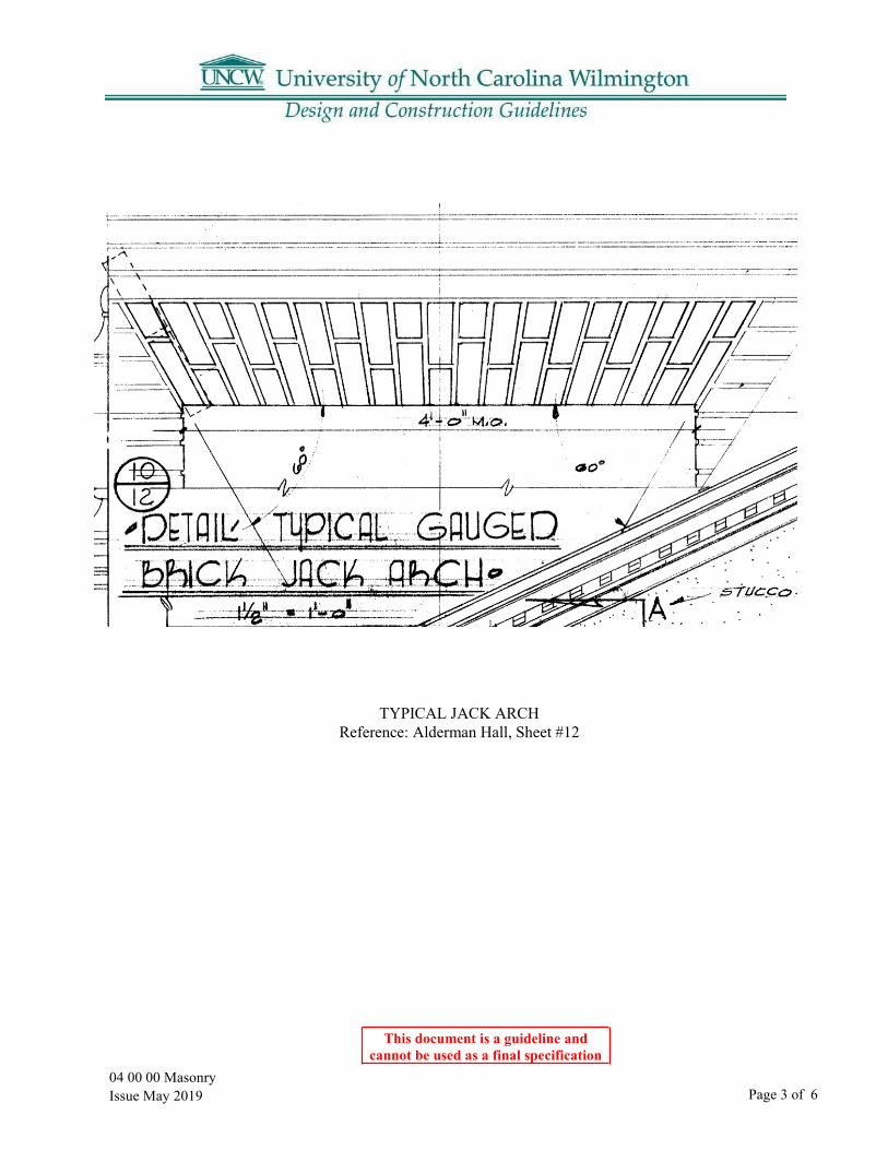
04 00 00 Masonry Issue May 2019
This document is a guideline and cannot be used as a final specification
Page 3 of 6
TYPICAL JACK ARCH Reference: Alderman Hall, Sheet #12
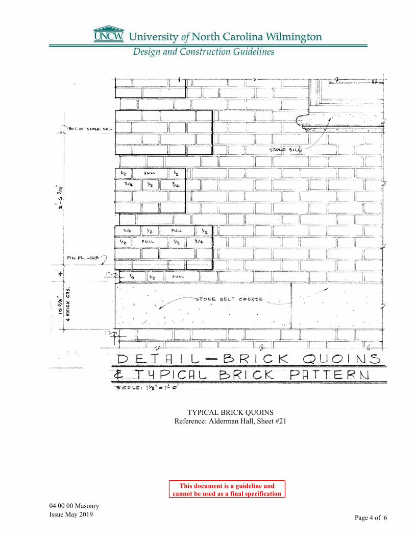
04 00 00 Masonry Issue May 2019
This document is a guideline and cannot be used as a final specification
Page 4 of 6
TYPICAL BRICK QUOINS Reference: Alderman Hall, Sheet #21
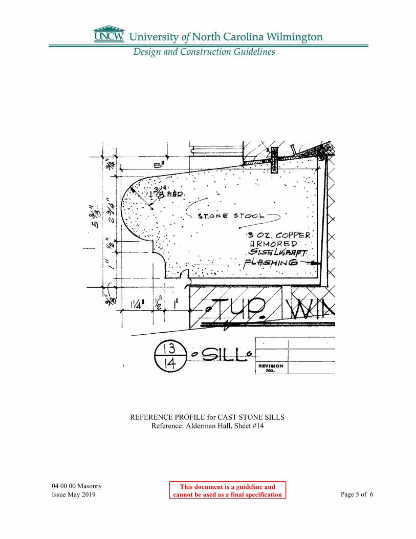
04 00 00 Masonry Issue May 2019
This document is a guideline and cannot be used as a final specification Page 5 of 6
REFERENCE PROFILE for CAST STONE SILLS Reference: Alderman Hall, Sheet #14
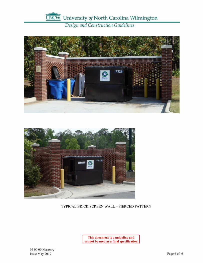
04 00 00 Masonry Issue May 2019
This document is a guideline and cannot be used as a final specification
Page 6 of 6
TYPICAL BRICK SCREEN WALL – PIERCED PATTERN
05 50 00 Metal Fabrications Issue May 2019
This document is a guideline and cannot be used as a final specification
Page 1 of 1
05 50 00 Metal Fabrications
Part 1: Loose Steel Lintels
1.01 Exterior wall steel lintels to be galvanized, primed, and painted. A. Use zinc-rich primer when exposed to wet environments.
Part 2: Metal Ladders
2.01 Exterior ladders to be hot dip galvanized after fabrication.
2.02 Prime exterior ladders and interior ladders including brackets and fasteners when item is to be painted.

05 73 00 Decorative Metal Railings Issue May 2019
This document is a guideline and cannot be used as a final specification
Page 1 of 2
05 73 00 Decorative Metal Railings
Part 1: Decorative Railing for Exterior and Interior Use
1.01 Reference drawings from Alderman Hall.
TYPICAL RAILING Reference: Alderman Hall
Sheet #15
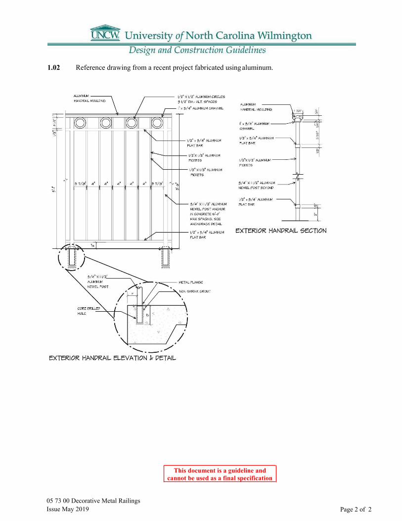
05 73 00 Decorative Metal Railings Issue May 2019
This document is a guideline and cannot be used as a final specification
Page 2 of 2
1.02 Reference drawing from a recent project fabricated using aluminum.

06 64 00 Plastic Panels Issue May 2019
This document is a guideline and cannot be used as a final specification
Page 1 of 1
06 64 00 Plastic Panels
Part 1: Applications
1.01 Kitchen Walls A. Material: Fiberglass Reinforced Plastic (FRP)B. Sheet size: 4-foot width by longest practical length to minimize seams.C. Thickness: VariesD. Finish: As specified by DesignerE. Color: As specified by DesignerF. Installation: AdhesiveG. Accessories: Manufacturer’s standard trim accessories.H. Rating: Provide fire rated products when required.
Part 2: Materials
2.01 Products A. Basis of Design Product: “Glasbord” series by Crane Composites.

06 00 00 Wood & Carpentry Issue May 2019
This document is a guideline and cannot be used as a final specification
Page 1 of 3
06 00 00 Wood and Carpentry General Requirements
Part 1: Drawings and Detailing 1.01 Rough Carpentry:
A. General: NO WOOD SHALL BE USED ON THE EXTERIOR.1. An exception to this would be sheathing as part of an insulated roof nailable base
assembly for installation of shingles. This wood is required to be fire-treated andpressure treated.
2. The Designer must obtain prior approval from the ACS Director for the use of wood inother exterior locations.
B. Indicate on drawings the following information related to Rough Carpentry.1. Extent, size, and spacing of rough carpentry, such as grounds, stripping, blocking
and equipment base “skids”. Use nominal sizes for dimension lumber, actual sizesfor engineered (worked) wood elements.
2. Actual thickness for panel products, including construction panels, particleboard,hardboard underlayment, gypsum sheathing, fiberboard sheathing, and other panelproducts.
3. Details of typical and special conditions; clearly differentiate between “carpentry”(roughand finish) and “architectural woodwork”.
4. The extent of preservative-pressure-treated and fire-retardant-treated wood.
1.02 Exterior Architectural Woodwork:
A. General: NO EXTERIOR WOODWORK PERMITTED.1. Trim and Ornamentation shall be Exterior GFRC. (see 09 29 50 Polymer Modified
GFRC)B. Indicate on drawings the following information related to Exterior GFRC:
1. The extent of each assembly of GFRC.2. Clearly distinguish responsibility of backup provider and other supporting construction
specified elsewhere.3. Dimensions for principal elements of exterior woodwork, and profiles of jambs, trim,
siding and molding (including special joinery).
1.03 Custom Built-In and Furniture: A. Custom Built-in vs. Freestanding and/or Readymade Furniture:
1. Ready-made furniture is preferred.2. The use of freestanding furniture is preferred. This choice provides easy and low-cost space
allocation changes and relocations.3. Custom and built-in furniture should be avoided where possible.

06 00 00 Wood & Carpentry Issue May 2019
This document is a guideline and cannot be used as a final specification
Page 2 of 3
1.04 Interior Architectural Woodwork: A. Indicate on drawings the following information related to Interior Architectural Woodwork:
1. The extent of each type of interior woodwork, clearly distinguished fromcarpentry and other wood construction specified elsewhere.
2. Dimensions for principal elements of the work and profiles of jambs, trimand moldings (including special joinery).
3. Location of quality grades, if more than one specified for each category and finish, and thelocation of each cannot be adequately specified.
4. Special veneer matching areas where too difficult to be specified in specification.5. Wood grain direction and plastic laminate pattern direction (where not obvious from
the specification or detailing).6. Where fire-retardant treated woodwork is required to be installed.7. Hardware Applications (coordinated with specification and/or scheduling method
used) for cabinet hardware, as distinguished from door hardware.8. Arrangement of door hardware locks, light fixtures, panel hangers, concrete
inserts (anchorage), and similar hardware and accessories not fully covered byspecification.
9. Glass doors, shelves and other similar non-wood elements of the work of this section.Part 2: Architectural Woodwork Standards and Characteristics 2.01 Applicability:
A. With the exception of hardware and glass, construction included in this section is specified to complywith Architectural Woodwork Institute (AWI) standards.
B. Grade of Woodwork: Woodworking standards have been developed on the basisof designated quality by three separate grades – Premium, Custom, and Economy.1. Premium requires the highest grade of materials and workmanship currently
recognized. It is intended for the finest work and is the most expensive grade. Premium grademight be specified for woodwork throughout an entire building, but it should not be specifiedindiscriminately. Premium should usually be specified only for selected areas or selected items thathave particular architectural significance.
2. Custom is the middle or normal grade in both material and workmanship requirements and isintended for medium-quality regular work.
3. The economy is the lowest acceptable grade in both material and workmanship requirements and isintended for work where price outweighs qualityconsiderations.
a. UNCW does not recommend the use of Economy grade woodwork for the campus.C. Substantial cost differences exist between the different grades, finishes and, for casework, different
types of cabinet construction. Transparent finished woodwork is also generally much more expensivethan woodwork with an opaque finish, depending not only the species and cut of wood selected butalso on the kind of finish required.
D. Determination of quality grade should be based on a careful study of design role, function, locationand finish of each woodwork item. If more than one grade is specified on the same job, drawings orspecifications must indicate locations and extent of each grade.

06 00 00 Wood & Carpentry Issue May 2019
This document is a guideline and cannot be used as a final specification
Page 3 of 3
2.02 Fire Retardant Treatment: A. Usually, small amounts of architectural woodwork are permitted for most occupancies and
spaces without requiring fire-retardant treatment. However, for many applications wherewoodwork (of any type) is extensive, such treatment of all or part may be required oradvisable. However, use of fire-retardant wood limits choices available with respect tomaterial and thickness and well as to treatment and finishes, particularly transparent finishes.
2.03 Cabinet Hardware: A. Because of the quality of work involved in this section, it is generally advisable to specify
that the cabinet hardware is furnished and installed by the cabinet fabricator so that a singleresponsibility is achieved. This minimizes problems with coordination and delivery as wellas the possibility of potential damage to the finish materials if hardware is supplied andinstalled in the field by others. Pivot hinges, however, should be supplied and installed inthe field because of their tendency to shift during setting and fitting of cabinets.
2.04 Chair Rails: A. Chair rails shall be considered in the design of rooms which are to contain
moveable furniture. Chair rails should be a material that does not requirefrequent painting.
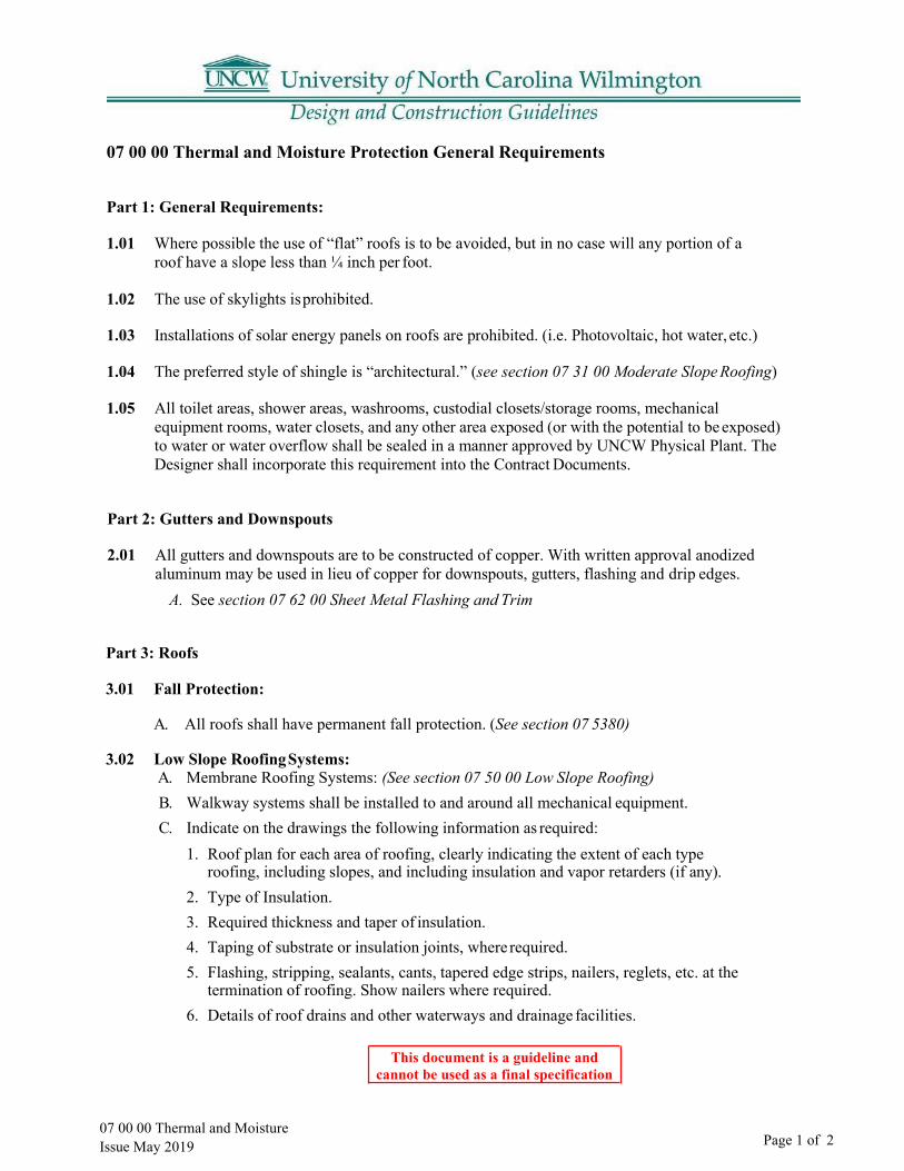
07 00 00 Thermal and Moisture Issue May 2019
This document is a guideline and cannot be used as a final specification
Page 1 of 2
07 00 00 Thermal and Moisture Protection General Requirements
Part 1: General Requirements:
1.01 Where possible the use of “flat” roofs is to be avoided, but in no case will any portion of a roof have a slope less than ¼ inch per foot.
1.02 The use of skylights is prohibited.
1.03 Installations of solar energy panels on roofs are prohibited. (i.e. Photovoltaic, hot water, etc.)
1.04 The preferred style of shingle is “architectural.” (see section 07 31 00 Moderate Slope Roofing)
1.05 All toilet areas, shower areas, washrooms, custodial closets/storage rooms, mechanical equipment rooms, water closets, and any other area exposed (or with the potential to be exposed) to water or water overflow shall be sealed in a manner approved by UNCW Physical Plant. The Designer shall incorporate this requirement into the Contract Documents.
Part 2: Gutters and Downspouts
2.01 All gutters and downspouts are to be constructed of copper. With written approval anodizedaluminum may be used in lieu of copper for downspouts, gutters, flashing and drip edges.
A. See section 07 62 00 Sheet Metal Flashing and Trim
Part 3: Roofs
3.01 Fall Protection:
A. All roofs shall have permanent fall protection. (See section 07 5380)
3.02 Low Slope Roofing Systems: A. Membrane Roofing Systems: (See section 07 50 00 Low Slope Roofing)B. Walkway systems shall be installed to and around all mechanical equipment.C. Indicate on the drawings the following information as required:
1. Roof plan for each area of roofing, clearly indicating the extent of each typeroofing, including slopes, and including insulation and vapor retarders (if any).
2. Type of Insulation.3. Required thickness and taper of insulation.4. Taping of substrate or insulation joints, where required.5. Flashing, stripping, sealants, cants, tapered edge strips, nailers, reglets, etc. at the
termination of roofing. Show nailers where required.6. Details of roof drains and other waterways and drainage facilities.

07 00 00 Thermal and Moisture Issue May 2019
This document is a guideline and cannot be used as a final specification
Page 2 of 2
7. Locations and dimensions of walkways (if any), and how they are supportedagainst slippage if the slope is more than 2 inches per ft.
8. Color of surfacing, if other than color specified.9. Areas of special UL rating, if any (other than rating specified).10. Locations and large-scale details for sheet metal roofing accessories, and type metal if
several specified.11. Locations and large-scale details of roof expansion joints, curbs, penetrations, equipment
supports, etc. (Use NCRA details as a guide).
3.03 Moderate Roofing Systems: A. Shingles: (See section 07 31 00 Moderate Slope Roofing)B. Indicate on the drawings the following information as required:
1. Roof plan for each area of roofing, clearly indicating the extent of each typeroofing, including slopes, and including insulation and vapor retarders (if any).
2. Type and thickness of insulation.3. Taping of substrate or insulation joints, where required.4. Flashing, stripping, sealants, reglets, etc. at the termination of roofing.5. Details of roof drains and other waterways and drainage facilities.6. Color of surfacing, if other than color specified.7. Areas of special UL rating, if any (other than rating specified).8. Locations and large-scale details for sheet metal roofing accessories, and type metal
if several specified, roof expansion joints, curbs, penetrations, equipment supports,etc.

07 31 00 Moderate Slope Roofing Issue May 2019
This document is a guideline and cannot be used as a final specification
Page 1 of 1
07 31 00 Moderate Slope Roofing
Part 1: General
1.01 The UNCW Standard is asphalt shingle roofing for moderate slope roofs.
Part 2: Materials
2.01 The basis of Design Product: “Timberline Ultra” by GAF Materials Corporation.
2.02 .040 peel and stick membrane are required at ridge, valley and eave conditions.
2.03 Provide minimum 30# felt underlayment.
2.04 The installer shall provide a minimum six nail per shingle or as recommended by the manufacturer for high wind conditions.
2.05 All asphalt shingle installations shall be ventilated.
2.06 Ridge vents shall be rated against water infiltration to wind speeds of 130 mph.
Part 3: Warranty
3.01 Manufacturer’s warranty: 30-years prorated, 20-years non-prorated. A. Also 15-year wind damage and 10-year algae-discoloration warranties.
3.02 Installer’s 10-year workmanship warranty is required.

07 50 00 Low Slope Roofing Issue May 2019
This document is a guideline and cannot be used as a final specification
Page 1 of 1
07 50 00 Low Slope Roofing
Part 1: General
1.01 Low Sloped Roofing is not permitted on the campus of UNCW without the written approval of the assigned UNCW project manager.
Part 2: Materials
2.01 Low slope roofing shall be .060 non-reinforced EPDM with a white face color.
2.02 A ¼” glass matt recovery board is required.
2.03 Insulation board shall be a polyisocyanurate with a minimum aged insulating R-value as established by the prescriptive requirements of the North Carolina Building Code. Insulation board shall be mechanically fastened.
2.04 Membrane shall be fully adhered.
2.05 Roofing shall meet a minimum roof slope of ¼” per foot.
2.06 Non-organic walk pads are required if the equipment is placed on the roof.
2.07 Roofing shall be specified to meet or exceed the current version of ASCE-7.
Part 3: Shop drawing requirements must include.
3.01 Sealed engineering documents demonstrating compliance with ASCE-7
3.02 Fastening schedule with cut sheets of fasteners.
3.03 Roof slopes, depth of insulation and roof drain locations.
Part 4: Warranty
4.01 Manufacturer’s twenty-year warranty is required.
4.02 Installer’s two-year warranty is required.

07 53 80 Fall Protection Issue May 2019
This document is a guideline and cannot be used as a final specification
Page 1 of 1
07 53 80 Fall Protection
Part 1: General
1.01 Permanent fall prevention/protection measures must be included as an integral part of the design phase for all new construction projects and roof renovation/repair projects at UNCW. All walking/working surfaces where employees are exposed to fall hazards (i.e. roof systems and floor openings) shall be permanently guarded or have qualified anchorages for personal fall arrest systems. Buildings that utilize powered platforms for exterior maintenance shall be provided with qualified anchorages and tie-in guides as necessary.
1.02 A qualified person with extensive experience in fall protection is required to plan, evaluate, design, and select the most appropriate fall prevention/protection solution. Building anchorages, tie-downs, and any other affected parts of the building shall be designed and certified by a registered Professional Engineer (PE) currently registered in North Carolina with expertise in fall protection systems.
1.03 A complete understanding of the work procedures will enable the design team and/or qualified person to select the most appropriate fall protection system. The schematic design phase shall include consultation with affected campus maintenance personnel that are exposed to fall hazards. The purpose of this meeting will help identify specific building maintenance and/or equipment service activities required to be conducted throughout the life of the building. In addition, the design team can discuss maintenance and inspection requirements of the proposed personal fall arrest systems and identify areas of concern.
Part 2: Materials
2.01 Basis of Design: Specified components are manufactured by Guardian Fall Protection Inc., 26513
79th Ave. S, Kent WA 98032, and are specified as the established standard of quality.
Part 3: Quality Assurance
3.01 Qualifications of the Manufacturer: Fall protection components used in the work of this section shall be produced by manufacturers regularly engaged in the manufacture and design of similar items and with a minimum of ten (10) years documented experience of successful design and production acceptable to the Owner.
Part 4: Warranty
4.01 Qualifications of the Installer: The fall protection system installer shall have a minimum of five (5) years documented experience in the installation of rooftop fall protection systems and aminimum of five (5) documented projects of similar type.

This document is a guideline and cannot be used as a final specification
07 62 00 Sheet Metal Flashing and Trim
Part 1: General
1.01 Exposed to View roof edge and roof drainage components: Gutters, Downspouts, Scuppers, Metal counter flashings, Splash pans shall be copper. With written approval anodized aluminum may be used in lieu of copper for downspouts, gutters, flashing and drip edges. A. 16 oz. Copper Sheet ASTM B 370, cold-rolled copper sheet, H00 or H01 temper.B. Fabricate in minimum 96-inch- long sections.
1.02 Downspouts to be fabricated with rectangular downspouts complete with mitered elbows.
07 62 00 Sheet Metal Flashing & Trim Issue May 2019 Page 1 of 1

This document is a guideline and cannot be used as a final
specification
07 92 00 Joint Sealants
Part 1: Applications
1.01 Brick Veneer Expansion Joints A. Basis-of-Design Product: Tremco Dymeric 240FCB. Color:
1. Basis-of-Design: Tremco “Baptist Brick”C. Location of expansion joints:
1. If possible, locate the expansion joint behind thedownspouts.
07 92 00 Joint Sealants Issue May 2019 Page 1 of 1

08 XX XX Technical Guidelines: Door Hardware Doors & Frames
The purpose of this specification is for use by UNCW to support the UNCW standards of door hardware, hollow metal doors, and frames. UNCW maintains the following hardware and is currently stocking replacement parts. The products listed in this booklet are to be used without substitution on new construction and modernization projects.
It is the intent of this section to provide guidelines for UNCW. This Technical Guide is in alignment with the UNCW Section 08 71 00 Master Guide Specification. The Master Guide Spec 08 71 00 shall be provided to an architect for use in preparing the project hardware sets within the 08 71 00 specifications. It shall remain the architect's responsibility to coordinate the specifications to meet the applicable building codes, life safety codes, and ADA requirements. Hardware, doors, and frames must comply, where applicable with positive fire test: UL10C or other approved testing agency stating material has passed UBC standard 7-2.
The door hardware section 08 71 00 preamble must include the following:
Before hardware installation, general contractor/construction manager shall coordinate a hardware installation seminar to be conducted on the installation of hardware, specifically of locksets, closers, exit devices, and overhead stops. Manufacturer's representative of the above products shall present this seminar. Seminar shall be held at the job site and attended by installers of hardware (including low voltage hardware) for aluminum, hollow metal and wood doors. Training shall include use of installation manuals, hardware schedule, templates and physical products samples.
The lock, exit device and door closer manufacturers’ representative shall complete a post- installation review for proper adjustment and installment of exit devices and closers prior to building turnover to the school district. A report shall be submitted to the Architect for his/her review and information.
Exterior Building Entry Doors: Typically, FRP type doors. Confirm the exterior door types with UNCW Architectural Services Department.
In the event of conflict between sections 08 XX XX Technical Guidelines: Door Hardware Doors & Frames and 08 71 00 DOOR HARDWARE , section 08 XX XX Technical Guidelines: Door Hardware Doors & Frames shall take precedent and shall be considered correct.
08 xx xx Technical Guidelines for Door Hardware: Doors & Frames Issue May 2019
Page 1 of 11
This document is a guideline and cannot be used as a final specification

This document is a guideline and cannot be used as a final specification
08 xx xx Technical Guidelines for Door Hardware: Doors & Frames Issue May 2019 Page 2 of 11
08 xx xx Technical Guidelines for Door Hardware: Doors & Frames
1.01 Pre-Installation Conference: Prior to the installation of door hardware, the hardware supplier and the project contractor shall arrange and hold a job site meeting to instruct the Installers personnel on the proper installation of locks, closers, and exit devices. A letter of compliance, indicating when this meeting is held and who is in attendance, shall be sent to the Architect and Owner. See Section 087100 Master Guide Specification, 1.6 Quality Assurance, Paragraph C.
1.02 Coordination:
A. Installation Coordination Conference: Prior to hardware installation, schedule and hold ameeting for the purpose of reviewing any questions or concerns related to the properinstallation and adjustment of door hardware.
1. Attendees: doors hardware supplier, door hardware installer, Owner, Contractor.2. After the meeting, provide letter of compliance to the Architect, indicating when
the meeting was held and who was in attendance.B. Electrified Hardware Coordination Conference: Prior to project electrical rough-in,
schedule and hold a meeting for the purpose of coordinating electrified door hardwarewith security, electrical, doors and frames, and other related trades.
1. Attendees: electrified door hardware supplier, doors and frames supplier,electrified door hardware installer, an electrical subcontractor, the accesscontrol provider/Integrator, the Owner’s representative, Architect, andGeneral C
2. Contractor.3. After meeting, provide letter of compliance to the Architect, indicating when the
coordination conference was held and who was in attendance.1.03 Supplier Qualifications and Responsibilities: A recognized architectural hardware supplier
that has a record of successful in-service performance for supplying door hardware similar in quantity, type, and quality to that indicated for this Project and that provides a certified Architectural Hardware Consultant (AHC) available to the Owner, Architect, and Contractor, at reasonable times during the course of the Work for consultation.
A. Installer shall be certified by product manufacturer.B. Warehousing Facilities: In Project's vicinity.C. Scheduling Responsibility: Preparation of door hardware and keying schedules.D. Engineering Responsibility: Preparation of data for electrified door hardware, including
Shop Drawings, based on testing and engineering analysis of manufacturer's standardunits in assemblies similar to those indicated for this Project.
E. Coordination Responsibility: Coordinate installation of the electronic security hardwarewith the Architect and electrical engineers and provide installation and technical data tothe Architect and other related subcontractors.
1. Upon completion of electronic security hardware installation, inspect and verifythat all components are working properly.
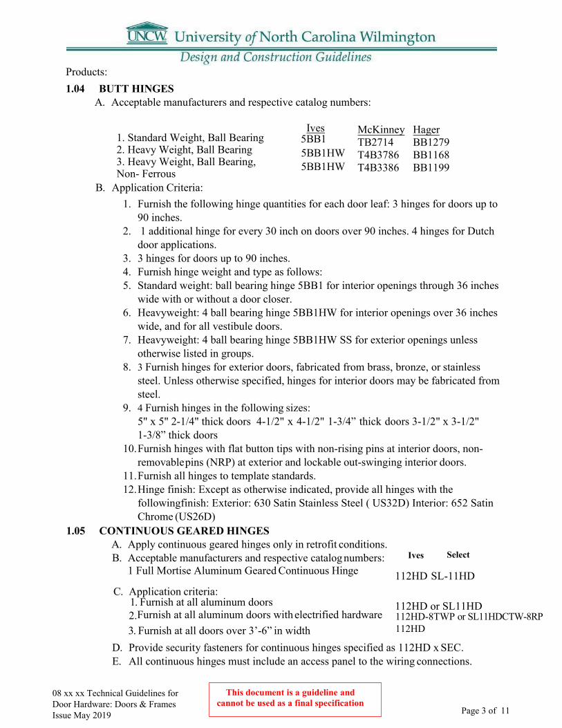
This document is a guideline and cannot be used as a final specification
08 xx xx Technical Guidelines for Door Hardware: Doors & Frames Issue May 2019 Page 3 of 11
Products: 1.04 BUTT HINGES
A. Acceptable manufacturers and respective catalog numbers:
Ives 5BB1 5BB1HW
1. Standard Weight, Ball Bearing2. Heavy Weight, Ball Bearing3. Heavy Weight, Ball Bearing,Non- Ferrous 5BB1HW
McKinney Hager TB2714 BB1279 T4B3786 BB1168 T4B3386 BB1199
B. Application Criteria:1. Furnish the following hinge quantities for each door leaf: 3 hinges for doors up to
90 inches.2. 1 additional hinge for every 30 inch on doors over 90 inches. 4 hinges for Dutch
door applications.3. 3 hinges for doors up to 90 inches.4. Furnish hinge weight and type as follows:5. Standard weight: ball bearing hinge 5BB1 for interior openings through 36 inches
wide with or without a door closer.6. Heavyweight: 4 ball bearing hinge 5BB1HW for interior openings over 36 inches
wide, and for all vestibule doors.7. Heavyweight: 4 ball bearing hinge 5BB1HW SS for exterior openings unless
otherwise listed in groups.8. 3 Furnish hinges for exterior doors, fabricated from brass, bronze, or stainless
steel. Unless otherwise specified, hinges for interior doors may be fabricated fromsteel.
9. 4 Furnish hinges in the following sizes:5" x 5" 2-1/4" thick doors 4-1/2" x 4-1/2" 1-3/4” thick doors 3-1/2" x 3-1/2"1-3/8” thick doors
10.Furnish hinges with flat button tips with non-rising pins at interior doors, non- removable pins (NRP) at exterior and lockable out-swinging interior doors.
11.Furnish all hinges to template standards.12.Hinge finish: Except as otherwise indicated, provide all hinges with the
followingfinish: Exterior: 630 Satin Stainless Steel ( US32D) Interior: 652 SatinChrome (US26D)
1.05 CONTINUOUS GEARED HINGES
112HD SL-11HD
112HD or SL11HD
A. Apply continuous geared hinges only in retrofit conditions.B. Acceptable manufacturers and respective catalog numbers:
1 Full Mortise Aluminum Geared Continuous Hinge
C. Application criteria:1. Furnish at all aluminum doors2. Furnish at all aluminum doors with electrified hardware3. Furnish at all doors over 3’-6” in width
112HD-8TWP or SL11HDCTW-8RP 112HD
D. Provide security fasteners for continuous hinges specified as 112HD x SEC.E. All continuous hinges must include an access panel to the wiring connections.
Ives Select

This document is a guideline and cannot be used as a final specification
08 xx xx Technical Guidelines for Door Hardware: Doors & Frames Issue May 2019 Page 4 of 11
1.06 POWER TRANSFERS A. Preferred manufacturers and respective catalog numbers:
Von Duprin EPT-2 1. Concealed Two Wire
2. Concealed Ten Wire EPT-10 B. Concealed power transfers shall be concealed in the door and frame when the door is closed.C. Concealed power transfers shall have a steel tube to protect wires from being cut.D. Concealed power transfers with spring tubes shall be rejected.E. Concealed power transfers shall be supplied with a mortar guard to house all terminations.
1.07 FLUSH BOLTS AND DUST PROOF STRIKES A. Typical products respective catalog numbers:
Ives Rockwood Trimco
571 DP2 1842 3810 1942 3815
555 3915
1. Dust Proof Strike DP2 2. Auto Flush Bolt (Metal Door) FB31P3. Auto Flush Bolt (Wood Door) FB41P4. Manual Flush Bolt FB458
A. Acceptable preferred manufacturer and respective catalog numbers:Von Duprin
1. Wide Stile, Push Pad 99 SeriesB. Application criteria (if alternate manufacturer is used, supplied device must equalthose listed below in function and grade):
1. Rim Panic 99/98 Series 2. Exterior aluminum entrances (Single) 99/98 Series3. Exterior aluminum entrances (Pair) KR4954 Mullion x 9/994. Concealed Vertical Cable Device (hollow metal or aluminum drsonly)9849(secure)5. Concealed Vertical Cable Device (hollow metal or aluminum drsonly)9849 LBR (non-secure
area)6. Concealed Vertical Cable Device (wood doors only) 9850WDC7. Exterior Trim 990 Series8. Latch retraction (only approved by Physical Security) EL ( 16 amp in-rush)
a. Quiet latch retraction – Preferred application QELb. Power transfer (required on exterior doors with electrified devices or locks) EPTc. Power Supply (Electric latch retraction devices) PS914 x 900-4RLd. Power Supply (Delayed egress devices) PS914
C. Applications:1. Pairs of exterior doors: Two (2) rim exit devices with removable mullion.2. Pairs of cross-corridor doors: Two (2) concealed vertical cable exit devices less bottom rod
(LBR).3. Single exterior doors: One (1) rim exit device (no lever trim).4. Single interior doors: One (1) rim exit device.
1.08 EXIT DEVICES

This document is a guideline and cannot be used as a final specification
08 xx xx Technical Guidelines for Door Hardware: Doors & Frames Issue May 2019 Page 5 of 11
1.10 KEYING A. General: Provide ten (10) temporary keyed construction cores for the contractor’s use
during the construction period of the project. Furnish keyed construction cores at allexterior doors, including the cylinder dogging at exit devices. Balance oflocks/cylinders may be furnished with factory produced plastic plugs. Constructioncontrol and operating keys and cores shall not be part of the Owner’s permanentkeying system or furnished on the same keyway as the Owner’s permanent keyingsystem. Permanent cores and keys shall be keyed to the approved keying schedule.All cylinders shall be Everest 7-pin, interchangeable core and keyed to existingpatented Factory- Registered Grand Masterkey System.
B. Permanent keys and cores shall be stamped with applicable key mark foridentification. These visual key control codes shall not include the actual key cuts.Permanent keys/key blanks will also be stamped “Do Not Duplicate.”
C. The Owner’s existing key system: “Schlage”, with the specific keyway to bedetermined by the Owner, and with the Schlage Key representative.
D. Furnish keys in the following quantities:1. each Master keys per set2. each Change Keys per keyed core or keyed group. Do not cut keys for any
exterior door cylinders where the UNCW card reader function is specified.3. each Construction Master keys4. each key blanks per core
E. At project completion, the UNCW Locksmith Shop shall install the permanentkeyed cores. All construction cores and keys shall be returned to the UniversityConstruction Project Manager for return the hardware supplier. All permanentkeyed cores, keys, and key blanks shall be delivered directly to the Owner from thehardware supplier via Registered Delivery, Return Receipt Required.
F. Keys shall be sent via Registered Mail to:
1.11 PULLS, PUSHBARS, PUSH/PULL PLATES
A. Typical trim applications as referenced with Ives catalog numbers:Ives Other Accepted Trimco & Rockwood Straight Pull (1" dia., 10" ctc) (Interior) 8103EZ-0 Offset Pull: 12”/ 18” 8190 Pull / Push-Bar (1" dia., 10" ctc Pull) (Interior) 9103EZ-0 Push Plate (.050 4"X 16") 8200 4 x 16
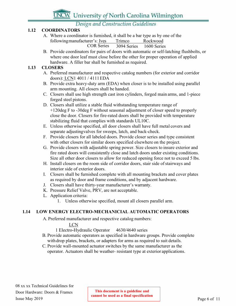
This document is a guideline and cannot be used as a final specification
08 xx xx Technical Guidelines for Door Hardware: Doors & Frames Issue May 2019 Page 6 of 11
1.12 COORDINATORS A. Where a coordinator is furnished, it shall be a bar type as by one of the
following manufacturer’s: Ives Trimco RockwoodCOR Series 3094 Series 1600 Series
B. Provide coordinators for pairs of doors with automatic or self-latching flushbolts, orwhere one door leaf must close before the other for proper operation of appliedhardware. A filler bar shall be furnished as required.
1.13 CLOSERS A. Preferred manufacturer and respective catalog numbers (for exterior and corridor
doors): LCN1 4011 / 4111 EDAB. Provide extra heavy-duty arm (EDA) when closer is to be installed using parallel
arm mounting. All closers shall be handed.C. Closers shall use high strength cast iron cylinders, forged main arms, and 1-piece
forged steel pistons.D. Closers shall utilize a stable fluid withstanding temperature range of
+120deg F to -30deg F without seasonal adjustment of closer speed to properlyclose the door. Closers for fire-rated doors shall be provided with temperaturestabilizing fluid that complies with standards UL10C.
E. Unless otherwise specified, all door closers shall have full metal covers andseparate adjusting valves for sweeps, latch, and back-check.
F. Provide closers for all labeled doors. Provide closer series and type consistentwith other closers for similar doors specified elsewhere on the project.
G. Provide closers with adjustable spring power. Size closers to insure exterior andfire rated doors will consistently close and latch doors under existing conditions.Size all other door closers to allow for reduced opening force not to exceed 5 lbs.
H. Install closers on the room side of corridor doors, stair side of stairways andinterior side of exterior doors.
I. Closers shall be furnished complete with all mounting brackets and cover platesas required by door and frame conditions, and by adjacent hardware.
J. Closers shall have thirty-year manufacturer’s warranty.K. Pressure Relief Valve, PRV, are not acceptable.L. Application criteria:
1. Unless otherwise specified, mount all closers parallel arm.
1.14 LOW ENERGY ELECTRO-MECHANICIAL AUTOMATIC OPERATORS A. Preferred manufacturer and respective catalog numbers:
LCN 1 Electro-Hydraulic Operator 4630/4640 series
B. Provide automatic operators as specified in hardware groups. Provide completewith drop plates, brackets, or adapters for arms as required to suit details.
C. Provide wall-mounted actuator switches by the same manufacturer as theoperator. Actuators shall be weather- resistant type at exterior applications.

This document is a guideline and cannot be used as a final specification
08 xx xx Technical Guidelines for Door Hardware: Doors & Frames Issue May 2019 Page 7 of 11
D. Provisions in the control box shall provide control (inputs and outputs) for: electric strikedelay, auxiliary contacts, sequential operation, fire alarm systems, actuators, sensors.
E. The operator shall provide a power shut-off switch to the operator control box.
1.15 KICK PLATES AND MOP PLATES A. Furnish protective plates as specified in hardware groups.B. Where specified, provide 8" kick plates, 36" armor plates, and 4" mop plates. Unless
otherwise specified, metal protective plates shall be .050" thick.C. Protective plates shall be 2" less door width, or 1" less door width at pairs. All protective
plates shall be beveled 4 sides and have counter sunk screw holes. Protection plates over16" shall not be provided for labeled doors unless specifically approved by doormanufacturers listing.
D. Where required byadjacent hardware, protection plates shall be factory drilled for cylindersor other mortised hardware.
E. Application: Provide armor plates for loading dock doors, cafeteria doors, exteriormechanical rooms, riser and pump rooms, field house and press box doors, and concessionstands.
F. Acceptable Manufacturers: Ives/ Rockwood/Trimco1.16 WALL STOPS AND HOLDERS
A. Acceptable types of stops:Wrought Convex Wall Bumper Wrought Concave Wall Bumper Extended Wall Stop Extended Wall Stop Automatic Wall Holder Overhead Heavy-Duty Surface- mount Stop/Holder at interior doors where required
B. Furnish a stop for all doors.C. Where wall stops are not applicable, furnish floor stops.D. Do not provide holder function for labeled doors.E. Where an overhead stop is required, a surface type is preferred such as Glynn
Johnson 90Sseries.F. Acceptable Manufacturers: Ives/Rockwood/Trimco for wall / floor
stops.Overhead stops: GJ/Rixson/ABH
1.17 WEATHERSTRIP, GASKETING
A. Acceptable manufacturers and respective catalog numbers:
Zero 188s NGP 5050 Reese 797
B. Provide drip cap for all exterior HM frames, unless positioned under a canopy.

This document is a guideline and cannot be used as a final specification
08 xx xx Technical Guidelines for Door Hardware: Doors & Frames Issue May 2019
Page 8 of 11
1.18 THRESHOLDS A. Acceptable manufacturers and respective catalog numbers:
Zero NGP Reese 655 425 S205 65A 896A S486A
1. Saddle Thresholds2. Panic Type Thresholds3. Interlocking Threshold 74A 442-5 T550
B. Hardware supplier shall verify all finish floor conditions and coordinate properthreshold as required to insure a smooth transition between threshold andinterior floor finish.
C. Threshold Types:
1. Unless otherwise specified, provide saddle threshold similar to Zero 655A forall exterior openings with an interior floor finish less than or equal to 1/4" inheight.
2. Unless otherwise specified, provide half saddle threshold similar to Zero 1674for all exterior openings with an interior floor finish greater than 1/4" inheight. Threshold height shall match thickness of interior floor finish.
1.19 DOOR POSITION SWITCHES- See UNCW Physical Security for application & coordination
A. Acceptable manufacturers and respective catalog numbers:
GE Schlage Electronic
1 Concealed 1078C 679 series
1.20 ELECTRIFIED HARDWARE FUNCTIONS
B. General: operation of the card reader access control system shall be managed bythe UNCW Physical & Access Department. Card readers, credentials, monitoring,alarms shall be furnished under Division 28. Refer to the current UNCW PhysicalSecurity & Access Standards.
C. The door function shall be as specified in the Finish Hardware Sets. Openingsshall be furnished with all materials listed to provide the security function andcontrol required by the Owner. All hardware sets with electrified hardware shallinclude an operational description. A riser wiring diagram shall be required aspart of the HW Set for electrified functions.
D. Typical electrified hardware applications:
1. Entry Door with card reader and handicap operator. The following productsshall be specified:
a. Electrified exit device: QEL-RX-LC 98-NL/NL-OP. Power supply asPS914-4RL. Electric hinge as Continuous: EPT or TW8 x Rem Panel. AsButt Hinge: TW-8. Auto- operator with actuators. Door position switch.Card reader by Div. 28.
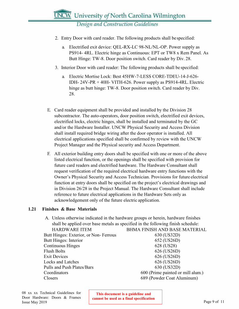
This document is a guideline and cannot be used as a final specification
Page 9 of 11
08 xx xx Technical Guidelines for Door Hardware: Doors & Frames Issue May 2019
2. Entry Door with card reader. The following products shall be specified:
a. Electrified exit device: QEL-RX-LC 98-NL/NL-OP. Power supply asPS914- 4RL. Electric hinge as Continuous: EPT or TW8 x Rem Panel. AsButt Hinge: TW-8. Door position switch. Card reader by Div. 28.
3. Interior Door with card reader: The following products shall be specified:
a. Electric Mortise Lock: Best 45HW-7-LESS CORE-TDEU-14-J-626-IDH- 24V-PR + 40H- VITH-626. Power supply as PS914-4RL. Electrichinge as butt hinge: TW-8. Door position switch. Card reader by Div.28.
E. Card reader equipment shall be provided and installed by the Division 28subcontractor. The auto-operators, door position switch, electrified exit devices,electrified locks, electric hinges, shall be installed and terminated by the GCand/or the Hardware Installer. UNCW Physical Security and Access Divisionshall install required bridge wiring after the door operator is installed. Allelectrical applications specified shall be confirmed by review with the UNCWProject Manager and the Physical security and Access Department.
F. All exterior building entry doors shall be specified with one or more of the abovelisted electrical function, or the openings shall be specified with provision forfuture card readers and electrified hardware. The Hardware Consultant shallrequest verification of the required electrical hardware entry functions with theOwner’s Physical Security and Access Technician. Provisions for future electricalfunction at entry doors shall be specified on the project’s electrical drawings andin Division 26/28 in the Project Manual. The Hardware Consultant shall includereference to future electrical applications in the Hardware Sets only asacknowledgement only of the future electric application.
1.21 Finishes & Base Materials
A. Unless otherwise indicated in the hardware groups or herein, hardware finishesshall be applied over base metals as specified in the following finish schedule:HARDWARE ITEM BHMA FINISH AND BASE MATERIAL
Butt Hinges: Exterior, or Non- Ferrous 630 (US32D) Butt Hinges: Interior 652 (US26D) Continuous Hinges 628 (US28) Flush Bolts 626 (US26D) Exit Devices 626 (US26D) Locks and Latches 626 (US26D) Pulls and Push Plates/Bars 630 (US32D) Coordinators 600 (Prime painted or mill alum.) Closers 689 (Powder Coat Aluminum)

This document is a guideline and cannot be used as a final specification
Page 10 of 11
08 xx xx Technical Guidelines for Door Hardware: Doors & Frames Issue May 2019
Protective Plates 630 (US32D) Wall Stops and Holders 630 (US32D) Thresholds 628 (Mill Aluminum) Weather-strip, Sweeps Drip Caps Aluminum Anodized Magnetic Holders Sprayed Aluminum Magnetic Locks 628 (US28) Miscellaneous 626 (US26D)
1.22 Miscellaneous A. Furnish 3-5 extra Schlage Everest keyed cores as attic stock for each project.
Part 2: General:
UNCW has proprietary specifications that the Designer must utilize. See attached hardware specification section for additional information.
UNCW Physical Plant, through its in-house lock shop, is required to maintain, repair, and interchange many locks, cylinders, exit devices, and assorted other items of Finish Hardware on an ongoing basis. In order to maximize the value and economics of a standardized hardware system, it is necessary that proprietary specifications be instituted for many of the hardware items; thus, the specific items listed herein are to be considered mandatory/proprietary. In addition, the Designer shall coordinate the finish hardware schedule with the UNCW Physical Plant Lockshop.
Part 3: Design:
3.01 Access Control: A. Locking and Security shall be designed in coordination with the Owner. The system shall
accommodate the varying hours of operation and the requirements for restricted access todesignated areas.
B. See Section 28 13 00 Access Control Equipment for additional information andrequirements.
Part 4: Drawings:
4.01 Indicate on drawings the following information related to Finish Hardware: A. Designation of each door opening on floor plan and coordination with specific data on
door and frame schedule.B. Notation of hardware sets for each door opening, either indoor and frame schedule, or
on floor plans when hardware schedule does not include a listing of the opening wheresets occur.
C. Hand of door swing (size, weight, exposure, special clearances, etc.).D. Special sill, head, joints, or meeting stile conditions affecting type, size, installation or
clearance, etc. of hardware units.E. Location and notation of UL label and fire resistance rating requirements.
2.01
2.02
This document is a guideline and cannot be used as a final specification
Page 11 of 11
08 xx xx Technical Guidelines for Door Hardware: Doors & Frames Issue May 2019
F. For pairs of doors, indicate which leaf is active, where this is critical to properoperation.
G. Special hardware installation requirements, if any, including unusual security,through- bolting, unusual concealed fasteners, etc.
H. Mounting locations, if different than specified.I. Style and location of bumpers and similar devices, wherever their appearance is considered
crucial.
Part 5: Shop Drawings
Cut Sheets and other data describing all hardware items which the contractor proposed to shall be provided during construction with the hardware shop drawing proposal. These shall be furnished, be reviewed, and approved by the UNCW Locksmith Supervisor.
A. Prior to ordering, all Shop Drawings, cut sheets, etc. shall be reviewed and approved byUNCW Locksmith Supervisor (Physical Plant).
The Sample Door Hardware Specification is to be used as a guide and is for reference only. The designer should review the document to identify University preferred manufacturers and installation practices that will be required to be incorporated into the new project. The Designer will meet with the University during the appropriate design phase to start planning and coordinating access control.
5.01
Part 6: Door Hardware Specification Sample 6.01
6.02
Page 1 of 2
08 00 00 Doors - General Guidelines
Part 1: General
1.01
1.02 All doors shall be solid core. Where appropriate doors shall be provided with view panels
1.03 All exterior doors shall be FRP 6 panel with continuous hinges.
A. Aluminum may also be used.B. Hollow metal doors may be used for exterior utility room doors where not in direct view
to the public areas.
1.04 All hallway and stairwell doors shall have vision panels and continuous hinges. 1.05 Knock-Down frames are not permitted except where specifically noted or where absolutely
required in renovation work.
Part 2: Drawings
2.01 All doors. Indicate on drawings the following information:
A. Location of each door and frame unit.B. Direction of door swing (hand).C. Size and type of units, by elevation. Indicate if door thickness other than 1 3/4 inches.
Show openings in doors. Indicate side lights and transoms and dimensions.D. Details to establish jamb depth, rabbets, stop size, reveal depth, trim, louver types, etc.E. Sections through head, jamb, mullion, and transoms for each type of wall condition.F. Thermally insulated assemblies.G. Fire-rated assemblies with hour rating and classification (A, B, C). Provide maximum
temperature rise, if required.H. Sound-rated assemblies.I. Applied hardware items.J. Prefinished doors and frames. Coordinate color selections with sample submittal
requirements.K. Number for each opening and include a door schedule (on the drawings) that may include
some of the items above.L. Include interior and exterior gates in Door schedule.
This document is a guideline and cannot be used as a final specification
08 00 00 Doors - General Guidelines Issue May 2019
lights, especially in high traffic areas.
Keying Conference: A Keying Conference shall be conducted five to six months prior to completion of each Building Project. As a minimum the General Contractor, UNCW Construction Services Project Manager, Department Heads, UNCW Locksmith and Keying Representative (Schlage) shall be present. See 08 71 00 paragraph 1.6 for additional details.

Page 2 of 2
2.01 Metal Doors. Indicate on drawings the following additional information:
A. Special finishes. Indicate grain direction for No. 4 stainless- steel finish.
B. Basis of Design Product: Metal Doors and Frames, Steelcraft, Ceco, or Curries.
2.02 Wood & FRP Doors. Indicate on drawings the following additional information:
A. Transom and side panels in the same frame as wood doors, if specified are to match doors inconstruction and appearance; include details of attachment to frame and configuration ofbottom edge of transom panels.
B. Cutouts for Openings: Show sizes and trim. Do not exceed manufacturers limitations relativeto minimum widths of stiles and rails and separation distance between cutouts for louvers,lights and hardware.
C. Louvers: Show size and details of louvers.
D. Extra Stile and Rail Widths: Indicate widths and locations of doors requiring special stile andrail widths to accommodate hardware.
E. Where a variety of veneers, finishes, and paint or plastic, laminate colors are required for eachtype of door construction, indicate location of each on schedules or drawings.
F. Wood-Veneer-Faced Doors: Indicate finish as “transparent” or “opaque” for each door unlessonly one or the other is exclusively specified.
G. Basis of Design Product: Wood Doors, “Signature Series”, Marshfield Doors.
This document is a guideline and cannot be used as a final specification
08 00 00 Doors - General Guidelines Issue May 2019

Page 1 of 3
08 11 13 Hollow Metal Doors and Frames
Part 1: Shop Drawings must include: 1.01
1.02 Coordination of glazing frames and stops.
1.03 Schedule must use same reference numbers for details and openings as those on Drawings.
1.04 Coordination of locations of conduit and wiring boxes for electrical connections on plans and schedules.
1.05 Manufacturers shall provide documentation for UL10C or other approved testing agency stating that hollow metal applications have passed UBC 7-2. All necessary instructions and documentation shall be supplied to job site as required for code officials' approval of application.
Part 2: Standard Metal Doors
2.01 Full flush (no visible seams on either face); 1-3/4” thick; 16-gauge ASTM A36 panels, tops,and bottoms; 12- gauge closer reinforcement; 6-gauge hinge reinforcement; 14-gauge lock reinforcement; procured, pre-formed rigid polystyrene core; factory-cleaned, treated, and primed.
2.02 Door Hardware Reinforcements A. Reinforce for rim exit devices with14 gauge steel channels projection
welded or bonded to the door edge at lock and hinge side of door. Reinforceat top and bottom of doors for surface mounted vertical latches.
B. Reinforcement for Mortise locks shall be 14-gauge steel projection welded to edge ofdoor with stabilizing tabs to keep lock body centered in mortise.
C. Reinforcement for cylindrical latch/locksets with 16-gauge steel projection welded toedge of door. The reinforcement to include tabs to center thelatch bolt horizontally and vertically.
D. Reinforcement for flushbolts shall be 16-gauge steel angle projection welded to edge ofdoor or 14-gauge steel astragal with tabs drilled and tapped to receive flush bolt.
E. Reinforcement for surface mounted door closers shall be 14-gauge steel channel 14”deep x 20”long.
F. Provide high frequency hinge reinforcements at top & bottom hinge of allexterior doors and in high traffic applications such as stair wells, cafeteriasand loading dock areas.
2.03 Mortised Hardware preps including function holes shall be prepared by manufacturer or supplier prior to delivery to job site using hardware manufacturers’ templates. Trim holes and mounting holes shall be field drilled and tapped.
This document is a guideline and cannot be used as a final specification08 11 13 Hollow Metal Doors and Frames
Issue May 2019
Frame type and door type elevations, door edge details,frame profiles, metal thicknesses, preparations for hardware, conditions at each opening, and other details.
Page 2 of 3
2.04 2.05 2.06 2.07
2.08
2.09
2.10
2.11
3.01 Min. 16-gauge; frame corners mitered, welded, ground smooth; factory cleaned, treated and primed.
A. Knock-Down frames are permitted only where specifically noted or where absolutelyrequired in renovation work.
For exterior doors and frames, and elsewhere specifically noted, specify ASTM A 60 hot dipped galvanized 0.6 oz. coating, per ASTM A 924, mill-treated for primer adhesion.
3.04 Fully enclosed mortar boxes over all mortise hardware preparations. Coordinate the locations of conduit and wiring with the specified electrified door hardware. Refer to Riser Diagrams on the electrical drawings.
3.05 All mortised Hardware shall be prepared by manufacturer or supplier prior to delivery using hardware manufacturers templates. Surface hardware shall be drilled and tapped in the field.
3.06 Provide a minimum of 3 anchors per standard height or 2’6” on center. Provide additional anchors per manufacturers recommendations for frames 7’6” and higher and fire rated frames
3.07 Provide all necessary sleeves or clips at frame splices and weld all field splices to match frame. Splices must be welded and ground smooth and puttied if necessary to conceal splice.
This document is a guideline and cannot be used as a final specification
08 11 13 Hollow Metal Doors and Frames Issue May 2019
A. Spreader bars – 16-gauge channel (2 min per door opening) Spreader bars shall beremoved prior to plumbing and securing frame in wall.
B. Hinge reinforcements shall be 7 gaugeC. Provide high frequency hinge reinforcements at top & bottom hinge of all exterior
frames and high traffic applications such as cafeteria,stairwells, and loading dock areas.
D. Surface mounted closer reinforcements shall be 14-gauge steel plate welded inside jamb.E. Reinforce for rim mounted strikes with 14-gauge steel sheet welded on inside of jamb.F. Drill and tap for surface mounted hardware at jobsite.G. Strikes for mortise locks and cylindrical locks shall be 4-7/8” and conform to ANSI
A115.1 and A115.2
Surface mounted hardware shall be drilled and tapped in the field. Doors shall have 1/8” in 2” bevel both hinge and strike edge of door. Reinforce top and bottom of door with 18-gauge steel channel welded to face skins. Light kits shall be one piece 24 gage formed steel with reinforced and welded corners. Kits shall be flush with face of door and have no exposed fasteners. Finish tops of exterior doors with flush top cap welded or applied with screws to secure top cap into top channel of door. All seams and exposed fasteners shall be completely sealed & watertight. Polystyrene core doors in locations as dictated by insulation value requirements for that location are acceptable. Vertical stiffened doors will not be accepted. Avoid dark color finish paints on Polystyrene core doors at exterior applications. Polystyrene core doors painted in dark colors may absorb heat from the sun and swell to causing binding in the frame. Manufacturers shall provide documentation illustrating test results of ANSI A250.4 and ANSI A250.5
Part 3: Metal Frames
3.02
3.03 Frame Reinforcements

Page 3 of 3
3.08 Frames shall have three rubber silencers per strike jamb and two per double door head applied by manufacturer.
Part 4: Fire rated Assemblies
4.01 Automatic drop seals, when used, are to be mounted into the bottom of the door.
Part 5: Warranty
5.01 Two (2) year warranty (guarantee) period on all materials, equipment and systems.
This document is a guideline and cannot be used as a final specification
08 11 13 Hollow Metal Doors and Frames Issue May 2019

This document is a guideline and cannot be used as a final specification
08 14 16 Flush Wood Doors
Part 1: General:
1.01 Exterior wood doors are not permitted. FRP doors (6 panel) are required for exterior applications. See Section 08 16 16 Acrylic Modified Polyester Doors (FRP Doors).
Part 2: Construction
2.01 Non-Rated Solid Core Doors for Transparent Finish: Provide doors that comply with requirements for WDMA “Heavy Duty” Door WDMA Symbol PC-5.
A. Faces: Plain sliced, ‘Select’ White Maple.B. Grade: Premium, Grade ‘A’ Face Veneer.C. Construction: Manufacturer’s standard 5 plies.D. Core: Particleboard core.E. Bonding: Stiles and rails bonded to the core, then entire unit abrasive planed before
veneering.F. Edges: Same species or compatible hardwood.
2.02 Fire-Rated Solid Core Doors: A. Faces and Grade: Provide faces and grade to match non-fire-rated doors in the same area of
building.B. Blocking: Provide optional composite blocking designed to maintain fire resistance of door
but with the improved screw-holding capability of the same thickness as the core. Locateblocking at all hardware points.
C. Edge Construction: Provide manufacturer’s standard laminated-edge construction forimproved screw-holding capability and split resistance as compared to edges composed ofa single layer of treated lumber.
D. Pairs: Equip fire-rated pairs receiving exit devices with edges which are labeled andlisted for kinds of applications indicated without overlapping astragals.
2.03 Veneer Matching A. Within Door Faces: Provide Book matching.B. Pairs and Sets: Provide pair matching and set matching for pairs of doors and for doors hung
in adjacent sets.C. Doors with Transoms (as occurs): Provide continuous matching.
Part 3: Warranty:
3.01 Interior location: Life of original installation; includes repairing, replacing, recharging, refinishing.
08 14 16 Flush Wood Doors Issue May 2019 Page 1 of 1

08 16 16 FRP Doors Issue May 2019
This document is a guideline and cannot be used as a final specification
Page 1 of 1
08 16 16 Acrylic Modified Polyester Doors (FRP)
Part 1: General
1.01 Basis-of-Design Product: Special-Lite, Inc. #SL-18, SL-19, and SL-22 Series. A. Design: 6 panelB. Door Thickness: 1-3/4 inchesC. Submit manufacturer’s shop drawings, including elevations, sections, and details, indicating
dimensions, tolerances, materials, fabrication, doors, panels, framing, hardware schedule, andfinish.
Part 2: Warranty
2.01 Manufacturer’s standard 10 Year Warranty.

08 51 13 Aluminum Windows Issue May 2019
This document is a guideline and cannot be used as a final specification
Page 1 of 1
08 51 13 Aluminum Windows
Part 1: General - Fixed Aluminum Windows
1.01 Basis-of-Design Product: Peerless, Inc. Model, G600series models, Offset Fixed Window custom panning. including:
A. Frame Depth: 4 inches. Thermally broken.B. Muntins: Triple grid (interior, interstitial, exterior muntins).C. Color: Custom White matching UNCW Standard.D. Finish: High-performance organic coatingE. Glazing: Double, clear, transparent.
Part 2: Performance Requirements:
2.01 Design and size windows to withstand wind load requirements at 1.5 times the design wind loads with 10-second duration of maximum load: A. Design Wind Loads: Comply with requirements of ASCE 7, Section 6.5, Method 2
Analytical Procedure based on mean roof heights above grade indicated on the Drawings.B. Verify requirements with latest building codes.
2.02 Windborne Debris Resistance: Comply with current code requirements.
2.03 Movement: Accommodate movement between window and perimeter framing and deflection of lintel, without damage to components or deterioration of seals.
Part 3: Warranty
3.01 10 Year manufacturer warranty against failure of glass seal on insulating glass units. Include provision for replacement of failed units.
3.02 5 Year manufacturer warranty against excessive degradation of exterior finish. Include provision for replacement of units with excessive fading, chalking, or flaking.

08 71 00 Door Hardware Part 1 General Description of Work 1.01 A. Work under this section comprises the furnishing and installation of finish and
security hardware specified herein and noted on drawings for a complete and operational system, including any electrified door hardware components including finish and security hardware and auto operators for aluminum entrance doors, FRP doors, and wood doors.
B. Items include but are not limited to the following:1. Hinges: Butt-type and Continuous2. Flush Bolts: Manual and Automatic Exit Devices3. Locksets and Cylinders4. Push Plates and Pulls5. Coordinators6. Closers / ADA Operators7. Kick, Mop and Protection Plates8. Stops, Wall Bumpers, O.H. Controls9. Thresholds, Gasketing and Door Bottoms10. Silencers11. Miscellaneous Trim and Accessories12. Electrified Hardware Items, Controls and Power Supplies
1.02 Related Documents Drawings and general provisions of contract, including General and Supplementary Conditions and Division 1 specifications sections apply to this section. 1.03 Related Work
A. Work specified elsewhere that should be examined for its effect upon this section.1. Section 08 xx xx Technical Guidelines: Door Hardware Doors & Frames2. Section 08 00 00 Doors General Guidelines3. Section 08 11 13 Hollow Metal Doors and Frames4. Section 08 14 16 Flush Wood Doors5. Section 08 16 16 Acrylic modified Polyester Doors (FRP)6. Division 26 Electrical.7. Division 28 Electronic Safety and Security8. Division 1 Alternates.
1.04 References Specified in this section subject to compliance by:
A. NFPA-80-2013 - Standard for Fire Doors and Windows.B. NFPA-101- Life Safety Code as adopted.C. NC Electrical Code – 2014, effective as April 2016.D. ADA - The Americans with Disabilities Act - Title III - Public AccommodationsE. ANSI-A117.1-1992 American National Standards Institute - Accessible and Usable
Buildings and FacilitiesF. ANSI-A156.5-American National Standards Institute - Auxiliary Locks and Associated
ProductsG. UL 10 C – UBC 7.2 – Positive Pressure Testing
08 71 00 Door Hardware Issue May 2019 Page 1 of 14

H. ANSI-A250.6-1997/SDI -107" Hardware on Steel Doors" (reinforcement application).I. Architectural Woodwork Institute (AWI)J. International Building Code as Adopted / NC Building Code as adopted K. U.L. -Underwriter's LaboratoriesL. WHI - Warnock Hersey International, Division of Intertek Testing ServicesM. State and Local Codes including Authority Having Jurisdiction.
1.05 Submittals
A. Shop Drawings: Indicate door and frame elevations and sections, materials, gauges,finishes, door thickness, door swing, stile and rail dimensions, veneers, undercuts,fabrication and erection details, locations of finish hardware by dimension andlocations/details of all openings and louvers. Do not proceed with any fabricationuntil all details are approved.
B. Hardware Schedule: Submit copies of schedule in accordance with Division 1 –“Submittals“, General Requirements. Schedule to be in vertical format, listing eachdoor opening, including: Keying Information, handling of opening, all hardwarescheduled for each opening or otherwise required to allow for proper function of dooropening as intended, and finish of the hardware. At doors with door closers or doorcontrols include degree of door opening. All submittals (schedules, cut sheets, wiringdiagrams, operational descriptions and elevation drawings) shall be reviewed andapproved by the UNCW Project Manager and by the UNCW Locksmith SupervisorPhysical Plant. UNCW Business Applications shall review the submittal forelectrified hardware applications, along with the wiring diagrams. These submittalsshall be approved by UNCW prior to ordering of materials. The Hardware Suppliershall submit the schedules and all templates within three (3) weeks from the date thepurchase order is received from the GC.
C. Manufacturer’s Catalog Cuts: Submit manufacturer's cut/catalog sheets on allhardware items and any required special mounting instructions with the hardwareschedule.
D. Certification of Compliance: Submit any information necessary to indicatecompliance with these specifications.
E. Wiring Diagrams: Provide complete wiring diagrams for each opening requiringelectrified hardware. Provide a copy with each hardware schedule submitted afterapproval. Supply a copy with delivery of hardware to jobsite and another copy to theOwner at time of job completion. All electrical components shall be listed byopening, in the hardware submittals.
F. Operational Descriptions: Provide complete operational descriptions of electroniccomponents listed by opening in the hardware submittals. Operational descriptions to
08 71 00 Door Hardware Issue May 2019 Page 2 of 14

detail how each electrical component functions within the opening including all conditions of ingress and egress. Provide a copy with each hardware schedule submitted for approval. Supply another copy with delivery of hardware to jobsite and another copy to owner at time of job completion.
G. Elevation Drawings: Provide elevation drawings of electronic hardware and systemsidentifying locations of the system components with respect to their placement in thedoor opening. Provide a copy with each hardware schedule submitted for approval.Supply another copy with delivery of hardware to jobsite and another copy to theOwner at time of job completion.
1.07 Delivery, Storage, & HandlingA. Finish Hardware
1. Furnish all hardware with each unit clearly marked and numbered inaccordance with the hardware schedule. Include door and item number foreach.
2. Pack each item complete with all necessary parts and fasteners.3. Properly wrap and cushion each item to prevent scratches and dents during
delivery and storage.4. Inventory hardware jointly with the General Contractor, Hardware Distributor
and Installer until each is satisfied that all products and counts are correct. Anyshortages shall be replaced immediately.
5. The General Contractor shall provide secure lock up in a clean, dry, well-litspace for finish and security hardware storage as delivered to the Project.Control handling and installation of hardware and security items to ensure theinstallation will not be delayed due to hardware losses, both before and afterinstallation.
6. Hardware shipped to the jobsite is to be packaged in biodegradable packs suchas paper or cardboard boxes and wrapping. If non-biodegradable packing suchas plastic, plastic bags or large amounts of Styrofoam is utilized, then theContractor will be responsible for the disposal of the non-biodegradablepacking to a licensed or authorized collector for recycling of the non-biodegradable packing.
7. The Manufacturers’ Representative and Owners Representative will makeseveral inspections of the installation of Finish and Security Hardware duringthat phase of construction. Any deficiencies in installation of all products inthis Section shall be corrected before installation continues.
1.08 Sequencing & Scheduling A. Deliver all openings components to the job site in a timely manner so not to delay
progress of other trades.1.09 Warranty
A. Hardware Warranty: Part of respective manufacturers’ regular terms of
08 71 00 Door Hardware Issue May 2019 Page 3 of 14

sale. Provide manufacturers’ warranties: 1. Hinges: Life of the building.2. Mortise Locksets shall carry manufacturer’s 3-year warranty against
manufacturing defects and workmanship.3. Door closers shall carry manufacturer’s 30-year warranty against
manufacturing defects. Exit devices shall carry manufacturer’s 3-yearwarranty against manufacturing defects and workmanship.
4. Continuous gear hinges shall carry manufacturer’s Lifetime warranty to befree from defects in material and workmanship.
5. ADA operators shall carry manufacturer’s 2-year warranty againstmanufacturing defects and workmanship.
6. Balance of items shall carry a manufacturer’s 1-year warranty againstmanufacturing defects and workmanship.
B. During the warranty period, replace defective work, including labor, materials andother costs incidental to the work. Inspect the work within 24 hours after receipt ofnotice from the UNCW Construction Project Manager.
Part 2 - Products 2.01 General
A. Furnish finish hardware with all necessary screws, bolts and other fasteners ofsuitable size and type to anchor the hardware in position for a long life under harduse.
B. Furnish fastenings where necessary with expansion shields, toggle bolts and otheranchors designated by the Architect according to the material to which the hardwareis to be applied and the recommendations of the hardware manufacturer. All doorclosers and exit devices shall be thru-bolted mounted.
C. All thresholds shall be fastened with machine screws and anchors. Where specified inthe hardware sets, security type fasteners of the type called for are to be supplied.
D. Design of all fastenings shall harmonize with the hardware as to material and finish.E. Provide products as hereafter specified. Substitutions other than those manufacturers
listed Approved Equals must be approved, in writing, via addenda, prior to bid.Procedure for substitutions shall be as outlined in Division1. No substitutions will be considered after award of contract.
2.02 Hinges A. Provide full mortise type, five knuckle exposed tip design ball bearing hinges as
specified. Continuous Geared Hinges shall be furnished for all exterior doors withcard reader applications and at all Storefront and FRP type doors. Continuous Hingesshall be furnished at any interior door as directed by the Project Manager during theproject review. Verify all continuous hinge applications. Unless otherwise scheduled,the required weight, size, and hinge type shall be as follows:1. Butt hinges required per door leaf:
08 71 00 Door Hardware Issue May 2019 Page 4 of 14

2 hinges 3 hinges
a. Doors up to 5'0" in heightb. Doors over 5'0" to 7'6" in heightc. Doors over 7'6" to 9'0" in height 4 hinges
2. Size and weight requirements:a. Doors over 36" in width, shall have extra-heavy weight hinges, 5 inches
in width.b. At exterior openings, hinge pins shall be stainless steel.c. Finish: Except as otherwise indicated, provide all hinges with the
following:1. Exterior US32D (630) Satin Stainless Steel 2. Interior US26D (652) Satin Chrome C
d. Approved Butt Hinge Manufacturers: Ives, McKinney, Hagere. Approved Continuous Geared Hinge Manufacturer: Select, Ives,
McKinney. At exterior doors with Card reader function, the continuoushinge shall be as Select 11HD EMS/CTW-8 RP (removable panel).
2.03 Lock, Cylinders, & KeyingA. General: Provide ten (10) temporary keyed construction cores for the contractor’s use
during the construction period of the project. Furnish keyed construction cores at allexterior doors, including the cylinder dogging at exit devices. The balance oflocks/cylinders may be furnished with factory produced plastic plugs. Construction controland operating keys and cores shall not be part of the Owner’s permanent keying system orfurnished on the same keyway as the Owner’s permanent keying system. Permanent coresand keys shall be keyed to the approved keying schedule. All cylinders shall be Everest 7-pin, interchangeable core and keyed to existing patented Factory-Registered GrandMasterkey System.
B. Permanent keys and cores shall be stamped with the applicable key mark for identification.These visual key control codes shall not include the actual key cuts. Permanent keys/key
C. blanks will also be stamped “Do Not Duplicate.”D. The Owner’s existing key system: “Schlage”, with the specific keyway to be determined by
the Owner, and with the Schlage Key representative.E. Furnish keys in the following quantities:
2 each Master keys per set3 each Change Keys per keyed core or keyed group.Do not cut keys for any exterior door cylinders where the UNCW card reader function is specified.2 Each Construction Master keys3 Each key blanks per core
F. At project completion, the UNCW Locksmith Shop shall install the permanent keyedcores. All construction cores and keys shall be returned to the University ConstructionProject Manager for return the hardware supplier. All permanent keyed cores, keys, andkey blanks shall be delivered directly to the Owner from the hardware supplier viaRegistered Delivery, Return Receipt Required.
08 71 00 Door Hardware Issue May 2019 Page 5 of 14

2.04 Locks, Latches, & Bolts
A. Mortise Lock and Latches shall be as manufactured by Schlage, series L9000, Grade 1.Trim design shall be as manufactured by Schlage, 17N. Finish shall be: 626 (US26D)unless otherwise noted. Locksets and Latchsets shall be UL listed for use on fire doors.Furnish latch bolts with ¾" minimum throw. Deadbolts shall have 1” throw. All strikesshall be a curved lip. Lock function at all instructional/classroom door shall include athumb-turn and an indicator on the inside trim to indicate the status of the outside trim:locked/ unlocked. Acceptable manufacturers: Schlgae “L” series, Falcon “M” series, Best45 Series.
B. Provide knurled levers or abrasive strips to all rooms that are considered hazardous, inorder to comply with the North Carolina Building Code requirements. This includes butis not limited to
C. all electrical, mechanical and telecommunications rooms.D. Auxiliary Locks shall be Grade 1, as scheduled.E. Specifier's Note: All electrified lock functions must be approved before it is included into
any specification. Approval by the UNCW project manager and the UNCW PhysicalSecurity & Access Department is required. Typically, where a card reader application isrequired on a door to an instructional space, or as directed by the UNCW ProjectManager, and the door does not require panic hardware, an Electric Mortise lock shall bespecified as manufactured by Best 45HW-Less Core-TDEU-14J-IDH-24V- PR + 40H-VITH-626.
F. Padlocks: Provide a hardware set for each project to include the following padlock asmanufactured by: Schlage KS41F1200 x less core x 2” shackle. Verify with the Owner’sConstruction Project Manager for the quantity required for each project. The Owner willnot accept an “add” change order for padlocks do not include with the HardwareSubmittal.
G. Cylinders to use in any locking mechanism such as in Rolling/Overhead/Coiling Doors,or for a remote Key Switch, shall be furnished with a Schlage Everest 7-pin SFIChousing and keyed core, and follow the UNCW keying requirements listed per Section2.3 of this document.
2.5 Closers A. General: One manufacturer for closer units throughout the Project Work, including
surfaces closers, overhead-concealed closers, and electromagnetic hold-open closers.B. Size of Units: Except as otherwise specifically indicated, comply with the manufacturer’s
recommendations for size of door control unit, depending upon size of door, exposure toweather and anticipated frequency of use.
C. Surface Closers:D. Door Closers shall be heavy-duty type, Grade 1 with thirty-year warranty.
08 71 00 Door Hardware Issue May 2019 Page 6 of 14
E. Cylinders shall be cast iron with forged 1 ½” diameter steel.F. Closer main arm shall be forged on all closers. Parallel arms shall be rigid forearms.G. Shaft/Pinion shall be 11/16” diameter shaft and double heat- treated.H. All closers shall have “all-weather” hydraulics to operate in temperatures from –30
degrees to 120 degrees F. without valve adjustments and conforms to positive pressure fire test standards UL10C & UBC 7-2.
I. All stop arm and spring stop arm closers shall have bronze bushings and shoulder bolts. Where stop type arm is specified, closers hoe shall have a cast-in solid stop. Where springs top arm is specified, arm shall provide an additional five-degree cushion.
J. Closers shall be certified by an independent testing laboratory to Ten Million (full load) cycles.
K. Closers shall be ISO 2000certified. Units shall be stamped with date-of- manufacture code.
L. Closers shall be thru-bolt mounted.M. Provide plates, brackets and special templating as specified and per manufacturer’s
recommendation.N. Spring power shall be continuously adjustable over the full range of closer sizes and
allow for reduced opening force for the physically handicapped.O. Acceptable manufacturers: LCN4111/4011series;Norton7501PRseriesw/extra duty
forged arms; Sargent 281 series with extra duty forged arms.P. Pressure relief valves are not acceptable.Q. ADA Operators: Where low kinetic energy, as defined by ANSI/BHMA Standard
A156.19, power operators are specified for doors required are to be accessible to the disabled, furnish electro-hydraulic or electromechanical, as specified. Powered operators shall comply with ADA guidelines for opening force and time to close standards. Full closing force shall be provided when the power or assist cycle ends. All power operator systems shall include the following features and functions:
1. Provisions for separate conduits to carry high and low voltage wiring in compliance with the National Electrical Code, section 725-31.
2. The operator shall be designed to prevent damage to the mechanism if the system is actuated while the door is latched or if the door is forced closed during the opening cycle.
3. All covers, mounting plates, and arm systems shall be powder coated and successfully pass a minimum of 100 hours testing as outlined in ANSI/BHMA StandardA156.18.
4. UL listed for use on labeled doors.5. All operators shall be non-handed with spring power over a range of at least four
sizes; either 1 through 4 or 2 through 5.6. Provisions in the control box or module shall provide control(inputs and outputs)
for electric strike delay, auxiliary contacts, sequential operation, fire alarms
08 71 00 Door Hardware Issue May 2019 Page 7 of 14
systems, actuators, swing side sensors, stop side sensors. The operator shall provide a power shut- off switch to the operator control box. The ADA operator supplier shall indicate this switch on the wiring diagram submittal as reference only.
7. All electrically powered operators shall include the following features orfunctions:
a. “second chance feature”: when an obstruction or resistance to the openingswing is encountered, the operator will pause at that point, then attempt tocontinue opening the door. If the obstruction or resistance remains, theoperator will again pause the door.
S. Easily accessible main power and maintain hold-open switches will be provided on the operator.T. An electronically controlled clutch to provide adjustable opening force.U. A microprocessor to control all motor and clutch functions.V. A nonboard power supply capable of delivering both 12V and 24V out puts up to a maximum of 1.0 ampere combined load.W. All input and output power wiring shall be protected by slow blow fuses. These fuses shall be easily replaceable without special tools or component replacement.X. Electrical control functions shall be provided by a control module in lieu of a separate control box. Only two Actuators shall be required to create the complete, stand-alone, powered door system(s). All components: ADA operator, electrified exit device, keypads, and card readers shall be compatible and operate in compliance with Life Safety, ADA regulations, and with the authority having jurisdiction. ADA operators shall be UL and NEC compliant, including the soft-start motor control and meet the following Standards. ADA Law Section 4.13.12 / ANSI A156.19, Section 2.1 / ANSI A117.1, Section 4.13.13 / UL 325 / UL Listed for Fire Rated Door Operators with Automatic Closers, File (GUJY).Y. All door closers, closer controls, and ADA Operators shall be the products of one manufacturer.Z. ADA Operators shall be as LCN 4630/4640 series.AA. Acceptable manufacturers shall meet all of the above-specified features and descriptions.
2.06 Exit DevicesA. General: All devices shall be the products of one manufacturer to provide for proper
installation and servicing. Devices shall be furnished non-handed and capable of directfield conversion of all available trim functions. All devices shall carry a three-yearwarranty against manufacturing defects and workmanship.1. Furnish all devices with stainless steel touch bars. Plastic parts are not acceptable.2. Furnish all exit devices with deadlocking latchbolts or guarded latch (GL) feature.3. Furnish all exit devices with cast metal end caps.
08 71 00 Door Hardware Issue May 2019 Page 8 of 14

4. Furnish built-in damping/silencing feature. Furnish heavy duty, chassis mounteddesign with removable cover to eliminate the need to remove the device from thedoor for maintenance or cylinder change out. Device springs shall be compressiontype only. Torsion springs are not acceptable.
5. Furnish roller strikes with all exit devices.6. Furnish stabilizers similar to Von Duprin 154 with keyed locking feature at all
removable mullions.7. All Exit Devices and mullions shall be from one manufacturer.8. All latchbolts shall be deadlocking. Latchbolts shall be moly-coated.9. Lever trim shall be solid cast material with a break-away feature to limit damage to
the unit from vandalism.10. Exit devices at instructional/classrooms shall include a thumb-turn and indicator on
the device head.11. Acceptable Manufacturer: Von Duprin 99/98 series devices; Precision 2100 series x
deadlocking latchbolts and roller strikes; Sargent 80 series with deadlockinglatchbolts and roller strikes. Keyed removable mullions shall be as manufactured byVon Duprin KR4954/9954series and shall include stabilizer kits. Mullion shall be bythe same manufacturer as the exit device.
12. Surface Vertical Rod devices are not acceptable.13. Concealed exit device application shall be concealed cable device and only as
approved by the UNCW Locksmith. Concealed cable device shall include the optionfor less bottom cable, electrified options as required for card reader applications, fire-rating as required by the door, and outside trim options which match the rim devices.
14. Electrified functions shall be specified and furnished as Request to Exit and ElectricLatch Retraction (QEL-RX-LC). Each opening specified with Request to Exit andElectric Latch Retraction shall be specified and furnished with a PS914-4RL powersupply box. The power supply boxes, and electrified exit devices shall be by the samemanufacturer. Power supply box shall have a regulated output, field selectable foreither 24VDC @2 amps or 12VDC @ 4amps. The input shall be universal at120VAC @ 1 amp or 240VAC @ 0.5amp. The option board compatibility shallinclude 2 relay QEL panic device control board. The power supply shall five (5)knockout holes for conduit connection with a terminal block that handles up to 14-gauge size wire. Exterior trim shall be “NL” or “NL-OP” as specified with a pull.
2.07 Door Trim Units A. Fasteners: provide manufacturers standard exposed fasteners for door trim units (kick
plates, edge trim, viewers, knockers, mail drops, and similar units): either machinescrews or self-tapping screws.
B. Fabricate edge trim of stainless steel, not more than ½” nor less than 1/16” smaller inlength than door dimension.
08 71 00 Door Hardware Issue May 2019
Page 9 of 14
C. Fabricate protection plates (armor, kick or mop) not more than 2” less door width on stopside and not more than 1” less door width on pull side X the height indicated.
D. Metal Plates: Stainless Steel .050” (U.S.18ga.), unless otherwise specified.E. Approved Manufacturers: Ives/ Rockwood/Trimco
2.8 Miscellaneous A. Provide manual or automatic flush bolts, including coordinators and mounting brackets at
pairs of doors as specified.B. Generally, provide door stops or controls at each door leaf. Provide wall, floor, or stops
and holders as specified.C. Provide OH Controls, stops or holders as specified.D. Approved Manufacturers for wall or floor stops Ives/ Trimco/ Rockwood.E. Approved Manufacturers for Overhead Stops/controls: Glynn Johnson / ABH/ Rixson
2.9 Thresholds /Weatherstrips A. General: Except as otherwise indicated, provide continuous weather-stripping at each
edge of every exterior door leaf. Provide type, size and profiles shown or specified.Provide non- corrosive fasteners as recommended by manufacturer for applicationintended. Except as otherwise indicated provide ADA standard aluminum thresholds oftype, size and profile specified.
B. Replaceable Seal Strips: Provide only those units where resilient or flexible seal strip iseasily replaceable and readily available from manufacturers stock.
C. Acceptable Manufactures: National Guard/Reese/Zero.D. Provide thresholds that are 1” wider than frame depth. Unless return closed ends are
specified, furnish thresholds 2” longer than the opening width for notching around theframe. Hardware installer shall be responsible for notching thresholds to the frame byfield
E. measuring after the door opening assembly is installed.2.10 Door Silencers
A. At all hollow metal frames furnish gray resilient rubber silencers. Quantity: Three each atsingle door openings; two each at double door openings.
2.11 Electrified Hardware FunctionsA. General: Operation of the card reader access control system shall be managed by the
UNCW Business Applications Department. Card readers, credentials, monitoring,alarms shall be furnished under Division 28. Refer to the current UNCW Standards &Procedures for Installation of Access Control Equipment by UNCW Physical Security &Access Department.
B. Where specified in the Finish and Security Hardware Sets openings shall be furnishedwith all materials listed to provide the security function and control required by theOwner.
C. The door function shall be as specified in Part 3 – Hardware Sets. Finish Hardwaresubmittals shall include operational descriptions and wiring diagrams for all electrified
08 71 00 Door Hardware Issue May 2019
Page 10 of 14

hardware functions. Specifier Note: The Hardware Consultant shall request a meeting with the UNCW project representative, and the UNCW Physical Security & Access Technician, to review card reader/electrical access control requirements for the project. This meeting shall take place prior to writing the project’s Finish Hardware Specification. Typical applications shall include, but are not limited to the following:
1. Entry Door with Card reader and Handicap Operator. The following componentsshall be specified:
a. Electric Exit Device: “Request to Exit” RX-LC x “Quiet” Electric LatchRetraction “QEL”. Exterior Trim shall be “NL” or” NL-OP”-with a pull.
b. Power Supply as PS914-4RL.c. Electric hinges shall be installed by the Contractor/Installer. Electric
Hinge shall be terminated by the Division 26/28 subcontractor. ElectricContinuous Hinge Function: EMS/CTW-8. All electrified continuoushinges shall be furnished with a removable panel – RP.
d. Handicap Operator: Electrified hydraulic.e. Card readers shall be furnished and installed by the Division 26/28
subcontractor.f. Actuators: Wall or bollard post mount, weather-proof as required for
exterior applications. The type specified shall be furnished by the samemanufacturer as the operators.
2. Entry Door with Card reader only / Interior Authorized Entry into stairwell: thefollowing components shall be specified:
a. Electric Exit Device: “Request to Exit” RX-LC x “Quiet“Electric Latch Retraction “QEL”. Exterior Trim shall be“NL” or” NL-OP”-with a pull
b. Power Supply: PS914-4RL.c. Electric Butt Hinge Function: Electric 8 wire thru-wire
monitor. Electric Hinge shall be located per the hingemanufacturer’s recommendation. Electric hinges shall beinstalled by the Contractor/Installer. Electric Hinge shall beterminated by the Division 26/28 subcontractor.
d. Card readers shall be furnished and installed by theDivision 26/28 subcontractor.
3. Interior door with Card reader shall be specified:a. Electric Mortise Lock: Best 45HW-Less Core-TDEU-14J-
IDH-24V-PR + 40H-VITH-626.b. Power Supply: PS914-4RL.c. Electric Hinge Function: Electric 8-wire thru-wire monitor.
Electric hinge shall be located per the hinge manufacturer’srecommendation. Electric hinges shall be installed by the
08 71 00 Door Hardware Issue May 2019
Page 11 of 14

Contractor/Installer. Electric hinge shall be terminated by the Division 26/28 subcontractor.
d. Card readers shall be furnished and installed by theDivision 26/28subcontractor.
D. Card reader equipment shall be provided and installed by the Division 28 subcontractor.Handicap Operators shall be installed and terminated by the General Contractor and/orthe Hardware Installer. UNCW Information Technology Systems Division shall installrequired bridge wiring after door operator is installed. All electrical applications specifiedshall be confirmed by review with the UNCW Physical Security & Access Department.
E. All exterior building entry doors shall be specified with one or more of the above listedelectrical functions, or the openings shall be specified with provision for future cardreaders and electrified hardware. Specifier Note: The Hardware Consultant shall requestverification of the required electrical hardware entry functions with the Owner’s PhysicalSecurity Technician. Provisions for future electrical function at entry doors shall bespecified on the project’s electrical drawings and in Division 26/28 in the Project Manual.The Hardware Consultant shall include reference to future electrical applications in theHardware Sets only as acknowledgment only of the future electric application.
2.12 Owners, Service & Stock Items A. Provide four (4) Final Field use Finish and Security Hardware Schedules with Cut Sheets,
Service Instructions and any materials pertinent to the service and maintenance of theHardware and Systems.
B. Provide four (4) Sets of all Electrical Drawings illustrating Riser and Point-to-PointDiagrams.
C. Specify a Hardware Set to include five each extra Schlage Everest Cores. Specifier Note:At Residence Hall Project: Specify a Hardware Set to include extra Schlage keyed cores.The quantity specified shall be ten (10) percent of dormitory doors included in theproject. Extra cores shall before re-key purposes.
Part 3 – Execution 3.01 Installation
A. Mount hardware units at heights indicated in the following applicable publications,except as specifically indicated or required to comply with governing regulations andexcept as otherwise directed by the Architect. Mounting Height of exit devices, with theexception of full glass aluminum doors, shall not interfere with lite kits shown onelevations. “Recommended Locations for Builders Hardware for Standard Steel Doorsand Frames” by the Door and Hardware Institute.
B. Install each hardware item in compliance with the manufacturer’s instructions andrecommendations. Install with only fasteners furnished with each hardware item, or exactmatch if additional fasteners are required. Any substitute fastener shall be approved byUNCW Locksmith Supervisor prior to installation. Where cutting and fitting is requiredto install hardware onto or into surfaces that are later to be painted or finished in another
08 71 00 Door Hardware Issue May 2019 Page 12 of 14

way, coordinate removal, storage, and reinstallation or application of surface protection with finishing work specified in the Division 9 Section. Do not install surface mounted items until finishes have been completed on the substrates involved. 1. Gaskets: install jamb-applied gaskets before door closers, overhead stops, rim strikes,
etc. Install sweeps across bottoms of doors before astragals. Trim astragals to tops ofsweeps.
2. Locate floor stops not more than 4 inches from the wall.3. Drill pilot holes for fasteners in wood doors and/or frames.4. Thru-Bolts: All closers and exit devices
C. Set units level, plumb, and true to line and location. Adjust and reinforce the attachmentsubstrate as necessary for proper installation and operation.
D. Drill and countersink units that are not factory prepared for anchorage fasteners. SpaceE. fasteners and anchors in accordance with industry standards.F. Set thresholds for exterior doors in full bed of butyl rubber or polyisobutylene mastic
sealant complying with requirements specified in Division 7 Section “Joint Sealers”.G. Weather-stripping and Seals: Comply with manufacturer’s instructions andH. recommendations to the extent installation requirements are not otherwise indicated.I. Instruct Owner’s personnel in the proper adjustment and maintenance of door hardware
and hardware finishes.J. Certified installers: Contractor’s personnel, and Section 08 71 00 supplier/installer shall
be certified prior to installation of exit devices, locksets, closers, and electrified hardware,including ADA operators, electric strikes, electrified hinges, electric exit devices, andelectric door releases. Certification shall be obtained by attendance of manufacturer’straining at the pre-install meeting. The manufacturer’s representative shall providewritten certification to the installers and a copy of the certification shall be provided tothe Contractor, the University Construction Project Manager, and the UniversityLocksmith Supervisor. Hardware Installers working on the project site not certified byattending the above-specified training shall be removed from the project site.
K. All conduit, outlet and backboxes, provisions for 120VAC power, wiring types requiredfor access control system, pulling of correct wiring to appropriate locations, fire alarmsystem installation and interface, coordination of electrical applications shall be furnishedby the Electrical Contractor (Division 26).
3.2 Adjust & Clean The installer shall check, adjust and clean each operating item of hardware on each door to ensure proper operation or function of every unit. Replace units which cannot be adjusted to operate freely and smoothly as intended for the application made.
A. Clean adjacent surfaces soiled by Hardware Installation. Avoid the use of caustic cleanerswhich may mar the finish of the Hardware.
B. Final Adjustment: Wherever hardware installation is made more than one month prior toacceptance or occupancy of a space or area, return to work one week before final
08 71 00 Door Hardware Issue May 2019 Page 13 of 14

acceptance and make final check and adjustment of all hardware in such space or area. Clean operating items as necessary. Adjust door controls after HVAC Test and Balance to insurer proper door control.
C. Instruct Owners Personnel in the proper adjustment and maintenance of Hardware andSystems during the final adjustment period.
D. Continued Maintenance Service: Approximately six (6) months after acceptance of theProject, the Installer, accompanied by the Owners representative and the Finish andSecurity Hardware Representative(s) shall return to the project and survey the project,readjusting any items as required to restore the hardware to its original function. Replaceany failed products failed due to faulty design, materials or installation. Prepare anddeliver to the Owners representative a written report of any potential problems in theperformance of the hardware with recommended service procedures to ensure continuedcorrect function of the products.
3.3 Inspection A. Door Hardware Supplier’s Field service:
1. Inspect door hardware items for correct installation and adjustment prior toOwner’s permanent core installation. The hardware installer shall be present forthis inspection. The Owner shall give written notice to the Contractor 5 days priorto inspection. The Hardware Supplier shall submit a written report of theinspection, including any exceptions noted during the inspection, to theContractor, Architect, the University Construction Project Manager, and theUniversity Locksmith Supervisor.
2. The Hardware Installer Shall reply to the inspection report within three (3)working days after the inspection report. The Installer’s response shall include alist of the required repairs or alterations, and the date the repair work shall beperformed. All repairs, and or alterations shall be performed with one week afterthe Installer’s response report.
3. The written inspection report and the Installer’s repair report shall become part ofthe Contractor’s punch list report. All reports shall be submitted to the projectarchitect and the University Construction Project Manager.
3.4 Hardware Sets: To be added by the Architect’s Hardware Consultant
End Master Guide for Door Hardware Section 08 71 00
08 71 00 Door Hardware Issue May 2019
Page 14 of 14

09 00 00 Finishes Issue May 2019
This document is a guideline and cannot be used as a final specification
Page 1 of 5
09 00 00 Finishes - General Requirements
Part 1: General
1.01 The University basis of design for exterior paint color is “Palais White.” (see section 09 91 20 Painting)
1.02 Ceilings A. Where possible all ceilings are to be suspended ceilings.
1.03 Concrete Floors and CMU walls
A. Interior concrete floors shall not remain unfinished. A clear sealant is required as aminimum, an epoxy finished is preferred.
B. Interior CMU walls exposed to the room’s interior shall not remain unfinished.
Part 2: Gypsum Board
2.01 Drawings: A. Indicate on drawings the following information related to Gypsum Board:
1. Extent of each kind of gypsum board construction:a. Thickness of gypsum board and number of layers for each different application, to
the extent not universally specified.b. Exceptions to standard requirements specified intext.c. Locations where foil-backed gypsum board is required (if any).d. Locations where water-resistant backing board is required (if any).e. Locations where moisture and mold resistant is required.f. Locations where exterior gypsum soffit board is required (if any).g. Locations where z-furring strips are required, with thickness of insulation indicated.h. Locations of resilient furring.i. Locations of metal furring channels.
2. Locations and extent of fire-resistant –related drywall assemblies, including U.L. Designnumbers. Requirement in text requires each such assembly to be constructed with Type“X” gypsum board.
3. Details of framing for door, window and other openings.4. Special details where normal manufacturer’s details are not applicable.5. Sound control and isolation details, particularly edge trim and sealants or gaskets.6. Steel framing details, including those for door and other openings; indicate partition and
wall thickness and exceptions to standard requirements for stud sizes and spacing;correlate with section text.
7. Details of framing for suspended ceiling construction, if not fully specified.

09 00 00 Finishes Issue May 2019
This document is a guideline and cannot be used as a final specification
Page 2 of 5
8. Locations requiring sound attenuation blankets or other acoustical treatment. IncludeSTC ratings required, or notations to comply with specified sound control requirements.
9. Whether partitions pass through ceilings to structure above, and if so, whetherdrywall facings are to be complete (and with joints treated).
a. Trim accessories, to the extent not universally specified, including control jointsand expansion joints, of types requiring finishing compound for smooth, finishedappearance.
10. Supplementary framing, blocking, etc., for fixture support and for support ofceiling runners (tracks) offset from beams or metal deck flutes or both.
11. Extent of each kind of gypsum board shaft wall construction.12. Locations and extent of each fire-resistance rated gypsum board shaft system
assemblies, including UL Design or GA File Numbers.13. Details showing supplementary fire protection for items penetrating shaft-wall
construction.14. Coordination with spayed-on fireproofing, stair systems, elevator entrances, building
structure, etc.15. Types of applied finishes on room-side of work.
2.02 Specification Requirements: See section 09 29 00 Gypsum Board
2.03 Ceiling Access: A.
Part 3: Tile
3.01 (Reserved)
Part 4: Acoustical Panel Ceilings
4.01 General: A. Ceiling grids are to 2’ x 2’. The ceiling tile is to be tegular-edged. The grid rail is to be 15/16
inch in width. The color of the ceiling tile is white.
4.02 Drawings: A. Indicate on drawings the following information related to Acoustical Panel Ceilings:
1. Extent of acoustical panel ceilings. Show additional details for further delineationconditions at changes in ceiling elevation, such as soffits, fasciae, drapery pockets, andbeams.
2. Layout of units showing size, placement, and direction of long dimensions of units;layout of border, transition, and special accent areas; and exposed suspension members.
Adequate access panels/doors must be provided to all concealed mechanical/electrical equipment requiring maintenance (i.e. ballasts, valves, HVAC controls, etc.)
09 00 00 Finishes Issue May 2019
This document is a guideline and cannot be used as a final specification
Page 3 of 5
3. Location of other ceiling features, such as light fixtures, air diffusers, partitionpockets, and sprinklers, in relation to acoustical ceiling panel layout.
4. Areas where units are integral with UL-related construction, including hourly ratingrequired and UL design numbers.
5. High-Humidity areas, to review special materials and finishes as specified.6. Areas where hold-down clips are required, if not uniformly required.7. Variations in structural classification of suspension system, if any.8. Special bracing in the ceiling plenum to accommodate lateral partition loads and
similar considerations.
4.03 Specifications: A. See section 09 51 23 Acoustical Panel Ceilings.
Part 5: Resilient Flooring
5.01 General: A. Resilient flooring consists of vinyl tile flooring and related accessories. Corridors, fire stair
lobbies and landings, classrooms, teaching and research laboratories, kitchens, photocopyrooms, storage rooms, mail rooms, recycling rooms, etc. flooring is to be vinyl tile.
B. Exceptions are to be approved by the UNCW Architectural & Construction Services.C. At this time, the following addresses only tile flooring and some accessories.
5.02 Drawings:
5.03 Specifications: See section 09 65 00 Resilient Flooring.
Part 6: Carpet 6.01 General:
A. Carpet is to be limited to offices, conference rooms, seminar rooms, and lecture hall flooring.6.02 Drawings:
A. Indicate on drawings the following information related to Carpet:1. Extent (layout) of each type of carpet, either by notes on plans or by room finish
schedules.
A. Indicate on drawings the following information related to resilient flooring1. Location and extent of each type of resilient flooring, special patterns, borders, and
cutouts.2. Location, extent and junction details of accessories, as required.3. Schedule of sizes, types, colors, and patterns on a room-by-room basis.4. Indicate direction of grain; note grain in one direction, not “checkerboard” pattern.
09 00 00 Finishes Issue May 2019
This document is a guideline and cannot be used as a final specification
Page 4 of 5
2. Locations of different colors and patterns of the same carpet.3. Direction of pattern established by seaming plan. Notes on installation methods. Seaming
layout shall enable future replacement, especially in open areas and traffic paths.4. Seaming shall run parallel to major traffic flow whenever possible.5. Direction of pile.6. Carpet joint details at access doors, expansion joints, and similar locations, unique
edges.7. Areas where different types of cushion are required.8. Extent of each type of carpet cushion, either by notes, plans or room finish schedules.
6.03 Specifications: See Section 09 68 00 Carpeting
Part 7: Special Flooring
A. (Reserved)
Part 8: Painting
8.01 General: A. Work referred to herein is limited, at this time, to interior painting systems of the types
usually applied over wall and ceiling surfaces of those building materials generally used incommercial/institutional projects; these materials are usually known as “ArchitecturalCoatings”, as opposed to “High Performance Coatings”.
B. A list of the manufacturer, type and specific color used at each location shall be provided tothe Office of Facilities Physical Plant at Occupancy.
C. The University does not desire large amounts of left-over materials e.g. tile, carpet, etc. butespecially paint. Long-term storage space is at a premium and generally not available.
D. See section 09 91 20 Painting.
8.02 Paint Finishes: A. Many factors must be considered in making a selection between flat and gloss sheen, between
a latex and alkyd oil paint. The following factors must be considered prior to specifying apaint finish:1. Substrate material and surface.2. Function and environment of the area to be finished.3. Texture gloss desired.4. Wash ability/durability desired.5. Abrasion resistant properties required.6. Chemical resistance necessary.7. Color hue and value desired.

09 00 00 Finishes Issue May 2019
This document is a guideline and cannot be used as a final specification
Page 5 of 5
8.03 Drawings: A. Indicate on drawings, schedule and/or specifications the following information related to
Painting:1. Extent of surfaces to be painted.2. Texture and gloss of finishes.3. Colors of various finishes.4. Number of coats.
Part 9: Wall Coverings
9.01 (Reserved)
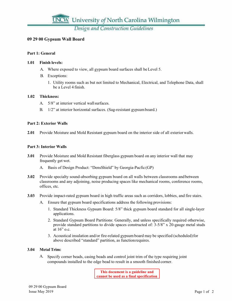
09 29 00 Gypsum BoardIssue May 2019
This document is a guideline and cannot be used as a final specification
Page 1 of 2
09 29 00 Gypsum Wall Board
Part 1: General
1.01 Finish levels: A. Where exposed to view, all gypsum board surfaces shall be Level 5.B. Exceptions:
1. Utility rooms such as but not limited to Mechanical, Electrical, and Telephone Data, shallbe a Level 4 finish.
1.02 Thickness: A. 5/8” at interior vertical wall surfaces.B. 1/2” at interior horizontal surfaces. (Sag-resistant gypsum board.)
Part 2: Exterior Walls
2.01 Provide Moisture and Mold Resistant gypsum board on the interior side of all exterior walls.
Part 3: Interior Walls
3.01 Provide Moisture and Mold Resistant fiberglass gypsum board on any interior wall that may frequently get wet. A. Basis of Design Product: “DensShield” by Georgia-Pacfic (GP)
3.02 Provide specialty sound-absorbing gypsum board on all walls between classrooms and between classrooms and any adjoining, noise producing spaces like mechanical rooms, conference rooms, offices, etc.
3.03 Provide impact-rated gypsum board in high traffic areas such as corridors, lobbies, and fire stairs. A. Ensure that gypsum board specifications address the following provisions:
1. Standard Thickness Gypsum Board: 5/8” thick gypsum board standard for all single-layerapplications.
2. Standard Gypsum Board Partitions: Generally, and unless specifically required otherwise,provide standard partitions to divide spaces constructed of: 3-5/8” x 20-gauge metal studsat 16” o.c.
3. Acoustical insulation and/or fire-related gypsum board may be specified (scheduled) forabove described “standard” partition, as function requires.
3.04 Metal Trim: A. Specify corner beads, casing beads and control joint trim of the type requiring joint
compounds installed to the edge bead to result in a smooth finished corner.
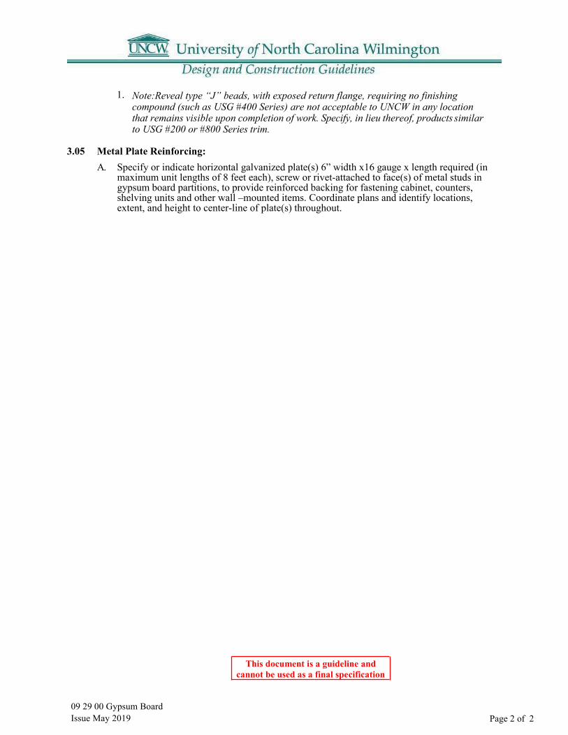
09 29 00 Gypsum Board Issue May 2019
This document is a guideline and cannot be used as a final specification
Page 2 of 2
1. Note:Reveal type “J” beads, with exposed return flange, requiring no finishingcompound (such as USG #400 Series) are not acceptable to UNCW in any locationthat remains visible upon completion of work. Specify, in lieu thereof, products similarto USG #200 or #800 Series trim.
3.05 Metal Plate Reinforcing: A. Specify or indicate horizontal galvanized plate(s) 6” width x16 gauge x length required (in
maximum unit lengths of 8 feet each), screw or rivet-attached to face(s) of metal studs ingypsum board partitions, to provide reinforced backing for fastening cabinet, counters,shelving units and other wall –mounted items. Coordinate plans and identify locations,extent, and height to center-line of plate(s) throughout.
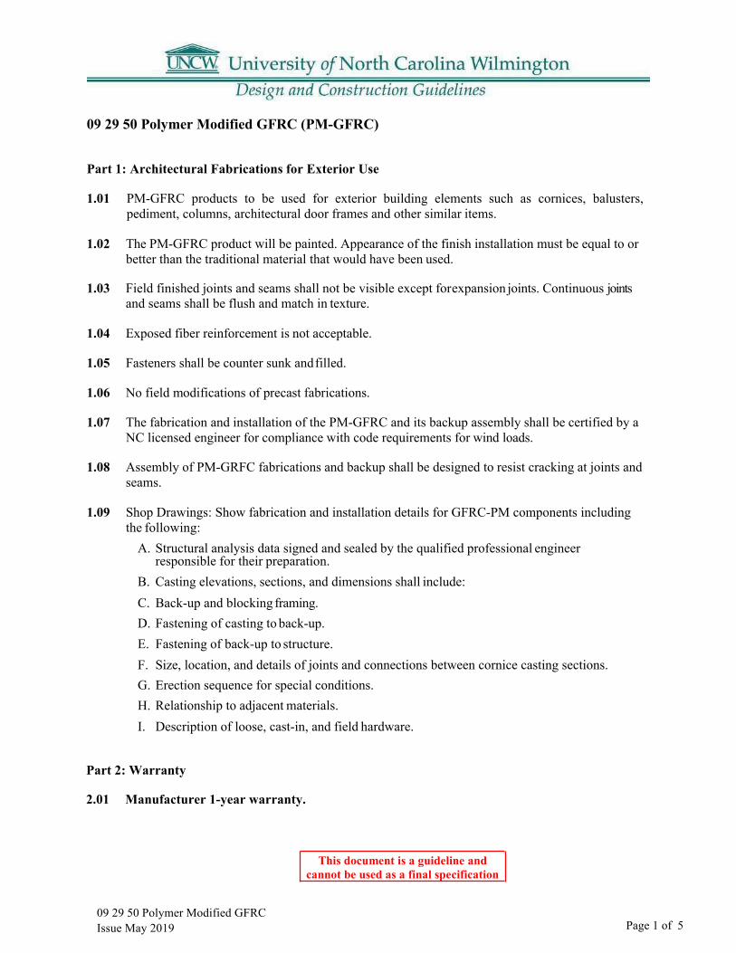
09 29 50 Polymer Modified GFRC Issue May 2019
This document is a guideline and cannot be used as a final specification
Page 1 of 5
09 29 50 Polymer Modified GFRC (PM-GFRC)
Part 1: Architectural Fabrications for Exterior Use
1.01 PM-GFRC products to be used for exterior building elements such as cornices, balusters, pediment, columns, architectural door frames and other similar items.
1.02 The PM-GFRC product will be painted. Appearance of the finish installation must be equal to or better than the traditional material that would have been used.
1.03 Field finished joints and seams shall not be visible except for expansion joints. Continuous joints and seams shall be flush and match in texture.
1.04 Exposed fiber reinforcement is not acceptable.
1.05 Fasteners shall be counter sunk and filled.
1.06 No field modifications of precast fabrications.
1.07 The fabrication and installation of the PM-GFRC and its backup assembly shall be certified by a NC licensed engineer for compliance with code requirements for wind loads.
1.08 Assembly of PM-GRFC fabrications and backup shall be designed to resist cracking at joints and seams.
1.09 Shop Drawings: Show fabrication and installation details for GFRC-PM components including the following:
A. Structural analysis data signed and sealed by the qualified professional engineerresponsible for their preparation.
B. Casting elevations, sections, and dimensions shall include:C. Back-up and blocking framing.D. Fastening of casting to back-up.E. Fastening of back-up to structure.F. Size, location, and details of joints and connections between cornice casting sections.G. Erection sequence for special conditions.H. Relationship to adjacent materials.I. Description of loose, cast-in, and field hardware.
Part 2: Warranty
2.01 Manufacturer 1-year warranty.

Part 3: Design Standard Samples of Original Campus Trimwork that would be reproduced in PM-GFRC.3.01 Column and Cornice Details from Alderman Hall
Cornice Detail from Sheet #11 Alderman Hall
All wood assembly shown. See use of PM-GFRC cornice on next page.
Column Detail from Sheet #12 Alderman Hall
“Temple of the Winds” fluted column shown
This document is a guideline and
09 29 50 Polymer Modified GFRC Issue May 2019
cannot be used as a final specification
Page 2 of 5

09 29 50 Polymer Modified GFRC Issue May 2019
This document is a guideline and cannot be used as a final specification
Page 3 of 5
3.02 Cornice & Parapet Detail from Alderman Hall
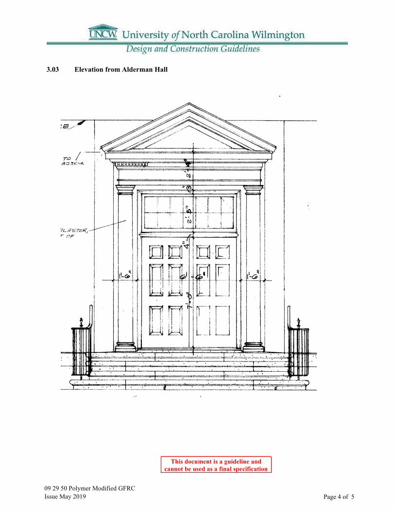
09 29 50 Polymer Modified GFRC Issue May 2019
This document is a guideline and cannot be used as a final specification
Page 4 of 5
3.03 Elevation from Alderman Hall

09 29 50 Polymer Modified GFRC Issue May 2019
This document is a guideline and cannot be used as a final specification
Page 5 of 5
3.04 Elevation from Alderman Hall

This document is a guideline and cannot be used as a final specification
09 51 23 Acoustical Panel Ceiling
Part 1: General
1.01 Determine that acoustical panel ceilings specifications address the following provisions in their correct specification section format locations: A. Submittals:
1. Specify requirements for submission of coordination drawings for reflected ceiling plansdrawn accurately to scale ¼” = 1’-0” indicating penetrations, light fixtures, HVAC outletsand inlets, speakers, sprinkler heads, special moldings at walls, columns, and relationshipwith adjoining materials and planes.
B. Extra Materials:1. Specify delivery of extra stock of suspension system components and acoustical panels in
a quantity not less than 2% of the amount installed.
Part 2: Materials:
2.01 Basis of Design Product shall be “ClimaPlus” series by USG.
09 51 23 Acoustical Panel Ceiling Issue May 2019 Page 1 of 1

This document is a guideline and cannot be used as a final specification
09 65 00 Resilient Flooring
Part 1: General
1.01 Ensure that resilient flooring specifications address the following provisions in their correct specification section format locations: Architects to review the following: A. Extra stock: Specify not less than one box for each 50 boxes, or fraction thereof, for each type,
color, pattern, and size installed.B. Standard size and gauge for vinyl-composition tile at UNCW is 12” x 12” x 1/8” gauge. As
manufactured by Amtico or Farkett or approved equal.C. Specify underlayments over existing wood floors or subfloors as ¼” exterior grade plywood or
7/32” tp ¼” Luaun plywood; ‘Masonite’ is not acceptable.
1.02 Vinyl Cove Base: A.
1.03 Vinyl transition strips/reducer: A. 1/8” or ¼” gaugeB. Color: black or brown.
09 65 00 Resilient Flooring Issue May 2019 Page 1 of 1
4” high, covered over resilient flooring, toeless at carpet flooring. Colors selection is generally made from brown, black, tan and gray.

This document is a guideline and cannot be used as a final specification
09 66 23 Resinous Matrix Terrazzo Flooring
Part 1: Thin-set, epoxy-resin terrazzo flooring
B. Pre-cast Stair Treads and Risers units shall be fabricated using the same material as the floor.C. Thickness: ¾”D. Pre-cast Floor Base units shall be fabricated using the same material as the floor.E. Minimum 3/8-inch thick. Precast units to be cast in maximum lengths possible, but not less
than 36 inches.F. Type: Coved bottom.G. Outside Corner Units: With finished returned edges at outside corner.H. Inside Corner UnitsI. Moisture Vapor Retarding Primer. Provide unit cost for 100% coverage.J. Crack Isolation Membrane. Provide unit cost for 10% coverage.K. Floor Finish and Polishing: Grind and Polish Epoxy-Resin Terrazzo up to the use of 1000
grit pads. The surface shall have a uniform reflective appearance showing no high or lowsheen variances.
1.02 Manufacturer Qualifications: A. Terrazzo materials shall be provided by a manufacturer who is a member of NTMA.
1.03 Installer Qualifications:
A. Engage an installer who is a contractor member of NTMA.B. Engage an installer who is certified in writing by terrazzo manufacturer as qualified to install
Manufacturer’s products.C. Engage a terrazzo contractor with at least five (5) years of satisfactory experience in
installation of epoxy terrazzo. Terrazzo contractor shall demonstrate experience during lastfive (5) years of at least (5) projects of comparable scope and complexity of at least 50percent of the total square footage of this project.
Part 2: Testing of Polished Floor Finish
2.01 Floor finish shall be tested using a recognized testing method. A coefficient of friction of .50 or more is required.
09 66 23 Resinous Matrix Terrazzo Issue May 2019 Page 1 of 1
1.01 A. Thickness: 3/8” (9.5 mm) nominal.

09 86 00 Carpeting Issue May 2019
This document is a guideline and cannot be used as a final specification
Page 1 of 2
09 86 00 Carpeting
Part 1: General 1.01 Ensure that carpet specifications address the following provisions in their correct CSI section
A. Carpet Option #1 Data:B. Basis of Design: Collins & Aikman, “Guardian Plus RS”, or products of other
manufacturers subject to compliance with these requirements:1. Face Construction: Tufted level loop.
a. Tuft must be warrantable wet or dry.2. Face Fiber:3. Face Weight:4. Performance Characteristics:
Dyed nylon similar to Antron II by Dupont Minimum of 26 oz./sq. yd. Soil and stain resistant.
5. Static resistant.6. Colorfast.7. Treated for resistance to bacteria, mold, and mildew.
1.02 Carpet Option #2 Data: A. Basis of Design: Lees Commercial Carpet, “Uni-Bond”, Lifetime warrantyB. Padding:
1. Basis of Design: Collins & Aikman, “Power Bond RS”, or approved equal.C. Specify underlayments over existing wood floors or subfloors as ¼” exterior grade
plywood or 7/32” to ¼” Luaun plywood; ‘Masonite’ is not acceptable.
1.03 Vinyl Cove Base: A. 4” height, toeless at carpet flooring.
1.04 Vinyl Reducer Strip: A. Flexco Co., “Edge Guard #79”, 3/8” undercut, 12’ sections; or products of other
manufacturers complying with product noted.
1.05 Installation A. New Carpet:
1. Direct-glue method. (UNCW does not approve double glue installations).
format locations:
09 86 00 Carpeting Issue May 2019
This document is a guideline and cannot be used as a final specification
Page 2 of 2
1.06 Warranty: 15 years, non-prorated, in writing and notarized A. Warranty Standards – carpet must not:
1. Seam failure – wet or dry2. Zippering – caused by seam failure or tuft failure3. De-lamination of backing – wet or dry whether caused by steam cleaning, wet cleaning,
flooding, or non-use of chair pads4. Carpet pile or backing failure on stair installation
B. In addition to manufacturer’s fiber wear warranty, carpet manufacturer must warrant face fiber and cushion resiliency (crushing) not to exceed 15% over 15 years of 1% per year.
09 91 20 Painting Issue May 2019
This document is a guideline and cannot be used as a final specification
Page 1 of 2
09 91 20 Painting
Part 1: Exterior
1.01 Trimwork: Exterior Latex, Flat A. Color: The basis of design exterior color is “Palais White” SW #2429 by Sherwin
Williams. For interior paint, select from UNCW approved color palette.
Part 2: Interior
2.01 Recommended finishes for given functional spaces: A. Offices:
1. Latex: flat sheen.B. Corridors:
1. Velvet acrylic: low sheen.2. Acrylic latex semi-gloss.
C. Janitor’s Closets:1. Latex semi-gloss.
D. Toilets:1. Latex semi-gloss.
E. Classrooms:1. Velvet acrylic; low sheen.2. Latex semi-gloss.
F. Stairwells/Stairs:1. Stair tread colors shall be carefully selected to provide adequate contrast and allow
for discernment of stairs when ascending and descending.2. Carpet shall not be used in stairwells.3. Latex semi-gloss.
G. Laboratories:1. Alkyd semi-gloss.2. Modified epoxy.3. Urethane fortified high gloss enamel.
H. Animal Research Facilities:1. Modified epoxy.2. Two-component polyamide epoxy.
I. Trim:1. Latex semi-gloss.
09 91 20 Painting Issue May 2019
This document is a guideline and cannot be used as a final specification
Page 2 of 2
2. Latex, high-gloss.J. Mechanical Equipment/Piping:
1. Alkyd semi-gloss.2. Synthetic gloss enamel.
K. Mechanical Rooms:1. Telecommunications terminal boards shall be painted with a fire-retardant type of paint.
L. Common Areas:1. Shall be finished with a semi-gloss paint.
2.02 Colors: A. Coordinate colors with the office of Facilities to ensure that the preferred colors
used throughout the campus are selected.
2.03 Warranty: A. All paint materials and workmanship are subject to a 2-year (24 months) period from the date
of Final Acceptance or Substantial Completion (whichever occurs first), as noted in theGeneral Conditions.
2.04 Manufacturers, Quality Line: A. Provide paint materials of the top-quality line for each manufacturer's paint type, or
materials of other manufacturers subject to compliance with these requirements.

10 11 00 Visual Display Surfaces Issue May 2019
This document is a guideline and cannot be used as a final specification
Page 1 of 1
10 11 00 Visual Display Surfaces
Part 1: Markerboards:
1.01 Face: Porcelain enamel on steel, laminated to core. A. Porcelain Enameled Steel Sheet: ASTM A 424, Type I, Commercial Steel, with fired-on
vitreous finish.B. Color: As selected from manufacturer’s full range.C. Metal Face Sheet Thickness: 0.024 inch (24 gage).
1.02 Core: Particleboard, manufacturer’s standard thickness, laminated to face sheet.
1.03 Backing: Aluminum foil, laminated to core.
1.04 Frame: Extruded aluminum, with concealed fasteners. A. Frame Profile: 5/8-inch mitered corner profileB. Frame Finish: Anodized, natural.
1.05 Accessories: Provide display rail, marker tray and map hooks.
1.06 Basis of Design: “LCS” Series manufactured by Claridge.
Part 2: Tackboards: Fabric laminated to cork.
2.01 Cork Thickness: 7/32 inch.
2.02 Fabric: Vinyl coated fabric.
2.03 Color: As selected from Manufacturer’s full range.
2.04 Backing: Hardboard, ¼ inch thick, laminated to tack surface.
2.05 Frame: Extruded aluminum, with concealed fasteners. A. Frame Profile: Standard 5/8-inch mitered corner profileB. Frame Finish: Anodized, natural.
2.06 Basis of Design: “Fabricork” as manufactured by Claridge.
Part 3: Accessories
3.01 Chalk Tray: Aluminum, manufacturer’s standard profile one length piece for markerboard; molded ends; concealed fasteners, same finish as frame.
3.02 Mounting Brackets: Concealed

10 14 00 Interior & Exterior Signage Issue May 2019
This document is a guideline and cannot be used as a final specification
Page 1 of 11
10 14 00 Signage – Exterior and Interior
Part 1: Interior Signs
1.01 General A. Room Identification and Wayfinding - All campus facilities utilize a uniform methodology
for numbering building rooms and spaces and must comply with a campus standard forinterior signs and directories. See Section 01 00 50 Room Numbering and Wayfinding.
1.02 Design Guidelines A. All building rooms and spaces are to be numbered consistent with UNCW’s room
numbering methodology. See Section 01 00 50 Room Numbering and Wayfinding foradditional information. Room numbers are to be established during the Design Developmentstage consistent with this methodology and continued through Construction Document andConstruction phases.
B. Interior signage shall comply with UNCW Interior Signage Standards.C. The designer shall meet with the UNCW user group, and the Project Manager to develop the
signage package during Construction Document development. During construction, thedesigner shall coordinate with the Contractor and Construction Project Manager and theuser group to re-verify the signage package prior to release for fabrication and installation.
1.03 Special Signs A. ADA: All signage on the project that falls under the jurisdiction of the American with
Disabilities Act is to be provided as required to comply with all applicable requirements ofADA. It is the responsibility of the contractor and the signage manufacturer to ensure thatall signage complies with ADA.
1.04 Construction and Materials A. Provide signage manufactured by a photomechanical (media blast) etching process, leaving
the copy and braille raised. The plaque is then laminated to a 1/8” opaque acrylic base cut tosize and finished with a professional coat of acrylic polyurethane enamel in a selected color.Signs are to be unframed with a square corner with beveled edges.
B. Braille and text are to be raised 1/32”.C. Room Numbers are to be 1”highD. Text is to be 5/8” high on all signs except Sign Type #5. On Sign Type #5 the text is to be 1”
high.E. Letter Style is to be: Standard Bold Condensed – Upper Case LettersF. Finished signs are to be ¼”thickG. Edge Treatment: BeveledH. The signs are to have a square corner with no border.I. The color of the sign is to be silver with black letters, graphics and braille.J. The Grip-Smart Strip is the basis of design. It will be to be clear anodized aluminum finish
with black plastic endcaps.
10 14 00 Interior & Exterior Signage Issue May 2019
This document is a guideline and cannot be used as a final specification
Page 2 of 11
1.05 Submittals A. The contractor shall submit a sample of each type of sign in the specified color and size and
a sample of the Grip-Strip showing its attachment to the appropriate sign type.B. Prior to the installation, the contractor shall supply in duplicate the signage finish schedule
and shop drawings showing the colors, words, numbering and other information to beincluded on the signage as it is to be installed.
1.06 Installation A. The contractor is to install the signage in accordance with the drawings, these specifications,
approved shop drawings and in accordance with manufacturer’s printed instructions. Includeall accessories to provide a proper installation. Work is to be level, plumb and in true plane.Work is to be secure and rigid. Installation accessories shall be furnished by the signagemanufacturer. Do not use installation materials from any other source. Signs adhered toglass shall have a blank plate attached to the back of the glass so that the attaching tape orother method is not visible. The color of the blank plate is to match the sign color. The sizeof the blank plate is to match the size of the sign.
B. The contractor shall supply and install all the graphic inserts (pre-cut and printed) for theType 1 and Type 2 signs. The inserts are to be on paper.
C. Attachment: Per manufacturer recommendation, must be easily removable without damage.D. Signs are to be mounted so that they are ADA compliant.E. The Grip-Strip Sign is to be mounted to the plastic sign and not directly to the wall.F. Any signs that do no remain securely bonded to the substrate for a period of 1 year after
acceptance of the project are to be removed and properly reinstalled at no additional cost tothe owner.
1.07 Manufacturers A. List of UNCW pre-approved manufacturers:
1. Best Sign System2. Corum Signs3. ASI Sign System4. Signature Signs, Inc.5. 290 Sign System
1.08 Sign Type Usage Schedule
Type 1 Type 1 Type 3 Type 4 A, B&C Type 5 Office Conference Rms Classrooms
Photocopy Rms Reception File Room
Housekeeping Mechanical Hazardous Waste Electrical Telecom/Data
Restrooms Direction Department Signs Information Signs Directories
Note: Type 2 has been omitted.
1.09 See SIGNAGE APPENDIX S1 for dimensions of signs.

10 14 00 Interior & Exterior Signage Issue May 2019
This document is a guideline and cannot be used as a final specification
Page 3 of 11
Part 2: Exterior
Signage 2.01 General A. All new building projects and major building renovations require exterior signage. Number
of exterior signs and location of sign to be determined during final design stage.
2.02 Design Guidelines A. All exterior signage shall comply with the UNCW Exterior Signage Standard.B. Color of signs to be: When applied to brick the lettering is white, if applied to white fascia,
the lettering is bronze finish.C. Standard Size:
1. Letters of sign to be ¾” depth, 8” or as directed by PM tall using architectural style –“Prismatic” as manufactured by BFG Industries, Inc. (see Appendix S2)
2. Other Letter Sizes:a. Letter height will be determined by defined wall space available for the text. See
Appendix S2 for average letter width as a space guide.b. Letter distance readability can be determined by chart. (see AppendixS2)
2.03 Quality Assurance A. Manufacturer to have a minimum of 20 years’ experience in manufacturing letters.B. All letters must be manufactured by one manufacturer and must match existing cast
aluminum letters at UNCW facilities - i.e. BFG No. 754 Architectural (prismatic face) letterstyle. (see Appendix S2)
C. A qualified sign installer should install letters.
2.04 Products A. Basis of Design: Provide exterior signs by BFG Industries, Inc., 1057 Colite Drive, West
Columbia, SC 19170 or approved equal based upon specification compliance.
2.05 Materials A. Aluminum ingot for cast aluminum letters - No. 443.1alloy.B. Aluminum extrusion for aluminum sleeve spacers - 6061 or 6063alloy.C. Aluminum all-thread studs for installation hardware for letters up to 16" in height.D. Stainless steel all-thread studs for installation hardware for letters> 18" in height.
2.06 Finishes A. Natural Satin faces, file finished edges, 2-part hardened acrylic polyurethane clearcoat.B. Aliphatic polyurethane enamel equal to DuPont IMRON 3.5 HG paint.
2.07 Mounting Hardware A. Cast aluminum letters have threaded stud bosses for installation stud insertion.B. Letters up to 10" letter height receive 3/16" diameter aluminum studs.
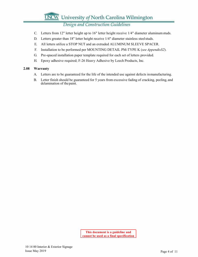
10 14 00 Interior & Exterior Signage Issue May 2019
This document is a guideline and cannot be used as a final specification
Page 4 of 11
C. Letters from 12" letter height up to 16" letter height receive 1/4" diameter aluminum studs.D. Letters greater than 18" letter height receive 1/4" diameter stainless steel studs.E. All letters utilize a STOP NUT and an extruded ALUMINUM SLEEVE SPACER.F. Installation to be performed per MOUNTING DETAIL PM-TYPE K (see AppendixS2).G. Pre-spaced installation paper template required for each set of letters provided.H. Epoxy adhesive required; F-26 Heavy Adhesive by Leech Products, Inc.
2.08 Warranty A. Letters are to be guaranteed for the life of the intended use against defects in manufacturing.B. Letter finish should be guaranteed for 5 years from excessive fading of cracking, peeling, and
delamination of the paint.

10 14 00 Interior & Exterior Signage Issue May 2019
This document is a guideline and cannot be used as a final specification
Page 5 of 11
SIGNAGE
APPENDIX S1

10 14 00 Interior & Exterior Signage Issue May 2019
This document is a guideline and cannot be used as a final specification
Page 6 of 11
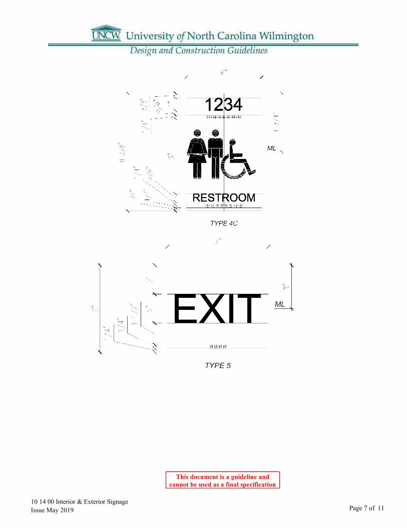
10 14 00 Interior & Exterior Signage Issue May 2019
This document is a guideline and cannot be used as a final specification
Page 7 of 11
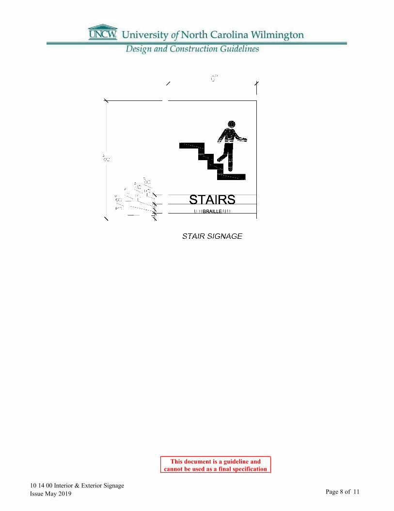
10 14 00 Interior & Exterior Signage Issue May 2019
This document is a guideline and cannot be used as a final specification
Page 8 of 11

10 14 00 Interior & Exterior Signage Issue May 2019
This document is a guideline and cannot be used as a final specification
Page 9 of 11
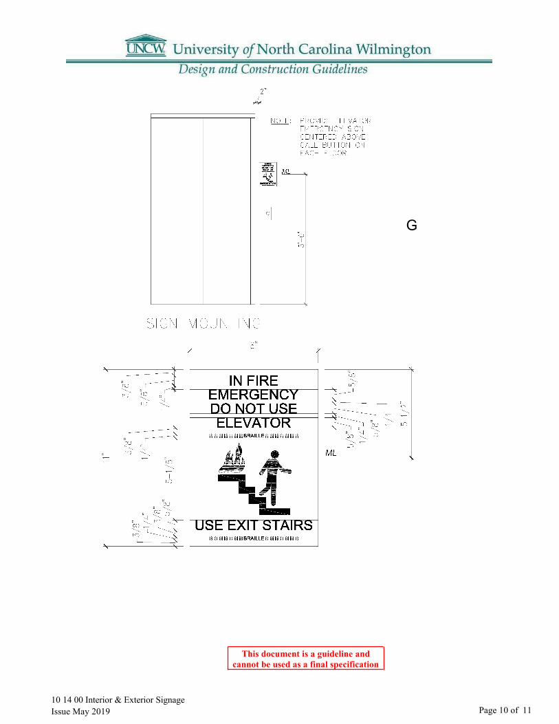
10 14 00 Interior & Exterior Signage Issue May 2019
This document is a guideline and cannot be used as a final specification
Page 10 of 11
ELEVATOR SIGNAGE ANDMOUNTIN G
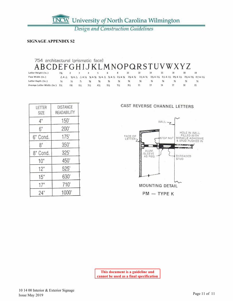
10 14 00 Interior & Exterior Signage Issue May 2019
This document is a guideline and cannot be used as a final specification
Page 11 of 11
SIGNAGE APPENDIX S2

This document is a guideline and cannot be used as a final specification
10 21 13 Toilet and Shower Compartments
Part 1: Toilet Compartments
1.01
1.02 Door and Panel Dimensions A. Door Width: 24 inch.B. Door Width for Handicapped Use: 36 inch, out-swinging.
1.03 Brackets (Fittings): Full-Height (Continuous) Type: Manufacturer's standard aluminum or stainless steel.
1.04 Urinal Screens: Floor and wall mounted.
1.05 Shower Enclosures: Floor mounted, overhead braced.
1.06 Accessories A. Pilaster Shoes: Type 304 stainless steel with No. 4 finish, not less than 0.0312-inch specified
thickness and 3 inches high, concealing floor fastenings.B. Overhead Bracing: Manufacturer's standard continuous, extruded-aluminum head rail with
anti-grip profile and in manufacturer's standard finish.C. Integral shower curtain head rail: Manufacturer’s continuous, extruded aluminum C-channel
rail with nylon glide hook carriers. Provide heavier gauge head rail for longer spans orprovide ceiling mounted center support with concealed fastening. Suspend and brace fromstructure above. Provide flange for supports where they penetrate through ceiling. Finish ofall components is to match headrail.
D. Anchorages and Fasteners: Manufacturer's standard exposed fasteners of stainless-steelfinished to match hardware, with theft-resistant-type heads. Provide hex-type bolts forthrough-bolt applications. For concealed anchors shall also be stainless-steel.
E. The University provides owner standard toilet paper dispensers, soap dispensers, papertowel dispensers and sanitary napkin holders. The contractor installs the owner providedaccessories.
1.07 Hardware: A. All screws and fasteners shall be Stainless-steel.B. Pivot hinges, gravity type, adjustable for door close positioning; two per door.C. Door Latch: Slide type with exterior emergency access feature.D. Door strike and keeper with rubber bumper.E. Coat hook with rubber bumper; one per compartment, mounted on door.
10 21 13 Toilet & Shower Compartments Issue May 2019 Page 1 of 1
Door, Panel and Pilaster Construction: Solid phenolic-core panel material with custom decorative laminate facing on both sides fused to substrate during panel manufacture (not separately laminated), and with eased and polished edges. Provide minimum 3/4-inch- thick doors and pilasters and minimum 1/2-inch- thick panels.

11 00 00 Equipment General Requirements Issue May 2019
This document is a guideline and cannot be used as a final specification
Page 1 of 2
11 00 00 Equipment General Requirements
Part 1: Food Service Equipment:
1.01 (Reserved)
Part 2: Medical Equipment:
2.01 (Reserved)
Part 3: Vacuum Central System:
3.01 Central vacuuming systems will be considered for large areas with fixed seating such as auditoriums and stepped lecture halls.
Part 4: Vending Equipment:
4.01 Vending equipment will be provided by the University. However, the Designer must provide for proper locations and required electrical , plumbing , and network service.
Part 5: Laboratory Equipment:
5.01 The Designer is responsible for determining from the users their specific requirements for the equipment for each laboratory. Since laboratories are highly specialized entities, their equipment needs may be highly complex.
5.02 Design responses may at times be substantially influenced by existing equipment in the case of renovations projects.
Part 6: Waste Handling Equipment:
6.01 The University uses the dumpster system for most ordinary types of collection. This system employs the use of metal containers and a packer truck to mechanically list and dump the cans. The truck requires an overhead clearance of approximately twenty-one feet (verify current vehicle used). The approximate gross weight is 15,000 pounds on the front axle and 38,000 pounds on the rear tandem axles. The roads surface shall be of suitable construction to support the vehicle at its maximum loaded weight. The service road to the container shall have a minimum of twelve-foot width, twenty feet at the curves. The trucks require a forty-five-foot turning radius.
6.02 It is preferred that the rubbish container be located immediately adjacent to the loading platform of the building at a level providing convenient top loading from the platform. A concrete pad shall be provided for each container. The surface of the concrete pad shall be on a plane parallel to the road
11 00 00 Equipment General Requirements Issue May 2019
This document is a guideline and cannot be used as a final specification
Page 2 of 2
surface. Coordinate the required size of pad with the University. Pads shall be a minimum of six inches thick and shall be constructed of reinforced concrete.
6.03 Exterior equipment and trash container areas shall be enclosed with a brick screen wall. A. See section 04 00 00 Masonry.
Part 7: Loading Dock Equipment:
7.01 Loading dock truck bumpers shall be molded rubber or laminated tier cording material. They shall be attached securely to the structure with non-corroding bolts. A. Where appropriate hydraulic or spring-loaded levelers shall be incorporated in the design.
Part 8: Projection Screens:
8.01 See section 11 52 26 Projection Screens
Part 9: Re-Cycling Bins:
9.01 Space shall be allocated for the bins to be placed by the University. The Project Manager should contact Auxiliary Services for an updated transmittal of the current standards.

11 52 26 Projection Screens Issue May 2019
This document is a guideline and cannot be used as a final specification
Page 1 of 1
11 52 26 Projection Screens
Part 1: General
1.01 Basis-of-Design Product: Draper Inc, Access Series V A. Electric motor operatedB. Extruded aluminum housing
1. Recessed mounted.2. Removable bottom closure panel forms slot for passage of viewing surface.3. Color: white
C. Tab tensioned.D. Screen size: As required. See section 27 00 00 UNCW ITSD’s Classroom
Recommendations and Technology Baseline.

This document is a guideline and cannot be used as a final specification
burrs removed. A. Width: 1 inch.B. Thickness: 0.006 inch.C. Color: White
1.02 Slat Support: Woven polypropylene cord, ladder configuration.
1.03 Head Rail: Pre-finished formed aluminum box, with end caps; internally fitted with hardware, pulleys, and bearings for operation; same depth as width of slats. A. Color: same as slats.
1.04 Bottom Rail: Pre-finished, formed aluminum with top side shaped to match slat curvature; with end caps. Color: Same as headrail.
1.05 Lift Cord: Braided nylon; continuous loop. Color: As selected by Architect.
1.06 Control Wand: Extruded hollow plastic; round shape, A. Removable type.B. Length of window opening height less 3 inches.C. Color: White
1.07 Headrail attachment: Wall brackets.
12 21 13 Horizontal Louver Blinds Issue May 2019 Page 1 of 1
Part 1:
1.01 Metal Slats: Spring tempered pre-finished aluminum; radius slat corners, with manufacturing
Horizontal slat louvers hung from full-width headrail with full-width bottom rail; manual control of raising and lowering by cord with full range locking; blade angle adjustable by control wand; complying with WCMA A100.1.
12 21 13 Horizontal Louver Blinds
This document is a guideline and cannot be used as a final specification
12 24 13 Roller Window Shades (Black-out Shades)
Part 1: Roller Assembly
1.01 Basis-of-Design Product: Draper Inc, FlexShade A. Manually operated:
1. Crank and gear boxa. Permanently mounted handleb. Die cast aluminum and steel construction gear box.c. Idler Assembly: provide roller idler assembly of molded nylon with adjustable length
idler pin to facilitate easy installation and removable of shade for service.B. Mounting:
1. Exterior windows: Ceiling mounted2. Interior windows: Wall mounted
C. Color: Headbox and fascia – custom powder coat as selected by Architect.
Part 2: Fabric
A. Black-Out Fabrics1. Basis-of-Design Product: Draper Inc, SunBloc SB9100 Series
a. Opaque shade: white exterior, selected color on interior.B. Light Filtering Fabrics
1. Basis-of-Design Product: Phifer SheerWeave Series SW2400a. 3 percent openb. Greenguard certificationc. Custom color as selected by Architect
12 24 13 Roller Window Shades Issue May 2019 Page 1 of 1

12 93 00 Site Furnishings Issue May 2019
This document is a guideline and cannot be used as a final specification
Page 1 of 7
12 93 00 Site Furnishings
1.01 Seating: Bench Series #C-0
1. Mounting: Surface mounted with stainless steel expansion bolt.
3. Frame: Cast ductile iron supports with lateral supporting steel tube.
A. Basis-of-Design Prod Victor Stanley, Inc. Classic
2. Seat and Back:a. TBD
3. Length: 6 feet.4. Frame Finish: Powder coat
a. Color: Black
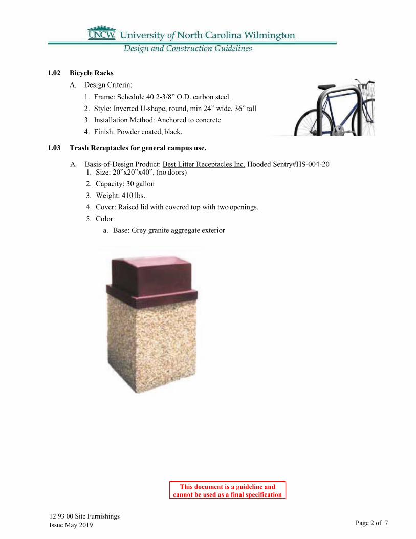
12 93 00 Site FurnishingsIssue May 2019
This document is a guideline and cannot be used as a final specification
Page 2 of 7
1. Size: 20”x20”x40”, (no doors)2. Capacity: 30 gallon3. Weight: 410 lbs.4. Cover: Raised lid with covered top with two openings.5. Color:
a. Base: Grey granite aggregate exterior
1.02 Bicycle Racks A. Design Criteria:
1. Frame: Schedule 40 2-3/8” O.D. carbon steel.2. Style: Inverted U-shape, round, min 24” wide, 36” tall3. Installation Method: Anchored to concrete4. Finish: Powder coated, black.
1.03 Trash Receptacles for general campus use.
A. Basis-of-Design Product: Best Litter Receptacles Inc. Hooded Sentry#HS-004-20

12 93 00 Site FurnishingsIssue May 2019
This document is a guideline and cannot be used as a final specification
Page 3 of 7
1.04 Trash Receptacles for Chancellors Walk. (Reserved) A. Basis-of-Design Product:
1. Size:2. Capacity:3. Weight:4. Cover:5. Color:
1.05 Trash Receptacles for Housing A. Basis-of-Design Product: DuMor Inc, or Victor Stanley, Inc., or Equivalent.
1. Steel Facing Surrounds: Evenly patterned, parallel flat steel straps, bars, or tubular shapes.2. Support Frames: Steel; welded:3. Hurricane rated:4. Steel Finish: Powder coated, color to be determined
1.06 Trash Compactor
A. Basis of Design Product: BigBelly+ SmartBelly, Double Station Solar TrashCompactor, Model # WS-BBSB-DBL-1YR with options.1. Black Hopper with ‘Trashman” Icon2. Blue Faceplate with ‘Bottles, Cans, Paper’ Text3. Blank side skins for Wraps/Panels4. 18” x 30” Messaging Panels for Side Skins with Recycle Inserts

12 93 00 Site Furnishings Issue May 2019
This document is a guideline and cannot be used as a final specification
Page 4 of 7
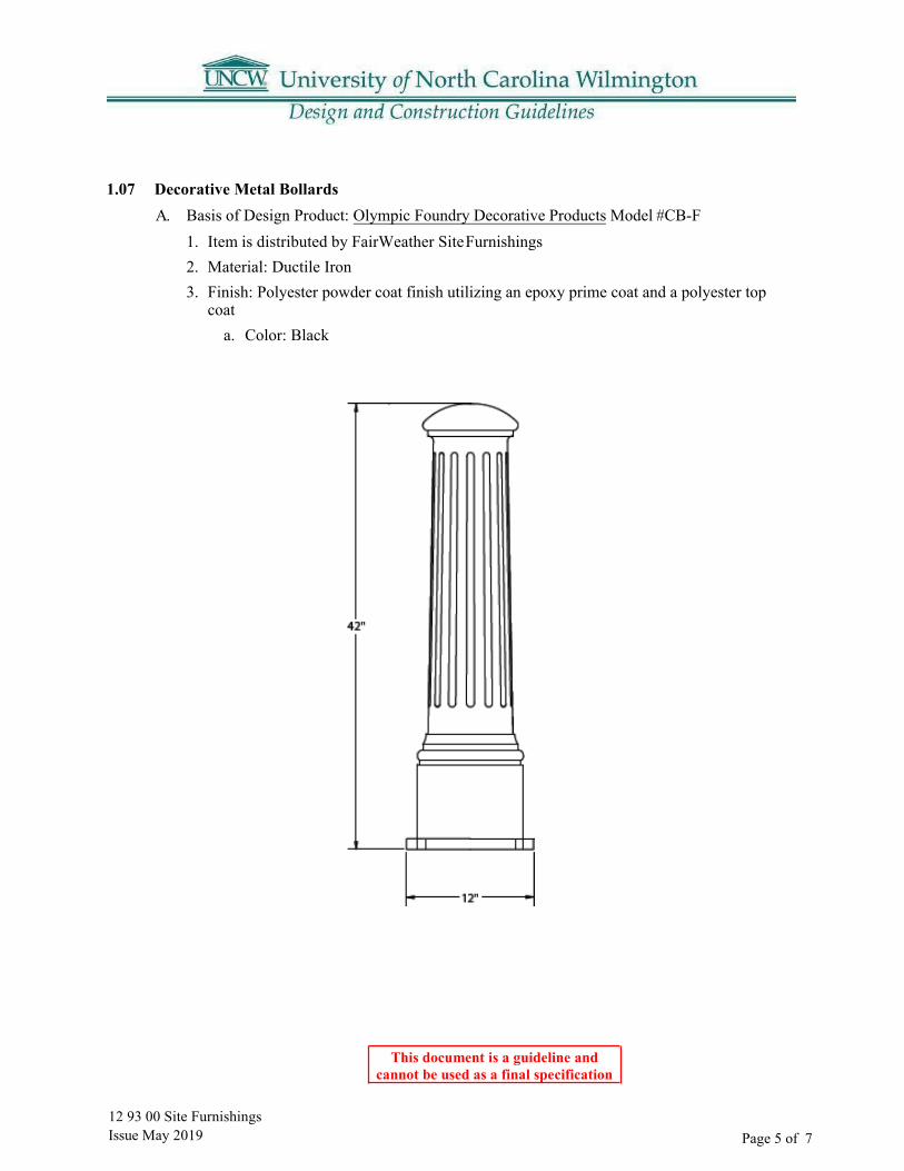
12 93 00 Site Furnishings Issue May 2019
This document is a guideline and cannot be used as a final specification
Page 5 of 7
1.07 Decorative Metal Bollards A. Basis of Design Product: Olympic Foundry Decorative Products Model #CB-F
1. Item is distributed by FairWeather Site Furnishings2. Material: Ductile Iron3. Finish: Polyester powder coat finish utilizing an epoxy prime coat and a polyester top
coata. Color: Black

12 93 00 Site Furnishings Issue May 2019
This document is a guideline and cannot be used as a final specification
Page 6 of 7
1.08 Parking Lot Removable Bollards
Supplier: Creative Fabrications

12 93 00 Site FurnishingsIssue May 2019
This document is a guideline and cannot be used as a final specification
Page 7 of 7
1.09 Bus Shelters A. Preferred alternate: Brasco International - Eclipse Arched1. Color : Black2. Glazing : Clear Tempered Safety Glass3. Include UNCW Logo4. Solar Lighting5. Teal Roof6. Skateboard Deterrent
Page 1 of 114 00 00 Elevator Issue May 2019
This document is a guideline and cannot be used as a final specification
14 00 00 Elevator
Manufacturer’s Warranty: Manufacturer agrees to repair, restore or replace elevator work that fails in materials or workmanship within specified warranty period. Warranty period – one year from date of final acceptance.
The designer should consider the building programming to determine if warranty service is required to be provided without charge 24 hours/day or only during normal business hours.
1.01
1.02

Page 1 of 2 21 10 00 UNCW S ta nda rds f or Fi re Spr inkl er System & Fire Suppression Design & Installations Issue May 2019
21 10 00 Standards for Fire Sprinkler System & Fire Suppression Design & Installation
Part 1: General Standards A. Electric fire pumps only. No diesel fire pumps allowed.B. System design and installation shall comply with the most recent version of the N.C. State
Construction Office document titled “Water Based Fire Protection Systems Guidelines andPolicies”, the most recently adopted version of NFPA 13, and these UNCW design & constructionguidelines. Designers shall closely review all shop drawings and monitor & inspect allinstallations to confirm they meet these criteria and standards.
C. Plastic sprinkler pipe is not allowed.D. All system drains, and inspectors test points must be fully piped to discharge outside the building.
1. Floor drains, hoses, or buckets are not acceptable to use for discharge water or drain water.2. All water flow switches require an inspector’s test valve to be installed and piped to discharge
outside the building.3. Provide a poured concrete splash pad to prevent soil erosion at the discharge of all drain lines
and inspectors test discharge lines.4. Inspectors test valves shall not be installed above ceilings.5. Inspectors test valves shall be operable from standing floor level without the use of ladders.
Maximum height above finished floor to the valve handle is seven feet.E. Pre-action sprinkler valves shall be of the type that do not require removal of covers, face plates,
or apparatus to reset the valve. Other designs are not acceptable. Acceptable manufacturers are“Reliable”, “Tyco”, and “Viking”.
F. Dry pipe sprinkler valves shall be of the external resetting type. Valves that require removal ofcovers, face plates, or apparatus to reset the valve after tripping are not acceptable.
G. The campus standard for pre-action or suppression system releasing control panels is“Notifier” brand control equipment. “Notifier” brand control equipment shall be bid as preferredalternate on all projects that include pre-action sprinkler or clean agent suppression.
H. CO2 fire suppression agent is not allowed. Use other clean agent gasses such as “FM-200”etc.I. “Ansul”, “Kidde”, and “Pyrochem” are acceptable manufacturers of wet chemical, dry chemical,
and clean agent fire suppression equipment.1. Where required, “Guardian series by Safety Solutions International, Inc” brand is the
preferred equipment for residential cooktop wet chemical fire suppression systems.2. Residential wet chemical fire suppression systems, when installed, require automatic release,
a wall mount manual release pull station, and shunt trip equipment to disconnect all power tothe cooktop during agent release.
3. Residential wet chemical fire suppression systems shall be monitored for discharge by thebuilding fire alarm system and shall initiate general alarm.
Page 2 of 2
21 10 00 UNCW S ta nda rds f or Fi re Spr i nkl er System & Fire Suppression Design & Installations Issue May 2019
J. Clean agent fire suppression system designs that requires disconnection of the agentcylinder to weigh the contents for inspection is not acceptable.
K. Wherever possible design elevator machine rooms without the use of dry chemical firesuppression – use wet sprinkler.1. Wherever possible design elevators so that fire sprinklers are not required in the
elevator shaft.L. Water flow detection on wet pipe fire sprinkler systems shall be by vane type flow
switches only. Acceptable manufacturers are “Potter”, “System Sensor”, and “Viking”.“Potter” brand is the campus standard.
M. FDC connections shall use “Storz” type connections.N. Check valves 2.5 inches and larger shall be of the type that have a removable faceplate
cover for access to the valve interior.O. All fire sprinkler piping and control valves shall be installed inside buildings in
conditioned space. PIV valves are the only component allowed outdoors. The use of “hotboxes” for fire sprinkler control valves is not allowed.1. Fire sprinkler control valves shall not be installed above lay-in or dry wall ceilings.2. Fire sprinkler control valves shall be operable from standing floor without the use of
ladders. Maximum height above finished floor to the valve handle is seven feet.3. Install isolation control valves on each floor riser so that individual floors can be
serviced without disrupting fire protection to the other floors of the building.4. Install check valves on each floor riser.
P. Only tankless type air compressors are acceptable for use on dry sprinkler systems.1. Acceptable manufacturers of air compressors for dry type & pre-action sprinkler
systems are “GAST Manufacturing”, “General Air Products”, and “Viking”. “GeneralAir Products” is the campus standard.
2. Acceptable manufacturers of pressure switches for dry type & pre-action sprinklersystems are “Potter”, “System Sensor”, and “Viking”. The campus standard is“Potter”.
Q. “Eaton Cutler Hammer” is the campus standard and of fire pump controller and shall bethe preferred alternate on all projects requiring a fire pump.
R. “Tyco”, “Viking”, “Reliable”, and “Globe” are acceptable manufacturers of fire sprinklerheads.
S. No water driven motor alarm gongs – 24vdc electric water flow bells only.1. Water flow bells shall be powered from and controlled by the fire alarm control panel
through the use of addressable relays.T. Install at least one piping end cap per floor at the furthest point on the run.
1. Install a valved flushing connection on at least one end cap on each floor at thefurthest point on the run-in conjunction with an endcap.
2. Flushing connections must be accessible and not installed above duct work, cabletrays, conduit racks, electrical panels, sheet rock ceilings, or abutted to walls.

22 00 00 General Plumbing Issue May 2019
This document is a guideline and cannot be used as a final specification
Page 1 of 3
22 00 00 General Plumbing
Part 1: Main Campus
1.01 Campus Utilities A. All utilities to a building shall be metered. All meters shall be tied into the building control
system. A bypass that can accommodate full demand shall be provided aroundeach meter.
B. Campus Energy Management Control System1. Two tier architecture.2. First Tier - Tridium Niagra N4 with Energy Analytics software.3. Second Tier
a. Lon communication network with LonWorks certified controllers.b. Modbus communication network for devices that traditionally communicate Modbus
(meters, etc.)C. UNCW owns the domestic water distribution – metering tied into EMCS through the
building’s network area controller.D. UNCW owns the gas distribution – metering tied into EMCS through the building’s network
area controller.E. UNCW owns the main campus electrical distribution - metering from buildings electrical
monitoring system / switchgear / main panels tied into EMCS through the building’s networkarea controller.
F. All underground nonmetallic piping shall have tracer wire.G. All underground piping shall have warning tape installed above it 6” below finish grade.
1.02 Training A. Training shall be provided for the Owner’s employees for all new building equipment to
include variable frequency drives and other major equipment. Training shall be provided by themanufacturer’s representative to the satisfaction of the Owner. Training should include anexplanation of the operational design theory of the system. Training should also address anyvariations from the original design in the construction of the system and their effect on thesystem operation. Training shall be both classroom (which may be provided by the Owner)and “hands on”.
B. Training should be completed one month prior to the beneficial occupancy of the building. Atthe completion of training, The Owner’s personnel shall be able to make
1.03 Mechanical Room Design A. Each building shall have a minimum of one mechanical room providing adequate working
clearances for all equipment. Adequate means of access shall be provided for replacement ofthe largest piece of equipment without removing the walls.
B. All major equipment shall be located at ground level.C. Mechanical rooms shall have a minimum of one each 120-volt electrical receptacle and one
hose bib.

22 00 00 General Plumbing Issue May 2019
This document is a guideline and cannot be used as a final specification
Page 2 of 3
D. Mechanical room floor shall slope to the floor drain. Mechanical rooms shall be providedwith hoist beams or adequate space to install “A” frames for the removal of equipmentsuch as compressors, etc.
E. Overflow lines – All equipment overflow or blow down lines shall be extended to drains.F. Mechanical rooms shall be designed with adequate soundproofing.G. Mechanical rooms shall be accessible by vehicle and shall be provided with service vehicle
parking.H. All boilers and chillers installed on UNCW facilities shall have a manufacturer’s
representative based in reasonable proximity.I. Mechanical Rooms containing chillers, water treatment equipment, hazardous materials
etc., shall be equipped with an eyewash station supplying tepid water and meetingANSIZ358.1
1.04 Additional Design Information Organized by Specification Section
22 05 13 Common Motor Requirements For Plumbing Equipment 1.01 Motors
A. All motors shall be NEMA Premium Efficiency.B. Electric motors of 5 horsepower and larger shall have wiring terminated in the motor
terminal junction box and accomplished with either copper split bolts or ring terminal boltsand nuts. Wire nuts are not acceptable on motors of five (5) horsepower and larger.
C. All motors larger than 15hp should be equipped with a lift eye in the frame of the motor.D. Designers shall specify correct motor horsepower and frame to fit the intended application.
Do not oversize the motor. Service factor on motors to be1.15.E. All motors except light-duty fractional horsepower motors shall be provided with motor
controllers. Controllers shall provide under voltage protection when used with momentarycontact control devices, and under voltage release when used with maintained contactcontrol devices. Motor control devices shall be contained in enclosures that are incompliance with the National Electric Code and NEMA enclosure standards for the intendedapplication.
F. Fractional horsepower motors shall be electronically commutated variable speed.
1.02 VFDs
A. Acceptable manufacturers shall be:1. Danfoss Graham2. ABB3. Honeywell
1.03 VFD ByPass
A. Provide a separately housed manual 3 contactor bypass consisting of a door interlocked main fuseddisconnect pad lockable in the off position, a built-in motor starter, and a four position DRIVE/OFF/LINE/TEST switch controlling three contactors. In the DRIVE position, the motor is operated at an adjustablespeed from the drive. In the OFF position, the motor and the drive are disconnected.
22 00 00 General Plumbing Issue May 2019
This document is a guideline and cannot be used as a final specification
Page 3 of 3
In the LINE position, the motor is operated at full speed from the AC line power and the power is disconnected from the drive, so that service can be performed. In the TEST position, the motor is operated at full speed from the AC line power. This allows the drive to be given an operational test while continuing to run the motor at full speed in bypass. Customer supplied normally closed dry contact shall be interlocked with the drive’s safety trip circuitry to stop the motor whether in DRIVE or BYPASS mode in case of an external safety fault. The use of microprocessor-based bypass control shall not be allowed.
22 05 19 Meters and Gages for Plumbing Equipment Issue May 2019
This document is a guideline and cannot be used as a final specification Page 1 of 1
22 05 19 Meters and Gages for Plumbing Equipment
1.01 Water Meters (Controls Contractor Supplied) A. Water meters shall be provided by the Controls Contractor and must be included in the
Controls specifications.B. Water meters are to be located inside the mechanical room.C. Acceptable meter manufacturers and associated registers:
1. Appropriate Neptune Meter with Neptune: E-Coder register w/ the potted cable(TheR900i register is NOT compatible, since it does not feature a connection wire).
D. Controls Gateway: Meters not having direct Modbus communication shall be integrated tothe Building Management System (BMS) through a Modbus gateway such as a ScadametricsEthermeter http://www.scadametrics.com/ The gateway device shall directly interrogate themeter register and shall calculate and relay the following parameters to the BMS:1. Totalized Volume.2. Instantaneous Flowrate
E. Building Water Meters1. Mechanical Water meters 1.5 inches and below shall be positive displacement type2. Mechanical Water meters above 2 inches and above shall be compound type meter
with matching strainer.F. Irrigation Water Meters
1. Meters shall be minimum 2” turbine meter with matching strainer2. For new buildings and retrofits, we will install the backflow preventers and meters
(including irrigation) inside the building. This will eliminate the need for hotboxesand keep as much controls wiring inside the building as possible.
1.02 Gas Meters (Controls Contractor Supplied) A. Gas Meters shall be Onicon inline insertion meter with D-100 Display. Display shall connect
to BMS via LonB. Controls Gateway: Meters not having direct Modbus communication shall be integrated to
the Building Management System (BMS) through a Modbus gateway such as a ScadametricsEthermeter http://www.scadametrics.com/ The gateway device shall directly interrogate themeter register and shall calculate and relay the following parameters to the BMS:1. Totalized Volume.2. Instantaneous Flowrate

22 05 53 Identification for Plumbing Piping & EquipmentIssue May 2019
This document is a guideline and cannot be used as a final specification Page 1 of 1
22 05 53 Identification for Plumbing Piping and Equipment
1.01 Symbols A. Mechanical and electrical drawing symbols shall be in accordance with guidelines of the
American National Standards Institute (ANSI). The Designer shall uniquely number allmotor driven equipment on the drawings (e.g. for unit heaters, use P-1, P-2, etc. eventhough both of these units are the same size and type).
1.02 Color Standard A. Following is the color standard for mechanical piping identification:
1. Potable Hot and Cold Water and Domestic Hot Water Recirculation -Green2. Non-Potable / Make-Up Water / Grey Water - Purple (Non-Potable / Make-Up Water /
Grey Water must be color coded everywhere in the project)3. Fire Protection – Red4. Natural Gas – Yellow
1.03 Identification Requirements A. Labeling shall be stenciled onto piping.B. Labeling shall include directional arrows.C. The Contractor shall use stencils to identify all such equipment using the numbering
system shown on the drawings. Use oil-based enamel paint with a color that contrasts with theequipment finish. In finished areas, identification shall be located on the insidesurfaces of access doors. In unfinished areas, identify on outside surfaces. Tags may be usedin areas where preferred, but only by using as more permanent method of attachment thanglue or wire.
D. The Electrical Contractor shall identify disconnect devices and starters. Identificationshall be affixed to panel surfaces or to the inside covers when surface mounting isobjectionable.
E. Valve numbers shall be engraved or stamped onto metal plates (1” x 2”) or metal discs (1 ¼”)in diameter attached to the valves by 10-gauge brass “S” hooks. Provide a numbering systemidentifying all valves regardless of valve size or service.
F. Location of all above ceiling equipment is to be marked on the suspended ceiling grid inan unobtrusive manner with engraved phenolic markers.

This document is a guideline and cannot be used as a final specification
22 11 16 Domestic Water Piping
1.01 Materials and Accessories A. All domestic water piping inside the building shall be copper. With written approval PEX-a
may be used in lieu of copper for domestic water pipe less than or equal to 2”.B. All underground PVC piping regardless of use shall have tracer wire.C. Hose bibs will be provided on each side of all buildings. Hose bibs will have detachable
handles or equivalent means to be inaccessible to the general public. They will be equippedwith anti-siphon devices.
D. All backflow preventers should be easily accessible for inspection, maintenance and repair.E. Outdoor Natural Gas and Potable water valves shall be enclosed in a concrete manhole with
a traffic rated lid. The lid shall be 2 inches above finish grade. All valves shall be equippedwith accessible grease fittings.
22 11 16 Domestic Water Piping Issue May 2019 Page 1 of 1

This document is a guideline and cannot be used as a final specification
22 11 23 Domestic Water Pumps
1.01 Motors A. Circulation pumps shall have variable speed Electronically Commutated Motor
(ECM).B. Pump speeds shall not exceed 1760 rpm.
22 11 23 Domestic Water Pumps Issue May 2019 Page 1 of 1

This document is a guideline and cannot be used as a final specification
22 13 16 Sanitary Waste and Vent Piping
1.01 Materials A. All Sanitary and vent piping shall be cast-iron.B. With written approval PVC may be used in lieu of cast-iron pipe for drain, waste or vent
under slab piping.
22 13 16 Sanitary Waste & Vent Piping Issue May 2019 Page 1 of 1

22 13 19 Sanitary Waste Piping Specialties Issue May 2019
This document is a guideline and cannot be used as a final specification Page 1 of 1
22 13 19 Sanitary Waste Piping Specialties
1.01 Floor Drains A. All floor drains shall be of the type which permits removal of the cover only with a
“special tool” or by qualified people.

22 14 13 Facility Storm Drainage Piping Issue May 2019
This document is a guideline and cannot be used as a final specification
Page 1 of 1
22 14 13 Facility Storm Drainage Piping
1.01 Materials A. All underground PVC piping regardless of use shall have tracer wire.

22 42 00 Commercial Plumbing Fixtures Issue May 2019
This document is a guideline and cannot be used as a final specification
Page 1 of 1
22 42 00 Commercial Plumbing Fixtures
1.02 Water Closets A. Water conservation will be considered in the selection of fixtures.B. All fixtures in restrooms shall be of the wall hung variety, not floor mounted.C. Use of automatic flush valves will be considered in design of toilet fixtures.
1.03 Urinals A. Water conservation will be considered in the selection of fixtures.B. All fixtures in restrooms shall be of the wall hung variety, not floor mounted.C. Use of automatic flush valves will be considered in design of toilet fixtures.
1.04 Lavatories A. Water conservation will be considered in the selection of fixtures.B. All fixtures in restrooms shall be of the wall hung variety.
1.05 Sinks A. Water conservation will be considered in the selection of fixtures.B. All fixtures in restrooms shall be of the wall hung variety.C. The basis of design for Janitor’s Mop sinks is a Chicago 952-1/2CP fixture for the DHW
and DCW. Use of a single fixture connected to both hot water and cold water is prohibited.
1.06 Showers, Receptors, Basins A. Water conservation will be considered in the selection of fixtures.
1.07 Wash Fountains A. Water conservation will be considered in the selection of fixtures.
1.08 Medical Plumbing Fixtures A. Water conservation will be considered in the selection of fixtures.
1.09 Emergency Plumbing Fixtures A. Mechanical Rooms containing chillers, water treatment equipment, hazardous materials
etc., shall be equipped with an eyewash station supplying tepid water and meeting ANSIZ358.1.
1.10 Drinking Fountains and Pressure Water Coolers A. In addition to drinking fountains, water bottle filling stations shall be integrated
into the building design.

23 00 00 General Mechanical Issue May 2019
This document is a guideline and cannot be used as a final specification
Page 1 of 3
23 00 00 General Mechanical
Part 1: Main Campus
1.01 Campus Utilities A. UNCW is in the process of centralizing chilled water and heating hot water production in
specific portions of the campus.B. Buildings connecting to a centralized hydronic system shall have a controllable
bridged building loop with its own building pumps. See UNCW chilled water bridgeschematic.
C. All utilities to a building shall be metered. All meters shall be tied into the buildingcontrol system.
D. Campus Energy Management Control System1. Two tier architecture.2. First Tier - Tridium Niagra N4 with Energy Analytics software.3. Second Tier - Lon network with LonWorks certified controllers.4. See control system schematic.
E. UNCW owns the domestic water distribution – metering tied into EMCS through thebuilding’s network area controller.
F. UNCW owns the gas distribution – metering tied into EMCS through the building’s networkarea controller.
G. UNCW owns the main campus electrical distribution - metering from buildings electricalmonitoring system / switchgear / main panels tied into EMCS through the building’s networkarea controller.
H. All underground nonmetallic piping shall have tracer wire.I. All underground piping shall have warning tape installed above it 6” below finish grade.
1.02 Building HVAC A. UNC-Wilmington's standard HVAC system is the fully ducted, centralized, variable volume,
air handling unit serving VAV terminal units with hot water reheat coils. Centralized airhandling units shall have airside enthalpy economizer capability. CO2 monitors shall beutilized to control outside air requirements. Building system shall actively monitor andcontrol humidity as well as temperature. Building system shall actively monitor and controlbuilding pressurization. Total heat recovery shall be utilized. The system shall be fully ductedand insulated on both the supply and return side. Ductwork shall be externally insulated metalductwork. Duct liner is prohibited. Exposed insulation anywhere in the system is prohibited.The use of non-centralized fan powered devices such as fan powered terminal units and fancoil units is typically prohibited and allowed only by permission of the University undercertain circumstances. Assembly spaces such as classrooms and conference rooms shallutilize CO2 or occupancy sensing to put the room into a “standby” mode when the room isscheduled as occupied. Office space shall utilize occupancy sensing.
B. Air handling units shall be double wall construction with no exposed insulating liner.C. Air handling unit fan sections shall utilize direct drive “fan arrays” of
multiple low horsepower fans. Where possible utilize permanent magnetmotors.

23 00 00 General Mechanical Issue May 2019
This document is a guideline and cannot be used as a final specification
Page 2 of 3
D. Air handling unit dampers shall be TAMCO Series 9000 SW with the options ofthermally broken louvers and frames and salt water resistance.
E. Air Handling Unit Mixing boxes shall be constructed that they completely mix outside airwith return air to prevent freezestat trips. Dampers shall be parallel blade design andarranged such that the return air and outside air are directed at each other to aid in mixing.Static diverter blades shall be used to force air mixing.
F. All air handling units shall be set in a metal, water tight auxiliary drain pan. The pan shall bepiped to a floor drain. Float switches will not be used. All air handling units shall havesufficient clearance of all four sides for maintenance. All floor mounted air handling unitsshall have a safe walkway on all four sides.
G. Air handling units shall have a grounded, electrical 120-volt AC outlet within 6 feet of theunit, and a fresh water hose bib with anti-siphon device nearby for coil cleaning. In thecase of adjacent air handlers outlet and hose bib shall be adequate for all units. All airhandling units shall have an on/off switch at the unit that breaks control voltage to thestarter motor. All air handling unit rooms shall have doors appropriately sized forequipment changeouts.
H. Fans units shall be provided with appropriate isolation pads or vibration isolators to suppresstransmission of equipment vibration.
I. Due to the negative pressures inherent in draw through units, all draw through type unitsshall be equipped with Coastguard condensate control devices or approved equal.(asavailable from Trent Technologies).
J. If return air fans are used on the air handling units, they shall be located within the airhandler itself and be supplied with access doors to the motor and fan shaft.
K. The University encourages innovative design but requires such design to meet the approvalof the University.
L. Building HVAC systems must be able to operate under the established requirements of thecentralized chilled water and heating hot water systems.
M. Building stairwells shall be conditioned.N. Mechanical Rooms will be conditioned.O. Location of all above ceiling equipment is to be marked on the suspended ceiling grid in
an unobtrusive manner, e.g. engraved phenolic markers.P. Designer will ensure that outside operating equipment is below noise levels allowed by
local ordinances.Q. Rooms requiring 24-hour conditioning, such as electrical rooms and telecom rooms, shall be
evaluated for its own conditioning system. This will allow the central air handling units to beturned down during unoccupied periods. Systems such as variable refrigerant flow systemshave been used in the past.
1.03 Training A. Training shall be provided for the Owner’s employees for all new building equipment to
include chillers, boilers, control systems, fume hoods, variable frequency drives and other major equipment. Training shall be provided by the manufacturer’s representative to the satisfaction of the Owner. Training should include an explanation of the operational design theory of the system. Training should also address any variations from the original design in the construction of the system and their effect on the system operation. Training shall be both classroom (which may be provided by the Owner) and “hands on”.
23 00 00 General Mechanical Issue May 2019
This document is a guideline and cannot be used as a final specification
Page 3 of 3
B. Training should be completed one month prior to the beneficial occupancy of the building.At the completion of training, the Owner’s personnel shall be able to operate all systems asdesigned.
1.04 Mechanical Room Design A. Each building shall have a minimum of one mechanical room providing adequate working
clearances for all equipment. Adequate means of access shall be provided for replacement of the largest piece of equipment without removing the walls.
B. Mechanical rooms should be tempered (heated, cooled, and dehumidified) to improve equipment operating environment.
C. All major equipment shall be located at ground level.D. Mechanical rooms shall have a minimum of one each 120-volt electrical receptacle and one
hose bib.E. Mechanical room floor shall slope to the floor drain. Mechanical rooms shall be
provided with hoist beams or adequate space to install “A” frames for the removal of equipment such as compressors, etc.
F. Overflow lines – All equipment overflow or blow down lines shall be extended to drains.G. Mechanical rooms shall be designed with adequate soundproofing.H. Mechanical rooms shall be accessible by vehicle and shall be provided with service vehicle
parking.I. Rooftop mounted equipment will be kept to an absolute minimum.J. All chiller rooms shall be equipped with a welding machine electrical outlet.K. All boilers and chillers installed on UNCW facilities shall have a manufacturer’s
representative based in reasonable proximity.L. Mechanical Rooms containing chillers, water treatment equipment, hazardous materials
etc., shall be equipped with an eyewash station supplying tepid water and meeting ANSI Z358.1
1.05 Additional Design Information Organized by Specification Section
23 05 13 Common Motor Requirements for Mechanical EquipmentIssue May 2019
This document is a guideline and cannot be used as a final specification
Page 1 of 1
23 05 13 Common Motor Requirements for Mechanical Equipment
1.01 Motors A. All motors shall be NEMA Premium Efficiency, or where possible, permanent magnet ECM.B. Electric motors of 5 horsepower and larger shall have wiring terminated in the motor
terminal junction box and accomplished with either copper split bolts or ring terminal boltsand nuts. Wire nuts are not acceptable on motors of five (5) horsepower and larger.
C. All motors larger than 15hp should be equipped with a lift eye in the frame of the motor.D. Designers shall specify correct motor horsepower and frame to fit the intended application.
Do not oversize the motor. Service factor on motors to be 1.15.E. All motors except light-duty fractional horsepower motors shall be provided with motor
controllers. Controllers shall provide under voltage protection when used with momentarycontact control devices, and under voltage release when used with maintained contact controldevices. Motor control devices shall be contained in enclosures that are in compliance withthe National Electric Code and NEMA enclosure standards for the intended application.
F. Fractional horsepower motors shall be fully variable speed electronically commutatedmotors.
1.02 VFDs A. Acceptable manufacturers shall be:
1. Honeywell2. Danfoss Graham3. Square D4. ABB5. Cutler Hammer
1.03 VFD ByPass A. Provide a separately housed manual 3 contactor bypass consisting of a door interlocked main
fused disconnect pad lockable in the off position, a built-in motor starter, and a four positionDRIVE/OFF/LINE/TEST switch controlling three contactors. In the DRIVE position, themotor is operated at an adjustable speed from the drive. In the OFF position, the motor andthe drive are disconnected. In the LINE position, the motor is operated at full speed from theAC line power and the power is disconnected from the drive, so that service can beperformed. In the TEST position, the motor is operated at full speed from the AC line power.This allows the drive to be given an operational test while continuing to run the motor at fullspeed in bypass. Customer supplied normally closed dry contact shall be interlocked with thedrive’s safety trip circuitry to stop the motor whether in DRIVE or BYPASS mode in case ofan external safety fault. The use of microprocessor-based bypass control shall not beallowed.

23 05 16 Expansion Fittings & Loops for HVAC PipingIssue May 2019
This document is a guideline and cannot be used as a final specification
Page 1 of 1
23 05 16 Expansion Fittings and Loops for HVAC Piping
1.01 Expansion Guidelines A. Mechanical expansion devices are not allowed. Pipe loops shall be used.

23 05 19 Meters & Gages for HVAC Piping Issue May 2019
This document is a guideline and cannot be used as a final specification
Page 1 of 1
23 05 19 Meters and Gages for HVAC Piping
1.01 General
A. All meters shall be tied to the local area controller. Instantaneous and where required,totalized flow shall be relayed to the BMS.
B. BTU Meters: Onicon System-10 BTU meter, LonWorks communication, F-3500Electromagnetic Flow Meter.

23 05 23 General Duty Valves for HVAC Piping Issue May 2019
This document is a guideline and cannot be used as a final specification
Page 1 of 1
23 05 23 General Duty Valves for HVAC Piping
1.01 Gas Valves A. Outdoor Natural Gas valves shall be enclosed in a concrete manhole with a traffic rated
lid. The lid shall be 2 inches above finish grade. All valves shall be equipped withaccessible grease fittings.
23 05 53 Identification for HVAC Piping & EquipmentIssue May 2019
This document is a guideline and cannot be used as a final specification
Page 1 of 1
23 05 53 Identification for HVAC Piping and Equipment
1.01 Symbols A. Mechanical and electrical drawing symbols shall be in accordance with guidelines of the
American National Standards Institute (ANSI). The Designer shall uniquely number allmotor driven equipment on the drawings (e.g. for unit heaters, use UH-1, UH-2, etc. eventhough both of these units are the same size and type).
1.02 Color Standard A. Following is the color standard for mechanical piping identification:
1. Chilled Water Supply and Return - Dark Blue2. Condenser / Tower Water Supply and Return - Light Blue3. Heating Hot Water Supply and Return – Orange4. Natural Gas – Yellow
1.03 Identification Requirements A. Labeling shall be stenciled onto piping.B. Labeling shall include directional arrows.C. The Contractor shall use stencils to identify all such equipment using the numbering
system shown on the drawings. Use oil-based enamel paint with a color that contrasts withthe equipment finish. In finished areas, identification shall be located on the insidesurfaces of access doors. In unfinished areas, identify on outside surfaces. Tags may beused in areas where preferred, but only by using as more permanent method of attachmentthan glue or wire.
D. The Electrical Contractor shall identify disconnect devices and starters. Identificationshall be affixed to panel surfaces or to the inside covers when surface mounting isobjectionable.
E. Valve numbers shall be engraved or stamped onto metal plates (1” x 2”) or metal discs (1 ¼”)in diameter attached to the valves by 10-gauge brass “S” hooks. Provide a numbering systemidentifying all valves regardless of valve size or service.
F. Location of all above ceiling equipment is to be marked on the suspended ceiling grid inan unobtrusive manner, e.g. small color-coded dots.

This document is a guideline and cannot be used as a final specification
23 05 93 Testing, Adjusting and Balancing for HVAC
1.01 General A. Per project requirements.
23 05 93 Testing, Adjusting & Balancing for HVACIssue May 2019 Page 1 of 1
This document is a guideline and cannot be used as a final specification
23 07 16 HVAC Equipment Insulation
1.01 Air Handlers A. Units shall be double walled with no insulation exposed to system air.
23 07 16 HVAC Equipment Insulation Issue May 2019 Page 1 of 1

This document is a guideline and cannot be used as a final specification
23 07 19 HVAC Piping Insulation
1.01 Hydronic piping A.
23 07 19 HVAC Piping Insulation Issue May 2019 Page 1 of 1
Insulation to be preformed fiberglass. Indoor covers to be color coded PVC jacket and outdoor covers to be aluminum.

Page 1 of 24 23 09 00 Control SpecificationsIssue May 2019
23 09 00 Control Specifications Part 1 General 1.01 Section Includes
A. Building Management System (BMS), utilizing direct digital controls.1.02 Related Work Specified Elsewhere
A. Products Supplied But Not Installed Under This Section:1. Control valves.2. Flow switches.3. Wells, sockets and other inline hardware for water sensors (temperature, pressure, flow).4. Automatic control dampers, where not supplied with equipment.5. Airflow measuring stations.6. Terminal unit controllers and actuators, when installed by terminal unit manufacturer.7. Variable frequency drives. (This does not include VFDs integral to machinery such as chillers or
boilers).8. In-line meters (gas, water, power, BTU).
B. Products Installed But Not Supplied Under This Section:1. None.
C. Products Not Furnished or Installed But Integrated with the Work of This Section:2. Refrigerant monitors.3. Smoke detectors (through alarm relay contacts).4. Chiller Control Systems.5. Boiler Control Systems.6. Pump Control Packages.7. Chemical Water Treatment.
D. Work Required Under Other Divisions Related to This Section:1. Power wiring to line side of motor starters, disconnects or variable frequency drives.2. Provision and wiring of smoke detectors and other devices relating to fire alarm system.3. Campus LAN (Ethernet) connection adjacent to JACE network management controller.
1.03 System Description A. Scope: Furnish all labor, materials and equipment necessary for a complete and operating Building
Management System (BMS), utilizing Direct Digital Controls as shown on the drawings and asdescribed herein. Drawings are diagrammatic only. All controllers furnished in this section shallcommunicate on a peer-to-peer bus over a LonTalk, BACnet, or IP Based open protocol bus. Allcontrollers on the LonTalk bus shall be LonMark certified.
1. The intent of this specification is to provide a system that is consistent with BMS systemsthroughout the owner's facilities running the Niagara 4 Framework.
2. System architecture shall fully support a multi-vendor environment and be able to integratethird party systems via existing vendor protocols including, as a minimum, LonTalk,BACnet and MODBUS.
3. Acceptable specific vendor circumstances for protocol requirement such as Mitshibishi VRFSystem to b BACnet or Modbus interfaced to the BAS Niagara system from the factoryprotocol.
4. System architecture shall provide secure Web access using any of the current versions ofMicrosoft Internet Explorer, Mozilla Firefox, or Google Chrome browsers from anycomputer on the owner's LAN.
5. All control devices, including configurable and fully programmable controllers, furnished withthis Section shall be programmable directly from the Niagara 4 Workbench embedded toolsetupon completion of this project. The use of configurable or programmable controllers thatrequire additional software tools shall not be acceptable.
6. Any control vendor that shall provide additional BMS server software shall be unacceptable.Only systems that utilize the Niagara 4 Framework shall satisfy the requirements of thissection.

23 09 00 Control Specifications Issue May 2019 Page 2 of 24
. 7. The BMS server shall host all graphic files for the control system. All graphics and
navigation schemes for this project shall match those that are on the existing campusNiagaraAX or Niagara 4 Framework server.
8. A new laptop computer including engineering/programming software to modifyOperating System Server BMS programs and graphics shall be included. An IPAD maybe requested for monitoring of building operations and graphic access and will be jobspecific per a request by UNCW if required(Owner’s discrepancy)
9. Owner shall receive all Administrator level login and passwords for engineering toolsetat first training session. The Owner shall have full licensing and full access rights for allnetwork management, operating system server, engineering and programming softwarerequired for the ongoing maintenance and operation of the BMS. UNCW will beresponsible for setting up desired user accounts with necessary access limits per eachuser’s requirements and allowances.
10. OPEN NIC STATEMENTS - All Niagara 4 software licenses shall have the followingNiCS: "accept.station.in=*"; "accept.station.out=*"and "accept.wb.in=*"and"accept.wb.out=*". All open NIC statements shall follow Niagara Open NICspecifications.
11. All JACE hardware licenses and certificates shall be stored on local MicroSD memorycard employing encrypted “safe boot” technology.
12. All JACE’s provided as part of this project shall be the appropriate JACE-8000 modellicensed with all necessary drivers.
13. Approved Manufacturers: Honeywell, TAC I/A Series, Distech, Trane.14. Approved Installation Contractors: Engineered Control Solutions, Brady Service, CMS
Controls.1.04 Specification Nomenclature
A Acronyms used in this specification are as follows: 1. Actuator: Control device that opens or closes valve or damper in response to control signal.2. AI: Analog Input.3. AO: Analog Output.4. Analog: Continuously variable state overstated range of values.5. BMS: Building Management System.6. DDC: Direct Digital Control.7. Discrete: Binary or digital state.8. DI: Discrete Input.9. DO: Discrete Output.10. FC: Fail Closed position of control device or actuator. Device moves to closed position on loss of
control signal or energy source.11. FO: Fail open (position of control device or actuator). Device moves to open position on loss of
control signal or energy source.12. GUI: Graphical User Interface.13. HVAC: Heating, Ventilating and Air Conditioning.14. IDC: Interoperable Digital Controller.15. ILC: Interoperable Lon Controller.16. LAN: Local Area Network.17. Modulating: Movement of a control device through an entire range of values, proportional to an
infinitely variable input value.18. Motorized: Control device with actuator.19. NAC: Network Area Controller.20. NC: Normally closed position of switch after control signal is removed or normally closed
position of manually operated valves or dampers.

23 09 00 Control Specifications Issue May 2019 Page 3 of 24
21. NO: Normally open position of switch after control signal is removed; or the openposition of a controlled valve or damper after the control signal is removed; or the usualposition of a manually operated valve.
22. OSS: Operating System Server, host for system graphics, alarms, trends, etc.23. Operator: Same as actuator.24. PC: Personal Computer.25. Peer-to-Peer: Mode of communication between controllers in which each device
connected to network has equal status and each shares its database values with all otherdevices connected to network.
26. P: Proportional control; control mode with continuous linear relationship betweenobserved input signal and final controlled output element.
27. PI: Proportional-Integral control, control mode with continuous proportional output plusadditional change in output based on both amount and duration of change in controllervariable (reset control).
28. PICS: BACnet Product Interoperability Compliance Statement.29. PID: Proportional-Integral-Derivative control, control mode with continuous correction
of final controller output element versus input signal based on proportional error, itstime history (reset) and rate at which it's changing (derivative).
30. Point: Analog or discrete instrument with addressable database value.31. WAN: Wide Area Network.
1.05 Submittals A. Submit under provisions of Section 01 30 00.B. Product Data: Manufacturer's data sheets on each product to be used, including:
1. Preparation instructions and recommendations.2. Storage and handling requirements and recommendations.3. Installation methods.
C. Submit documentation of contractor qualifications, including those indicated in "QualityAssurance" if requested by the A-E.
D. (X) copies of shop drawings of the entire control system shall be submitted and shallconsist of a complete list of equipment and materials, including manufacturers' catalog datasheets and installation instructions. Submit in printed electronic format. Samples of writtenController Checkout Sheets and Performance Verification Procedures for applicationssimilar in scope shall be included for approval.
E. Shop drawings shall also contain complete wiring and schematic diagrams, sequences ofoperation, control system bus layout and any other details required to demonstrate that thesystem has been coordinated and will properly function as a system. Terminal identificationfor all control wiring shall be shown on the shop drawings.
F. Upon completion of the work, provide (x) complete sets of ' as-built' drawings and otherproject- specific documentation in 3-ring hard-backed binders and one electronic copy.
G. Any deviations from these specifications or the work indicated on the drawings shall beclearly identified in the Submittals.
H. All control panels associated with a field device such as air handlers and water systemsshall have a laminated page copy of the writing schematic and detail attached to the controlcabinet.
I. A software copy of the controls as-built shall be supplied and downloaded to the localsystem network controller (SNC) in 2 different formats. One PDF format and another in theformat (Visio) used to produce and engineer the original document as to allow UNCW tomodify the as-builts in future changes, construction, and modifications to the controlssystem.

23 09 00 Control Specifications Issue May 2019 Page 4 of 24
1.06 Quality Assurance A. The Control System Contractor shall have a full service DDC office within 50 miles of the
job site. This office shall be staffed with applications engineers, software engineers andfield technicians. The Control System Contractor shall be staffed with a minimum of ten(10) Niagara 4 certified software engineers and/or technicians. The Control SystemContractor shall maintain parts inventory and shall have all testing and diagnosticequipment necessary to support this work, as well as staff trained in the use of thisequipment.
B. Single Source Responsibility of Supplier: The Control System Contractor shall beresponsible for the complete installation and proper operation of the control system. TheControl System Contractor shall exclusively be in the regular and customary business ofdesign, installation and service of computerized building management systems similar insize and complexity to the system specified. The Control System Contractor shall be themanufacturer of the primary DDC system components or shall have been the authorizedrepresentative for the primary DDC components manufacturer for at least 10 years. Allcontrol panels shall be assembled by the Control System Contractor in a UL- Certified508A panel shop. Control panels shall be assembled such that all necessary I/O points arepre-wired to terminal blocks. Wire ducts shall be installed within the panel as needed toaccommodate field wiring.
C. Equipment and Materials: Equipment and materials shall be cataloged products ofmanufacturers regularly engaged in the production and installation of HVAC controlsystems. Products shall be manufacturer's latest standard design and have been tested andproven in actual use.
1.07 Software Ownership A. The Owner shall have full ownership and full access rights for all network management,
operating system server, engineering and programming software required for theongoing maintenance and operation of the BMS.
1.08 Delivery, Storage & Handling A. Maintain integrity of shipping cartons for each piece of equipment and control device
through shipping, storage and handling as required to prevent equipment damage.Store equipment and materials inside and protected from weather.
1.09 Job Conditions A. Cooperation with Other Trades: Coordinate the Work of this section with that of other
sections to insure that the Work will be carried out in an orderly fashion. It shall be thisContractor's responsibility to check the Contract Documents for possible conflictsbetween his Work and that of other crafts in equipment location, pipe, duct and conduitruns, electrical outlets and fixtures, air diffusers and structural and architectural features.
1.10 Sequencing A. Ensure that products of this section are supplied to affected trades in time to prevent
interruption of construction progress. Part 2 Products
2.01 General A. The Building Management System (BMS) shall be comprised of a network of
interoperable, stand- alone digital controllers, a network area controller, graphics andprogramming and other control devices for a complete system as specified herein.
B. The installed system shall provide secure strong password access to all features,functions and data contained in the overall BMS.

23 09 00 Control Specifications Issue May 2019
Page 5 of 24
2.02 Open, Interoperable, Intergrated Architecture A. The intent of this specification is to provide a peer-to-peer networked, stand-alone, distributed
control system utilizing the LonWorks technology communication protocol in one open,interoperable system.
B. The supplied computer software shall employ object-oriented technology (OOT) forrepresentation of all data and control devices within the system. Physical connection of anyBACnet control equipment, such as chillers, shall be via Ethernet or IP.
C. All components and controllers supplied under this contract shall be true "peer-to-peer"communicating devices. Components or controllers requiring "polling" by a host to pass datashall not be acceptable.
D. The supplied system shall incorporate the ability to access all data using HTML5 enabledbrowsers without requiring proprietary operator interface and configuration programs orbrowser plug-ins. An Open Database Connectivity (ODBC) or Structured Query Language(SQL) compliant server database is required for all system database parameter storage. Thisdata shall reside on the Operating System Server located in the Facilities Office on the LAN.Systems requiring proprietary database and user interface programs shall not be acceptable.
E. A hierarchical topology is required to assure reasonable system response times and to managethe flow and sharing of data without unduly burdening the customer's internal Intranetnetwork. Systems employing a "flat" single tiered architecture shall not be acceptable.1. Maximum acceptable response time from any alarm occurrence (at the point of origin)
to the point of annunciation shall not exceed 5 seconds for network connected userinterfaces.
2. Maximum acceptable response time from any alarm occurrence (at the point of origin)to the point of annunciation shall not exceed 60 seconds for remote or dial-up connecteduser interfaces.
2.03 BAS Server Hardware (Provided by Owner) A. Minimum Computer Configuration (Hardware Independent).
1. Central Server. Owner shall provide a dedicated BAS server with configuration thatincludes the following components as a minimum:
2. Processor: Intel Xeon CPU E5-2640 x64 (or better), compatible with dual- and quad-core processors.
3. Memory: 8 GB or more.4. Hard Drive: 80 GB minimum, more recommended depending on archiving
requirements.5. Display: Video card and monitor capable of displaying 1024 x 768 pixel resolution or
greater.6. Network Support: Ethernet adapter (10/100 Mb with RJ-45 connector).7. Connectivity: Full-time high-speed ISP connection recommended for remote site
access (i.e. T1, ADSL, cable modem).B. Standard Client: The thin-client Web Browser BAS GUI shall be Microsoft Internet Explorer
(10.0 or later) running on Microsoft 7+. No special software shall be required to be installedon the PCs used to access the BAS via a web browser.

23 09 00 Control Specifications Issue May 2019 Page 6 of 24
2.04 System Network Controller (SNC) A. These controllers are designed to manage communications between the programmable
equipment controllers (PEC), application specific controllers (ASC) and advanced unitarycontrollers (AUC) which are connected to its communications trunks, managecommunications between itself and other system network controllers (SNC) and with anyoperator workstations (OWS) that are part of the BAS, and perform control and operatingstrategies for the system based on information from any controller connected to the BAS.
B. The controllers shall be fully programmable to meet the unique requirements of the facility itshall control.
C. The controllers shall be capable of peer-to-peer communications with other SNC's and withany OWS connected to the BAS, whether the OWS is directly connected, connected viacellular modem or connected via the Internet.
D. The communication protocols utilized for peer-to-peer communications between SNC's willbe Niagara 4 Fox, BACnet TCP/IP and SNMP. Use of a proprietary communicationprotocol for peer-to- peer communications between SNC's is not allowed.
E. The SNC shall employ a device count capacity license model that supports expansioncapabilities.
F. The SNC shall be enabled to support and shall be licensed with the following Open protocoldrivers (client and server) by default:1. BACnet2. Lon3. MODBUS4. SNMP5. KNX
G. The SNC shall be capable of executing application control programs to provide:1. Calendar functions.2. Scheduling.3. Trending.4. Alarm monitoring and routing.5. Time synchronization.6. Integration of LonWorks, BACnet, and MODBUS controller data.7. Network management functions for all SNC, PEC and ASC based devices.
H. The SNC shall provide the following hardware features as a minimum:1. Two 10/100 Mbps Ethernet ports.2. Two Isolated RS-485 ports with biasing switches.3. 1 GB RAM4. 4 GB Flash Total Storage / 2 GB User Storage5. Wi-Fi (Client or WAP)6. USB Flash Drive7. High Speed Field Bus Expansion8. -20-60°C Ambient Operating Temperature9. Integrated 24 VAC/DC Global Power Supply10. MicroSD Memory Card Employing Encrypted Safe Boot Technology
I. The SNC shall be installed with a UPS battery backup with a minimum specificationrating of 600VA/300W and surge protection mounted in or next to the SNC main panel.
J. The SNC shall provide alarm recognition, storage, routing, management and analysis tosupplement distributed capabilities of equipment or application specific controllers.

23 09 00 Control Specifications Issue May 2019 Page 7 of 24
K. The SNC shall be able to route any alarm condition to any defined user location whetherconnected to a local network or remote via cellular modem, or wide-area network.1. Alarm generation shall be selectable for annunciation type and acknowledgement
requirements including but not limited to:a. Alarm.b. Return to normal.c. To default.
2. Alarms shall be annunciated in any of the following manners as defined by the user:a. Screen message text.b. Email of complete alarm message to multiple recipients.c. Pagers via paging services that initiate a page on receipt of email message.d. Graphics with flashing alarm object(s).
3. The following shall be recorded by the SNC for each alarm (at a minimum):a. Time and date.b. Equipment (air handler #, access way, etc.).c. Acknowledge time, date, and user who issued acknowledgement
4. Alarms classes shall be created in the local station to match N4 Supervisor class namingin the following manner with same naming for priority routing and annunciation. (listedin order of priority from highest to lowest)a. Critical Alarms (Priority 1)b. High Priority (Priority 2)c. Space Temp Alarms (Priority 3)d. Generator Alarms (Priority 3) (if required)e. Plumbers Alarms (Priority 3) (if required)f. Mid Priority (Priority 4)g. Low Priority (Priority 5)h. Ping Alarms (Priority 6)i. *Back to normal state (Priority 7)*
5. All alarm classes in the local station shall be directed to the N4 station recipient forrouting. The Supervisors “Supervisor Console” should be added to a Px view accessiblevia a hyperlink with a filter applied to show only the selected buildings alarms on theappropriate buildings graphics alarm page.a. Time Stampb. Sourcec. Source Stated. Alarm Statee. Priorityf. Alarm Classg. Ack or Clear Action link
L. Programming software and all controller "Setup Wizards" shall be embedded into the SNC.M. The SNC shall support the following security functions.
1. Module code signing to verify the author of programming tool and confirm that thecode has not been altered or corrupted.
2. Role-Based Access Control (RBAC) for managing user roles and permissions.3. Require users to use strong credentials.4. Data in Motion and Sensitive Data at Rest be encrypted.5. LDAP and Kerberos integration of access management.

N. The SNC shall support the following data modeling structures to utilize Search; Hierarchy;Template; and Permission functionality:1. Metadata: Descriptive tags to define the structure of properties.2. Tagging: Process to apply metadata to components3. Tag Dictionary
O. The SNC shall employ template functionality. Templates are a containerized set ofconfigured data tags, graphics, histories, alarms... that are set to be deployed as a unit basedupon manufacturer’s controller and relationships. All lower level communicating controllers(PEC, AVAV, CVAV, VFD) shall have an associated template file for reuse on futureproject additions.
P. The SNC point naming shall follow a standard as set for a standardized naming convention.This naming standard shall be applied to the SNC as well as the BAS Server Supervisor forall points related to setpoints, monitoring points, trending, alarming, and graphics.
Q. The SNC shall be provided with a 1 Year Software Maintenance license. Labor toimplement not included.
2.05 Building Automation System Controllers A. HVAC local programmable and configurable controller’s communications protocol (AHU,
VAV, and plant) shall be accomplished using LonMark, BACnet, or IP based devices. Thecontroller platform shall provide options and advanced system functions, programmable andconfigurable using Niagara 4 Framework, that allow standard and customizable controlsolutions required in executing the "Sequence of Operation".1. Programmable Equipment Controllers - a controller designed for more complex
sequences of operations such as built up AHU’s, central plant operations, electricalmonitoring, and control and management for chillers, boilers and generators. The PECsare to allow for the flexibility of custom control programming to meet the neededsequences of operation. PEC’s shall be selected based upon I/O requirements. AdditionalI/O may be added via expansion modules.a. All PECs shall be application programmable and shall at all times maintain their
certification. All control sequences within or programmed into the PEC shall bestored in non-volatile memory, which is not dependent upon the presence of abattery to be retained.
b. The PEC shall provide LED indication of communication and controllerperformance to the technician, without cover removal.
c. PEC’s shall have mixture of I/O including dry contact digital inputs, universalinputs (configurable as 0-10V, 0-10,000 ohm or, 20K NTC), analog outputs (4-20mA), and digital outputs (24 VAC TRIAC or relay).
2. Advanced Variable Air Volume Controller (AVAV) - a controller designed specificallyfor room-level VAV control - pressure-independent air flow control, pressure dependentdamper control, supply and exhaust pressurization/de-pressurization control; temperature,humidity, complex CO2, occupancy, and emergency control. Equipment includes: VAVterminal unit, VAV terminal unit with reheat, series fan powered terminal unit, parallelfan powered terminal unit, supply and exhaust air volume terminals and constant volumedual-duct terminal unit.a. The AVAV shall be application programmable and shall at all times maintain their
certification. All control sequences within or programmed into the PEC shall bestored in non-volatile memory, which is not dependent upon the presence of abattery to be retained.
b. The controller shall have an internal velocity pressure sensor.c. The AVAV shall provide LED indication of communication and controller
performance to the technician, without cover removal.
Page 8 of 2423 09 00 Control SpecificationsIssue May 2019
d. AVAV’s shall have mixture of I/O including dry contact digital inputs, universalinputs (configurable as 0-10V, 0-10,000 ohm or, 20K NTC), analog outputs (4-20mA), and digital outputs (24 VAC TRIAC).
e. The controller shall provide an integrated actuator option.3. Configurable VAV Controller (CVAV) - the configurable VAV controller platform shall
be designed specifically for room-level VAV control – pressure-independent air flowcontrol, pressure dependent damper control, supply and exhaust pressurization/de-pressurization control; temperature, humidity, complex CO2, occupancy, and emergencycontrol. Equipment includes: VAV terminal unit, VAV terminal unit with reheat, seriesfan powered terminal unit, parallel fan powered terminal unit, supply and exhaust airvolume terminals, and constant volume dual-duct terminal unit.a. The CVAV shall be application specific configuration and shall at all times maintain
their certification. All control sequences within or programmed into the CVAV shallbe stored in non-volatile memory, which is not dependent upon the presence of abattery to be retained.
b. The controller shall have an internal velocity pressure sensor.c. The CVAV shall provide LED indication of communication and controller
performance to the technician, without cover removal.d. CVAV’s shall have mixture of I/O including dry contact digital inputs, universal
inputs (configurable as 0-10V, 0-10,000 ohm or, 20K NTC), analog outputs (4-20mA), and digital outputs (24 VAC TRIAC).
e. The controller shall provide an integrated actuator option.4. Configurable Constant Volume AHU Controller (CVAHU) - the configurable constant
volume AHU controller shall be designed specifically for single zone unitary AHUcontrol – temperature, humidity, complex CO2, occupancy, and emergency control.Equipment includes: unitary air handling units, fan coil units, blower coil units, unitventilators, and heat pumps.a. The CVAHU controller shall be application specific configuration and shall at all
times maintain their certification. All control sequences within or programmed intothe CVAHU controller shall be stored in non-volatile memory, which is notdependent upon the presence of a battery to be retained.
b. The CVAHU controller shall provide LED indication of communication andcontroller performance to the technician, without cover removal.
c. CVAHU controllers shall have mixture of I/O including dry contact digital inputs,universal inputs (configurable as 0-10V, 0-10,000 ohm or, 20K NTC), analog outputs(4-20mA), and digital outputs (24 VAC TRIAC).
2.06 Other Control System Hardware A. Utility metering devices, (water, electric, and gas) shall be non-pulse devices with non-
volatile memory communicated directly to a gateway such as SCADA metrics Ethermeter,Onicon D-100, or kW switchgear meters which will be communicated to the building andsupervisor Niagara system.
B. HVAC local non-programmable and non-configurable integration devices, (boilers, VFD’s,and utility meters) shall use LonMark, BACnet, Modbus, or IP based devices tocommunicate.
C. Motorized control dampers that will not be integral to the equipment shall be furnished by theControl System Contractor. Control damper frames shall be constructed of galvanized steel,formed into changes and welded or riveted. Dampers shall be galvanized, with nylon bearings.Blade edge seals shall be vinyl. Blade edge and tip seals shall be included for all dampers. Bladesshall be 16-gauge minimum and 6 inches wide maximum and frame shall be of welded channeliron. Damper leakage shall not exceed 10 CFM per square foot, at 1.5 inches water gauge staticpressure.
23 09 00 Control SpecificationsIssue May 2019 Page 9 of 24

23 09 00 Control Specifications Issue May 2019 Page 10 of 24
D. Control damper actuators shall be furnished by the Control System Contractor. Two-positionor proportional electric actuators shall be direct-mount type sized to provide a minimum of 5in-lb. torque per square foot of damper area. Damper actuators shall be spring return type.Operators shall be heavy-duty electronic type for positioning automatic dampers in responseto a control signal. Motor shall be of sufficient size to operate damper positively andsmoothly to obtain correct sequence as indicated. All applications requiring proportionaloperation shall utilize truly proportional electric actuators.
E. Control Valves: Control valves shall be 2-way, or 3-way pattern as shown and constructedfor tight shutoff at the pump shut-off head or steam relief valve pressure. Control valves shalloperate satisfactorily against system pressures and differentials. Two-position valves shall be' line' size. Proportional control valves shall be sized for a maximum pressure drop of 5.0 psiat rated flow (unless otherwise noted or scheduled on the drawings). Valves with sizes up toand including 2 inches (51 mm) shall be "screwed" configuration and 2-1/2 inches (63.5 mm)and larger valves shall be "flanged" configuration. All control valves, including terminal unitvalves, less than 2 inches (51 mm) shall be globe valves. Electrically-actuated control valvesshall include spring return type actuators sized for tight shut-off against system pressures (asspecified above) and, when specified, shall be furnished with integral switches for indicationof valve position (open-closed). Pneumatic actuators for valves, when utilized, shall be sizedfor tight shut-off against system pressures (as specified above).
F. Control Valve Actuators: Actuators for VAV terminal unit heating coils shall be "drive-open;drive- closed" type. All actuators shall have inherent current limiting motor protection. Valveactuators shall be 24-volt, electronic type, modulating or two-position as required for thecorrect operating sequence. Actuators on valves needing ' fail-safe' operation shall havespring return to Normal position. Modulating valves shall be positive positioning in responseto the signal. All valve actuators shall be UL listed. Honeywell is basis of design.
G. All control valves 2-1/2 inches (63.5 mm) or larger shall have position indication. All hotwater control valves shall be Normally-Open arrangement; all chilled water control valvesshall be Normally-Closed arrangement.
H. Wall Mount Room Temperature sensors: Each room temperature sensor shall providetemperature indication to the digital controller, provide the capability for a software-limitedoccupant set point adjustment (warmer-cooler slider bar or switch) and limited operationoverride capability. Room Temperature Sensors shall be 20,000-ohm thermistor type with atemperature range of -40 to 140 degrees F (-38 to 60 degrees C). The sensor shall becomplete with a decorative cover and suitable for mounting over a standard electrical utilitybox. These devices shall have an accuracy of 0.5 degrees F (.024 degrees C) over the entirerange.
I. Duct-mounted and Outside Air Temperature Sensors: 20,000-ohm thermistor temperaturesensors with an accuracy of ±; 0.2 degrees C. Outside air sensors shall include an integralsun shield. Duct- mounted sensors shall have an insertion measuring probe of a lengthappropriate for the duct size, with a temperature range of -40 to 160 degrees F(-38 to 71degrees C) The sensor shall include a utility box and a gasket to prevent air leakage andvibration noise. For all mixed air and preheat air applications, install bendable averagingduct sensors with a minimum 8 feet (2438 mm) long sensor element. These devices shallhave accuracy of 0.5 degrees F (.024 degrees C) over the entire range.
J. Humidity sensors shall be thin-film capacitive type sensor with on-board nonvolatilememory, accuracy to plus or minus two percent (2%) at 0 to 90% RH, 12 - 30 VDC inputvoltage, analog output (0 - 10 VDC or 4 - 20mA output). Operating range shall be 0 to 100%RH and 32 to 140 degrees F (0 to 60 degrees C). Sensors shall be selected for wall, duct oroutdoor type installation as appropriate. Honeywell is basis of design.
23 09 00 Control Specifications Issue May 2019 Page 11 of 24
K. Carbon Dioxide Sensors (CO2): Sensors shall utilize Non-dispersive infrared technology(N.D.I.R.), repeatable to plus or minus 20 PPM. Sensor range shall be 0 - 2000 PPM.Accuracy shall be plus or minus five percent (5%) or 75 PPM, whichever is greater.Response shall be less than one minute. Input voltage shall be 20 to 30 VAC or DC. Outputshall be 0 - 10 VDC. Sensor shall be wall or duct mounted type, as appropriate for theapplication, housed in a high impact plastic enclosure.
L. Current Sensitive Switches: Solid state, split core current switch that operates when thecurrent level (sensed by the internal current transformer) exceeds the adjustable trip point.Current switch to include an integral LED for indication of trip condition and a current levelbelow trip setpoint.
M. Differential Analog (duct) Static Pressure Transmitters Provide a pressure transmitter withintegral capacitance type sensing and solid-state circuitry. Accuracy shall be plus or minus1% of full range; range shall be selected for the specific application. Provide zero and spanadjustment capability. Device shall have integral static pickup tube.
N. Differential Air Pressure Switches: Provide SPDT type, UL-approved, and selected for theappropriate operating range where applied. Switches shall have adjustable set points andbarbed pressure tips.
O. Water Flow Switches: Provide a SPST type contact switch with bronze paddle blade, sizedfor the actual pipe size at the location. If installed outdoors, provide a NEMA-4 enclosure.Flow switch shall be UL listed.
P. Temperature Control Panels: Furnish temperature control panels of code gauge steel withlocking doors for mounting all devices as shown. All electrical devices within a control panelshall be factory wired. Control panel shall be assembled by the BMS in a UL-Certified 508Apanel shop. A complete set of ' as-built' control drawings (relating to the controls within thatpanel) shall be furnished within each control panel.
Q. Pipe and Duct Temperature sensing elements: 20,000-ohm thermistor temperature sensorswith and accuracy of ±1% accuracy. Their range shall be -5 to 250 degrees F (-20 to 121degrees C). Limited range sensors shall be acceptable provided they are capable of sensingthe range expected for the point at the specified accuracy. Thermal wells with heatconductive gel shall be included.
R. Low Air Temperature Sensors: Provide SPST type switch, with 15 to 55 degrees F (-9 to 13degrees C), range, vapor-charged temperature sensor. Honeywell model L482A or approvedequivalent.
S. Variable Frequency Drives: The variable frequency drive (VFD) shall be designedspecifically for use in Heating, Ventilation, and Air Conditioning (HVAC) applications inwhich speed control of the motor can be applied. The VFD, including all factory installedoptions, shall have UL & CSA approval. VFD’s shall include communications capabilitywith DDC BMS via built-in interface card (LonMark MODBUS or BACnet). HoneywellSmartVFD is basis of design.
T. Relays: Start/stop relay model shall provide either momentary or maintained switchingaction as appropriate for the motor being started. All relays shall be plugged in,interchangeable, mounted on a subbase and wired to numbered terminals strips. Relaysinstalled in panels shall all be DPDT with indicating lamp. Relays installed outside ofcontrolled devices shall be enclosed in a NEMA enclosure suitable for the location. Relaysshall be labeled with UR symbol. RIB-style relays are acceptable for remote enable/disable.
U. Emergency Stop Switches: Provide toggle-type switch with normally-closed contact. Switchshall be labeled "AIR HANDLER EMERGENCY SHUTOFF, NORMAL - OFF."

23 09 00 Control Specifications Issue May 2019 Page 12 of 24
V. Transducers: Differential pressure transducers shall be electronic with a 4-20 mAoutput signal compatible to the Direct Digital Controller. Wetted parts shall bestainless steel. Unit shall be designed to operate in the pressure ranges involved.
W. Control Power Transformers: Provide step-down transformers for all DDC controllersand devices as required. Transformers shall be sized for the load, but shall be sized for50 watts, minimum. Transformers shall be UL listed Class 2 type, for 120 VAC/24VAC operation.
X. Line voltage protection: All DDC system control panels that are powered by 120 VACcircuits shall be provided with surge protection. This protection is in addition to anyinternal protection provided by the manufacturer. The protection shall meet UL, ULC1449, IEEE C62.41B. A grounding conductor, (minimum 12 AWG), shall be broughtto each control panel.
Y. Lon Bus Surge Protectors: A Lon Bus Surge Protector, DITEK model # DTK-2MHLP24BWB or equivalent shall be installed on the lon bus when it leaves andenters a building.
Z. Ethernet Port Surge Protector: An Ethernet Surge protector shall be installed similar tothe Honeywell 14507678-004 or comparable.
AA. Airflow Monitoring Stations: Ebtron Brand airflow monitoring stations shall be Lon. Controls Contractor shall verify installed duct sizes and airflows before ordering.
BB. Gas Meters: Onicon brand F-5400 Series Thermal Mass Flow Meter, D-100 display with LonWorks TP/FT-10F Output. Controls Contractor shall verify installed pipe size, meter placement sizes and flows before ordering.
CC. Domestic Water Meters: Building meters: Neptune1.5 inches and below shall be positive displacement type with matching strainer. 2 inches and above shall be compound type meter with matching strainer.
Irrigation meters: Neptune Minimum 2” turbine meter with matching strainer
Meter Register: Neptune E-Coder register w/ the potted cable. (The R900i register is NOT compatible, since it does not feature a connection wire.)
Meter Gateway: Scadametrics Ethermeter http://www.scadametrics.com/ The gateway device shall directly interrogate the meter register and shall calculate and relay the following parameters to the BMS: Totalized Volume, Instantaneous Flowrate
DD. BTU Meters: Onicon System-10 BTU meter, LonWorks communication, F-3500Electromagnetic Flow Meter
EE. Electric Meter: Digital Electric Meter with Modbus communication. Unit shall display and communicate totalized kWH, voltage, amps, kW
FF. Liquid Flow Meters: Onicon F-3500 Electromagnetic Flow Meter, D-100 Display with LonWorks Communication (other Onicon displays allowed with designer approval)
2.07 BAS Server & Web Browser GUI – System Overview A. The BAS Contractor shall provide system software based on server/thin-client architecture, designed
around the open standards of web technology. The BAS server shall communicate using Ethernet andTCP. Server shall be accessed using a web browser over Owner intranet and remotely over the Internet.

23 09 00 Control Specifications Issue May 2019 Page 13 of 24
B. The intent of the thin-client architecture is to provide the operator(s) complete access to theBAS system via a web browser. The thin-client web browser Graphical User Interface(GUI) shall be browser and operating system agnostic, meaning it will support HTML5enabled browsers without requiring proprietary operator interface and configurationprograms or browser plug-ins. Microsoft, Firefox, and Chrome browsers (current releasedversions), and Windows as well as non-Window operating systems.
C. The BAS server software shall support at least the following server platforms (Windows 7,8.1, Server 12). The BAS server software shall be developed and tested by the manufacturerof the system stand- alone controllers and network controllers/routers.
D. The web browser GUI shall provide a completely interactive user interface and shallprovide a HTML5 experience that supports the following features as a minimum:1. Trending.2. Scheduling.3. Electrical demand limiting.4. Duty Cycling.5. Downloading Memory to field devices.6. Real time 'live' Graphic Programs.7. Tree Navigation.8. Parameter change of properties.9. Set point adjustments.10. Alarm / event information.11. Configuration of operators.12. Execution of global commands.13. Add, delete, and modify graphics and displayed data.
E. Software Components: All software shall be the most current version. Allsoftware components of the BAS system software shall be provided and installed as part ofthis project. BAS software components shall include:1. Server Software, Database and Web Browser Graphical User Interface.2. 5 Year Software Maintenance license. Labor to implement not included.3. Embedded System Configuration Utilities for future modifications to the system and
controllers.4. Embedded Graphical Programming Tools.5. Embedded Direct Digital Control software.6. Embedded Application Software.
F. BAS Server Database: The BAS server software shall utilize a Java Database Connectivity(JDBC) compatible database such as: MS SQL 8.0, Oracle 8i or IBM DB2. BAS systemswritten to Non - Standard and/or Proprietary databases are NOT acceptable.
G. Thin Client - Web Browser Based: The GUI shall be thin client or browser based and shallmeet the following criteria:1. Web Browser's for PC's: Only the current released browser (Explorer/Firefox/Chrome)
will be required as the GUI and a valid connection to the server network. No installationof any custom software shall be required on the operator's GUI workstation/client.Connection shall be over an intranet or the Internet.

23 09 00 Control Specifications Issue May 2019 Page 14 of 24
2. Secure Socket Layers: Communication between the Web Browser GUI and BAS servershall offer encryption using 128-bit encryption technology within Secure Socket Layers(SSL). Communication protocol shall be Hyper-Text Transfer Protocol (HTTP).
2.08 Web Browser Graphical User Interface A. Web Browser Navigation: The Thin Client web browser GUI shall provide a comprehensive
user interface. Using a collection of web pages, it shall be constructed to "feel" like a singleapplication and provide a complete and intuitive mouse/menu driven operator interface. Itshall be possible to navigate through the system using a web browser to accomplishrequirements of this specification. The Web Browser GUI shall (as a minimum) provide fornavigation, and for display of animated graphics, schedules, alarms/events, live graphicprograms, active graphic set point controls, configuration menus for operator access, reportsand reporting actions for events.
B. Login: On launching the web browser and selecting the appropriate domain name or IPaddress, the operator shall be presented with a login page that will require a login name andstrong password. Navigation in the system shall be dependent on the operator's role-basedapplication control privileges.
C. Navigation: Navigation through the GUI shall be accomplished by clicking on the appropriatelevel of a navigation tree (consisting of an expandable and collapsible tree control likeMicrosoft's Explorer program) and/or by selecting dynamic links to other system graphics.Both the navigation tree and action pane shall be displayed simultaneously, enabling theoperator to select a specific system or equipment and view the corresponding graphic. Thenavigation tree shall as a minimum provide the following views: Geographic, Network,Groups and Configuration.1. Geographic View shall display a logical geographic hierarchy of the system including:
cities, sites, buildings, building systems, floors, equipment and objects.2. Groups View shall display Scheduled Groups and custom reports.3. Configuration View shall display all the configuration categories (Operators, Schedule,
Event, Reporting and Roles).D. Action Pane: The Action Pane shall provide several functional views for each subsystem
specified. A functional view shall be accessed by clicking on the corresponding button:1. Graphics: Using graphical format suitable for display in a web browser, graphics shall
include aerial building/campus views, color building floor-plans, equipment drawings,active graphic set point controls, web content and other valid HTML elements. The dataon each graphic page shall automatically refresh.
2. Dashboards: User customizable data using drag and drop HTML5 elements. Shallinclude Web Charts, Gauges, and other custom developed widgets for web browser. Usershall have ability to save custom dashboards.
3. Search: User shall have multiple options for searching data based upon Tags. Associatedequipment, real time data, Properties, and Trends shall be available in result.
4. Properties: Shall include graphic controls and text for the following: Locking oroverriding objects, demand strategies, and any other valid data required for setup.Changes made to the properties pages shall require the operator to depress an'accept/cancel' button.
5. Schedules: Shall be used to create, modify/edit and view schedules based on the systemshierarchy (using the navigation tree).
6. Alarms: Shall be used to view alarm information geographically (using the navigationtree), acknowledge alarms, sort alarms by category, actions and verify reporting actions.
7. Charting: Shall be used to display associated trend and historical data, modify colors,date range, axis and scaling. User shall have ability to create HTML charts throughwebbrowser without utilizing chart builder. User shall be able to drag and drop single ormultiple data points, including schedules, and apply status colors for analysis.
Page 15 of 24 23 09 00 Control Specifications Issue May 2019
8. Logic - Live Graphic Programs: Shall be used to display' live' graphic programs ofthe control algorithm, (micro block programming) for the mechanical/electricalsystem selected in the navigation tree.
9. Other actions such as Print, Help, Command, and Logout shall be available via adrop-down window.
E. Color Graphics: The Web Browser GUI shall make extensive use of color in the graphicpane to communicate information related to set points and comfort. Animated .gifs or .jpg,vector scalable, active set point graphic controls shall be used to enhance usability. Graphicstools used to create Web Browser graphics shall be non-proprietary and conform to thefollowing basic criteria:1. Display Size: The GUI workstation software shall graphically display in a minimum of
1024 by 768 pixels 24 bit True Color.2. General Graphic: General area maps shall show locations of controlled buildings in
relation to local landmarks.3. Color Floor Plans: Floor plan graphics shall show heating and cooling zones
throughout the buildings in a range of colors, as selected by Owner. Provide a visualdisplay of temperature relative to their respective set points. The colors shall be updateddynamically as a zone's actual comfort condition changes.
4. Mechanical Components: Mechanical system graphics shall show the type ofmechanical system components serving any zone through the use of a pictorialrepresentation of components. Selected I/O points being controlled or monitored foreach piece of equipment shall be displayed with the appropriate engineering units.Animation shall be used for rotation or moving mechanical components to enhanceusability. .
5. Minimum System Color Graphics: Color graphics shall be selected and displayed via aweb browser for the following:a. Each piece of equipment monitored or controlled including each terminal unit.b. Each building.c. Each floor and zone controlled.
6. Display Size : The GUI workstation software shall graphically display in a minimum of1024 by 728 pixels 24 bit True Color.
7. General Graphic: General area maps shall show locations of controlled buildings inrelation to local landmarks.
8. Color Floor Plans: Floor plan graphics shall be multi-colored to differentiate betweenthe different zones and areas. Colors selected are based on a neutral palette as to notshow a large variance in bright colors but more of a neutral, slightly different tones.Provide a visual display of temperature relative to their respective set points via the useof a color changing font and size that displays the zone temperature. The displayedtemperature shall change to a red blinking, size 20 font for high space temperature andblue blinking, size 20 font for low space temperature. The colors and font size shall beupdated as a zone's actual comfort condition changes from a normal range to a high orlow out of range measurement.
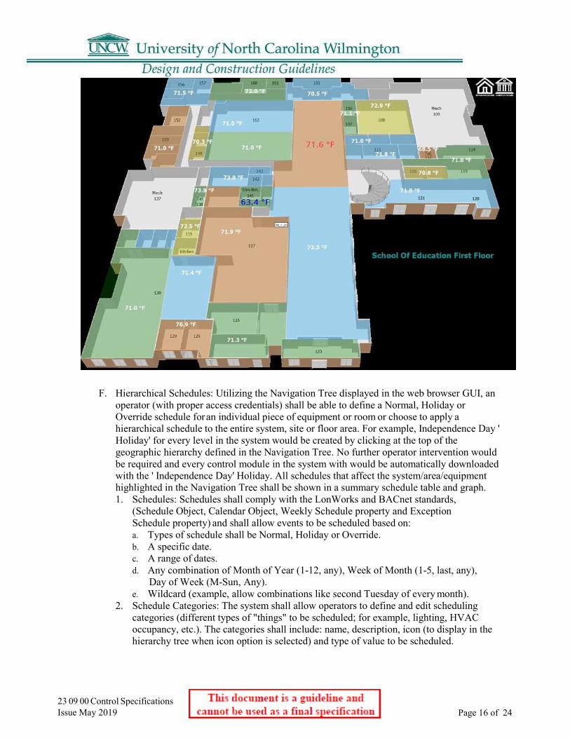
23 09 00 Control Specifications Issue May 2019 Page 16 of 24
F. Hierarchical Schedules: Utilizing the Navigation Tree displayed in the web browser GUI, anoperator (with proper access credentials) shall be able to define a Normal, Holiday orOverride schedule for an individual piece of equipment or room or choose to apply ahierarchical schedule to the entire system, site or floor area. For example, Independence Day 'Holiday' for every level in the system would be created by clicking at the top of thegeographic hierarchy defined in the Navigation Tree. No further operator intervention wouldbe required and every control module in the system with would be automatically downloadedwith the ' Independence Day' Holiday. All schedules that affect the system/area/equipmenthighlighted in the Navigation Tree shall be shown in a summary schedule table and graph.1. Schedules: Schedules shall comply with the LonWorks and BACnet standards,
(Schedule Object, Calendar Object, Weekly Schedule property and ExceptionSchedule property) and shall allow events to be scheduled based on:a. Types of schedule shall be Normal, Holiday or Override.b. A specific date.c. A range of dates.d. Any combination of Month of Year (1-12, any), Week of Month (1-5, last, any),
Day of Week (M-Sun, Any).e. Wildcard (example, allow combinations like second Tuesday of every month).
2. Schedule Categories: The system shall allow operators to define and edit schedulingcategories (different types of "things" to be scheduled; for example, lighting, HVACoccupancy, etc.). The categories shall include: name, description, icon (to display in thehierarchy tree when icon option is selected) and type of value to be scheduled.

23 09 00 Control Specifications Issue May 2019 Page 17 of 24
3. Schedule Groups: In addition to hierarchical scheduling, operators shall be able to definefunctional Schedule Groups, comprised of an arbitrary group of areas/rooms/equipmentscattered throughout the facility and site. For example, the operator shall be able todefine an ' individual tenant' group - who may occupy different areas within a buildingor buildings. Schedules applied to the ' tenant group' shall automatically be downloadedto control modules affecting spaces occupied by the ' tenant group'.
4. Intelligent Scheduling: The control system shall be intelligent enough to automaticallyturn on any supporting equipment needed to control the environment in an occupiedspace. If the operator schedules an individual room in a VAV system for occupancy, forexample, the control logic shall automatically turn on the VAV air handling unit, chiller,boiler and/or any other equipment required to maintain the specified comfort andenvironmental conditions within the room.
5. Partial Day Exceptions: Schedule events shall be able to accommodate a time rangespecified by the operator (ex: board meeting from 6 pm to 9 pm overrides Normalschedule for conference room).
6. Schedule Summary Graph: The schedule summary graph shall clearly show Normalversus Holiday versus Override Schedules and the net operating schedule that resultsfrom all contributing schedules. Note: In case of priority conflict between schedules atthe different geographic hierarchy, the schedule for the more detailed geographic levelshall apply.
G. Alarms: Alarms associated with a specific system, area, or equipment selected in theNavigation Tree, shall be displayed in the Action Pane by selecting an ' Alarms' view. Alarms,and reporting actions shall have the following capabilities:1. Alarms View: Each Alarm shall display an Alarms Category (using a different icon for
each alarm category), date/time of occurrence, current status, alarm report and a boldURL link to the associated graphic for the selected system, area or equipment. The URLlink shall indicate the system location, address and other pertinent information. Anoperator shall easily be able to sort events, edit event templates and categories,acknowledge or force a return to normal in the Events View as specified in this section.
2. Alarm Categories: The operator shall be able to create, edit or delete alarm categoriessuch as HVAC, Maintenance, Fire, or Generator. An icon shall be associated with eachalarm category, enabling the operator to easily sort through multiple events displayed.
3. Alarm Templates: Alarm template shall define different types of alarms and theirassociated properties. As a minimum, properties shall include a reference name, verbosedescription, severity of alarm, acknowledgement requirements, and high/low limit and outof range information.
4. Alarm Areas: Alarm Areas enable an operator to assign specific Alarm Categories tospecific Alarm Reporting Actions. For example, it shall be possible for an operator toassign all HVAC Maintenance Alarm on the 1st floor of a building to email the technicianresponsible for maintenance. The Navigation Tree shall be used to setup Alarm Areas inthe Graphic Pane.
5. Alarm Time/Date Stamp: All events shall be generated at the DDC control module leveland comprise the Time/Date Stamp using the standalone control module time and date.
6. Alarm Configuration: Operators shall be able to define the type of Alarm generated perobject. A ' network' view of the Navigation Tree shall expose all objects and theirrespective Alarm Configuration. Configuration shall include assignment of Alarm, type ofAcknowledgement and notification for return to normal or fault status.
7. Alarm Summary Counter: The view of Alarm in the Graphic Pane shall provide a numericcounter, indicating how many Alarms are active (in alarm), require acknowledgement andtotal number of Alarms in the BAS Server database.
8. 8. Alarm Auto-Deletion: Alarms that are acknowledged and closed shall be auto-deletedfrom the database and archived to a text file after an operator defined period.

23 09 00 Control Specifications Issue May 2019 Page 18 of 24
9. Alarm Reporting Actions: Alarm Reporting Actions specified shall be automaticallylaunched (under certain conditions) after an Alarm is received by the BAS serversoftware. Operators shall be able to easily define these Reporting Actions using theNavigation Tree and Graphic Pane through the web browser GUI. Reporting Actionsshall be as follows:a. Print: Alarm information shall be printed to the BAS server's PC or a networked printer.b. Email: Email shall be sent via any POP3-compatible e-mail server (most Internet
Service Providers use POP3). Email messages may be copied to several email accounts.Note: Email reporting action shall also be used to support alphanumeric paging services,where email servers support pagers.
c. File Write: The ASCII File write reporting action shall enable the operator to appendoperator defined alarm information to any alarm through a text file. The alarminformation that is written to the file shall be completely definable by the operator. Theoperator may enter text or attach other data point information (such as AHU dischargetemperature and fan condition upon a high room temperature alarm).
d. Write Property: The write property reporting action updates a property value in ahardware module.
e. SNMP: The Simple Network Management Protocol (SNMP) reporting action sends anSNMP trap to a network in response to receiving an alarm.
f. Run External Program: The Run External Program reporting action launches specifiedprogram in response to an event.
H. Trends: As system is engineered, all points shall be enabled to trend. Trends shall both bedisplayed and user configurable through the Web Browser GUI. Trends shall comprise analog,digital or calculated points simultaneously. A trend log's properties shall be editable using theNavigation Tree and Graphic Pane.1. Viewing Trends: The operator shall have the ability to view trends by using the
Navigation Tree and selecting a Trends button in the Graphic Pane. The system shallallow y- and x-axis maximum ranges to be specified and shall be able tosimultaneously graphically display multiple trends per graph.
2. Local Trends: Trend data shall be collected locally by Multi-Equipment/SingleEquipment general-purpose controllers, and periodically uploaded to the BAS server ifhistorical trending is enabled for the object. Trend data, including run time hours andstart time date shall be retained in non-volatile module memory. Systems that rely on agateway/router to run trends are NOT acceptable.
3. Resolution. Sample intervals shall be as small as one second. Each trended point willhave the ability to be trended at a different trend interval. When multiple points areselected for displays that have different trend intervals, the system will automaticallyscale the axis.
4. Dynamic Update. Trends shall be able to dynamically update at operator-definedintervals.
5. Zoom/Pan. It shall be possible to zoom-in on a particular section of a trend for moredetailed examination and ' pan through' historical data by simply scrolling the mouse.
6. Numeric Value Display. It shall be possible to pick any sample on a trend and have thenumerical value displayed.
7. Copy/Paste. The operator shall have the ability to pan through a historical trend andcopy the data viewed to the clipboard using standard keystrokes (i.e. CTRL+C,CTRL+V).
I. Security Access: Systems that Security access from the web browser GUI to BAS servershall require a Login Name and Strong Password. Access to different areas of the BAS systemshall be defined in terms of Role-Based Access Control privileges as specified:

23 09 00 Control Specifications Issue May 2019 Page 19 of 24
b. Edit Privileges shall comprise: Set point, Tuning and Logic, Manual Override, andPoint Assignment Parameters.
c. Function Privileges shall comprise: Alarm/Event Acknowledgement, ControlModule Memory Download, Upload, Schedules, Schedule Groups, ManualCommands, Print and Alarm/Event Maintenance.
2. Geographic Assignment of Roles: Roles shall be geographically assigned using a similarexpandable/collapsible navigation tree. For example, it shall be possible to assign twoHVAC Technicians with similar competencies (and the same operator defined HVACRole) to different areas of the system.
2.09 Graphical Programming A. The system software shall include a Graphic Programming Language (GPL) for all DDC
control algorithms resident in all control modules. Any system that does not use a drag anddrop method of graphical icon programming shall not be accepted. All systems shall use aGPL method used to create a sequence of operations by assembling graphic microblocks thatrepresent each of the commands or functions necessary to complete a control sequence.Microblocks represent common logical control devices used in conventional control systems,such as relays, switches, high signal selectors etc., in addition to the more complex DDC andenergy management strategies such as PID loops and optimum start. Each microblock shallbe interactive and contain the programming necessary to execute the function of the device itrepresents.
B. Graphic programming shall be performed while on screen and using a mouse; eachmicroblock shall be selected from a microblock library and assembled with other microblocksnecessary to complete the specified sequence. Microblocks are then interconnected on screenusing graphic "wires," each forming a logical connection. Once assembled, each logicalgrouping of microblocks and their interconnecting wires then forms a graphic function blockwhich may be used to control any piece of equipment with a similar point configuration andsequence of operation.
C. Graphic Sequence: The clarity of the graphic sequence shall be such that the operator has theability to verify that system programming meets the specifications, without having to learn orinterpret a manufacturer's unique programming language. The graphic programming shall beself-documenting and provide the operator with an understandable and exact representation ofeach sequence of operation.
D. GPL Capabilities: The following is a minimum definition of the capabilities of the GraphicProgramming software:1. Function Block (FB): Shall be a collection of points, microblocks and wires which have
been connected together for the specific purpose of controlling a piece of HVACequipment or a single mechanical system.
2. Logical I/O: Input/Output points shall interface with the control modules in order to readvarious signals and/or values or to transmit signal or values to controlled devices.
3. Microblocks: Shall be software devices that are represented graphically and may beconnected together to perform a specified sequence. A library of microblocks shall besubmitted with the control contractors bid.
4. Wires: Shall be Graphical elements used to form logical connections between microblocksand between logical I/O.
5. Reference Labels: Labels shall be similar to wires in that they are used to form logicalconnections between two points. Labels shall form a connection by reference instead of avisual connection, i.e. two points labeled 'A' on a drawing are logically connected eventhough there is no wire between them.
1. Roles: Roles shall reflect the actual roles of different types of operators. Each roleshall comprise a set of ' easily understood English language' privileges. Roles shall bedefined in terms of View, Edit and Function Privileges.
View Privileges shall comprise: Navigation, Network, and Configuration Trees, Operators, Roles and Privileges, Alarm/Event Template and Reporting Action.
a.

23 09 00 Control Specifications Issue May 2019
Page 20 of 24
6. Parameter: A parameter shall be a value that may be tied to the input of a microblock.7. Properties: Dialog boxes shall appear after a microblock has been inserted which has
editable parameters associated with it. Default parameter dialog boxes shall containvarious editable and non-editable fields and shall contain 'push buttons' for the purposeof selecting default parameter settings.
8. Icon: An icon shall be graphic representation of a software program. Each graphicmicroblock has an icon associated with it that graphically describes its function.
9. Menu-bar Icon: Shall be an icon that is displayed on the menu bar on the GPL screen,which represents its associated graphic microblock.
10. Live Graphical Programs: The Graphic Programming software shall support a ' live'mode, where all input/output data, calculated data and set points shall be displayed in a 'live' real- time mode.
2.10 Web Browser Graphical User Interface
A. Color Graphics: The Web Browser GUI shall make extensive use of color in the graphicpane to communicate information related to set points and comfort. Animated .gifs or .jpg,vector scalable, active set point graphic controls shall be used to enhance usability.Graphics tools used to create Web Browser graphics shall be non-proprietary and conformto the following basic criteria:1. Display Size: The GUI workstation software shall graphically display in a minimum
of 1024 by 768 pixels 24 bit True Color.2. General Graphic: General area maps shall show locations of controlled buildings in
relation to local landmarks.3. Color Floor Plans: Floor plan graphics shall be multi-colored to differentiate between
the different zones and areas. Colors selected are based on a neutral palette as to notshow a large variance in bright colors but more of a neutral, slightly different tones.Provide a visual display of temperature relative to their respective set points via theuse of a color changing font and size that displays the zone temperature. Thedisplayed temperature shall change to a red blinking, size 20 font for high spacetemperature and blue blinking, size 20 font for low space temperature. The colors andfont size shall be updated as a zone's actual comfort condition changes from a normalrange to a high or low out of range measurement.
4. General Graphic: A general first page for the building shall be of a standard summaryformat showing vital information and links to the buildings operation and status. ThisPX page is named “overview” and is the first page to go to when accessing thebuilding from the N4 Campus homepage.

23 09 00 Control Specifications Issue May 2019 Page 21 of 24

23 09 00 Control Specifications Issue May 2019
Page 22 of 24
2.11 Lonworks Network Management A. Systems requiring the use of third-party LonWorks network management tools shall not be
accepted.B. Network management shall include the following services: device identification, device
installation, device configuration, device diagnostics, device maintenance and networkvariable binding.
C. The Network configuration tool shall also provide diagnostics to identify devices on thenetwork, to reset devices and to view health and status counters within devices.
D. These tools shall provide the ability to "learn" an existing LonWorks network, regardless ofwhat network management tool(s) were used to install the existing network, so that existingLonWorks devices and newly added devices are part of a single network managementdatabase.
E. The network management database shall be resident in the Site Network Controller(SNC), ensuring that anyone with proper authorization has access to the networkmanagement database at all times. Systems employing network management databasesthat are not resident, at all times and within the control system shall not be accepted.
F. Color Graphics: The Web Browser GUI shall make extensive use of color in the graphicpane to communicate information related to set points and comfort. Animated .gifs or .jpg,vector scalable, active set point graphic controls shall be used to enhance usability.Graphics tools used to create Web Browser graphics shall be non-proprietary and conformto the following basic criteria:1. Display Size: The GUI workstation software shall graphically display in a minimum of
1024 by 768 pixels 24 bit True Color.2. General Graphic: A general first page for the building shall be of a standard summary
format showing vital information and links to the buildings operation and status. ThisPX page is named “overview” and is the first page to go to when accessing thebuilding from the N4 Campus homepage.
Part 3 Execution 3.01 Examination
A. Do not begin installation until substrates have been properly prepared.B. If substrate preparation is the responsibility of another installer, notify Architect of
unsatisfactory preparation before proceeding.3.02 Preparation
A. Clean surfaces thoroughly prior to installation.
B. Prepare surfaces using the methods recommended by the manufacturer for achieving thebest result for the substrate under the project conditions.
3.03 General
A. Install system and materials in accordance with manufacturer's instructions, and asdetailed on the project drawing set.
B. Line and low voltage electrical connections to control equipment shown specified orshown on the control diagrams shall be furnished and installed by the Control SystemContractor in accordance with these specifications.
C. Equipment furnished by the Mechanical Contractor that is normally wired beforeinstallation shall be furnished completely wired. Control wiring normally performed inthe field will be furnished and installed by the Control System Contractor.
D. All control devices mounted on the face of control panels shall be clearly identified as tofunction and system served with permanently engraved phenolic labels.

23 09 00 Control Specifications Issue May 2019
Page 23 of 24
3.04 Wiring A. All electrical control wiring to the control panels shall be the responsibility of the Control
System Contractor.B. All wiring shall be in accordance with the Project Electrical Specifications (Division 16), the
National Electrical Code and any applicable local codes. All control wiring shall beinstalled in raceways.
C. Excess wire shall not be looped or coiled in the controller cabinet.D. Incorporate electrical noise suppression techniques in relay control circuits.E. There shall be no drilling on the controller cabinet after the controls are mounted inside.F. Careful stripping of wire while inside the cabinet is required to ensure that no wire strand
fragments land on circuit boards.G. Use manufacturer-specified wire for all network connections.H. Use approved optical isolation and lightning protection when penetrating building
envelope.I. Read installation instructions carefully. Any unavoidable deviations shall be approved by
owner's rep prior to installation.3.05 Acceptance Testing
A. Upon completion of the installation, the Control System Contractor shall load all systemsoftware and start-up the system. The Control System Contractor shall perform all necessarycalibration, testing and de-bugging and perform all required operational checks to insurethat the system is functioning in full accordance with these specifications.
B. The Control System Contractor shall perform tests to verify proper performance ofcomponents, routines and points. Repeat tests until proper performance results. This testingshall include a point- by-point log to validate 100% of the input and output points of theDDC system operation.
C. System Acceptance: Satisfactory completion is when the Control System Contractor hasperformed successfully all the required testing to show performance compliance with therequirements of the Contract Documents to the satisfaction of the Owner's Representative.System acceptance shall be contingent upon completion and review of all correcteddeficiencies.
3.06 Operator Training A. During system commissioning and at such time acceptable performance of the Control
System hardware and software has been established, the Control System Contractor shallprovide on-site operator instruction to the owner's operating personnel. Operator instructionshall be done during normal working hours and shall be performed by a competentrepresentative familiar with the system hardware, software and accessories.
B. The Control System Contractor shall provide 48 total hours of comprehensive training inmultiple sessions for system orientation, product maintenance and troubleshooting,programming and engineering. These classes are to be spread out during the 1st yearwarranty period. The first class starting after final commissioning and the last class is to bein the last month of 1-year warranty period.

23 09 00 Control Specifications Issue May 2019 Page 24 of 24
3.07 Warranty Period Services A. Equipment, materials and workmanship incorporated into the work shall be warranted for a
period of one year from the time of system acceptance.B. Within this period, upon notice by the Owner, any defects in the BMS due to faulty materials,
methods of installation or workmanship shall be promptly repaired or replaced by the ControlSystem Contractor at no expense to the Owner.
C. Maintenance of Computer Software Programs: The Control System Contractor shall maintainall software during the standard first year warranty period. In addition, all factory or sub-vendor upgrades to software during the first year warranty period shall be added to thesystems, when they become available, at no additional cost. In addition to first year standardwarranty, software provided by Control System Contractor shall come with a 1 Year SoftwareMaintenance license. All SNC and BAS Servers are included in this coverage.
D. Maintenance of Control Hardware: The Control System Contractor shall inspect, repair,replace, adjust, and calibrate, as required, the controllers, control devices and associatedperipheral units during the warranty period. The Control System Contractor shall then furnisha report describing the status of the equipment, problem areas (if any) noticed during servicework, and description of the corrective actions taken. The report shall clearly certify that allhardware is functioning correctly.
E. Service Period: Calls for service by the Owner shall be honored within 24 hours and are notto be considered as part of routine maintenance.
F. Service Documentation: A copy of the service report associated with each owner-initiatedservice call shall be provided to the owner.
3.08 Warranty Access A. The Owner shall grant to the Control System Contractor reasonable access to the BMS
during the warranty period. Remote access to the BMS (for the purpose of diagnostics andtroubleshooting, via the Internet, during the warranty period) will be allowed.
3.09 Operation & Maintenance Manuals A. See Division 1 for requirements. O&M manuals shall include the following elements, as a minimum:
1. As-built control drawings for all equipment.2. As-built Network Communications Diagram.3. General description and specifications for all components.4. Completed Performance Verification sheets.5. Completed Controller Checkout/Calibration Sheets.
3.10 Protection A. Protect installed products until completion of project.B. Touch-up, repair or replace damaged products before Substantial Completion.

This document is a guideline and cannot be used as a final specification
23 09 93 Sequence of Operation for HVAC Controls
1.01 General A. Sequence of Operations for all systems and equipment must be put on document drawings.
23 09 93 Sequence of Operation for HVAC Controls Issue May 2019
Page 1 of 1
This document is a guideline and cannot be used as a final specification
23 11 23 Facility Natural-Gas Piping
1.01 General A. All boiler gas trains shall be OSHA and FM compliant.B. Flue outlets and gas vents must be shown on drawings and located to avoid any noise, odor,
or re-entrainment issues.C. All-natural gas piping for boilers shall have gauges located on the supply gas line
before and after the gas regulator and before entering the burner.D. All boiler gas piping shall have ¼ inch test ports before and after the regulator and at the
burner.
23 11 23 Facility Natural-Gas Piping Issue May 2019 Page 1 of 1

This document is a guideline and cannot be used as a final specification
23 21 13 Hydronic Piping
1.01 General A. Thermally fused PP-R or PP-RCT is the standard piping for building heating and cooling.
Acceptable Manufacturers are Aquatherm blue pipe, ISCO PP-RCT or approved equal.Chilled water piping may allow for HDPE piping with approval.
B. All underground non-metallic piping regardless of use shall have tracer wire.C. Air and dirt separation is required on all hydronic systems. Separators shall be the Spirovent
Dirt, the Taco series 4900-AD, the Caleffi DISCALDIRT series, or the Minikin EMFLEXModel SMAD. These separators remove air through coalescence and dirt through mediumimpingement. These single units replace a separate air separator and dirt removal system
23 21 13 Hydronic Piping Issue May 2019 Page 1 of 1

23 21 23 Hydronic Pumps Issue May 2019
This document is a guideline and cannot be used as a final specification
Page 1 of 1
23 21 23 Hydronic Pumps
1.01 General
A. All pumps shall be inline split coupled pumps. All pumps (condenser, chill water, hot water,primary, secondary, or loop pumps) shall have adequate clearances to service them. All pumpsshall have a shut off valve on both the suction and discharge lines within three feet of the pump.All pumps shall have thermometers mounted in a dry well on the suction and discharge lineswithin three feet of the pump. All electrical disconnects for the pumps shall be clearly markedas to the pump, which they service. All pumps will be clearly marked as to their function, e.g.chill water, hot water, etc. All piping to pumps shall be clearly marked as to the direction offlow and function. All variable frequency drives that control pumps shall be clearly marked asto the pumps they control and be equipped with a manual bypass for use in the event of theirfailure. All primary loop and secondary loop piping shall be clearly marked as such. Eachpump shall have a common pressure gauge valved to measure suction and discharge pressures.
B. Maximum pump speeds shall not exceed 1760 rpm.C. Pumps: UNCW standard is split coupled vertical inline pump. Manufacturer: Bell and Gosset,
Taco, Armstrong or approved equal.

23 23 00 Refrigerant Piping Issue May 2019
This document is a guideline and cannot be used as a final specification
Page 1 of 1
23 23 00 Refrigerant Piping
1.01 Refrigerant Monitoring A. All chillers shall be provided with a refrigerant reclaim machine capable of reclaiming
the type and amount of refrigerant contained in the respective chiller.

23 25 00 HVAC Water Treatment Issue May 2019
This document is a guideline and cannot be used as a final specification
Page 1 of 1
23 25 00 HVAC Water Treatment
1.01 General A. Unless connected to a centralized system, all new buildings shall include chemical treatment
programs for applicable equipment (boilers, cooling towers, chill water loops) for a period of oneyear. Said program to include all required chemicals necessary to maintain proper chemicallevels to prevent corrosion and mildew, and instruction for operating personnel. Chemical forthese programs will be provided in five-gallon containers, premixed. Dry powders are notacceptable. The chemical company will ensure that the equipment supplied for the program isinstalled in a neat and professional manner.
B. The chemical company representative shall make a visit every two weeks to the UNCW and checkin with the UNCW HVAC supervisor (or his/her representative). At the time of the visit watersamples will be taken the representative will coordinate with the UNCW representative to ensurethat the equipment is being properly utilized.

23 31 13 Metal Ducts Issue May 2019
This document is a guideline and cannot be used as a final specification
Page 1 of 1
23 31 13 Metal Ducts
1.01 General A. No insulation will be used inside ducts.B. Seal all duct, with the exception of transfer ducts, in accordance with SMACNA seal class
"A"; all seams, joints, and penetrations shall be sealed.C. Metal ducts shall be used in all areas. Flexible ducts used to connect to diffusers shall not
exceed 8’ in .
23 31 19 HVAC Casings Issue May 2019
This document is a guideline and cannot be used as a final specification
Page 1 of 1
23 31 19 HVAC Casings
1.01 General A. To be double walled with no exposed internal insulation.
This document is a guideline and cannot be used as a final specification
23 36 00 Air Terminal Units
1.01 General A. Fan Powered boxes are not permitted.B. All VAV boxes shall have two access doors, one on each side of the heat coil for
coil cleaning.C. All VAV units located above the ceiling shall have their location marked on the ceiling
grid directly below the unit.D. Variable air volume boxes shall be of double wall construction.E. All VAV units will have temperature sensors downstream of the heating coil.
23 36 00 Air Terminal Units Issue May 2019
Page 1 of 1

This document is a guideline and cannot be used as a final specification
23 37 13 Diffusers, Registers and Grilles
1.01 General A. Perforated supply air diffusers are not acceptable. Standard supply air diffuser is square cone
type.B. Per project requirements.
23 37 13 Diffusers, Registers & Grilles Issue May 2019 Page 1 of 1

This document is a guideline and cannot be used as a final specification
23 41 33 High-Efficiency Particulate Filtration 1.01 General
A. Differential pressure sensors and gauges are required before and after each set of filters.B. 2-inch prefilter, 6-inch box filter on small unitary AHUs.C. 2-inch prefilter, 24-inch box filter on larger building AHUs
23 41 33 High-Efficiency Particulate Filtration Issue May 2019
Page 1 of 1
23 52 16 Condensing Boilers Issue May 2019
This document is a guideline and cannot be used as a final specification
Page 1 of 1
23 52 16 Condensing Boilers
1.01 General A. For 2,000 MBH boilers and above, the preferred set of three boilers for the base bid are:
1. Fulton Endura, Endura+, or Vantage2. Viessman; Vitocrossal / Vertomat
B. For 2,000 MBH boilers, the University has add/alternate for Fulton condensing boilers modelBenchmark 2.0 (BMK-2.).
C. For 1,000 MBH boilers, the University has an add alternate for Fulton Endura.D. For less than 1,000 MBH boilers, the University has an add alternate for Fulton Endura.E. Boilers shall be provided with factory sound attenuators on intake and exhaust.F. Multiple boiler installations shall be provided with manufacturers’ Boiler Manager.
Boiler Manager shall communicate with Building Management System (BMS) viaModbus.
23 63 13 Air-Cooled Condensers Issue May 2019
This document is a guideline and cannot be used as a final specification Page 1 of 1
23 63 13 Air-Cooled Condensers
1.01 General A. The refrigerant coils/fins of all air-cooled equipment shall be supplied with a
salt water resistant coating applied at the factory.

23 64 16 Centrifugal Water Chillers Issue May 2019
This document is a guideline and cannot be used as a final specification Page 1 of 1
23 64 16 Centrifugal Water Chillers
1.01 General A. All chillers shall be supplied with a five-year warranty extended warranty covering all
parts and labor.B. There shall be an add alternate for a chiller with Turbocor compressors.
23 64 19 Reciprocating Water Chillers Issue May 2019
This document is a guideline and cannot be used as a final specification Page 1 of 1
23 64 19 Reciprocating Water Chillers
1.01 General A. All chillers shall be supplied with a five-year warranty extended warranty covering all
parts and labor.

23 65 00 Cooling Towers Issue May 2019
This document is a guideline and cannot be used as a final specification Page 1 of 1
23 65 00 Cooling Towers
1.01 Preferred Vendor A. University preferred cooling tower is the Tower Tech : www.towertechinc.com
23 73 13 Modular Indoor Central-Station Air Handling UnitsIssue May 2019
This document is a guideline and cannot be used as a final specification Page 1 of 1
23 73 13 Modular Indoor Central-Station Air Handling Units
1.01 General A. Units shall be double wall construction with no exposed insulation.B. Cooling Coil Section inner wall shall be stainless steel.C. Central air handling units shall have airside enthalpy economizer capability.D. Fans shall have appropriate isolation pads or vibration isolators to suppress
vibration transmission.E. Draw through units shall be equipped with Costgard condensate control devices.F. If return fans are required, they shall be internal to the AHU and shall have access doors for
shafts and bearings.G. All air handling units shall be set in a metal pan with a drain to the floor drain. Float
switches shall not be permitted.H. Fan Wall Systems – Systems shall consist of direct drive fans, minimum four (4) fans.
Preferred manufacturer/system:1. Climate Craft; Fan Matrix2. CES Group; FanWall System3. Trane; Fan Array
I. All dampers shall be TAMCO Series 9000 SW.J. Utilize campus loop chilled water and hot water when possible.K. Utilize Trent Technologies condensate drain instead of liquid traps.

This document is a guideline and cannot be used as a final specification
23 74 33 Dedicated Outdoor-Air Units
1.01 General A. Construction to be the same as in section 23 73 13.B. Utilize campus loop chilled water and hot water when possible.C. Utilize Trent Technologies condensate drain instead of liquid traps.
23 74 33 Dedicated Outdoor-Air Units Issue May 2019 Page 1 of 1

This document is a guideline and cannot be used as a final specification
23 81 26 Split System Air-Conditioners
1.01 General A. Condensers for heat pumps and DX units shall be mounted on a level and stable concrete
pad and in areas accessible to traffic protected by bollards.B. Condensers shall be equipped with a liquid line filter dryer.C. Lines shall be run in a neat and orderly manner with no contact between lines. All
refrigerant lines shall be strapped to a section of Unistrut that is anchored to the concretepad.
D. The refrigerant coils/fins of all air-cooled equipment shall be supplied with a salt waterresistant coating applied at the factory.
E. Utilize Trent Technologies condensate drain instead of liquid traps or approved equal.
23 81 26 Split System Air-Conditioners Issue May 2019 Page 1 of 1
This document is a guideline and cannot be used as a final specification
23 82 16 Air Coils
1.01 General A. All cooling/heating coils especially in duct work are to have access doors.B. Cooling coil casing, bracketing, and drain pans shall be stainless steel.C. Maximum cooling coil face velocity shall be 400 feet per minute.D. Chilled water-cooling coils shall have minimum tube velocity of 4 feet per second at the
maximum flow rate.
23 82 16 Air Coils Issue May 2019 Page 1 of 1

23 82 19 Fan Coil Units Issue May 2019
This document is a guideline and cannot be used as a final specification Page 1 of 1
23 82 19 Fan Coil Units
1.01 General A. The installation of fan coil units is typically prohibited and allowed only by permission of
the University under certain circumstances.
23 82 23 Unit Ventilators Issue May 2019
This document is a guideline and cannot be used as a final specification Page 1 of 1
23 82 23 Unit Ventilators
1.01 General A. Rooftop equipment such as powered ventilation units shall be accessible via a roof
hatch from the floor below.B. When powered ventilators are thermostatically controlled, the thermostat control shall be at a
level that is accessible without the use of a ladder.C. Powered ventilators shall have an on/off switch at the roof vent.

This document is a guideline and cannot be used as a final specification
23 82 39 Unit Heaters
1.01 Cabinet Type A. The installation of cabinet unit heaters is typically prohibited and allowed only by
permission of the University under certain circumstances (for example stairwellconditioning).
23 82 39 Unit Heaters Issue May 2019 Page 1 of 1
26 01 00 Electrical General Issue May 2019
This document is a guideline and cannot be used as a final specification
Page 1 of 1
26 01 00 Electrical General
1.01 State of North Carolina-, Dept. of Administration, State Construction Office-” Electrical Guidelines and Policies” is to be used in conjunction with these UNCW Guidelines.
1.02 All electrical conductors shall be copper.
1.03 Meters shall be provided to indicate building electrical demand, see Section 26 24 16 for details
1.04 A copy of the electrical riser diagram shall be mounted near the main switchgear in the electrical room under clear protective material.
1.05 For any electric / electronic equipment proposed to be mounted on the exterior of a building, drawings showing details of such equipment shall be submitted to the University for review and approval prior to installation.
26 05 33 Conduit Issue May 2019
This document is a guideline and cannot be used as a final specification
Page 1 of 1
26 05 33 Conduit
1.01 All electrical distribution within buildings shall be installed in rigid, intermediate or EMT conduit utilizing all steel compression type fittings as connectors or couplings.
1.02 Underground raceways shall be either galvanized rigid steel or PVC duct encased in concrete; however, all ducts leaving a building shall be galvanized rigid steel for a minimum distance of five (5) feet from the building.
1.03 Red dye shall be applied to the top of freshly placed concrete in all underground high voltage (> 5KV) duct banks as a warning of electrical hazard in the event of future excavation. This is in addition to the required warning tape installed 6” below grade.
1.04 Ducts should be securely anchored during concrete placement to prevent movement. The required spacing between adjacent ducts shall be maintained with plastic spacers.
1.05 Joints in duct in a duct bank should always be staggered a minimum of 6”.
1.06 Conduit and fittings shall be concealed wherever possible especially in finished spaces and public areas. Conduit can be installed exposed in rooms like mechanical, storage etc. however they must be installed in a manner as to be protected from physical damage. Run exposed conduits neatly and as inconspicuously as practicable and install parallel or perpendicular to walls, structural members or intersections of vertical planes and ceilings. Right angle turns may be made with manufactured elbows for sizes of conduit 1-1/4 inches and larger.
1.07 Minimum size conduit for fire alarm system is ¾”
1.08 Acceptable Manufactures: Allied, Republic, Western Tube , Wheatland.

26 08 00 Electrical Testing Issue May 2019
This document is a guideline and cannot be used as a final specification Page 1 of 1
26 08 00 Electrical Testing
1.01 Testing on 600 volt rated equipment and cable to be done using a 1000-volt meggar. All new wire shall hold at least 100 meg ohms.
1.02 Medium voltage cable testing shall follow the manufacturer recommendations for new or installed cable, however the minimum test voltage shall be for new cable 5 times cable rating and for existing cable 3 times cable rating. Voltage in testing to increase in a 5000-volt increment and be held for 1 minutes at each voltage and for 10 minutes at the top voltage.Take and record readings at each stage as required. Caution must be used in dissipating the capacitive charge on the cable. Apply all grounds with caution and safety in mind.
This document is a guideline and cannot be used as a final specification
26 12 19 Pad Mounted Distribution Transformers
1.01 All molded elbow connectors installed on high voltage cables at switches and transformers shall be equipped with high voltage test points on the elbow connectors.
1.02 Acceptable Manufacturers: Copper and GE.
26 12 19 Pad Mounted Distribution Transformers Issue May 2019 Page 1 of 1

This document is a guideline and cannot be used as a final specification
26 18 00 Air Interrupter Switch
1.01 UNCW primary electrical system operates at a voltage of 12.47KV, wye connected. System is an underground radial feed to outdoor pad mounted transformers protected by a fused, pad mounted outdoor distribution switch centers. The distribution switch is an S&C Electric “Vista Underground Distribution “type and shall be bid as a preferred alternate when needed.
26 18 00 Air Interrupter Switch Issue May 2019 Page 1 of 1

This document is a guideline and cannot be used as a final specification
26 22 00 Dry Type Transformers
1.01 K-rated transformers should be used for non-linear loads. Transformers shall be Class- 80 degree rise and copper.
1.02 Acceptable Manufacturers: Heavy Duty, Square D, Siemens, GE, Eaton.
26 22 00 Dry Type Transformers Issue May 2019 Page 1 of 1

26 24 16 Panelboards Issue May 2019
This document is a guideline and cannot be used as a final specification Page 1 of 1
26 24 16 Panelboards
1.01 Panels A. All electrical panels are to be “industrial” / “commercial” grade. Specify the
following manufacturers only in base bid: Square “D”, General Electric, Eaton-CutlerHammer.
1.02 Metering A. A building meter shall be provided to monitor the electrical usage of the building.B. Main distribution panel shall be equipped with digital metering to measure:
1. Voltage – phase to phase and phase to neutral2. Amperage- all three phases3. KW, KVAR4. KW Demand5. Peak Demand6. Power factor7. Events Recording (minimum of 4 events)8. Meter shall be connected to the building automation system for monitoring
purposes1.03 Phase Protection
A. Provide electrical phase protection at main to prevent single phasing of service tothe building.
26 27 26 Wiring Devices Issue May 2019
This document is a guideline and cannot be used as a final specification Page 1 of 1
26 27 26 Wiring Devices
1.01 Receptacles A. Duplex electrical receptacles, 120-volt AC shall be provided in corridors at 25-foot intervals
for housekeeping use, also in stairwells and immediately adjacent to elevators. Providereceptacles near building entrances and around the exterior of the building for maintenanceuse.
B. Receptacles are to be installed in the vertical position with the ground terminal on top.C. Duplex electrical outlets should be provided in classrooms for lectern, ceiling
mounted projection equipment, slide projectors, and accessible to student seating.D. All chiller rooms shall be equipped with a welding machine electrical outlet.E. Red outlets will be installed for all generator powered devices
1.02 Acceptable Manufacturers: Leviton, Hubbell, Pass and Seymour/Legrand.
26 29 23 Variable Frequency Controllers Issue May 2019
This document is a guideline and cannot be used as a final specification
Page 1 of 1
26 29 23 Variable Frequency Controllers
1.01 Acceptable Manufacturers
A. Danfoss GrahamB. ABBC. Honeywell
1.02 Requirements
A. When VFD not supplied with mechanical equipment, it shall be supplied by the controlsvendor.

26 32 13 Packaged Engine Generators SystemsIssue May 2019
This document is a guideline and cannot be used as a final specification Page 1 of 1
26 32 13 Packaged Engine Generators Systems
1.01 Emergency generators shall be equipped with automatic transfer switches. Specify emergency generators as manufactured only by Caterpillar and shall be bid as a preferred alternate.
1.02 Where required by critical system, uninterrupted power supplies will be provided to appropriate portions of buildings.
1.03 Buildings without emergency generator backup should have the main switchboard incorporate a design with a double throw scheme that can allow for the connection of a portable emergency generator. Interlocking on this installation must be considered to prevent accidents.
1.04 Fuel tank for emergency generator shall be installed above ground and have double wall construction to provide secondary containment. Fuel tank to be sized to provide fuel for eight (8) hours of running at 100% load plus four (4) days running at 50% load.
26 51 00 Interior Luminaires Issue May 2019
This document is a guideline and cannot be used as a final specification
Page 1 of 1
26 51 00 Interior Luminaires (Includes Emergency Lighting)
1.01 Interior lighting fixtures shall be of the energy saving type.
1.02
1.03
1.04
1.05
1.06
Emergency lighting shall be mounted above an average person’s reach (7ft.min.)
Wall mounted lighting fixtures are preferred in stairwells rather than high ceiling mounted units for ease of cleaning and maintenance.
Interior and exterior light fixtures mounted at high elevations shall be required to have a means of access provided for maintenance equipment that includes exterior road access and adequate pavement/floor capacity to support equipment without damage.
Strong consideration shall be given to using emergency lighting inverters rather than individual battery packs on major renovations or new building projects. The use of battery packs will require specific approval from UNCW.
The University Standard is 2x4 LED. Consideration shall be given to indirect/direct fixtures for each project based on application. Designer shall obtain prior approval from the University for all fixtures.

26 56 00 Site & Exterior Lighting Issue May 2019
This document is a guideline and cannot be used as a final specification
Page 1 of 1
26 56 00 Site and Exterior Lighting
1.01
1.02 Color of poles shall be “Black”
1.03 Street and roadway lighting to be at 480-volt, sidewalk lighting to be 277 volt. All lamps are LED, 120 watt for roadway, and 60 watt for walkways.
1.04 Exterior street lighting circuits shall be 3 -phase, 5 wire, 60-amp, 480 volt. Extend complete circuit from the source to the last pole installed. Designer shall utilize alternate circuits for fixture connections (i.e. first fixture on AB, second fixture on BC, third fixture on CA etc. till last pole). Use a similar sequence for the 277-volt s i d e w a l k l i g h t i n g circuit.
1.05 Following are acceptable light level at UNCW:
Average Minimum Uniformity Ratio
Sidewalks/walkways 1.0 0.2 5:1 Parking Lots 3.6 0.9 4:1
Building Entryways 5.0 1.0 5:1 Streets 2.0 0.6 5:1
1.06 Street lighting pole shall be specified as follows- 20ft. tapered aluminum pole
1.07 Sidewalk lighting pole shall be specified as follows- 14 ft. tapered aluminum pole. See Section 26 00 00 Appendix for detail.
All exterior light poles shall have ground rods in each base and PVC conduit shall be installed between light poles without interruption in the conduit runs. Each base shall contain one spare conduit for future use embedded in the base. All outside lighting shall be installed with photocell control and “H-O-A” override switches at the lighting contactor. See Section 26 00 00 Appendix for exterior lighting details.
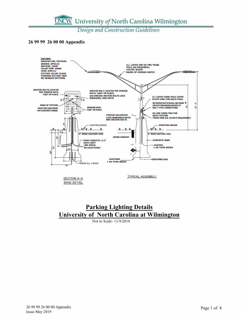
Page 1 of 826 99 99 26 00 00 Appendix Issue May 2019
Parking Lighting DetailsUniversity of North Carolina at Wilmington
Not to Scale- 11/9/2018
26 99 99 26 00 00 Appendix
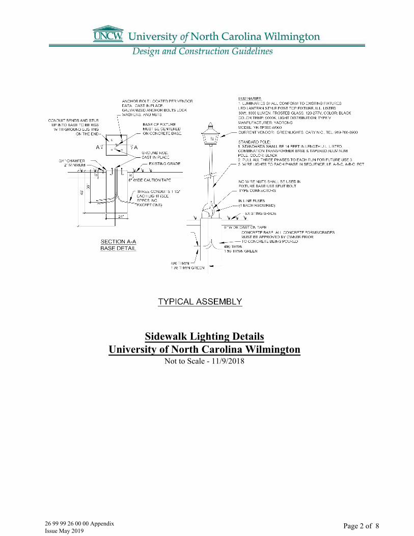
Page 2 of 8 26 99 99 26 00 00 Appendix Issue May 2019
Sidewalk Lighting DetailsUniversity of North Carolina Wilmington
Not to Scale - 11/9/2018

Page 3 of 826 99 99 26 00 00 Appendix Issue May 2019
Street Lighting DetailsUniversity of North Carolina Wilmington
Not to Scale- 11/9/2018

26 99 99 26 00 00 Appendix Issue May 2019
This document is a guideline and cannot be used as a final specification
Page 4 of 8
Main Campus: Pedestrian Pole Light

26 99 99 26 00 00 Appendix Issue May 2019
This document is a guideline and cannot be used as a final specification
Page 5 of 8
HAPCO Pole and Base
Main Campus: Street and Parking Lot Light Pole Assembly

26 99 99 26 00 00 Appendix Issue May 2019
This document is a guideline and cannot be used as a final specification
Page 6 of 8
Main Campus: Chancellors Walk Pole and Light

Page 7 of 8 26 99 99 26 00 00 Appendix Issue May 2019

Page 8 of 8 26 99 99 26 00 00 Appendix Issue May 2019
This document is a guideline and cannot be used as a final specification
27 00 00 Classroom Recommendations Issue May 2019 Page 1 of 1
27 00 00 ITSD’s Classroom Recommendations and Technology Baseline
The Project Manager should contact UNCW for an updated transmittal of the current ITSD ClassroomRecommendations & Technology Basline.

28 13 00 UNCW Access Control Issue May 2019
This document is a guideline and cannot be used as a final specification
Page 1 of 1
28 13 00 UNCW Standards for Installation of Access Control Equipment
The Project Manager should contact UNCW for an updated transmittal of the current Physical Security and Access standards.
28 16 00 UNCW Intrusion Systems Issue May 2019
This document is a guideline and cannot be used as a final specification
Page 1 of 1
28 16 00 UNCW Guidelines for the Installation of Intrusion/Burglary Systems
The Project Manager should contact UNCW for an updated transmittal of the current Physical Security and Access standards.

28 23 00 UNCW Camera Systems Issue May 2019
This document is a guideline and cannot be used as a final specification
Page 1 of 1
28 23 00 UNCW Standards for Installation of Cameras and Camera Systems
The Project Manager should contact UNCW for an updated transmittal of the current Physical Security and Access standards.

28 31 13 Fire & Security Alarm Systems Issue May 2019
This document is a guideline and cannot be used as a final specification
Page 1 of 4
28 31 13 Fire & Security Alarm Systems
Part 1: General Design Guidelines
1.01 All designs and system installations shall be in accordance with the latest version of the North Carolina State Construction Office “Fire Alarm Guidelines and Polices” document, NC State Construction Office “Electrical Guidelines and Policies” document, the most recent adopted version of relevant National Fire Protection Association (NFPA) Standards, and UNCW design & construction standards. Any deviations from these Guidelines and Standards must have written approval from the UNCW Architectural & Construction division, the UNCW Electrical Shop, and the UNCW Environmental Health & Safety Department. Designers/engineers shall closely monitor and thoroughly inspect the system design and installation to ensure compliance with these requirements. A. Renovations or modifications to existing buildings that alter the layout/design from the
original approved & accepted design shall require fire alarm redesign approved by NC Stateconstruction Office AHJ to accommodate changes to the building. All fire alarm systemalterations/modifications to accommodate building changes shall comply with all of thestandards in UNCW Part 1 1.01 General Design Guidelines.
B. Detailed and comprehensive specifications shall be prepared for all projects and shallinclude, but not limited to, specification manuals and detail drawings.
C. A pre-design meeting is required with the design engineer for all new fire alarm systems,system replacement/upgrades, or significantly altered fire alarm systems (addition/removal ofdevices).
D. A pre-construction meeting is required with the engineer, electrical contractor, fire alarmcontractor, UNCW project manager, and UNCW fire alarm technician for all new fire alarmsystems or major replacements/upgrades.
1.02 All fire alarm systems shall be of the addressable type, 24 vdc nominal operating voltage, and in compliance with NC State Construction Office requirements, NFPA Standards, and “UL” Listings.
1.03 All work on alarm systems will be done by workers experienced and qualified in the installation of alarm systems and shall be knowledgeable of the workings and installation requirements of the respective alarm system.
1.04 “NOTIFIER” brand fire alarm system control equipment and components are the campus standard and shall be specified and bid as preferred alternate on all projects. A. “System Sensor”, “Wheelock”, and “Gentex” are acceptable manufacturers of fire alarm
notification appliances. “System Sensor” brand is the campus standard and preferredmanufacturer for notification devices.
1.05 During the fire alarm “programming stage” consult with the system design engineer, UNCW lead fire alarm technician & UNCW Environmental Health & Safety to determine if alarm verification feature shall be turned on.
1.06 A password protected silent walk test feature shall be provided in the fire alarm system operation. As an alternate, a password protected means to bypass notification devices shall be provided in the fire alarm software programming to allow maintenance and testing while the building is occupied.

28 31 13 Fire & Security Alarm Systems Issue May 2019
This document is a guideline and cannot be used as a final specification
Page 2 of 4
This alternate method shall not require more than ten devices to be entered for bypassing notification in the building.
1.07 All contracts & project specifications pertaining to fire alarm and smoke detection systems shall include an “assurance of performance” clause. Nuisance alarms due to improper placement/application of devices or other repeat abnormalities causing issues within the system shall require corrective action by the engineers and/or installers to resolve the problem at no cost to UNCW. Corrective actions will require a retest of the system. Corrective actions can be up to and including full replacement of the system if necessary.
1.08 Security and Life Safety (fire alarm, panic, hold-up, environmental, etc.) communication dialers (DACT’s) shall be compatible with UNCW’s central alarm receiver and its current software version. Compatibility shall be confirmed with university personnel prior to any installation. Non-compatible items / systems shall be removed and replaced at the contractor’s expense. A. Acceptable alarm transmission formats are 3+1 standard or 4+2 standard. Contact ID is not
an acceptable transmission format.
1.09 “Ditek”, “Northern Technologies”, and “Emerson Network Power” are acceptable manufacturers of 24VDC and 120VAC surge protection on fire alarm system equipment and circuits, including phone lines on communication dialers. “DITEK” brand is the campus standard and is the preferred manufacturer for surge suppression/protection on fire alarm signal and notification circuits, fire alarm and security panel phone lines, and 120-volt AC electrical power supply.
1.10 All fire alarm wiring shall be installed in metal conduit. A. Minimum size of any conduit for fire alarm and security applications shall be ¾” trade size.B. All EMT conduit fittings shall be of all steel construction and of the compression type.C. Seal all raceway penetrations between conditioned and unconditioned environments
or extreme temperature differences to prevent condensation issues.D. Nonmetallic raceway is acceptable for below ground applications outside the building.
1.11 Splices (junctions) shall not be made in system wiring (except as specified inside terminal cabinets between floors of buildings). Fire alarm wiring for signaling, notification, and control shall be continuous without splice between devices, control panel boards, or terminal cabinets.
1.12 Terminal cabinets shall be minimum size of 10”x10”x4” and be accessible from standing floor level without the use of a ladder.
1.13 One copy of the fire alarm detection & initiating device installation shall be mounted beside the fire alarm control panel and each remote annunciator. This fire alarm installation wall chart shall indicate: (1) floor plan of each floor within the building; (2) location of all detection & initiating devices with their device address; (3) location of the fire alarm control panel, (4) all room numbers. A. Alterations to building floor plans shall require fire alarm charts to be replaced with
updated plans as part of the project that required the change to building floor plans. Handdrawn copies are not acceptable.
1.14 At the time of beneficial occupancy an electronic/digital copy (USB/flash drive) of the fire alarm drawings in a PDF format shall be provided to UNCW for use by maintenance personnel

28 31 13 Fire & Security Alarm Systems Issue May 2019
This document is a guideline and cannot be used as a final specification
Page 3 of 4
until complete final documentation is delivered at project closeout. These electronic drawings shall include system design drawings, construction as built wiring, system wiring details, wire termination numbers in all control panels, booster power supplies, terminal cabinets, and control / modules. This electronic copy of the drawings is in addition to any hardcopies required by the project specifications and standards.
1.15 Maintenance manuals in an electronic/digital format (USB/flash drive) shall be provided to UNCW at the time of beneficial occupancy and shall include installation, programming, and operation manuals, applicable cut sheets, technical information, and electronic circuit diagrams of all control panel layouts, modules, annunciators, communicators, power supplies, and all other components installed in the system. This electronic copy of the required maintenance manuals is in addition to any hardcopies required by the project specifications and standards.
1.16 In addition to spare parts required by the NC State Construction Office document “Fire Alarm Guidelines and Polices”, the project specification/guidelines shall require one of each type of fire alarm field component (excluding projected beam, air sampling devices) be supplied to UNCW at the time of beneficial occupancy (i.e. a minimum of one of each type notification device, module, control relay, detector, surge suppressor, etc.).
1.17 Smoke detectors shall not be installed in ceilings over the mid-point stairwell landings unless the ceiling height is 12 feet or less to the landing. For high ceiling areas use the Projected Beamtype smoke detection if detection is required in the stairwell. Smoke detectors shall not be mounted over stair steps. A. Notifier smoke detector model FAPT-851 multi criteria type and subsequent models are not allowed for use on new or renovation projects.
All device and pull boxes shall be securely mounted to the building. Device boxes installed in lay- in ceilings shall be supported in addition to the ceiling grid attachment. Monitor, relay, or control modules shall not be installed above ceilings. They shall be accessible from floor level without the use of ladders. A. Exception: Relays for damper control are permitted to be mounted into lay-in ceiling grid.
When it is possible and practical design fire alarm systems without the use of duct smoke detectors. The environment for this region make this type of detector highly susceptible to nuisance alarms and failures due to moisture issues. Where duct detectors must be used they shall be of the design that use a twist out, removable smoke detector.
1.21 The voltage shall be verified on each notification appliance circuit at the end of the line under full load on battery backup. The voltage will be measured after 5 minutes run time under full load and compared to allowable tolerances.
The fire alarm digital alarm communicating transmitter (DACT) shall be monitored by the fire alarm panel or shall be integral to the fire alarm panel CPU circuit board so that loss of telephone service will result in a trouble alarm on the fire alarm control panel. The trouble alarm resulting from problems with the DACT shall be capable of being silenced from the fire alarm control panel keypad. The fire alarm DACT shall be provided with two telephone lines for redundant dial out capability. When the DACT is not an integral part of the fire alarm control panel circuit board it shall be placed in a separate keyed enclosure adjacent to the fire alarm control panel. DACT’s which are not an integral component of the fire alarm CPU circuit board are not allowed to be installed inside the fire alarm control panel enclosure.
1.18
1.19
1.20
1.22

28 31 13 Fire & Security Alarm Systems Issue May 2019
This document is a guideline and cannot be used as a final specification
Page 4 of 4
1.23 Fire alarm control panels, booster power supplies, DACT, amplifier racks, terminal cabinets, and other similar enclosures shall not be used as raceways for cables or conductors that do not originate or terminate within the enclosure.
1.24 Cables or conductors from other systems cannot share fire alarm system raceway. This includes but is not limited to telephone cables, elevator recall conductors, AHU shutdown circuits, etc.
1.25 All fire alarm panel software access codes shall be provided to the lead UNCW Fire Alarm Technician at the completion of all projects.
1.26 The fire alarm control panel shall be capable of being programmed on site from the control panel keypad interface in addition to the use of a laptop computer connected to the control panel. The changing of EPROMS is not acceptable.
A. Fire alarm system equipment shall be fully serviceable by UNCW personnel. Proprietaryequipment with restricted access is not acceptable.
B. Smoke detectors or other addressable fire alarm system devices that are addressed by the firealarm control panel or the use of a hand-held programming device are not acceptable.
1.27 All equipment and components shall be installed according to the manufacturer’s listed instructions and all applicable codes and standards.
1.28 AHU shutdown during fire alarm shall be accomplished by addressable control relays controlled through the fire alarm control panel software. Utilizing smoke detector relay bases or the relay contacts on duct smoke detectors to achieve AHU shutdown is not allowed.
1.29 “Ademco” by Honeywell is the campus standard of intrusion/burglary panel hardware and shall be bid as preferred alternate on all projects requiring an intrusion/burglary system.
A. Any new intrusion/burglary system must be approved in writing by UNCW Police prior toinstallation. Consult with UNCW Police before planning any system installation.
B. Any approved intrusion/burglary system must be compatible with the central alarm receiverat UNCW Police department. Consult with UNCW Electrical Services alarm technicians toassist with determining system compatibility.
C. Wireless type sensors are prohibited for use at UNCW. Examples include but are notlimited to door contacts, motion sensors, beam detectors, panic buttons, and glass breaksensors. All installed sensors & accessories must be hardwired to the system control panel.

Page 1 of 1 31 31 16 Termite Control Issue May 2019
31 31 16 Termite Control
1.01 Coordination
A. Coordinate soil treatment application with excavating, filling, and grading and concretingoperations. Treat soil under footings, grade beams, and ground-supported slabs, beforeconstruction.
1.02 Warranty
A. Special Warranty: Written warranty, signed by applicator and Contractor certifying that termitecontrol work, consisting of applied soil termiticide treatment, will prevent infestation ofsubterranean termites. If subterranean termite activity or damage is discovered during warrantyperiod, re-treat soil and repair or replace damage caused by termite infestation.
1. Warranty Period: 15 years from date of final acceptance.
1.03 Maintenance Service
A. Continuing Service: Provide a proposal for a lifetime warranty, including monitoring, inspection,and retreatment for occurrences of termite activity, from applicator to Owner, in the form of acontinuing bond agreement, starting on the date of Owner Acceptance State services, obligations,conditions, and terms for agreement period and for future renewal options.
Part 2 - Products
2.01 Soil Treatment
A. Termiticide: Provide an EPA-registered non-repellent liquid termiticide, complying withrequirements of state and local authorities having jurisdiction.
1. Use only soil treatment solutions that are not harmful to plants.2. Use compatible dye in termiticide to provide visible evidence of treatment.3. Service Life of Treatment: Soil treatment termiticide that is effective for not less than 15 years
against infestation of subterranean termites.
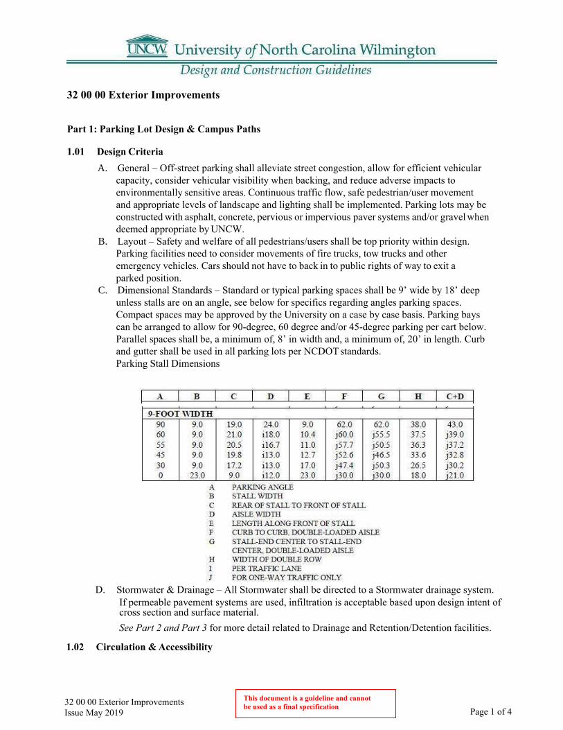
32 00 00 Exterior Improvements Issue May 2019 Page 1 of 4
This document is a guideline and cannot be used as a final specification
32 00 00 Exterior Improvements
Part 1: Parking Lot Design & Campus Paths
1.01 Design Criteria A. General – Off-street parking shall alleviate street congestion, allow for efficient vehicular
capacity, consider vehicular visibility when backing, and reduce adverse impacts to environmentally sensitive areas. Continuous traffic flow, safe pedestrian/user movement and appropriate levels of landscape and lighting shall be implemented. Parking lots may be constructed with asphalt, concrete, pervious or impervious paver systems and/or gravel when deemed appropriate by UNCW.
B. Layout – Safety and welfare of all pedestrians/users shall be top priority within design. Parking facilities need to consider movements of fire trucks, tow trucks and other emergency vehicles. Cars should not have to back in to public rights of way to exit a parked position.
C. Dimensional Standards – Standard or typical parking spaces shall be 9’ wide by 18’ deep unless stalls are on an angle, see below for specifics regarding angles parking spaces. Compact spaces may be approved by the University on a case by case basis. Parking bays can be arranged to allow for 90-degree, 60 degree and/or 45-degree parking per cart below. Parallel spaces shall be, a minimum of, 8’ in width and, a minimum of, 20’ in length. Curb and gutter shall be used in all parking lots per NCDOT standards.Parking Stall Dimensions
D. Stormwater & Drainage – All Stormwater shall be directed to a Stormwater drainage system.If permeable pavement systems are used, infiltration is acceptable based upon design intent ofcross section and surface material.See Part 2 and Part 3 for more detail related to Drainage and Retention/Detention facilities.
1.02 Circulation & Accessibility

32 00 00 Exterior Improvements Issue May 2019 Page 2 of 4
This document is a guideline and cannot be used as a final specification
A. Layout & Routing – Consideration to all pedestrian movements shall be considered, howeverrouting shall focus on main entries and exits. Promoting and reinforcing paths of travel mustbe integrated into the design to minimize maintenance and wear of landscaped areas. Oneaccessible route from parking to facility or facilities the lot is serving must be achieved.
B. Sidewalks, Ramps & Handrails – See section 32 00 00, 1.08 for more detail related topedestrian paths. Accessible sidewalks and ramps shall never exceed 1:12 in the direction oftravel. Cross slopes on all sidewalks and ramps shall never exceed 2%. Ramps must beprovided at curbs or other raised barriers to provide access to the accessible routes leadingfrom the parking lots. Widths must meet ADA Guidelines at time design is being completed.Handrails must conform to the latest requirements within the ADA Guidelines.
C. Accessible Space Design & Location – Spaces for disabled persons must conform to themost current ADA Guidelines at time of parking lot design. Soft or loose surfaces are notappropriate for accessible spaces or routes.
D. Bus Stops – Coordination with UNCW Planning, Facilities and Transportation shall occur inregard to existing, proposed and/or potential on-site covered bus stops. Safe connections toand from parking facilities shall be provided.
1.03 Pavement Striping and Marking A. Layout –All paved parking lots shall delineate spaces with markings. Traffic lanes,
circulation aisles, parking zones, special spaces and other features may be required.Markings shall be in accordance with the Manual of Uniform Traffic Control Devices or asotherwise approved by UNCW. Markings and signs shall be kept well maintained and inserviceable condition.
B. Signage – Handicapped, emergency vehicle, restrictions/requirements and/or anyother UNCW directives shall be posted visible to all and easily understood.
C. Painting & Marking – See section 32 12 16 Asphalt Paving for more detail. Pavementmarking at driveway locations for high traffic generators shall be thermoplastic. Otherrequired markings may be either thermoplastic or approved traffic paint with approval fromUNCW. Markings shall not be applied until pavement has been allowed to cure sufficientlyto allow volatiles to escape. Any faded, peeled or damaged markings due to early applicationshall be reinstalled at no cost to UNCW. All parking stall paintings shall be white.
D. Materials & Details – All materials and details shall be in accordancewith NCDOT standards.
1.04 Barriers & Barricades A. Wheel stops –Wheel stops shall be required 3’ from the end of stall when using 18’ deep
stalls. Curbing, crossties, and other acceptable material UNCW may be used and must be anchored into the ground.
B. Gates – Used to restrict use of parking to individuals with pre-approved permission. Gates may be two-way gate systems or a single gate with controlled egress. The preferred alternative is the MHTM Microdrive Magnetic Access Barrier with HID iCLASS R90 card reader.
C. Bollards – See Section 12 93 00, 1.05/1.06 for more detail related to bollard specifics.
1.05 Landscaping A. General – Parking lot landscaping is intended to minimize visual impact of vast expanses
of vehicular areas from public or private streets while reducing heat island effects. Designof lots shall break mass of spaces using planted islands (end cap and median betweenbays). Plant locations and arrangement shall always consider user safety, security, andpedestrian circulation and visibility. Leaves, fruit and other litter possible from plantmaterial shall be

32 00 00 Exterior Improvements Issue May 2019 Page 3 of 4
This document is a guideline and cannot be used as a final specification
considered to minimize maintenance and damage/impact to adjacent hardscape surfaces and buildings. All plant material specifications are to meet the American Standard for Nursery Stock. See section 32 90 00 Landscaping Design Guidelines for more detail related to plant, mulch, turf, installation and maintenance requirements
B. Tree & Shade Requirements – One tree per every 10 parking spaces is required unless otherwise approved by UNCW. Trees shall be located, at minimum, 15’ from light poles.
C. Island & Perimeter Landscape – A landscaped island must be provided every 12 parking spaces unless otherwise approved by UNCW. Interior islands must be 8’ in width, minimum, from back of curb to back of curb. Rows of parking must terminate with an island where a tree, light pole, fire hydrant or other utility structure may be located. No more than 48 spaces in a row can be accepted without an aisle for ease of vehicular circulation. Median islands shall be, a minimum, of 6’ in width unless a sidewalk is provided the overall width shall be, a minimum, of 12’. Perimeter islands must be, a minimum, of 6’ in width and shall be provided along internal access drives and adjacent streets. Perimeter landscape strips shall be, a minimum, of 6’ in width and planted at a rate of 30 shrubs per 100’ and 1 tree per 40’. Landscaped islands shall include provisions for water and electricity.See Section 32 90 00 Landscaping Design Guidelines for more detail related to plants, shrubs and turf.
1.06 Irrigation A. See Section 32 90 00, Part 8 of the Landscaping Design Guidelines for more detail.
1.07 Security & Lighting A. Emergency Call Stations – These shall be located conveniently and accessible as they are
intended to be used to call security of police during an emergency situation. The preferred alternate is the C24 Call Box.
B. Pathway Lighting – Shall always be provided for safety. Adequate foot candles shall be provided and confirmed by a photometric layout. All fixture and pole assemblies shall be black. See Section 26 56 00 for more detail related to lighting.
C. Parking Lot Lighting – Shall always be provided for safety. Adequate foot candles shall be provided and confirmed by a photometric layout. Light poles shall be located, at minimum, 15’ from tree locations. All fixture and pole assemblies shall be black.See Electrical specification 26 56 00 and Section 26 00 00 for more detail related to lighting and fixture assemblies.
D. Parking Access Control Gates- The preferred alternate is MHTM- Microdrive Magnetic Access Barrier
1.08 Pedestrian Paths A. Pedestrian paths shall be constructed of asphalt, concrete and/or concrete or brick pavers. If
pavers are used, appropriate paver ratings shall be installed to address possibility of heavy- duty traffic. Gravel, mulch, wood decking or other materials shall be acceptable by UNCWon a case by case basis dependent on location and purpose of path.
1.09 Bicycle Paths A. Bicycle paths shall be signed and marked in order to create safe environments understood
by users. Bicycle path design and construction shall be in accordance with North CarolinaDepartment of Transportation Guidelines and Standards, latest version. Parking lots shouldalso consider the University Bike Share Program.
32 00 00 Exterior Improvements Issue May 2019
Page 4 of 4 This document is a guideline and cannot be used as a final specification
Part 2: Drainage
2.01 Appropriate storm drainage shall be included in the site design of all new projects. Sheet drainage shall be avoided.
Part 3: Retention Detention Structures
3.01 Retention and detention structures will be consolidated to the greatest extent possible.
A. Coordinate new and existing systems with overall campus stormwater planning requirements.B. Verify current stormwater management regulations.
Contractor shall provide and maintain a fence around the construction site to discourage unauthorized entry. The fence shall follow the limits shown on the drawings and such additional area as may be required for the storage of material when agreed upon by the Designer and the University. The fence shall be no less than six feet high and screen with fabric or privacy slats. The fence shall be constructed prior to the beginning of on-site construction operations and shall not be removed until the beginning of finish grading and after the building is secure from unauthorized entry.
5.01 See Section 32 90 00 UNCW Landscaping Standards
Part 6: Irrigation Systems
6.01 See Section 32 90 00 UNCW Landscaping Standards
Part 7: Site Furnishings
7.01 Benches, Bike Racks, Waste Receptacles, Tables, etc.
A. See Section 12 93 00 Site Furnishing
7.02 Seating Walls (reserved)
Part 4: Site Limits 4.01
Part 5: Landscaping

32 12 16 Asphalt Paving Issue May 2019
Page 1 of 5 This document is a guideline and cannot be used as a final specification
32 12 16 Asphalt Paving
Part 1: General Requirements
1.01 Asphalt Paving A. Paving Design shall conform to latest NCDOT Design Standards.
1.02 Roadways A. Roadway Design shall conform to latest NCDDOT Design Standards.
1.03 Parking Lots A. Parking Lot design shall follow:
1. City of Wilmington standards as a minimum.
1.04 Bike Paths A. Use the NCDOT Bicycle Facilities Planning and Design Guidelines as a reference.

32 12 16 Asphalt Paving Issue May 2019 Page 2 of 5
This document is a guideline and cannot be used as a final specification
Part 2: Typical Details and Materials 2.01 Speed Hump with Crosswalk Detail
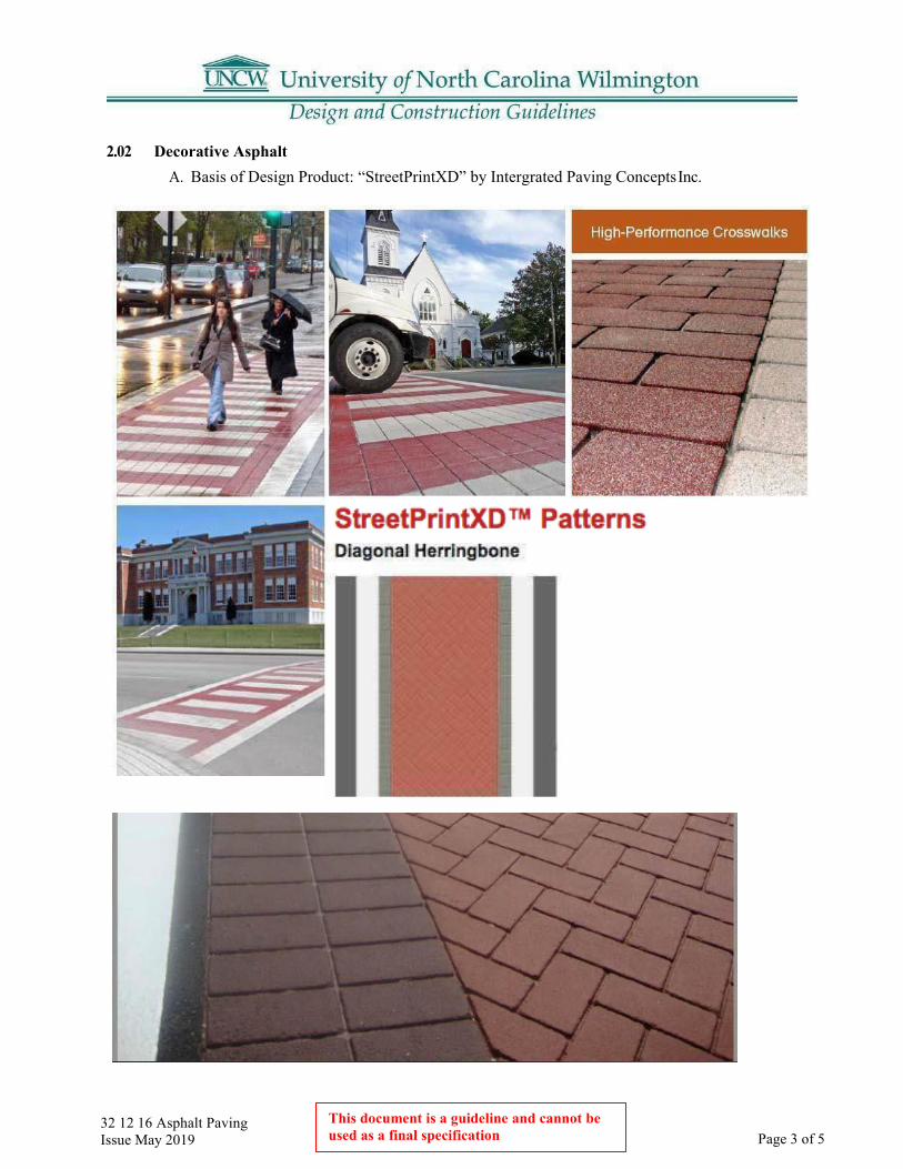
32 12 16 Asphalt Paving Issue May 2019 Page 3 of 5
This document is a guideline and cannot be used as a final specification
2.02 Decorative Asphalt A. Basis of Design Product: “StreetPrintXD” by Intergrated Paving Concepts Inc.

32 12 16 Asphalt Paving Issue May 2019 Page 4 of 5
This document is a guideline and cannot be used as a final specification
2.03 Typical Speed Hump

32 12 16 Asphalt Paving Issue May 2019 Page 5 of 5
This document is a guideline and cannot be used as a final specification
2.04 Large Speed Hump
32 90 00 Landscaping Design Guidelines Issue May 2019 Page 1 of 19 This document is a guideline and
cannot be used as a final specification
32 90 00 UNCW Landscaping Standards
Part 1: Applicability
1.01 These guidelines are for use for all UNCW properties. A. These guidelines include design, material and methods, and warranties for the following:
1. Planting, including trees and shrubs.2. Lawns and Grasses3. Tree protection4. Irrigation
Part 2: Design Guidelines – General
2.01 All new buildings shall have related landscaping and irrigation designed and installed as part of the project.
2.02 In natural areas and designated native themed areas, plant only native plants.
2.03 Use ornamentals sparingly at building entrances and corners for clear lines of visibility for safe traffic movement.
2.04 No annual planting beds are desired except as directed by UNCW Landscape Services.
2.05 Foundation plantings shall be planted so that at maturity, maintenance personnel can walk between the building face and the plant material, landscaping will be offset from buildings a minimum of 6 feet and will be designed so as not to block windows when plantings are mature. Mature plant size will address building penetrations, blank walls, windows, etc.
2.06 Provide a mulch strip at the base of the building where earth meets the building base.
2.07 Arrange plant material with safety and security issues in mind. Plant material over 3 feet in height at maturity shall be 10 feet back from the edge of walkways to ensure visual clearances.
2.08 Street trees shall be planted on every street to provide shade over the pavement. Coordinate street tree plantings with street lighting.
2.09 Locate larger trees so that leaves do not collect on rooftops.
2.10 Each tree shall have a 6-foot diameter minimum mulch ring.
2.11 Where possible locate trees in groupings within a continuous mulch bed for ease of mowing. In general, locate trees a minimum of 10 feet from paved areas.
2.12 All plant material specifications are to meet Nursery standards or better.
32 90 00 Landscaping Design Guidelines Issue May 2019 Page 2 of 19
This document is a guideline and cannot be used as a final specification
2.13 Landscape and site designs should preserve existing trees to the maximum extent possible.
2.14 All new landscape construction will be designed with an irrigation system.
2.15 All parking lot designs are to include large islands with landscaping, electricity, and water at each island.
Part 3: Design Guideline – Designer Responsibilities
3.01 The Designer is responsible for: A. Including applicable UNCW guidelines in the landscape plans and specifications. Additional
instructions and materials may be added as determined by the Designer (LandscapeArchitect).
B. Providing a description of the scope of the work on the Plans and Specifications.C. Initiating a thorough evaluation with UNCW Landscape Services and the University Arborist
with any proposed to remove an existing tree before committing to a design strategy.D. Specifying the common name and the botanical name in the plans.E. Locating for the contractor at least one plant source for each plant type specified.F. Providing irrigation plans from a scope of irrigation determined with UNCW
Landscape Services. As-Builts due at final inspection.G. Providing a maintenance plan for the plant material and a description of long-
term maintenance goals for the landscape.
Part 4: Design Guidelines – Warranties
4.01 Contractor’s Maintenance Responsibilities Until Final Acceptance: A. Maintenance and protection of the work is the responsibility of the Contractor until Final
Acceptance. Maintenance shall consist of mowing, watering, cultivation, weeding, mulching,resetting of plants to proper grades or upright positions, keeping the plants free of insectsand disease and in thriving condition.
B. If any chemical application is required during installation or the maintenance period, a copyof the applicator’s license shall be provided to the UNCW Construction Manager at the timethe contract is executed.
C. It shall be the responsibility of the Contractor to provide security or barricade the plants toprevent damage to work in place and to keep the site neat and clean in appearance until theFinal Inspection.
4.02 Final Acceptance A. After Final Acceptance, the Owner will assume all maintenance of plant material (mowing,
cultivation, weeding, mulching, keeping the plants free of insects and disease) of the site.Exceptions include the Contractor responsibilities for watering as defined in the warrantyperiod. The Contractor shall submit to UNCW Landscape Services two copies of typewrittenmaintenance plans with instructions for caring for new plantings for one full year. TheOwner shall keep records of maintenance practices during the warranty period.
32 90 00 Landscaping Design Guidelines Issue May 2019 Page 3 of 19
This document is a guideline and cannot be used as a final specification
4.03 Warranty Period Requirements A. Usually, the warranty period shall be for 12 months from the date of Final Acceptance for
plant material. The warranty period shall be for 24 months from date of Final Acceptance fornon-irrigated trees of 3” or larger caliper. For all non-irrigated plant material, the Contractoris responsible for ensuring the plants receive the equivalent of 1” of water per week duringthe guarantee period of one year. If the warranty period extends to 2 years, water 1” of waterevery two weeks in the second year.
B. The Contractor shall keep watering and maintenance records submitted monthly duringthe warranty period to UNCW Construction Management.
C. The warranty requires that plants be healthy, vigorous, and thriving for 12 months from thedate of Final Acceptance. Any replacement plants shall be inspected by the Designer andUNCW Landscape Services and Project Manager prior to planting to ensure plants are closelymatched.
D. Dead or dying plants will be documented and removed immediately by the Contractor.E. At the end of the warranty period the Designer will notify UNCW Construction Manager and
the Contractor in writing of the plants to be replaced. Replacement dates will be establishedby mutual agreement between the Designer, UNCW Landscape Services, and the Contractor.New plants shall be subject to the original warranty for that plant.
Part 5: Design Guideline – Plant Material and Methods
5.01 Plants: A. The Contractor must provide a list of sources for all plant material for the Designer’s review.B. To substitute plants shall be ordered by the Contractor without the written approval of the
Designer with agreement from UNCW Project Manager and UNCW Landscape Services.C. All plants must conform to the American Standard for Nursery Stock published by the
American Association of Nurserymen.D. Plants larger than specified may be used if approved by the Designer. Use of such plants
shall not increase the contract price. If larger plants are approved, the soil preparation mustbe increased to accommodate the size of the plant at no additional cost to the owner.
E. Plants shall be measured when branches are in the normal position. Height and spreaddimensions refer to the main body of the plant and not branch tip to tip. If a range of size isgiven, no plant shall be less than the minimum size and not less than 40% of the plants shallbe as large as the maximum size specified. The measurements specified are the minimumsize acceptable. Plants that meet the measurements specified, but do not have a normalbalance between height and spread shall be rejected.
5.02 Herbicide - Post-emergent: A. Herbicide: “Round-Up” by Monsanto or equal 41% Glyphosate product, mixed with field
marker, (written statement for future reference).B. Pre-emergent: XL2G or Snapshot (depending on plant crop) or equal, after an approved
period of establishment, to be deemed safe on all species (in the area) and approved by theUNCW Landscape Services Management.
5.03 Mulch: A. Fresh, long needle pine straw at a depth of 4”.
32 90 00 Landscaping Design Guidelines Issue May 2019 Page 4 of 19
This document is a guideline and cannot be used as a final specification
5.04 Fertilizer: A. A commercial grade fertilizer with an analysis described in the soil test. Provide copy
to UNCW.
5.05 Lime: A. Agricultural grade dolomitic lime mineral soil conditioner
5.06 Packaged Materials: A. All packaged goods including fertilizer shall arrive to the site in original unopened,
undamaged containers showing weight, analysis and name of manufacturer. Allpackaged goods shall be covered and protected from deterioration until used.
5.07 Topsoil: A. Amended soils are preferred over imported topsoil where practical.
1. Before mixing, clean topsoil of roots, plants, sods, stones, clay lumps, and otherextraneous materials harmful or toxic to plant growth.
2. Imported topsoil shall be fertile, friable, natural topsoil of loamy character, without amixture of subsoil material, reasonably free from clay, lumps, coarse sands, stone, plants,roots, sticks, and other foreign materials.
3. Soil Mixture: Soil shall be a mixture of eight parts topsoil, thoroughly mixed withthree parts peat humus and one part weed seed free manure.
4. For non-ericaceous plants, topsoil shall have a pH range between 5.8 and 6.5, total solublesalts not to exceed 500 parts per million, and clay content shall range between 5% and25%.
5. Tree Pits: Backfill for tree pits shall consist of original soil with no amendments or asshown on drawings. If the original soil is a heavy clay or unsuitable material, then thebackfill shall be amended with peat humus.
6. Tree pits located in patios, with or without grates, and other paved areas shall havesubsurface drainage structures as shown on the planting details. Backfill in these areasshall be a structural soil fill.
7. Bed Area: Topsoil shall be spread uniformly in all distributed areas to the minimumdepth shown on the following schedule:
Area Depth Width
Groundcovers, herbaceous material, bulbs, corms, tuber, etc. 6” entire bed area
Shrubbery Beds 18” entire bed area
5.08 Erosion Control Materials: A. Any materials left on the site after the end of the guarantee period shall be
biodegradable unless otherwise required and specified in the erosion control plans andspecifications.

32 90 00 Landscaping Design Guidelines Issue May 2019 Page 5 of 19
This document is a guideline and cannot be used as a final specification
5.09 Watering Bags: A. Watering bags shall be of the type that are attached to the trunk and sit vertically when
full. No flat bags that cover the root ball will be allowed.
5.10 Delivery of Plant Material: A. The Contractor shall ensure that the plants are dug within the season planted.B. The Contractor must take all precautions customary in good trade practice in preparing
plants for moving.C. Plants transported uncovered may be rejected.D. Balled & Burlapped (B&B) Plant materials in foliage must be sprayed with anti-desiccant
immediately after digging to prevent dehydration.E. Provide plants typical of their species or variety, with normal, densely developed
branches and vigorous, fibrous root systems. Provide only sound, healthy, vigorous plantsfree from defects, disease, and all forms of infestation. All plants shall have a fullydeveloped form without voids and open spaces. Plants held in storage will be rejected ifthey show signs of growth during storage.
F. Trees that have the main trunk forming a “Y” shape may be rejectedG. Trees and shrubs shall not be pruned prior to delivery to the site and shall be pruned only to
remove broken branches. No other pruning is required at planting. No new pruning woundsshall be present with a diameter of more than one inch and such wounds must showvigorous bark on all edges. Improperly pruned plants may be rejected.
H. Trees and shrubs shall not be bent or tie-bound in such a way to damage the leader or bark.I. B&B plants with cracked or broken root balls shall not be acceptable. B&B stock shall be
rejected if more than one inch of fill is found over the original root system. Plant materialhandled by the trunk or stem may be rejected. Container grown stock shall not be root-boundor with root systems hardened off.
J. The Contractor shall take precautions necessary to prevent desiccation or mechanical damageprior to, during and after delivery to the site.
K. All plants remain the property of the Contractor until final acceptance.L. Label one tree, shrub, ground cover, etc. in each planting grouping with the correct name and
size indicated on the plant list with waterproof labels that remain legible for 60 daysminimum.
5.11 Storage on the Site: A. Notify UNCW Grounds Management of delivery schedule in advance so plant material may
be inspected by UNCW Grounds Management and/or the Designer upon arrival at the jobsite. Unaccepted plant material shall be removed immediately from the job site. No plantswill go in the ground, prior to inspection.
B. Deliver trees and shrubs after preparations for planting have been completed, plantlocations are field staked, and plant immediately. If planting is delayed more than 6 hoursafter delivery, set plants in the shade, protect from weather and mechanical damage, keeproots moist, prevent freezing of the root ball, and remove ties from branches. Cool thesurface of the storage area by watering before placing plants on it. Keep plants protectedfrom strong direct or reflected light, especially tree trunks. Plants that cannot be plantedimmediately upon delivery shall be properly protected, heeled in and irrigated daily.
5.12 Herbicide Application:

32 90 00 Landscaping Design Guidelines Issue May 2019 Page 6 of 19
This document is a guideline and cannot be used as a final specification
A. Prior to using any herbicide, notify Grounds Management.B. “Round-Up” by Monsanto (or equal) shall be applied to all plant beds and mulch beds with
existing vegetation to be removed, such as in the case of changing from existing turf to mulch bed. Apply herbicide per the manufacturer’s directions. Reapply after 30 days if signs of plant growth can still be detected in treated areas.
C. To protect waterways and riparian buffers use an Aquatic formulation of Glyphosate according to manufacturer’s directions.
D. Pre-emergent XL2G or Snapshot shall be applied by the Contractor to plant beds prior to the emergence of any weed seeds but only after plants and turfgrass are deemed to be well established by consulting with UNCW Landscape Services. Pre-emergent is to be applied at rates specified on the package as recommended by the manufacturer. Select pre-emergent based on the season of effectiveness. Product must be approved by UNCW Landscape Management prior to application.
E. Weeds, grass or other undesirable plants may be removed manually in lieu of herbicides at UNCW’s discretion.
5.13 Preparation of Sub-grade Plant Beds: A. Do not work soils that are frozen, muddy or saturated.B. Rough grading shall be brought to a true and uniform grade, clear of all stones larger than
one (1) inch, sticks and other extraneous materials.C. Where the subsoil is composed of heavy clays or compacted due to construction
activity the soils shall be ripped to a minimum depth of twenty-four (24) inches.D. Ripped areas shall be brought back to a final, fine grade by the Contractor.
5.14 Clean up: A. After final grading is approved the site shall be cleared of all grade stakes, surface trash and
other objects.B. Paved areas (including streets and walks) shall be kept clean. Paved areas shall be cleaned by
mechanical means and with brooms. No water shall be used to clean paved areas. The wheelsof all vehicles shall be kept clean to avoid tracking soil onto road, walks or other paved areas.
5.15 Drainage, Detrimental Soil, Underground Utilities, and Obstructions: A. The Contractor shall notify the Designer in writing of all soil and drainage conditions
considered detrimental to growth of plant material as identified by the Contractor or in the soils report.
B. Alternate plant locations due to unforeseen conditions must be approved by the Designer, Grounds Management, and the UNCW Project Manager.
5.16 Locations of Plants on the Site: A. The Contractor shall lay out and field stake the position of all plants and beds. The Contractor
shall then notify the Designer for review and approval of the plant locations. The Designerwill notify the UNCW Project Manager and Grounds Management who may attend theinspection for field staking.

32 90 00 Landscaping Design Guidelines Issue May 2019 Page 7 of 19 This document is a guideline and
cannot be used as a final specification
5.17 Soil Amendments: A. The Contractor shall obtain a NC Department of Agriculture soils test for all areas to be
planted. Recommended amendments shall be incorporated into all areas designated asbed prepared areas.
5.18 Plant Bed Preparation: A. Add Amendments per the soil test. Till the area to achieve a granular texture to a depth of
12”. Remove all rocks over 1” in diameter, sticks, or any extraneous matter. Till in soil mixas described in item 5.07. Fine grade planting area for proper drainage according to designtopography. No pooling will be allowed. The Contractor will bear the responsibility forproper surface drainage of bed areas, as well as those areas disturbed by construction.
B. Contractor will be required to re-grade and re-prepare any areas that pond or otherwisedemonstrate poor drainage.
C. In wooded areas, “natural” areas, or reforested areas do not bed prepare entire area. Prepareonly the planting pits and root transition areas per planting details.
5.19 Excavation and Planting of Trees: A. Before digging the hole: Remove all soil from above the root flare to expose the topmost root
where it emerges from the trunk, and:1. Measure the distance between the topmost root and the bottom of the root ball. Dig the
hole about 10% shallower than this depth and as wide as possible (at least 1.5 to 3 timesthe width of the ball). The root ball should be positioned shallowly in the hole so that thefinished grade of the backfill soil and landscape soil is lower than the top of the root ball.In other words, leave the top few inches of the sides of the root ball exposed to the air.Then apply mulch so it covers the sides of the root ball. Be sure that when you arefinished planting, there is no soil, and little or no mulch, over the top of the root ball. Soil(and thick mulch layers more than 1 or 2 inches deep) over the root ball can prevent waterand air from entering the root ball. No amendments of any kind are necessary in thebackfill soil because extensive research clearly shows amendments typically do notincrease survival nor improve growth after planting. When finished planting, you shouldbe able to see the topmost root in the root ball originating from the trunk at the soilsurface, or it should be within the top inch of soil in the root ball. The trunk should bevisible. Wire baskets need to be cut at least half of the way down after the tree is placedin the pit.
2. Dense Clay, Peat, or Muck Soils: Increase the width of the pit excavationsan additional one-third (1/3) of the specified pit diameter.
3. Balled and Burlapped: Set balled and burlapped stock on a layer of compacted plantingsoil mixture, plumb and in the center of the pit or trench with top of ball at same elevationas adjacent finished landscape grades. Ball shall be placed in excavations at least twice aswide as the ball diameter and equal to the ball depth. Remove all ties around the plant’strunk and ball. No burlap twine or wire shall be pulled from under the ball. When ball isset, cut burlap down at least half way to bottom of ball, then place additional backfillaround base and sides of ball, and work each layer to settle backfill and eliminate voidsand air pockets. Water pits thoroughly after placing backfill.
4. Settling: allow for three (3) inches of planting soil mixture to settle in planting areasat initial backfilling. Before placement of mulch, add necessary additional plantingsoil mixture to achieve specified finish grade.

32 90 00 Landscaping Design Guidelines Issue May 2019 Page 8 of 19
This document is a guideline and cannot be used as a final specification
5. Container Grown Stock: When using container grown stock, excavate as specified forballed and burlapped stock and adjusted excavations to size of container width anddepth.
6. Saucers: The owner may decide that the use of saucers is not required in irrigated areas.7. Anti-Desiccant: At the direction of the owner, deciduous trees or shrubs that are
moved when in full-leaf may be sprayed with anti-desiccant at nursery before movingand sprayed again two weeks after planting.
5.20 Mulch: A. Mulch pits, trenches, beds, and planted areas. Provide no more than a 4” inch thickness of
mulch around trees and shrubs and a three-inch thickness of mulch around groundcovers,herbaceous materials and bulb beds, etc. Weed and turf suppression during establishment isessential. Apply a 4-inch thick layer of mulch around the plant to help discourage weeds. Anarea two feet in diameter for each inch of tree trunk diameter (minimum diameter should beeight feet for trees with a trunk diameter less than 3 inches) should be maintained during theestablishment period. When mulching trees, apply a 4” layer over the outer half of the rootball. This keeps the trunk dry and allows rainwater, irrigation, and air to easily enter the rootball. Mulch resting on the trunk or layered too thick can kill the plant by starving it ofoxygen, killing the bark, causing the stem and root, preventing hardening off for winter,encouraging rodent damage to trunk, keeping soil too wet, and repelling water. Mulch onthe root ball has little impact on water loss from the tree since most of the moisture thatleaves the root ball does so by transpiration, not evaporation. Only a small amount (<10%)leaves the root ball by evaporation from the surface of the root ball. Preferred mulch is freshlong- leaf pine straw.
5.21 Staking: A. Trees shall be staked according to the planting detail in a plumb position immediately after
planting. Stakes shall be placed in undisturbed soil adjacent to tree planting pits and under nocircumstance placed in tree pits. In many instances, if foot balls are heavy enough, stakesare not necessary. Stake to stabilize the root ball. Most field grown trees do not need stakingbecause their root balls are heavy enough to stabilize the tree in the ground. Some containergrown trees will require staking in open areas since root balls are much lighter in weight.
B. Guy wires or other guying material shall be encased in hose to prevent direct contact withbark of the tree and shall be placed around the trunk in a single loop sized a minimum ofthree (3) times the caliper of the tree. Wires shall be tightened and kept taut by turnbuckles.Other guying materials shall also be regularly tightened and kept taut by the Contractor.
5.22 Pruning: A. If required and only after approval by the owner, each tree and shrub shall be pruned in
accordance with standard horticultural practice to preserve the natural character of the plant.Pruning shall be done with clean, sharp tools. The bruised or broken parts of large or fleshyroots shall be cut off smoothly before planting. All cuts on trees shall be made outside of thebranch collar back to the main trunk or branch. Evergreen plants shall not be pruned exceptto remove dead or broken branches.
5.23 Watering: A. The Contractor shall provide water unless the plantings are irrigated.B. Containerized plants shall be watered immediately prior to planting. Thoroughly water plants
immediately after planting to thorough saturation of all backfill in the pits and beds duringthe same day of planting. When fully settled, the plants should be at the proper grades andvertical.

32 90 00 Landscaping Design Guidelines Issue May 2019 Page 9 of 19 This document is a guideline and
cannot be used as a final specification
C. Apply water only by open-end hose at low pressure. Sufficient water is achieved by filling root zone twice per application per tree and per shrub. Rain substitutes for a scheduled watering when at least two inches of rainfall has been verified. It is the responsibility of the Contractor to keep the plant root zone moist enough to establish healthy and attractive plant material.
D. Watering requirements during the initial shock period (first 30 days after planting) shall be every day for the first three days; every other day for ten days; twice per week fortwo weeks.
E. Watering requirements during the establishment period (warranty period), after the first 30 days shall be 1” of water per week for one year.
5.24 Inspections and Acceptance: A. Request for Inspections shall be made 7 days before the anticipated date of inspection.
5.25 Planting Shrubs, Ground Covers, Herbaceous Materials, Bulbs, Corms, Tubers, etc.: A. Space plants as indicated in the planting plan. Dig holes large enough to allow for
spreading of roots and backfill with planting soil. Work soil around roots to eliminate airpockets. Water plants thoroughly after planting, taking care not to cover crowns of plantswith wet soil.
B. Plant bulbs, corms, tubers, etc. at a depth equal to three (3) times the width of the item beingplanted. Back-fill with plant mix/ if bulbs, corms, tubers, etc. are to be placed under otherherbaceous materials, place other herbaceous materials first and then plant bulbs, etc.
Part 6: Design Guide – Lawns and Grasses
6.01 General: A. Scope of Work: Provide seedbed preparation, liming, fertilization, seeding, and mulching
of all newly graded finish earth surfaces, unless indicated otherwise, and all areas inside oroutside the limits of construction that are distributed by the Contractor’s operation and allareas identified as “lawn” or “sod”. Seeded areas shall be hydro seeded, except small areasthat are inaccessible to the hydro seeding equipment, which shall be drill seeded.
6.02 Submittals: A. Certificates of Conformance – Contractor shall furnish Certificates of Conformance from
manufactured or agencies for the following prior to application: Seed Fertilizer Lime Soil(Soil Testing Recommendation – NC Department of Agriculture)
6.03 Manufacturer’s Literature: A. Manufacturer’s Literature that includes physical characteristics, application and installation
instructions and recommendations for the following: Hydraulic Mulch Material ANDErosion Control Material
6.04 Delivery: A. Fertilizer and Lime – Deliver materials to the site in the original, unopened containers bearing
the manufacturer’s chemical analysis, name, trade name, trademark, and indication ofconformance to state and federal laws. In lieu of containers, furnish fertilizer and lime in bulkwith a certificate indicating the information described above with each delivery.
B. Seed – Deliver seed to the site in original sealed packages bearing the producer’sguaranteed analysis for percentages of mixtures, purity, germination, weed seedcontent, and inert
32 90 00 Landscaping Design Guidelines Issue May 2019 Page 10 of 19
This document is a guideline and cannot be used as a final specification
material. Label in conformance with the USDA Federal Seed Act, any other statues, rules and regulations and applicable state seed laws. Wet, moldy, or otherwise damaged seed will be rejected.
6.05 Installation: A. Lawns / areas to be grassed shall be at finish grade prior to seeding, etc. and this grade
shall be maintained.B. Permanent grass type shall be as agreed upon by the Owner’s Landscape Services
Superintendent as to type and location.C. Grassed areas installation preferences within budget constraints are:
1. sod installation2. sprigging3. hydroseeding4. seeding
D. A soils analysis shall be prepared by a testing agency approved by the Designer. Thecontractor shall provide all soils recommended by the analysis.
E. Fertilizer selection and application rate shall be as determined by soil analysis. Fertilizershall be a commercial fertilizer delivered in unopened, original containers each bearing themanufacturer’s guaranteed analysis. Any fertilizer which becomes caked or otherwisedamaged, shall not be accepted.
F. The care of the lawn shall be the responsibility of the contractor until the project isaccepted. Lawn care shall include watering, feeding, and cutting consistent with generalpractice of care for the type of lawn.
G. The contractor shall guarantee a live stand of permanent grass consisting of 95% coverageminimum for seeded grass with no bare spots greater than one (1) square foot. Acceptanceshall be made after the grass has been mowed at least once and shows sufficient stand andcover as specified.
H. The contractor shall fully maintain the lawn through the warranty period except for themowing, fertilization and watering after acceptance. The Owner will be responsible formowing and watering, but this will not void the warranty.
I. Every effort is to be made to schedule planting to ensure the greatest chance of survivabilityfor the planting.
J. Storage and Handling:1. Store lime, fertilizer, and seed in dry locations away from contaminants. Protect seed from
drying out. When handling materials, do not drop or dump from vehicles.
6.06 Products: A. Seed: Only state-certified seed of the latest season’s crop shall be used, and it shall be free
from any noxious weed seed.B. Sod: Sod shall consist of Bermuda Type 419 “Tifway” or Centipede. The Owner shall make
choice at time of installation.C. Fertilizer: Commercial grade, free flowing, uniform in composition and bearing the
manufacturer’s guaranteed statement of analysis as recommended by the results of the required soil analysis.

32 90 00 Landscaping Design Guidelines Issue May 2019 Page 11 of 19 This document is a guideline and
cannot be used as a final specification
D. Mulch: Free from noxious weeds, mold, or other deleterious material. Provide wood cellulosefiber when hydro-seeding.
E. Straw – Straw shall consist of stalks from oats, wheat, rye, barley, or rice. Furnish straw ofair-dry condition and of proper consistency for placement with commercial mulch-blowingequipment.
6.07 Execution: A. Preparation:
1. Seed Bed – Areas to be seeded shall be brought to the required sub-grade. New areas to beseeded shall be thoroughly tilled to a minimum depth of four (4) inches by scarifying,disking, harrowing, or other approved methods. Remove debris and stones larger than one(1) inch from all areas to be seeded.
2. Fertilizer and Lime – Apply fertilizer and lime at the rates described in this specificationor as recommended by the required NC Department of Agriculture Soil Tests.
3. Drill Seeding – Incorporate fertilizer and lime into the soil to a minimum depth of four (4)inches. Application may be performed as part of the tillage operations.
4. Hydro-seeding – Apply liquid fertilizer in amounts recommended by NC Departmentof Agriculture Soil Tests. Apply lime manually.
6.08 Seeding Operations A. Seed Rates – Seed combinations are to be utilized at rates shown according to calendar dates
of seeding operations.B. Grades – Grades on the areas to be seeded that have been established previously shall be
maintained in a true and even condition.C. Disturbed Areas – In disturbed areas to be seeded, the Contractor will be responsible for
insuring that the soil present in these areas is friable and capable of sustaining a stand ofgrass acceptable to the Owner.
D. Soil Amendments – Before seeding operations, the soil shall be amended as follows:1. Fertilizer shall be uniformly distributed at the rates recommended by the required
NC Department of Agriculture Soil Tests.2. Lime shall be uniformly distributed at the rates described in this specification or as
recommended by the required NC Department of Agriculture Soil Tests.Amendments shall be incorporated into the soil by disking, harrowing, or otheracceptable method.
E. Seeding Method – Seed shall be broadcast either by hand or approved sowing equipment.One half (1/2) of seed mix shall be distributed with the sower moving in one direction, andthe remaining one half (1/2) shall be sown with the sower moving at right angles to thefirst sowing.
F. Seed Distribution – Seed distribution on the ground surface shall be covered to a depth not toexceed one half (1/2) inch by raking or other approved method.
G. Seed Compaction – Immediately after the seeding operations have been completed, the entireseeded area shall be compacted by means of a roller or other approved equipment.
H. Hydro-Seeding – Mix seed, fertilizer, and wood cellulose fiber in required amount of water toproduce a homogeneous slurry. After seed, water, and fertilizer have been thoroughly mixed,add one thousand and five hundred (1,500) pounds of wood cellulose fiber per acre (dryweight) and apply the slurry. Seed shall not remain in agitated water containing fertilizer formore than one (1) hour before application.

32 90 00 Landscaping Design Guidelines Issue May 2019 Page 12 of 19
This document is a guideline and cannot be used as a final specification
I. Mulching – Straw-mulch shall be spread uniformly in a continuous blanket using seventy- five (75) pounds per one thousand (1,000) square feet over the entire seeded area. After thestraw-mulch has been applied, it will be tacked in place by a disc or other suitableequipment.
J. Watering – The mulched and seeded areas shall be sprinkled with water applied in a lightspray until the seedbed is thoroughly moist to a depth of one (1) inch. Sprinkling shall becontinued during dry weather to ensure a good stand of grass.
K. Initial Maintenance – The contractor shall be responsible for care of seeded areas while grassis becoming established. Mowing of the seeded areas shall be the responsibility of theContractor within the establishment period with approved mowing equipment to a height oftwo (2) inches when average height of grass becomes three (3) inches.1. Establishment Period – The establishment period shall be one (1) month or as required to
obtain a complete stand of mowable grass which is acceptable by the Owner.
6.09 Sodding Operations: A. General
1. Sod shall consist of Centipede Grass (Eremochloa ophiuroides). or Common Bermuda,(Cynbdon dactylon) of the variety described in this specification and shall be free ofweeds and undesirable plants large stones or roots.
B. Grades1. Grades on the areas to be sodded that have been established previously shall be
maintained in a true and even condition.C. Sodding Specifications
1. Sod shall be weed free, free of undesirable plants, large stones or roots.2. Herbicide – Entire area to be sodded should be sprayed with the non-selective 41%
Glysophate product.3. Waiting Period – Allow at least forty-eight (48) hours post – herbicide application before
tilling and grading begins.4. Tilling and Grading – Area should be tilled to a depth of six to eight (6-8) inches and
raked to a true and even condition about one (1) inch below grade.5. Placement – Sod shall be laid smoothly, edge-to-edge and with staggered joints. Sod shall
be pressed immediately into firm contact with the soil by tamping or rolling so as toeliminate all air pockets, provide a true and even surface and assure knitting withoutdisplacement of the sod or deformation of the surfaces of sodded areas
6. Rolling – Sod shall be mechanically rolled immediately to firmly contact the soil,eliminate all air pockets and provide a true and even surface to assure knitting, withoutdisplacement of the sod, or deforming the surface of the sodded areas.
7. Watering – After the sodding operation is complete, sufficient water shall be appliedto wet the sod completely, and wet at least 2” of the soil below the sod.
8. Initial Maintenance - The Contractor shall be responsible for the care of the sodded areaswhile grass is becoming established. The establishment period should be one (1) month oras required to obtain a complete stand of mowable grass that is acceptable to the Owner.The Contractor shall mow sodded areas within establishment period with approvedmowing equipment to the proper recommended height for the species.

32 90 00 Landscaping Design Guidelines Issue May 2019 Page 13 of 19 This document is a guideline and
cannot be used as a final specification
9. Establishment Period- The establishment period shall be one month with adequate averagetemperature for germination to occur or as required to obtain a complete stand of mowablegrass which is acceptable to the owner.
6.10 Protection of Seeded and Sodded Areas: A. Immediately after seeding and sodding operations, protect the areas against traffic and
other uses by erecting barricades, as required, and by placing approved signs at appropriateintervals until final acceptance by the owner.
Part 7: Design Guideline – Tree Protection
7.01 Before work begins: A. Agreement will be reached with site manager and Campus Arborist on specific trees that
will be preserved. Communication between site manager, property owner, and Arborist isessential for success until project is completed.
7.02 Intent: A. Individual trees and/or groups of trees identified for protection during construction operations
shall be fenced and protected. For highly developed, high traffic campus sites and category 1trees, a 5-foot high, chain link tree protection fence is required. For short construction periodsof approximately three months or less, and for construction projects in less developed, lowtraffic areas metal poles with orange plastic barricade or wood tree protection fencing may beused. Every 50 linear feet of tree protection fence shall have a sign that says “ Tree ProtectionArea Do Not Enter” using 2” minimum height black letters on white background. At least onesign is required. This fencing may not be removed without the consent of the UNCW ProjectManager and permission from the UNCW Construction Manager. Request for tree protectionfence removal or any change from the contract documents regarding tree protection shall bemade to Construction Management prior to any action. All trees to remain shall be watered 1”of water per week if rainfall does not meet 1” per week.
7.03 Tree Survey: A. All trees on campus construction and development sites shall be surveyed. Large wooded
areas or groups of trees shall be identified as a cluster on the survey. Major trees within thesegroupings, as determined by the Designer with the Campus Arborist, shall be numbered andsurveyed according to size and type. Individual trees surveyed, or key trees identified by theDesigner or campus arborist shall be drawn to scale with the approximate canopy shown.Trees to be saved or removed shall be identified by the Designer and Campus Arborist andindicated on the site plans. As determined by the Designer, Campus Arborist, or UNCWDesign Project Manager, trees outside the construction area at risk to construction damagealso may be identified to remain and be protected.
7.04 Tree Protection Area: A. Establish the critical root zone of the trees to remain and identify this area on the plans. A
general rule for establishing the critical root zone is to measure and protect an area 1.5 timesthe canopy spread. Consult with the University Landscape Architect and Campus Arborist todefine the critical root zone area and shape of the area to be protected during construction.Establish the limits to grading and tree protection fence to protect the largest amountpossible of the critical root zone.
B. No materials, equipment, vehicles, or people may enter into the tree protection area. Allowno poisoning to trees with the dumping of materials such as solvents, gas, paint, andherbicides

32 90 00 Landscaping Design Guidelines Issue May 2019 Page 14 of 19
This document is a guideline and cannot be used as a final specification
or with the washing of toxic materials into the tree protection area. Exercise care that no runoff from cleanup operations (including concrete clean up wash water) enters the tree protection areas.
7.05 Tree Watering Plan: A. All trees to remain shall receive 1” water per week. Surface drip irrigation may be
laid throughout the root zone and covered with 2” composted chipped hardwoodmulch.
7.06 Pruning: A. The contractor shall not remove or prune any landscape materials without prior consent from
the Owner. All tree work shall be by an Arborist certified by the International Society ofArboriculture, bonded, and insured. All work shall be according to standards set forth in theANSI A300 publication Pruning Standards for Shade Trees, published by the NationalArborist Association. Request for any tree or shrub pruning shall be directed to the CampusArborist. Request for any tree removal shall be directed to the UNCW Construction Managertwo weeks in advance. The UNCW Construction Manager will initiate a tree removalprocess with Grounds Maintenance. Any inadvertent injury to trees shall be cared for by aCertified Arborist and paid for by the contractor.
B. If plans require grading or digging in the critical root zone of protected trees, root prunethe tree to avoid the ripping of roots with digging equipment. This may be accomplishedwith a trencher. Any roots larger than ½” that are damaged due to cut grading or trenchingoperations must be stubbed cleanly.
7.07 Disposal of Trees to be Removed: A. All debris from the pruning operation shall be disposed of lawfully off Campus.
7.08 Boring: A. Boring is required under major trees designated to remain to avoid root damage for utility
construction. This option is preferred, include direction to the contractor in the plans andspecifications for location and size of boring pits and the direction and location of the bore.
7.09 Tree Preparation: A. Trees may be prepared for damage to the root zone in advance of construction. Evaluate with
the campus arborist the need for supplemental watering in the critical root zone to remain.
7.10 During Construction: A. In areas where construction vehicular and equipment traffic over tree roots is unavoidable,
place 12" of bark mulch or coarse wood chips as an organic base for traffic. In areas requiringrepetitive construction traffic access place a layer of structural geo-textile fabric under thewood chips, and logging mats on top of the mulch and cover with additional layer of woodchip mulch. Chipped wood may be used for a temporary pedestrian path over rootzones.1. When excavating avoid cutting roots larger than 2”. When this is not possible, shovel
by and saw the root. Accidentally broken or crushed roots must be cut cleanly betweenthe wound and the trunk to prevent decay.
2. Raising the grade more than 6” around a tree to be preserved will require retainingwall beyond the existing dripline.
3. If grade must be lowered, terracing as far from the tree trunk as possible will be requiredto preserve as many roots as possible. This can be done in steps for a more naturalgrade.

32 90 00 Landscaping Design Guidelines Issue May 2019 Page 15 of 19 This document is a guideline and
cannot be used as a final specification
When the grade must be lowered completely, construction of an island at the drip line will be required.
4. A heavy plastic tarp must be spread in concrete mixing areas and areas where sheetrockwill be cut. The alkalinity of these materials can change soil Ph.
5. Paint brushes and tools will not be cleaned over tree roots.6. Chemical wastes (paint thinner, etc.) will be disposed of properly and drained offsite.7. Even when barriers are erected, accidental breaks and scrapes may occur. Watch for
damage and report this to Landscape Services promptly. Do not attempt pruning or repairwork. Campus Arborist will determine best methods as they relate to the extent of injury.
7.11 Trenching: A. When trenching near trees, use ISA standards. In areas where trenching or digging is allowed
near trees to remain, store earth outside the critical root zone on the side of the trench awayfrom the tree trunk to minimize compaction. If large tree roots are encountered, hand digaround the root and allow it to span the trench. During mechanical backfilling operations,use a tarp or plywood to prevent backhoe or dozer blade from cutting into the soil surface.The remaining clean up shall be by hand.
B. Refill open trenches as soon as possible. Root death can occur in 10 minutes if unfavorableweather conditions occur. Exposed roots in open trenches must be kept moist with a hose orsprinkler.
7.12 Clean up: A. All cleanup operations shall avoid any disturbance to the original grades and surface soil in
the tree protection area. Clean up in tree protection areas may be accomplished only by handraking.
7.13 Documentation by the Designer: A. Tree Protection Plan:
1. A separate tree protection plan sheet shall be required if tree protection involves morethan a simple tree protection fence. When digging, planting, trenching, boring, watering,driving in the critical root zones, or other special root zone protection is required, aseparate Tree Protection Plan describing procedures is necessary. (See Specification forTree Protection on Construction Sites – Karen Tobiassen C.A.)
2. Actual, tree protection fence locations shall be shown to scale on all site plans as well asdescribed in the specifications. Trees to be saved or removed shall be labeled as such onall site layout drawings as well as being shown on the demolition plan and grading plans.This includes electrical, plumbing, planting, etc.
7.14 Grades of Protected Trees: A. If grade must be lowered, terracing as far from the tree trunk as possible will be required to
preserve as many roots as possible. This will be done in steps for a more natural grade.When the grade must be lowered completely, construction on an island at the dripline will berequired.
B. Raising the grade more than 6” around a tree to be preserved will require a retainingwall beyond the existing dripline.1. Specifications must incorporate pertinent materials and methods used to protect trees.

32 90 00 Landscaping Design Guidelines Issue May 2019 Page 16 of 19
This document is a guideline and cannot be used as a final specification
7.15 Penalties: A. Specifications must describe that the Designer or the UNCW Construction Manager may
issue a stop work order if any portion of the tree protection fence or methods areviolated. This order remains effective until the protection is reinstated according to thecontract documents with no penalty to the owner.
Part 8: Design Guideline Irrigation
8.01 Design Criteria:
A. UNCW has a pond reuse system on campus for the majority of the water used for irrigation.Connection or local improvement of the irrigation system should be in consideration prior to anynew irrigation design. Consult UNCW Grounds Management and UNCW Project Manager.
B. Turfgrass and mulched bed and tree rings shall be on separate zones.C. Sleeves are required under all paved areas and should be 2” larger than the pipes specific.D. Irrigation will be designed to be installed prior to the installation of sidewalks. All sleeves under
paved areas shall be marked.E. Irrigation lines installed underground are to have wire tracer lines installed above the lines,
including lateral lines.F. All irrigation systems shall be designed according to UNCW guidelines. Design-Build irrigation
systems will not be accepted at UNCW. No irrigation shop drawing will be approved without anaccurate irrigation site plan with the irrigation design that is in accordance with all the designguidelines. All irrigation shop drawings shall be reviewed and approved by the Designer and byGrounds Management prior to installation.
G. UNCW preferred alternate is the “Hunter” brand irrigation system components.
8.02 The Designer is responsible for:
A. Developing the scope of irrigation for turf and planting areas with Grounds Management.B. Determining the water supply location and detailed description of the contractor’s work for
providing water supply to the irrigation site, including the location of the controller and acalibrated water meter; and water meter supply gravel for drainage, as applicable.
C. Determining the electrical supply location and source for the controller and if an electrical meter isrequired;
D. measuring, researching, or ordering survey information for campus utilities, trees over 3.5” caliper,and delineation of turf and mulch locations;
E. ensuring all city and state plumbing code requirements are met and specifyingpressure requirements of main and lateral lines;
F. separate irrigation zones for turf;G. separate irrigation zones for trees and shrubs;H. providing actual locations of heads on plans;I. pre-qualifying bidders with 3 years or more experience installing irrigation systems of comparable
scope;J. design of an above ground Reduced Pressure Back Flow Device (RPZ) with cover, as applicable;K. including site repair and seeding schedule in the specifications;L. providing as built drawings, due at final inspection.

This document is a guideline and cannot be used as a final specification
8.03 Irrigation Materials and Methods
A. Back Flow:1. The RPZ will be on copper or brass risers 1 inch or larger. The base of the risers at
ground level will have unions for winter removal. Provide heat tape.2. The RPZ will be mounted at least 12 inches but no more than 30 inches from the
relief valve to the ground.3. A brass ball valve and box will be installed 2 feet from the supply to the backflow
for quick shutdown. Also, ball valve on incoming supply line backflow.4. The RPZ will be tested and a certified report sent to UNCW Construction Manager.
B. Hot Box:1. All RPZ will have a hotbox enclosure. Preferred color is Dark Green. Hot box to be bolted down, not to be unsecure.
C. Controller:1. The controller shall have multiple start times and programs. Controller is to be hardwired
and sealed in a locked utility box. UNCW preferred alternate is a Hunter ACC.D. Valves:
1. Valves shall be Hunter electrically controlled automatic control systems diaphragmactuated and hydraulically operated solenoid valves. All Valves and wire splices will bein a 12"X9" valve box. Flow control and needle valves required.
E. Mainline:1. Mainline shall be sized to requirements and shall be a minimum of 24” below finish grade.
F. Lateral Line:1. Lateral lines shall be 1-inch minimum and at least 12 inches below finish grade wired
for location (no tape).G. Sleeves:
1. All sleeves are required under roads and walkways and shall be of Schedule 40 PVC and amaximum depth of 24 inches. No multi-strand wiring.
H. Drip Irrigation:1. Trees and shrubs in grated pits only.
I. Spray Heads:
1. Institutional Hunter six-inch spray heads with check valves will be used for rotor turfirrigation.
2. All large turf areas will have a gear driven Institutional Hunter rotor sized for the area.3. Drip irrigation will be used on all plant beds and tree rings.
32 90 00 Landscaping Design Guidelines Issue May 2019 Page 17 of 19

32 90 00 Landscaping Design Guidelines Issue May 2019 Page 18 of 19
This document is a guideline and cannot be used as a final specification
J. Quick Couplers:1. All quick couplers will be installed on swing joints and secured with ground anchors,
surrounded with gravel in a 10-inch box.K. Trenching and Backfilling:
1. All trenching will be 6 inches wide minimum. Hand trenching is required to prevent rootdamage to trees. All backfill will be tamped and disturbed area reseeded or mulched.UNCW Landscaping Services to inspect irrigation before trenches are backfilled.
Part 9: Other Landscaping Standards
9.01 Site Furnishings: See Section 12 93 00 Site Furnishings
9.02 Seating Walls: See Section 32 00 00 Exterior Improvements
9.03 Screen Walls: See Section 32 00 00 Exterior Improvements
9.04 Paving and Surfacing: See Section 32 00 00 Exterior Improvements
9.05 Parking Lots: Section 32 00 00 Exterior Improvements
Part 10: Maintenance
10.01 General: A. The Contractor is responsible for any and all maintenance activities required until final
acceptance of the planted areas by the Owner. Upon completion of the landscape planinstallation and final acceptance of the project by the Owner, maintenance activities asdescribed in the maintenance instructions supplied by the Contractor shall become theresponsibility of the Owner. Any necessary plant replacement occurring during thewarranty period remains the responsibility of the Contractor as described in the WarrantySection of the contract.
10.02 Watering: A. It shall be the Contractor’s responsibility to water all plants during and immediately after
planting and a minimum of once a week unless unusual wet weather or soil conditions exist,or an irrigation system is in operation until final acceptance of the project by the Owner. Ateach watering the soil around each plant shall be thoroughly saturated. The equivalent of one(1) acre-inch of water minimum shall be applied per week minus any measurablerainfall occurring during that week.
10.03 Plant Material Care: A. Until final acceptance of the project by the Owner, maintain trees, shrubs, and other plants
by weeding as required for healthy growth. Tighten and repair stake and guy supports andreset trees and shrubs to proper grades or vertical position as required. Restore or replacedamaged wrappings. Spray as required keeping trees and shrubs free of insects and disease.

32 90 00 Landscaping Design Guidelines Issue May 2019 Page 19 of 19
This document is a guideline and cannot be used as a final specification
10.04 Tree Wrap, Stake and Guy Wire Removal: A. Tree wrap, stakes, guy wires and other guying materials may or may not be removed by
the Contractor at the conclusion of the one (1) year guarantee period at the discretion ofthe Owner.
Part 11: Clean-up and Protection
11.01 During landscape work, keep pavements and sidewalks clean and work area in an orderly condition. During and at the conclusion of landscape work, remove tire marks and other stains or discolorations resulting for the landscape work from paved surfaces.
11.02 Protect landscape work and materials from damage due to landscape operations, operations by other contractors and subcontractors. Maintain protection during installation and maintenance periods until date of acceptance by the Owner.
11.03 All pavement, grassed and planted areas, structures and sub-structures disturbed due to the execution of this work shall be restored to their original conditions. Rework any eroded landscape areas resulting from the completion of this work.
11.04 During the course of planting, the site shall be kept clean. Excess and waste materials shall be continuously and promptly removed. Lawn areas are to be kept clear and all reasonable precautions taken to avoid damage to existing structures, plants and grass.
Part 12: Inspection and Acceptance
12.01 When landscape work is completed, including any required maintenance, the Owner will make an inspection to determine acceptability.
12.02 When inspected landscape work does not comply with requirements, replace rejected work and continue specified maintenance until re-inspection occurs by the Owner and the project is found to be acceptable. Remove any rejected plants and materials promptly from the project site.