Design Guidelines for Drinking-Water Systems · · 2014-02-18Design Guidelines for Drinking-Water...
311
Design Guidelines for Drinking-Water Systems 2008 Ministry of the Environment
Transcript of Design Guidelines for Drinking-Water Systems · · 2014-02-18Design Guidelines for Drinking-Water...
Design Guidelines
for
Drinking-Water Systems
2008
Ministry of the Environment

ISBN 978-1-4249-8517-3
Ministry of the Environment
Design Guidelines
for
Drinking-Water Systems
2008
PIBS 6881e

Design Guidelines for Drinking-Water Systems Acknowledgements
2008 i
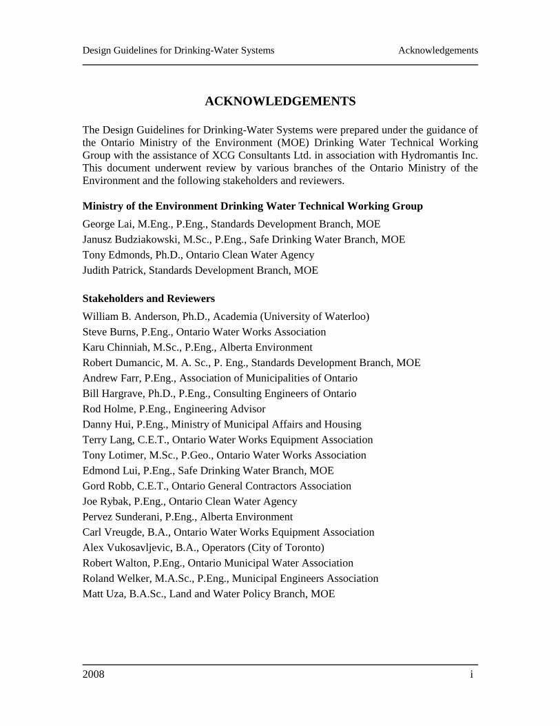
ACKNOWLEDGEMENTS
The Design Guidelines for Drinking-Water Systems were prepared under the guidance of
the Ontario Ministry of the Environment (MOE) Drinking Water Technical Working
Group with the assistance of XCG Consultants Ltd. in association with Hydromantis Inc.
This document underwent review by various branches of the Ontario Ministry of the
Environment and the following stakeholders and reviewers.
Ministry of the Environment Drinking Water Technical Working Group
George Lai, M.Eng., P.Eng., Standards Development Branch, MOE
Janusz Budziakowski, M.Sc., P.Eng., Safe Drinking Water Branch, MOE
Tony Edmonds, Ph.D., Ontario Clean Water Agency
Judith Patrick, Standards Development Branch, MOE
Stakeholders and Reviewers
William B. Anderson, Ph.D., Academia (University of Waterloo)
Steve Burns, P.Eng., Ontario Water Works Association
Karu Chinniah, M.Sc., P.Eng., Alberta Environment
Robert Dumancic, M. A. Sc., P. Eng., Standards Development Branch, MOE
Andrew Farr, P.Eng., Association of Municipalities of Ontario
Bill Hargrave, Ph.D., P.Eng., Consulting Engineers of Ontario
Rod Holme, P.Eng., Engineering Advisor
Danny Hui, P.Eng., Ministry of Municipal Affairs and Housing
Terry Lang, C.E.T., Ontario Water Works Equipment Association
Tony Lotimer, M.Sc., P.Geo., Ontario Water Works Association
Edmond Lui, P.Eng., Safe Drinking Water Branch, MOE
Gord Robb, C.E.T., Ontario General Contractors Association
Joe Rybak, P.Eng., Ontario Clean Water Agency
Pervez Sunderani, P.Eng., Alberta Environment
Carl Vreugde, B.A., Ontario Water Works Equipment Association
Alex Vukosavljevic, B.A., Operators (City of Toronto)
Robert Walton, P.Eng., Ontario Municipal Water Association
Roland Welker, M.A.Sc., P.Eng., Municipal Engineers Association
Matt Uza, B.A.Sc., Land and Water Policy Branch, MOE


Design Guidelines for Drinking-Water Systems Historical Note
2008 ii
HISTORICAL NOTE
Since the establishment of the Ontario Water Resources Commission under the Ontario
Water Resources Act (1956), the commission engineers used the Ten States Standards for
Water Works as the reference design guidelines for sanitary engineering practice. These
publications were prepared, edited and published, approximately every five years, by the
Great Lakes Upper Mississippi River Board of State Public Health Engineers and Great
Lakes Board of Public Health Engineers. The commission engineers had also developed
and applied internal advisory water works design guidelines based primarily on the Ten
States Standards and included design, construction and operational experience specific to
Ontario.
This practice has continued after the establishment of the Ministry of the Environment in
1973. The Province of Ontario joined the Great Lakes-Upper Mississippi River Board of
State and Provincial Public Health and Environmental Managers and the Ten States
Standards Water Supply Committee in 1977.
Over the years, engineering design criteria based on generally accepted good engineering
practice in Ontario have been developed and the following ministry guidelines were
published:
Guidelines for the Design of Water Treatment Works (1982)
Guidelines for Water Distribution Systems (1979, 1985)
Guidelines for Water Storage Facilities (1979, 1985)
Guidelines for Servicing in Areas Subject to Adverse Conditions (1985)
Guidelines for Water Supply for Small Residential Developments (1985)
Guidelines for Seasonally Operated Water Supply Systems (1985)
These guidelines have been revised and updated based on Ontario-specific engineering
practice, the latest Ten States Standards (Recommended Standards for Water Works,
2003) and other relevant North American design guidelines and published as the Design
Guidelines for Drinking-Water Systems (2008).

Design Guidelines for Drinking-Water Systems Preamble
2008 iii
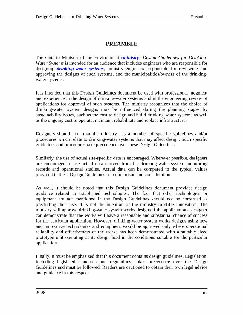
PREAMBLE
The Ontario Ministry of the Environment (ministry) Design Guidelines for Drinking-
Water Systems is intended for an audience that includes engineers who are responsible for
designing drinking-water systems, ministry engineers responsible for reviewing and
approving the designs of such systems, and the municipalities/owners of the drinking-
water systems.
It is intended that this Design Guidelines document be used with professional judgment
and experience in the design of drinking-water systems and in the engineering review of
applications for approval of such systems. The ministry recognizes that the choice of
drinking-water system designs may be influenced during the planning stages by
sustainability issues, such as the cost to design and build drinking-water systems as well
as the ongoing cost to operate, maintain, rehabilitate and replace infrastructure.
Designers should note that the ministry has a number of specific guidelines and/or
procedures which relate to drinking-water systems that may affect design. Such specific
guidelines and procedures take precedence over these Design Guidelines.
Similarly, the use of actual site-specific data is encouraged. Wherever possible, designers
are encouraged to use actual data derived from the drinking-water system monitoring
records and operational studies. Actual data can be compared to the typical values
provided in these Design Guidelines for comparison and consideration.
As well, it should be noted that this Design Guidelines document provides design
guidance related to established technologies. The fact that other technologies or
equipment are not mentioned in the Design Guidelines should not be construed as
precluding their use. It is not the intention of the ministry to stifle innovation. The
ministry will approve drinking-water system works designs if the applicant and designer
can demonstrate that the works will have a reasonable and substantial chance of success
for the particular application. However, drinking-water system works designs using new
and innovative technologies and equipment would be approved only where operational
reliability and effectiveness of the works has been demonstrated with a suitably-sized
prototype unit operating at its design load in the conditions suitable for the particular
application.
Finally, it must be emphasized that this document contains design guidelines. Legislation,
including legislated standards and regulations, takes precedence over the Design
Guidelines and must be followed. Readers are cautioned to obtain their own legal advice
and guidance in this respect.

Design Guidelines for Drinking-Water Systems Table of Contents
2008 iv
TABLE OF CONTENTS
ACKNOWLEDGEMENTS ........................................................................................................... i
HISTORICAL NOTE ................................................................................................................... ii
PREAMBLE ................................................................................................................................. iii
LIST OF TABLES ...................................................................................................................... viii
CHAPTER 1: LEGISLATIVE FRAMEWORK ..................................................................... 1-1
1.1 GENERAL .................................................................................................................................... 1-1 1.2 APPLICABLE LEGISLATION ADMINISTERED BY THE MINISTRY .................................. 1-1 1.3 DRINKING WATER REGULATIONS & SUPPORT DOCUMENTS ........................................ 1-2 1.4 OTHER APPLICABLE LEGISLATION ...................................................................................... 1-2 1.5 MINISTRY APPROVAL PROGRAM FOR DRINKING-WATER SYSTEMS .......................... 1-3 1.6 LEGAL CONSIDERATIONS ...................................................................................................... 1-4
CHAPTER 2: PROJECT DESIGN DOCUMENTATION .................................................... 2-1
2.1 GENERAL .................................................................................................................................... 2-1 2.2 STAGE 1 DOCUMENTS ............................................................................................................. 2-2 2.3 STAGE 2 DOCUMENTS ............................................................................................................. 2-3 2.4 STAGE 3 DOCUMENTS ............................................................................................................. 2-7
CHAPTER 3: GENERAL DESIGN CONSIDERATIONS .................................................... 3-1
3.1 GENERAL .................................................................................................................................... 3-1 3.2 PRE-DESIGN STUDY ................................................................................................................. 3-2 3.3 TECHNOLOGY DEVELOPMENT ............................................................................................. 3-3 3.4 DESIGN FLOW ............................................................................................................................ 3-5 3.5 WATER CONSERVATION ....................................................................................................... 3-10 3.6 PLANT CAPACITY RATING ................................................................................................... 3-11 3.7 SITE SELECTION CRITERIA ................................................................................................... 3-14 3.8 PLANT/ BUILDING LAYOUT .................................................................................................. 3-15 3.9 HYDRAULICS ........................................................................................................................... 3-16 3.10 ELECTRICAL COMPONENTS ............................................................................................ 3-16 3.11 INSTRUMENTATION & CONTROL .................................................................................. 3-16 3.12 STANDBY POWER .............................................................................................................. 3-17 3.13 EMISSIONS OF CONTAMINANTS TO AIR ....................................................................... 3-19 3.14 PERSONNEL FACILITIES ................................................................................................... 3-19 3.15 BUILDING SERVICES ......................................................................................................... 3-20 3.16 SAMPLING & MONITORING EQUIPMENT...................................................................... 3-20 3.17 LABORATORY FACILITIES ............................................................................................... 3-21 3.18 FLOW METERING ............................................................................................................... 3-23 3.19 FACILITY DRINKING WATER SUPPLY ........................................................................... 3-24 3.20 IN-PLANT PIPING ................................................................................................................ 3-24 3.21 DISINFECTION AFTER CONSTRUCTION OR REPAIRS ................................................ 3-31 3.22 MANUALS & TRAINING .................................................................................................... 3-31 3.23 SAFETY ................................................................................................................................. 3-32 3.24 SECURITY ............................................................................................................................ 3-33 3.25 FLOOD PROTECTION ......................................................................................................... 3-33 3.26 CHEMICALS & OTHER WATER CONTACTING MATERIALS ...................................... 3-33
Design Guidelines for Drinking-Water Systems Table of Contents
2008 v
3.27 WATER TREATMENT PLANT RESIDUALS & SANITARY WASTE ............................. 3-34 3.28 ENERGY CONSERVATION ................................................................................................ 3-34 3.29 RELIABILITY & REDUNDANCY ....................................................................................... 3-35 3.30 OPERABILITY ...................................................................................................................... 3-36 3.31 CONSTRUCTABILITY ........................................................................................................ 3-37 3.31 CLIMATIC FACTORS .......................................................................................................... 3-37
CHAPTER 4: SOURCE DEVELOPMENT ............................................................................ 4-1
4.1 GENERAL .................................................................................................................................... 4-1 4.2 SURFACE WATER ...................................................................................................................... 4-2 4.3 GROUNDWATER ....................................................................................................................... 4-7 4.4 GROUNDWATER UNDER THE DIRECT INFLUENCE OF SURFACE WATER ................... 4-8 4.5 WELLS ....................................................................................................................................... 4-10
CHAPTER 5: TREATMENT ................................................................................................... 5-1
5.1 GENERAL .................................................................................................................................... 5-1 5.2 PRE-ENGINEERED WATER TREATMENT COMPONENTS ................................................. 5-2 5.3 SCREENING ................................................................................................................................ 5-3 5.4 COAGULATION & FLOCCULATION ....................................................................................... 5-4 5.5 CLARIFICATION ........................................................................................................................ 5-7 5.6 GRANULAR MEDIA DEPTH FILTRATION ........................................................................... 5-13 5.7 STRAINING FILTRATION PROCESSES ................................................................................ 5-22 5.8 SOLUABLE CONTAMINANT REMOVAL PROCESSES ...................................................... 5-32 5.9 DISINFECTION ......................................................................................................................... 5-34 5.10 AERATION & AIR STRIPPING ........................................................................................... 5-43 5.11 SOFTENING .......................................................................................................................... 5-44 5.12 IRON & MANGANESE CONTROL ..................................................................................... 5-47 5.13 NATURAL ORGANIC MATTER CONTROL ..................................................................... 5-53 5.14 TASTE & ODOUR CONTROL ............................................................................................. 5-54 5.15 NITRITE/ NITRATE REMOVAL ......................................................................................... 5-57 5.16 ARSENIC REMOVAL .......................................................................................................... 5-57 5.17 FLUORIDE REMOVAL ........................................................................................................ 5-58 5.18 INTERNAL CORROSION CONTROL ................................................................................. 5-58
CHAPTER 6: CHEMICAL APPLICATION .......................................................................... 6-1
6.1 GENERAL .................................................................................................................................... 6-1 6.2 FACILITY DESIGN ..................................................................................................................... 6-3 6.3 OPERATOR SAFETY ................................................................................................................ 6-13 6.4 SPECIFIC CHEMICALS ............................................................................................................ 6-13
CHAPTER 7: PUMPING FACILITIES .................................................................................. 7-1
7.1 GENERAL .................................................................................................................................... 7-1 7.2 STATION TYPES ......................................................................................................................... 7-1 7.3 GENERAL DESIGN CONSIDERATIONS ................................................................................. 7-1 7.4 PUMPING CONSIDERATIONS ................................................................................................. 7-8 7.5 PUMPING COSIDERATIONS FOR SYSTEMS SERVING FEWER THAN 500 PEOPLE ..... 7-12 7.6 PUMPS & MOTORS .................................................................................................................. 7-15 7.7 APPURTENANCES ................................................................................................................... 7-17
CHAPTER 8: TREATED WATER STORAGE ..................................................................... 8-1
8.1 GENERAL .................................................................................................................................... 8-1 8.2 TYPES OF TREATED WATER STORAGE FACILITIES .......................................................... 8-1
Design Guidelines for Drinking-Water Systems Table of Contents
2008 vi
8.3 PRESSURE CONSIDERATIONS ................................................................................................ 8-2 8.4 SIZING OF STORAGE FACILITIES ........................................................................................... 8-2 8.5 LOCATION OF STORAGE/ SITE SELECTION CONSIDERATIONS ..................................... 8-6 8.6 SECURITY & PROTECTION ...................................................................................................... 8-7 8.7 CONTROLS & IMPLEMENTATION ......................................................................................... 8-8 8.8 DESIGN CONSIDERATIONS ..................................................................................................... 8-8 8.9 TREATMENT PLANT STORAGE ............................................................................................ 8-14
CHAPTER 9: INSTRUMENTATION & CONTROL ............................................................ 9-1
9.1 GENERAL .................................................................................................................................... 9-1 9.2 PROCESS NARRATIVE & BASIS OF CONTROL .................................................................... 9-1 9.3 CONTROL SYSTEMS ................................................................................................................. 9-2 9.4 MONITORING ............................................................................................................................. 9-3 9.5 RELIABILITY & SECURITY ...................................................................................................... 9-6 9.6 AUTOMATED/ UNATTENDED OPERATION ......................................................................... 9-7 9.7 COMMISSIONING/ ACCEPTANCE TESTING ......................................................................... 9-8 9.8 DOCUMENTATION .................................................................................................................... 9-8
CHAPTER 10: DISTRIBUTION SYSTEMS ........................................................................ 10-1
10.1 GENERAL ............................................................................................................................. 10-1 10.2 HYDRAULIC DESIGN ......................................................................................................... 10-3 10.3 PIPE SYSTEM DESIGN ........................................................................................................ 10-5 10.4 FIRE HYDRANTS ................................................................................................................. 10-8 10.5 FLUSHING & SWABBING .................................................................................................. 10-9 10.6 VALVES ................................................................................................................................ 10-9 10.7 WATER SERVICES ............................................................................................................ 10-11 10.8 RESTAINT ........................................................................................................................... 10-12 10.9 INSTALLATION & REHABILITATION OF WATERMAINS ......................................... 10-13 10.10 SEPARATION DISTANCES FROM CONTAMINATION SOURCES ............................. 10-15 10.11 SURFACE WATER CROSSINGS ...................................................................................... 10-18 10.12 BACKFLOW & CROSS-CONNECTIONS CONTROL ..................................................... 10-18 10.13 WATER LOADING STATIONS & TEMPORARY WATER SERVICES ......................... 10-19
CHAPTER 11: RESIDUALS MANAGEMENT ................................................................... 11-1
11.1 GENERAL ............................................................................................................................. 11-1 11.2 SPECIFIC WATER TREATMENT PROCESS RESIDUALS .............................................. 11-2 11.3 DISPOSAL OPTIONS .......................................................................................................... 11-4 11.4 TREATMENT OPTIONS ...................................................................................................... 11-5 11.5 WASTE PIPING DESIGN ................................................................................................... 11-10 11.6 RADIOACTIVE MATERIALS ........................................................................................... 11-10
CHAPTER 12: CHALLENGING CONDITIONS ................................................................ 12-1
12.1 GENERAL ............................................................................................................................. 12-1 12.2 CLIMATIC FACTORS .......................................................................................................... 12-1 12.3 GEOLOGICAL FACTORS.................................................................................................... 12-2 12.4 LOCATION (REMOTENESS) .............................................................................................. 12-2 12.5 PERMAFROST ...................................................................................................................... 12-3 12.6 DIFFICULTIES ASSOCIATED WITH CONVENTIONAL PRACTICES ........................... 12-3 12.7 RETROFITTING OF EXISTING SYSTEMS ........................................................................ 12-4 12.8 ALTERNATIVE DESIGN PRACTICES ............................................................................... 12-6

Design Guidelines for Drinking-Water Systems Table of Contents
2008 vii
APPENDIX A: GLOSSARY .................................................................................................... A-1
APPENDIX B: UNITS OF MEASURE ................................................................................... B-1
APPENDIX C: ACRONYMS & ABBREVIATIONS ............................................................ C-1
APPENDIX D: TABLE OF AUTHORITIES ......................................................................... D-1
Design Guidelines for Drinking-Water Systems List of Tables
2008 viii
LIST OF TABLES
Table 3-1: Peaking Factors ........................................................................................................... 3-7
Table 3-2: Typical Water Demands for Selected Commercial and Institutional Users................ 3-8
Table 3-3: Peaking Factors for Drinking-Water Systems Serving Fewer than 500 People ......... 3-9
Table 3-4: Commonly Used Flowmeter Characteristics ............................................................ 3-25
Table 3-5: Maximum Velocity Limited by Process Consideration ............................................ 3-26
Table 3-6: Maximum Velocity Limited by Hydraulic Considerations ....................................... 3-26
Table 3-7: Piping Identification – Background and Legend Colour .......................................... 3-27
Table 3-8: Piping Identification – Pictogram Colour ................................................................. 3-28
Table 3-9: Process Piping Colour Codes .................................................................................... 3-28
Table 3-10: Chemical Piping Colour Codes ............................................................................... 3-29
Table 3-11: Colour Code Numbers for Process and Chemical Piping ....................................... 3-30
Table 3-12: Reliability Analysis of Water Treatment Plant Components .................................. 3-36
Table 6-1: Dechlorination Chemicals & Theoretical w/w Ratios .............................................. 6-20
Table 7-1: Suction Piping Velocities .......................................................................................... 7-19
Table 7-2: Discharge Piping Velocities ...................................................................................... 7-19
Table 8-1: Fire Flow Requirements .............................................................................................. 8-3
Table 8-2: Maximum Day Peaking Factors .................................................................................. 8-4
Table 9-1: Frequently Used Surface Water Treatment Process Related Monitoring System ...... 9-4
Table 10-1: C-Factors ................................................................................................................. 10-5
Table 10-2: Shut-Off Valves in Distribution System Grid Patterns ......................................... 10-10


Chapter 1
Design Guidelines for Drinking-Water Systems Statutory Framework
2008
CHAPTER 1
LEGISLATIVE FRAMEWORK
1.1 GENERAL .................................................................................................................................... 1-1 1.2 APPLICABLE LEGISLATION ADMINISTERED BY THE MINISTRY .................................. 1-1 1.3 DRINKING WATER REGULATIONS & SUPPORT DOCUMENTS ........................................ 1-2 1.4 OTHER APPLICABLE LEGISLATION ...................................................................................... 1-2 1.5 MINISTRY APPROVALS FOR DRINKING-WATER SYSTEMS ............................................. 1-3 1.6 LEGAL CONSIDERATIONS ...................................................................................................... 1-4


Chapter 1
Design Guidelines for Drinking-Water Systems Statutory Framework
2008 1-1
CHAPTER 1
LEGISLATIVE FRAMEWORK
This chapter provides a brief introduction to some federal and provincial Acts and
regulations applicable to the design of drinking-water systems.
1.1 GENERAL
The designer (and proponent) of a drinking-water system are responsible not
only for understanding and incorporating all relevant federal and provincial
requirements in the planning, design, construction and operation of drinking-
water systems, and obtaining professional legal advice with respect to this, but
also for being as aware as possible of any pending legislative requirements
that may impact design considerations. It is also essential to confirm any
legislative requirements with the most up to date version.
1.2 APPLICABLE LEGISLATION ADMINISTERED BY THE MINISTRY
The Environmental Assessment Act (EAA), the Safe Drinking Water Act,
2002 (SDWA), the Ontario Water Resources Act (OWRA), the Clean Water
Act, 2006 (CWA), the Environmental Protection Act (EPA) and the
Environmental Bill of Rights (EBR) are statutes administered by the Ministry
of the Environment (ministry). These statutes and their regulations apply or
may apply to drinking-water systems. All can be accessed from the Ontario e-
Laws website at http://www.e-laws.gov.on.ca/index.html or the ministry
website at http://www.ene.gov.on.ca.
The designer should determine which statutes and regulations apply to the
proposed drinking-water system or alterations to an existing system and
ensure that he/she is familiar with the treatment and design requirements and
approvals/permits needed. The designer or municipality/owner should contact
the ministry Safe Drinking Water Branch for information regarding
applicability of statutes/regulations and applications for approvals/permits.
Where a proposed drinking-water system or alterations to an existing system
are a municipal undertaking, it would normally follow the planning processes
in the approved Municipal Engineers Association Municipal Class
Environmental Assessment (MCEA) and thereby meet the requirements of the
EAA.
Chapter 1
Design Guidelines for Drinking-Water Systems Statutory Framework
2008 1-2
1.3 DRINKING WATER REGULATIONS & SUPPORT DOCUMENTS
The Drinking-Water Systems regulation, O. Reg. 170/03 (Drinking-Water
Systems) made under the Safe Drinking Water Act, 2002 (SDWA) outlines
minimum requirements for treatment, sampling and monitoring, and other
issues which may affect the design of drinking-water systems. The designer
should refer to O. Reg. 170/03 and the latest edition of the Procedure for
Disinfection of Drinking Water in Ontario (Disinfection Procedure) (which is
adopted into O. Reg. 170/03 by reference) for more information.
Treated water should also meet the Ontario Drinking-Water Quality
Standards regulation (O. Reg. 169/03) under the Safe Drinking Water Act,
2002 and the aesthetic objectives and operational goals described in the latest
edition of Technical Support Document for Ontario Drinking Water
Standards, Objectives and Guidelines (Technical Support Document).
For drinking-water systems which are not governed by O. Reg. 170/03, refer
to the applicable regulation(s).
1.4 OTHER APPLICABLE LEGISLATION
As of December 1, 2008, five categories of drinking-water systems that were
regulated under the Safe Drinking Water Act, 2002 and O. Reg. 252/05 (Non-
Residential and Non-Municipal Seasonal Residential Systems that Do Not
Serve a Designated Facility) are now regulated under the Health Protection
and Promotion Act (HPPA) and its regulations for small drinking water
systems [Transitional - Small Drinking Water Systems (O. Reg. 318/08) and
Small Drinking Water Systems (O. Reg. 319/08)].
The categories of systems being transferred include large municipal non-
residential systems, small municipal non-residential systems, non-municipal
seasonal residential systems, large non-municipal non-residential systems and
small non-municipal non-residential systems, provided that the system does
not serve a designated facility as defined in O. Reg. 170/03 made under the
SDWA (e.g. a daycare, nursing home, hospital, school). For details about the
requirements for these systems, please see the HPPA and its regulations.
If a drinking water system in one of the above categories does serve a
designated facility, it would still be regulated under O. Reg. 170/03 and the
SDWA. In addition, some sections of the SDWA will continue to apply to the
transferred systems.
Drinking-water systems may be subject to planning-oriented legislation such
as the Planning Act, the Municipal Act 2001, the Ontario Municipal Board
Act and others. In addition, it may be necessary to obtain approval from a
Chapter 1
Design Guidelines for Drinking-Water Systems Statutory Framework
2008 1-3
number of other organizations which have jurisdiction over all or part of the
project, primarily involving the Ontario Ministry of Labour. Approvals may
be necessary from public bodies and authorities such as Ontario Power
Generation, municipal plumbing and/or building departments, conservation
authorities and the Federal Government (Parks Canada, the Department of
Transportation, the Department of Fisheries and Oceans). Liaison with
utilities such as telephone, power and gas companies and railways may also be
required. Designers should familiarize themselves with the requirements of all
legislation dealing with drinking-water systems, including relevant sections of
the Building Code, the Electrical Safety Code, the Fire Code and labour health
and safety regulations. Existing Ontario legislation may be found at the
following “E-Laws” website: http://www.e-laws.gov.on.ca. Additionally,
although not in force, the Sustainable Water and Sewage Systems Act, 2002, is
a provincial statute which many municipalities reference when preparing
drinking water business plans and when considering the economic viability of
proposed projects. The Financial Plans regulation (O. Reg. 453/07) under the
Safe Drinking Water Act, 2002, requires financial plans to be prepared in
certain circumstances with respect to drinking-water systems, before a
municipal drinking water licence is issued.
1.5 MINISTRY APPROVALS FOR DRINKING-WATER SYSTEMS
The ministry approvals program is designed to ensure that all undertakings
requiring approval under the legislation administered by the ministry are
carried out in accordance with that legislation (i.e., Acts and Regulations) and
the ministry environmental guidelines and procedures developed to ensure
consistency of approach to various aspects of environmental protection
throughout the Province.
With the proclamation of section 33 of the Safe Drinking Water Act, 2002 in
May of 2007, the ministry began a transition from an approvals process
referred to as the Certificate of Approval (C of A) Program for municipal
drinking water systems to the new Municipal Drinking Water Licensing
Program (the Licensing Program). This transition will occur over a period of
approximately five years starting in late 2007.
Under the Licensing Program, the authority to establish and alter a drinking-
water system will be provided by a Drinking Water Works Permit (DWWP)
and the authority to operate such a system will be provided separately through
a Municipal Drinking Water Licence (Licence).
The requirement to obtain a Licence and a DWWP applies to owners of large
and small municipal residential drinking-water systems as defined in O. Reg.
170/03. Owners of these systems must submit to the Director an application
Chapter 1
Design Guidelines for Drinking-Water Systems Statutory Framework
2008 1-4
for a Licence, an application for a DWWP and completed operational plans on
or before the dates prescribed by the Licensing of Municipal Drinking Water
Systems regulation (O. Reg. 188/07).
Once a Licence has been issued for a drinking-water system, authority for
further alterations to the system will occur through the processes and
procedures associated with the Licensing Program. Until a Licence is issued
for a system, approvals for any alterations to the system will occur through the
existing C of A process.
Reference should be made to the ministry‟s Drinking Water Ontario Portal at
http://www.ontario.ca/drinkingwater for further summary information
regarding the Licensing Program.
Further information regarding applications for Cs of A can be found in the
ministry‟s publication Guide on Applying for Approvals Related to Municipal
and Non-Municipal Drinking Water Systems – Revised November 2003
(PIBS 4467e). The guide describes the approval process in general, clarifies
the information required by the respective application forms, and outlines the
technical information that may be required in support of various applications.
Further information respecting the applications for the first DWWP and
Licence, as well as amendments to these instruments to authorize alterations
to a municipal residential drinking-water system once a DWWP and Licence
have been issued, will be available on the ministry website as they are
developed.
1.6 LEGAL CONSIDERATIONS
The designer should determine which statutes and regulations apply to the
drinking-water system and ensure that he/she is familiar with the treatment
and design requirements and any approvals/permits needed. There is a wide
range of legislation that may apply to the planning, design, construction and
operation of drinking-water systems. While some legislation is referenced
here no attempt is made to be complete, and the user of the guidelines must
obtain legal advice, and understand and abide by any applicable legal
requirements.
Chapter 2
Design Guidelines for Drinking-Water Systems Project Design Documentation
2008
CHAPTER 2
PROJECT DESIGN DOCUMENTATION
2.1 GENERAL .................................................................................................................................... 2-1 2.2 STAGE 1 DOCUMENTS ............................................................................................................. 2-2 2.3 STAGE 2 DOCUMENTS ............................................................................................................. 2-3 2.4 STAGE 3 DOCUMENTS ............................................................................................................. 2-7
2.4.1 Design Brief/Basis of Design ............................................................................................... 2-7 2.4.1.1 Design Brief – Major Facilities ...................................................................................................... 2-7 2.4.1.2 Design Brief – Watermains ............................................................................................................ 2-9
2.4.2 Final Plans & Support Documents ...................................................................................... 2-9 2.4.2.1 Plans of Major Facilities............................................................................................................... 2-10 2.4.2.2 Plans of Watermains ..................................................................................................................... 2-11 2.4.2.3 Specifications ............................................................................................................................... 2-12

Chapter 2
Design Guidelines for Drinking-Water Systems Project Design Documentation
2008 2-1
CHAPTER 2
PROJECT DESIGN DOCUMENTATION
This chapter provides recommendations regarding documentation associated with the
design and construction of drinking-water systems. The planning and the engineering
design of water works varies with the size and complexity of the undertaking and
therefore not all documents listed in this chapter may be relevant for a particular project.
The terms used are consistent with the Professional Engineers of Ontario (PEO)
Guideline – Engineering Services to Municipalities (1998).
The description of technical information and documentation needed to support
applications for approvals is provided in the ministry publication Guide for Applying for
Approvals Related to Municipal and Non-municipal Drinking-Water Systems - Parts V
and VI of the Safe Drinking Water Act and Drinking-Water Systems Regulation (O.Reg.
170/03), July 2003 (PIBS 4467e). Information and guidance documents regarding
applications for a Drinking Water Works Permit (DWWP) under the Municipal Drinking
Water Licensing Program (the Licensing Program) will be available on the ministry
website as they are developed.
2.1 GENERAL
The process of planning and design involves the preparation of a number of
separate documents in several stages. The number and complexity of the
documents depends on the complexity of the works. The planning and design
of new water treatment plants, for instance, requires the preparation of several
reports, technical specifications and many drawings. On the other hand, the
design of a watermain extension may only require preparation of a single
engineering drawing with the basis of design and specifications included on
its face.
Stage 1 – Special Services include feasibility and pre-design investigations to
determine the best alternative approach to meet the project objectives.
Normally, Stage 1 will include feasibility studies, master plans and other
special services. For municipal undertakings, the terms of the Municipal
Engineers Association Municipal Class Environmental Assessment (MCEA),
a planning document approved under the EAA for use in planning municipal
water works, should be referred to and followed throughout the initial
planning process, as and if applicable.
Chapter 2
Design Guidelines for Drinking-Water Systems Project Design Documentation
2008 2-2
Stage 2 – Preliminary Design and Reports, should include preliminary
design information and reports in the form of drawings and documents
outlining the nature of the project, a summary of the basis of the engineering
design, a preliminary cost estimate and a description of the extent of services
and recommendations. In some cases, Stage 2 documents may be prepared as
part of the Environmental Study Report (ESR) under the MCEA. This work is
also sometimes identified as the preliminary „engineering report‟, but should
not be confused with feasibility studies which are completed in Stage 1.
Stage 3 – Detailed Design, Final Drawings and Specifications, includes
preparation of a design brief; final plans (detailed engineering drawings);
specifications (construction requirements, materials and equipment); a final
cost estimate; and documents required for approval or permit applications
(e.g., permits to take water and for construction, liquid waste and air
discharges, stream crossings etc.). A report outlining operational requirements
may also be required.
2.2 STAGE 1 DOCUMENTS
Most designs will require feasibility or pre-design investigations. If the project
is subject to the EAA, the planning and Stage 1 documents should be
completed in accordance with the requirements of the MCEA. For projects
that do not fall under the EAA, feasibility studies, treatability and pilot
studies, pre-design reports and other special services may still be needed, and
may consist of the following:
Geotechnical and hydrogeological investigations;
Investigations that would locate and identify all potential sources of
pollution which could affect source water quality or contaminate the
treated water being distributed;
Preparation of feasibility studies comparing alternatives in terms of factors
such as capital, operational and maintenance costs, land requirements,
operating efficiency, energy conservation;
Obtaining topographic plans or photogrammetric mapping; and
Other special services which may precede the preliminary design and
detailed design services described in Stage 2 and Stage 3.
Where the proposed system incorporates processes for which established
guidelines are not available, or include equipment and materials where no
reliable data from full scale operation are available (e.g., processes that are
new or in development – refer to Section 3.3 – Technology Development), the
Chapter 2
Design Guidelines for Drinking-Water Systems Project Design Documentation
2008 2-3
following information may also be provided, depending on the scope and risks
involved in the project:
All available data pertaining to the proposed process, equipment or
material;
Results of any testing programs which have been undertaken by groups
such as independent testing agencies, research foundations, or universities;
Identification of any known full-scale applications of the proposed
process, equipment and/or material, including a description of the type of
application and the name and address of the person who could be
contacted for technical information on the application;
Discussion of the risks and impact of a potential failure of the proposed
process/equipment/material and the identification of the measures
proposed to be undertaken to preclude any health hazard or non-
compliance as a result of such a failure; proposed contingencies to modify
or replace the proposed process/equipment/material in case of their failure;
Description of the monitoring, testing and reporting program proposed to
be undertaken during the experimental period; and
The proposed duration of the experiment.
2.3 STAGE 2 DOCUMENTS
If a Preliminary Design Report is being prepared for the proposed works, it
should present the following information, where applicable:
Description of the proposed works, and where applicable, a description of
the associated existing drinking-water system which is intended to be part
of the new/expanded system;
Extent, nature and anticipated population of the area to be serviced,
facilities proposed to serve the area (including identification of the sources
of water supply), and provisions for future expansion of the system to
include additional service areas and/or population growth;
Itemization and discussion of present and future domestic water
consumption figures, commercial and industrial usages, and fire flows
used in sizing various components of the water works system;
Discussion of raw water quantity requirements and its availability from
the proposed source of supply based on a source study. The extent of a
Chapter 2
Design Guidelines for Drinking-Water Systems Project Design Documentation
2008 2-4
study to determine availability of water will depend on the type and size of
the water source, and should be completed in association with the
application for a Permit to Take Water (PTTW) issued by the appropriate
Director appointed under Section 34 of the Ontario Water Resources Act
(OWRA). For all groundwater wells, the source study should be a
hydrogeologist‟s report establishing the wells‟ perennial yields, maximum
short-term yields (i.e., 1 day, 7 days, 90 days) and recommended pump
sizing based on a hydrogeologist‟s rating of the long term yields of the
wells. The hydrogeologist‟s report should also deal with possible
interference with other existing wells in the area and other natural
environmental issues/impacts;
For systems using or intending to use groundwater wells as a source of
raw water, an assessment of the source with respect to it being deemed a
groundwater under direct influence of surface water (GUDI) in
accordance with the criteria set out in O. Reg. 170/03 should be
undertaken and, if required, a report prepared under the ministry document
Terms of Reference for Hydrogeological Study to Examine Groundwater
Sources Potentially Under Direct Influence of Surface Water (PIBS
4167e). The designer should refer to O. Reg. 170/03 under which some
groundwater supplies are deemed to be GUDI, unless a report prepared by
a professional hydrogeologist or professional engineer concludes
otherwise; and
Discussion of raw water quality with respect to treatment requirements to
meet the Ontario Drinking-Water Quality Standards regulation (O. Reg.
169/03) under the Safe Drinking Water Act, 2002 and the ministry
document Technical Support Document for Ontario Drinking Water
Standards, Objectives and Guidelines (Technical Support Document),
supported by a raw water characterization of parameters listed in the
Technical Support Document on a number of raw water samples
appropriate for the type of source.
In case of a groundwater source, it is usually sufficient to base the study
on several samples obtained during the well pumping tests conducted to
establish the yield of the well(s). In order to establish a reliable database
for a surface water source, it is generally necessary to undertake a water
sampling and analysis survey extending over a sufficiently long period of
time to account for seasonal variations in the water quality.
Normally, the source water analyses should include, at a minimum, all
physical, chemical and bacteriological parameters identified in Tables 1, 2
and 4 of the Technical Support Document, and the gross alpha and gross
beta screening procedure to determine if it is necessary to undertake

Chapter 2
Design Guidelines for Drinking-Water Systems Project Design Documentation
2008 2-5
further analyses to identify individual radionuclides responsible for the
detected radiation (Table 3 of the Technical Support Document). Where
general knowledge and/or historical data indicate that particular
substances are consistently absent or below the level of concern, these
substances/ parameters need not be included in the raw water
characterization, provided that the designer documents evidence in support
of such exclusion.
The raw water evaluation may also need to include parameters such as
conductivity, water stability index, which are not listed in the Technical
Support Document, but may be essential in establishing the raw water
treatability or other special treatment needs.
Discussion of the proposed water treatment facilities for the treatment of
the raw water in terms of the minimum treatment requirements of
Drinking-Water Systems regulation (O. Reg. 170/03) under the Safe
Drinking Water Act, 2002 and the Procedure for Disinfection of Drinking
Water in Ontario (Disinfection Procedure) adopted by O. Reg. 170/03
through reference, and the treated water quality standards and objectives
of O. Reg. 169/03 and the Technical Support Document, and a description
of treatability work completed. This discussion should include a summary
of basic process design parameters of all major components of the
treatment facilities, including those such as chemical addition, equipment
capacities, retention times, surface settling rates, filtration rates, filter-to-
waste capability, and backwash rates as well as the operational reliability
of key process units, unit redundancy and back up reliability;
Evaluation of treated water characteristics and their potential for
accelerated corrosion of pipes and appurtenances in the existing or
proposed distribution system and plumbing. Refer to Section 5.1.1 –
Blending of Dissimilar Waters/ Treatment Changes if more than one water
source is being considered;
Discussion of all waste streams generated in the water treatment process,
including their volumes, composition, proposed treatment and points of
discharge, in terms of effluent criteria established by the proponent in
concurrence with the appropriate Regional Office of the ministry;
Discussion of the proposed instrumentation and control strategy and level
of automation;
Discussion of the proposed flow metering, sampling and monitoring
program, including monitoring of any waste streams;
Chapter 2
Design Guidelines for Drinking-Water Systems Project Design Documentation
2008 2-6
Description of the proposed pumping facilities (well pumps, and lowlift,
highlift and booster pumping stations), including the number and
capacities of duty and standby pumps, and discussion of the ability of the
system to supply water during power failure events through either standby
power facilities and/or elevated storage facilities;
Discussion of the system storage requirements, including disinfection
capabilities and chlorine contact concentration/time (CT) requirements, if
applicable, and the ability of the proposed facilities to satisfy these
requirements;
Brief discussion of the locations of all significant water works structures
with respect to proximity to sources of potential water supply
contamination (e.g., sewage treatment plant discharges, sewer overflows,
septic systems, impact of major storm events, tributary run-off impacts,
runoff from agricultural/livestock rearing areas) and susceptibility to
flooding;
Discussion of the design criteria used for proposed watermains including
design flows, minimum and maximum distribution pressures, minimum
depth of cover, and minimum separation distance from sewers and other
utilities;
Discussion of the planning for any future extensions and/or improvements
to the water supply and distribution system;
Preliminary design plan(s), all bearing the project title, name of the
municipality/owner, name of the development or facility with which the
project is associated, name of the design engineer and preparation date,
and where applicable, the plan scale, north point, land surveying datum,
and any municipal boundaries within the area shown, and providing the
following information (where pertinent):
General layout and sizes of existing and proposed watermains, and
location of major components of other existing and proposed water
works and sources of water supply, and points of potential source or
system contamination (e.g., sewage treatment plant discharges, sewer
overflows, septic systems, runoff from agricultural/livestock rearing
areas); and
General layout (line diagram) of the works (except for watermains).
Process flow diagrams for the water treatment processes, showing all
process components, the direction of flow of all raw and treated water,
recycle and waste streams, the location of all chemical addition points, and
the maximum flow of all streams entering and leaving each component of
Chapter 2
Design Guidelines for Drinking-Water Systems Project Design Documentation
2008 2-7
the process and a mass balance for all parameters around each process
component; and
A drawing showing the hydraulic profile through the entire facility
including each treatment process.
If these issues were addressed in the ESR, reference should be made to that
document.
2.4 STAGE 3 DOCUMENTS
2.4.1 Design Brief/Basis of Design
A design brief, summarizing the design criteria and presenting the design
calculations used in sizing individual components of the system, should be
prepared along with final plans and specifications. Where a preliminary report
was not prepared or where some part of the information in the preliminary
report is no longer valid or applicable, the design brief should include the
applicable information outlined in Section 2.3 – Stage 2 Documents as well as
the applicable information outlined below.
2.4.1.1 Design Brief – Major Facilities
Major facilities would include, but not be limited to, water intakes and low lift
pumping stations, groundwater wells, water treatment plants, high lift
pumping stations, re-chlorination facilities, water storage facilities and booster
pumping stations.
Basic data on the estimated water demand from the population and area to
be served, including:
Design period;
Design service population and area (hectares), and population density;
Design per capita water consumption, and industrial and commercial
water demand;
Fire flow requirements; and
Total design water demand (minimum hour, average day, maximum
day and peak hour).
Design flows used in sizing of individual components of the drinking-
water system (water intakes, pumps, treatment process units, storage, and
distribution facilities);
Summary of the raw water quality information and the treatment
requirements;

Chapter 2
Design Guidelines for Drinking-Water Systems Project Design Documentation
2008 2-8
Description (types, number and sizes) of all proposed facilities, process
units and equipment, including waste stream treatment and disposal
facilities, and identification of their process design parameters (e.g., intake
velocity in the intake, mixing energy in rapid mix and flocculation tanks,
surface settling rates and retention times in settling tanks, filtration and
backwash rates in filters, and chemical feed rates);
Disinfection concentration and contact time (CT) information, as well as
expected flow characteristics related to CT assessments (e.g. T10) where
applicable;
Detailed process and hydraulic design (or sizing) calculations, including
surge analysis (where required) for all facilities, treatment units and
equipment;
Hydraulic profiles through facilities such as water intake, treatment plants,
and pumping stations, prepared for minimum and maximum flow
conditions to a vertical scale adequate to clearly show the elevations of
tank tops, channel and trough inverts, weirs and other features directly
affecting the hydraulic gradient (for water intake facilities, normal,
maximum and minimum water levels of the water source and their effects
on low-lift pumping station should be shown);
Process flow diagrams (PFD) showing all process components (including
type, size, pertinent features, and rate capacity of process units and major
equipment, e.g., tanks, reactors, pumps, and chemical feeders), direction
of flow of all process, recycle, backwash and waste streams, and the
location of all points of chemical addition and treated water and waste
stream effluent sampling and monitoring; and indicating the minimum and
maximum flow rates of all streams entering and leaving each process
component as well as a mass balance for all parameters around each
process component;
Proposed flow metering system, including raw water supply, backwash
water flows, individual unit filtration rates, treated water production
quantity;
Proposed chemical flow metering systems, where applicable;
Proposed treated water and waste stream effluent quality monitoring
program, including provision of continuous automatic water quality
analyzers, identification of sampling points, frequency of sampling and
calibration procedures;
Chapter 2
Design Guidelines for Drinking-Water Systems Project Design Documentation
2008 2-9
Proposed system automation and back up procedures (Section 9.6 –
Automated/Unattended Operation); and
Proposed rated capacity of the new or expanded water treatment plant
(Section 3.6 – Plant Capacity Rating).
2.4.1.2 Design Brief – Watermains
Nature and population of the area served (current and design);
Maximum water demand, including fire flows;
Hydraulic grade line profile;
Design data and calculations for individual watermains, including the
required capacity; and
Capacity of the existing (or proposed) drinking-water system to meet the
additional water demand without compromising the system minimum
pressure requirements. In cases of minor watermain extensions, where the
minimum sizing requirement dictates the use of 150 mm (6 in) diameter
pipes, such calculations are generally not required. However, the
information is essential where (a) the designer proposes the use of pipe
diameter smaller than 150 mm (6 in) for watermains not required to carry
fire flow, (b) the uncommitted water supply capability of the existing
system is marginal or (c) the proposed water main extension is extensive.
2.4.2 Final Plans & Support Documents
All final plans should bear the project title, name of the municipality/owner,
name of the development or facility with which the project is associated, and
name of the design engineer, including a signed and dated imprint of his/her
Professional Engineer seal, and where applicable, also the plan scale, north
point, land surveying datum, and any municipal boundaries within the area
shown.
Detailed engineering plans should include plan views, elevations, sections and
supplementary views which, together with the specifications and general
layout plans, would provide the working information for finalizing the
construction contract for the works. These drawings should show dimensions
and elevations of structures, ground elevations, the location and outline of
equipment, location and size of piping, liquid/water levels, 1:100 year flood
line, where applicable, and groundwater levels.
Chapter 2
Design Guidelines for Drinking-Water Systems Project Design Documentation
2008 2-10
2.4.2.1 Plans of Major Facilities
Major facilities would include, but not be limited to, water intakes and low lift
pumping stations, groundwater wells, water treatment plants, high lift
pumping stations, re-chlorination facilities and water storage facilities.
General Plan
A comprehensive general plan of the existing and proposed water works
should be prepared for all projects involving new major water works. This
plan should show:
Location of the proposed system and the area to be serviced by the system,
if applicable;
All major topographic features including drainage areas, existing and
proposed streets, watercourses, contour lines at suitable intervals,
municipal boundaries, and land surveying datum used (or assumed bench
mark); and
Location and nature of all existing and proposed major components of the
drinking-water system associated with the proposed facilities, including
wells, intakes, treatment plant, reservoirs and pumping stations, together
with their individual geo-reference coordinates (UTM Easting and
Northing).
Site Plans
Individual site plans should be provided for all proposed major facilities of the
drinking-water system and modifications/upgrades of such facilities. Each site
plan should show:
The entire property where the facility is to be or is located, including the
property lines, and identification of the nature of the adjoining lands;
Topographic features of the property and adjoining lands, including
existing and proposed streets, contour lines at suitable intervals, drainage
areas, watercourses, the elevation of the highest known flood level, where
applicable, municipal boundaries, and the land surveying datum (or
assumed bench mark) used;
Layout, size and nature of the existing, proposed and future structures on
the property showing distances from property lines, and location of
residences and other structures on adjoining properties; and
The location of wells, test borings and groundwater elevations within site
limits may be shown on the site plan, depending on the consulting
Chapter 2
Design Guidelines for Drinking-Water Systems Project Design Documentation
2008 2-11
engineer. The geotechnical report is usually a separate document and a
reference should be provided.
General Layout & Detailed Engineering Drawings
The following general layout and detailed engineering drawings should be
provided for all new major facilities of the drinking-water system and
modifications/upgrades of existing major facilities:
For each groundwater well, a schematic diagram showing details of well
construction including proposed pump installation level, and well screen
data including well screen entrance velocities;
General layout plans for all major facilities of the works (e.g., layout of all
filters together) including all associated process flow channels and piping
(show direction of flow), process and ancillary equipment, air and
chemical feed lines, points of chemical addition, and filter-to-waste;
Construction scale plan and profile drawings (with dimensions and
elevations) of all facilities proposed to be constructed or modified,
including any additional descriptive specifications and information not
included in a separate specifications document; and
Process and instrumentation diagrams (P&ID) showing the inter-
connection and operational control arrangements for all process and
ancillary equipment and appurtenances.
2.4.2.2 Plans of Watermains
General Plan
A comprehensive plan of the existing and proposed components of the
drinking-water system should be prepared for projects involving new water
distribution systems or substantial additions to existing systems. This plan
should show:
All major topographic features including existing and proposed streets,
contour lines at suitable intervals, drainage areas, watercourses, municipal
boundaries, and land surveying datum used (or assumed bench mark);
Location and size of existing and proposed watermains;
Location and nature of all existing and proposed components of the
drinking-water system associated with the proposed watermains; and
Location of any existing sewer overflows.

Chapter 2
Design Guidelines for Drinking-Water Systems Project Design Documentation
2008 2-12
Detailed Engineering Drawings
Detailed plan and profile drawings should be provided for the proposed and
adjacent existing watermains. The profiles should have a horizontal scale of
not more than 1:1000 and a vertical scale of not more than 1:100. The plan
view should be drawn to a corresponding horizontal scale. Detailed
engineering drawings should show:
Location of streets and watermains;
Existing and proposed ground surface;
Size, material and class of pipe, location of hydrants, valves, blow-offs,
meter chambers and other appurtenances;
Location of all known existing structures which might interfere with or
affect the proposed watermains, especially any sewers and other sewage
works;
Details of elements such as watermain bedding and anchoring, hydrant
connections, service connections, bridge crossings, stream crossings,
support structures for existing structures in the path of construction, trench
bracing, thrust blocks, air release valve and blow-off valve installations,
and corrosion control measures; and
Any additional descriptive specifications and information not included in a
separate specifications document, but required to inform the contractor of
all project requirements regarding the type and quality of construction
materials and prefabricated components, quality of workmanship, testing
of structures and materials to meet design standards, and acceptance
testing for the completed works and component units (e.g., disinfection
and pressure testing of watermains).
2.4.2.3 Specifications
Detailed technical specifications should be provided for all water works
projects. In the case of minor works such as minor watermain extensions,
these specifications can generally be noted on the final plans. For more
extensive works, separate specification documents should be prepared.
The specifications should include all construction and installation information
not shown on the drawings and required to inform the contractor of all project
requirements regarding:
Type and quality of construction materials and prefabricated components;
Quality of workmanship and audit procedures/methodology;
Chapter 2
Design Guidelines for Drinking-Water Systems Project Design Documentation
2008 2-13
Type, size, rating, operating characteristics, and quality of mechanical and
electrical equipment and installations (e.g., process and ancillary
equipment and appurtenances, valves, piping and pipe joints; electrical
apparatus, wiring, and metering and monitoring equipment, laboratory
fixtures and equipment, and special tools);
Type and quality of process materials (e.g., filter media) and chemicals, as
well as applicable American National Standards Institute (ANSI),
American Water Works Association (AWWA), NSF International (NSF)
and Canadian Standards Association (CSA) requirements;
Testing of structures, materials and equipment necessary to meet design
standards;
Instrument accuracy and calibration frequency necessary to meet the
performance criteria of residual analyzers required by O. Reg. 170/03);
Acceptance testing for the completed works and component units (e.g.,
pressure testing of watermains and other piping);
A program for keeping existing water works facilities in operation during
construction of additional facilities so as to minimize interruption of
service;
Laboratory facilities and equipment;
The number and design of chemical feeding equipment (Section 6.2.6 –
Chemical Feed Equipment and Control);
Procedures for flushing, disinfection and testing, as needed, prior to
placing the project in service; and
Materials or proprietary equipment for sanitary or other facilities including
any necessary backflow or backsiphonage protection.

Chapter 3
Design Guidelines for Drinking-Water Systems General Design Considerations
2008
CHAPTER 3
GENERAL DESIGN CONSIDERATIONS
3.1 GENERAL .................................................................................................................................... 3-1 3.1.1 Systems Serving Fewer than 500 People ............................................................................. 3-1
3.2 PRE-DESIGN STUDY ................................................................................................................. 3-2 3.2.1 Water Source, Quality & Quantity ...................................................................................... 3-2 3.2.2 Risk and the Multi-Barrier Approach .................................................................................. 3-2
3.3 TECHNOLOGY DEVELOPMENT ............................................................................................. 3-3 3.3.1 New Technology .................................................................................................................. 3-3 3.3.2 Proven Technology .............................................................................................................. 3-3
3.4 DESIGN FLOW ............................................................................................................................ 3-5 3.4.1 General ................................................................................................................................ 3-5 3.4.2 Domestic Water Demands ................................................................................................... 3-6 3.4.3 Commercial and Institutional Water Demands ................................................................... 3-7 3.4.4 Industrial Water Demands ................................................................................................... 3-8 3.4.5 Demand Considerations for Systems Serving Fewer than 500 People ................................ 3-8
3.4.5.1 Household (Interior) Water Demands & Peaking Factors .............................................................. 3-8 3.4.5.2 Outdoor Water Use ......................................................................................................................... 3-9 3.4.5.3 Fire Protection ................................................................................................................................ 3-9 3.4.5.4 Campgrounds ............................................................................................................................... 3-10
3.5 WATER CONSERVATION .............................................................................................................. 3-10 3.6 PLANT CAPACITY RATING ................................................................................................... 3-11
3.6.1 Design Capacity ................................................................................................................ 3-11 3.6.2 Rated Capacity .................................................................................................................. 3-12 3.6.3 Hydraulic Capacity ............................................................................................................ 3-14
3.7 SITE SELECTION CRITERIA ................................................................................................... 3-14 3.8 PLANT/ BUILDING LAYOUT .................................................................................................. 3-15 3.9 HYDRAULICS ........................................................................................................................... 3-16 3.10 ELECTRICAL COMPONENTS ............................................................................................ 3-16 3.11 INSTRUMENTATION & CONTROL .................................................................................. 3-16 3.12 STANDBY POWER .............................................................................................................. 3-17
3.12.1 Diesel Fuel Storage ...................................................................................................... 3-18 3.13 EMISSIONS OF CONTAMINANTS TO AIR ....................................................................... 3-19 3.14 PERSONNEL FACILITIES ................................................................................................... 3-19 3.15 BUILDING SERVICES ......................................................................................................... 3-20 3.16 SAMPLING & MONITORING EQUIPMENT...................................................................... 3-20 3.17 LABORATORY FACILITIES ............................................................................................... 3-21
3.17.1 Testing Equipment ........................................................................................................ 3-22 3.17.2 Physical Facilities ......................................................................................................... 3-23
3.18 FLOW METERING ............................................................................................................... 3-23 3.19 FACILITY DRINKING WATER SUPPLY ........................................................................... 3-24 3.20 IN-PLANT PIPING ................................................................................................................ 3-24
3.20.1 General ......................................................................................................................... 3-24 3.20.2 Pipe Sizing .................................................................................................................... 3-26 3.20.3 Piping Identification Requirements .............................................................................. 3-27 3.20.4 Backflow Prevention/ Cross-Connection Control ......................................................... 3-27
3.21 DISINFECTION AFTER CONSTRUCTION OR REPAIRS ................................................ 3-31
Chapter 3
Design Guidelines for Drinking-Water Systems General Design Considerations
2008
3.22 MANUALS & TRAINING .................................................................................................... 3-31 3.22.1 Operations Manual ....................................................................................................... 3-31 3.22.2 Equipment Manuals ...................................................................................................... 3-32 3.22.3 Training ........................................................................................................................ 3-32
3.23 SAFETY ................................................................................................................................. 3-32 3.24 SECURITY ............................................................................................................................ 3-33 3.25 FLOOD PROTECTION ......................................................................................................... 3-33 3.26 CHEMICALS & OTHER WATER CONTACTING MATERIALS ...................................... 3-33 3.27 WATER TREATMENT PLANT RESIDUALS & SANITARY WASTE ............................. 3-34 3.28 ENERGY CONSERVATION ................................................................................................ 3-34 3.29 RELIABILITY & REDUNDANCY ....................................................................................... 3-35 3.30 OPERABILITY ...................................................................................................................... 3-36 3.31 CONSTRUCTABILITY ........................................................................................................ 3-37 3.32 CLIMATIC FACTORS ................................................................................................................ 3-37

Chapter 3
Design Guidelines for Drinking-Water Systems General Design Considerations
2008 3-1
CHAPTER 3
GENERAL DESIGN CONSIDERATIONS
This chapter provides an overview of the general design requirements for typical
drinking-water systems. The design of a water supply system or treatment process
encompasses a broad area and application of this chapter is dependent upon the type of
system and processes involved. Additional details are provided in the following chapters.
3.1 GENERAL
The following design guidelines are related to the most commonly used water
treatment practices in the province of Ontario. In addition to the guidelines
included in the chapter, consideration should be given to the design
requirements of other federal, provincial and regional/municipal regulatory
agencies, including accessibility, electrical and building code, and
construction in the flood plain requirements.
3.1.1 Systems Serving Fewer than 500 People
Although the guidelines are intended primarily for permanent residential
developments, they should also be taken into consideration by designers of
systems serving seasonal occupancy developments. Seasonal developments
may eventually evolve toward extended or full-term occupancy and the
drinking-water system should be designed with this possible change in mind.
The decision about whether a communal water supply should be provided
rests with the municipality/owner. However, the following recommendations
are provided for guidance:
1. Where ten or more residential lots or dwelling units are to be developed or
exist and the average lot size is less than 0.8 hectares (2 acres), a
communal water supply system should be provided as long as local
conditions are favourable to the development of a suitable ground or
surface water supply; and
2. In the case of a new subdivision, where the lot size is to be 0.8 hectares (2
acres) or greater, individual wells may be acceptable, unless the
subdivision is located within or adjacent to a hamlet or settlement which
may be provided with municipal supply in the future. In this case, as a
minimum, watermains complete with house connections should be
provided at the time of installation of other services. It should be the

Chapter 3
Design Guidelines for Drinking-Water Systems General Design Considerations
2008 3-2
decision of the municipality as to whether a communal water supply
should be provided in the interim or whether private wells will be allowed.
Systems serving fewer than 500 people may be governed by the Drinking-
Water Systems Regulation (O. Reg. 170/03), under the Safe Drinking Water
Act, 2002 (SDWA), or other SDWA regulations. The designer should ensure
that the requirements of the appropriate regulations are met.
3.2 PRE-DESIGN STUDY
3.2.1 Water Source, Quality & Quantity
In selecting the source of water for a drinking-water system, the designing
engineer should ensure that an adequate quantity of water will be available
and that the treated water will meet the Ontario Drinking-Water Quality
Standards Regulation (O. Reg. 169/03) under the Safe Drinking Water Act,
2002 and O. Reg. 170/03 as well as the Procedure for Disinfection of
Drinking Water in Ontario (Disinfection Procedure) adopted by O. Reg.
170/03 through reference. The water should also be aesthetically acceptable
and palatable. The designer should refer to the latest edition of the Technical
Support Document for Ontario Drinking Water Standards, Objectives and
Guidelines (Technical Support Document) for a description of operational
goals and aesthetic objectives.
In cases where the designer has a choice between two alternate sources, the
designer should investigate the source protection and potential development
status of each water source, ensure that the water source has sufficient safe
yield to provide an adequate quantity of water, and compare treatment
requirements and their associated costs prior to selecting a particular source.
For municipal drinking-water systems, this is normally done under the
provisions of the Municipal Engineers Association Municipal Class
Environmental Assessment (MCEA) under the Environmental Assessment Act
(EAA).
Refer to Section 5.1.1 – Blending of Dissimilar Waters/ Treatment Changes if
more than one water source is being considered.
3.2.2 Risk and the Multi-Barrier Approach
The drinking-water system should have, and continuously maintain, multiple
barriers appropriate to the level of risk of contamination facing the raw water
supply and the drinking-water system. The main categories of barriers are:
Source protection;
Treatment;
Chapter 3
Design Guidelines for Drinking-Water Systems General Design Considerations
2008 3-3
Distribution;
Monitoring; and
Responses to adverse conditions, including emergencies.
In addition, multiple barriers may exist within each category of barrier. For
example, the treatment barrier may consist of several treatment processes such
as coagulation/flocculation, sedimentation, filtration and chemical
disinfection, each providing a barrier.
The types of barriers and risk management measures applicable for each water
supply will generally be influenced by characteristics of the source water and
the watershed, the hazards and an assessment of the risk.
3.3 TECHNOLOGY DEVELOPMENT
Implementation of technologies and re-rating of existing facilities require
special considerations. For the purpose of this guide, new technology and
proven technology means:
3.3.1 New Technology
Any method, process, or equipment proposed to collect, convey, treat or
distribute drinking water that is being tested or has been tested at pilot-scale or
at full-scale level, but lacks an established performance record.
3.3.2 Proven Technology
A proven technology has an established performance record and means a
technology with:
A minimum of three separate installations, operated at or near design
capacity;
A minimum of three years of operating record at three separate locations;
and
A minimum of three years operating record showing reliable and
consistent compliance with the design performance criteria without major
failure of either the process or equipment.
The designer should be aware that new technologies may have a higher risk of
failure than proven technologies. The degree of risk of failure can be
evaluated through review of sequential stages of a new technology
development where the risk of failure is reduced with each of the following
subsequent steps:
Chapter 3
Design Guidelines for Drinking-Water Systems General Design Considerations
2008 3-4
Theoretical concept;
Development at the laboratory or bench-scale;
Experimental stage consisting of pilot-scale program and field application
testing;
Extensive pilot or full-scale testing; and
Established performance record.
Only proven technologies should generally be considered for full scale
applications to produce drinking water for consumption.
A new technology that is considered for a site-specific application as an
experimental or pilot program should meet the following general
requirements:
The size of the principal components and duration of the pilot program
should be such that physical, chemical, and/or biological processes are
accurately simulated;
Process variables normally expected in full-scale application have been
simulated;
All recycle streams have been considered;
Variations in influent raw water characteristics substantially affecting
performance in full-scale application have been anticipated and simulated;
The time of testing has been adequate to ensure process equilibrium and
subsequent consistent performance;
The service life of high maintenance or replacement items has been
accurately estimated;
Basic process safety, environmental and health risks have been considered
and found to be within reasonable limits;
Types and amounts of all required process additives have been
determined; and
A contingency plan should be in place in case of the new technology
failing to meet the expected performance.
Chapter 3
Design Guidelines for Drinking-Water Systems General Design Considerations
2008 3-5
Designers considering a full-scale application of any new treatment
technology should evaluate the above information and other details of any
testing programs which have been undertaken by independent testing agencies
necessary to ensure the viability of the proposed treatment and document their
findings in the Design Brief (Section 2.4.1 – Design Brief/Basis of Design).
Specific new technologies are not discussed in this guideline.
3.4 DESIGN FLOW
3.4.1 General
In general, water treatment plants should be designed on the basis of projected
flows for a 20-year period. For large treatment plants, or where construction
cost is an overriding factor, a lesser design period may be selected, but the
minimum design period should not be less than 10 years. For intakes and/or
outfalls, where the cost of the work is not substantially dependent on the size,
a design period in excess of 20 years is recommended. Depending on
circumstances, including the reliability of projections, a design to satisfy the
ultimate requirements of the official plan for the plant service area under
consideration may be appropriate. In all cases, the designer should also
consider the flows at the start of the operation of the facilities and the potential
for impact on unit process efficiency, delivered treated water quality due to
stagnation, as well as flow metering difficulties.
The drinking-water system including the water treatment plant and treated
water storage should be designed to satisfy the greater of the following
demands:
Maximum day demand plus fire flow (where fire protection is to be
provided); or,
Peak hour demand.
The maximum day demand is the average usage on the maximum day. When
actual water demand data are available, the designer should review the data
and eliminate statistical outliers (e.g., excessive water demands that occurred
as a result of a major trunk main break, and erroneous metering or recording)
before selecting a value.
The fire flow demand will vary with the size of the municipality (chance of
multiple fires at any time) and the nature of development (type of construction
materials, building height and area, and density of development). The
magnitude of the fire flow allowance is the responsibility of the municipality
and the designer should consult with the municipality regarding its fire flow

Chapter 3
Design Guidelines for Drinking-Water Systems General Design Considerations
2008 3-6
requirements (Section 8.4 – Sizing of Storage Facilities and Section 10.1.2 –
Fire Protection).
The capacity of the treatment processes should be greater than the highest
demand (typically maximum day demand) since allowance is needed for water
required for in-plant use and process losses. Depending on the processes in the
treatment plant, water may be lost as clarifier blowdown or membrane reject
streams and treated water may be used for practices such as filter washing,
service water, and chlorine injectors. Allowance is also needed for filter
downtime during a wash cycle. The designer should be particularly careful in
designing small treatment plants since in-plant water use can be a significant
portion of total production.
The designer should consider the capacity of the plant to ensure that it is
possible to produce sufficient water to satisfy the most onerous regularly
occurring combination of water demand and raw water quality. This may
occur in the spring when raw water quality from surface sources is often
worse than average and raw water temperatures are low (reaction times are
longer and the efficiency of sedimentation tanks and filters is reduced under
peak solids loading). The design should be evaluated against the expected
water demand at that time of the year. A most onerous condition also may
occur at any time as a result of algal blooms. The designer should review the
records for such challenging occurrences (Section 3.6 – Plant Capacity
Rating).
3.4.2 Domestic Water Demands
Domestic water demands vary greatly from one water system to another.
Depending upon such factors as the presence of service metering, lawn-
watering practices, use of bleeders to prevent freezing, water quality, water
conservation programs and leakage (Section 3.5 – Water Conservation), daily
per capita consumption can vary from less than 180 L (48 USgal) to more than
1,500 L (396 USgal). For design purposes, existing reliable records should be
used wherever possible. Domestic water demand used in design historically
has ranged from 270 to 450 L/(cap∙d) [70 to 120 USgal/(cap∙d)]. With
increased use of water metering and increased water conservation, the
designer may find values at the low end of this range.
Minimum rate, maximum day and peak rate factors for the system should be
based on existing flow data, where available. Table 3.1 provides peaking
factors for use with average day demand when actual data are not available or
are unreliable.
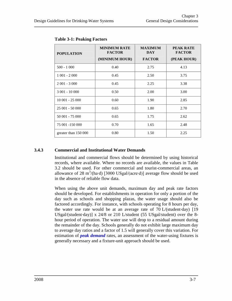
Chapter 3
Design Guidelines for Drinking-Water Systems General Design Considerations
2008 3-7
Table 3-1: Peaking Factors
POPULATION
MINIMUM RATE
FACTOR
(MINIMUM HOUR)
MAXIMUM
DAY
FACTOR
PEAK RATE
FACTOR
(PEAK HOUR)
500 - 1 000 0.40 2.75 4.13
1 001 - 2 000 0.45 2.50 3.75
2 001 - 3 000 0.45 2.25 3.38
3 001 - 10 000 0.50 2.00 3.00
10 001 - 25 000 0.60 1.90 2.85
25 001 - 50 000 0.65 1.80 2.70
50 001 - 75 000 0.65 1.75 2.62
75 001 -150 000 0.70 1.65 2.48
greater than 150 000 0.80 1.50 2.25
3.4.3 Commercial and Institutional Water Demands
Institutional and commercial flows should be determined by using historical
records, where available. Where no records are available, the values in Table
3.2 should be used. For other commercial and tourist-commercial areas, an
allowance of 28 m3/(ha∙d) [3000 USgal/(acre∙d)] average flow should be used
in the absence of reliable flow data.
When using the above unit demands, maximum day and peak rate factors
should be developed. For establishments in operation for only a portion of the
day such as schools and shopping plazas, the water usage should also be
factored accordingly. For instance, with schools operating for 8 hours per day,
the water use rate would be at an average rate of 70 L/(student·day) [19
USgal/(student·day)] x 24/8 or 210 L/student (55 USgal/student) over the 8-
hour period of operation. The water use will drop to a residual amount during
the remainder of the day. Schools generally do not exhibit large maximum day
to average day ratios and a factor of 1.5 will generally cover this variation. For
estimation of peak demand rates, an assessment of the water-using fixtures is
generally necessary and a fixture-unit approach should be used.
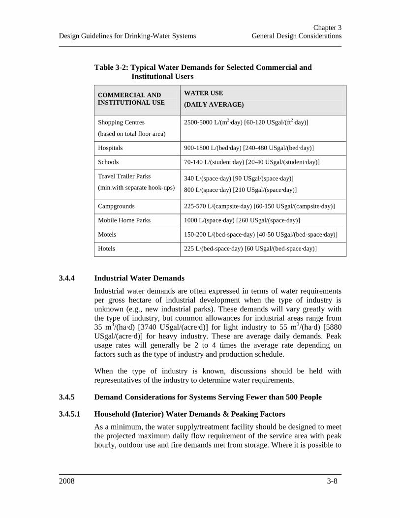
Chapter 3
Design Guidelines for Drinking-Water Systems General Design Considerations
2008 3-8
Table 3-2: Typical Water Demands for Selected Commercial and
Institutional Users
COMMERCIAL AND
INSTITUTIONAL USE
WATER USE
(DAILY AVERAGE)
Shopping Centres
(based on total floor area)
2500-5000 L/(m2·day) [60-120 USgal/(ft
2·day)]
Hospitals 900-1800 L/(bed·day) [240-480 USgal/(bed·day)]
Schools 70-140 L/(student·day) [20-40 USgal/(student·day)]
Travel Trailer Parks
(min.with separate hook-ups)
340 L/(space·day) [90 USgal/(space·day)]
800 L/(space·day) [210 USgal/(space·day)]
Campgrounds 225-570 L/(campsite·day) [60-150 USgal/(campsite·day)]
Mobile Home Parks 1000 L/(space·day) [260 USgal/(space·day)]
Motels 150-200 L/(bed-space·day) [40-50 USgal/(bed-space·day)]
Hotels 225 L/(bed-space·day) [60 USgal/(bed-space·day)]
3.4.4 Industrial Water Demands
Industrial water demands are often expressed in terms of water requirements
per gross hectare of industrial development when the type of industry is
unknown (e.g., new industrial parks). These demands will vary greatly with
the type of industry, but common allowances for industrial areas range from
35 m3/(ha·d) [3740 USgal/(acre·d)] for light industry to 55 m
3/(ha·d) [5880
USgal/(acre·d)] for heavy industry. These are average daily demands. Peak
usage rates will generally be 2 to 4 times the average rate depending on
factors such as the type of industry and production schedule.
When the type of industry is known, discussions should be held with
representatives of the industry to determine water requirements.
3.4.5 Demand Considerations for Systems Serving Fewer than 500 People
3.4.5.1 Household (Interior) Water Demands & Peaking Factors
As a minimum, the water supply/treatment facility should be designed to meet
the projected maximum daily flow requirement of the service area with peak
hourly, outdoor use and fire demands met from storage. Where it is possible to

Chapter 3
Design Guidelines for Drinking-Water Systems General Design Considerations
2008 3-9
develop the source of supply to meet more than the projected maximum daily
flow, the storage volume can be reduced accordingly.
Average daily domestic consumption rates can vary from less than 180
L/(cap·d) [48 USgal/(cap∙d)] to more than 1,500 L/(cap·d) [396
USgal/(cap∙d)]. These values represent the average flow over a 24 hour period
and do not reflect the fact that there are maximum day and peak
hour/instantaneous demands in the system each day which will exceed the
average value by a significant amount. It is essential that the source of supply
and the distribution system be capable of meeting these maximum and peak
demand rates without overtaxing the source or resulting in excessive pressure
loss in the distribution system.
In general, small systems have higher peaking factors for maximum day and
peak hour demand than large systems. The minimum rate, maximum day and
peak rate factors for the system should be based on existing flow data or data
from a similar nearby system where available. Table 3.3 provides peaking
factors for use with average day demand when actual data are not available.
Table 3-3: Peaking Factors for Drinking-Water Systems Serving Fewer
than 500 People
DWELLING
UNITS
SERVICED
EQUIVALENT
POPULATION
NIGHT
MINIMUM
HOUR
FACTOR
MAXIMUM
DAY FACTOR
PEAK
HOUR
FACTOR
10 30 0.1 9.5 14.3
50 150 0.1 4.9 7.4
100 300 0.2 3.6 5.4
150 450 0.3 3.0 4.5
167 500 0.4 2.9 4.3
3.4.5.2 Outdoor Water Use
For outdoor water use, it should be assumed that a maximum of 25% of the
homeowners could be using an outdoor tap at any one time at a rate of 20
L/min (5.3 USgpm) for one hour per day. Where fire protection is provided,
then this outdoor use need not be considered.
3.4.5.3 Fire Protection
The decision as to whether or not fire protection will be provided via the
communal water supply system is a municipal responsibility. In deciding upon
Chapter 3
Design Guidelines for Drinking-Water Systems General Design Considerations
2008 3-10
the need for such protection, the municipality should consider such factors as
the:
Availability of adequate supply of water;
Additional capital and operating costs associated with such a system;
Availability of an adequate fire department, fire service communication
and fire safety control facility; and
Alternatives to a piped communal fire facility such as residential sprinkler
systems.
For small systems, the designer should also consider that provision of fire
flow can impact residual chlorine in the distribution system due to the need
for increased pipe sizes (Section 10.1.3 – Maintaining Water Quality).
More information regarding fire protection via the communal water supply is
provided in Section 8.4 – Sizing of Storage Facilities and Section 10.1.2 – Fire
Protection.
3.4.5.4 Campgrounds
The peak water usage rates in campgrounds will vary with the type of
facilities provided (e.g., showers, flush toilets, and clothes washers) and the
ratio of these facilities to the number of campsites. A peaking factor of 4 times
average day is recommended and this factor should be applied to the average
expected water usage at full occupancy of the campground.
3.5 WATER CONSERVATION
Water conservation and efficiency measures to reduce domestic, industrial,
commercial and institutional use of water should be considered along with
efforts to estimate and reduce distribution system leakage. Simple estimates
for excessive leakage in the distribution system can be obtained by measuring
the outflow from storage. The best conditions are after rainfall, when
irrigation systems would not be operated, and between the hours of 2:00 and
4:00 a.m. when domestic water use would be at a minimum.
Where flow records or estimates for an existing distribution system suggest
that unaccounted-for-water exceeds 15% of average daily demand, then, in
consultation with the municipality/owner, an average value within the range
of 270 to 450 L/(cap·d) [70 to 120 USgal/(cap∙d)] should be considered and
the cause of the unaccounted-for-water determined and reduced/eliminated as
much as is practical. Metering of water service connections has been found to
Chapter 3
Design Guidelines for Drinking-Water Systems General Design Considerations
2008 3-11
be effective in controlling excessive water demand, and is therefore
recommended by the ministry.
The designer is reminded that, when a Permit to Take Water (PTTW) is
required, the Water Taking and Transfer Regulation (O. Reg. 387/04) made
under Section 34 of the OWRA requires that the application for the permit
document all water efficiency measures and practices that have been
undertaken or will be undertaken for the duration of the PTTW.
3.6 PLANT CAPACITY RATING
3.6.1 Design Capacity
In the case of a new municipal treatment system, a conceptual design capacity
will be developed through the Municipal Engineers Association MCEA
process and will be documented in the Environmental Study Report (ESR).
Once the ESR has met the requirements of the MCEA, this conceptual design
capacity will form the basis of detailed engineering design resulting in plans
and specifications which, in turn, will be used for obtaining a Certificate of
Approval (C of A) or a Drinking Water Works Permit (DWWP) and
Municipal Drinking Water Licence (Licence)1 from the approving Director at
the ministry. This conceptual design capacity documented in the ESR and
confirmed as the proposed rated capacity in the final design brief will be
specified in the C of A or DWWP-Licence as the rated capacity of the
approved treatment system.
In cases where an expansion, alteration or modification is required to an
existing treatment system, the proponent will need to determine the applicable
Schedule (Schedule A, B or C) of the MCEA that is relevant to the
undertaking. One of the factors in making this determination is the “existing
rated capacity” of the “existing water treatment plant” referred to in the
Schedules included in Appendix 1 of the MCEA document. This “existing
rated capacity” is the rated capacity of the treatment system specified in the
existing C of A or DWWP-Licence for the system. If a proposed undertaking
involving an expansion, alteration or modification results in treated water
flows from the treatment system to the drinking water distribution system that
would be beyond the rated capacity stated in the existing C of A or DWWP-
Licence, the expanded flow requirements must form the basis of further
MCEA considerations and subsequent detailed engineering design.
1 With the implementation of the Licensing Program, a Certificate of Approval will be replaced by the combination
of a Drinking Water Works Permit (DWWP) for the establishment or alteration of the system and a Municipal Drinking Water Licence (Licence) to authorize the use and operation of the system
Chapter 3
Design Guidelines for Drinking-Water Systems General Design Considerations
2008 3-12
3.6.2 Rated Capacity
The rated capacity of a water treatment plant is the volume of treated water
that meets all applicable Ontario drinking water quality regulations including
the aesthetic water quality objectives and that may be made available by the
water treatment plant for delivery to the drinking water distribution system in
any 24 hour period (usually provided as a rate in m³/d). Normally, it should be
equal to the projected maximum day water demand of the drinking-water
system, which is the maximum volume of water required in any 24 hour
period during the design period (usually, the next 20 years). The designer
should undertake detailed design to meet these requirements in the context of
the issues addressed in these design guidelines. The rated capacity of the
treatment system will be confirmed in the review of the design by the ministry
as part of the C of A or DWWP-Licence application review process, and will
be included in the C of A or DWWP-Licence issued after the review is
completed.
The rated capacity of a water treatment plant is essentially the net drinking
water production rate (i.e. rate of overall drinking water production minus the
sum of all in-plant losses and/or demand). The designer is encouraged to
consider the following list when determining in-plant losses and/or demand:
Maximum rate at which water may be withdrawn from the source allowed
by the PTTW. This value would take into account all water taking
required at the plant;
Ability of the water treatment plant to consistently produce drinking water
meeting all applicable Ontario drinking water regulations as well as
aesthetic water quality objectives and other identified site specific
treatment needs;
“Rated capacity” of a water treatment plant is normally distinct from “firm
capacity” (Section 7.3.1 – Firm Capacity and Station Capacity) of either
low lift or high lift pumping. The high lift pumping rate may exceed the
plant rated capacity;
Flow(s) into the treatment system and/or trains and/or stages (the gross
daily total, gross instantaneous and net instantaneous flow rates for each
individual treatment process and the overall plant);
Quantity of reject water associated with treatment processes which would
not be available for supply to the distribution system;
Chapter 3
Design Guidelines for Drinking-Water Systems General Design Considerations
2008 3-13
Worst reasonably predictable raw water quality and the periods of time it
may occur, and the highest drinking water demand during those periods,
considering the:
Number of filters out of production for backwash and rest;
Volume of water which can be treated through available process trains
(e.g. filters and disinfection contact time);
Volume of waste water (backwash water, membrane reject water,
sludge blow down, chemical make-up water, service water, and any
other in-plant treated water uses); and
Net flow available for pumping into the distribution system (treated
water minus waste water).
Available volume of the clearwell/reservoir at the water treatment plant
and its ability to balance maximum day demand with the rate of flow
(m3/d) into the clearwell; and
Rated capacity should be established by assessing potential performance
of each process in isolation and in conjunction with the entire process train
operating as a system to identify the treatment rate of its slowest unit
operation – the rate controlling step.
Notwithstanding the above, there could be circumstances where the treatment
system has been designed to accommodate, and the C of A or DWWP-
Licence may specify, multiple treatment system rated capacities under
specified conditions. For example, the capacity of a conventional or
membrane filtration plant could have one rating for summer temperatures and
a lower rating for winter temperatures. A chlorine contact process could also
be a temperature-based rate controlling step with winter flows limited by the
CT which can be achieved under cold water conditions. In such cases of
multiple specified capacities, the C of A or DWWP-Licence will also specify
which of these should be considered the nominal rated capacity for purposes
of the MCEA process.
The rated capacity as established in the final design brief would be based on a
combination of treatment processes and their performance, including
allowances for downtime and redundancy. The designer should document the
proposed capacity of each process along with the engineering and water
quality parameters on which this capacity is based.
The water treatment plant rated capacity, as defined in the final design brief
and subsequently in the C of A, or DWWP-Licence is a point-in-time value.
Improvements to operational knowledge and technology, and changes to
Chapter 3
Design Guidelines for Drinking-Water Systems General Design Considerations
2008 3-14
source water quality and physical facility condition can impact the rated
capacity of the plant.
3.6.3 Hydraulic Capacity
The overall water treatment plant hydraulics should be designed for more than
the gross flow rates. The designer should consider the sizes of physical
hydraulic restrictions (channels, gates, valves, openings, pipe sizes) and
consider increasing their hydraulic capacity by 50% over gross flow rates.
Equipment and/or provisions should be included in the design so that in the
future if process innovations occur, the design would allow the higher flow
rate by implementing low cost modifications to the existing plant.
3.7 SITE SELECTION CRITERIA
Municipal water projects are subject to the MCEA and the site selection
should be planned according to the requirements of the MCEA, including an
evaluation of technical, social, historical/archaeological, natural environment
and economic criteria. Whether for municipal or non-municipal facilities,
factors which should be considered when selecting a site for new treatment
works or the extension of an existing facility include:
Adequacy of separation from residential areas or other non-compatible
land uses;
Optimum location of the plant with regard to the location of the raw water
source and the area to be serviced;
Susceptibility of the site to flooding;
Suitability of subsurface and soil conditions;
Adequacy of the site for future expansion;
Minimizing adverse environmental impact both during construction and
operation of the facility;
Avoidance of construction adjacent to a shore line except where
unavoidable, since suitable measures would be necessary to prevent
erosion, and to protect structures from potential wave action or ice-piling;
and
Waste disposal considerations.
Information pertaining to water source selection is provided in Chapter 4 –
Source Development.
Chapter 3
Design Guidelines for Drinking-Water Systems General Design Considerations
2008 3-15
3.8 PLANT/ BUILDING LAYOUT
The general arrangement within the selected site should take into
consideration the suitability of subsurface conditions to provide the necessary
facilities at minimum cost. Where possible, the designer should take
advantage of natural grades in arranging the various process units.
Consideration may be given to the use of inter-stage transfer pumps where
they are more economical (capital and operating) than extensive construction
in adverse ground such as rock.
In the layout of the plant, the designer should locate the buildings to allow
adequate flexibility for the economical expansion of the various treatment
sections, as well as plant waste treatment and disposal facilities. Plant layout
should consider making best advantage of prevailing wind and weather
conditions to minimize energy consumption, for example, locating units
which need only moderate temperatures on northern exposures.
Plant design should consider functional aspects of the plant layout, access
roads, access to the power grid, site grading, site drainage, walks, driveways
and chemical delivery and receiving areas. The plant design should also
incorporate spill control features for bulk chemical off-loading areas.
Roadways for chemical deliveries should be designed to be sufficient to
accommodate the largest anticipated delivery [typically a 27,000 L (7,132
USgal) tank truck], with allowance made for vehicle turning and forward exit
from the site. Roadways should be designed for truck traffic in accordance
with the Ontario Ministry of Transportation Ontario Provincial Standards for
Roads and Public Works (OPS).
The design of the building layout should provide for adequate ventilation,
lighting, heating and drainage, dehumidification equipment, accessibility of
equipment for operation, servicing and removal, flexibility of operation, and
operator safety. The plant layout should also allow for the probability of snow
drifting, and entrances and roadways should be located to minimize the effect
of snow drifting on operations.
Plant designers should also consider all aspects of plant security and layouts
that protect critical areas from vandalism or sabotage.
Within the constraints mentioned above, the designer should prepare a plant
layout where the various processing units are arranged in a logical progression
to avoid the necessity for major pipelines or conduits to transmit water from
one module to the next, and also to arrange the plant layout to provide
convenience of operation, accessibility of equipment for servicing and
removal, as well as to ensure operator safety. Whenever possible, the process
Chapter 3
Design Guidelines for Drinking-Water Systems General Design Considerations
2008 3-16
units should be located adjacent to each other to minimize the use of space
and materials, and to minimize travel distances for maintenance crews. The
plant layout should provide adequate protection for all treated water units. The
design should include chemical storage and feed equipment in separate
room(s) to reduce hazards and dust problems. Chemical storage should be
designed for full spill containment and be separate from process structures to
ensure that any spills or structural failures for chemical systems will not
impact any process streams.
The designer should review all of the above considerations regarding
plant/building layout with both the municipality/owner and certified operator
at an early stage of the planning and design.
3.9 HYDRAULICS
The design of a new water treatment plant should take into consideration the
existing and proposed hydraulic grade lines to determine if raw or treated
water pumping will be required. The use of gravity flow can often result in
lower capital and operating costs, but may restrict the siting of the treatment
facility and may not be suitable for use with some treatment processes. Such
factors should be carefully considered to determine the best possible hydraulic
and siting configuration such that the treated water quality objectives of the
facility are fully met (Section 3.6.3 – Hydraulic Capacity).
3.10 ELECTRICAL COMPONENTS
All electrical work should conform to the requirements of the Canadian
Electrical Code (CSA C22.1-06) and to relevant provincial and/or local codes.
Main switch gear electrical controls should be located above grade in areas
not subject to flooding. The designer should consider switchgear facility
sizing requirements if variable frequency drive (VFD) type equipment is to be
employed.
Consideration should be given to providing voltage stabilization in the
electrical services to laboratory and/or sensitive process control equipment,
since a relatively constant voltage may be required for proper operation.
3.11 INSTRUMENTATION & CONTROL
Instrumentation and controls should be provided to allow safe and efficient
operation of all parts of the drinking water treatment plant and the associated
distribution system (Chapter 9 – Instrumentation and Control).
Chapter 3
Design Guidelines for Drinking-Water Systems General Design Considerations
2008 3-17
3.12 STANDBY POWER
The need for standby power and the extent of equipment requiring operation
by standby power should be individually assessed for each water treatment
plant and water distribution system. A plan should be developed to ensure that
average day demand can be met during a power outage, and that at least an
emergency level of lighting and process control operations can be maintained.
The plan should take into account the availability of storage capacity in the
distribution system (elevated or ground-level storage with standby power).
Some of the factors which should be considered in making the decisions
regarding standby power and the process units to be operated by the standby
power equipment are as follows:
Frequency and length of power outages in the area;
Reliability of primary power source (number of power feeder lines
supplying grid system, number of alternate routes within the grid system,
and number of alternate transformers through which power could be
directed to the water treatment plant);
Available treated water storage within the system;
Type of water storage (underground or elevated);
Requirements for fire protection;
Type of standby power; and
Lower level of emissions provided by alternative fuel technologies.
Depending on the complexity of the plant, standby power may or may not be
provided for auxiliary services such as lighting, instrumentation and control.
In consultation with the municipality/owner, the designer should consider
what critical equipment should be operated from the emergency power system
to maintain water quality integrity during a power outage.
The designer should be aware that a sustained loss of water supply that allows
reservoirs to empty represents a significant risk to public health. As a
distribution system dewaters due to continuous water demand, negative or
atmospheric pressures are induced, starting at the higher elevations. This
creates the potential for uncontrolled backflow, e.g., garden hoses connected
to open faucets and an environment in which any exfiltration from a leaky
distribution system becomes infiltration, drawing in untreated groundwater.
Chapter 3
Design Guidelines for Drinking-Water Systems General Design Considerations
2008 3-18
This is even more acute for direct-pressure systems (i.e., systems without on-
line storage).
In designing generator systems, the designer should consider the efficient
operation of the engines and whether the plant is staffed at all times or is
unattended. Timers should be provided to bring equipment on-line in such a
way that the generators are not overloaded by the starting current
requirements of motors. Similar protection is necessary to avoid overload of
the normal electrical supply on resumption of power following a power
failure.
The standby power equipment should be located so that it fits conveniently
into the electrical distribution system of the plant. Under some circumstances,
it may be preferable to locate the generator set remote from the treatment
plant in a separate building to satisfy air and noise requirements under the
Environmental Protection Act (EPA). Self-contained generator sets that can be
pad mounted externally may also be considered.
Engine cooling water may not be returned to any process units. Where cooling
water is discharged to a storm sewer system, the designer should ensure that
the storm sewer system has adequate capacity, or an alternate diversion of
cooling water will be required.
Generator units should be mounted on a pad and surrounded by a containment
system to retain any fuel spills. Generator units or fuel storage should not be
located above any water treatment process unit or raw or treated water
reservoir to avoid any chance of contamination. A clear space for inspection
and servicing not less than 1m (3 ft) on all sides of the unit should be
provided.
Internal combustion engines used to drive auxiliary pumps, service pumps
through special drives, or electrical generating equipment should be located
above grade with adequate ventilation of fuel vapours and exhaust gases.
Carbon monoxide detectors are recommended where fuel-fired generators are
housed.
The designer should refer to the applicable Technical Standards and Safety
Authority (TSSA) standards for requirements associated with the safe storage,
handling and use of hydrocarbon fuels (such as gasoline, diesel, propane and
natural gas).
3.12.1 Diesel Fuel Storage
Sufficient fuel storage should be provided, taking into account the historical
data on length of power outages in the area, and any weather or other
Chapter 3
Design Guidelines for Drinking-Water Systems General Design Considerations
2008 3-19
conditions which might prevent deliveries of fuel. A minimum 500 L (132
USgal) storage should be provided for generator set capacities up to 25 kW
and 1,000 L (264 USgal) storage for generator set capacities from 30 to 100
kW.
Either underground or inside fuel storage tanks may be used. Factors such as
corrosion potential, leakage and spill protection, storage volume needed and
need for fuel pumps should be evaluated. Fuel storage tanks should not be
located above any water reservoir or clearwell. The design of fuel storage
tanks and supply lines must conform to all applicable federal and provincial
legislation and regulations.
3.13 EMISSIONS OF CONTAMINANTS TO AIR
For all sources of emission of contaminants to the air from drinking-water
facilities (e.g., gases from air striping processes, exhaust emissions and noise
of diesel generators, and noise of air blowers or compressors) the
requirements of Section 9 of the Environmental Protection Act (EPA) need to
be satisfied.
The Air Pollution - Local Air Quality regulation (O. Reg. 419/05), under the
EPA, specifies the maximum allowable concentration of specific air
contaminants at the point of impingement. Compliance is achieved by
maintaining the point of impingement concentrations of the contaminants
discharged from the source of emission below the maximum concentrations
stipulated in the regulation. Typical points of impingement are the property
line and all critical receptors, such as building air intakes or windows.
3.14 PERSONNEL FACILITIES
The personnel facilities needed will be largely dictated by the number and
gender of operating staff required and the time periods during which the plant
is staffed. As a minimum, it is recommended that provisions be made for
storage lockers, preferably two for each employee (one for work clothes, one
for clean clothes), and change rooms/washrooms with showers. Water
efficient fixtures should be used. A lunch room of adequate size to serve as a
meeting or training room for plant staff and a suitable office for plant
supervisory staff and record keeping should be provided. Whenever possible,
these personnel facilities should be separated from the plant facilities, but with
convenient access to the plant.
Drinking water service to most buildings should be provided. Refer to Section
3.20.4 – Backflow Prevention/ Cross-Connection Control in this chapter for
information regarding backflow prevention.
Chapter 3
Design Guidelines for Drinking-Water Systems General Design Considerations
2008 3-20
The provision of drinking water and sanitary facilities for operators may lead
to a significant increase in cost for small remote plants. In communities where
such facilities may be available elsewhere, the designer should consult with
the municipality/owner to determine whether such facilities are required.
3.15 BUILDING SERVICES
All building services should conform to the applicable codes.
Adequate and safe heating systems with controls should be provided. In many
areas of the plant, sufficient heat need only be provided to prevent freezing of
equipment or treatment processes. Buildings should be well ventilated by
means of windows, doors, roof ventilators or other means. All rooms,
compartments, pits and other enclosures below grade which must be entered
should have adequate forced ventilation provided when it is necessary to enter
them. Rooms and galleries containing equipment or piping should be
adequately heated, ventilated, and dehumidified to prevent excessive
condensation. Switches should be provided for convenient control of the
forced ventilation.
Buildings should be adequately lighted throughout by means of natural light
and artificial lighting. Control switches should be conveniently placed at each
entrance to each room or area. Emergency lighting should be provided.
Communications systems should be provided including connections between
buildings.
Power outlets of suitable voltage should be provided at convenient spacing
through plant buildings to provide power for purposes such as maintenance
equipment and extension lighting. Power outlets located on the outside of
buildings may be advantageous. Ground fault interrupter (GFI) type outlets
are desirable throughout (where appropriate). Outlets supplied by
uninterruptible power supply (UPS) or emergency power systems should be
located such that they are easily accessible during a power outage.
Adequate shop space and storage for the designed facilities should be
provided. A bridge crane, monorail, lifting hooks, hoist or other adequate
facilities should be provided for servicing or removing heavy and/or large
equipment.
3.16 SAMPLING & MONITORING EQUIPMENT
Regulatory monitoring requirements are described in the Drinking-Water
Systems regulation (O. Reg. 170/03) under the Safe Drinking Water Act, 2002,
as well as the Disinfection Procedure. Smooth-nosed sampling tap(s) should
Chapter 3
Design Guidelines for Drinking-Water Systems General Design Considerations
2008 3-21
be provided for collection of water samples for both bacteriological and
chemical analyses. The sample tap(s) should be easily accessible and located
in an area that can be maintained in a sanitary condition. Sample withdrawal
lines should be located to provide samples that are representative of the
composition of the whole process stream at that point. Sample lines should be
stainless steel from the sampling point to the sampling tap. Provisions for
back-flushing or cleaning should be made available. The basic sampling
locations in a water treatment plant are: raw water prior to any chemical
addition; effluent from specific process unit(s); residuals streams; treated
water to be delivered to the distribution system. In certain instances, it may be
necessary to provide “intermediate” sampling points in a process unit.
On-line process monitoring is discussed in Section 9.4 – Monitoring.
Additional equipment to monitor the process is described in the following
section.
3.17 LABORATORY FACILITIES
Each drinking-water system should have its own equipment and sufficient
facilities for routine laboratory testing necessary to ensure proper operation
and process control of the system. Laboratory equipment selection should be
based on the characteristics of the raw water source and the complexity of the
treatment processes involved. Laboratory test kits which simplify procedures
for one or more tests may be acceptable. Methods for verifying adequate
quality assurances and for routine calibration of equipment should be
provided. A certified operator or water quality analyst qualified to perform the
necessary laboratory tests is essential; tests which may be performed by a
certified operator or water quality analyst are controlled by the Drinking-
Water Testing Services Regulation (O. Reg. 248/03) under the Safe Drinking
Water Act, 2002.
Analyses conducted to determine compliance with drinking water regulations
must be performed in a drinking water testing laboratory that is licensed under
Part VIII of SDWA for classes of parameters indicated.
Sample lines may be used to convey a continuous sample stream to the
laboratory from the various stages of the treatment process, for example, raw
water, settled water, filtered water and treated water, but not flocculated
water. These sample lines should run continuously to provide representative
samples and be kept as short as possible. In more remote systems a continuous
flow can represent a significant wastewater issue. Where continuous flows are
required or are being considered, the designer should also consider carefully
how the wastewater will be disposed.

Chapter 3
Design Guidelines for Drinking-Water Systems General Design Considerations
2008 3-22
Smooth-nosed sampling tap(s) should be provided. Stainless steel sample lines
from the sampling point to the tap are recommended.
3.17.1 Testing Equipment
As a minimum, the following laboratory equipment should be provided:
Water treatment plants that chlorinate must have test equipment for
determining free and total residual chlorine (O. Reg. 170/03);
All water treatment plants should have a bench or portable nephelometric
turbidimeter;
Each water treatment plant using coagulation, including those which lime
soften, should have a pH meter, titration equipment for both hardness and
alkalinity, jar test equipment to aid in establishing the optimum coagulant
dosage for changing water conditions and test equipment for measuring
residual aluminum or iron (depending on the coagulant used);
Each ion-exchange softening plant and lime softening plant treating only
groundwater should have a pH meter and titration equipment for both
hardness and alkalinity;
Each iron and/or manganese removal plant should have test equipment
capable of accurately measuring iron to a minimum of 0.01 mg/L, and/or
test equipment capable of accurately measuring manganese to a minimum
of 0.005 mg/L;
Water supplies which fluoridate should have test equipment for
determining fluoride;
Water supplies which feed poly and/or orthophosphates should have test
equipment capable of accurately measuring phosphates from 0.1 to 5
mg/L;
Where the process treatment involves reduction of raw water colour,
equipment should be provided to determine both true and apparent colour
in the raw water and treated water quality ranges; and
Where UV treatment is used, ready access to a UV meter capable of
measuring transmission of 254 nm wavelength light through a path length
of 1 cm (0.4 in) of water to an accuracy within +/-2% should be provided.
Sufficient glassware and general reagents should be provided to conduct all
the required analyses, as well as appropriate cleaning agents. Sample and
reagent storage and refrigeration should also be provided.
Chapter 3
Design Guidelines for Drinking-Water Systems General Design Considerations
2008 3-23
3.17.2 Physical Facilities
Sufficient bench space, adequate ventilation, adequate lighting, storage room,
laboratory sink, and auxiliary facilities should be provided. Air conditioning
may be necessary.
The minimum linear bench space should be 3 m (10 ft), including a wash-up
sink. Where space is available, or the size of the laboratory permits, the space
should be divided into “dry” and “wet” areas so that sensitive equipment is
not subjected to undesirable conditions.
At larger treatment plants, the designer should consider providing pilot-scale
facilities, with sufficient flexibility to alter coagulation, flocculation, filtration
and other process operations, to assist in determining optimum plant operating
conditions. If a pilot plant is not currently being considered, space for future
addition should be provided.
3.18 FLOW METERING
All drinking-water systems should have flow measuring devices to measure
the flow from each source (well or surface water intake) and conveyed to and
through the water treatment plant, the flow of any blended water of different
quality and the flow of treated water supplied to the distribution system. In
addition, flow through unit processes, backwash flow, chemical and gas flows
should be metered for monitoring and controlling the treatment process
(Section 9.4 – Monitoring).
The designer should consider the importance of meter accuracy, specifically
as it relates to compliance with Approval/DWWP-Licence conditions.
In addition, design considerations for flow measuring equipment include:
Parts in contact with drinking water should be easy to clean and disinfect
(Section 3.26 – Chemicals and Other Water Contacting Materials);
Parts in contact with fluids should be suitable for the conditions, including
aggressive chemicals or solids that can cause abrasion;
Instruments should be compatible with the environment in which they are
located (e.g., high humidity, temperature, outdoors, and electromagnetic
interference);
Instruments should be located so that they provide accurate and reliable
data (e.g., straight pipe requirements upstream and downstream) according
to the manufacturer specifications;

Chapter 3
Design Guidelines for Drinking-Water Systems General Design Considerations
2008 3-24
Convenient access to the instrument for maintenance and calibration
should be provided. Isolation should be provided so that an instrument can
be removed and serviced or replaced. A bypass, pipe spool piece or
standby unit should be provided if servicing or calibration will disrupt
production;
Instruments should include a local display;
Instruments should be selected to provide reliable data over the entire
range required; the turndown of the instrument should be considered in
instrument selection. The accuracy and precision required for the process
should also be considered (cost generally increases as accuracy increases);
and
Lifecycle cost, including maintenance and calibration requirements and
hydraulic head loss (pumping costs), should be considered.
The main process flows are usually measured using mass flowmeters,
magnetic, ultrasonic or differential pressure (e.g., venturi) flowmeters. Where
low head loss is required, magnetic or ultrasonic meters are preferred.
Rotameters are suitable for small flows of liquids and gases. Table 3.4
provides some characteristics of commonly-used flowmeters.
3.19 FACILITY DRINKING WATER SUPPLY
The facility drinking water supply service line should be supplied from a
source of treated water at a point downstream of all treatment process units
and disinfectant contact time. There should be no cross-connections between
the facility drinking water supply service line and any piping, troughs, tanks
or other treatment units containing wastewater, treatment chemicals, or raw or
partially treated water. .
3.20 IN-PLANT PIPING
3.20.1 General
All piping used in water treatment plants should be manufactured in
accordance with AWWA or CSA standards. Material selection will depend
upon economic and corrosion rate factors, as well as the type of equipment
used and connections required. The designer should be aware of the greater
potential for deflection in thin wall pipe systems than in other systems. Refer
to Section 3.26 – Chemicals and Other Water Contacting Materials for more
information on materials contacting drinking water.
In the design of the piping, allowance should be made for future capacities
and also the ease of extending the piping without major disturbance to the
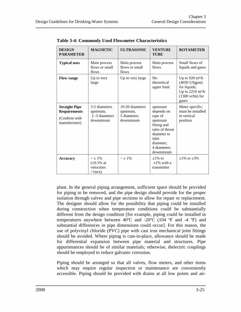
Chapter 3
Design Guidelines for Drinking-Water Systems General Design Considerations
2008 3-25
Table 3-4: Commonly Used Flowmeter Characteristics
DESIGN
PARAMETER
MAGNETIC ULTRASONIC VENTURI
TUBE
ROTAMETER
Typical uses Main process
flows or small
flows
Main process
flows or small
flows
Main process
flows
Small flows of
liquids and gases
Flow range Up to very
large
Up to very large No
theoretical
upper limit
Up to 920 m³/h
(4050 USgpm)
for liquids;
Up to 2210 m³/h
(1300 scfm) for
gases
Straight Pipe
Requirements
(Confirm with
manufacturer)
3-5 diameters
upstream,
2 -3 diameters
downstream
10-20 diameters
upstream,
5 diameters
downstream
upstream
depends on
type of
upstream
fitting and
ratio of throat
diameter to
inlet
diameter;
4 diameters
downstream
Meter specific;
must be installed
in vertical
position
Accuracy ~ ± 1%
(±0.5% at
velocities
>1m/s)
~ ± 1% ±1% to
±2% with a
transmitter
±1% to ±3%
plant. In the general piping arrangement, sufficient space should be provided
for piping to be removed, and the pipe design should provide for the proper
isolation through valves and pipe sections to allow for repair or replacement.
The designer should allow for the possibility that piping could be installed
during construction when temperature conditions could be substantially
different from the design condition [for example, piping could be installed in
temperatures anywhere between 40ºC and -20ºC (104 ºF and -4 ºF) and
substantial differences in pipe dimensions could occur]. For this reason, the
use of polyvinyl chloride (PVC) pipe with cast iron mechanical joint fittings
should be avoided. Where piping is cast-in-place, allowance should be made
for differential expansion between pipe material and structures. Pipe
appurtenances should be of similar materials; otherwise, dielectric couplings
should be employed to reduce galvanic corrosion.
Piping should be arranged so that all valves, flow meters, and other items
which may require regular inspection or maintenance are conveniently
accessible. Piping should be provided with drains at all low points and air-
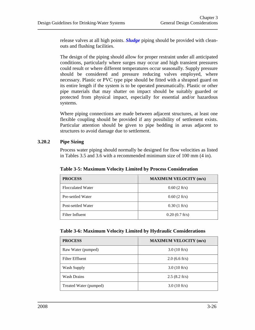
Chapter 3
Design Guidelines for Drinking-Water Systems General Design Considerations
2008 3-26
release valves at all high points. Sludge piping should be provided with clean-
outs and flushing facilities.
The design of the piping should allow for proper restraint under all anticipated
conditions, particularly where surges may occur and high transient pressures
could result or where different temperatures occur seasonally. Supply pressure
should be considered and pressure reducing valves employed, where
necessary. Plastic or PVC type pipe should be fitted with a shrapnel guard on
its entire length if the system is to be operated pneumatically. Plastic or other
pipe materials that may shatter on impact should be suitably guarded or
protected from physical impact, especially for essential and/or hazardous
systems.
Where piping connections are made between adjacent structures, at least one
flexible coupling should be provided if any possibility of settlement exists.
Particular attention should be given to pipe bedding in areas adjacent to
structures to avoid damage due to settlement.
3.20.2 Pipe Sizing
Process water piping should normally be designed for flow velocities as listed
in Tables 3.5 and 3.6 with a recommended minimum size of 100 mm (4 in).
Table 3-5: Maximum Velocity Limited by Process Consideration
PROCESS MAXIMUM VELOCITY (m/s)
Flocculated Water 0.60 (2 ft/s)
Pre-settled Water 0.60 (2 ft/s)
Post-settled Water 0.30 (1 ft/s)
Filter Influent 0.20 (0.7 ft/s)
Table 3-6: Maximum Velocity Limited by Hydraulic Considerations
PROCESS MAXIMUM VELOCITY (m/s)
Raw Water (pumped) 3.0 (10 ft/s)
Filter Effluent 2.0 (6.6 ft/s)
Wash Supply 3.0 (10 ft/s)
Wash Drains 2.5 (8.2 ft/s)
Treated Water (pumped) 3.0 (10 ft/s)

Chapter 3
Design Guidelines for Drinking-Water Systems General Design Considerations
2008 3-27
3.20.3 Piping Identification Requirements
The Industrial Establishments regulation (R.R.O 1990, Regulation 851) under
the Occupational Health and Safety Act (OHSA), makes piping identification,
as to contents and flow direction, mandatory for piping systems containing
hazardous substances. Identification should comply with the requirements of
Canadian General Standards Board (CGSB) standard CAN/CGSB 24.3-92
Identification of Piping Systems2 to simplify operation and maintenance
procedures and improve safety. Under this standard, pipes are identified by
background, legend, and pictogram colour.
The background and legend, and pictogram colours and code numbers used to
identify materials contained in a piping system are provided in Tables 3-7 and
3-8. The code numbers are from CGSB 1-GP-12c Standard Paint Colours,
Part 1 Colour Identification and Selection. Piping may be identified by paint,
decals, plastic bands, or polyethylene or detectable ribbon.
Table 3-7: Piping Identification – Background and Legend Colour
CONTENTS
CLASSIFICATION
BACKGROUND COLOUR LEGEND COLOUR
Colour CGSB
Equivalent* Colour
CGSB
Equivalent*
Hazardous Yellow 505-101 Black 512-101
Inherently Low Hazard Green 503-107 White 513-101
Fire protection Red 509-102 White 513-101
* Colour numbers are those in CGSB standard 1-GP-12
Where there is no previously existing standard colour code, it is suggested that
the guidelines in Tables 3.9, 3.10 and 3.11 be used. Where alternative
chemicals are used, it is suggested that a coherent code be developed which
consistently identifies the degree of hazard associated with the material
contained in the pipe.
3.20.4 Backflow Prevention/ Cross-Connection Control
Within a water treatment plant, considerable potential exists for cross-
connections between drinking and non-drinking waters. Typical examples are
drinking water supplies for chemical solution make-up, cooling water supplies
to mechanical equipment, seal water supplies to pumps and filter surface-wash
piping. While pump seal water supplies need only be of better sanitary quality
2 The CAN/CGSB 24.3-92 document is not up-to-date and this matter is currently under review.
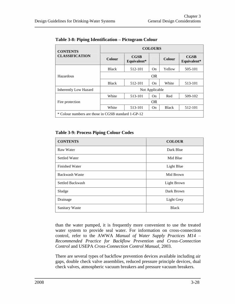
Chapter 3
Design Guidelines for Drinking-Water Systems General Design Considerations
2008 3-28
Table 3-8: Piping Identification – Pictogram Colour
CONTENTS
CLASSIFICATION
COLOURS
Colour CGSB
Equivalent* Colour
CGSB
Equivalent*
Hazardous
Black 512-101 On Yellow 505-101
OR
Black 512-101 On White 513-101
Inherently Low Hazard Not Applicable
Fire protection
White 513-101 On Red 509-102
OR
White 513-101 On Black 512-101
* Colour numbers are those in CGSB standard 1-GP-12
Table 3-9: Process Piping Colour Codes
CONTENTS COLOUR
Raw Water Dark Blue
Settled Water Mid Blue
Finished Water Light Blue
Backwash Waste Mid Brown
Settled Backwash Light Brown
Sludge Dark Brown
Drainage Light Grey
Sanitary Waste Black
than the water pumped, it is frequently more convenient to use the treated
water system to provide seal water. For information on cross-connection
control, refer to the AWWA Manual of Water Supply Practices M14 –
Recommended Practice for Backflow Prevention and Cross-Connection
Control and USEPA Cross-Connection Control Manual, 2003.
There are several types of backflow prevention devices available including air
gaps, double check valve assemblies, reduced pressure principle devices, dual
check valves, atmospheric vacuum breakers and pressure vacuum breakers.

Chapter 3
Design Guidelines for Drinking-Water Systems General Design Considerations
2008 3-29
Table 3-10: Chemical Piping Colour Codes
MATERIAL PRIMARY
COLOUR
SECONDARY
COLOUR
Aluminum Sulphate Light Green -
Ferric Chloride Light Green Orange
Silicate Compounds Light Green White
Polyelectrolytes Light Green Grey
Chlorine Gas* Yellow -
Sodium/Calcium Hypochlorite Solution Yellow White/Red
Chlorine Dioxide Solution Yellow Orange
Lime White Orange
Sodium Carbonate White Grey
Sodium Bicarbonate White Yellow
Carbon Dioxide* White -
Alkali Hydroxide White Red
Sulphuric Acid Orange Red
Sulphur Dioxide* Orange -
Ozone* Brown -
Potassium Permanganate Purple -
Fluoride Chemicals Purple Red
Ammonia* Bright Blue -
Flammable Gas Red -
* All gas solution lines to have light blue secondary.
For applications involving health hazards, only air gaps or reduced pressure
principle devices should be used.
For information on backflow prevention equipment, refer to:
Applicable municipal by-laws;

Chapter 3
Design Guidelines for Drinking-Water Systems General Design Considerations
2008 3-30
Table 3-11: Colour Code Numbers for Process and Chemical Piping
COLOUR CGSB EQUIVALENT*
Grey 501-103
Light-Grey 501-108
Dark-Blue 502-103
Bight-Blue 502-104
Light-Blue 502-106
Mid-Blue 502-208
Light-Green 503-323
Dark-Brown 504-102
Brown 504-105
Mid-Brown 504-107
Yellow 505-101
Light-Brown 505-206
Orange 508-102
Red 509-102
Purple 511-101
Black 512-101
White 513-101
* Colour numbers are those in CGSB standard 1-GP-12
Part 7 of Division B of the Building Code (O. Reg. 350/06) under the
Building Code Act 1992;
CAN/CSA-B64 SERIES-01 Backflow Preventers and Vacuum Breakers,
CAN/CSA-B64.10-01/B64.10.1-01 Manual for the Selection and
Installation of Backflow Prevention Devices/Manual for the Maintenance
and Field Testing of Backflow Prevention Devices, and CAN/CSA-
B64.10S1-04/B64.10.1S1-Supplement #1 to CAN/CSA-B64.10-
01/CAN/CSA-B64.10.1-01;
AWWA Standard C510: Double Check Valve Backflow Prevention
Assembly and AWWA Standard C511: Reduced-Pressure Principle
Backflow Prevention Assembly; and
Chapter 3
Design Guidelines for Drinking-Water Systems General Design Considerations
2008 3-31
AWWA Manual of Water Supply Practices M14 – Recommended Practice
for Backflow Prevention and Cross-Connection Control.
3.21 DISINFECTION AFTER CONSTRUCTION OR REPAIRS
All wells, pipes, tanks and equipment which can convey or store drinking
water should be disinfected in accordance with AWWA Standard C650-series
(Disinfection of Facilities) before being placed into operation after
construction, maintenance or repairs as required by the Procedure for
Disinfection of Drinking Water in Ontario (Disinfection Procedure). Plans or
specifications should outline the procedure and include the disinfectant
dosage, contact time and method of testing the efficacy of the procedure.
3.22 MANUALS & TRAINING
3.22.1 Operations Manual
An operations manual should be supplied to the water works as an essential
part of the design. The operations manual should include detailed descriptions
and explanations of the treatment process and operational strategies for
meeting the requirements of O. Reg. 170/03 and the Disinfection Procedure.
All standard operating procedures developed for the plant should be included
in the operations manual. The manual should be provided in standard
electronic form and cover the following topics:
A plant overview and process control philosophy statement;
Detailed unit operations and chemical dosing for normal operation and
emergency situations;
Simplified system schematics that take into account the spatial
relationships involved;
Storage and transmission descriptions and operational procedures;
Descriptions and operational procedures for facility utilities (HVAC, plant
service water, security);
General safety information, including provisions to keep up-to-date
Material Safety Data Sheets (MSDS) as set out under the federal
Hazardous Products Act and associated Controlled Products Regulations;
Spill containment and emergency procedures;
Emergency power systems and electrical system operation;
Chapter 3
Design Guidelines for Drinking-Water Systems General Design Considerations
2008 3-32
Security of infrastructure, treated water, electronic files and/or programs
and response procedures to breaches or intrusions;
Applicable regulations;
Monitoring, reporting and documentation procedures;
Disinfection procedures for bringing equipment on-line after maintenance;
Reliability and redundancy analysis of system components;
Detailed routine maintenance procedures;
Alarm notifications and response procedures;
A list of emergency contacts and locations of contingency plans; and
A list of major equipment suppliers.
3.22.2 Equipment Manuals
Equipment manuals including parts lists and parts order forms, operator safety
procedures and an operational troubleshooting section should be supplied to
the municipality/owner as part of any proprietary unit installed in the facility.
3.22.3 Training
Provisions should be made for operator instruction at the start-up of any new
facility, equipment or process, with full documentation.
3.23 SAFETY
Consideration must be given to the safety of water plant personnel and
visitors. The designer should refer to all applicable safety codes and
regulations, including the Occupational Health and Safety Act (OSHA),
Building Code (O. Reg. 350/06) under the Building Code Act, 1992 and Fire
Code (O. Reg. 388/97) under the Fire Protection and Prevention Act, 1997.
Items to be considered include noise arresters, noise protection, confined
space entry, protective equipment and clothing, ergonomics, gas masks, safety
showers and eye washes, handrails and guards, ladders, warning signs, smoke
detectors, toxic gas detectors and fire extinguishers.
Equipment and chemical suppliers should also be contacted regarding
particular hazards of their products and the appropriate steps taken in the
facility design to ensure safe operation.
Chapter 3
Design Guidelines for Drinking-Water Systems General Design Considerations
2008 3-33
3.24 SECURITY
Design measures to ensure the security of the drinking-water system should be
incorporated, installed and instituted. Such measures, as a minimum, should
include means to lock all exterior doorways, windows, gates and other
entrances to source, treatment and water storage facilities. Other measures
may include fencing, signage, closed-circuit monitoring, real-time water
quality monitoring and intrusion alarms.
3.25 FLOOD PROTECTION
Other than surface water intakes, all water supply facilities and water
treatment plant access roads should be protected to at least the 100 year flood
elevation or maximum flood of record.
3.26 CHEMICALS & OTHER WATER CONTACTING MATERIALS
All chemical additives and water contacting materials used in the construction
and operation of drinking-water systems should meet all applicable quality
standards set by AWWA and, in addition, the consumer safety standards
NSF/ANSI3 Standard 60: Drinking Water Treatment Chemicals - Health
Effects and NSF/ANSI Standard 61: Drinking Water System Components -
Health Effects. For uncertified water contacting materials that have been in
common and traditional use, such as cement mortar lining or water pipe
meeting AWWA specifications, the NSF/ANSI safety certification may not be
necessary.
The designer should be aware of the standard condition imposed on
Approvals/DWWP-Licences for municipal residential drinking-water systems
making the above recommendation a requirement for such systems with the
following exceptions:
Water pipe and pipe fittings meeting AWWA specifications made from
ductile iron, cast iron, PVC, fibre and/or steel wire reinforced cement pipe
or high density polyethylene (HDPE);
Articles made of stainless steel, glass, HDPE or Teflon®;
Cement mortar for watermain lining and for water contacting surfaces of
concrete structures made from washed aggregates and Portland cement;
Food grade oil and lubricants; and
3 In Ontario, certification of conformance to NSF/ANSI standards may be provided by one of the agencies approved for this purpose by the Standards Council of Canada.
Chapter 3
Design Guidelines for Drinking-Water Systems General Design Considerations
2008 3-34
Any other material or chemical where the municipality/owner has written
documentation signed by the Director that indicates that the ministry is
satisfied that the chemical or material is acceptable for use within the
drinking-water system and that the chemical or material is only used as
permitted by the documentation.
3.27 WATER TREATMENT PLANT RESIDUALS & SANITARY WASTE
The nature and treatability of the waste residuals to be produced as a result of
the treatment processes should be adequately characterized. Waste
characterization, in addition to the ultimate disposal requirements, should be
given a high degree of consideration in the planning and selection of water
treatment processes. Methods of reducing process residual volumes should be
considered (Chapter 11 – Residuals Management).
All sanitary wastes from water treatment plants, pumping stations, and other
water works should be discharged to a sanitary sewer system, a subsurface
sewage disposal system or to a sewage treatment facility providing suitable
treatment. Sanitary wastes should be kept separate from all process residuals
to avoid the need for treatment of all plant residuals in the same manner as
sanitary wastes.
3.28 ENERGY CONSERVATION
Typically, the highest energy expenditures in water treatment plants result
from high lift pumping. Minimizing energy consumption, while recognizing
the need to maintain acceptable water quality, should be included in the
design of the distribution system immediately served by the high lift pumps
and the selection of the high lift pumping units.
Lighting and HVAC systems consume a significant proportion of the total
energy used in a water treatment plant; consideration should therefore be
given to energy efficient alternatives or systems. The designer should
carefully examine work environment items such as heating, lighting,
ventilation, and air conditioning, both in the design and operation stages to
ensure that heating and lighting levels are matched to job requirements
without safety hazards. Time-delayed switches on lights should be provided in
those parts of the plant rarely used, and heating requirements should be
reduced not only by adequate insulation in exterior walls, but also by
separating areas which need different temperature levels; for example,
providing walls between filter operating galleries and filters.
Many organizations and government departments at the municipal, provincial
and federal level provide information and guidance with respect to energy

Chapter 3
Design Guidelines for Drinking-Water Systems General Design Considerations
2008 3-35
conservation. The implementation of water conservation measures, and the
resulting decrease in water demand, will also decrease energy usage.
3.29 RELIABILITY & REDUNDANCY
The design of water treatment plants should be based on the premise that
failure of any single component must not prevent the drinking-water system
from satisfying all applicable regulatory requirements and other site specific
treated water quality and quantity criteria, while operating at design flows.
A water treatment plant that is designed with a limited number of treatment
barriers, and/or has less treatment contact time than conventional processes,
must have a commensurate level of reliability and redundancy of its
components.
The designer should consider the following for designing and documenting
the reliability of the proposed drinking-water system:
Regulatory requirements and other site specific treated water quality and
quantity criteria during the full range of design flows;
Likelihood of the system having reduced levels of treatment/performance;
Risk to the performance of the system and in turn to the environment,
public health and safety if the level of treatment and performance of
system components is reduced;
Local conditions and constraints, such as accessibility of the site,
reliability and redundancy of the power supply, etc.;
Manner and methods by which reliability is provided so that reduced
treatment or performance and bypasses can be eliminated; and
Individual process unit/equipment reliability and redundancy analysis to
define the following:
Critical process unit/equipment;
Critical event;
Estimated event duration;
Actions/safeguards; and
Effect on treated water quality and/or quantity.
This reliability and redundancy analysis may be provided using Table 3.12 as
an example.
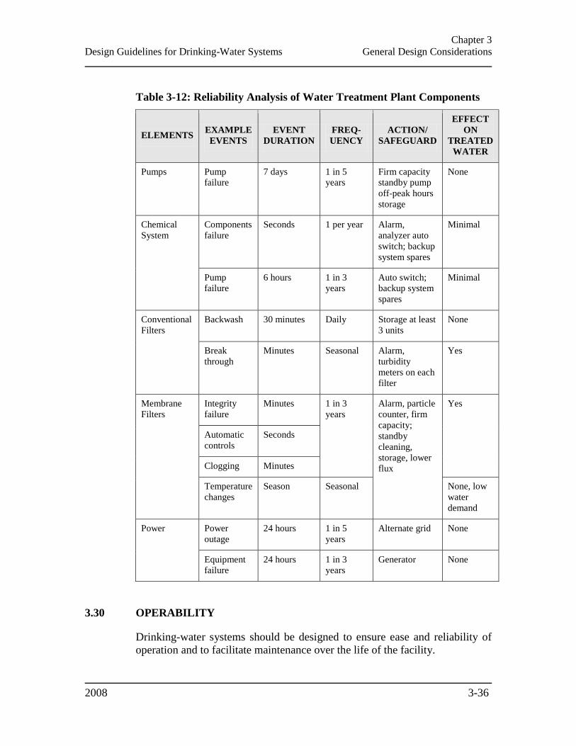
Chapter 3
Design Guidelines for Drinking-Water Systems General Design Considerations
2008 3-36
Table 3-12: Reliability Analysis of Water Treatment Plant Components
ELEMENTS EXAMPLE
EVENTS
EVENT
DURATION
FREQ-
UENCY
ACTION/
SAFEGUARD
EFFECT
ON
TREATED
WATER
Pumps Pump
failure
7 days 1 in 5
years
Firm capacity
standby pump
off-peak hours
storage
None
Chemical
System
Components
failure
Seconds 1 per year Alarm,
analyzer auto
switch; backup
system spares
Minimal
Pump
failure
6 hours 1 in 3
years
Auto switch;
backup system
spares
Minimal
Conventional
Filters
Backwash 30 minutes Daily Storage at least
3 units
None
Break
through
Minutes Seasonal Alarm,
turbidity
meters on each
filter
Yes
Membrane
Filters
Integrity
failure
Minutes 1 in 3
years
Alarm, particle
counter, firm
capacity;
standby
cleaning,
storage, lower
flux
Yes
Automatic
controls
Seconds
Clogging Minutes
Temperature
changes
Season Seasonal None, low
water
demand
Power Power
outage
24 hours 1 in 5
years
Alternate grid None
Equipment
failure
24 hours 1 in 3
years
Generator None
3.30 OPERABILITY
Drinking-water systems should be designed to ensure ease and reliability of
operation and to facilitate maintenance over the life of the facility.

Chapter 3
Design Guidelines for Drinking-Water Systems General Design Considerations
2008 3-37
3.31 CONSTRUCTABILITY
The design of the drinking-water system should allow for the following
factors:
Practicality/ease of construction;
A phased approach;
Maintaining operations during construction; and
Planning for future additions/expansion.
3.32 CLIMATIC FACTORS
The designer should consider potential variations in water levels, water
temperatures, depth of frost, number of frost free days, depth and duration of
snow cover, frequency and size of storm events, as well as other climatic
factors associated with climate change.

Chapter 4
Design Guidelines for Drinking-Water Systems Source Development
2008
CHAPTER 4
SOURCE DEVELOPMENT
4.1 GENERAL .................................................................................................................................... 4-1 4.1.1 Source Water Protection...................................................................................................... 4-1
4.2 SURFACE WATER ...................................................................................................................... 4-2 4.2.1 Quality ................................................................................................................................. 4-2 4.2.2 Minimum Treatment ............................................................................................................ 4-2 4.2.3 Intake Location .................................................................................................................... 4-3 4.2.4 Intake Structures .................................................................................................................. 4-4 4.2.5 Mussel Control .................................................................................................................... 4-5 4.2.6 Impoundments & Reservoirs ................................................................................................ 4-6
4.3 GROUNDWATER ....................................................................................................................... 4-7 4.3.1 General ................................................................................................................................ 4-7 4.3.2 Hydrogeological Studies (GUDI or Groundwater Sources) ................................................ 4-7 4.3.3 Minimum Treatment ............................................................................................................ 4-8 4.3.4 Wellhead Protection ............................................................................................................ 4-8
4.4 GROUNDWATER UNDER THE DIRECT INFLUENCE OF SURFACE WATER ................... 4-8 4.4.1 Minimum Treatment ............................................................................................................ 4-8
4.4.1.1 Bank Filtration (Shore Wells) ........................................................................................................ 4-9 4.4.2 GUDI with In-Situ Filtration ............................................................................................... 4-9
4.5 WELLS ....................................................................................................................................... 4-10 4.5.1 Wells Design ...................................................................................................................... 4-10 4.5.2 Well Pumphouse Design .................................................................................................... 4-10 4.5.3 Decommissioning Wells ..................................................................................................... 4-12

Chapter 4
Design Guidelines for Drinking-Water Systems Source Development
2008 4-1
CHAPTER 4
SOURCE DEVELOPMENT
This chapter addresses the selection and development of surface and groundwater
sources, including water quality and minimum treatment requirements. It also provides
guidance on the design of intake structures and wells.
4.1 GENERAL
In selecting the source of water for a drinking-water system, the designing
engineer should ensure that an adequate quantity of water will be available,
and that the treated water to be delivered to the consumers is in accordance
with the requirements of the Ontario Drinking-Water Quality Standards
regulation (O. Reg. 169/03) and the Drinking-Water Systems regulation (O.
Reg. 170/03), under the Safe Drinking Water Act, 2002, as well as the
Procedure for Disinfection of Drinking Water in Ontario (Disinfection
Procedure) adopted by O. Reg. 170/03 through reference. The treated water
should also be aesthetically acceptable and pleasant to drink.
The control of certain unregulated water quality parameters such as taste,
odour and colour, should result in drinking water which is clear, colourless
and free of objectionable or unpleasant taste or odour. Other aspects of water
quality such as corrosiveness, a tendency to form incrustations and excessive
soap consumption should be controlled on the basis of economic
considerations because of their effects on the distribution system and/or the
intended domestic and industrial use of the water. For the assessment of
aesthetic water quality objectives and treatment needs, the designer is referred
to the ministry document Technical Support Document for Ontario Drinking
Water Standards, Objectives and Guidelines (Technical Support Document).
Each water supply should take its raw water from the best available source
which is technically possible and economically reasonable to treat to the
above standards and objectives.
4.1.1 Source Water Protection
A source water protection plan enacted for protection of groundwater or
surface water from potential contamination should be provided as determined
by the Clean Water Act, 2006 (CWA).

Chapter 4
Design Guidelines for Drinking-Water Systems Source Development
2008 4-2
4.2 SURFACE WATER
Surface water, in this document, refers to water bodies (lakes, wetlands and
ponds, including dug-outs), water courses (rivers, streams, water-filled
drainage ditches), infiltration trenches and areas of seasonal wetlands. Many
of these locations described as surface water would be unsuitable as a source
water supply but are included in the description for full consideration by the
designer as these surface water sources may impact the quality of ground
water (e.g., GUDI).
4.2.1 Quality
A survey and study should be made of the factors, both natural and human,
which may affect water quality. Such survey and study should include, but not
be limited to the following elements:
Determining the degree of control of the watershed area by the
municipality/owner;
Assessing the degree of hazard to the water supply source by agricultural,
industrial, recreational and residential activities in the watershed, and by
accidental spillage of materials that may be toxic, harmful or detrimental
to the treated water quality;
Identifying and assessing all waste discharges (point source and non-point
source) and activities that could impact the water supply source. The
location of each waste discharge should be shown on a general plan;
Obtaining samples over a sufficient period of time to assess variability in
the microbiological, physical, chemical and, when applicable, UV
transmissivity and radiological characteristics of the water; and
Consideration of currents, wind and ice conditions, and the impact of other
contributing water sources.
4.2.2 Minimum Treatment
As required by O. Reg. 170/03, drinking-water systems that obtain water from
a source which is surface water must have a treatment process that is capable
of producing water of equal or better quality than a combination of well
operated, chemically assisted filtration and disinfection processes would
provide. This treatment process must achieve an overall performance that
provides, in accordance with the Disinfection Procedure, a minimum of 2-log
(99%) removal and/or inactivation of Cryptosporidium oocysts, 3-log (99.9%)
removal and/or inactivation of Giardia cysts and 4-log (99.99%) removal
Chapter 4
Design Guidelines for Drinking-Water Systems Source Development
2008 4-3
and/or inactivation of viruses before the water is delivered to the first
consumer.
Higher log removal or inactivation may be needed for a raw water supply
where there is a presence of sewage effluent or other sources of microbial
contamination, such as runoff from livestock operation, and manure storage,
handling or spreading.
The determination of any additional log removal or inactivation required may
also be based upon pathogen monitoring of the raw water. For monitoring
details, the designer is referred to the United States Environmental Protection
Agency (USEPA) guidance manuals Long Term 1 Enhanced Surface Water
Treatment Rule and Long Term 2 Enhanced Surface Water Treatment Rule.
Where necessary, additional treatment should be provided to ensure that the
finished water meets the health based standards described in O. Reg. 169/03,
and to satisfy aesthetic water quality objectives in accordance with the
Technical Support Document.
4.2.3 Intake Location
The design objective in locating the intake should be to provide adequate
quantities and a high and consistent quality of raw water, as confirmed by
samples taken over four seasons at the location and depth of the proposed
intake.
All available water quality information should be examined and the designer
should take particular note of both present and future planned outfalls from
sewage treatment plants and industrial installations, as well as any inshore
pollution, especially during high run-off conditions. Data on current flows and
directions should be reviewed, as well as potentially infrequent occurrences
such as thermoclines or falling plume dispersions, to determine an intake
location that would provide the highest quality water.
Zebra mussels and other molluscs may impact intakes and should be assessed
at the proposed location in the water source.
The final intake location will be affected by bottom contours, subsoils and
available water depths. The submerged depth will also depend on the type of
shipping, if any, which frequents the general location. The designer is referred
to the Navigable Waters Protection Act for guidance. The minimum
submergence from top of intake structure to minimum recorded water level
should be 3m (10 ft) wherever possible.
Chapter 4
Design Guidelines for Drinking-Water Systems Source Development
2008 4-4
4.2.4 Intake Structures
Because of the difficulty and high cost of marine construction, it is suggested
that intake size be sufficient for the projected plant requirement for an
extended design period. This will often result in only a single size difference
in the intake when compared to a 20-year design period. The hydraulic design
for the intake for its final capacity should assume a Hazen-Williams
coefficient, C, of 100.
The intake design and its anchoring should take into account peak wave height
and frequency, and provide adequate protection against ice scouring and
dragging anchors.
The designer should obtain historical information on water depths at the
proposed location and determine whether or not the source level is controlled
and also whether historical minima occurred before or after control measures
were implemented.
The designer should consider the potential occurrence of frazil ice on intakes
when determining crib design and inlet velocities. Intake crib materials should
be of low thermal conductivity, with racks of smooth materials. The design
should provide for low entry velocities – below 75 mm/s (3 in/s) – and
uniform acceleration of water from inlet to intake pipe.
Entrance ports to intakes should be located to prevent sediments from being
picked up. Both top entry and side entry designs are acceptable and may be
evaluated on the basis that:
Side entry designs are less likely to be damaged by anchors; and
Top entry designs provide greater clearance above the river or lake
bottom, and the required inlet area can be more readily attained.
All designs should be checked for transient pressure problems, particularly if
the intake pipe is long or has high design velocities.
For small intakes, consideration should be given to providing means for back-
flushing the intake, if practical.
The designer should consider the need for duplicate intakes, particularly
where:
Damage to an intake may occur by objects such as anchors and nets;
A second intake provides redundancy in the event of changes in water
quality caused by thermoclines; and
Chapter 4
Design Guidelines for Drinking-Water Systems Source Development
2008 4-5
Ambient water quality prevents the use of chlorine for mussel control.
Where deemed necessary, provisions should be made in the intake
structure to control the influx of mussels or other aquatic nuisances
(Section 4.2.5 – Mussel Control).
Under certain circumstances, an intake may not be necessary and a forebay
may be constructed. The designer should ensure that sufficient depth of water
will exist in the forebay under any source conditions, and that the bay can
remain relatively clear of ice.
The design of river intakes differs substantially from that for lakes in that a
substantial current may exist and both anchoring and bottom scouring
considerations will assume greater significance. Where possible, river intakes
should ideally be located well upstream of known point sources of pollution.
The design of intake structures should also provide for:
Withdrawal of water from more than one level if quality varies with depth
and during seasonal events;
Inspection manholes for pipe sizes large enough to permit visual
inspection and/or diver entry for larger intakes; and
Occasional cleaning of the inlet line.
A diversion device capable of keeping large quantities of fish or debris from
entering the intake structure should be provided.
When buried surface water collectors are used, sufficient intake opening area
should be provided to minimize inlet headloss. Particular attention should be
given to the selection of backfill material in relation to the collector pipe slot
size and gradation of the native material over the collector system.
Refer to Section 7.4.1 – Raw Water Pumping and Section 7.5.1 – Raw Water
Pumping (for systems serving fewer than 500 people) for more information
regarding the design of raw water pumping stations. Where the intake or well
is remote from the treatment plant, refer to Section 9.6 –
Automated/Unattended Operation for information regarding the design of
instrumentation and control systems for remote operation.
4.2.5 Mussel Control
Mussels have the potential to obstruct public water supply intakes and cause
loss of intake capacity, as well as contribute to taste and odour problems.
Water suppliers should periodically assess the condition of their intakes to
Chapter 4
Design Guidelines for Drinking-Water Systems Source Development
2008 4-6
determine if mussels are or potentially may be present and implement a
system of control.
The most accepted and currently recommended forms of chemical treatment
for public water supplies are the use of oxidants such as chlorine, chlorine
dioxide, potassium permanganate and ozone. Chemical dosages are typically
applied at the intake through solution piping and a diffuser to prevent the
formation of mussel colonies within the intake and piping. The type of
chemical selected and frequency of application will depend on the type of
existing chemical treatment facilities, mussel breeding season, potential for
trihalomethane (THM) formation, other pre-treatment objectives such as taste
and odour control, safety and economy.
In addition to the chemical methods described above, intake screens
manufactured with special alloys that prevent the growth of zebra mussels on
the intake itself are also available.
The following items should be addressed in the design of a mussel control
system:
Solution piping and diffusers should be positively anchored. Piping should
have appropriate valving and should be installed within the intake pipe or
in a suitable carrier pipe;
A spare solution line should be provided for redundancy;
Chemical feeders should be interlocked with plant system controls to shut
down automatically when raw water flows stop;
Provisions should be included for obtaining raw water samples not
influenced by chemical treatment;
Means to provide adequate flushing; and
The designer may wish to consider the provision of a suitable alternate
intake, as periodic alternating use/zero flow conditions has been
demonstrated to control mussel infestation, where economical.
4.2.6 Impoundments & Reservoirs
Although uncommon in the Province of Ontario, the implementation of source
water protection legislation may create a need for impoundments or reservoirs
for a number of drinking-water systems.

Chapter 4
Design Guidelines for Drinking-Water Systems Source Development
2008 4-7
The designer should be aware that changes in water quality may occur in
impoundments and/or reservoirs, and the intake(s) should be designed
accordingly.
Impoundments and reservoirs should be adequately secured through the use of
fencing, signage and/or patrolling, if necessary.
4.3 GROUNDWATER
4.3.1 General
While other sections of these guidelines apply equally to surface water
sources and groundwater sources, there are a number of special considerations
which relate to groundwater systems that should be reviewed by the designer.
For the purpose of defining minimum treatment of groundwater, a raw water
supply which is groundwater means water located in subsurface aquifer(s)
where the geological materials (sediments) act as an effective filter that
removes micro-organisms and other particles by straining and natural
attenuation of potential pathogens, to a level where the water supply may
already be potable but disinfection is required as an additional health risk
barrier.
Groundwater under direct influence of surface water (GUDI) means
groundwater having incomplete or undependable subsurface filtration of
surface water and infiltrating precipitation. The designer should refer to O.
Reg. 170/03 under which some groundwater supplies are deemed to be
groundwater under the direct influence of surface water systems, unless a
report prepared by a professional hydrogeologist proves otherwise.
4.3.2 Hydrogeological Studies (GUDI or Groundwater Sources)
Prior to the design of a supply structure, adequate geological, hydrological
and water quality studies on the aquifer should be carried out to assess the
suitability of the source and confirm that the proposed groundwater supply is
not a groundwater under the direct influence of surface water. The report
should be prepared by or under the direction of a qualified hydrogeologist.
In particular, the studies should address such factors as establishing the wells'
perennial yields, maximum short-term yields (i.e., over 1 day, 7 days or 90
days) and recommended pump sizing based on a hydrogeologist‟s rating of
the long term yields of the wells. This report should also deal with possible
interference with other existing wells in the area and the potential for
contamination by surface water. Where there is concern about contamination,
an assessment should be completed based on the ministry document Terms of
Chapter 4
Design Guidelines for Drinking-Water Systems Source Development
2008 4-8
Reference for Hydrogeological Study to Examine Groundwater Sources
Potentially Under Direct Influence of Surface Water (PIBS 4167e).
4.3.3 Minimum Treatment
The minimum treatment for groundwater (that is not GUDI) is disinfection.
This treatment process must achieve an overall performance that provides, in
accordance with the Disinfection Procedure, a minimum of 2-log (99%)
removal and/or inactivation of viruses before the water is delivered to the first
consumer.
Where necessary, additional treatment should be provided to ensure that the
finished water meets the health based standards described in O. Reg. 169/03
and to satisfy aesthetic water quality objectives in accordance with Technical
Support Document for Ontario Drinking Water Standards, Objectives and
Guidelines (Technical Support Document) .
4.3.4 Wellhead Protection
The designer should prepare a wellhead protection plan for continued
protection of the water supply from potential sources of contamination, such
as mechanical protection or run-off diversion, in accordance with the
requirements of the ministry document Protocol for Delineation of Wellhead
Protection Areas for Municipal Groundwater Supply Wells under Direct
Influence of Surface Water (PIBS 4168e).
4.4 GROUNDWATER UNDER THE DIRECT INFLUENCE OF SURFACE
WATER
4.4.1 Minimum Treatment
In accordance with O. Reg. 170/03, drinking-water systems that obtain water
from a raw water supply which is GUDI should have a treatment process that
is capable of producing water of equal or better quality than a combination of
well operated, chemically assisted filtration and disinfection processes would
provide. This treatment process must achieve an overall performance that
provides, in accordance with the Disinfection Procedure, a minimum of 2-log
(99%) removal and/or inactivation of Cryptosporidium oocysts, 3-log (99.9%)
removal and/or inactivation of Giardia cysts and 4-log (99.99%) removal
and/or inactivation of viruses before the water is delivered to the first
consumer.
Where necessary, additional treatment should be provided to ensure that the
finished water meets the health based standards described in O. Reg. 169/03,
and to satisfy aesthetic water quality objectives in accordance with the
Technical Support Document.
Chapter 4
Design Guidelines for Drinking-Water Systems Source Development
2008 4-9
4.4.1.1 Bank Filtration (Shore Wells)
Bank filtration is best suited to systems that are located adjacent to rivers with
reasonably good surface water quality and that plan to use bank filtration as
one component of their treatment process. For certain systems, bank filtration
can be an efficient, cost-effective pre-treatment option to improve water
quality or control the extent of sudden changes in raw water temperature and
quality after a storm event; however, only certain sub-surface conditions
provide improved quality.
The designer should consider the type of bed and aquifer material present, the
dynamics of groundwater flow, and the potential for scouring of riverbed
materials at any potential bank filtration site. The degree to which any
particular contaminant will be removed via bank filtration depends on site-
specific conditions and may vary over time. A similar raw water
characterization as for surface water may apply.
4.4.2 GUDI with In-Situ Filtration
When a hydrologeologist report prepared in accordance with the ministry
document Terms of Reference for Hydrogeological Study to Examine
Groundwater Sources Potentially Under Direct Influence of Surface Water
(PIBS 4167e) concludes, and the Director agrees, that adequate in-situ
filtration is provided by the geological materials (sediments), and adequate
wellhead protection measures are being provided, the required minimum
treatment may be achieved, without chemically-assisted filtration, through
disinfection alone.
The disinfection process or combination of disinfection processes should be
capable of providing the required inactivation of oocysts, cysts, and viruses.
To achieve the overall performance specified above, the designer may use a
combination of both ultraviolet disinfection and chemical disinfection.
The development and implementation of microbial contamination control
plans, subject to approval by the ministry, is required for residential drinking-
water systems using GUDI with effective in situ filtration where the
municipality chooses not to provide chemically assisted filtration, or
equivalent treatment, ahead of disinfection. The designer is referred to the
ministry document Development of Microbial Contamination Control Plans
for Municipal Groundwater Supply Wells under Direct Influence of Surface
Water with Effective in situ Filtration4 (PIBS 4008e) for more detailed
information.
4 Development of Microbial Contamination Control Plans for Municipal Groundwater Supply Wells under Direct
Influence of Surface Water with Effective in situ Filtration(PIBS 4008e) comprises two documents, Reference

Chapter 4
Design Guidelines for Drinking-Water Systems Source Development
2008 4-10
4.5 WELLS
4.5.1 Wells Design
The design objectives for a well should be to provide a hydraulically efficient
and structurally sound well that will produce the required water quantity on a
continuous basis, and which is protected from external contamination.
For specific details of yield and drawdown tests in addition to design and
construction criteria, the designer should refer to the Wells Regulation (R.R.O.
1990, Regulation. 903 as amended) under Ontario Water Resources Act and
AWWA Standard A100: Water Wells.
The scope of the hydrogeological study undertaken to determine the aquifer
and well yields should take into account the requirements of the Permit to
Take Water (PTTW) program under Section 34 of the OWRA.
4.5.2 Well Pumphouse Design
In general, the design criteria for well pumping stations follow those presented
for raw and treated water pumping stations. In addition, the following special
considerations apply to wells. The use of well pits to house pumping
equipment is discouraged because of the maintenance and safety problems
associated with this type of construction.
For lineshaft pumps, a pedestal should be provided around the casing to
support the full weight of the pump and to prevent any weight from being
placed on the working casing or any associated well casing. Submersible
pumps may be supported by the casing.
Where wells are completed in flowing artesian conditions, piezometric control
of the aquifer is required. This may be achieved by installing a suitably sized,
valved discharge-to-waste line to convey water from the inner well casing to
outside the building. Flow to waste is discouraged, where possible.
A watertight seal should be provided between the pump base plate or
submersible discharge head and the pump pedestal or between the well casing
and the pump discharge column to prevent the entrance of contaminants.
An aperture for air venting must be provided to the inner well casing. Where
there are indications of excessive quantities of explosive or toxic gases in the
water, the pumphouse should be vented to the outside.
Document (PIBS 5022e) and Guidance Document (PIBS 5023e), and is available in electronic (PDF) format from the ministry Public Information Centre or Drinking Water Management Division, Safe Drinking Water Branch.
Chapter 4
Design Guidelines for Drinking-Water Systems Source Development
2008 4-11
For wells housed within a pumphouse, the well should be located within 1.2 m
(4 ft) of an exterior wall of the pumphouse and centred under a hatchway in
the roof, at least one metre square, to facilitate access by crane.
The piping layout in the pumphouse should include an in-line free discharge
pipe to the outside of the building to permit future testing of the well. The end
of the pipe should be equipped with a free discharge pipe orifice and
manometer tap, calibrated to the design yield of the well. If high static water
levels exist, the designer should consider the use of a by-pass to waste from
the pump to avoid transient high discharge pressures on start-up.
A combination flow controller, with pressure gauges upstream and
downstream, a suitable check valve and an indicating flow meter should be
installed in advance of the free discharge pipe.
A suitable sampling point should be provided upstream of chemical addition
for monitoring well water quality. Water level monitoring equipment should
be provided by including at least one opening in the well head, typically 25
mm (1 in) diameter, which allows vertical access to the inner casing for
equipment installations.
Wells equipped with line shaft pumps should have the casing firmly
connected to the pump structure or have the casing inserted into a recess
extending at least 10 mm (0.4 in) into the pump base. The pump foundation
and base should be designed to prevent water from coming into contact with
the joint. Oil lubricants, if necessary, should be food grade.
Where a submersible pump is used, the top of the casing should be effectively
sealed against the entrance of water under all conditions of vibration or
movement of conductors or cables. The electrical cable should be firmly
attached to the riser pipe at 6 m (20 ft) intervals or less.
The discharge piping should be designed so that the friction loss will be low,
and have control valves and appurtenances located above the pumphouse floor
when an above-ground discharge is provided. Piping should be protected
against the entrance of contamination. Discharge piping should be equipped
with a check valve in or at the well, a shutoff valve, a pressure gauge, a means
of measuring flow, and a smooth nosed sampling tap located at a point where
positive pressure is maintained.
Where applicable, the discharge piping should be equipped with an air
release-vacuum relief valve located upstream from the check valve. An air gap
of at least 150 mm (6 in) or two pipe diameters, whichever is greater, should
be provided between the exhaust/relief piping and the flood rim.
Chapter 4
Design Guidelines for Drinking-Water Systems Source Development
2008 4-12
Appropriate valving should be provided to permit test pumping and control of
each well.
All exposed piping, valves and appurtenances should be protected against
physical damage and freezing.
Piping should be properly anchored to prevent movement and be protected
against transient pressure.
The discharge piping should be provided with a means of pumping to waste or
discharge to irrigation through an air gap backflow preventer. The provision
of facilities for regular, short duration discharges to waste on pump starts can
have a highly beneficial effect on distribution system maintenance
requirements where iron, manganese or sediment are present.
4.5.3 Decommissioning Wells
Unless used for monitoring, all test holes, wells or partially completed wells
should be properly abandoned or decommissioned in accordance with the
requirements of Wells Regulation (R.R.O. 1990, Regulation 903 as amended)
under the Ontario Water Resources Act.
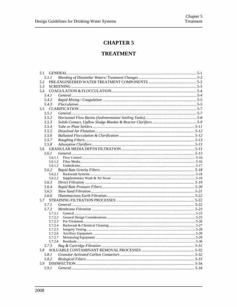
Chapter 5
Design Guidelines for Drinking-Water Systems Treatment
2008
CHAPTER 5
TREATMENT
5.1 GENERAL .................................................................................................................................... 5-1 5.1.1 Blending of Dissimilar Waters/ Treatment Changes ........................................................... 5-2
5.2 PRE-ENGINEERED WATER TREATMENT COMPONENTS ................................................. 5-2 5.3 SCREENING ................................................................................................................................ 5-3 5.4 COAGULATION & FLOCCULATION ....................................................................................... 5-4
5.4.1 General ................................................................................................................................ 5-4 5.4.2 Rapid Mixing / Coagulation ................................................................................................ 5-5 5.4.3 Flocculation ......................................................................................................................... 5-5
5.5 CLARIFICATION ........................................................................................................................ 5-7 5.5.1 General ................................................................................................................................ 5-7 5.5.2 Horizontal Flow Basins (Sedimentation/ Settling Tanks) .................................................... 5-8 5.5.3 Solids Contact, Upflow Sludge Blanket & Reactor Clarifiers ............................................. 5-9 5.5.4 Tube or Plate Settlers ........................................................................................................ 5-11 5.5.5 Dissolved Air Flotation...................................................................................................... 5-12 5.5.6 Ballasted Flocculation & Clarification ............................................................................. 5-12 5.5.7 Roughing Filters ................................................................................................................ 5-13 5.5.8 Adsorption Clarifiers ......................................................................................................... 5-13
5.6 GRANULAR MEDIA DEPTH FILTRATION ........................................................................... 5-13 5.6.1 General .............................................................................................................................. 5-13
5.6.1.1 Flow Control ................................................................................................................................ 5-16 5.6.1.2 Filter Media .................................................................................................................................. 5-16 5.6.1.3 Underdrains .................................................................................................................................. 5-17
5.6.2 Rapid Rate Gravity Filters ................................................................................................. 5-18 5.6.2.1 Backwash Systems ....................................................................................................................... 5-18 5.6.2.2 Supplementary Wash & Air Scour ............................................................................................... 5-19
5.6.3 Direct Filtration ................................................................................................................ 5-19 5.6.4 Rapid Rate Pressure Filters ............................................................................................... 5-20 5.6.5 Slow Sand Filtration .......................................................................................................... 5-21 5.6.6 Diatomaceous Earth Filtration .......................................................................................... 5-22
5.7 STRAINING FILTRATION PROCESSES ................................................................................ 5-22 5.7.1 General .............................................................................................................................. 5-22 5.7.2 Membrane Filtration ......................................................................................................... 5-23
5.7.2.1 General ......................................................................................................................................... 5-23 5.7.2.2 General Design Considerations .................................................................................................... 5-23 5.7.2.3 Pre-Treatment ............................................................................................................................... 5-26 5.7.2.4 Backwash & Chemical Cleaning .................................................................................................. 5-27 5.7.2.5 Integrity Testing ........................................................................................................................... 5-28 5.7.2.6 Ancillary Equipment .................................................................................................................... 5-28 5.7.2.7 Monitoring Equipment ................................................................................................................. 5-29 5.7.2.8 Residuals ...................................................................................................................................... 5-30
5.7.3 Bag & Cartridge Filtration ............................................................................................... 5-31 5.8 SOLUABLE CONTAMINANT REMOVAL PROCESSES ...................................................... 5-32
5.8.1 Granular Activated Carbon Contactors ............................................................................ 5-32 5.8.2 Biological Filters ............................................................................................................... 5-33
5.9 DISINFECTION ......................................................................................................................... 5-34 5.9.1 General .............................................................................................................................. 5-34

Chapter 5
Design Guidelines for Drinking-Water Systems Treatment
2008
5.9.2 Disinfection By-Products ................................................................................................... 5-34 5.9.3 Inactivation ........................................................................................................................ 5-35 5.9.4 Chemical Inactivation Agents ............................................................................................ 5-35
5.9.4.1 Free Chlorine ................................................................................................................................ 5-35 5.9.4.2 Combined Chlorine ...................................................................................................................... 5-35 5.9.4.3 Ozone ........................................................................................................................................... 5-36 5.9.4.4 Chlorine Dioxide .......................................................................................................................... 5-36
5.9.5 Ultraviolet Light Inactivation ............................................................................................ 5-37 5.9.5.1 General ......................................................................................................................................... 5-37 5.9.5.2 UV Dosages ................................................................................................................................. 5-38 5.9.5.3 Water Quality ............................................................................................................................... 5-38 5.9.5.4 Hydraulics .................................................................................................................................... 5-39 5.9.5.5 Operational Control Strategies ..................................................................................................... 5-40 5.9.5.6 Performance Validation ................................................................................................................ 5-40 5.9.5.7 Alarms .......................................................................................................................................... 5-41 5.9.5.8 Other Considerations .................................................................................................................... 5-42
5.10 AERATION & AIR STRIPPING ........................................................................................... 5-43 5.10.1 General ......................................................................................................................... 5-43
5.11 SOFTENING .......................................................................................................................... 5-44 5.11.1 General ......................................................................................................................... 5-44 5.11.2 Lime or Lime-Soda Process .......................................................................................... 5-44 5.11.3 Ion Exchange Process ................................................................................................... 5-45
5.12 IRON & MANGANESE CONTROL ..................................................................................... 5-47 5.12.1 General ......................................................................................................................... 5-47 5.12.2 Air/Chlorine Oxidation of Iron ..................................................................................... 5-48 5.12.3 Sequestering with Silicates or Polyphosphates ............................................................. 5-48 5.12.4 Ion Exchange in Regular Softeners ............................................................................... 5-50 5.12.5 Greensand Type Processes ........................................................................................... 5-50 5.12.6 Preoxidation & Chemically Assisted/Membrane Filtration .......................................... 5-52
5.13 NATURAL ORGANIC MATTER CONTROL ..................................................................... 5-53 5.13.1 General ......................................................................................................................... 5-53 5.13.2 Activated Carbon .......................................................................................................... 5-53 5.13.3 Nanofiltration................................................................................................................ 5-54
5.14 TASTE & ODOUR CONTROL ............................................................................................. 5-54 5.14.1 General ......................................................................................................................... 5-54 5.14.2 Microscreening ............................................................................................................. 5-54 5.14.3 Oxidation ...................................................................................................................... 5-55 5.14.4 Advanced Oxidation ...................................................................................................... 5-55 5.14.5 Activated Carbon .......................................................................................................... 5-56
5.14.5.1 Powdered Activated Carbon ................................................................................................... 5-56 5.14.5.2 Granular Activated Carbon ..................................................................................................... 5-56
5.15 NITRITE/ NITRATE REMOVAL ......................................................................................... 5-57 5.16 ARSENIC REMOVAL .......................................................................................................... 5-57 5.17 FLUORIDE REMOVAL ........................................................................................................ 5-58 5.18 INTERNAL CORROSION CONTROL ................................................................................. 5-58
5.18.1 General ......................................................................................................................... 5-58 5.18.2 Raising pH, Alkalinity & Carbonate Buffer Level ........................................................ 5-60 5.18.3 Commercial Corrosion Inhibitors ................................................................................. 5-60 5.18.4 Carbon Dioxide Reduction by Aeration ........................................................................ 5-61 5.18.5 Limestone Chip Contactors ........................................................................................... 5-61
Chapter 5
Design Guidelines for Drinking-Water Systems Treatment
2008 5-1
CHAPTER 5
TREATMENT
This chapter describes design considerations for various water treatment processes. The
design of treatment processes and devices should depend on evaluation of the nature and
quality of the particular water to be treated, seasonal variations, the desired quality of the
finished water and the mode of operation planned.
5.1 GENERAL
For the design of a new plant, the designer should use pilot plant data that has
been accumulated over a period of time that at a minimum would cover winter
and summer operations, and over a wide range of historically demonstrated
raw water conditions (at a minimum winter and summer). Where no such data
are available, treatability studies should be conducted covering the full range
of water quality conditions. Care should be exercised in interpreting
treatability study data since they may not provide information directly
appropriate for scale-up of attributes such as reaction and retention times and
filtration rates. Samples should be taken at the proposed intake location and
depth to establish a data base for design. The design of the process units
should become progressively more conservative as the quantity and reliability
of experimental or operating data decreases. Consideration of variable surface
water quality due to seasonal changes can be crucial in the selection of
processes and equipment.
In some cases, design parameters may be determined by other means such as
experience with similar water in other locations or literature searches, if
properly documented.
When designing an expansion of an existing water treatment plant, the
designer should determine the treatment needs for the specific raw water
source, as described in Section 4.1 – General, based on operating data
accumulated over a substantial period of time (i.e., at least three years). Where
a particular water quality parameter is the principal factor in treatment design,
sufficient data should be gathered for proper statistical analysis.
The designer should consider water quality and regulatory requirements
together with the following site specific treatment considerations:
Pathogen removal/inactivation;
Control of disinfection by-products (DBP);
Chapter 5
Design Guidelines for Drinking-Water Systems Treatment
2008 5-2
Control of health-related parameters;
Control of aesthetic parameters;
Flexibility to respond to „emerging‟ or newly identified and detectably
present contaminants;
Potential for accelerated corrosion or scale formation; and
Readily available biological nutrient levels in the treated water.
Other considerations include operability, reliability, flexibility for expansion,
site limitations, social considerations (impact on neighbours and surrounding
area), minimizing the impact to the natural environment and economics (both
capital and operation/maintenance costs).
5.1.1 Blending of Dissimilar Waters/ Treatment Changes
If a new water supply source is brought into service with the existing supply,
it is possible to create water quality problems when the dissimilar waters are
blended within the distribution system. Likewise, changes to treatment and/or
disinfection that alter the chemical characteristics of the treated water may
also have an adverse impact on the distribution system and household
plumbing. For example, if surface water with higher dissolved oxygen levels
is blended with ground water, iron or manganese can be precipitated. Another
potential impact is increased corrosivity in the zone served by the new/
changed source of water supply. The designer should consider the potential
water quality impacts of adding a new source or changing the existing one and
provide additional/ modified treatment if necessary.
5.2 PRE-ENGINEERED WATER TREATMENT COMPONENTS
Pre-engineered water treatment components are normally modular process
units which are pre-designed for specific process applications and flows.
Multiple units may be installed in parallel to accommodate larger flows.
Pre-engineered treatment components are especially applicable for small
systems where individually engineered treatment plants may not be cost
effective. Factors to be considered when selecting a pre-engineered water
treatment component include:
Demonstration of treatment train/unit process effectiveness under all raw
water conditions and system flow demands, especially for winter
conditions and northern waters;
Chapter 5
Design Guidelines for Drinking-Water Systems Treatment
2008 5-3
Means to optimize treatment and the flexibility to handle the process
residuals generated;
Sophistication of equipment and the reliability and experience record of
the proposed treatment equipment and controls;
Operational oversight that is necessary (i.e., full time operators or
automation plan);
Formal commissioning, start-up and follow-up training, operations and
maintenance manuals and troubleshooting available from the manufacturer
or contractor;
Manufacturer warranty, replacement guarantee and confirmation of
meeting performance objectives;
Timely availability of parts and service; and
Estimated annual operating and maintenance costs.
Pre-engineered treatment components require significant engineering and
integration with other components, such as chemical feed and storage systems,
building, electrical and plumbing systems, as well as instrumentation and
controls.
5.3 SCREENING
Raw water screens should be provided for removal of large solids, with the
screen mesh size and materials of construction consistent with the raw water
quality. A screen mesh size of 10 mm (0.4 in) is common (a smaller size is
typically required for membrane applications). The screen should be sized for
a maximum velocity of water through the screen of 0.6 m/s (2 ft/s) regardless
of water level in the screen well. Where parallel screens are used, the
maximum velocity with one screen out of service should not exceed 0.9 m/s (3
ft/s).
A minimum of two screens should be provided. Depending on the size of the
plant, the design may consider provision of either two fixed screens in series,
two rotating mechanical screens in parallel, or one rotating screen plus one
fixed screen in series. In each case, the designer should ensure that sufficient
space exists above the screen to permit removal.
Fixed screens should have suitable lifting lugs on the screen, and a lifting
hook or beam positioned above the screen to assist in removing it. When it is
intended that screens be cleaned manually, the designer should pay particular

Chapter 5
Design Guidelines for Drinking-Water Systems Treatment
2008 5-4
attention to the size of screen sections and materials of construction to ensure
that screen removal and handling can be readily accomplished.
Rotating screens should have either automatic or manual advance mechanisms
arranged so that complete washing of the screen is accomplished. Head-loss
metering equipment should be installed to monitor and react to excessive head
loss, and for automatic systems, trigger cleaning. The screen rotation should
be such that even wear is obtained from all sections.
For either type of screen, washing facilities should be provided using high
pressure water through an appropriately sized line. Screen washings should be
diverted to a holding tank, preferably with a basket type screen, so that screen
wastes can be simply dewatered prior to adequate disposal. Screen wastes
should not be returned to the raw water well.
Where micro-screens are provided for removal of algae, larger pore size pre-
screens should be provided to protect the mesh of the micro-screens.
Screen wells should be of watertight design with provision made either
through valving or stop logs for isolation of the well for cleaning or
inspection. Where there are multiple screen wells, means for isolation of these
wells for maintenance purposes should be provided to ensure continued
operation of the plant. The screen well should be covered with a curb around
any floor openings to prevent water running from the floor into the well.
Wells should be provided with differential level indicating devices to permit
the headloss across the screen to be determined to assess the need for
cleaning.
The designer should be aware of the potential of frazil ice formation and
plugging of screens with a shallow depth of intake. Protection from this may
best be achieved by installation of a boom enclosing the area over the intake
to accelerate ice cover formation. The provision for back flow and/or local
heating may also be considered. Refer to Section 4.2 – Surface Water for
information regarding the design of intake facilities.
5.4 COAGULATION & FLOCCULATION
5.4.1 General
The effective removal of colloidal/micron-sized particles using granular media
depth filters requires chemical destabilization of suspended particles so they
will agglomerate into settling floc or adhere to the media. Design
considerations for coagulation and flocculation processes include: the type,
concentration and dosage range of coagulants, coagulant aids or flocculant
Chapter 5
Design Guidelines for Drinking-Water Systems Treatment
2008 5-5
aids; rapid mixing of the chemicals into the water; flocculation methods,
intensities and time; and downstream processes.
5.4.2 Rapid Mixing / Coagulation
The design objective of the rapid mix/coagulation step is to provide high
intensity mixing to thoroughly distribute the coagulant chemical in advance of
the hydrolysis reaction that takes only seconds to complete. Coagulation may
be achieved either in a separate process tank or by the use of an in-line mixer.
The detention period in the mixing zone should be minimized and limited to
no more than thirty seconds.
Static mixing devices can be used to provide effective mixing only where the
flow is constant and close to the design maximum of the mixer. When
selecting a static mixer, the designer should take into consideration that minor
reductions in flow rate through these mixers can result in significant
reductions in the mixing power delivered. This may reduce the flexibility to
operate treatment effectively at reduced throughput. Power mixers are
preferred where flow is expected to vary. The designer should ensure easy
access for maintenance and replacement of the rotating seal of power mixers.
Chemical diffusers are a component of all rapid mixing systems. The designer
should be aware that solids-forming reactions that may plug the diffuser can
occur and should make appropriate provisions for removal and cleaning.
Typically, a rapid mixer with a mixing intensity velocity gradient (G value) in
the order of 1000 s-1
is effective. Adding coagulants to raw water wells and
allowing pumping units to perform the mixing process is not recommended.
Where alkalinity or pH adjusting chemicals, powdered activated carbon
(PAC) or potassium permanganate use is anticipated, addition of these should
take place 3 to 5 minutes upstream of coagulant addition.
5.4.3 Flocculation
Following coagulation, flocculation is used to enhance the collisions of
destabilized colloidal particles and their enmeshment into settleable and
filterable floc sizes. Polymer flocculation aids and activated silica should not
be subjected to high shear mixing. Provisions should be made for separate
addition downstream of coagulant mixing. A delay period of 3 to 5 minutes is
recommended. The mixing should be thorough enough to provide
opportunities for the particles to collide but also gentle enough to prevent the
flocculated particles from breaking apart.
Required detention time for adequate flocculation is variable depending on
water temperature and the type of downstream processes. When sedimentation
is included, detention times of 25 to 30 minutes are usually sufficient in
Chapter 5
Design Guidelines for Drinking-Water Systems Treatment
2008 5-6
summer. When water temperatures are <5°C (<41°F), floc formation is slower
and longer detention times of 30 to 40 minutes or longer may be needed. For
direct filtration, the detention time required is usually less, typically 15
minutes. Even shorter times may be adequate for coagulation/flocculation for
membrane filtration. However, if the flocculation time prior to membrane
filtration is too short, or control of pH, alkalinity and buffering capacity of the
water is inadequate when using aluminum based coagulants, dissolved
aluminum concentrations in the permeate may exceed the Ontario operational
guideline and/or may prematurely foul the membrane.
Typically, G values of 10 to 70 s-1
are needed for successful flocculation.
Tapered flocculation (reducing G in each stage) is desirable, typically
designed as three or four sequential process tanks. Lower velocity gradients
are required for the more fragile colour floc than for flocculated suspended
material (turbidity). Higher velocity gradients are needed for direct filtration
to produce denser pin-point floc.
Optimum G and Gt (incorporating the time that the mixing intensity is
applied) values are best determined by pilot studies. Jar testing does not
always involve back-mixing which is typical for flocculation processes and is
therefore a limited guide for full scale design.
To permit flexibility of operation and for maintenance purposes, two separate
flocculation tanks should be provided as a minimum. To prevent short-
circuiting, each tank should be divided into at least two stages. The design of
the basin inlet and outlet should consider short-circuiting and shearing of floc.
A drain and/or pumps should be provided to handle dewatering and cleaning.
A superstructure (i.e. cover or enclosure) over the flocculation basins is
needed.
Mixing may be provided either mechanically or hydraulically, provided that
sufficient flexibility of operation is possible, and that G values can be varied
to allow for optimization of the process. Where mechanical agitation is
provided, submerged bearings are not recommended, and all submerged parts
should have sufficient corrosion resistance to withstand long term use with
coagulated water.
Flocculation and sedimentation basins should be as close together as possible.
The velocity of flocculated water through pipes or conduits to settling basins
should not be less than 0.15 m/s (0.5 ft/s) or greater than 0.6 m/s (2 ft/s).
Flocculated water should never be pumped between the flocculation and
sedimentation units as this will break floc. The designer of pipes and conduits
should minimize changes of direction in order to avoid turbulence.

Chapter 5
Design Guidelines for Drinking-Water Systems Treatment
2008 5-7
5.5 CLARIFICATION
5.5.1 General
The design objective of the clarification process is to reduce the settleable
solids loading on subsequent filtration processes. A minimum of two
clarifier/sedimentation tanks is recommended. Where only one sedimentation
tank is provided, sufficient finished water storage should be provided to allow
continuous water supply while the clarifier/settling tank is out of service.
Alternatively, provision should be made to produce water without clarification
during tank cleaning periods. It is recommended that a by-pass pipe or conduit
be provided.
Clarification processes can be categorized into general types: horizontal flow
sedimentation basins, upflow reactor and sludge blanket clarifiers, adsorption
clarifiers, dissolved air floatation and ballasted sand or high-rate microsand
process. High rate settlers are modified sedimentation tanks or clarifiers with
plate or tube modules placed into the basin to increase the settling area and
reduce the distance flocs have to fall.
The primary design parameter is the surface overflow rate. The type of
clarification process, the performance required in terms of clarified water
suspended solids, generally measured as turbidity, the type of flocculated
material generated prior to clarification and the temperature of the water all
dictate the optimum overflow rate.
A superstructure ( i.e. cover or enclosure) over the tanks is needed. If there is
no mechanical equipment in the tanks and provisions are included for
adequate monitoring under all expected weather conditions, a cover may be
adequate. Roof drainage should be provided and should not discharge into the
tank. The designer should allow for the possibility of ice formation within
settling tanks which could fall and cause damage to submerged tubes or other
components within the tank if the water level is dropped. Corrosion-resistant
materials should be used for tanks, piping and appurtenances.
Inlets and outlets should be designed to ensure that water is distributed evenly
across the clarifier/settling tank at uniform velocities to minimize short-
circuiting. In selecting the sludge collection system, the designer should
consider site-specific weather conditions (potential for ice formation), the
nature and quantity of suspended solids in the raw water, the type of
coagulant(s) used, the shape of the tanks and provision for installation of high-
rate settlers.
Drainage systems should allow the tank to empty within a reasonable time
(e.g., 8 hours).

Chapter 5
Design Guidelines for Drinking-Water Systems Treatment
2008 5-8
Safety of the employees must be considered in the design of tanks. As a
minimum, the design should conform to Ontario Ministry of Labour
requirements, other applicable laws and regulations of the Province and local
municipal building department requirements. Confined space entry
requirements should be considered. Ladders, ladder guards, railings,
handholds and entrance hatches should be provided where applicable. The
design should incorporate easily accessible fall arrest systems for use by
employees or emergency response workers. Openings into tanks should be
curbed and covers should have a locking device. Additional, appropriately
sealable, small openings into the tanks may be appropriate for venting, testing
purposes such as dye tests for short circuit detection, or observation of settling
characteristics.
5.5.2 Horizontal Flow Basins (Sedimentation/ Settling Tanks)
Typically, surface overflow rates (SORs) for sedimentation tanks are from
<1.0 to 2.4 m/h (<0.4 to 1.0 USgpm/ft²). Low rates are normally needed for
colour removal and high rates are suitable for turbidity removal. Where water
temperatures are consistently lower than 10ºC (50ºF), SORs should be toward
the lower end of the range. For plant capacities less than 10,000 m3/d, where
sedimentation efficiencies are frequently lower than in larger plants, SORs
may need to be reduced by 15 to 25% to achieve the desired results on a
regular basis. The designer should also consider the following parameters:
Water depth of 3 to 4.5 m (10 to 15 ft);
Mean flow velocity of 0.3 to 1.1 m/min (1 to 3.6 ft/min);
Length to width ratio – minimum 4:1;
Water depth to length ratio – minimum 1:15; and
Weir loading 9 to 13 m3/(m·h) (12 to 18 USgpm/ft).
Maximum entrance velocities should not exceed 0.6 m/s (2 ft/s). Fixed or
adjustable baffles should be provided as necessary to achieve the maximum
potential for settling. In evaluating different inlet baffling methods or
hydraulic scale model studies, the designer should ensure that the maximum
number of ports is provided, that the ports uniformly distribute flow across the
baffle wall and that the headloss through the ports allows for equalization of
flow distribution across the entire cross section of the tank inlet with
minimum floc breakage. The water exiting the settling tank should be
uniformly collected across an area that is perpendicular to the flow direction
either by a submerged pipe or across a weir.
Chapter 5
Design Guidelines for Drinking-Water Systems Treatment
2008 5-9
The velocity of the flow into the submerged pipe or across a weir will depend
on the individual design. The use of submerged orifices is recommended in
order to provide a volume above the orifices for storage when there are
fluctuations in flow. Submerged orifices should not be located more than 1m
(3 ft) below the water level. Where submerged outlets are used, each tank
should be provided with a suitably sized overflow or other means to prevent
flooding. Any overflow should be located so as to be readily visible.
Sludge collection systems should ensure full tank coverage. Where it is
proposed to remove sludge manually, the tank bottom should be sloped,
typically 1:100, toward the inlet end. Flushing lines or hydrants should be
provided and should be equipped with appropriate backflow prevention
devices. For sludge removal by travelling siphon or scraping mechanisms, the
tank bottom should be flat. Where sludge is to be removed by pumping from
sludge hoppers, the hopper design should be consistent with the flow
characteristics of the sludge produced.
Sludge draw-off methods should take into account that sludge loadings near
the tank inlet may be substantially higher than at other locations. Sludge
withdrawal piping should be designed so that material withdrawn can be
observed to ensure that sludge rather than settled water is being removed.
Sludge pipes should be not less than 75 mm (3 in) in diameter and arranged to
facilitate cleaning. The entrance to sludge withdrawal piping should be
designed to prevent clogging. Valves should be located outside the tank for
accessibility. All valve operators which are not within buildings should be
tamper proof with provision for locking.
5.5.3 Solids Contact, Upflow Sludge Blanket & Reactor Clarifiers
Solids contact, upflow and reactor clarifiers are proprietary settling units that
have their basic sizes and associated equipment pre-established by the
manufacturers based on flow. Solids contact, upflow sludge blanket or reactor
clarifiers are most efficient where water characteristics, especially
temperature, do not fluctuate rapidly, and where flow rates are effectively
constant and operation is continuous. In the evaluation of proprietary settling
units, the designer may consider the following factors.
Clarifiers should be designed for the maximum uniform flow rate and should
be adjustable to react to gradual changes in flow and water characteristics.
Effective back-mixing devices should provide good mixing of the influent
water (raw water plus coagulant) with previously formed sludge particles and
prevent deposition of solids in the mixing zone. Depending on the design of
the clarifier, a separate rapid mixing process to distribute the coagulant
Chapter 5
Design Guidelines for Drinking-Water Systems Treatment
2008 5-10
uniformly throughout the process stream upstream of the clarifier may be
required.
The flocculation and mixing detention time should not be less than 30 minutes
at the expected design maximum flow. If applicable, flocculation equipment
should be adjustable (speed and/or pitch) and the clarifier design should
provide for coagulation in a separate chamber or baffled zone within the unit.
The units should be equipped with either overflow weirs or orifices
constructed so that water at the surface of the unit does not travel more than 3
m (10 ft) horizontally to the collection trough. Weirs should be adjustable, and
the summed total lengths should be at least equivalent to the perimeter of the
tank. Weir or orifice loading rates will depend on the individual design of the
clarifiers. Either should produce uniform rise rates for the entire area of the
tank.
Surface overflow rates range from 1.2 to 6.0 m/h (0.5 to 2.5 USgpm/ft²),
depending on the design of the clarifier and the water being treated. The high
rates are for clarifiers which include plate or tube settlers. Low rates are
normally needed for colour removal and higher rates are suitable for turbidity
removal.
Recirculation impellers should have an adjustable speed ratio of 1 to 4. Rake
speed should be variable from 0.3 to 4.0 m/min (1 to 13 ft/min). Where the
proposed operation is “stop-start” mode, the design should allow sludge
recirculation to continue when raw water flow stops to prevent process upsets
of sludge recirculation type clarifiers. The raw water inlet valve should be of
the slow opening type operating over not less than one minute to prevent
disruption of the floc blanket.
Sludge removal design should include:
Sludge pipes greater than or equal to 75 mm (3 in) in diameter and
arranged to facilitate cleaning;
An entrance to sludge withdrawal piping that prevents clogging;
Valves located outside the tank for accessibility; and
Observation, sludge density monitoring, sampling and control of sludge
being withdrawn from the unit.
Either internal or external concentrators should be provided in order to obtain
a concentrated sludge with a minimum of wastewater. Typically, total water
Chapter 5
Design Guidelines for Drinking-Water Systems Treatment
2008 5-11
losses should not exceed 5%. Solids concentration of sludge bled to waste
should be ≥3% by weight.
Discharge from blow-off outlets and drains should be treated as wastewater.
Cross-connection control should be included for the drinking water lines used
to backflush sludge lines.
Clarifiers should be covered either by locating them within the plant or by the
use of a separate cover with personnel access to permit visual inspection of
the treatment. Where open top clarifiers are proposed, the equipment should
be properly weatherproofed and the rake mechanisms should be equipped with
torque switches to prevent overloading. Ice blockage of effluent launder
orifices may occur unless these orifices are sufficiently covered to remain ice-
free, thus increasing the operating depth of the clarifier.
5.5.4 Tube or Plate Settlers
Tube or plate settlers should be inclined at an angle of 55 to 60 . Settling
tanks with tube or inclined plate settler units should be designed to ensure
uniform flow distribution into an entire unit, to minimize short-circuiting and
to maintain velocities suitable for settling within the unit [an average velocity
of 0.15 to 0.2 m/min (0.5 to 0.7 ft/min) is normally used for settling alum
floc]. An approaching flow velocity of approximately 0.6 m/min (2 ft/min)
should be used in the settling tank upstream of the tube or plate settler unit.
SORs for tanks with tube/inclined plate settlers range from 2.5 to 5.0 m/h (1.0
to 2.0 USgpm/ft²) where the effective settling area is the footprint area (i.e.,
before the plates or tubes are installed).
The designer of high rate settlers units should consider the following: settling
velocity and characteristics of the suspended solids; flow velocity within the
settler unit; surface loading; selection of the appropriate sludge removal
equipment to be installed underneath the settler unit; spacing of launders to be
installed above the settler unit with weir loadings of 3.7 to 7.5 m3/m·h (5 to10
USgpm/ft).
Provisions should be made for cleaning and/or removal of plates or tubes and
sludge removal. Flushing lines should be provided to facilitate maintenance
and should be properly protected against backflow or backsiphonage. Drain
piping from the settler units should be sized to facilitate a quick flush of the
settler units and to prevent flooding.
Chapter 5
Design Guidelines for Drinking-Water Systems Treatment
2008 5-12
5.5.5 Dissolved Air Flotation
Dissolved air flotation (DAF) offers special advantages with high colour, low
turbidity raw water, or water with high algae content which causes floc to
settle very slowly or to float upwards. The retention time and loading rates for
dissolved air flotation units depends largely on the water being treated, the
nature of the contaminant being removed, the chemicals used and the design
of the DAF process. Traditional loading rates have been in the 10 to 12 m/h (4
to 5 USgpm/ft²) range; however, higher loading rates, up to 29 m/h (12
USgpm/ft2) may be used if confirmed through appropriate pilot testing.
The tank length should be no greater than 12 m (39 ft) to control the density of
the bubble blanket. Tank depth should be 1.5 to 3.0 m (5 to 10 ft); greater
depths are recommended for high algae loads. Flow velocities should be
designed to limit scouring of the float from below. An inlet baffle should
create a contact zone volume large enough to provide good floc/bubble
contact time, but not so large as to encourage short circuiting. The angle of the
baffle should be 60 to 90 , depending on the hydraulic loading rate.
The air saturated recycle flow should be adjustable and introduced at a
location which ensures even distribution of the released air at the tank
influent. The recycle ratio should be between 5 and 12% of inlet flow. The air
flow should also be adjustable and the air injection designed to ensure an even
distribution of air across the inlet baffle. Bubble diameter should be between
10 and 100µm. Saturation pressure should be 415 to 725 kPa (60 to 105 psi).
The DAF effluent (subnatant) should be removed from a submerged location
near the basin floor, usually by way of an underflow baffle or perforated pipe
laterals. The float- sludge may be removed hydraulically or mechanically. In
selecting the float-sludge removal system, the residuals handling system
should be considered.
The designer may consider the use of DAF on a seasonal basis (e.g., for algal
blooms).
5.5.6 Ballasted Flocculation & Clarification
This is a proprietary treatment system which operates in up-flow mode and
uses microsand-enhanced flocculation and lamellar settling for clarification.
The process may allow very high loading rates, and therefore a smaller
footprint, in comparison to conventional flocculation and sedimentation.
Typical hydraulic loading rates are 35 to 73 m/h (14 to 30 USgpm/ft²). This
process may need a specific combination of chemicals for effective treatment
depending on a raw water quality. A means to recycle and clean the sand
ballast for reuse in the process should be provided. The designer may consider
this process, particularly for situations where the site area is limited, for the
Chapter 5
Design Guidelines for Drinking-Water Systems Treatment
2008 5-13
clarification process in the main treatment train or where backwash water is to
be clarified before recycling (Section 11.2.3 – Membrane Filtration).
5.5.7 Roughing Filters
Roughing filters are an alternative clarification process which may be
operated in either up-flow or down-flow mode. They create a zone of laminar
flow and suspended particulate deposits on the filter media. To clean the filter,
the media is agitated to loosen the solids, or in the case of upstream roughing
filters, is such that the flow can be controlled to allow water to flow
backwards (down) through the filters. Roughing filters are frequently used
upstream of slow sand filters when the source water requires pre-treatment to
remove coarse particles that could lead to unacceptable rates of headloss
development.
5.5.8 Adsorption Clarifiers
Adsorption clarifiers operate on the principle of granular media flocculation.
The flocculation and clarification process takes place as the coagulated water
travels upwards through a buoyant plastic media. Flocculated solids are
trapped in the media. These systems are proprietary and use a combination of
hydraulic flocculation, roughing filtration and rapid rate filtration. SORs are in
the range of 19.5 to 25.5 m/h (8 to 10 USgpm/ft²). Air scour should be
provided for cleaning the filters. Pilot testing is recommended for site specific
applications.
5.6 GRANULAR MEDIA DEPTH FILTRATION
5.6.1 General
The designer should evaluate the following interrelated factors when
designing a granular media filtration process: the requirements of the filtered
water quality specified in the Procedure for Disinfection of Drinking Water in
Ontario (Disinfection Procedure); site specific conditions including raw water
quality; pre-treatment process(es) and associated chemical application points;
plant size/capacity; materials of construction; type of filtration technology;
filtration rate; control of filtration rate; type of filter bed including the media
size, thickness of media layers, and number of independent filters; available
headloss for filtration; type of media support and underdrain; type of filter
wash system; and filter-to-waste. Treatment and/or disposal of waste residuals
should also be considered in the selection and design of the filtration process.
The number of filters/filter trains provided should depend on the process
selected; i.e., with or without prior clarification, the method of plant operation,
the method of filter control and the quantity of available storage.
Chapter 5
Design Guidelines for Drinking-Water Systems Treatment
2008 5-14
At least two filters should be provided, each capable of independent operation
and backwashing. Where only two units are provided, the filters should be
capable of meeting the plant gross design capacity at the design filtration rate
and, for security of supply, consideration should be given to having additional
filter area so that each filter is capable of meeting the majority of plant gross
design capacity at the design filtration rate.
Where more than two filter units are provided, the filters should be capable of
meeting the plant gross design capacity at the design filtration rate and each
filter should be capable of independent operation and backwashing.
To avoid the potential for turbidity breakthrough, the designer should select an
adequate number of filters and area of each filter bed so the filtration rate can
remain the same or not increase substantially (less than 10% gradual change in
hydraulic loading) during the backwashing of filters.
The filtration rate and terminal head loss for a particular type of filter and
filtration medium design should be selected considering total required area of
the filter bed, the available hydraulic loss during filtration, the anticipated
terminal head loss prior to turbidity breakthrough in the filter bed and the
anticipated filter run.
All filters should be equipped as follows:
Means for obtaining influent and effluent samples;
Indicating flow meter and flow control to each filter/filter train;
Continuous effluent turbidity measuring and recording device; particle
monitoring equipment may be useful in enhancing overall treatment
operations;
Indicating loss of head gauge;
Provisions for filtering-to-waste with appropriate measures for backflow
prevention or operational procedures to achieve the same water quality
results;
Wall sleeves providing access to the filter interior at several locations for
sampling or pressure sensing or equivalent other devices; and
Pressure hose [25 to 37 mm (1 to 1.5 in)] and storage rack at the operating
floor for washing filter walls (gravity filters).
The filter structure should be designed to provide for:
Chapter 5
Design Guidelines for Drinking-Water Systems Treatment
2008 5-15
Vertical walls within the filter;
No protrusion of the filter walls into the filter media;
Cover or enclosure by superstructure;
Head room to permit normal inspection and operation;
Minimum depth of filter box of 2.5 m (8.2 ft);
Minimum water depth over the surface of the filter media of 1 m (3 ft)
[1.5m (5 ft) for high rate filtration] to prevent air binding due to dissolved
air coming out of solution in the filter bed;
Effluent piping designed to prevent backflow of water and air to the
bottom of the filters and to provide minimum operating conditions for
flow meters;
Prevention of floor drainage to filters with a minimum 100 mm (4 in) curb
around the filters;
Prevention of flooding by providing overflow;
Maximum velocity of treated water in pipe and conduits to filters of 0.6
m/s (2 ft/s);
Cleanouts and straight alignment for influent pipes or conduits where
solids loading is heavy or following lime-soda softening;
Washwater drain capacity to carry maximum backwash flow;
Walkways around filters, to be not less than 600 mm (24 in) wide;
Safety handrails or walls around all filter walkways; and
Construction to prevent cross-connections and common walls between
potable and non-potable water.
Washwater troughs should be constructed to have:
The bottom elevation above the maximum level of expanded media during
washing;
A 50 mm (2 in) freeboard at the maximum rate of wash;
Chapter 5
Design Guidelines for Drinking-Water Systems Treatment
2008 5-16
The top edge level all at the same elevation (adjustable weirs are
recommended);
Spacing so that each trough serves the same filter area;
A horizontal travel distance for suspended particles to reach the trough of
1 m (3 ft) for sand media; and
Trough spacing of 1.8 to 3m (6 to 10 ft) for dual media with anthracite or
granular activated carbon (GAC).
The designer should refer to the Disinfection Procedure for more information
on the design, operation criteria and performance requirements of specific
types of granular media filtration processes and applicable pathogen removal
credits.
The design should include provision for modifications of the filters or the
addition of more filters so that future construction will have minimal impact
on water treatment plant operations.
5.6.1.1 Flow Control
Flow control can be designed using different strategies; however, the system
should control the flow to each individual filter, apportion the total flow
among the individual filters and accommodate rising head loss through each
individual filter run. The designer should consider cost, complexity and
reliability when selecting a control strategy.
There are two basic modes of filtration control:
Constant rate filtration; and
Declining rate filtration.
In constant rate filtration, the flow to each filter should be maintained at as
constant a rate as possible with clearwell storage absorbing fluctuations in
demand and in filter output (i.e., when a filter is taken out of service for
backwashing). This is typically accomplished by a flow meter and a flow
modulation valve on each filter effluent pipe, or constant level filtration with
equal flow splitting inlet weirs, a water level sensor and a flow modulator
valve.
5.6.1.2 Filter Media
Filter media should conform to NSF/ANSI Standard 61: Drinking Water
System Components - Health Effects and the applicable AWWA Standard
Chapter 5
Design Guidelines for Drinking-Water Systems Treatment
2008 5-17
B100: Filtering Material or AWWA Standard B604: Granular Activated
Carbon. When GAC is used, provisions should be made for periodic
replacement or regeneration.
The selection of media type, size (effective particle size and uniformity
coefficient), distribution, depth and L/d ratio (L=depth, d=filter media
effective particle size) should be such that, in operation, the filter reaches its
design terminal headloss at approximately the same time as either turbidity or
colour breakthrough occurs, based on whichever is the controlling process
parameter. The media selection also depends on the concentration and type of
suspended solids to be removed by the filter.
For traditional dual media filter designs, the media should consist of a lower
level of silica sand, not less than 200 mm (8 in) deep, and an upper layer of
anthracite coal or GAC not less than 450 mm (18 in) deep. The designer
should be aware that direct filtration is more sensitive to variations in media
selection. The media selection should ensure fluidization of each layer of
media during backwashing and subsequent re-stratification of the media.
In addition, some types of filter bottom/underdrain systems require supporting
media to prevent the passage of filter media through the filter bottom.
Typically, gravel support layers in three or four overlapping gradations should
be provided. The smallest size is usually in the 2 to 5 mm (0.08 to 0.2 in)
range; the largest size and the depth of the layers will depend on the type of
filter bottom used. Other media support methods (gravel-less systems) are also
available.
Alternate configurations, including multi-media, coarse deep beds and
proprietary media designs, should be pilot tested to ensure their suitability, or
have appropriate documentation of past performance.
5.6.1.3 Underdrains
The most important functions of the filter bottom or underdrain are to provide
an even rate of filtration over the entire area of the filter and uniform
distribution of backwash water and/or scouring air. The filter bottom should
be designed so that all head losses on backwashing occur at the final openings
to ensure an even distribution of washwater.
Porous plate underdrains should not be used where iron or manganese may
clog them, with waters softened by lime or with water susceptible to algae
growth or biofouling.
Chapter 5
Design Guidelines for Drinking-Water Systems Treatment
2008 5-18
5.6.2 Rapid Rate Gravity Filters
The use of rapid rate gravity filters requires pre-treatment (chemically assisted
filtration). Filters should be designed to achieve an individual filter effluent
turbidity of <0.1 NTU, other than during the ripening period when the effluent
should be controlled.
The rate of filtration should be determined through consideration of such
factors as raw water quality, degree of pre-treatment provided, filter media
type(s), specifications and depths, and the competency of operating personnel.
For traditional dual media filter designs, a maximum filtration rate of 11.7 m/h
(4.8 USgpm/ft²) is recommended, although filter rates of up to 20 m/h (8.1
USgpm/ft²) have successfully been achieved. Filtration rates of 11.7 m/h (4.8
USgpm/ft²) may not be achievable with floc formed from high colour water.
For all filter designs, filtration rates greater than 11.7 m/h (4.8 USgpm/ft²)
should be confirmed through pilot testing. Pilot testing in cold water
conditions is also advisable to establish acceptable rates.
5.6.2.1 Backwash Systems
A sufficient volume of water should be available for backwashing all filters
every 24 hours. The backwash rate should be variable, with the maximum rate
designed to provide 50% expansion of the filter media bed at the highest water
temperature. Generally, the rate needed for this expansion is 37 to 50 m/h (15
to 20 USgpm/ft²). Lower backwash rates are required in GAC filters or
contactors, since GAC is less dense than anthracite.
Lower backwash rates are also needed to fluidize the bed at the beginning of
the wash and to allow the media to re-stratify at the end of the wash. The
design should allow for a backwash duration of at least 15 minutes. An
effective backwash of a filter is required before return to service and may
require more than 15 minutes depending on conditions. For filters with air
scour, a lower maximum wash rate and a shorter duration may be sufficient.
Filtered water should be used for backwashing and provided at the required
rate by a minimum of two washwater pumps (one duty and one standby). The
use of high pressure sources with pressure reducing valves is not
recommended as failure of pressure reducing valves may disrupt filter media
which would then need to be re-stratified.
A flow regulator, flow meter and flow indicator should be provided on the
main backwash header. An air release valve should be placed at the high point
of the header. The system should be designed so that rapid changes in
backwash water flow do not occur.
Chapter 5
Design Guidelines for Drinking-Water Systems Treatment
2008 5-19
Backwashes should be operator initiated; or alternatively, automated systems
should be operator adjustable.
5.6.2.2 Supplementary Wash & Air Scour
A supplementary surface/subsurface wash system or air scour should be
provided. A supplementary wash could be either a system of fixed nozzles or
a revolving-type apparatus. All such systems should be designed with:
Provision for water pressures of at least 310 kPa (45 psi) or as specified by
the manufacturer;
Backflow prevention to prevent backsiphonage if connected to the treated
water system; and
Flow of 4.9 m/h (2.0 USgpm/ft²) with fixed nozzles or 1.2 m/h (0.5
USgpm/ft²) with revolving arms or as specified by the manufacturer.
Air flow for air scouring the filter prior to backwashing should be 0.9 to 1.5
m3/(min·m
2) (3 to 5 ft³/min·ft²) of filter area when the air is introduced into the
underdrain. A lower air rate should be used when the air scour distribution
system is placed above the underdrains. The air should be free from
contamination. Oil-free compressors should be used. Air scouring should be
followed by a fluidization wash sufficient to restratify the media.
Air scour distribution systems should be placed below the media and
supporting bed interface; alternatively, if placed at the interface, the air scour
nozzles should be designed to prevent media from clogging the nozzles or
entering the air distribution system. Air scour systems or nozzles should
provide for even air distribution. Piping for the air distribution system should
not be flexible hose which will collapse when not under air pressure and
should not be a soft material which may erode at the orifice opening with the
passage of air at high velocity.
Air delivery piping should not pass down through the filter media nor should
there be any arrangement in the filter design which would allow short
circuiting between the applied unfiltered water and the filtered water.
Consideration should be given in the design to maintenance and replacement
of air delivery piping.
5.6.3 Direct Filtration
For surface water treatment plants using chemically assisted granular media
filtration, the designer may consider omitting the clarification process where
raw water average turbidity is about 5 NTU and does not exceed 20 NTU
during storm excursions, colour is below 40 TCU, and algae is below 2,000
Chapter 5
Design Guidelines for Drinking-Water Systems Treatment
2008 5-20
areal standard units (ASU). This decision should be based on a risk analysis
in consideration of the multiple barrier approach (Section 3.2.2 – Risk and the
Multi-Barrier Approach) and an economic evaluation of the process with and
without clarification. A clarification process provides a partial pathogen
barrier and enhances the overall disinfection efficiency and stability of the
treatment train by allowing extra time for treatment process adjustment and
control.
Coagulant aided pre-filtration solids removal using roughing or coarse media
filters can extend the application of direct filtration to a slightly broader range
of source waters.
5.6.4 Rapid Rate Pressure Filters
Pressure filtration with chemically assisted coagulation and flocculation (in-
line pressure filtration systems) is recognized as „direct filtration‟ for
disinfection removal credits as described in the Disinfection Procedure. It
should only be considered for low colour raw water with turbidity not
exceeding 20 NTU and where incoming water quality is very consistent and
rapidly forms a robust floc in cold conditions.
Pressure filtration systems usually include coagulant (and polymer or
coagulant aid) injection in the pipe under pressure, a static mixer, a pressure
vessel with or without large grain media where flocculation occurs, followed
by rapid rate pressure filters.
Pilot testing should be conducted covering periods of low and high
temperature as well as periods of high and low turbidity and colour (high
colour is often the cause of system failures). The pilot study should use the
allowable flow and its variations, a site specific travel time from coagulant
injection point to flocculation (flocculation beyond that vessel may result in
failure of the sand media filter), type of coagulant and polymer and the need
for automatic coagulant dose in proportion to the turbidity and flow, where
applicable.
Recommendations relative to filter media provided for rapid rate gravity
filters such as rate of filtration, and structural details and hydraulics also apply
to pressure filters where appropriate.
The filters should be designed to provide:
Pressure gauges on the inlet and outlet pipes of each filter;
Flow indicators on each filter;
Chapter 5
Design Guidelines for Drinking-Water Systems Treatment
2008 5-21
Backwash flow indicators and controls that are easily readable while
operating the control valves;
Air release valve on the highest point of each filter;
Access hatches to facilitate inspection and repairs for filters 900 mm (36
in) or more in diameter, or handholds for smaller filters; and
Cross-connection control.
5.6.5 Slow Sand Filtration
Slow rate gravity filtration should be limited to source water (or influent water
after pre-treatment) having a maximum turbidity of 10 NTU (the turbidity
should not be attributable to colloidal clay), maximum colour of 15 TCU and
low algae counts. Where dissolved organic carbon (DOC) in the influent water
is greater than 10 mg/L, pilot testing is essential.
Modified or enhanced slow sand filtration systems use additional pre-
treatment processes prior to the slow sand filter. The water quality limitations
outlined above describe the water being applied to the slow sand component
of the process. Water quality limitations for raw source water prior to pre-
treatment will depend on the pre-treatment processes employed.
Where organic material in the raw water is not easily biodegradable, the
application of ozone (up to 1 mg/L) upstream of the slow sand filter can
promote biological activity by making the natural organic matter (NOM) in
the water more amenable to biological removal. It coincidentally increases
dissolved oxygen, which is beneficial to microbial activity. Additional
information is provided in Section 5.8.2 – Biological Filters.
Slow sand filtration rates are generally in the 0.04 to 0.4 m/h range (0.02 to
0.16 USgpm/ft²). The design rate of filtration should be determined by pilot
testing of the water to be treated.
Each filter unit should be equipped with a main drain and an adequate number
of evenly spaced lateral underdrains to collect the filtered water. The
underdrains should be so spaced that the maximum velocity of the water flow
in the underdrain will not exceed 0.23 m/s (0.75 ft/s). The maximum spacing
of laterals should not exceed 1 m (3 ft) if pipe laterals are used.
Media depths should typically be in the 0.75 to 1.5 m (2.5 to 5 ft) range. The
effective particle size should be between 0.15 mm (0.006 in) and 0.30 mm
(0.012 in) and the uniformity coefficient should not exceed 2.5. The
supporting gravel should be similar to the size and depth distribution provided
for rapid rate gravity filters.
Chapter 5
Design Guidelines for Drinking-Water Systems Treatment
2008 5-22
The filter design should maintain a depth of water of 1.8 to 2.1 m (6 to 7 ft)
above the sand. Influent water should not scour the sand surface. Each filter
should be equipped with an indicating loss of head gauge for confirming
active biological filtration.
Slow rate filters should be designed to provide:
Means for cleaning and/or scraping of sand;
A cover with headroom to permit normal movement by operating
personnel for scraping and sand removal operations, and to prevent
exposure to sunlight;
Adequate access hatches and ports for handling of sand and for
ventilation;
Filter-to-waste (a minimum two days flow should be considered);
An overflow at the maximum filter water level; and
Protection from freezing.
5.6.6 Diatomaceous Earth Filtration
Diatomaceous earth (DE) filters can provide effective pathogen removal and
can be used for polishing following other filtration processes. The use of DE
filters should be limited to source water (or influent water after pre-treatment)
having a maximum turbidity of 20 NTU and maximum colour 15 TCU.
Filtration rates should be determined through pilot testing. The designer
should refer to the Disinfection Procedure and the AWWA Manual of Water
Supply Practices M30 – Precoat Filtration for more information on the design
criteria for DE filtration processes.
5.7 STRAINING FILTRATION PROCESSES
5.7.1 General
The basic principles and design factors described in Section 5.6 – Granular
Media Depth Filtration should be considered for designing filtration processes
using other than granular media. The designer should always refer to the
Disinfection Procedure for more information on the design and operation
criteria of specific types of filtration processes and applicable pathogen
removal credits.
Chapter 5
Design Guidelines for Drinking-Water Systems Treatment
2008 5-23
5.7.2 Membrane Filtration
5.7.2.1 General
The terminology used for membrane system components and processes is not
consistent among all suppliers/manufacturers. Refer to Appendix A - Glossary
for clarification of the terms used in this section.
Membrane filtration systems are proprietary and the manufacturer should be
consulted for specific design requirements. The following are general design
considerations for microfiltration (MF) and ultrafiltration (UF) membrane
systems most commonly used in Ontario.
Nanofiltration has not yet found wide application in Ontario, although there
are some installations across Canada, primarily for organics removal. Reverse
osmosis membrane systems are mainly used as point-of-entry or point-of-use
systems in Ontario. Experience with nanofiltration and reverse osmosis
membrane systems to date has not been sufficient to provide specific design
guidelines; the designer should therefore consult the manufacturer if
considering either of these systems.
5.7.2.2 General Design Considerations
The design flow rate for membrane systems is the net filtered output desired
from the membrane system. The designer should take into account the loss of
feed water used for backwashing and/or reject stream (waste stream) and the
lost production while a unit or train is out of service for chemical cleaning.
The designer should consider the capability of the source to provide enough
water to allow for losses and the capacity of the disposal system to handle
waste volumes while meeting system demand (Section 3.6 – Plant Capacity
Rating).
The overall cost of the delivered water is strongly affected by membrane life.
Membrane life depends on membrane fouling rates, among other factors such
as oxidant exposure or transmembrane pressure. Generally the higher the
design flux for a given water quality, the shorter the membrane life. This
trade-off should be selected by the designer in consultation with the
municipality/owner and the membrane manufacturer and included in the
manufacturer performance guarantee.
Operation and useful life vary depending on type of membrane selected,
quality of feed water and process operating parameters. Specific issues the
designer should consider include membrane flux, water quality and
temperature, cross-connection control and system reliability. It is important
for the designer to test a range of different manufacturers‟ membranes for a

Chapter 5
Design Guidelines for Drinking-Water Systems Treatment
2008 5-24
given raw water source as substantially different and unpredictable
performances may occur.
For most raw water sources either pressure or submerged (vacuum) type
membrane systems can provide satisfactory performance. A factor that may
influence the choice between vacuum and pressure systems is the performance
of the system during pilot testing. In currently available equipment,
submerged systems tend to accommodate larger modules than pressure
systems, and have fewer valves and piping connections. Pressurized cartridge
systems in contrast are compact and more easily accessible for service and can
make effective use of smaller quantities of more concentrated and potentially
reusable cleaning solutions.
The ability to obtain qualified operators [in accordance with the requirements
of Certification of Drinking-Water System Operators and Water Quality
Analysts (O. Reg. 128/04) under the Safe Drinking Water Act, 2002] should
be evaluated in selection of the treatment process. The necessary operator
training and the required operator certification should be obtained prior to
plant start-up.
Pilot Testing
Site specific pilot testing is usually needed to select the membrane and to
determine particulate removal efficiencies, fouling potential, flux, pressures
and pre-treatment requirements. The specific flux for any particular membrane
is a strong but predictable function of water temperature and viscosity and will
be well known to the manufacturer. Cold weather performance therefore is
predictable provided organic and inorganic contaminant levels and types do
not change substantially with the seasons.
Fouling potential and pre-treatment needs are site specific and can be difficult
to predict without pilot testing. On occasion, it may be possible without pilot
work to accurately predict membrane system performance from that of nearby
plants which treat very similar quality raw water. However, the membrane
fouling rate is an important design consideration that can be strongly
dependent on the make up of raw water organics and is difficult to accurately
characterize.
A pilot study allows the designer to determine the optimal combination of
flux, pressure, recovery rate and cleaning interval. Membrane systems should
be designed to operate within the specific range of pressures and fluxes of the
membrane.
Membrane Flux
The sustainable flux dictates the membrane area necessary to achieve the
desired system capacity. To minimize the number of modules required, and

Chapter 5
Design Guidelines for Drinking-Water Systems Treatment
2008 5-25
associated capital costs of the membrane filtration system, the designer should
strive to maximize the membrane flux without inducing excessive fouling.
The optimum flux should be based on pilot test results. Cold water
significantly reduces the flux of a membrane system; hence, cold season
demand may govern the required design membrane area.
System Reliability
The designing engineer should provide a system that reliably meets the water
demand and pathogen removal credits for the design period without the need
for major reconstruction or refurbishment.
Scheduled membrane replacement represents a major cost component in the
overall water production costs. The designer should consider that membrane
replacement frequency may significantly affect the overall cost of operating
the treatment facility.
Designers selecting membrane systems should be aware that this is a fast
developing field of technology. Production of membrane system parts may be
discontinued and other manufacturers‟ parts may not be compatible or
interchangeable. As a result the designer should consider providing ample
space for expansion and installation of alternative equipment, and inform the
municipality/owner of the inherent risks.
A minimum of two independent membrane filter trains should be provided.
When determining the total amount of membrane area and number of
membrane trains to meet system demands, the effect of having one train off-
line should be included in the plans. When a train is off-line for cleaning, the
remaining trains will need to be capable of operating at a higher flux rate for
the duration of the cleaning cycle in order to meet system demands. Where
possible, this should be avoided as operating at high flux rates may
significantly accelerate deterioration of the membrane performance.
The need for redundant trains and equipment should also be considered when
selecting the number and size of trains (Section 3.29 – Reliability and
Redundancy). The designer should consider the balance between true
redundant trains and those used for balancing flow and minimizing the
instantaneous peak factor of the system, which may affect the sizing and
operation of upstream and downstream processes. Where a system has been
designed with a fully redundant train, operational hours should be shared
equally between all trains on a rotating basis.
For staged expansion of plant capacity, the appropriate infrastructure for the
projected future demands should be installed, and guarantees of future
replacement pricing geared to a price index, if required, together with
Chapter 5
Design Guidelines for Drinking-Water Systems Treatment
2008 5-26
replacement product availability assurances from the manufacturer. Stored
membranes may have a limited shelf life.
Cross Connection Control
Cross connection control considerations should be incorporated into the
system design, particularly with regard to chemical feeds and waste piping
used for membrane cleaning, the waste stream and concentrate.
5.7.2.3 Pre-Treatment
Pre-treatment may be required prior to UF and MF systems to prevent
potential fouling of the membranes and/or to reduce disinfection by-product
formation, particularly where raw water TOC levels are high.
The pre-treatment unit processes that may be evaluated for integration with
membrane filtration systems include:
Pre-screening of any membrane system to protect the membranes from
damage by debris. The required screen size and/or strainer should be
dictated by the requirements of the membrane manufacturer;
Oxidation to be integrated with membrane processes to assist with
organics [total organic carbon (TOC) and dissolved organic carbon
(DOC)] and taste and odour reduction. It is recommended that the
oxidation process be introduced as far upstream of the membrane process
as possible. The designer should obtain concurrence for the use of a
particular oxidant from the membrane manufacturer;
Adsorption processes are normally used downstream of the membrane
process for removal of organics (TOC and DOC) and taste and odour
causing compounds. When carbon adsorption processes are considered
upstream of membrane processes, pilot tests should be carried out for the
specific membrane and carbon grade to assess the potential reduction in
membrane life due to the presence of abrasive carbon fines. When
biological filtration is planned upstream of membrane filtration,
optimization of pilot biological filtration over a minimum period of 4
months should be conducted before commencing membrane pilot work on
the biological filter effluent; and
Coagulation upstream of the membrane process is not needed for effective
pathogen removal. Coagulant use may lead to additional expense and
residuals handling costs and may require conditioning of the raw water to
be effective. Where coagulant is needed, for example, for colour/dissolved
organic substances removal, the coagulation process will add additional
solids loading and may plug the membrane pores leading to extra cleaning
Chapter 5
Design Guidelines for Drinking-Water Systems Treatment
2008 5-27
requirements. On occasion, however, the use of coagulant may improve
the agglomeration characteristics of raw water solids leading to longer
duration filter runs and reduced chemical cleaning requirements. Utilizing
one of the two processes to reduce the solids loading on the membranes
can improve membrane performance which could in turn lead to less
membrane surface area required and extended life of the membranes.
Where coagulation is needed for a substantial part of the operating year,
conventional treatment should be evaluated and cost compared.
An additional factor for the designer to consider is the effect of upstream
processes on the membrane system. For example, many membranes have
restricted tolerance for exposure to chlorine the use of which may be needed
for mussel or taste and odour control. Other processes such as biological
filters and contactors can significantly affect membrane cleaning requirements
and life. Many of these processes are difficult to pilot accurately. The designer
should consider the applicability/reliability of pilot results and/or consider
placing these processes downstream in the treatment train.
Membranes can be effective for the removal of divalent iron and/or
manganese. However, the use of a rapid acting oxidant and sufficient contact
time should be allowed for chemical reaction completion and some
precipitate/floc formation upstream of the membrane filter.
5.7.2.4 Backwash & Chemical Cleaning
The designer should keep in mind that chemical cleaning of membranes is
required at regular intervals of a few weeks or less to slow the deterioration of
available flux to acceptable levels. Failure to apply cleaning chemicals in the
optimum manner can lead to rapidly declining membrane performance and a
need for early membrane replacement. Backwashing and chemical cleaning
frequencies, durations and procedures should be obtained from the membrane
manufacturer, or be determined based on pilot study data or similar
application data.
The membrane should be periodically cleaned with chemicals (both
chemically enhanced backwash and recovery clean). Membrane cleaning
chemicals may be highly aggressive and excessive cleaning may shorten
effective membrane life. The membrane manufacturer should provide
appropriate cleaning instructions to balance performance and performance
degradation and the costs of cleaning for each specific installation. Care must
be taken in the cleaning process to prevent contamination of both the raw and
finished water system.
Chapter 5
Design Guidelines for Drinking-Water Systems Treatment
2008 5-28
5.7.2.5 Integrity Testing
To routinely evaluate membrane and housing integrity and overall filtration
performance, the designer should consider methods for periodic integrity
testing. There are five key aspects for achieving an integral membrane system:
Performance requirements;
Type of integrity test;
Integrity test criteria and settings;
Frequency of integrity testing; and
Management of the process and information.
There are two basic types of integrity testing: continuous indirect integrity
testing and periodic direct integrity testing.
Indirect integrity testing includes on-line particle counting used as a
continuous indication of the membrane integrity. In general, sustained particle
counts in the filtrate should remain below 20 counts/mL. If filtrate particle
counts exceed 20 counts/mL for an extended period of time, this may be an
indication that a membrane fibre has been breached and should be isolated and
checked for integrity. An alarm should be provided with continuous indirect
integrity testing.
The designer should provide means for direct integrity testing, including such
measures as pressure decay, vacuum hold, bubble point or sonic testing. The
required frequency of direct integrity testing will depend on the quality of the
influent raw water and the robustness of the membranes.
Integrity testing is a requirement if the membrane process is to be used for
disinfection removal credits (refer to the Disinfection Procedure). Whatever
integrity monitoring technique is adopted, it should be capable of confirming
numerically that the required log disinfection credit is being achieved and that
process train leaks are repaired to consistently achieve this performance.
For those systems that have to be tested on-line during production, a filter-to-
waste option should be considered in the event of a membrane integrity
breach.
5.7.2.6 Ancillary Equipment
The designer should specify or ensure that the membrane manufacturer
contractual commitment includes the following ancillary equipment:
Chapter 5
Design Guidelines for Drinking-Water Systems Treatment
2008 5-29
Feed Water or Permeate Pumps, Blowers & Compressors
Where pumps, air blowers and compressors are employed, the number of duty
pumps, air blowers and compressors required will depend on the number of
process trains selected and the anticipated range of flows. A standby unit
should be available for any process train in the event one of the duty units is
out of service for maintenance or repair. For small systems with adequate
storage, the use of “shelf-spares” in place of standby units may be considered
acceptable. The designer should also consider the efficiency of pumping and
blower equipment, as these are energy intensive processes and operation may
be continuous or semi-continuous.
Isolation Valves & Unions
Isolation valves are required for each individual membrane assembly. The size
of the individual modules is such that it is often impractical to isolate
individual membrane modules. Instead, isolation valves are to be provided to
isolate individual trains and membrane assemblies, or subsections of the
membrane assemblies.
Piping and Automated Valves
Some membrane systems operate over a wide range of pressures and have a
significant number of automated valves. Select piping materials, restraints,
and actuator speed controls suitable for the intended materials, service and to
prevent water hammer. The designer should ensure that the valves and piping
are suitable for a wet and chlorine heavy environment. Valves and actuators
should be suitable for multi-cycle operation rather than modulation/shut-off
only, where required.
Chemical Feed Systems
Chemical feed systems should have standby pumping units. Refer to Chapter
6 - Chemical Application for storage and safe handling of the chemicals.
The designer should also consult the manufacturer regarding the design of
HVAC systems, the provision of means for access to, removal of and repair of
membrane modules, valves and instrumentation.
5.7.2.7 Monitoring Equipment
Flow Metering Systems
Flow meters should be provided to directly or indirectly continuously monitor:
Main raw water supply line (or individual train raw water supply lines) to
measure the feedwater volume entering the membrane system and for flow
pacing of any pre-treatment chemicals;
Chapter 5
Design Guidelines for Drinking-Water Systems Treatment
2008 5-30
Individual permeate lines from each membrane train to measure the
filtration rate and volume of each train and pace post disinfection
chemicals;
Individual reject or concentrate lines from each train to measure the flow
rate and volume of waste stream water for calculating the overall recovery
rate of the train;
Individual backwash lines (or use of the permeate flow meters) to measure
the backwash flow rate and volume;
Combined filter effluent line and/or the distribution main header leaving
the plant; and
On-line means for confirming flow paced chemical additive dosing.
On-line Metering/Monitoring Systems
An on-line turbidimeter should be provided on the common feed water line to
the membrane trains.
On-line turbidimeter instruments should be provided on the permeate
discharge from each membrane train. The provision of particle counters may
be considered on a per train basis. Sample point connections should be
provided at each rack or cassette for connection of a portable particle counter
to aid in troubleshooting in the event of a fibre breakage.
Provisions should be made for pH and residual measurement, either on-line or
at convenient sample points, on each membrane clean-in-place (CIP) tank to
monitor the cleaning solution concentrations, typically citric acid. When
protein fouling from biofilm on the membrane requires the use of protease
enzyme solutions, strength measuring techniques, as recommended by the
manufacturer, should be applied.
Pressure gauges and transmitters should also be provided on each membrane
train to measure transmembrane pressures for monitoring the rate of fouling
and to initiate chemical cleaning, and backpulse pressures to avoid over
pressurization and damage to the membrane fibres.
5.7.2.8 Residuals
The ministry should be consulted, as early as possible, when considering the
use of membrane technologies, to determine environmentally acceptable
options for disposal of waste streams from both pilot scale and full scale
membrane plants.
Chapter 5
Design Guidelines for Drinking-Water Systems Treatment
2008 5-31
Neutralization of the cleaning solutions should be provided, either directly in
the process tank where the CIP has taken place, or the solutions should be
transferred into a holding tank to ensure sufficient time for neutralization and
monitoring prior to disposal.
Disposal of reject water and waste from chemically enhanced backwashing
and recovery cleaning is also discussed in Section 11.2.3 – Membrane
Filtration.
5.7.3 Bag & Cartridge Filtration
This technology is designed to meet the low flow requirements of small
systems. The use of bag or cartridge filters should be limited to source water
(or pre-treated influent) having a maximum turbidity of 5 NTU and maximum
colour of 5 TCU. Typically, cartridge and bag filters are used in series with
decreasing pore size.
In order to claim the 2.0 log Cryptosporidium oocyst removal credit, the
cartridge/bag filtration process should meet the following criteria:
Filter elements and housing should be certified for surrogate particle
removal evaluation in accordance with testing procedures and
manufacturing quality control specified in NSF/ANSI Standard 53:
Drinking Water Treatment Units - Health Effects or equivalent;
Filtrate turbidity from each filter is monitored continuously;
Alarming is provided if differential pressures across the filter medium
exceed the manufacturer rating; and
Materials coming in contact with water conform to NSF/ANSI Standard
61: Drinking Water System Components - Health Effects.
The particulate loading capacity of these filters is low, and once reached, the
bag or cartridge filter should be discarded. The operational and maintenance
cost of bag and cartridge replacement and disposal should be considered when
designing a system.
The design flow should be determined in consultation with the manufacturer
specifications and confirmed with a pilot test. The pilot testing should be
carried out with the actual size of the filter element at the design maximum
flux and set up so as to provide an assurance of practical filter element life.
The design should consider provisions for adding chlorine or another
disinfectant at the head of the treatment process to reduce or eliminate the
growth of microorganisms such as algae and biofilm on the filters. The impact
on disinfection by-product formation should be considered.
Chapter 5
Design Guidelines for Drinking-Water Systems Treatment
2008 5-32
Any pre-treatment filters should have filter-to-waste capability or other means
to prevent blinding of the bag or cartridge filter at start-up or premature
breakthrough. Filter-to-waste should also be provided for the final filter(s) and
a pre-determined amount of water should be discharged to waste after
changing the filters. A by-pass-to-waste line is also needed during start-up
after long periods of non-use, especially on groundwater systems where
biofilm forming bacteria are present. It may be necessary to adopt automatic
flow redirection to a second filter train and/or discharge to waste for a short
period on start-up to avoid rapid plugging of filter elements.
Pressure gauges should be installed before and after the bag/cartridge filter.
The designer should ensure that either a differential pressure gauge with shut
down alarm is provided or that the design pump maximum pressure is below
the cartridge maximum rated differential pressure. An automatic air release
valve should be installed on top of the filter housing. The flow through the
treatment process should be controlled with a flow control valve and the flow
measured.
A slow opening and closing valve should be included upstream of the filters to
reduce flow surges. Frequent start and stop operation of the bag or cartridge
filter should be avoided. To avoid frequent start and stop cycles, the following
options are recommended:
Low filtration rates which will lengthen filter run times; and
Installation of a recirculation pump that pumps treated water back to a
point ahead of the bag or cartridge filter, complete with reduced pressure
principle backflow preventer to ensure there is no cross-connection
between the finished water and raw water.
5.8 SOLUABLE CONTAMINANT REMOVAL PROCESSES
5.8.1 Granular Activated Carbon Contactors
GAC contactors can be used for the removal of organic compounds including
those producing taste and odour, disinfection by-products, trace contaminants,
pesticides and DOC removal. GAC may be used in granular media filters or in
separate contactor units.
Designers should be aware that although available grades of GAC can show
good adsorption performance in bench testing, the adsorptive capacity of
GAC will diminish rapidly over time due to background TOC loading. This
should be taken into account when designing GAC contactors or replacing
anthracite with GAC in filters, particularly for the removal of taste and odour
compounds.
Chapter 5
Design Guidelines for Drinking-Water Systems Treatment
2008 5-33
The designer should also be aware of the potential for desorption of organics
originally absorbed onto the carbon due to competition by highly adsorbing
organics in the influent, resulting in higher concentrations in the effluent. In
addition, sloughing of biofilm in biologically active GAC beds may cause
high concentrations of bacteria in the filtered water.
A GAC bed installed (capped) over existing filter beds can function as a filter
by removing suspended matter but will also remove organic compounds. In
most cases, GAC contactors are installed downstream of filters for taste and
odour control. Where ozone pre-filtration treatment is applied, carbon
contactors can provide effective removal of any remaining ozone traces and
therefore protect downstream biological filtration steps.
Stand-alone GAC contactors (separate from filtration) may be gravity fed
contactors, pressure contactors or upflow contactors. Gravity-fed contactors
are similar to granular filters (Section 5.6 – Granular Media Depth Filtration)
but are deeper than conventional granular filters. Pressure contactors are
similar to pressure filters. The designer should consider that GAC is relatively
fragile and easily crushed and subsequently will be lost as fines during
backwash flow; therefore, fluidized bed contactors are not recommended.
Design factors to be considered for GAC filters or contactors include mass
transfer zone (MTZ), empty bed contact time (EBCT), specific throughput,
carbon usage rate, GAC effective particle size, uniformity coefficient and
GAC bed porosity. EBCT typically ranges from 5 to 25 minutes. Typical
loading rates for GAC contactors are in the range of 10 to 25 m/h (4 to 10
USgpm/ft²). Piloting testing is strongly recommended to determine the
required EBCT, the specific throughput or the loading rate with respect to
site-specific raw water quality. In addition, the performance of different GACs
for the removal of specific contaminants of concern should be evaluated.
For the use of activated carbon specific applications, refer to Section 5.13 -
Natural Organic Matter Control and Section 5.14 – Taste and Odour Control.
5.8.2 Biological Filters
In a biological filter, the filter medium develops a microbial biofilm that
assists in the removal of dissolved organic materials. Intentional biologically
active filtration often includes the use of ozone as a pre-oxidant to break down
natural organic materials into more easily biodegradable organic matter.
Granular activated carbon filter media is often used to support denser biofilms
because it has more surface area than other traditionally employed media, and
may be referred to as biologically activated carbon. Biological dissolved
organics removal and particle removal may occur in the same filter or in
separate processes. Non-chlorinated backwash water is usually needed to
Chapter 5
Design Guidelines for Drinking-Water Systems Treatment
2008 5-34
preserve high levels of biological activity after backwashing. Consideration
should be given to the likelihood of increased heterotrophic plate counts in the
filter effluent.
The design of biologically active filters should ensure that aerobic conditions
are maintained at all times. The final filter design should be based on pilot
studies and should be designed as rapid rate gravity filters. Pilot studies
should be of sufficient duration to stabilize the biological activity in the bed
and establish the effectiveness and impact of the backwash procedures.
Pressure filtration should not be used for biological filtration. Designers
should be aware that carbon is electrically conductive and can strongly
accelerate corrosion of exposed contacting materials.
5.9 DISINFECTION
5.9.1 General
The design of the drinking water disinfection processes must conform to the
Disinfection Procedure. This Disinfection Procedure provides guidance for
disinfection (primary disinfection), including any pre-disinfection treatment
necessary to achieve the required level of removal and/or inactivation of
pathogens potentially present in the source water, maintenance of a
disinfectant residual in a distribution system (secondary disinfection) and
control of disinfection by-products.
Drinking water disinfection and any pre-disinfection treatment requirements
in Ontario are specific to the type of raw water supply. All water supplies
should be individually assessed by measuring relevant water quality
parameters. Design of the treatment processes should consider the
characterization, variability and vulnerability to contamination of the raw
water supply.
5.9.2 Disinfection By-Products
Disinfectants may be capable of producing disinfection by-products (DBPs) in
concentrations that may present long-term health risks to drinking water
consumers. The by-products produced are specific to the disinfectant and the
raw water quality, and the concentrations are related to the contact time and
the dosage and residual of the disinfectant.
The designer should consider alternative disinfection strategies for inclusion
in the process train selected where optimized pilot or jar test filtered samples
results indicate trihalomethane formation potential (THMFP) greater than the
current THM standard in the Ontario Drinking-Water Quality Standards (O.
Reg. 169/03) under the Safe Drinking Water Act, 2002. This test may be
supplemented by simulated distribution system (SDS)-THM measurement, as

Chapter 5
Design Guidelines for Drinking-Water Systems Treatment
2008 5-35
specified in the most recent version of APHA/AWWA/WEF Standard
Methods for the Evaluation of Water and Wastewater, where results of regular
THMFP testing indicates that the standard may be exceeded. The potential
formation of haloacetic acids (HAA) and other disinfection by-products
should also be considered when evaluating disinfection alternatives.
The designer should refer to the Disinfection Procedure for design options and
measures to control DBP formation.
5.9.3 Inactivation
Disinfection (primary disinfection) is a process or a series of processes
intended to remove and/or inactivate human pathogens such as viruses,
bacteria and protozoa that are potentially present in the water before the
treated water is delivered to the first consumer.
Effective inactivation of pathogens in adequately filtered influent water, or
groundwater of suitable quality, can be accomplished by either chemical or
physical means such as the use of chlorine, monochloramine, chlorine
dioxide, ozone or ultraviolet light. The designer should refer to the
Disinfection Procedure for design options and specific requirements related to
the use of different disinfection processes, the need for and use of different
pre-inactivation treatment processes, as well as the pathogen removal or
inactivation credits given to these processes and the criteria the processes
must meet to qualify for these credits.
5.9.4 Chemical Inactivation Agents
For inactivation processes using free chlorine residual (chlorination),
combined chlorine residual (chloramination), chlorine dioxide and ozone, the
designer should refer to the Disinfection Procedure for design options
including dosing, contact time and residual concentrations.
5.9.4.1 Free Chlorine
Refer to Section 6.4.2 – Chlorine Gas and Section 6.4.3 – Sodium
Hypochlorite for information on chlorine feed systems.
5.9.4.2 Combined Chlorine
Sources of ammonia for chloramine production are either ammonia gas or
water solutions of ammonia (aqua ammonia or ammonium hydroxide) or
ammonium sulphate. Refer to Section 6.4.6 – Ammonia for information
regarding ammonia feed systems.
Addition of ammonia gas or ammonia solution will increase the pH of the
water and addition of ammonium sulphate will depress the pH. The actual pH
Chapter 5
Design Guidelines for Drinking-Water Systems Treatment
2008 5-36
shift may be small in well buffered water but the effects on the disinfecting
power and corrosiveness of the water should be considered.
For practical purposes, chloramines generally should not be used for primary
disinfection due to the unacceptably high CTs required.
5.9.4.3 Ozone
Ozone must be generated on-site by means of an electrical discharge in
oxygen or dry air. Although ozone is a highly effective disinfectant, it does
not produce a lasting residual, and is therefore not suitable for secondary
disinfection.
As a minimum, bench scale studies should be conducted to determine
minimum and maximum ozone dosages for disinfection compliance and
oxidation reactions. More involved pilot studies should be conducted when
necessary to document benefits and DBP precursor removal effectiveness.
Pilot studies should be conducted for all surface waters. Particularly sensitive
measurements include gas flow rate, water flow rate and ozone concentration.
Consideration should be given to multiple points of ozone addition.
Use of ozone may result in an increase in biologically available organics in
the ozonated water and the need for biologically active filtration to stabilize
the ozonated water should be evaluated. Ozone use may also lead to increased
chlorinated by-product levels if the water is not stabilized and free chlorine is
used for distribution protection. When considering ozone, the potential
formation of bromate should also be evaluated.
A higher degree of operational skill is required, except in the case of very
small packaged generators that provide only a few grams of ozone per day.
The ability to develop operator skills should be evaluated in selection of the
treatment process. The necessary operator training should be provided prior to
plant start-up.
The production of ozone is an energy intensive process; substantial economies
in electrical usage, reduction in equipment size and waste heat removal
requirements can be obtained by using oxygen enriched air or 100% oxygen
as feed and by operating at increased electrical frequency. Refer to Section
6.4.9 – Ozone for information regarding ozone generation and feed systems.
5.9.4.4 Chlorine Dioxide
Chlorine dioxide must be generated on-site through the reaction of sodium
chlorite with chlorine gas, hypochlorous acid or hydrochloric acid, or through
the use of an electrochemical process. Chlorine dioxide is a powerful
disinfectant that does not form chlorinated DBPs, however, the formation of
Chapter 5
Design Guidelines for Drinking-Water Systems Treatment
2008 5-37
chlorite and chlorate by-products should be evaluated. The chlorine dioxide
residual from primary disinfection may also be used to maintain a residual
through part or all of the water distribution system. Refer to Section 6.4.4 –
Chlorine Dioxide for information regarding chlorine dioxide generation and
feed systems.
5.9.5 Ultraviolet Light Inactivation
5.9.5.1 General
Ultraviolet (UV) radiation may be used for primary disinfection but, since it
does not produce a residual, it is not suitable for secondary disinfection. The
designer should refer to the Disinfection Procedure for basic UV disinfection
design requirements. UV facilities should be designed taking into account
reliability and redundancy. At least one extra parallel UV system should be
provided to ensure a continuous treated water supply when one unit is out of
service. Parallel systems may not be required when there is adequate
redundancy of treatment and supply through multiple sources (e.g., more than
one well).
UV systems are proprietary. The designer has a choice between different UV
technologies such as low pressure, medium pressure (MP) and low pressure
high output (LPHO) lamps. Reactors using LPHO lamps are much more
energy efficient in producing germicidal light and thus may have lower
lifecycle costs. However, LPHO reactors require substantially more space
than reactors housing the more intense and much higher temperature MP UV
lamps.
The designer should support the choice of lamp/reactor technology by
estimating life cycle costs, including the initial cost of purchase, installation
costs and on-going lamp replacement costs, and by taking into consideration
site specific conditions, such as plant layout, space availability and available
head.
The designer should make provisions for water flow delays upon start-up of
the UV reactors to allow the lamps to come up to the manufacturer
recommended design operating temperature. In smaller installations, it may be
economical to select reactors designed for air cooling and “always-on”
illumination. Always-on reactors have an added benefit of lengthened lamp
life, as frequent on-off cycles substantially reduce lamp life. Where there are
extended no-flow periods and fixtures are located a short distance downstream
of the UV unit, consideration should be given to UV unit shutdown between
operating cycles to prevent heat build-up in the water due to the UV lamp. For
medium pressure based reactors, cooling may be required during lamp start-
up.
Chapter 5
Design Guidelines for Drinking-Water Systems Treatment
2008 5-38
In selecting a UV system, the designer should consider the following major
factors (additional information is also available in the USEPA Ultraviolet
Disinfection Guidance Manual for the Final Long Term 2 Enhanced Surface
Water Treatment Rule).
5.9.5.2 UV Dosages
The UV dosage required for water disinfection is set by the Disinfection
Procedure as a pass-through UV energy of 40 mJ/cm2 for groundwater that is
not under the influence of surface water (where standard SI convention is used
this is referred to as a fluence or energy flux of 4 J/m2).
Laboratory testing of cryptosporidium and giardia confirms 20 mJ/cm2 is
sufficient to provide adequate disinfection of these protist microbes5. The
designer may provide UV disinfection at that dose where other treatment
barriers ensure pathogens such as viruses and bacteria will be adequately
disinfected in other treatment barriers.
Each flow path through a reactor receives a different UV dose and as a result
it is not possible to estimate dose by using dwell time and UV intensity in an
analogous way to chemical disinfection. To confirm the calculated design
performance UV reactors need to be bioassay tested by an accredited third
party testing organization, to a protocol accepted by the ministry and the
manufacturer should provide assurances that reactor supplied conform to the
design of the bioassayed sample reactor. The designer should ensure that
bioassay calibration data are passed on to the municipality/owner and system
operator for operational adjustments.
The designer should ensure that the reactors specified cannot be operated
outside the bioassay established range of flows, UV transmittances and the
corresponding photometer measured UV intensity. Care should also be taken
to ensure that flow disturbances upstream of UV reactors are minimized and
conform within the specified limits of the equipment manufacturer.
5.9.5.3 Water Quality
The absorption of light by water contaminants has a major influence on
equipment selection and the cost of UV treatment. The designer should assess
the available UV transmittance (UVT) data and select a well supported
minimum transmission design value for the equipment supplier. UVT is
defined as the percentage of 254 nm wavelength UV light that passes through
1 cm (0.4 in) of the water. Many common water contaminants can
dramatically reduce the transmittance at UV wavelengths, resulting in higher
5 In Ontario, certification of conformance to NSF/ANSI standards may be provided by one of the agencies approved for this purpose by the Standards Council of Canada.
Chapter 5
Design Guidelines for Drinking-Water Systems Treatment
2008 5-39
costs of UV treatment. Since UVT is an important design consideration, the
designer should endeavour to obtain data that supports a realistic estimate of
the site specific lowest likely UVT.
Representative influent water quality should be evaluated and pre-treatment
equipment, if necessary, should be designed to handle water quality changes.
Particulates in water may shield microorganisms, affecting the UV
inactivation performance. The scale formation/fouling potential in the UV
reactor specific to the quality of the raw water supply should also be
considered. Calcium, alkalinity, hardness, iron, pH, UV absorbing organics
that adhere to quartz optical surfaces and water temperature are parameters
that typically impact sleeve and sensor fouling. The manufacturer should be
consulted regarding influent raw water quality requirements.
Chemicals added upstream of the UV system and the natural organic matter
content in the influent water affect UVT. Therefore, it is recommended that
UV systems be installed downstream of filtration for surface water sources.
The designer should refer to the Disinfection Procedure for UV dose and pre-
treatment requirements for groundwater and groundwater under the direct
influence of surface water.
It is important to select an appropriate UV pass-through dose, based on the
Disinfection Procedure. It is also important to ensure that the UV system
selected for the design has obtained accredited testing agency bioassay
validation to demonstrate that the UV pass-through dose can be achieved
under the design conditions, and that the monitoring and control components
are in agreement with the reactor bioassay dose over the range of water
quality and operating conditions anticipated.
To determine the appropriate cleaning methods, a pilot test should be
conducted if the fouling potential of the water is unknown (fouling potential
may be difficult to predict based solely on water quality data). Alternatively,
both chemical and mechanical cleaning systems may be included in the
design.
5.9.5.4 Hydraulics
Headloss through the UV units should be considered where there may be
periods of limited hydraulic head available. Typical headlosses range from
150 to 900 mm (0.5 to 3 ft). If the headloss through the UV system (reactor
and associated piping, valves, flow control devices) is greater than the
available head, modifications to the design or installation of booster pumps
may be needed.

Chapter 5
Design Guidelines for Drinking-Water Systems Treatment
2008 5-40
5.9.5.5 Operational Control Strategies
Several different control strategies are used to operate UV systems. The
designer should consider the control strategies unique to various
manufacturers and equipment, and select equipment consistent with the
operating philosophy, disinfection strategy and energy efficiency objectives
for the treatment plant.
The UV pass-through dose should at all times exceed the minimum dose
required for disinfection. To ensure that the actual dose always exceeds this
target, the design should be such that the reactor is operated within the
bioassay validated range at all times and that the dose delivery and operation
conditions are monitored at all times using appropriate strategies that,
depending on the technology and bioassay validation protocol under which it
was validated, might involve flow rate monitoring, UV lamp intensity
monitoring, UV transmittance monitoring and UV dose delivery algorithms
that integrate these parameters into a delivered dose.
5.9.5.6 Performance Validation
UV treatment devices should have proof of performance, demonstrating that
they can deliver a sufficient UV dose with both an aging and fouling factor
applied. The validation testing should include the following operating, design
and equipment factors:
Flow;
UV intensity as measured by the UV sensor;
UV lamp status;
UVT of the water;
Lamp ageing;
Lamp sleeve fouling;
Measurement uncertainty of on-line sensors;
Failure of lamps or other critical system components; and
Reactor inlet and outlet configurations.
It is important for UV units to have undergone performance validation by an
accredited testing agency and for the manufacturer to certify that the selected
reactor is identical to the bioassay tested unit. The validation testing should be
to an internationally recognized protocol such as:
Chapter 5
Design Guidelines for Drinking-Water Systems Treatment
2008 5-41
German DVGW Technical Standard W 294;
Austrian ON/ ÖNORM M 5873;
National Water Research Institute-American Water Works Association
Research Foundation (NWRI-AwwaRF) Ultraviolet Disinfection
Guidelines for Drinking Water and Water Reuse;
USEPA Ultraviolet Disinfection Guidance Manual; and,
NSF/ANSI Standard 55: Ultraviolet Microbiological Water Treatment
Systems.
Class A of NSF/ANSI Standard 55 covers UV treatment systems for point-of-
entry applications with flow rates of 1.9 L/s (30 USgpm) or less, therefore,
their use in municipal drinking-water systems is limited. However, several of
these small units can be used in a bank installation to meet the demands of
very small systems if hydraulic and dosing issues are properly addressed, or
when using a point of entry treatment design option in accordance with
Drinking-Water Systems regulation (O. Reg. 170/03) under the Safe Drinking
Water Act, 2002.
5.9.5.7 Alarms
Many UV reactor signals and alarms are specific to the UV facility and the
level of automation used. The following alarms6 should be considered at each
installation:
Lamp Age – Lamp cumulative run-time and number of starts to guide
scheduled replacement;
Calibration Check of UV sensor – UV sensor requires calibration check
based on operating time;
Low UV Validated Dose – Indicated validated UV dose (based on UV
reactor parameters, i.e., flow rate, UV intensity, and UVT) falls below
required UV dose;
Low UV Intensity – Intensity falls below validated conditions;
Low UV Transmittance – UVT falls below validated conditions;
6 USEPA Ultraviolet Disinfection Guidance Manual for the Final Long Term 2 Enhanced Surface Water Treatment
Rule
Chapter 5
Design Guidelines for Drinking-Water Systems Treatment
2008 5-42
High Flow Rate (if applicable; may rely on flow meters) – Flow rate falls
outside of validated range;
Mechanical Wiper Function Failure (if applicable) – Wipe function
fails;
Lamp/Ballast Failure – Lamp or ballast failure identified;
Low Liquid Level – Liquid level within the UV reactor drops and
potential for overheating increases; and
High Temperature – Temperature within the UV reactor or ballast
exceeds a setpoint.
The alarms provided for the unit(s) may vary depending on the specific
validated conditions, type of UV reactor, manufacturer, dose-monitoring
strategy and disinfection requirements.
5.9.5.8 Other Considerations
Water systems using UV should have ready access to a bench-top UVT meter
which measures transmission at a wavelength of 254 nm in a path length of 1
cm of water sample to an accuracy of ± 2%. On-line water UVT sensing may
be useful where lamp output modulation is practiced, but is not needed where
on-line photometry is used to measure light penetrating through the water in
the reactor.
The UV assemblies should be accessible for visual observation, cleaning and
replacement of the lamps, lamp jackets and sensor window/lens.
The power supply for UV systems should be free from voltage variations
exceeding the power supply design range and also free from frequent
interruptions. Where disinfection performance must be maintained
continuously, an uninterruptible power supply (UPS) is recommended.
The supply pump should be shut down, or alternatively, an automatic
shutdown valve should be installed in the water supply line upstream of the
UV treatment system that will be activated, whenever the water treatment
system loses power or is tripped by the monitoring device when the dosage is
below its alarm point. When power is not being supplied to the UV unit, the
valve should be in a closed (fail safe) position. Pass-through light intensity
monitoring without on-line flow confirmation may be acceptable where flow
is restricted to not exceed a bioassay validated design maximum.
The UV housing should be 304L or 316L (low carbon) grade stainless steel.
Chapter 5
Design Guidelines for Drinking-Water Systems Treatment
2008 5-43
5.10 AERATION & AIR STRIPPING
5.10.1 General
Aeration and air-stripping are gas-liquid contact processes. The designer
should consider contaminant transfer efficiency, off-gas disposal issues,
available hydraulic head, ease of operation, and capital and
operating/maintenance costs in evaluating a gas-liquid contact process.
Air stripping is most commonly used in Ontario for the control of methane
and/or hydrogen sulphide in groundwater. Due to the relatively low solubility
of methane in water, even a splash plate type aerator may provide sufficiently
effective treatment. Appropriate ventilation should be provided to ensure that
methane concentrations do not reach the Lower Explosive Limit (LEL).
Air stripping for hydrogen sulphide removal has specific limitations, as
carbon dioxide is also stripped, leading to pH increases and the potential for
scaling. Pilot testing should be conducted to ensure sulphide levels can be
sufficiently reduced without causing scaling issues. If air stripping can not be
used, alternative chemical processes to reduce sulphide concentrations to
inoffensive levels should be considered.
The feasibility of aerators or air strippers should be evaluated through pilot
studies. The pilot test should evaluate a variety of loading rates and air-to-
water ratios at the peak contaminant concentration. Consideration needs to be
given to removal efficiencies, oxidation rates or scaling due to incidental
carbon dioxide stripping, when multiple contaminants are present.
The materials of construction, including all material in contact with the water,
should be corrosion resistant (Section 3.26 – Chemicals and other Water
Contacting Materials).
Aeration and air-stripping processes include multiple tray, spray aerators or
towers, pressure aerators and packed towers, spraying, diffused air, cascades
and mechanical aeration. Since these processes are not common in Ontario,
specific design guidelines are not included in this document. The designer
should consult other guidelines such as Recommended Standards for Water
Works7 (Ten-State Standards) and with the equipment manufacturer for all
gas-liquid contact processes.
7 Recommended Standards for Water Works (Ten-State Standards), Policies for the Review and Approval of Plans and Specifications for Public Water Supplies, A Report of the Water Supply Committee of the Great Lakes–Upper
Mississippi River Board of State and Provincial Public Health and Environmental Managers. The document is
published by Health Research Inc., Health Education Division, P.O. Box 7126, Albany NY 12224 (518)439-7286 www.hes.org.
Chapter 5
Design Guidelines for Drinking-Water Systems Treatment
2008 5-44
5.11 SOFTENING
5.11.1 General
The softening process selected should be based upon the mineral qualities of
the raw water and the desired finished water quality in conjunction with
requirements for disposal of sludge or brine waste, capital and
operating/maintenance costs. Methods of hardness reduction other than lime
softening should be investigated when the sodium and dissolved solids
concentrations are of concern.
5.11.2 Lime or Lime-Soda Process
Design guidelines for rapid mix, flocculation and sedimentation are described
in Section 5.4 – Coagulation and Flocculation and Section 5.5 – Clarification.
Additional consideration should be given to the following process elements:
Hydraulics – When split treatment is used, the bypass line should be sized
to carry total plant flow and an accurate means of measuring and splitting
the flow should be provided;
Aeration – Determinations should be made of the carbon dioxide content
of the raw water. When concentrations exceed 10 mg/L, the economics of
removal by aeration as opposed to removal with lime should be considered
if it has been determined that dissolved oxygen in the finished water will
not cause corrosion problems in the distribution system;
Chemical feed point – Lime and recycled sludge should be fed directly
into the rapid mix basin;
Rapid mix – Rapid mix basins should provide not more than 30 seconds
detention time with adequate velocity gradients to keep the lime particles
dispersed;
Stabilization – Equipment for stabilization of water softened by a lime or
lime-soda process should be provided;
Sludge collection – Mechanical sludge removal equipment should be
provided in the sedimentation basin. Sludge recycling to the rapid mix
should be provided;
Sludge disposal – Provisions should be included for proper disposal of
softening sludges (Section 11.2.6 – Precipitative Softening); and
Plant start-up – The plant processes should be manually started following
shutdown.
Chapter 5
Design Guidelines for Drinking-Water Systems Treatment
2008 5-45
5.11.3 Ion Exchange Process
The iron and/or manganese concentration should not exceed 1.0 mg/L and the
turbidity should be less than 5 NTU in the water applied to the ion exchange
resin. The ion exchange units may be of pressure or gravity type, of either an
upflow or downflow design. Automatic regeneration based on volume of
water softened should be used. A manual override should be provided on all
automatic controls.
Other design considerations include:
Exchange capacity – The design capacity for hardness removal should
not exceed 46 kg/m3 (22,000 gr/ft
3) when resin is regenerated with 0.14 kg
(0.3 lbs) of salt per kg of hardness;
Depth of resin – The depth of the exchange resin should not be less than
900 mm (3 ft);
Flows – The flow rate should not exceed 17 m/h (7 USgpm/ft²) and the
backwash rate should be 14 to 20 m/h (6 to 8 USgpm/ft²). Rate-of-flow
controllers or the equivalent should be installed;
Freeboard – The freeboard will depend upon the size and relative density
of the resin and the direction of water flow. Generally, the washwater
collector should be 600 mm (24 in) above the top of the resin on
downflow units;
Underdrains and supporting gravel – The bottoms, strainer systems and
support for the exchange resin should conform to criteria provided for
rapid rate gravity filters (Section 5.6.2 – Rapid Rate Gravity Filters);
Brine distribution – The design should ensure even distribution of the
brine over the entire surface of both upflow and downflow units;
Cross-connection control – Backwash, rinse and air relief discharge
pipes should be installed in such a manner as to prevent any possibility of
backsiphonage;
Bypass piping and equipment – A bypass should be provided around
softening units to produce a blended water of desirable hardness.
Totalizing meters should be installed on the bypass line and on each
softener unit. The bypass line should have a shutoff valve and should have
an automatic proportioning or regulating device. In some installations, it
may be necessary to treat the bypassed water to obtain acceptable levels of
iron and/or manganese in the finished water;
Chapter 5
Design Guidelines for Drinking-Water Systems Treatment
2008 5-46
Resins – Silica gel resins should not be used for waters having a pH above
8.4 or containing less than 6 mg/L silica and should not be used when iron
is present. When the applied water contains a chlorine residual, the resin
should be of a type that is not damaged by residual chlorine. Phenolic
resin should not be used;
Sampling taps – Smooth nosed sampling taps should be provided for the
collection of representative samples. The taps should be located at the
softener influent, effluent and blended water. The sampling taps for the
blended water should be at least 6 m (20 ft), or at a distance where
sufficient mixing has occurred, downstream of the point of blending.
Sampling taps should also be provided on the brine tank discharge piping;
Brine and salt storage tanks – Salt dissolving or brine tanks and wet salt
storage tanks should be covered and be corrosion-resistant. The make-up
water inlet should be protected from backsiphonage. Water for filling the
tank should be distributed over the entire surface by pipes above the
maximum brine level in the tank. The tanks should be provided with an
automatic declining level control system on the make-up water line. Wet
salt storage basins should be equipped with hatchways for access and for
direct dumping of salt from truck or railcar. Openings should be provided
with raised curbs and watertight covers having overlapping edges similar
to those required for finished water reservoirs. Overflows, where provided,
should be protected with corrosion resistant screens and should terminate
with either a turned-down bend having a proper free fall discharge or a
self-closing flap valve. Two wet salt storage tanks or compartments
designed to operate independently should be provided. The salt should be
supported on graduated layers of gravel placed over a brine collection
system. Alternative designs which are conducive to frequent cleaning of
the wet salt storage tank may be considered;
Salt and brine storage capacity – Total salt storage should have
sufficient capacity to store in excess of 1½ full loads of salt, and provide
for at least 30 days operation;
Brine pump or eductor – An eductor may be used to transfer brine from
the brine tank to the softeners. If a pump is used, a brine measuring tank or
means of metering should be provided to obtain proper dilution;
Waste disposal – Suitable disposal should be provided for brine waste
(Section 11.2.5 – Ion Exchange Processes). The designer could consider
using part of the spent brine for a subsequent regeneration;
Construction materials – Pipes and contact materials should be resistant
to the aggressiveness of salt; and
Chapter 5
Design Guidelines for Drinking-Water Systems Treatment
2008 5-47
Housing – Bagged salt and dry bulk salt storage should be enclosed and
separated from other operating areas in order to prevent damage to
equipment.
5.12 IRON & MANGANESE CONTROL
5.12.1 General
Iron and manganese are frequently encountered nuisance parameters that
seriously affect aesthetic water quality. They can cause visible water colour
and turbidity and cause brown and black staining of plumbing fixtures and
washed clothing. These effects can occur at specific locations in a distribution
system even when the concentration of either metal in the treated water
entering the distribution system is below the Ontario aesthetic objective stated
in the Technical Support Document. This occurs as a result of precipitation
and redissolution processes resulting in pockets of local high concentrations.
Elevated iron and manganese concentrations occur most frequently with
groundwater sources. Surface water sources may also be contaminated with
the metals at anoxic depths in lakes or seasonally under long-duration ice
cover. Five control technologies8 are in common use in Ontario, including:
Removal of iron by air or chlorine oxidation followed by sedimentation;
Masking the impact of iron by “sequestering”;
Removal by ion exchange water softeners;
Removal by “greensand” processes; and
Pre-oxidation and regular chemically assisted depth or membrane
filtration.
Very high levels of iron and manganese of 5 mg/L or more can be treated by
lime softening processes. This is costly and rarely necessary in Ontario where
alternative, nearby sources may be found with lower iron or manganese
concentrations. Refer to Section 5.11 – Softening for lime softening
guidelines.
8 A sixth control method of biofiltration under closely controlled and optimized dissolved oxygen content has been applied in North America. By controlling both oxygen content and pH, a specific bacterial culture develops and the
process is optimized for either iron or manganese removal. The bacteria precipitate the metals and periodic gentle
backwashing removes accumulated metals without completely stripping the bacteria. Successful operation requires sophisticated and skilled operator attention to maintain the specific bacterial population required.
Chapter 5
Design Guidelines for Drinking-Water Systems Treatment
2008 5-48
5.12.2 Air/Chlorine Oxidation of Iron
In groundwater treatment systems where iron levels are near the aesthetic
objective, a simple sedimentation process may result in acceptable finished
water quality. On exposure to active chlorine or oxygen, divalent or ferrous
iron is rapidly oxidized to the effectively insoluble trivalent or ferric state. In
favourable circumstances the ferric iron may precipitate as a readily
separating brown solid without additional complex treatment. Oxygen and
chlorine oxidize manganese at too slow a rate for effective removal unless the
manganese is present at very low levels relative to the iron concentration.
However in some cases the newly formed iron precipitate surface is found to
at least be partially effective in adsorbing the manganese.
5.12.3 Sequestering with Silicates or Polyphosphates
Sequestering is an inexpensive and commonly adopted palliative measure for
iron control that slows, but does not stop, the perceptible formation of the
typical yellow/brown colour. Sequestering temporarily traps and then slowly
releases oxidized iron into the water from a complexed/colloidal form. At
most, the effect lasts for only a few days. The eventual failure of sequestration
is due to calcium ions progressively displacing the iron so that the regular
perceptible yellow-brown colour becomes visible. (This happens rapidly in
hot water forming sediment in domestic hot water heaters.)
Effective sequestering depends on the sequestering agent, either freshly
hydrated silica or polyphosphate ions, intercepting ferric iron ions as they are
formed by chlorine oxidation. The forming precipitate of oxidized iron is then
physically trapped and kept in a colourless colloidal suspension by the
sequestrant. This process of sequestering the iron must be completed during
the few seconds before hardness cations such as calcium take up and block
any further sequestrant activity. The designer of a sequestering system should
first confirm suitability of the source water for sequestering by:
On-site colorimetric testing of fresh water samples to confirm that the iron
content is mostly in the chemically reduced divalent form; and
Confirming through on-site or regular total metals analytical scans that
manganese levels are low relative to the iron content of the water.
Designers are reminded that GUDI sources may show substantial seasonal
variations in both iron and manganese speciation and concentrations.

Chapter 5
Design Guidelines for Drinking-Water Systems Treatment
2008 5-49
The approximate sequestrant dosage and the likely delay time to perceptible
colour development should be confirmed by on-site testing9. If a significant
delay in colour formation (relative to the water retention time in the
distribution system) is confirmed by on-site testing, the following equipment
should be provided for full scale silicate sequestering:
A locally placed day tank with lid for hypochlorite;
A locally placed day tank with lid for silicate, sized for up to two weeks of
water treatment that allows for 1:2 dilution of silicate (for viscosity
reduction), preferably with softened water. Greater dilution ratios or
longer storage of diluted silicate should be avoided, as these conditions
reduce sequestering effectiveness, particularly in warm seasons;
Feed pumps, preferably of the peristaltic type, or other pumping
arrangements, adapted to provide continuous, effectively pulse free
addition of the hypochlorite and silicate to the flowing water stream;
Injectors of the “duck bill” or other scale blockage resistant variety that
allow for injection of the silicate and hypochlorite to the centre of a
rapidly flowing stream to aid in the necessary rapid dispersion of the two
chemicals. Best results are commonly achieved with hypochlorite added a
metre or more upstream of the silicate injector location and where mixing
is assisted by use of nearby downstream elbows or other means. Several
tappings should be made to allow for easy injector relocation and spacing
changes; and
A nearby downstream wide bore sample tap that allows for easy collection
of 20 L (5.28 USgal) samples for observation and dosage optimization.
Polyphosphate blends are considerably more costly but may be as effective as
silicate for sequestering. However they have been documented in some cases
to cause lead leaching in domestic plumbing. Polyphosphate is usually most
effective when injected close to the hypochlorite injector location. Designers
should note that divalent manganese, in the absence of an excess of iron, is not
sufficiently rapidly oxidized by hypochlorite for effective sequestering. Often
where this is attempted, the manganese precipitates during passage through
the distribution system causing the usual black staining. Other oxidants may
work more rapidly but because of the additional complications involved, their
9 This testing may be effectively carried out in vigorously agitated 20 L (5.28 USgal) samples in white pails.
Simultaneously add enough diluted hypochlorite to provide a free chlorine residual while also adding varying doses of freshly prepared diluted silicate or polyphosphate to cover the dosage range of 1 to 6 mg/L to a series of pails of
freshly collected well water. A control sample with hypochlorite alone should be prepared at the same time. The pails
should be covered and stored in a cool dry place and periodically observed under bright illumination for colour development over the following few days.
Chapter 5
Design Guidelines for Drinking-Water Systems Treatment
2008 5-50
use is not generally merited. Where manganese concentration approaches the
aesthetic objective levels, removal often may be a more appropriate treatment
option.
Groundwater sources tend to show increasing iron levels as they age.
Designers should consider providing space to accommodate future installation
of removal equipment where there is evidence from other local wells that this
may eventually become a necessary treatment upgrade.
Refer to Chapter 6 - Chemical Application for guidelines regarding chemical
storage, handling and feed systems,
5.12.4 Ion Exchange in Regular Softeners
In small groundwater systems it is frequently attractive to consumers to have
the water hardness reduced by having all or a substantial fraction of the water
passed through an ion exchange softener. An added feature of ion exchange
softening is that dissolved iron and manganese are also removed in the same
way as calcium and magnesium on the exchanger resin beads. Regeneration of
the resin with salt brine displaces calcium and the divalent iron and
manganese into the spent brine which then should be safely disposed (Section
11.2.5 – Ion Exchange Processes).
This process is quite effective but operates only on divalent and non-
organically bound iron and manganese and only reduces concentration in
proportion to the ratio of softened to non-softened/by-passed water. Designers
should be aware that as wells age it is frequently observed that increasing
contamination occurs with iron and manganese in oxidized form and with
sloughed biofilm and other debris from bacterial activity. These materials may
plug protecting cartridge filters and the resin causing frequent, premature and
costly replacement. In addition, exposure of resin containing adsorbed
divalent iron and manganese to oxygen or other oxidants causes effectively
permanent loss of resin capacity.
For these reasons, the application of this technology should be restricted to
raw water where on-site colorimetric testing shows relatively low levels of
iron and manganese with a high proportion present in the divalent form. Refer
to Section 5.11.3 – Ion Exchange Process for ion exchange guidelines.
5.12.5 Greensand Type Processes
Historically this process depended on using greensand, a manganese ore, as
the filter media downstream of the addition of a chemical oxidizing agent.
Media made from manganese ore particles has long been replaced
commercially by more robust proprietary media, but the name for the overall
process retained. The proprietary media used are surface treated to physically
Chapter 5
Design Guidelines for Drinking-Water Systems Treatment
2008 5-51
adsorb and retain an oxidized iron and/or manganese surface layer. Filter
media should conform to NSF/ANSI Standard 61: Drinking Water System
Components - Health Effects and the applicable AWWA Standard B101:
Precoat Filter Media or AWWA Standard B102: Manganese Greensand for
Filters.
The process is selective for the iron and manganese and does not involve
removal of other contaminants, such as hardness components. As a result the
equipment is usually more compact than for ion exchange softening or for
conventional chemically assisted filtration.
Deposited material on the media is periodically partially removed by
backwashing. Backwashing should be limited in intensity to avoid completely
stripping the essential base catalytic surface from the media.
Both designers and operators of greensand systems should be aware that
failure to maintain the activity of the catalytic layer can lead to sudden failure
of the process and this will require replacement of the media. In some cases,
the maintenance of media activity requires a continuous feed of potassium
permanganate solution (often with hypochlorite), while in others a regular
soaking of the media in the permanganate solution and operation of the filter
with a hypochlorite feed alone is sufficient. If iron alone is to be removed, the
media may not require catalytic activity at all, just a capability to adsorb and
retain the precipitated iron; therefore permanganate use may not be necessary.
The presence of iron and manganese is often attributed to biological activity in
the aquifer near wells bores. A secondary and frequent consequence is the
presence of sloughed-off biofilm and particulate bacterial waste in the raw
water. The presence of these particulates influences the optimum media bed
shape and media selection, with conical beds and dual media more often
adopted where there is heavier contamination.
Selecting filter loading rates, media type and depths, run duration to backwash
and oxidant regenerant/oxidant and dose control are complex issues dependent
on a detailed understanding of how the technology responds to the specific
raw water characteristics. On occasion, the manganese may be found to be at
least partly resistant to oxidation because of association with organics. In such
cases, the use of chlorine dioxide or ozone may be required as they are faster
acting oxidants. Specialist media supply companies are commercially active in
this field in Ontario and can provide information regarding site/water adapted
equipment, media and full scale operating instructions together with
performance guarantees. Short term bench and on-site pilot testing lasting no
more than a few days is recommended.

Chapter 5
Design Guidelines for Drinking-Water Systems Treatment
2008 5-52
Greensand type processes will remove pathogens in most circumstances;
however, because coagulant activity only occurs on the catalytic media
particle surface, the efficiency may be very low. As a result no disinfection
log credits are allowed for pathogen removal under the Disinfection
Procedure.
5.12.6 Preoxidation & Chemically Assisted/Membrane Filtration
Where pathogen removal is required, this category of treatment may be
preferred as it combines the required pathogen removal and associated log
credits for filtration with the control of iron and manganese. The designer may
consider the following options following use of a selected oxidant:
Conventional chemically assisted filtration with granular filtration media
of the type required for turbidity control, coupled with appropriate
coagulation/flocculation processes for pathogen removal log credits; and
Membrane filtration with, or in some cases without, coagulant chemical or
aid. Time is required for the agglomeration of iron and manganese
particles for effective filtration and/or for the action of coagulant.
Coagulant use is not required for log removal credits for some pathogens.
In some small systems with iron contamination, a combination of hypochlorite
oxidation on granular media, with or without downstream cartridge filtration,
may be an effective low cost alternative.
The use of permanganate as an oxidant or a combination of permanganate
with hypochlorite is commonly effective with GUDI sources. The oxidant
should be added upstream of the coagulant and sufficient time allowed for
effective completion of the metal oxidation before coagulation. Oxidation may
be slowed in winter conditions as GUDI source temperatures can be close to
freezing and also the presence of natural organics may also slow the reactions
by forming chemical complexes with manganese. The designer should take
account of these factors particularly with pressure filter systems where the
scale of the system can have a very significant influence on the cost of
pressure vessels required to provide adequate residence time. On occasion,
oxidation reactions can be so slow that it may be cost effective to consider the
use of more rapidly acting oxidants such as ozone, or providing two stage
treatment comprising regular greensand contact upstream of a form of regular
filtration.
The designer should make provision to avoid a potential consequence of use
of permanganate (or ozone with manganese containing raw water as this
combination can produce permanganate). Permanganate is strongly coloured
and if present in sufficient amount can have the undesired consequence of a
Chapter 5
Design Guidelines for Drinking-Water Systems Treatment
2008 5-53
faint permanganate pink colour becoming visible in finished water. While this
is not an immediate health issue, it will cause consumer alarm. The use of
available on-line colorimetry for permanganate or ozone dose adjustment
should be considered.
Some surface water supplies can also require seasonal iron and manganese
treatment. Typically, surface sources that require treatment for iron and
manganese control have long duration ice cover and/or deep lake intakes and
usually require variable and carefully adjusted treatment modification
seasonally before spring break up. Provision of means for addition and mixing
of permanganate solution some minutes upstream of coagulant addition is
desirable for effective removal of the metals in the sedimentation and
filtration steps.
5.13 NATURAL ORGANIC MATTER CONTROL
5.13.1 General
Natural organic matter (NOM) has traditionally been partly removed from
drinking water for aesthetic reasons as it often imparts colour to the water.
The low molecular weight fractions of NOM are mostly responsible for
chlorination by-product formation and therefore a reduction of the NOM level
is desirable. NOM may also affect water treatment processes including
coagulation (dosage and optimum pH), membrane filtration (fouling),
disinfection (chemical demand or UVT), activated carbon usage rates and
distribution system water quality (biological regrowth potential). Enhanced
coagulation can reduce the fraction of the chlorine by-product forming NOM
in filtered water, but it is often found that other techniques are easier to use in
controlling by-product formation.
5.13.2 Activated Carbon
GAC can be used for reducing the NOM concentration, and may also be
operated in a biologically active mode for NOM reduction. However, the use
of GAC to adsorb NOM is not generally very effective or economically
attractive as the GAC rapidly loses adsorption capacity. This occurs even
when GAC is operated as an active biofilter support. However, GAC use may
be necessary as the only moderately economic recourse in controlling some
taste and odour events, such as those caused by geosmin and methylisoborneol
(MIB).
The empty bed contact time (EBCT) required for substantial NOM removal
typically varies from 10 to 20 minutes. Several months of pilot testing is
needed to determine the EBCT and other variables described in Section 5.8 –
Soluble Contaminant Removal Processes.
Chapter 5
Design Guidelines for Drinking-Water Systems Treatment
2008 5-54
5.13.3 Nanofiltration
A large fraction of the NOM can be removed with membranes having a
molecular weight cutoff of 1000 or less. This process can be costly as
relatively high pressures are used and pre-treatment is needed to protect the
membranes from particulate accumulation, as the maximum backwash flow
rates available with such “tight” membranes are too low to dislodge
accumulated solids. Nanofiltration has not yet found wide application in
Ontario, although there are some installations across Canada. Experience with
nanofiltration to date has not been sufficient to provide specific design
guidelines; the designer should therefore consult the manufacturer if
considering nanofiltration.
5.14 TASTE & ODOUR CONTROL
5.14.1 General
Offensive tastes and odours should be controlled at all surface water treatment
plants. Plants treating water that is known to have taste and odour problems
should be designed with several control processes so that the operator will
have flexibility in operation. Pilot-scale and/or in-plant studies are
recommended to determine the best treatment process(es).
5.14.2 Microscreening
Microscreens or microstrainers are mechanical screens with very small
openings capable of removing suspended matter from the water by straining.
Microscreens generally follow immediately after coarse screens. Microscreens
are used during periods when the raw water contains nuisance organisms such
as algae when heavy loadings may negatively impact downstream processes
(e.g., granular and membrane filtration).
Designers should consider the:
Expected loading and duration of the algae blooms;
Corrosiveness of the water;
Effect of chlorination when required as pre-treatment;
Duplication of units for continuous operation during equipment
maintenance;
Automated backflushing; and
Alternative technologies such as dissolved air floatation (Section 5.5.5 –
Dissolved Air Flotation).
Chapter 5
Design Guidelines for Drinking-Water Systems Treatment
2008 5-55
The design should provide:
By-pass arrangements;
Protection against backsiphonage when treated water is used for washing;
and
Proper disposal of wash water.
5.14.3 Oxidation
Many common taste and odour causing substance can be chemically oxidized
to less odorous substances or mineralized to carbon dioxide and water.
Chemical oxidants include chlorine, monochloramine, chlorine dioxide,
potassium permanganate, hydrogen peroxide and ozone. Advanced oxidation
processes (Section 5.14.4 – Advanced Oxidation) and aeration (Section 5.10 –
Aeration and Air Stripping) may also be effective.
Taste and odour control chemicals (e.g., chlorine and potassium
permanganate) should be added sufficiently upstream of other treatment
processes to ensure adequate contact time for an effective and economical use
of the chemicals. Considerations should also include the potential for by-
product formation.
Refer to Chapter 6 - Chemical Application for guidelines relating to chemical
handling, storage and feeding,
5.14.4 Advanced Oxidation
Advanced oxidation processes (AOPs) are processes that provide powerful
oxidizing conditions to mineralize organic water contaminants. AOPs involve
the use of any one of several possible combinations of UV, hydrogen
peroxide, ozone and titanium dioxide.
AOPs depend on extremely unstable radical chemical species that react very
rapidly with any organic material present. Any NOM which may also be
present in the water is mineralized at a similar rate to the target contaminants.
As a result, AOPs should only be used on very low to trace amounts of
specific contaminants such as N-nitrosodimethylamine (NDMA) or 1-4
dioxane, and only in water with low NOM content. Bench and/or pilot scale
evaluation using the specific source water and covering seasonal variations is
needed to establish effectiveness and costs.
AOPs that use hydrogen peroxide may produce water with a peroxide residual
that behaves like chlorine in colourimetric tests, reacts with and destroys free

Chapter 5
Design Guidelines for Drinking-Water Systems Treatment
2008 5-56
chlorine, and can upset downstream biological processes. Thiosulphates,
sulphites or GAC can be used to destroy peroxide residuals.
5.14.5 Activated Carbon
A wide range of water contaminants that cause offensive tastes and odours can
be at least partly removed by contact with activated carbon. Activated carbon
may be in powdered (PAC) or granular (GAC) form. PAC is used as a
continuously fed additive that must be removed following the required contact
time, but before primary disinfection, by processes such as chemically-
assisted filtration. GAC is used in fixed contactor beds. The selection decision
between using PAC or GAC should be based on the nature and concentration
of the contaminant to be removed and a wide range of site and process
specific considerations.
5.14.5.1 Powdered Activated Carbon
PAC should be added as early as possible in the treatment process to provide
maximum contact time. The designer should consider the removal of the PAC
and its impact on the filtration process, as well as disposal of the sludge
produced by the PAC addition. Activated carbon should not be added near the
point of chlorine or other oxidant application, as the adsorption capacity of the
carbon decreases due to chemical reactions that convert chlorine to chloride
and other oxidants to inactive materials.
The rate of feed of carbon in a water treatment plant depends upon the taste
and/or odour reduction needed and the contact time available, but provision
should be made for adding up to at least 40 mg/L. Pilot scale testing is
recommended to determine contact time and the range of dosages required.
PAC can be added as a pre-mixed slurry or by means of dry-feed equipment
as long as the carbon is thoroughly wetted before its introduction to the water
to be treated. Refer to Section 6.4.13 – Powdered Activated Carbon for more
information on storage and feeding of PAC.
5.14.5.2 Granular Activated Carbon
Granular activated carbon (GAC) can be used in place of anthracite in
granular filters (Section 5.6 – Granular Media Depth Filtration) or in separate
contactors (Section 5.8 – Soluble Contaminant Removal Processes). When
GAC is used as a layer in filters, the GAC cannot be removed from service or
by-passed during periods when tastes and odours are not a problem. This
potentially shortens the life of the GAC for taste and odour control as other
compounds are adsorbed onto the active sites on the carbon. GAC contactors
however can be by-passed in winter months to extend the effective bed life.
Chapter 5
Design Guidelines for Drinking-Water Systems Treatment
2008 5-57
The empty bed contact time (EBCT) required for taste and odour control
depends on the nature of the taste and odour compounds and typically varies
from 10 to 30 minutes. Pilot testing is recommended to determine EBCT and
expected bed operation life. Where the contaminant to be controlled is present
only in short term seasonal excursions, pilot work may be useful to indicate
effective bed life and the potential need for off-line contactors.
GAC in filters or separate contactors may be operated in a biologically active
mode for taste and odour control (Section 5.8 – Soluble Contaminant Removal
Processes).
5.15 NITRITE/ NITRATE REMOVAL
The following treatment processes are generally considered acceptable for
nitrate/nitrite concentration reduction: anion exchange, reverse osmosis,
nanofiltration and electrodialysis. Although these treatment processes, when
properly designed and operated, will reduce the nitrate/nitrite concentration in
the treated water to acceptable levels, primary consideration should be given
to obtaining water from an alternate water source or reducing the nitrate/nitrite
levels through blending and/or better control of nitrogen fertilizer application,
septic systems and waste disposal.
Refer to Section 5.11.3 – Ion Exchange Process for ion exchange guidelines.
High levels of sulphate, chloride or dissolved solids may interfere with an ion
exchange process. In these cases, reverse osmosis, nanofiltration or
electrodialysis should be investigated. The equipment manufacturer should be
consulted for guidelines for these processes.
5.16 ARSENIC REMOVAL
The form in which arsenic is present in water is critical in the selection of the
treatment technology for arsenic removal. The use of pre-oxidation processes
may be necessary to oxidize As(III) to As(V) for optimum treatment
performance. Pre-treatment may also be needed to adjust pH and to remove
competing ions such as fluoride, sulphate and silicate as well as to reduce total
dissolved solids. Issues to be evaluated when considering pre-treatment
processes include by-product formation and membrane fouling potential if
membranes are used.
At this time, the technologies available for removing arsenic from municipal
drinking-water systems include coagulation/filtration, iron based adsorbents,
lime softening, activated alumina, ion exchange, reverse osmosis, manganese
greensand filtration, adsorption/filtration and electrodialysis. Point-of-entry
treatment devices may be practical for small systems (treatment requirements
in O. Reg. 170/03 are related to microbiological contaminants; other

Chapter 5
Design Guidelines for Drinking-Water Systems Treatment
2008 5-58
contaminants, such as arsenic, are outside the scope of this regulation).
Blending of water sources or treating a portion of the water (sidestream
treatment) to reduce the concentration of arsenic in water delivered to the
consumer are other potential arsenic control techniques. Additional guidance
in process selection is available from the USEPA and the AWWA.
Pilot testing of any treatment process is recommended. Disposal of residuals is
an important consideration in the design of arsenic removal processes.
5.17 FLUORIDE REMOVAL
The designer should refer to the Technical Support Document where naturally
occurring fluoride is above the standard established in O. Reg. 169/03.
Methods to reduce fluoride include ion exchange, reverse osmosis,
coagulation/flocculation processes with high alum dosage, and proprietary
technologies.
If fluoride is to be added to the water, the total concentration of naturally
occurring fluoride plus added fluoride should be in the range specified in the
Technical Support Document. Sodium fluoride, sodium silicofluoride and
hydrofluosilicic acid are common chemicals used for fluoridation. Refer to
Section 6.4.14 – Fluoride for guidelines regarding chemical storage, handling
and feeding.
5.18 INTERNAL CORROSION CONTROL
5.18.1 General
Metals that are in contact with water containing oxygen or chlorine or metals
exposed to acidic conditions alone will undergo corrosion. Electrical contact
between different metals and stray electric currents also can cause localized
corrosion. Distribution system wide corrosion and the corresponding water
quality deterioration can usually be reduced through water treatment plant
process adjustment or by addition of selected chemicals.
Parameters such as the Langelier Saturation Index10
that are based
exclusively on water solution chemistry, and which do not take into account
processes occurring at the metal surface, are presently considered unreliable
indicators of changes that may slow corrosion. Also, industrial corrosion
coupon testing is not reliable unless long duration procedures are conducted
with standardized hydraulic conditions. Simulated distribution testing (pipe
10 The Langelier index does predict potential for carbonate scaling as this is dependent on solution properties alone
and is not significantly influenced by activity at the corroding surfaces. Carbonate scale has been found not to significantly affect corrosion rates in number of studies.
Chapter 5
Design Guidelines for Drinking-Water Systems Treatment
2008 5-59
loop testing) is an expensive, time consuming procedure and may provide
unreliable results.
A suggested approach is to adopt a methodical full-scale testing procedure
such as:
Establishing a baseline measure of the existing rate of corrosion by
documenting water quality complaint location and frequency, or
preferably by adopting widespread sampling following a selected protocol
(e.g., the USEPA Lead and Copper Rule); or,
Making limited water quality changes such as pH shift of +0.5 units or
soda ash addition of up to 10 mg/L, and confirming the effectiveness of
the adopted corrosion control method after allowing 6 to 9 months for the
corrosion process to adjust.
The most reliable indication of the effectiveness of the above procedure can
be obtained by setting aside a section of the distribution system for water
quality adjustment and comparing sampling results from this area with that
from the rest of the distribution system. This eliminates the effect of seasonal
water quality changes that may otherwise obscure indications of effectiveness
level.
Increases in pH, alkalinity and carbonate buffer content are the most
consistent methods for reducing the rate of corrosion. Increasing the carbonate
buffer level is particularly recommended for systems treating very soft water.
It is recommended that corrosion rate estimations be used to validate the
efficacy of these water quality changes in reducing corrosion. Corrosion rates
are commonly observed to take from 6 months to a year to stabilize after
changes in water quality. A reliable testing technique is to make changes to
water composition in one area of a distribution system while leaving the water
composition unchanged in the remainder of the system, and comparing testing
results from the two areas after a period of 6 months to a year.
Very soft and acidic water has been known to be capable of causing health-
significant releases of lead from lead service lines, from domestic plumbing
that may have used lead containing solder and from lead containing brass
fittings. However lead levels in flushed samples from domestic taps rarely
exceed the O. Reg. 169/03 lead standard where the water has alkaline pH,
moderate alkalinity and carries an adequate secondary disinfectant residual.
An exception to this may occur with major changes in water composition such
as with uncontrolled and wide pH variations, new mixing with water from
another source, new addition of a corrosion inhibiting chemical or
changeovers from free chlorine to chloramine as secondary disinfectant. It is

Chapter 5
Design Guidelines for Drinking-Water Systems Treatment
2008 5-60
prudent to track lead level changes in well flushed samples taken from
consumer taps during planned changes to water composition, and if necessary
to slow or reverse the changes, and/or plan removing the lead service lines.
5.18.2 Raising pH, Alkalinity & Carbonate Buffer Level
Sodium carbonate addition provides simultaneous and easily controlled
increases in pH, alkalinity and carbonate buffer capacity. Addition may be by
feeding solid soda ash or by solution addition.
The use of 50% sodium hydroxide solution increases pH and alkalinity but
does not increase the buffer capacity and may be of limited effectiveness with
very soft water. In addition, pH control can be difficult with sodium
hydroxide. 50% sodium hydroxide solution can freeze at moderately
depressed temperatures and handling hazards exist.
Combinations of sodium hydroxide with carbon dioxide offer maximum
flexibility in adjusting finished water pH, alkalinity and carbonate buffer
capacity but relatively complex controls may be needed.
The use of lime to raise pH and alkalinity in the water has been largely
discontinued because of the tendency to plug feed lines and to create
excursions in finished water turbidity.
5.18.3 Commercial Corrosion Inhibitors
Where adjustments to water quality parameters such as chlorine residual, pH,
alkalinity and carbonate buffer strength prove insufficient to control corrosion
rates, the use of special additives as listed below should be considered.
Sodium silicate in dosage rates of up to 10 mg/L has been shown to suppress
red water in some systems.
The addition of ortho-phosphoric acid has been used at a 3-5 mg/L in some
systems with red water problems. Sodium ortho-phosphate may be used in the
same way as the acid without the pH depressing effect. Several different
grades are available depending on the sodium/phosphate ratio. Some success
has been also reported in red water control with polyphosphates and also with
ortho-phosphate/polyphosphate blends. The designer should be aware that in
some systems, elevated lead levels have occurred with these inhibitors. The
addition of phosphorus containing substances will add to the phosphorus load
entering sewage treatment facilities and may encourage biofilm growth in
distribution systems.
Chapter 5
Design Guidelines for Drinking-Water Systems Treatment
2008 5-61
Zinc salts are also known to suppress microbial activity and have provided
some reductions in red water problems. Use of zinc compounds may affect
downstream sewage treatment.
5.18.4 Carbon Dioxide Reduction by Aeration
The carbon dioxide content of an aggressive and corrosive groundwater may
be reduced by aeration. Refer to Section 5.10 – Aeration and Air Stripping for
a summary of aeration processes. The designer may consult a guideline such
as Recommended Standards for Water Works11
(Ten-State Standards) and
with the equipment manufacturer for detailed aeration guidelines.
5.18.5 Limestone Chip Contactors
Percolating water through a bed of limestone chips at the end of the water
treatment process has been used to neutralize acid and suppress iron corrosion
in very small water systems. Bench testing is recommended with selected
commercial chips and treated water on site to confirm effectiveness.
Limestone chips can not be certified to regular NSF/ANSI standards but may
be considered on a site specific basis at the discretion of the Director
11 Recommended Standards for Water Works (Ten-State Standards), Policies for the Review and Approval of Plans and Specifications for Public Water Supplies, A Report of the Water Supply Committee of the Great Lakes–Upper
Mississippi River Board of State and Provincial Public Health and Environmental Managers. The document is
published by Health Research Inc., Health Education Division, P.O. Box 7126, Albany NY 12224 (518)439-7286 www.hes.org.

Chapter 6
Design Guidelines for Drinking-Water Systems Chemical Application
2008
CHAPTER 6
CHEMICAL APPLICATION
6.1 GENERAL .................................................................................................................................... 6-1 6.1.1 Plans & Specifications ......................................................................................................... 6-1 6.1.2 Chemicals & Water Contacting Materials .......................................................................... 6-2 6.1.3 Chemical Application .......................................................................................................... 6-2 6.1.4 General Equipment Design .................................................................................................. 6-2
6.2 FACILITY DESIGN ..................................................................................................................... 6-3 6.2.1 General Storage & Handling of Chemicals ......................................................................... 6-3 6.2.2 Safe Handling Considerations ............................................................................................. 6-5 6.2.3 Liquid Chemicals ................................................................................................................. 6-5
6.2.3.1 Fill Line .......................................................................................................................................... 6-5 6.2.3.2 Vent ................................................................................................................................................ 6-6 6.2.3.3 Overflow ........................................................................................................................................ 6-6 6.2.3.4 Drain .............................................................................................................................................. 6-6 6.2.3.5 Level Indicator ............................................................................................................................... 6-6 6.2.3.6 Covers ............................................................................................................................................ 6-6 6.2.3.7 Lined Tanks .................................................................................................................................... 6-6
6.2.4 Dry Chemicals ..................................................................................................................... 6-7 6.2.4.1 Dust ................................................................................................................................................ 6-7 6.2.4.2 Bulk Storage Silos & Feeders......................................................................................................... 6-7 6.2.4.3 Transfer .......................................................................................................................................... 6-7 6.2.4.4 Disposal .......................................................................................................................................... 6-7
6.2.5 Gaseous Chemicals .............................................................................................................. 6-8 6.2.5.1 Storage Areas ................................................................................................................................. 6-8 6.2.5.2 Measuring Contents ........................................................................................................................ 6-8 6.2.5.3 Feed Rates ...................................................................................................................................... 6-8 6.2.5.4 Moving Cylinders ........................................................................................................................... 6-8
6.2.6 Chemical Feed Equipment & Control ................................................................................. 6-8 6.2.7 Chemical Application Points ............................................................................................. 6-11
6.2.7.1 Fluoride ........................................................................................................................................ 6-11 6.2.7.2 Chlorine ........................................................................................................................................ 6-12
6.2.8 In-plant Water Supply ........................................................................................................ 6-12 6.2.9 Backflow Prevention/ Cross-Connection Control.............................................................. 6-12
6.3 OPERATOR SAFETY ................................................................................................................ 6-13 6.3.1 Legislation & Regulations ................................................................................................. 6-13 6.3.2 Protective Equipment......................................................................................................... 6-13
6.4 SPECIFIC CHEMICALS ............................................................................................................ 6-13 6.4.1 Coagulation / Flocculation Chemicals .............................................................................. 6-13 6.4.2 Chlorine Gas...................................................................................................................... 6-14
6.4.2.1 Chlorination Equipment ............................................................................................................... 6-15 6.4.3 Sodium Hypochlorite ......................................................................................................... 6-16
6.4.3.1 On-Site Generation of Sodium Hypochlorite ............................................................................... 6-17 6.4.4 Chlorine Dioxide ............................................................................................................... 6-17
6.4.4.1 Chlorine Dioxide Generators ........................................................................................................ 6-17 6.4.5 Sodium Chlorite ................................................................................................................. 6-18 6.4.6 Ammonia ............................................................................................................................ 6-18
6.4.6.1 Ammonium Sulphate .................................................................................................................... 6-19 6.4.6.2 Aqua Ammonia ............................................................................................................................ 6-19
Chapter 6
Design Guidelines for Drinking-Water Systems Chemical Application
2008
6.4.6.3 Anhydrous Ammonia ................................................................................................................... 6-19 6.4.7 Chemicals Used in Dechlorination Facilities .................................................................... 6-20 6.4.8 Acids & Bases .................................................................................................................... 6-21 6.4.9 Ozone ................................................................................................................................. 6-21
6.4.9.1 General ......................................................................................................................................... 6-21 6.4.9.2 Ozone Contactors ......................................................................................................................... 6-22 6.4.9.3 Ozone Destruction Unit ................................................................................................................ 6-24 6.4.9.4 Alarms .......................................................................................................................................... 6-25
6.4.10 Hydrogen Peroxide ....................................................................................................... 6-25 6.4.11 Potassium Permanganate ............................................................................................. 6-26 6.4.12 Phosphates & Polyphosphates ...................................................................................... 6-27 6.4.13 Powdered Activated Carbon (PAC) .............................................................................. 6-27 6.4.14 Fluoride ........................................................................................................................ 6-28 6.4.15 Carbon Dioxide ............................................................................................................. 6-28

Chapter 6
Design Guidelines for Drinking-Water Systems Chemical Application
2008 6-1
CHAPTER 6
CHEMICAL APPLICATION
This chapter provides general information regarding chemical feed systems, equipment,
application points, as well as recommendations for storage and handling. Specific
information concerning chemical processes and the use of the chemicals described herein
is provided in the appropriate sections of Chapter 5 – Treatment.
Section 6.4 – Specific Chemicals provides more detailed information about some of the
chemicals which are commonly used in water treatment plants in Ontario. For all
chemicals, the designer should consult the chemical manufacturer/supplier regarding
chemical functionality and safety and for guidance in designing the chemical feed
system. AWWA Standards also provide information on specific chemical safety,
handling and storage.
In addition, the use, storage and handling of any hazardous materials should be in
accordance with federal and provincial legislation for Workplace Hazardous Materials
Information System (R.R.O. 1990, Regulation 860) under the Occupational Health and
Safety Act (OHSA), the Building Code (O. Reg. 350/06) under the Building Code Act,
1992 and the Fire Code (O. Reg. 388/97) under the Fire Protection and Prevention Act,
1997.
6.1 GENERAL
6.1.1 Plans & Specifications
Plans and specifications should include descriptions of feed equipment
including maximum and minimum feed ranges, dosage capabilities at
maximum production rates, location of feeders, piping layout and points of
application, storage and handling facilities, specifications for chemicals to be
used, operating and control processes, and descriptions of monitoring
equipment and procedures. Process flow diagrams (PFD) showing all process
components including reactors, pumps, chemical feeders, valves, analyzers
and the location of all points of chemical addition, effluent sampling and
monitoring should be included. A narrative statement of the intended chemical
process control philosophy, treatment ranges, and process and instrumentation
diagrams (P&ID) showing the operation control arrangements for all
processes should also be included.

Chapter 6
Design Guidelines for Drinking-Water Systems Chemical Application
2008 6-2
6.1.2 Chemicals & Water Contacting Materials
Requirements for chemicals and water contacting materials are discussed in
Section 3.26 – Chemicals and Other Water Contacting Materials.
6.1.3 Chemical Application
Chemicals should be applied to the water at such points and by such means as
to ensure safety for consumers and operators, ensure efficacy of treatment and
the ability to respond to changes in water quality, ensure sufficiently rapid and
effective mixing of the chemicals with the water and provide maximum
flexibility of operation through provision of multiple points of application,
when appropriate. Sampling points should be designed for effective, timely
and representative monitoring of chemical application.
6.1.4 General Equipment Design
The equipment design should ensure that feeders will be able to accurately
supply, at all times, the necessary amounts of chemicals throughout the design
range of dosage and water flows. Reliability of chemical feed systems should
be considered, and full redundancy is required in any feed system which is
needed for the provision of safe drinking water. Applications that can
influence primary disinfection should be installed with capability to respond
to real-time sensing of flow failure, or have monitoring of actual flow to
automatically trigger the redundant feed system or shutdown the process. The
standby units should have sufficient capacity to replace the duty units.
The design of chemical feed systems should incorporate suitable drains,
flushing line adapters and other necessary appurtenances to enable safe
flushing of hazardous chemicals to facilitate maintenance.
Overflow/overpressure relief systems should be piped back to the original
storage tank.
Materials and surfaces resistant to the potential for corrosion by the chemical
should be selected.
Where there is potential for chemical interactions between streams that may
reduce their effectiveness, or cause a degradation of water quality or other
harmful health and safety effects, chemicals should be conducted from the
feeder to the point of application in separate conduits. Chemical feeders
should be located as near as possible to the feed point. All chemical feed
systems should be equipped with a means such as a graduated tube to allow
calibration of the feed equipment.
Chapter 6
Design Guidelines for Drinking-Water Systems Chemical Application
2008 6-3
Care should be taken to avoid the use of diffusers and static mixers with
chemicals which form scale or other solids. Frequently used chemicals that
can produce scale in hard water include sodium hypochlorite, ammonia,
sodium silicate, sodium aluminate, sodium hydroxide (caustic soda),
phosphate and polyphosphate blends, sodium carbonate (soda ash) and
calcium hydroxide (lime). This is especially important where variable flow
rates can be expected as this greatly reduces mixing power levels produced
with static mixing arrangements. Reliance should be placed instead on
ensuring high local turbulence through creating a permanent high velocity of
the main stream and/or by using high velocity softened dilution/carrier water
streams. For chemicals that undergo especially rapid interactions on contact
with water such as coagulants, the use of power mixers is preferred in order to
ensure rapid dispersion of the chemical. The mixing of coagulants is
specifically addressed in Section 6.4.1 – Coagulation/Flocculation Chemicals.
6.2 FACILITY DESIGN
6.2.1 General Storage & Handling of Chemicals
Storage for at least thirty days consumption at the maximum anticipated
chemical usage rate should be provided, allowing for variations in chemical
dosage and flow in that period. Where deliveries of chemicals can be expected
to be interrupted by adverse weather conditions or in isolated locations,
provision should be made for increased storage capacity. Where deliveries at
short notice can be ensured, and the material is not essential to the production
of safe water, storage requirements may be reduced.
Except where impractical in case of small water systems or where significant
decay in chemical quality may be expected, sufficient storage should be
provided to permit full load deliveries. The minimum recommended storage
for truckload delivery is 1 ½ truck loads, or one truckload plus the quantity of
chemical consumed in seven days, whichever is greater.
All chemical storage areas should be designed for containment of chemical
spills. The minimum containment should be equal to 110% of the volume of
the largest storage unit, or combination of units if interconnected, less the
volume remaining in the container(s). Consideration of common header
design and isolation for multiple tank installations should be made with
respect to spill containment. Dissimilar chemicals should not share the same
containment area. Containment walls should not be tied to the building walls,
especially where floating slabs are used. Containments should undergo
documented testing to demonstrate that they are leak proof.
Chemical or other process residuals should be handled in accordance with the
requirements of Chapter 11 – Waste Residuals Management.

Chapter 6
Design Guidelines for Drinking-Water Systems Chemical Application
2008 6-4
Storage of chemicals inside buildings is recommended to avoid problems of
materials freezing or becoming too viscous to pump, vandalism, high costs of
providing fully weatherproof equipment, and the difficulty of containing
gaseous spills.
The chemical storage area should be segregated from the main areas of the
treatment plant, and separate storage areas should be provided for each
chemical. Where chemicals in storage could react dangerously with other
materials in storage (e.g., chlorine and ammonia, strong acids and bases,
oxidants and fuels) segregated storage is required. The storage and feed
equipment areas should be arranged for ease of restocking of chemicals,
process operation and monitoring.
Off-loading areas should be clearly labeled to prevent accidental cross-
contamination. Chemicals should be stored in covered or unopened shipping
containers, unless the chemical is transferred into a storage unit made of
NSF/ANSI certified materials. Bags, fibre drums and steel drums should be
stored on pallets.
All chemical storage should be at or above the surrounding grade. Where sub-
surface locations for chemical storage tanks are proposed, these locations
should be free from sources of possible contamination, assure positive
drainage for ground waters and provide for containment of chemical spills and
overflows. Where above grade storage is provided, due consideration should
be given to the method of unloading chemicals; for example, there is a limit
on the allowable pressures to be used for air-padded trucks. Where drums or
dry bagged chemicals are used, a loading dock or ramp should be provided.
Storage areas should be arranged to avoid and contain chemical spills, or
liquid from clean-up operations, from entering the water under treatment.
Floor surfaces should be smooth and impervious, slip-proof, and sloped so as
to drain rapidly. Drains should be equipped with a normally closed valve to
prevent accidental discharge of spilled substances.
When necessary, ventilation systems should be arranged so that air is
exhausted outside the building and slight negative pressures are maintained
where dry chemicals are in use as a dust control measure. Where large
amounts of dust are anticipated, appropriate local exhaust systems and filters,
scrubbers or dust separators should be provided in the ventilation system.
Ventilation systems should be designed specifically for use in a corrosive
environment and special measures taken in dust systems to prevent static
build-up or explosion potential.
The designer should note that special precautions may be necessary in the
design of air emissions control systems to prevent chemical concentrations at
Chapter 6
Design Guidelines for Drinking-Water Systems Chemical Application
2008 6-5
the point of impingement from exceeding limits permitted within the building
or site under Air Pollution - Local Air Quality Regulation (O. Reg. 419/05),
made under the Environmental Protection Act (EPA), or which might be
hazardous. An approval under Section 9 of the EPA is required if a
contaminant may be discharged into the air in the course of normal operation.
For details, see the ministry document Guide for Applying for Approval (Air
and Noise) (PIBS 4174e).
Chemical buildings or storage areas must be provided with eye-wash and/or
deluge showers, adequate facilities for cleaning up chemical spills, space for
cleaning and storage of the recommended protective equipment.
All doors in chemical buildings should open outward, and corridors or space
between storage areas should be a minimum 1.5 m (5 ft) wide to permit the
use of hand trucks or other equipment for safe movement of materials.
Carts, elevators and other appropriate mechanical means should be provided
for lifting chemical containers to minimize excessive lifting by operators.
Where chemical solutions are prepared in batches by the operator, provision
should be made for measuring quantities of chemicals used to prepare the feed
solutions. For liquid chemicals, graduated cylinders or other calibrated
containers, transfer pumps, load cells for use under storage tanks and flow
meters should be provided. For dry chemicals weigh scales, volumetric
feeders, calibrated solution tanks and flow meters should be provided.
6.2.2 Safe Handling Considerations
Chemical buildings or storage areas must be provided with adequate warning
signs, conspicuously displayed where identifiable hazards exist, and a storage
area for filing Material Safety Data Sheets (MSDS) as set out under the
federal Hazardous Products Act and associated Controlled Products
Regulations. An MSDS must be available for each chemical. All storage
containers should be conspicuously labeled in accordance with the Workplace
Hazardous Materials Information System (R.R.O. 1990, Regulation 860)
under the Occupational Health and Safety Act (OHSA).
The WHMIS label includes: the product name, the supplier name, hazard
symbol(s), risk, precautionary measures and first aid measures.
6.2.3 Liquid Chemicals
6.2.3.1 Fill Line
All storage tanks should be provided with an adequately sized fill line,
minimum 50 mm (2 in) in diameter, sloped to drain into the tank. The fill line
Chapter 6
Design Guidelines for Drinking-Water Systems Chemical Application
2008 6-6
should be properly identified at the end remote from the tank, and provision
should be made to drain this fill line.
6.2.3.2 Vent
Each tank should have an adequate vent line, minimum size 50 mm (2 in),
with a down-turned end. Where venting outside is required, the vent should be
provided with an insect screen. Securing vents that are externally accessible
should be considered to minimize potential for contamination of the tank
contents. The potential for moisture build-up resulting in vent freezing should
also be considered.
6.2.3.3 Overflow
All tanks should have an overflow appropriate for the rate of fill proposed for
the tank, sloped down from the tank, with a down-turned end and free
discharge, located where it can be readily observed, within the containment
area. Overflow pipes should not connect directly to the sewer and an air gap to
prevent backflow/ siphonage should be provided.
6.2.3.4 Drain
Each tank should be provided with an accessible, valved drain, which should
not discharge directly to a sewer, and should terminate at least two pipe
diameters above the overflow rim of a receiving sump.
6.2.3.5 Level Indicator
Each tank should be provided with means to indicate the level of liquid in the
tank, and where an external level gauge is provided, a shut-off valve at the
tank connection is recommended. Low level and high level alarms, enunciated
where an operator is present, should be provided for process chemical day
tanks, where applicable.
6.2.3.6 Covers
Tanks should be provided with removable lids or covers where the contents
are such that venting indoors is permitted. In the case of tanks which are to be
vented outside, the covers should be constructed so as to be air tight, or with a
slow stream continuously exhausted.
6.2.3.7 Lined Tanks
Where lined tanks are proposed, weep holes in the outer shell should be
provided to give an indication of liner leakage.
Chapter 6
Design Guidelines for Drinking-Water Systems Chemical Application
2008 6-7
6.2.4 Dry Chemicals
6.2.4.1 Dust
Granular materials are preferred to powders. Particular care should be taken to
protect mechanical and electrical equipment from fine dust. Where exhaust
fans, filters, and conveying systems are used, grounding should be provided to
prevent the build-up of static electricity.
Floor drains should be provided for wash down of floors in the
transfer/storage area.
6.2.4.2 Bulk Storage Silos & Feeders
Bulk storage silos should be provided with adequately sized fill openings. Fill
lines, where necessary, should be smooth internally with long radius elbows.
Silos should be provided with suitable level indicating devices, such as load
cells. They should include a pressure relief valve when pneumatic fill systems
are provided. Silo vent and exhaust systems should be provided with dust
filters and/or cyclone type separators to prevent the release of dust into the
atmosphere. Air exhausted from the handling areas should be directed away
from air intakes.
The designer should take into account material characteristics such as
flowability, tendency to pack tightly, angle of repose in the design of the silo
bottom and method of removal of material to a feeder. Provision should be
made to relieve bridging or rat-holing of the stored material, either by manual,
mechanical or other means of rapping or agitating the hopper bottom or
improving flowability of the material, for example by air fluidization.
6.2.4.3 Transfer
Provision should be made for the transfer of dry chemicals from shipping
containers to storage bins or hoppers, in such a way as to minimize the
quantity of dust which may enter the room in which the equipment is installed.
Dust control should be provided by use of vacuum pneumatic equipment or
closed conveyor systems, facilities for emptying shipping containers in special
enclosures and/or exhaust fans and dust filters which put the hoppers or bins
under negative pressure.
6.2.4.4 Disposal
Provisions should be made for disposing of empty bags, drums or barrels by a
procedure approved by the ministry which will minimize exposure to dust.

Chapter 6
Design Guidelines for Drinking-Water Systems Chemical Application
2008 6-8
6.2.5 Gaseous Chemicals
6.2.5.1 Storage Areas
Gas storage areas should be separated from the other areas, with separate
outside accesses, and arranged to prevent the uncontrolled release of spilled
gas to other areas of the plant and surrounding environment.
6.2.5.2 Measuring Contents
Means of measuring the contents of gas containers should be provided, and
where necessary for the proper operation of the feed system, means of
adjusting and indicating gas pressure/vacuum and flow rates should be
provided. A system for automatic changeover (for disinfection related gases)
when gas cylinders are empty is required.
6.2.5.3 Feed Rates
Where high feed rates are required by evaporation from liquefied gas, it may
not be possible to withdraw the required gas quantity from a single cylinder
due to evaporative cooling and the consequent reduction in gas vapour
pressure. The designer should consider either using multiple cylinders on-line
or the use of an evaporator to meet higher withdrawal rates.
6.2.5.4 Moving Cylinders
The designer should allow sufficient space in the storage area for convenient
moving of cylinders from full storage to on-line to empty storage.
For chlorine, sulphur dioxide, ammonia and carbon dioxide gas systems, the
designer is referred to the Chlorine Institute and gas equipment suppliers.
6.2.6 Chemical Feed Equipment & Control
The design and capacity of feed equipment should be such that it can supply
the required quantity of chemicals at a continuous rate. Equipment should be
capable of proportioning the chemical feed rate to flow, and dosage
adjustments should be available through the anticipated ranges of both dosage
and water flow. This requirement may not apply to installations where flow is
essentially constant. As a minimum, the additive flow rate should be within
plus or minus 10% of the optimum flow rate over the full range of expected
water flow rates.
Feeders may be either manually controlled or automatically controlled with
manual override. Feed systems should be equipped with means to confirm
delivery rate. As a minimum, calibration tubes should be provided. For more
critical applications, continuous flow failure sensing or delivered volume
Chapter 6
Design Guidelines for Drinking-Water Systems Chemical Application
2008 6-9
confirmation should be provided, including alarms and where appropriate,
capability for automatic shutdown.
Continuous monitoring equipment should be provided for critical processes
and as required by O. Reg. 170/03. Sample locations and the configuration of
the sampling system should be representative of the actual conditions. Issues
relating to reaction time and proper mixing should be considered.
Dosing devices should be appropriate for the chemical feed range and the
precision needed. Continuous feed (avoiding pulsed feed with time delays
between pulses which are significant in relation to pulse duration) is required
when the chemical application is required for an immediate chemical reaction,
as in the application of chlorine and sodium silicate for sequestering. Special
consideration should be given when selecting equipment for very small dosing
systems.
All positive displacement pumps should be equipped with adequately sized
pressure relief valves. If the pumped fluid is relieved through this valve, it
should pass to a safe location, preferably back to the storage tank. Where
liquid filled diaphragm pumps are in use, the over-pressure should be relieved
by discharge of the motive fluid to a safe location. Where oil-filled diaphragm
pumps are used, the oil must be of a grade suitable for use in drinking water
supplies (food grade). Pressure relief valves should be set not greater than 20
per cent higher than the pump discharge pressure in normal operation. Double
diaphragm pumps are recommended for corrosive chemical pumping. Positive
displacement rotary pumps should be used for chemical slurries.
Turndown capability should be considered when specifying pump capacity. If
necessary, higher turndown ratios can be achieved through independent
adjustment of motor speed and stroke length or application of drives that vary
motor speed during the stroke cycle to adjust capacity. Multiple pumps should
be considered where demand or flow varies widely.
Where reciprocating type pumps are in use, flexible connections should be
provided on the pump suction and discharge to prevent the transmission of
vibrations to the feed line. These flexible sections should be sufficiently rigid
to withstand both the pump suction and discharge pressures, and reinforced
hose is recommended.
The pump, in combination with its suction piping and valving arrangement,
should be such that the pump discharge rate is not affected by fluctuations in
storage tank level or a suction line calibration tube.
Chapter 6
Design Guidelines for Drinking-Water Systems Chemical Application
2008 6-10
Volumetric or gravimetric feeders are suitable for dry chemicals and should
provide effective means of dissolving or dispersing the material prior to
addition to the water under treatment.
The use of remote ejectors and transmission under vacuum is recommended
for gaseous chemicals to avoid pressurized lines passing through the plant.
Where solution tanks are in use, means should be provided to maintain a
uniform strength solution and continuous agitation should be provided to
maintain slurries in suspension. Make-up water for the solution tank should
enter the tank with an air gap providing a complete physical separation [not
less than 150 mm (6 in) or two pipe diameters, whichever is greater] between
the free flowing discharge end and the flood level of an open tank, unless the
make-up water supply has an approved backflow preventer.
Where the design of the chemical feed system includes day tanks,
consideration should be given to the decay of the chemical, whether the
chemical will be diluted and the decay rate of diluted solution. Sizing of day
tanks should also consider the level of staffing (i.e. 24-hour operation) and the
degree of automation. A single day tank providing 72 hours of chemical
storage may be appropriate for hypochlorite storage at small waterworks
where the combination of needed dilution and storage time combined with
available space would make the duplication of storage tanks unnecessary.
Day tanks should either be scale mounted or have a calibrated level gauge.
The piping arrangement for refilling the day tanks should be such that it will
prevent over-filling of the tanks. In all other respects the requirements for day
tanks should conform to the requirements for larger storage tanks.
Chemical feed lines should be kept as short as practical, especially suction
lines, protected from freezing, and located to be readily accessible. Feed lines
should be sized in accordance with flow. Chemical feed lines discharging to a
pressurized system should be equipped with a backflow prevention device just
upstream of the chemical injection point to prevent back-mixing.
Consideration should be given to solution feed lines that empty during zero
process flow conditions (if the solution feed point is at a higher elevation than
the application point and drains out by gravity). The designer should also
consider the potential formation of scale and gas bubbles when sizing feed
lines.
The designer should allow for line flushing and chemical cleaning where hard
water supplies, which could promote scaling, are used in solution preparation.
Consideration may also be given to flexible lines in a carrier pipe which can
be easily replaced.
Chapter 6
Design Guidelines for Drinking-Water Systems Chemical Application
2008 6-11
Where chemical strainers are employed, the design should allow for easy
cartridge removal, as particulate from liquid chemical storage may impact
feed pump functionality.
Where feed lines are provided from multiple feeders or distributed to multiple
application points, adequate valving should be provided to isolate appropriate
sections of the supply system.
6.2.7 Chemical Application Points
Potentially corrosive chemicals should not be applied immediately preceding
screens or pumping equipment, nor should solids-producing materials be
applied prior to pumping. Thorough and timely mixing of chemicals into the
water flow may be critical in many cases, and application points should be
through a suitably designed diffuser or selected for high turbulence. The
designer should be aware of the potential for the accumulation of scale or
other solids on the diffuser and should make provision for its removal and
cleaning. Application points should not be located where water flow splits.
Chemical application points should take into account deposition due to
interactions with the flow stream that may block the application ports.
The sequence of addition of chemicals should be evaluated for potential
interactions (reactions) that may decrease or eliminate the intended process
effect. For example, the use of activated silica and alum for coagulation will
have more successful results if the activated silica is added downstream of the
alum, but would be ineffective if both are added at the same time since they
react together.
Backflow or siphonage between multiple feed points should be prevented.
Where chemicals are added to pressurized lines, isolating valves should be
provided.
6.2.7.1 Fluoride
The conventional application point for fluoride solutions is in filter effluent
lines or in the clearwell. At plants using well supplies, it is usually
advantageous to inject the solution into the discharge side of the well pump.
The application point of hydrofluosilicic acid, if in a pipe, should be in the
lower half of the pipe. Fluoride should be added downstream of the
application point(s) of any coagulant, coagulant aid and/or softening
chemicals, lime-soda softening or ion exchange softening processes. The
designer should take into account the aggressive action of hydrofluosilicic
acid (if used) on concrete structures at the point of application.
Chapter 6
Design Guidelines for Drinking-Water Systems Chemical Application
2008 6-12
6.2.7.2 Chlorine
The designer should consider the potential formation of disinfection by-
products when selecting chlorine application points. For minimizing
disinfection by-product formation, chlorine should be applied as far
downstream in the treatment process as possible or practical. Pre-chlorination
may not provide reliable disinfection with low quality raw water. The designer
should also refer to applicable regulations and procedures for more
information regarding disinfection requirements.
If chlorine is to be piped to a pre-oxidation point in the plant intake (for zebra
mussel control or other reasons), the transport pipe should be located within
the intake pipe and precautions should be in place to prevent leaks.
6.2.8 In-plant Water Supply
In-plant water supply should be designed to satisfy treatment plant water
demand and pressure needs. Means for measurement should be provided when
preparing specific solution concentrations by dilution. Treatment for hardness
should be considered for the water supply, due to the scale-forming potential
of mixing alkaline chemicals with hard water. The water supply should be
obtained from a location sufficiently downstream of any chemical feed point.
Where service water is used for ejector feed pressure regulation, the design
should allow for impacts from fluctuating pressures on critical chemical feed
systems that require steady service water delivery for accuracy of chemical
application.
6.2.9 Backflow Prevention/ Cross-Connection Control
Backflow or siphonage protection and cross-connection control should be
incorporated for all applicable chemical feed systems. The service water lines
discharging to solution tanks should be protected from backflow. Provisions
should be made to ensure that liquid chemical solutions cannot be siphoned
through solution feeders into the water supply. The in-plant water supply
should be protected against backflow by a reduced pressure principle
backflow preventer on pressurized lines or by an air gap in other applications.
No direct connection should exist between any sewer and a drain or overflow
from the feeder, solution chamber or tank. The designer should refer to the
Canadian Standards Association (CSA) standards CAN/CSA-B64 SERIES-01
Backflow Preventers and Vacuum Breakers, CAN/CSA-B64.10-01/B64.10.1-
01 Manual for the Selection and Installation of Backflow Prevention
Devices/Manual for the Maintenance and Field Testing of Backflow
Prevention Devices, and B64.10S1-04/B64.10.1S1-Supplement #1 to
CAN/CSA-B64.10-01/CAN/CSA-B64.10.1-01, the AWWA Manual of Water
Supply Practices M14 – Recommended Practice for Backflow Prevention and
Chapter 6
Design Guidelines for Drinking-Water Systems Chemical Application
2008 6-13
Cross-Connection Control and USEPA Cross-Connection Control Manual,
2003.
6.3 OPERATOR SAFETY
6.3.1 Legislation & Regulations
The safety of workers and workplaces is governed by the Occupational
Health and Safety Act (OHSA) and the Workplace Safety and Insurance Act
(WSIA), as well as the regulations made under these acts. The design of water
systems must include provisions to protect operator and other worker safety
and health. For further information, consult the Act and regulations,
specifically the Industrial Establishments (R.R.O 1990, Regulation 851) and
the Workplace Hazardous Materials Information System (R.R.O. 1990,
Regulation 860) regulations made under the Occupational Health and Safety
Act (OHSA). The design of water systems should also take into consideration
other applicable regulations such as building, electrical and fire codes.
6.3.2 Protective Equipment
Personal protective equipment should be provided for operators handling
chemical compounds as required by applicable health and safety legislation.
Deluge showers and eye wash stations should be provided where appropriate.
6.4 SPECIFIC CHEMICALS
6.4.1 Coagulation / Flocculation Chemicals
Rapid mixing should be provided for all systems which utilize chemical
addition in the form of coagulation and flocculation in the treatment process.
Agitation may be provided through mechanical in-line mixers, static mixers or
paddle-type mechanical agitators.
Chemicals injected to rapid mix units should be injected at a point close to the
inlet of the rapid mix unit. Coagulant/flocculant aids should not be injected
into the rapid mixing unit unless an additional rapid mixing unit for the
coagulant/flocculant aid is provided. Coagulant and coagulant/flocculant aid
addition should be derived from jar and/or pilot testing.
In-line static mixers are recommended for rapid mixing of primary coagulants,
provided that the flow is mainly constant and near the design maximum flow
rate; alternatively, powered mixers should be used. Primary coagulants should
not be mixed using in-line devices such as pumps, weirs, valves or other such
appurtenances, as they do not provide controlled mixing. High intensity
mixing reduces the performance of coagulant aids, and these should be added
only with low shear mixing after a delay period of ideally one or two minutes.
Chapter 6
Design Guidelines for Drinking-Water Systems Chemical Application
2008 6-14
6.4.2 Chlorine Gas
All chlorination facilities should be designed according to the
recommendations of the Chlorine Institute (http://www.chlorineinstitute.org).
Chlorine gas (Cl2) feed and storage should be enclosed and separated from
other operating areas. The chlorine room should be provided with a shatter
resistant inspection window installed in an interior wall, constructed in such a
manner that all openings between the chlorine room and the remainder of the
plant are sealed, and provided with doors equipped with panic hardware,
assuring ready means of exit and opening outward only to the building
exterior.
Full and empty cylinders of chlorine gas should be isolated from operating
areas, restrained in position to prevent upset and stored in rooms separate
from ammonia storage. Cylinders should not be stored in areas exposed to
direct sunlight or excessive heat.
Where chlorine gas is used, the room should be constructed to provide the
following:
Each room should have ventilation sufficient to produce 30 air changes
per hour under emergency conditions and three air changes per hour under
normal conditions when the room is occupied; where this is not
appropriate due to the size of the room a lesser rate may be considered
The ventilating fan should take suction near the floor as far as practical
from the door and air inlet, with the point of discharge so located as not to
contaminate air inlets to any rooms or structures;
Air inlets should be through louvers near the ceiling;
Louvers for chlorine room air intake and exhaust should facilitate airtight
closure;
Separate switches for the fan and lights should be located outside of the
chlorine room and at the inspection window. Outside switches should be
protected from vandalism. A signal light indicating fan operation should
be provided at each entrance when the fan can be controlled from more
than one point;
Vents from feeders and storage areas should discharge to the outside
atmosphere, above grade;
Chapter 6
Design Guidelines for Drinking-Water Systems Chemical Application
2008 6-15
The room location should be on the prevailing downwind side of the
building away from features such as entrances, windows, louvers and
walkways;
Floor drains are discouraged. Where provided, the floor drains should
discharge to the outside of the building and should not be connected to
other internal or external drainage systems; and
The need to install an absorption scrubber or any other device should be
evaluated by the designer based on the site specific conditions including:
volume of chlorine storage, type of containers, rate of chlorine gas
withdrawal, and distance to public buildings or to the nearest point of
impingement. The designer should consider the release of chlorine gas via
safety relief systems to the environment. The design of absorption
scrubbers should be based on environmental protection criteria rather than
personnel safety criteria or facility protection. Confinement and local
adsorption is an alternative that may also be considered.
Chlorinator rooms should be heated to 15oC (59
oF) and be protected from
excessive heat. Cylinders and gas lines should be protected from temperatures
above that of the feed equipment. Pressurized chlorine feed lines should not
carry chlorine gas beyond the chlorinator room.
6.4.2.1 Chlorination Equipment
Solution feed gas chlorinators or hypochlorite feeders of the positive
displacement type should be provided.
The chlorinator capacity should be such that a free chlorine residual of at least
2 mg/L can be maintained in the water after a contact time of at least 30
minutes at the anticipated maximum flow rate. The equipment should be
designed to ensure that it will operate accurately over the desired feeding
range.
Standby equipment of sufficient capacity should be available to replace the
largest unit. Spare parts should be made available to replace parts subject to
wear and breakage. If there is a large difference in feed rates between routine
and emergency dosages, a gas metering tube should be provided for each dose
range to ensure accurate control of the chlorine feed.
Automatic switch-over of chlorine cylinders is needed to ensure continuous
disinfection.
Automatic proportioning chlorinators are recommended where the rate of flow
or chlorine demand varies by more than plus or minus 10%.

Chapter 6
Design Guidelines for Drinking-Water Systems Chemical Application
2008 6-16
Each eductor should be selected for the point of application with particular
attention given to the quantity of chlorine to be added, the maximum injector
water flow, the total discharge back pressure, the injector operating pressure
and the size of the chlorine solution line. Gauges for measuring water pressure
and vacuum at the inlet and outlet of each eductor should be provided.
The chlorine solution injector/diffuser should be compatible with the point of
application to provide a rapid and thorough mix with all the water being
treated. The centre of a pipeline is the preferred application point.
The chlorinator water supply piping should be designed to prevent
contamination of the treated water supply by sources of questionable quality.
At all facilities treating surface water, pre- and post-chlorination systems
should be independent to prevent possible siphoning of partially treated water
into the clearwell. The water supply to each eductor should have a separate
shut-off valve. Master shut-off valves are not recommended.
The pipes carrying liquid or dry gaseous chlorine under pressure, as well as all
chlorine solution piping and fittings, must be constructed of materials
recommended by the Chlorine Institute. Nylon products are not recommended
for any part of the chlorine solution piping system.
6.4.3 Sodium Hypochlorite
Sodium hypochlorite storage and handling procedures should be arranged to
minimize decay either by contamination or by exposure to more extreme
storage conditions. In addition, feed rates should be regularly adjusted to
compensate for this progressive loss in chlorine content.
Sodium hypochlorite should be stored in the original shipping containers or in
sodium hypochlorite compatible containers. Storage containers or tanks
should be sited out of the sunlight in a cool area and vented to the outside of
the building.
Wherever reasonably feasible, stored hypochlorite should be pumped
undiluted to the point of addition. Where dilution is unavoidable, deionized or
softened water should be used. Injectors should be selected to be resistant to
scale blockage or should be made removable for regular cleaning where hard
water is to be treated. For small ground water supplies which are typically
served by a hypochlorite metering pump controlled by the well pump in an
on-off operation, the dilution of hypochlorite to lower concentrations may be
necessary for proper operation of a regular diaphragm metering pump unless a
small volume dosing system is used.
Chapter 6
Design Guidelines for Drinking-Water Systems Chemical Application
2008 6-17
Pipe system design should allow for adequate flushing of components
primarily for operator/maintenance personnel safety considerations.
Storage areas, tanks and piping should be designed to avoid the possibility of
uncontrolled discharges, and a sufficient amount of appropriate spill absorbent
should be stored on-site.
Reusable hypochlorite storage containers should be reserved for use with
hypochlorite only and should not be rinsed out or otherwise exposed to
internal contamination.
Positive displacement pumps with hypochlorite compatible materials for
wetted surfaces should be used. To avoid air locking in smaller installations,
small diameter suction lines should be used with foot valves and degassing
pump heads. In larger installations, flooded suction should be used with
piping arranged to ease escape of gas bubbles.
6.4.3.1 On-Site Generation of Sodium Hypochlorite
Proprietary equipment is available for the production of dilute hypochlorite
solution by electrolysis of sodium chloride brine. The design should provide
for a supply of softened water for brine makeup in order to protect the
electrode life and to safely discharge an off-gas stream of hydrogen. A day
tank for storage of the hypochlorite solution should also be provided. This
process may be more advantageous in remote locations where
transportation/delivery is an issue. The designer should consult the
manufacturer for specific design requirements.
6.4.4 Chlorine Dioxide
Chlorine dioxide gas, even in mixtures of over 10% in air, is highly unstable
and as a result, it must be generated on-site. The gas should be handled only in
water solution with feed lines arranged to avoid gas pocket formation, be
maintainable under moderate pressure and be easily water purged. The gas is
toxic; therefore, the designer should make appropriate provisions to protect
operations staff from excessive exposure.
6.4.4.1 Chlorine Dioxide Generators
Chlorine dioxide generation equipment should be factory assembled and pre-
engineered units with a minimum efficiency of 95%. The excess free chlorine
should not exceed 3% of the theoretical stoichiometric concentration required.
Common continuous generators require a stream of sodium chlorite solution
and a carefully proportioned stream of chlorine. Where chlorine is not
available, hypochlorite solution and an acid may be used in a three-feed

Chapter 6
Design Guidelines for Drinking-Water Systems Chemical Application
2008 6-18
reactor. When feed streams are correctly proportioned, these generators can
show an efficiency in generating chlorine dioxide of over 95%.
A variant generator that uses only hydrochloric acid and chlorite solution is
simpler to feed but operates at lower conversion efficiency. It produces
chlorine dioxide that does not contain any elemental chlorine contamination;
as a result it does not form any THMs or HAAs when used as a disinfectant.
The design of chlorine dioxide equipment should conform to all applicable
design criteria relating to chlorination equipment (Section 6.4.2.1 –
Chlorination Equipment) as well as to the manufacturer recommendations.
6.4.5 Sodium Chlorite
Sodium chlorite is used for chlorine dioxide generation. Chlorite may also be
effective in inhibiting nitrifying bacterial activity in some chloraminated
distribution systems.
Sodium chlorite is available in concentrated solution or granular form. The
liquid form is preferred for ease of handling.
Sodium chlorite should be stored by itself in a separate room and preferably in
an outside building detached from the water treatment facility. It should be
stored away from organic materials because many materials may catch fire
and burn violently when in contact with chlorite.
The storage structures should be constructed of non-combustible materials. If
the storage structure must be located in an area where a fire may occur, water
should be available to keep the sodium chlorite area cool enough to prevent
explosion. The design should take into consideration explosion proof
equipment requirements (if applicable).
Positive displacement feeders should be provided. Tubing for conveying
sodium chlorite or chlorine dioxide solutions should be Type 1 PVC,
polyethylene or materials recommended by the manufacturer.
Where appropriate, check valves should be provided to prevent the backflow
of chlorine into the sodium chlorite line.
6.4.6 Ammonia
Production of monochloramine for secondary disinfection can be achieved by
the addition of ammonia or ammonium salts, usually to prechlorinated water
streams. Correct proportioning and effective mixing are required to avoid the
formation of odorous dichloramines and trichloramines. Care should also be
taken to avoid operating at the breakpoint, where there may be no residual
Chapter 6
Design Guidelines for Drinking-Water Systems Chemical Application
2008 6-19
chlorine. Ammonia for chloramine formation may be added to water either as
a water solution of ammonium sulphate, as aqua ammonia (ammonium
hydroxide), or as anhydrous ammonia (purified ammonia in liquid or gaseous
form). Special provisions required for each form of ammonia are listed below.
The designer should consult with the chemical manufacturer/supplier
regarding additional specific requirements for handling, storage and feeding.
Continuous gentle extractive ventilation of the ammonia area is advised to
protect copper wiring and other metallic items from accelerated corrosion.
6.4.6.1 Ammonium Sulphate
A water solution is made by mixing ammonium sulphate solid with water. The
tank and dosing equipment contact surfaces should be made of corrosion
resistant non-metallic materials. Provision should be made for removal of the
agitator after dissolving the solid. The tank should be fitted with a lid and
vented outdoors. AWWA Standard B302: Ammonium Sulfate provides
additional safety, handling and storage information.
6.4.6.2 Aqua Ammonia
Ammonia solutions may be obtained from suppliers at concentrations under
20% w/w. This more dilute product minimizes the ammonia vapour pressure
over the liquid and the associated handling difficulties. Aqua ammonia feed
pumps and storage should be enclosed and separated from other operating
areas.
The aqua ammonia should be conveyed directly from storage to the injector
without the use of a carrier water stream unless the carrier water is softened.
Provision should be made for easy access for removal of scale deposits from
the injector.
The designer may consider the installation of a small capacity scrubber
capable of handling occasional ammonia emissions which may occur during
tank filling.
6.4.6.3 Anhydrous Ammonia
Anhydrous ammonia is readily available as a pure liquefied gas under
moderate pressure in cylinders or as a cryogenic liquid boiling at -15°C (5°F)
at atmospheric pressure. The liquid causes severe burns on skin contact.
Anhydrous ammonia and storage feed systems (including heaters where
required) should be enclosed and separated from other works areas and
constructed of corrosion resistant materials. Pressurized ammonia feed lines
should be restricted to the ammonia room.
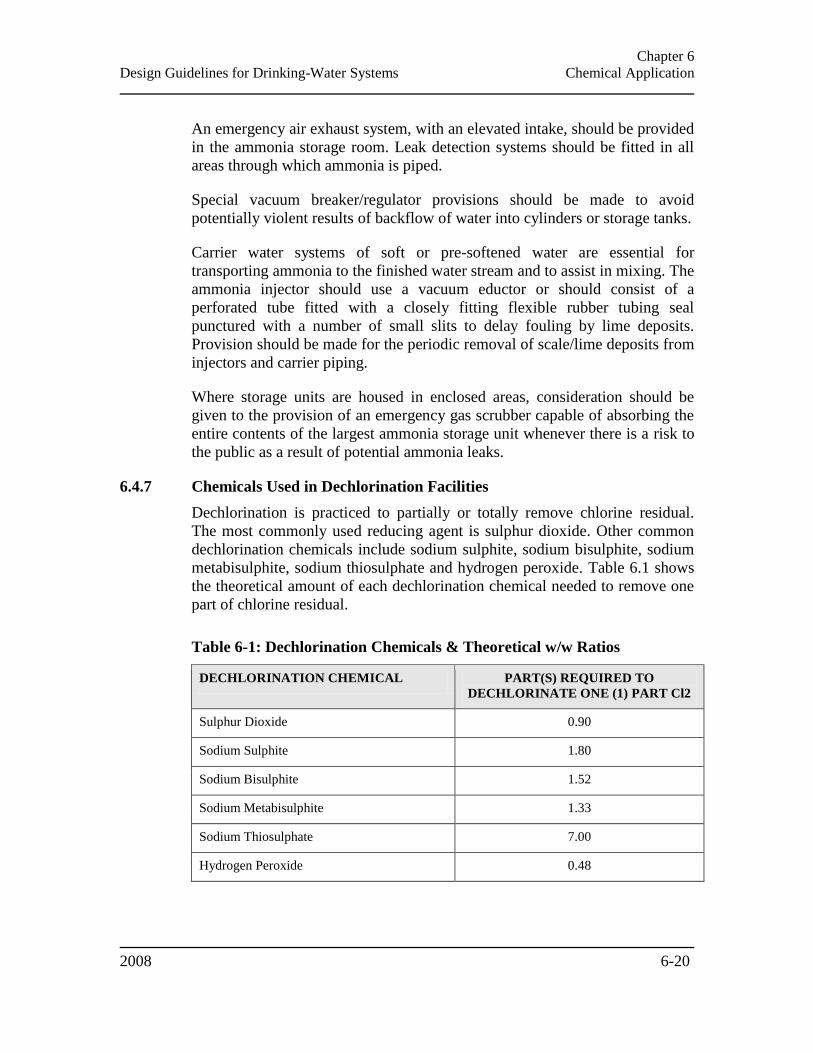
Chapter 6
Design Guidelines for Drinking-Water Systems Chemical Application
2008 6-20
An emergency air exhaust system, with an elevated intake, should be provided
in the ammonia storage room. Leak detection systems should be fitted in all
areas through which ammonia is piped.
Special vacuum breaker/regulator provisions should be made to avoid
potentially violent results of backflow of water into cylinders or storage tanks.
Carrier water systems of soft or pre-softened water are essential for
transporting ammonia to the finished water stream and to assist in mixing. The
ammonia injector should use a vacuum eductor or should consist of a
perforated tube fitted with a closely fitting flexible rubber tubing seal
punctured with a number of small slits to delay fouling by lime deposits.
Provision should be made for the periodic removal of scale/lime deposits from
injectors and carrier piping.
Where storage units are housed in enclosed areas, consideration should be
given to the provision of an emergency gas scrubber capable of absorbing the
entire contents of the largest ammonia storage unit whenever there is a risk to
the public as a result of potential ammonia leaks.
6.4.7 Chemicals Used in Dechlorination Facilities
Dechlorination is practiced to partially or totally remove chlorine residual.
The most commonly used reducing agent is sulphur dioxide. Other common
dechlorination chemicals include sodium sulphite, sodium bisulphite, sodium
metabisulphite, sodium thiosulphate and hydrogen peroxide. Table 6.1 shows
the theoretical amount of each dechlorination chemical needed to remove one
part of chlorine residual.
Table 6-1: Dechlorination Chemicals & Theoretical w/w Ratios
DECHLORINATION CHEMICAL PART(S) REQUIRED TO
DECHLORINATE ONE (1) PART Cl2
Sulphur Dioxide 0.90
Sodium Sulphite 1.80
Sodium Bisulphite 1.52
Sodium Metabisulphite 1.33
Sodium Thiosulphate 7.00
Hydrogen Peroxide 0.48

Chapter 6
Design Guidelines for Drinking-Water Systems Chemical Application
2008 6-21
Gaseous storage facilities may house gaseous sulphur dioxide for
dechlorination requirements. Most precautions for gaseous chlorine (Section
6.4.2 – Chlorine Gas) will also apply for sulphur dioxide. The designer should
consult the manufacturer for specific details regarding storage and handling
requirements for sulphur dioxide and other reducing agents used for
dechlorination.
Guidance on dechlorination can be found in the AWWA Manual of Water
Supply Practices M20 – Water Chlorination/Chloramination Practices and
Principles, and the AwwaRF report Guidance Manual for Disposal of
Chlorinated Water (Project #2513).
6.4.8 Acids & Bases
Strong acids and bases should be stored in separate areas. Concentrated acids
and bases should be kept in closed corrosion-resistant shipping containers or
storage units. Acids and bases should not be handled in open vessels, but
should be pumped in undiluted form from original containers through suitable
hose to a dilution tank, or where dilution is not required to aid process control,
to the point of treatment or to a covered day tank. Separate ventilation systems
may be required for areas where concentrated acids or bases are stored.
6.4.9 Ozone
6.4.9.1 General
Ozone is an unstable and very powerful oxidant and needs to be generated
electrically on-site.
For small systems, very simple, low maintenance pre-engineered treatment
units producing ozone from ambient air at up to a very few grams of ozone
per hour are used.
For taste and odour control, and for primary disinfection, larger outputs of
ozone are generally required using proprietary equipment. The designer
should consult the manufacturer for power, air-feed, cooling and temperature
requirements, as well as contactor design and ozone destructor requirements.
Additional guidance for the design of large scale ozonation systems is
provided in the Ten States Standards.
High purity oxygen used as feed gas can be purchased and stored as a liquid
(LOX), or it can be generated on-site through either a cryogenic process,
vacuum swing adsorption (VSA) or pressure swing adsorption (PSA).
Cryogenic generation of oxygen is a complicated process and should only be
considered for large systems. Storage of LOX is governed by regulations in

Chapter 6
Design Guidelines for Drinking-Water Systems Chemical Application
2008 6-22
building and fire codes. These regulations will impact the space requirements
and may dictate the construction materials of adjacent structures.
The generators can be low, medium or high frequency type. Specifications
should require that the transformers, electronic circuitry and other electrical
hardware be proven, high quality components designed for ozone service.
Appropriate ozone generator backup equipment should be provided.
Only low carbon 304L or 316L grade stainless steel piping should be used for
ozone service with 316L being the preferred material. Connections on piping
used for ozone services should be welded, where possible. Connections with
meters, valves or other equipment are to be made with flanged joints with
ozone resistant gaskets, such as TeflonTM
or HypalonTM
. Screwed fittings
should not be used because of their tendency to leak.
Ozone monitors should be installed to measure ozone concentration on both
the feed gas and off-gas from the contactor and in the off-gas from the
destruct unit. For disinfection systems, monitors should also be provided for
monitoring ozone residuals in the water. The number and location of ozone
residual monitors should be such that the amount of time that the water is in
contact with the ozone residual can be determined.
A minimum of one ambient ozone monitor should be installed in the vicinity
of the contactor and a minimum of one should be installed in the vicinity of
the generator. Ozone monitors should also be installed in any areas where
ozone gas may accumulate. Ambient ozone exposure levels are governed by
the Occupational Health and Safety Act (OHSA).
6.4.9.2 Ozone Contactors
The specific process objective should dictate contact basin design. Reactions
that are rapid relative to the ozone mass transfer rate from gas to liquid phase
are best served by contactors that promote the maximum transfer of ozone in
the shortest period of time. For these applications, such as oxidation or iron,
manganese or simple organics, contact time is often less important and
contactors that rely on single points of application may be suitable. For
reactions that are slow relative to the ozone mass transfer rate, such as
disinfection or oxidation of complex organics (such as herbicides or
pesticides), contact time is critical and favours contactors with extended
detention time and multiple application points, such as the conventional multi-
stage fine bubble diffuser design.
The types of contactors that are commonly used include:
Conventional fine bubble
Chapter 6
Design Guidelines for Drinking-Water Systems Chemical Application
2008 6-23
Turbine
Packed column
Injectors
Deep U-tube
Bubble Diffusers
The most common design is a multichamber over-under baffled contactor with
ozone addition to the first one or two chambers via diffusers situated at the
bottom of the chambers. Where disinfection is the primary application, a
minimum of two contact chambers each equipped with baffles to prevent short
circuiting and induce counter-current flow should be provided. The water
depth in the contactor is typically between 4.6 and 6 m (15 and 20 ft) to
achieve high transfer efficiency of the added ozone.
Once the immediate or initial ozone demand has been satisfied and a residual
ozone level has been maintained in contactor stages, the designer may
consider the provision of a “passive” stage without ozone diffusers, which will
serve to increase the required retention time without the cost of the additional
diffusers and associated piping.
The contactor should be designed to ensure good flow dispersion and to avoid
short-circuiting. The diffusion system should optimize liquid/gas contact and
maximize mass transfer. For optimum ozone transfer efficiency, gas bubble
size should be between 2 and 5 mm (0.08 and 0.2 in).
Ozone should be applied using porous tube or dome diffusers. For ozone
applications in which precipitates are formed, such as with iron and
manganese removal, porous tube diffusers are not recommended. Dome
diffusers are generally preferred as they produce finer bubbles. Due to head
loss limitations, proprietary diffusers typically have a maximum gas flow
rating that should not be exceeded. The chamber floor area should therefore
be large enough to accommodate the minimum number of diffusers.
Contactors should be separate closed vessels that have no common walls with
adjacent rooms. The contactor should be kept under negative pressure and
ozone monitors should be provided to protect worker safety. Placement of the
contactor where the entire roof is exposed to the open atmosphere is
recommended.
Large contact vessels should be made of reinforced concrete. All
reinforcement bars should be covered with a minimum of 38 mm (1.5 in) of
concrete. Smaller contact vessels can be made of stainless steel, fibreglass or
other material which will be stable in the presence of residual ozone and
ozone in the gas phase above the water level.
Chapter 6
Design Guidelines for Drinking-Water Systems Chemical Application
2008 6-24
Multiple sampling ports should be provided to enable sampling of effluent
water in each compartment and to confirm CT calculations.
Contactors should be designed with approximately 1 m (3 ft) of headroom to
provide for unimpeded gas flow to the off-gas exit. Where necessary, a system
should be provided between the contactor and the off-gas destruct unit to
remove froth from the air and return the froth to the contactor or other
acceptable location. If foaming is expected to be excessive, then a potable
water spray system should be placed in the contactor head space.
All contactors should have provisions for cleaning, maintenance and drainage
of the contactor. The basic arrangement of the contactor will establish the
provisions required for personnel access. Stainless steel hatches with ozone-
resistant gaskets should be provided for each contactor stage to minimize
difficulty and delay of entry and exit from the contactor under regular and
emergency conditions. The design should also provide for exhaust ventilation
prior to the entry of maintenance personnel
Other Contactors
Other contactors may be acceptable, provided adequate ozone transfer is
achieved and the required contact times and residuals can be met and verified.
6.4.9.3 Ozone Destruction Unit
A system for treating the final off-gas from each contactor should be provided
in order to meet safety and air quality standards. Acceptable systems include
thermal destruction and thermal/catalytic destruction units.
In order to reduce the risk of fires, the use of units that operate at lower
temperatures is encouraged, especially where high purity oxygen is the feed
gas.
The maximum allowable ozone concentration in the air discharge is 0.1 mg/L
(by volume).
At least two units should be provided which are each capable of handling the
entire gas flow.
Exhaust blowers should be provided in order to draw off-gas from the
contactor into the destruction unit.
Heat exchangers and catalysts should be protected from froth, moisture and
other impurities which may harm the units.
The catalyst and heating elements should be located where they can easily be
reached for maintenance.

Chapter 6
Design Guidelines for Drinking-Water Systems Chemical Application
2008 6-25
6.4.9.4 Alarms
The following alarms/shutdown systems should be considered at each
installation:
Dew point shutdown/alarm – This system should shut down the
generator in the event the system dew point exceeds -60ºC (-76ºF);
Ozone generator cooling water flow shutdown/alarm – This system
should shut down the generator in the event that cooling water flow
decreases to the point that generator damage could occur;
Ozone power supply cooling water flow shutdown/alarm – This system
should shut down the power supply in the event that cooling water flow
decreases to the point that damage could occur to the power supply;
Ozone generator cooling water temperature shutdown/alarm – This
system should shut down the generator if either the inlet or outlet cooling
water exceeds a certain preset temperature;
Ozone power supply cooling water temperature shutdown/alarm –
This system should shut down the power supply if either the inlet or outlet
cooling water exceeds a certain preset temperature;
Ozone generator inlet feed gas temperature shutdown/alarm – This
system should shut down the generator if the feed gas temperature exceeds
a certain preset value;
Ambient ozone concentration shutdown/alarm – The alarm should
sound when the ozone level in the ambient air exceeds 0.1 ppm or a lower
value chosen by the municipality/owner. Ozone generator shutdown
should occur when ambient ozone levels exceed 0.3 mg/L (or a lower
value) either in the vicinity of the ozone generator or the contactor; and
Ozone destruct temperature alarm – The alarm should sound when
temperature exceeds a preset value.
6.4.10 Hydrogen Peroxide
Advanced oxidation processes using a combination of peroxide and ozone or
peroxide and UV have been developed which require a hydrogen peroxide
feed system and an ozone generation or UV system. For AOPs using ozone,
hydrogen peroxide can be added upstream or downstream of ozone, or
simultaneously. Where UV is used, peroxide is added either upstream or
simultaneously with UV. Ozone generation systems are discussed in Section
6.4.9 – Ozone. Design considerations for UV systems are discussed in Section
Chapter 6
Design Guidelines for Drinking-Water Systems Chemical Application
2008 6-26
5.9.5 – Ultraviolet Light Inactivation. Peroxide removal should be
accomplished before the application of chlorine.
Peroxide is a strong oxidant and contact with personnel should be avoided.
Secondary containment should be provided for storage tanks to contain any
spills. Dual containment piping should be considered to minimize the risk of
exposure to plant personnel.
Peroxide can be stored in high density polyethylene or 304L or 316L grade
stainless steel drums or tanks. Peroxide can be stored on-site but deteriorates
gradually over time. Peroxide deteriorates rapidly if contaminated and with
heat or exposure to certain materials. Excessive heat may cause a tank rupture
due to gas generation if the tank is not vented properly. Tanks should be
vented according to the manufacturer/supplier specifications. Peroxide has a
lower freezing point than water, however, housing or heat tracing should be
provided for storage tanks and exterior piping if extended periods with
temperatures below freezing are anticipated. Hydrogen peroxide, at
concentrations of 35% and 50%, freezes at temperatures of -40ºC (-40ºF) and
-45ºC (-49ºF) respectively.
Pipes, gaskets and metering pumps should be constructed of peroxide resistant
materials. The designer should ensure that all wetted stainless steel
components are passivated using industry accepted passivation procedures.
Pumps should be designed to prevent potential air binding of peroxide off-gas.
Adequate mixing should be provided. It is recommended that all peroxide
chemical dosing systems be provided with safety relief valves in areas where
hydrogen peroxide can become trapped.
6.4.11 Potassium Permanganate
Potassium permanganate solution decomposes slowly and, as a result, is better
purchased as a granular solid. Potassium permanganate may be supplied in dry
form in buckets, drums and bulk. A concentrated potassium permanganate
solution (1 to 4%) can be generated on-site for water treatment applications.
Depending on the amount of permanganate required, these solutions should be
made up in batch modes, using storage tanks with mixers and a metering
pump for small feed systems. Larger systems should include a dry chemical
feeder, storage hopper and dust collector configured to automatically supply
permanganate to the solution storage tank.
In conventional treatment plants, potassium permanganate solution is added to
the raw water intake, or as far upstream of coagulant addition as possible.
Adequate mixing should be provided. In all cases, potassium permanganate
should be added prior to filtration.
Chapter 6
Design Guidelines for Drinking-Water Systems Chemical Application
2008 6-27
Potassium permanganate solution should be pumped from the solution tank to
the injection point. If the injection point is a pipe, a standard injection nozzle
protruding midway into the pipe section should be used. Injection nozzles can
also be used to supply the solution to mixing chambers and clarifiers. Powered
activated carbon (PAC) and potassium permanganate should not be added
concurrently. PAC should be added downstream of potassium permanganate
because it may adsorb permanganate, rendering it unavailable for the
oxidation of target organics.
6.4.12 Phosphates & Polyphosphates
Stock phosphate solutions should be kept covered and disinfected by
maintaining approximately 10 mg/L chlorine residual. Phosphate solutions
having a pH of 2.0 or less may be exempt from this requirement.
Polyphosphates should not be applied ahead of iron and/or manganese
removal treatment. The point of application should be prior to any aeration,
oxidation or disinfection if no iron or manganese removal treatment is
provided.
Feed and storage equipment should conform to the requirements specified by
the manufacturer.
6.4.13 Powdered Activated Carbon (PAC)
The designer should consider the possibility of powered activated carbon
(PAC) addition at several points within the treatment process. PAC addition
should take place as far upstream of coagulant addition as possible, preferably
with mechanically aided mixing. The designer should avoid feeding
chlorinated water to any form of carbon.
PAC can be added as a premixed slurry or by means of dry feed. Continuous
agitation should be provided to ensure that the PAC does not deposit in the
slurry storage tank.
PAC should be considered as a potentially combustible material and should be
stored in a separate fire retardant building or room equipped with explosion
proof lighting and electrical systems. Wet activated carbon may create an
oxygen-deficient environment in enclosed spaces, therefore, appropriate
safety precautions should be provided. The manufacturer recommendations
regarding storage and handling should be followed.
Provision should be made for adequate dust control. Provisions should also be
made to scrub or filter the carrier air when dry PAC is off-loaded into silos.
Chapter 6
Design Guidelines for Drinking-Water Systems Chemical Application
2008 6-28
6.4.14 Fluoride
Sodium fluoride, hydrofluosilicic acid and sodium silicofluoride may be used
for fluoridation. These compounds are highly corrosive and require specific
considerations. In addition to these guidelines, the designer should refer to a
fluoride manual such as AWWA Manual of Water Supply Practices M4 –
Water Fluoridation Principles and Practices.
Water used for sodium fluoride dissolution should be softened if hardness
exceeds 75 mg/L as calcium carbonate.
For smaller systems, the electrical outlet used for the fluoride feed pump
should have a non-standard receptacle and should be interconnected with the
well or service pump;
Saturators should be of the upflow type and be provided with a meter and
backflow protection on the make-up water pipe.
Construction should be of corrosion resistant material. The use of explosion
proof motors and electrical components should be considered. Light and fan
switches should not be located within the fluoride room.
6.4.15 Carbon Dioxide
Where carbon dioxide is added for pH adjustment, the contact chamber should
provide a detention time sufficient to ensure effective absorption. The
recarbonation basin design should provide:
A total detention time of 20 minutes;
A minimum of two parallel compartments, with a depth that will provide a
diffuser submergence of not less than 2.3 m (7.5 ft) nor greater
submergence than recommended by the manufacturer, as follows:
A mixing compartment having a detention time of at least three
minutes; and
A reaction compartment.
The practice of on-site generation of carbon dioxide is discouraged;
Where liquid carbon dioxide is used, adequate precautions should be taken
to prevent carbon dioxide from entering the plant from the recarbonation
process;
Chapter 6
Design Guidelines for Drinking-Water Systems Chemical Application
2008 6-29
Recarbonation tanks should be located outside or be sealed and vented to
the outside with adequate seals and adequate purge flow of air to ensure
worker safety; and
Provisions should be made for draining the recarbonation basin and
removing sludge.

Chapter 7
Design Guidelines for Drinking-Water Systems Pumping Facilities
2008
CHAPTER 7
PUMPING FACILITIES
7.1 GENERAL .................................................................................................................................... 7-1 7.2 STATION TYPES ......................................................................................................................... 7-1 7.3 GENERAL DESIGN CONSIDERATIONS ................................................................................. 7-1
7.3.1 Firm Capacity & Station Capacity ...................................................................................... 7-1 7.3.2 Site Considerations & Protection ........................................................................................ 7-2 7.3.3 Pumping Wet Wells .............................................................................................................. 7-3 7.3.4 Equipment Servicing ............................................................................................................ 7-4 7.3.5 Stairways &d Ladders ......................................................................................................... 7-4 7.3.6 Heating, Ventilation & Dehumidification ............................................................................ 7-4 7.3.7 Lighting ................................................................................................................................ 7-5 7.3.8 Sanitary & Other Conveniences .......................................................................................... 7-5 7.3.9 Controls ............................................................................................................................... 7-5 7.3.10 Standby Power ................................................................................................................ 7-6 7.3.11 Transformers ................................................................................................................... 7-7 7.3.12 Automatic & Remote Controlled Stations ....................................................................... 7-7 7.3.13 Safety............................................................................................................................... 7-8
7.4 PUMPING CONSIDERATIONS ................................................................................................. 7-8 7.4.1 Raw Water Pumping ............................................................................................................ 7-9 7.4.2 Treated Water Pumping ..................................................................................................... 7-10 7.4.3 Booster Pumping Stations .................................................................................................. 7-10
7.5 PUMPING COSIDERATIONS FOR SYSTEMS SERVING FEWER THAN 500 PEOPLE ..... 7-12 7.5.1 Raw Water Pumping .......................................................................................................... 7-12 7.5.2 Treated Water Pumping ..................................................................................................... 7-12 7.5.3 Pumphouses ....................................................................................................................... 7-13 7.5.4 Controls ............................................................................................................................. 7-13
7.5.4.1 Pressure Tanks ............................................................................................................................. 7-14 7.6 PUMPS & MOTORS .................................................................................................................. 7-15
7.6.1 Suction Lift & Priming....................................................................................................... 7-15 7.6.2 System Head Curves .......................................................................................................... 7-16 7.6.3 Constant Speed versus Variable Speed Pumping Units ..................................................... 7-17 7.6.4 Water Seals ........................................................................................................................ 7-17 7.6.5 Motors & Starters .............................................................................................................. 7-17
7.7 APPURTENANCES ................................................................................................................... 7-17 7.7.1 Valves/ Check Valves ......................................................................................................... 7-17 7.7.2 Gauges & Meters ............................................................................................................... 7-18 7.7.3 Suction & Discharge Piping .............................................................................................. 7-18 7.7.4 Surge Arrestor Systems ...................................................................................................... 7-20

Chapter 7
Design Guidelines for Drinking-Water Systems Pumping Facilities
2008 7-1
CHAPTER 7
PUMPING FACILITIES
The requirements described in this chapter apply to raw and treated water pumping
stations and booster pumping stations. Pumping facilities should be designed to maintain
the quality of pumped water, for example, by minimizing retention time and ensuring
adequate flows and velocities in the distribution system. Appropriate design measures to
help ensure the security of water pumping facilities should also be incorporated (Section
3.24 – Security).
7.1 GENERAL
The design of the pumping station is also governed by a number of acts and
regulations that do not fall under the jurisdiction of the ministry, including but
not limited to Ontario Ministry of Labour regulations, building, electrical, and
fire codes.
Groundwater well pumps and backwash pumping are discussed in Chapter 4 –
Source Development and Chapter 5 – Treatment, respectively. Positive
displacement pumps used for chemical pumping are discussed in Section 6.2.6
– Chemical Feed Equipment and Control.
7.2 STATION TYPES
The three types of pumping facilities addressed in this chapter are raw water
pumping (commonly called low lift pumping), treated water pumping
(commonly called high lift pumping) and booster pumping stations.
Pumping stations commonly use either horizontal centrifugal pumps, vertical
turbine pumps or submersible pumps. Typically, horizontal splitcase
centrifugal pumps are equipped with side suction and side discharge, while
larger units may have bottom suction. Refer to the Hydraulic Institute (HI)
ANSI/HI Pump Standards for appropriate uses of different pump types.
7.3 GENERAL DESIGN CONSIDERATIONS
7.3.1 Firm Capacity & Station Capacity
Raw water pumping stations should be provided with firm capacity, which is
defined as:
Chapter 7
Design Guidelines for Drinking-Water Systems Pumping Facilities
2008 7-2
Capacity of the raw water pumping station able to supply the water
treatment plant design capacity with the largest unit out of service.
Consideration should also be given to other circumstances such as distance
from the water treatment plant and the availability of raw water storage.
Treated water and booster pumping stations should be provided with firm
capacity, which is defined as:
Capacity of the pumping station with the largest unit out of service if the
station supplies a pressure zone with adequate storage available for fire
protection and balancing. Sizing of storage facilities is discussed in
Section 8.4 – Sizing of Storage Facilities; and
Capacity of the pumping station with the two largest units (including the
fire pump[s], if any) out of service if the pumping station serves a pressure
zone that does not have adequate floating storage available and is the sole
source of supply in the area.
Pumping station structures, major piping and appurtenances should be
designed for at least the 20-year estimated flow or if practicable, for the
ultimate service area requirements. Alternatively, the initial design should be
such as to permit expansion to the ultimate capacity. The initial design should
allow for additional pumping units, standby power facilities, transformers, and
other mechanical, electrical and treatment equipment as will be required in
future. Consideration should also be given to the potential consequences of
over-sizing of the initial equipment, especially with respect to metering
devices.
7.3.2 Site Considerations & Protection
System hydraulics, protection against interruption of service by fire, flood,
freezing or any other hazard should also be considered during site selection.
The station should be elevated to a minimum of 1 m (3 ft) above the 100-year
flood elevation, or 1 m (3 ft) above the highest recorded flood elevation,
whichever is higher, or protected to such elevations, unless a hydraulic
analysis is completed to identify a more appropriate elevation. Consideration
should also be given to the requirements of the local Conservation Authority
(http://conservation-ontario.on.ca/).
The station should be readily accessible at all times. To allow for servicing,
vehicle access to the pumping station should be provided. The grade around
the station should lead surface drainage away from the station. The distance
from the pumping station exit, as well as the need for additional exits, is
Chapter 7
Design Guidelines for Drinking-Water Systems Pumping Facilities
2008 7-3
governed by the Building Code (O. Reg. 350/06) made under the Building
Code Act, 1992. Protection to prevent vandalism and entrance by animals or
unauthorized persons should be provided.
Pumping stations should have adequate space for the safe servicing of all
equipment. Stations should be of durable construction, fire and weather
resistant and have outward-opening doors. Where permitted by code, inward
opening doors may be considered. Floor elevation should be at least 150 mm
(6 in) above finished grade. The underground structure should be
waterproofed. All floors should slope to a suitable drain and drain in such a
manner that the pumped water will not be contaminated. Building drains
should be constructed in such a way as to prevent any potential break or
leakage from entering any wet well structure. Building drains should not be
built within water bearing structures. Means for drainage from pump glands
without discharging onto the floor should be provided. A sump pump should
be supplied to ensure that any miscellaneous water entering the station is
removed. Sump pump systems should be alarmed for flood conditions. A vent
or a vent system should be provided for all process related structures (i.e., wet
well). The vents should be equipped with a 180o bend with insect screen at the
outlet. For vents on critical structures, the design should incorporate
solid/liquid protection from entry into the vent by vandalism or sabotage.
If diesel or other fuelled engines are to be used for standby power, the
requirements of Section 9 of the Environmental Protection Act (EPA)must be
satisfied and an application for air approval may be necessary (Section 3.13 –
Emissions of Contaminants to Air). If the isolation from the engine exhaust to
the nearest point of impingement is not sufficient to dissipate the air
contaminants to within the regulated levels, an exhaust stack may be required.
Any electrical controls, switch gear, or transformers located outside the
pumping station should be properly housed and fenced in accordance with the
local hydro requirements.
7.3.3 Pumping Wet Wells
The floor should be sloped to a sump for easy cleaning and draining. The well
should be covered and protected from contamination. Well access routes
should be adequately sealed against liquid penetration. A 100 mm (4 in) curb
should surround any floor openings to prevent floor drainage entering the well
and the well should be adequately vented. The wet well should be designed
with two pumping compartments or other means to allow the well to be taken
out of service for inspection, maintenance or repair, while still maintaining a
portion of the station capacity in service.
Chapter 7
Design Guidelines for Drinking-Water Systems Pumping Facilities
2008 7-4
The design of the wet well will depend substantially on the number, type and
size of the pumps required. The design should conform to the
recommendations of the Hydraulic Institute standard ANSI/HI 9.8-1998 Pump
Intake Design.
7.3.4 Equipment Servicing
Minimum spacing around pumps, piping, and fittings should comply with the
requirements of the Building Code (O. Reg. 350/06) made under the Building
Code Act, 1992, and the ANSI/HI Pump Standards. Pumping stations should
be provided with lifting devices such as crane-ways, hoist beams, eyebolts or
other facilities for servicing or removal of pumps, motors, valves, piping or
other heavy equipment without the need for heavy manual labour and with
minimum disturbance to the system. Cranes and any other lifting devices
should be rated to a capacity exceeding that of the heaviest equipment unit
anticipated with an appropriate safety margin. Openings in floors, roofs or
wherever else needed should be provided for removal of heavy or bulky
equipment. Such openings should be designed to bear the loads of equipment
traversing them.
A convenient tool board, or other facilities as needed, should be provided for
proper maintenance of the equipment.
7.3.5 Stairways &d Ladders
Stairways or ladders should be provided between all floors and in pits or
compartments which must be entered, or as required by the Building Code (O.
Reg. 350/06) made under the Building Code Act, 1992.
Stairways or ladders should have handrails on both sides and treads of non-
slip material. Stairs are preferred in areas where there is frequent traffic or
where supplies are transported by hand. Stair and tread dimensions should
conform to the requirements of the Building Code (O. Reg. 350/06) made
under the Building Code Act, 1992.
Stainless steel may be considered for submerged conditions.
7.3.6 Heating, Ventilation & Dehumidification
Provisions should be made for adequate heating for the comfort of the
operator and the safe and efficient operation of the equipment. For pumping
stations not occupied by personnel, only enough heat need be provided to
prevent freezing of equipment or treatment processes.
Ventilation should conform to existing local and/or provincial codes.
Adequate ventilation should be provided for all pumping stations for operator

Chapter 7
Design Guidelines for Drinking-Water Systems Pumping Facilities
2008 7-5
comfort and dissipation of excess heat from the equipment. Forced ventilation
of at least six changes of air per hour at the high fan speed and three changes
of air per hour at the low fan speed (regular operation), and manual-off
position should be provided for all confined rooms, compartments, pits and
other enclosures below ground floor, as well as any area where unsafe
atmosphere may develop or where excessive heat build up may occur.
In areas where excess moisture could cause hazards to safety or damage to
equipment, means for dehumidification should be provided.
7.3.7 Lighting
Pumping stations should be adequately lighted throughout. Moisture resistant
lighting should be considered. All electrical work is governed by the
requirements of the Electrical Safety Code, (O. Reg. 164/99) under the
Electricity Act, 1998. More information regarding electrical systems is
provided in Section 3.10 – Electrical Components. Emergency lighting and
illuminated exit signs should be provided at appropriate locations in case of
power failure.
Provision of multiple lighting levels may also be considered for various
duties, such as minimum lighting for walkthroughs and minor checks and
high-level lights for major maintenance.
7.3.8 Sanitary & Other Conveniences
All pumping stations that are staffed for extended periods on a regular basis
should be provided with potable water, lavatory and toilet facilities. Plumbing
should be so installed as to prevent contamination of a public water supply.
Sanitary wastes should be discharged in accordance with Section 3.27 – Water
Treatment Plant Residuals and Sanitary Waste.
Eyewash and safety showers should be provided where potentially harmful
chemicals are present in the pumping facility.
7.3.9 Controls
Pumps, their prime movers and accessories should be controlled to ensure that
they will operate in such a manner that will prevent motor overload. Control
systems should limit the number of start/stop sequences (according to the
pump and electrical equipment manufacturer recommendations) and prevent
coincidental simultaneous starting of numerous pumps. Where duplicate
pumps are installed, provision should be made for alternation of service
cycles. Provision should be made to prevent energizing the motor in the event
of a backspin cycle. Electrical controls should be located above grade.
Equipment should be provided, or other arrangements made, to prevent
Chapter 7
Design Guidelines for Drinking-Water Systems Pumping Facilities
2008 7-6
hydraulic surge pressure from activating controls which switch on pumps or
activate other equipment outside the normal design cycle of operation.
The type of control for pump operation is an important consideration for pump
specification and selection, and will depend on whether the pump(s) are part
of an open or closed pumping system.
In closed systems (treated water, booster pumping), a control valve (not
normally supplied by the pump manufacturer) should be provided to ensure
proper operation of the pump. An air release valve should also be provided in
the pump discharge to let the air out of the discharge pipe at pump start-up.
Pressure control is commonly used for pump operation in both open systems
and closed systems. However, care must be taken for pump selection when
this type of control is used as it can have a significant effect on the operation
of a pump, specifically, the designer should aim to select a process pump
characterized with a steep flow rate versus total dynamic head curve (pump
curve) or ensure that the pump does not operate on the flat part of the curve. A
combination of flow control and pressure control may be used in smaller
systems. Temperature and level sensing controls may also be required.
Whatever control system is utilized, operation of the pumps near their
maximum efficiency points should be maintained.
An adequately sized pressure relief by-pass may be required to minimize
pump cycling and prevent pump damage for pumps operating in the shut-off
head condition. More information regarding pump control systems and
automation is provided in Section 9.6 – Automated/ Unattended Operation.
7.3.10 Standby Power
Dedicated standby power is required to ensure that water may be treated
and/or pumped to the distribution system during power outages to meet the
average day demand. Alternatives to dedicated standby power may be
considered with proper justification.
The need for standby power and the extent of equipment requiring operation
by standby power should be individually assessed for each treatment plant
(Section 3.12 – Standby Power).
The following approach should be adopted:
In cases where no or inadequately sized floating storage is available for
fire protection, it is recommended that full standby power be supplied.
Typically, the size of the pumping stations in these instances is small and
the standby power requirements low. As a result, it is normally the most
Chapter 7
Design Guidelines for Drinking-Water Systems Pumping Facilities
2008 7-7
economical approach to use standby diesel or natural gas generator sets;
and
Where adequate floating storage is available, the need to utilize standby
power is less critical. A common approach is to provide sufficient standby
power for the pump capacity equal to the average day demand rate. This
should supply adequate quantities of water required in the event of a major
power outage.
If standby power is required, it should be provided by means of an emergency
standby generator set preferably; for small systems, a direct drive engine may
be acceptable. The designer is referred to the AWWA Emergency Power
Source Planning for Water and Wastewater publication
The fuel storage and fuel lines should be designed to protect the water supply
from contamination (Section 3.12.1 – Diesel Fuel Storage) and in accordance
with applicable Ontario regulations which govern the design and installation
of fuel storage tanks.
Carbon monoxide detectors with audible alarms should be provided when
generators are housed within pumping stations. Sound studies may be required
to ensure that the operation of standby power equipment does not exceed
ambient noise level limits. In some cases, noise attenuation measures may be
required.
If the generator and motor are not sized to simultaneously run all equipment in
the pumping station, non-essential equipment should be on separate power
circuits which are not energized by the standby power unit.
7.3.11 Transformers
Suitable transformers should be supplied to meet all requirements in the
pumping station. For larger pumping stations, it is recommended that either
dual transformers and switchgear be supplied, or standby power be provided,
such that continuous operation of at least half of the pumping station can be
maintained.
7.3.12 Automatic & Remote Controlled Stations
All automatic stations should be provided with automatic alarms which will
report when abnormal conditions or equipment faults occur. All remote
controlled stations should be electrically operated and controlled and should
have signaling apparatus of proven performance. Installation of electrical
equipment is governed by the Electrical Safety Code (O. Reg. 164/99) under
the Electricity Act, 1998.

Chapter 7
Design Guidelines for Drinking-Water Systems Pumping Facilities
2008 7-8
7.3.13 Safety
Stations should be designed in such a manner as to ensure the safety of the
operators and maintenance staff in accordance with the Confined Spaces
Regulation (O.Reg. 632/05) made under the Occupational Health and Safety
Act (OHSA). Typically, the following points should be considered:
Any moving equipment should be covered with suitable guards to prevent
accidental contact;
Equipment that starts automatically should be suitably signed to ensure
that operators are aware of this situation;
Local lockouts on all equipment should be supplied so that maintenance
personnel can ensure that they are completely out of service;
Local emergency stops should be provided;
Provision of fire/smoke detectors, fire extinguishers and sprinkler systems
(where appropriate);
All stairways and walkways should be properly designed with guardrails;
and
Minimizing confined spaces, where applicable.
More detailed information regarding safety should be obtained from the
Ontario Ministry of Labour.
7.4 PUMPING CONSIDERATIONS
Pumps should be specified so that the full range of flows anticipated can be
provided with pumps operating in the vicinity of their optimum efficiency
points, with due regard to the hydraulic design of the discharge piping. This is
often accomplished by selecting pumps which have wide band efficiencies
and an appropriate operating curve.
The number of pumps should be consistent with the pattern of flow required
and the method of flow control. It is recommended that at least three pumps
be provided for operating flexibility; a minimum of two pumps is required,
one as a redundant standby, with consideration of firm capacity of the
pumping station (Section 7.3.1 – Firm Capacity and Station Capacity).
The station design should allow for future additional pump units and where
possible, the piping should be large enough for an increase in pump size to be
Chapter 7
Design Guidelines for Drinking-Water Systems Pumping Facilities
2008 7-9
accommodated. Adequate space should be provided for the installation of
these additional units and to allow safe servicing of all equipment.
The pumping station design should provide for flooded suctions at all times,
otherwise, an adequate priming system should be provided with sufficient
capacity to prime pumps within a short period, i.e., 1 to 2 minutes, as
recommended by the pump manufacturer. To accomplish this, the designer
should carefully review potential operating levels of wet wells or storage
reservoirs and pump elevations.
Pumps should be selected which have maximum efficiencies at the average
head condition, but which can meet the maximum flow and pressure
conditions. Particular attention should be paid to pump suction piping design
to ensure net positive suction head (NPSH) available exceeds pump
specifications with respect to NPSH required to avoid cavitation.
Adequate control should be provided which is capable of controlling pump
operation over the entire range of flows expected. Where this is accomplished
by control valves, the valves should be located on the pump discharge to
maintain stable control and avoid cavitation. Other more energy efficient
types of control, such as variable frequency drive systems, may be preferable
provided that they allow for stable pump control. Alternatively, multiple
pumps of different sizes or variable capacities may be provided to cover the
expected range of flows and to ensure that they operate at their optimal
efficiencies.
Large water systems (raw and treated) typically operate using pressure (level)
control. For small water supply systems, where substantial seasonal variations
in flow exist, it may be necessary to provide duplicate flow and pressure pump
control systems – one suitable for very low flows (which normally occur in
winter) and one suitable for the design maximum flows.
Pumping station headers should be adequately protected from transient
pressure surges which may occur if pumps stop on power failure. Protection
may be provided either by appropriate valves or hydraulic transient surge
tanks. If pump discharge valves are provided, they should be slow acting type
and properly controlled to avoid high transient pressures in the system on
opening or closing. These valves should be interlocked with the pump
operation to provide such protection (Section 7.7.4 – Surge Arrestor Systems).
7.4.1 Raw Water Pumping
For raw water pumping stations remote from the treatment plant, the designer
should consider the use of slow opening pump discharge valves to minimize
hydraulic transients.

Chapter 7
Design Guidelines for Drinking-Water Systems Pumping Facilities
2008 7-10
The raw water wet well should be provided with an overflow of sufficient size
or adequate surge volume to handle intake surges which occur on power
failure (when all pumps stop). When designing to handle intake surge, a
minimum Hazen-Williams coefficient of one hundred and fifty (C =150)
should be applied. All electrical equipment and pump motors, except for
immersible and submersible pumps, should be located above the surge water
level.
Provisions should be made to prevent downsurge during hydraulic transients
after power failure, which may cause problems if pump suctions become
exposed and air becomes entrapped in the raw water pump suction piping.
7.4.2 Treated Water Pumping
The minimum number of pumps to be provided is two, in addition to any
pumps required to provide fire flows. The minimum capacity should be equal
to the maximum day demand and the actual capacity will be dictated by the
distribution system and storage design and capacities. In each case, the firm
capacity should be equal to or greater than the design capacity required. In
case of vertical turbine pumps, the pump intake should be deeper than the
lowest reservoir operating level and air release valves should be installed on
the pump discharge.
Where backwash pumps draw from the same well as treated water pumps, the
variations in well level and consequent variations in suction requirements
should be considered when selecting the backwash pumps.
7.4.3 Booster Pumping Stations
The purpose of booster pumping stations is to maintain adequate pressures
and flows in water distribution systems as a result of both changes in ground
elevation and distance from the source of supply. This section addresses
booster pumping stations of the two most common types: without associated
storage for the service area (in-line), and with associated storage.
Booster pumping stations should be designed to service specific areas of a
water distribution system based on defined limits. These areas are generally
isolated from the remainder of the system by control valves.
Booster pumping stations may have incorporated with part of their operation,
elevated or ground storage reservoirs which will serve to supply extreme
demands, such as peak hour, fire flow and other emergency requirements.
Pumps taking suction from ground level storage tanks should be designed
with adequate NPSH.
Chapter 7
Design Guidelines for Drinking-Water Systems Pumping Facilities
2008 7-11
Booster pumps should be located or controlled so that automatic shutoff or
low pressure controller maintains at least 140 kPa (20 psi) in the suction line
under all operating conditions. A valve to control the pressure across the
pump should be considered if suction and discharge pressures vary. Pumps
taking suction from ground level storage facilities should be equipped with
automatic shutoffs or low pressure controllers as recommended by the pump
manufacturer, and the suction piping should be designed to allow for complete
use of the full amount of water in the storage facility. Automatic or remote
control devices should have a range between the start and cutoff pressure, or a
cut off based on the low water level in the storage facility, which will prevent
excessive cycling. A pump bypass should be available and alarms should be
installed for such conditions.
Each booster pumping station should contain not less than two pumps with
capacities such that firm station capacity can be satisfied with the largest
pump out of service. In addition to the other requirements of this section, in-
line booster pumps should be accessible for servicing and repairs.
Booster pumps should not be allowed for any service from the public water
supply main, unless owned and operated by the water authority or if an air gap
or backflow preventer upstream of the booster pump is provided.
Booster pumping stations, either alone or in conjunction with storage, should
be capable of meeting the various demand requirements of the area being
serviced. Analysis should be undertaken to determine each of the following
conditions:
Peak hourly flows when consumption is highest;
Night flows when the consumption rate is at its lowest value and
reservoirs remote from the source of supply are being filled by the booster
station; and
Fire flows which can occur at any time and which must be added to the
maximum day rate.
Discharge pressure from the pumping station should be adequate to ensure
that the pressure in the district to be served is within the range of 275 kPa (40
psi) and 700 kPa (100 psi), during peak and minimum demand periods. In the
case of fire flows, it may be acceptable to allow the pressure in the system to
drop to a level no lower than 140 kPa (20 psi).
If no or inadequate storage is available, the proposed booster pumping station
should be designed in a manner that will allow it to supply all of the extreme
flow conditions mentioned above.
Chapter 7
Design Guidelines for Drinking-Water Systems Pumping Facilities
2008 7-12
Booster pumping stations serving pressure zones with adequate storage should
be designed for the maximum day rate, as it may be cost prohibitive both in
terms of pumping station capacity and watermain design to supply all extreme
flow conditions directly from the booster pumping station (Chapter 8 –
Treated Water Storage).
7.5 PUMPING COSIDERATIONS FOR SYSTEMS SERVING FEWER
THAN 500 PEOPLE
7.5.1 Raw Water Pumping
Where low lift pumps are provided on a surface water source, a minimum of
two units, each capable of the design flow, should be provided.
Low lift pumps should be submersible or vertical turbine and operation of the
pumps should be regulated by high and low water level sensing devices
located in the treated water storage reservoir. Control should be provided for
the low lift raw water pumps to operate singly or together in automatic or
manual modes.
Where filtration with backwash is provided, the low lift pumps should be
controlled so that the discharge rate to the treatment units does not exceed the
capacity of the treatment unit(s) remaining in operation during backwashing
(as applicable). This can be accomplished by either providing sufficient
additional storage at the treatment plant to permit complete shut-down of all
treatment units during the backwash cycle or by installing a rate-of-flow
controller on the low lift pump discharge which throttles/limits flow to the
treatment unit to a capacity equal to that of the unit(s) remaining in service. In
either case, the controls should be connected to the backwash pump cycle for
automatic activation.
Refer to Section 7.4.1 – Raw Water Pumping for more information regarding
raw water pumping.
7.5.2 Treated Water Pumping
Where high lift pumping is necessary, at least two pumps should be provided
with each pump designed to deliver a minimum of the design maximum day
flow at the desired head. In many instances, particularly for smaller systems
with large flow variations, it may be desirable to provide a third domestic high
lift pump with this pump sized to meet a lesser flow than the maximum day
requirement of the system. In this case, this pump should be designed to lead
during lower flow conditions. During normal periods of domestic demand, the
smaller pump would provide an adequate supply of water, while the large
pumps would only operate to accommodate higher demands or in the event of
failure of the lead pump.
Chapter 7
Design Guidelines for Drinking-Water Systems Pumping Facilities
2008 7-13
Where fire protection is to be provided via the communal water
supply/distribution facility, a third high lift pump (fire pump) should be
provided and the capacity of that pump should be at least equal to the
minimum required fire flow.
In instances where the distribution system is not provided with an elevated
storage tank and a ground storage reservoir located at the site of the treatment
facility is the only storage, it may be necessary to provide pump(s) sized for
the peak domestic demand, or maximum day demand plus the required level
of fire flow. In this case, pump operations should be controlled by pressure
switches.
Pressure regulating valves (PRVs) with pressure relief to the storage reservoir
under low demand conditions should be provided for pressure regulation in
the distribution system. In many instances, it may be advisable to provide
pressure tanks for pump control in order to minimize the number of start-stop
cycles and hence, wear and tear, on the pumping equipment.
Refer to Section 7.4.2 – Treated Water Pumping for more information
regarding treated water pumping and Chapter 8 – Treated Water Storage and
Chapter 10 – Distribution System Piping and Appurtenances for distribution
system pressures requirements.
7.5.3 Pumphouses
For each water supply installation, a pumphouse should be constructed. The
designer should refer to all applicable codes and regulations under the
Occupational Health and Safety Act (OSHA), the Building Code Act, 1992
and the Fire Protection and Prevention Act, 1997 and local zoning by-laws.
Refer to Section 7.3 – General Design Considerations for more information
regarding the design of pumping stations.
The design of the pumping station discharge piping should minimize the
number of high points. Any high points in the piping system should be
equipped with a manually operated air release valve which has been threaded
to permit the future installation of an automatic valve should this be found
necessary.
7.5.4 Controls
The following controls may be provided between the storage reservoir and the
high lift and low lift pumping equipment:
A low level set-point to shut-off the high lift and fire pumping equipment
when the water level in the reservoir drops to a pre-determined low level;
Chapter 7
Design Guidelines for Drinking-Water Systems Pumping Facilities
2008 7-14
A high level set-point to shut down the low lift pumps when the water
level in the reservoir has reached a pre-determined high level; and
Level sensors to operate the low lift pumps sequentially.
Pressure switches should be mounted on the discharge line from the high lift
pumping station to operate the high lift pumping equipment sequentially. A
pressure gauge should also be installed on the discharge of each high lift
pump. Elapsed time meters should be provided for all high lift pumps. Output
from the high lift pumping station to the distribution system should be
metered with a recording type flow meter.
The start-stop operation of the fire pump should be arranged between the
municipality/owner and the local fire officials. Indication of the operation
status of the pump should be relayed to a central operating point where 24-
hour surveillance is provided.
Refer to Section 7.3.9 – Controls for more information regarding pumping
system controls.
7.5.4.1 Pressure Tanks
Pressure (hydropneumatic) tanks are used in small closed systems to maintain
acceptable system pressures without the need for frequent stops and starts of
the pumps. They should only be used in very small systems. When
considering the use of pressure tanks, the designer should consider the
implications of loss of pressure in the distribution system in the event of a
power outage or pump failure (i.e., the need to issue a boil water advisory).
Pressure tank storage should not be used for chlorine contact or fire protection
purposes; fire flow requirements are typically provided by by-passing the
pressure tanks. The designer should also consider the impacts of changes in
pressure on the operation of the fire pump(s).
Pressure tanks should meet applicable American Society of Mechanical
Engineers (ASME) code requirements. The maximum allowable working
pressure should be marked on each tank.
Location
Pressure tanks should be located above grade and be completely housed.
Enough space should be provided around the tank for inspection and
maintenance.
Sizing
The capacity of the wells and pumps in a hydropneumatic system should be
equal to the peak instantaneous demand. The active storage volume of the
Chapter 7
Design Guidelines for Drinking-Water Systems Pumping Facilities
2008 7-15
hydropneumatic tanks should be sufficient to limit pump cycling to the
manufacturer recommendations. The maximum cycling frequency should be
determined for the largest pump when consumer demand is half of the
capacity of the largest pump or combination of pumps operated by the same
pressure switch.
Hydropneumatic tanks should only be designed for pump control to minimize
the number of starts, and should never be used as means for providing
disinfectant contact time or storage in any drinking-water system.
Piping
Pressure tanks should have means for isolation to permit operation of the
system while a tank is being repaired or maintained.
Appurtenances
An automatic pressure release valve, mechanical means for adding air,
including an air filter, and sight glass or other tank level indicator should be
provided for maintenance of proper air/water volumes in the pressure tank at
all times.
Control equipment consisting of a pressure gauge and pressure operated start-
stop controls for the pumps should be provided for the pressure tank system.
A shut-off valve should not be installed between the pump and the pressure
operated start-stop controls.
The pressure relieving device should prevent the pressure from rising more
than 10% above the maximum allowable working pressure. The discharge
capacity of the pressure relieving device should be adequately sized. Pressure
gauges should have a range of no less than 1.2 times the pressure at which the
pressure relieving device is set to function.
An access hatch and drain should also be provided. Where practical, the
access hatch should be 600 mm (24 in) in diameter.
7.6 PUMPS & MOTORS
7.6.1 Suction Lift & Priming
Suction lift should be avoided, if possible. If suction lift is necessary, it should
be less than 4.5 m (15 ft) and provisions should be made for priming the
pumps. To avoid pump cavitation, the NPSH required for a selected pump
should be checked against the NPSH available for a given system to ensure
that the latter is greater than the former.
Chapter 7
Design Guidelines for Drinking-Water Systems Pumping Facilities
2008 7-16
Prime water must not be of lesser quality than that of the water being pumped.
Means should be provided to prevent either backpressure or backsiphonage
backflow.
When an air-operated ejector is used, the screened intake should draw clean
air from a point at least 3 m (10 ft) above the ground or other source of
possible contamination. Vacuum priming may be used. Compressed air
systems should be oil-free and filtered to prevent contamination of treated
water.
7.6.2 System Head Curves
The design engineer should determine projected points of operating head and
flow for at least the following conditions:
Average day;
Maximum day;
Peak hour; and
Minimum hour.
Pumps should be selected to ensure that they will operate satisfactorily over
the necessary pumping ranges that can be expected at the pumping station
(including stages of new development and associated water demand increases
in the serviced area). The pumps should be capable of meeting at least the
following criteria:
The rated point which would generally correspond to the maximum day
consumption rate;
The rated point for efficiency evaluation, i.e., the point at which the pump
would normally run and at which the pump should be selected for best
efficiency;
The possible operating range which would be the range over which the
pump must operate from a minimum total dynamic head (TDH) to a
maximum total dynamic head; and
The minimum submergence level in the case of a vertical turbine unit, or
the NPSH required in the case of horizontal centrifugal unit, should also
be specified.
All four of these criteria should be evaluated when a pump is being selected.
The unit should operate at a TDH considerably less than the ultimate rated
Chapter 7
Design Guidelines for Drinking-Water Systems Pumping Facilities
2008 7-17
point (shut-off head). As a result, the maximum efficiency point should be
specified as to be the point at which the pump will normally run.
7.6.3 Constant Speed versus Variable Speed Pumping Units
In certain instances, for pumping stations located in a service area without the
provision of adequate storage and where variations in pressure are critical, it
may be desirable to use variable speed pumps with pressure control to meet
the demand. The provision of variable frequency drives for high lift pumping
is particularly advantageous in drinking water distribution systems with little
or no system storage. Consideration may be given to operating variable and
fixed speed units together to avoid forcing a pump into a shut-off position on
its curve.
7.6.4 Water Seals
Water seals should not be supplied with water of a lesser quality than that of
the water being pumped. Where pumps are sealed with treated water and are
pumping water of lesser quality, either an approved reduced pressure principle
backflow preventer or a break tank open to atmospheric pressure should be
provided. Where a break tank is provided, an air gap of at least 150 mm (6 in)
or two pipe diameters, which ever is greater, should be provided between the
feeder line and the flood rim of the tank.
7.6.5 Motors & Starters
Each pump should be operated by a motor capable of operating the pump at
any point on the head discharge curve. Pump motors over 15 hp should be
certified by the supplier to have undergone standard commercial testing and
be rated as “premium” energy efficient. Motors should be located at such a
level in the pumping station that they can not be flooded. Alternatively,
immersible/submersible motors can be used.
A suitable time delay between pump stop and the subsequent pump start
should be provided to allow the shaft to come to a complete stop. Soft start
motor starters should be considered when standby power is provided.
Staggered pump start is recommended to reduce in-rush load on the generator.
7.7 APPURTENANCES
7.7.1 Valves/ Check Valves
Pumps should be adequately valved to permit satisfactory operation,
maintenance and repair of the equipment. If foot valves are necessary, they
should have a net valve area of at least 2.5 times the area of the suction pipe
and they should be screened. Each pump should have a positive-acting check
valve on the discharge side between the pump and the shut-off valve.
Chapter 7
Design Guidelines for Drinking-Water Systems Pumping Facilities
2008 7-18
Valves, either of the gate or butterfly type, should be used for pump isolation
and control valves (hydraulically activated globe or butterfly) for pump
discharge operation. Typically, on larger installations [i.e., 250 mm (10 in) or
greater], butterfly valves should be used. Gate or ball valves, especially for
suction isolation, may be used for smaller sized piping.
Check valves should be mounted horizontally on pump discharges so that the
valve will close slowly and automatically if station or pump flow stops.
7.7.2 Gauges & Meters
Each pump should have a standard pressure gauge on its discharge line and a
compound gauge on its suction line. Pressure transducers or pressure
indicating transmitters (PITs) for each pump should be provided in larger
stations. Means should be provided for measuring the discharge flow of each
pump. All stations should have flow rate indicating, totalizing and recording
metering of the total water pumped. A magnetic flow meter, an insert Venturi
meter or a mechanical meter may be used for this purpose. Flow meters are
discussed in greater detail in Section 3.18 – Flow Metering. Mercury
containing devices should not be used.
Sufficient space should be provided to ensure the accuracy of the metering
device (for appropriate length of approach piping, consult the manufacturer
recommendations). Valved by-passes should be provided for all meters to
facilitate meter maintenance and calibration.
The designer should take into account the piping and orientation requirements
for meter installation and application specifications. The designer should also
note that air entrainment in process streams can have a negative impact on
meter accuracy and functionality, and should be eliminated through air relief
designs.
7.7.3 Suction & Discharge Piping
Suction and discharge piping should be designed and arranged in a way that
meets the recommendations of the Hydraulic Institute. Piping should be
designed so that the friction losses will be minimized. Piping should have
watertight joints and the contents must not be subject to contamination or
leakage. Piping should be protected against surge or water hammer and
provided with suitable restraints where necessary. Piping should be designed
such that each pump has an individual suction line or that the lines be
manifolded such that they will ensure similar hydraulic and operating
conditions.
Suction and discharge piping should be designed and arranged in such a way
that it is easily accessible, with sufficient room to service all valves, meters
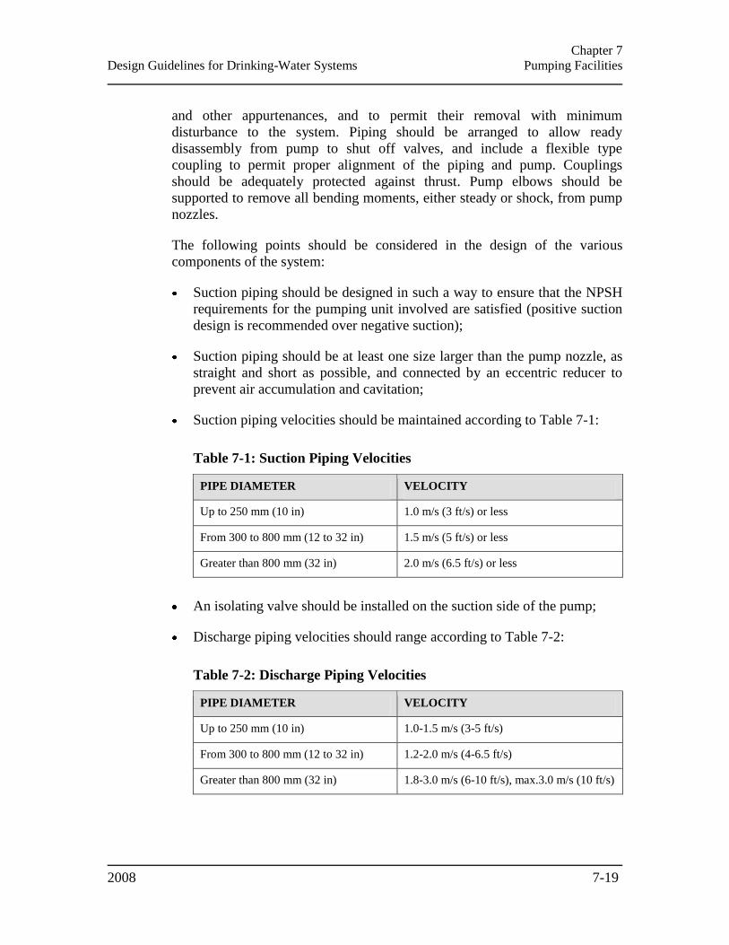
Chapter 7
Design Guidelines for Drinking-Water Systems Pumping Facilities
2008 7-19
and other appurtenances, and to permit their removal with minimum
disturbance to the system. Piping should be arranged to allow ready
disassembly from pump to shut off valves, and include a flexible type
coupling to permit proper alignment of the piping and pump. Couplings
should be adequately protected against thrust. Pump elbows should be
supported to remove all bending moments, either steady or shock, from pump
nozzles.
The following points should be considered in the design of the various
components of the system:
Suction piping should be designed in such a way to ensure that the NPSH
requirements for the pumping unit involved are satisfied (positive suction
design is recommended over negative suction);
Suction piping should be at least one size larger than the pump nozzle, as
straight and short as possible, and connected by an eccentric reducer to
prevent air accumulation and cavitation;
Suction piping velocities should be maintained according to Table 7-1:
Table 7-1: Suction Piping Velocities
PIPE DIAMETER VELOCITY
Up to 250 mm (10 in) 1.0 m/s (3 ft/s) or less
From 300 to 800 mm (12 to 32 in) 1.5 m/s (5 ft/s) or less
Greater than 800 mm (32 in) 2.0 m/s (6.5 ft/s) or less
An isolating valve should be installed on the suction side of the pump;
Discharge piping velocities should range according to Table 7-2:
Table 7-2: Discharge Piping Velocities
PIPE DIAMETER VELOCITY
Up to 250 mm (10 in) 1.0-1.5 m/s (3-5 ft/s)
From 300 to 800 mm (12 to 32 in) 1.2-2.0 m/s (4-6.5 ft/s)
Greater than 800 mm (32 in) 1.8-3.0 m/s (6-10 ft/s), max.3.0 m/s (10 ft/s)
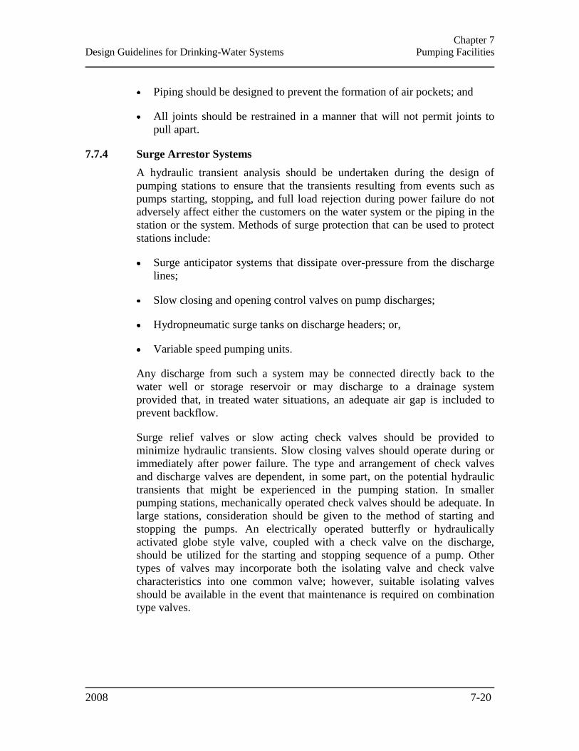
Chapter 7
Design Guidelines for Drinking-Water Systems Pumping Facilities
2008 7-20
Piping should be designed to prevent the formation of air pockets; and
All joints should be restrained in a manner that will not permit joints to
pull apart.
7.7.4 Surge Arrestor Systems
A hydraulic transient analysis should be undertaken during the design of
pumping stations to ensure that the transients resulting from events such as
pumps starting, stopping, and full load rejection during power failure do not
adversely affect either the customers on the water system or the piping in the
station or the system. Methods of surge protection that can be used to protect
stations include:
Surge anticipator systems that dissipate over-pressure from the discharge
lines;
Slow closing and opening control valves on pump discharges;
Hydropneumatic surge tanks on discharge headers; or,
Variable speed pumping units.
Any discharge from such a system may be connected directly back to the
water well or storage reservoir or may discharge to a drainage system
provided that, in treated water situations, an adequate air gap is included to
prevent backflow.
Surge relief valves or slow acting check valves should be provided to
minimize hydraulic transients. Slow closing valves should operate during or
immediately after power failure. The type and arrangement of check valves
and discharge valves are dependent, in some part, on the potential hydraulic
transients that might be experienced in the pumping station. In smaller
pumping stations, mechanically operated check valves should be adequate. In
large stations, consideration should be given to the method of starting and
stopping the pumps. An electrically operated butterfly or hydraulically
activated globe style valve, coupled with a check valve on the discharge,
should be utilized for the starting and stopping sequence of a pump. Other
types of valves may incorporate both the isolating valve and check valve
characteristics into one common valve; however, suitable isolating valves
should be available in the event that maintenance is required on combination
type valves.
Chapter 8
Design Guidelines for Drinking-Water Systems Treated Water Storage
2008
CHAPTER 8
TREATED WATER STORAGE
8.1 GENERAL .................................................................................................................................... 8-1 8.2 TYPES OF TREATED WATER STORAGE FACILITIES .......................................................... 8-1 8.3 PRESSURE CONSIDERATIONS ................................................................................................ 8-2 8.4 SIZING OF STORAGE FACILITIES ........................................................................................... 8-2
8.4.1 Chemical Disinfection Contact & Water Treatment Plant Storage ..................................... 8-3 8.4.2 Sizing Treated Water Storage for Systems Providing Fire Protection ................................ 8-3 8.4.3 Sizing Treated Water Storage for Systems Not Providing Fire Protection .......................... 8-5 8.4.4 Treatment Plant Storage ...................................................................................................... 8-5
8.4.4.1 Filter Wash Water .......................................................................................................................... 8-6 8.4.5 Sizing Considerations for Systems Serving Fewer Than 500 People................................... 8-6
8.5 LOCATION OF STORAGE/ SITE SELECTION CONSIDERATIONS ..................................... 8-6 8.6 SECURITY & PROTECTION ...................................................................................................... 8-7 8.7 CONTROLS & IMPLEMENTATION ......................................................................................... 8-8 8.8 DESIGN CONSIDERATIONS ..................................................................................................... 8-8
8.8.1 Construction Materials ........................................................................................................ 8-8 8.8.2 Maintaining Water Quality .................................................................................................. 8-8
8.8.2.1 Equipment Containing Mercury ..................................................................................................... 8-9 8.8.3 Isolation & Drainage ........................................................................................................... 8-9 8.8.4 Vents .................................................................................................................................. 8-10 8.8.5 Overflow ............................................................................................................................ 8-10 8.8.6 Roof & Sidewall ................................................................................................................. 8-11 8.8.7 Grading .............................................................................................................................. 8-12 8.8.8 Safety ................................................................................................................................. 8-12 8.8.9 Internal Catwalk ................................................................................................................ 8-12 8.8.10 Silt Stop ......................................................................................................................... 8-12 8.8.11 Disinfection & Backflow Prevention ............................................................................. 8-12 8.8.12 Provisions for Sampling ................................................................................................ 8-13 8.8.13 Freezing ........................................................................................................................ 8-13 8.8.14 Access ........................................................................................................................... 8-13 8.8.15 Corrosion Protection .................................................................................................... 8-14
8.9 TREATMENT PLANT STORAGE ............................................................................................ 8-14 8.9.1 Clearwells & Reservoirs .................................................................................................... 8-14 8.9.2 Adjacent Storage ................................................................................................................ 8-14 8.9.3 Other Treatment Plant Storage Facilities.......................................................................... 8-15

Chapter 8
Design Guidelines for Drinking-Water Systems Treated Water Storage
2008 8-1
CHAPTER 8
TREATED WATER STORAGE
This chapter provides guidance for the design of treated water storage in drinking-water
supply systems.
8.1 GENERAL
Treated water storage facilities should be designed to allow maintenance of
adequate flows and pressures in the distribution system during peak hour
water demand, and to meet critical water demands during fire flow and
emergency conditions. Storage volumes should be designed based on
projected design populations.
One of the most important design objectives for water storage is to minimize
the chance of contamination of the treated water. The designer should keep in
mind that the purpose of water storage is to ensure continuity of supply and
maintain system pressure. The materials and designs used for treated water
storage facilities should provide structural stability and durability as well as
preserve the quality of the stored water.
In addition to the information in these guidelines, the designer should refer to
all applicable AWWA Standards which relate to the design of treated water
storage facilities.
8.2 TYPES OF TREATED WATER STORAGE FACILITIES
The following are types of treated water storage facilities:
At the water treatment plant:
Clearwells;
Reservoirs;
Pumping wet wells; and
Pressure tanks.
In the distribution system:
Elevated tanks;
Standpipes; and
Reservoirs.
Chapter 8
Design Guidelines for Drinking-Water Systems Treated Water Storage
2008 8-2
The type(s) of water storage facility (facilities) selected will depend on many
factors such as function, the size of service area, topography, costs, the
balance between water treatment capacity and demand, and the amount of
storage required at the water plant and in the distribution system.
8.3 PRESSURE CONSIDERATIONS
The minimum required water level and the location for a distribution system
storage facility should provide acceptable service pressures throughout the
distribution system as described below and as outlined in Section 10.2 –
Hydraulic Design. System water demands in excess of maximum day
requirements are normally met from storage. Storage facilities should be
designed to maintain adequate pressure in the distribution system at the
average day water demand in the event of a power failure or other emergency.
This lessens the potential for groundwater intrusion and contamination of the
system.
The maximum variation between high and low levels in elevated distribution
system storage tanks should be such that the normal pressures in the
distribution system do not go above 700 kPa (100 psi) nor below 275 kPa (40
psi) during normal demand periods. The normal operating pressure in water
distribution systems should generally be in the range of 350 kPa to 480 kPa
(50 to 70 psi) under maximum daily flow. However, pressures outside of this
range may be dictated by distribution system size and/or topography.
Pressures as low as 140 kPa (20 psi) may be acceptable when fire demands are
experienced in conjunction with maximum day consumption rates. When
static pressures exceed 700 kPa (100 psi), pressure reducing devices should be
provided on mains or service connections in the distribution system.
8.4 SIZING OF STORAGE FACILITIES
Storage facilities should have sufficient capacity, as determined by
engineering studies, to meet water demands that exceed the daily water supply
capacity of the treatment plant and, where fire protection is provided, fire flow
demands. Emergency planning including the provision of stand-by power
would also influence the sizing of storage facilities. The water storage
requirements (exclusive of storage needed for the operation of the water
treatment plant) are described in Section 8.4.2 – Sizing Treated Water Storage
for Systems Providing Fire Protection and Section 8.4.3 – Sizing Treated
Water Storage for Systems Not Providing Fire Protection which follow.
Where appropriate for larger distribution systems, hydraulic and water quality
models should be used for sizing new storage facilities and for selecting
locations for re-chlorination facilities if needed.
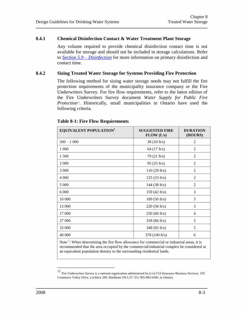
Chapter 8
Design Guidelines for Drinking-Water Systems Treated Water Storage
2008 8-3
8.4.1 Chemical Disinfection Contact & Water Treatment Plant Storage
Any volume required to provide chemical disinfection contact time is not
available for storage and should not be included in storage calculations. Refer
to Section 5.9 – Disinfection for more information on primary disinfection and
contact time.
8.4.2 Sizing Treated Water Storage for Systems Providing Fire Protection
The following method for sizing water storage needs may not fulfill the fire
protection requirements of the municipality insurance company or the Fire
Underwriters Survey. For fire flow requirements, refer to the latest edition of
the Fire Underwriters Survey document Water Supply for Public Fire
Protection12. Historically, small municipalities in Ontario have used the
following criteria.
Table 8-1: Fire Flow Requirements
EQUIVALENT POPULATION1 SUGGESTED FIRE
FLOW (L/s)
DURATION
(HOURS)
500 – 1 000 38 (10 ft/s) 2
1 000 64 (17 ft/s) 2
1 500 79 (21 ft/s) 2
2 000 95 (25 ft/s) 2
3 000 110 (29 ft/s) 2
4 000 125 (33 ft/s) 2
5 000 144 (38 ft/s) 2
6 000 159 (42 ft/s) 3
10 000 189 (50 ft/s) 3
13 000 220 (58 ft/s) 3
17 000 250 (66 ft/s) 4
27 000 318 (84 ft/s) 5
33 000 348 (92 ft/s) 5
40 000 378 (100 ft/s) 6
Note 1: When determining the fire flow allowance for commercial or industrial areas, it is
recommended that the area occupied by the commercial/industrial complex be considered at
an equivalent population density to the surrounding residential lands.
12
Fire Underwriters Survey is a national organization administered by (c/o) CGI Insurance Business Services, 150
Commerce Valley Drive, Lockbox 200, Markham ON L3T 7Z3, 905-882-6300, in Ontario.
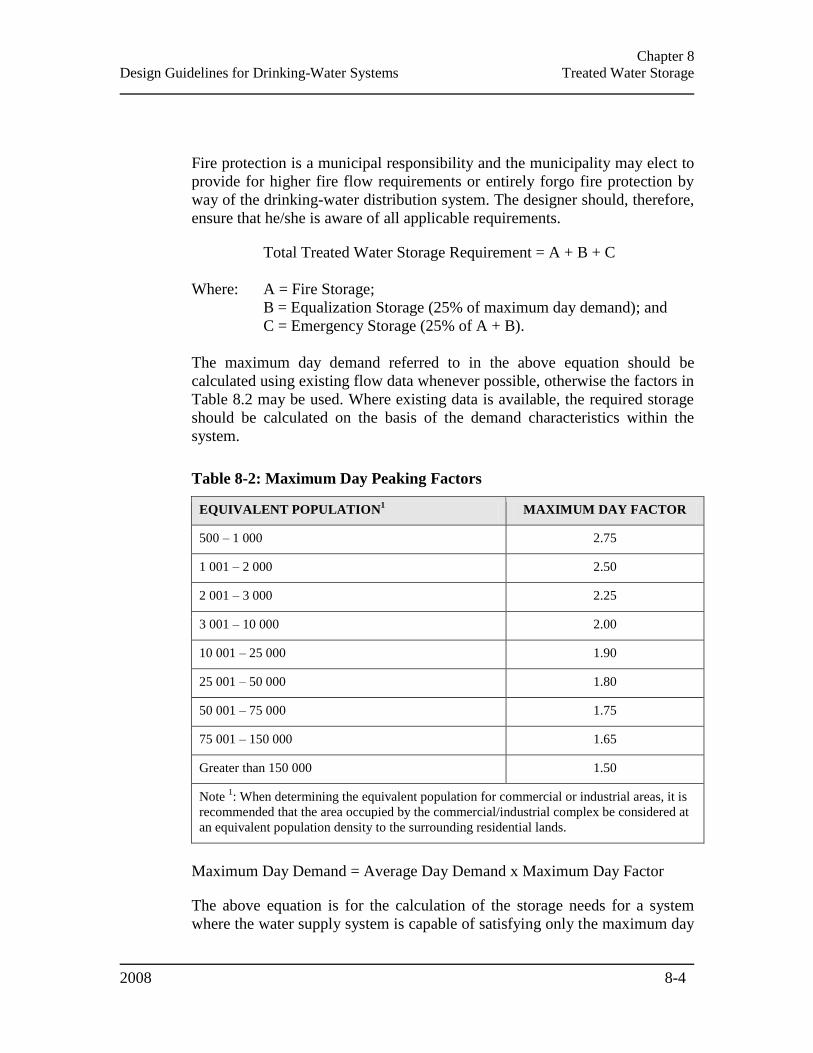
Chapter 8
Design Guidelines for Drinking-Water Systems Treated Water Storage
2008 8-4
Fire protection is a municipal responsibility and the municipality may elect to
provide for higher fire flow requirements or entirely forgo fire protection by
way of the drinking-water distribution system. The designer should, therefore,
ensure that he/she is aware of all applicable requirements.
Total Treated Water Storage Requirement = A + B + C
Where: A = Fire Storage;
B = Equalization Storage (25% of maximum day demand); and
C = Emergency Storage (25% of A + B).
The maximum day demand referred to in the above equation should be
calculated using existing flow data whenever possible, otherwise the factors in
Table 8.2 may be used. Where existing data is available, the required storage
should be calculated on the basis of the demand characteristics within the
system.
Table 8-2: Maximum Day Peaking Factors
EQUIVALENT POPULATION1 MAXIMUM DAY FACTOR
500 – 1 000 2.75
1 001 – 2 000 2.50
2 001 – 3 000 2.25
3 001 – 10 000 2.00
10 001 – 25 000 1.90
25 001 – 50 000 1.80
50 001 – 75 000 1.75
75 001 – 150 000 1.65
Greater than 150 000 1.50
Note 1: When determining the equivalent population for commercial or industrial areas, it is
recommended that the area occupied by the commercial/industrial complex be considered at
an equivalent population density to the surrounding residential lands.
Maximum Day Demand = Average Day Demand x Maximum Day Factor
The above equation is for the calculation of the storage needs for a system
where the water supply system is capable of satisfying only the maximum day
Chapter 8
Design Guidelines for Drinking-Water Systems Treated Water Storage
2008 8-5
demand. For situations where the water supply system can supply more, the
storage requirements can be reduced accordingly.
The physical configuration of the water containing portion of the storage
facility should be such that the equalization volume (B) is located between the
top water level (TWL) of the storage facility and that elevation necessary to
produce a minimum pressure of 275 kPa (40 psi) in the majority of the system
under peak hourly flow. The fire (A) and emergency (C) component volumes
(i.e., A + C) should be located between that elevation necessary to produce
275 kPa (40 psi) under peak hourly flow conditions and that elevation
necessary to produce a minimum 140 kPa (20 psi) under the maximum day
plus fire flow condition.
Should a standpipe with a booster pumping station at the base be proposed,
the equalization volume (B) would normally be located between the TWL and
that elevation necessary to produce 275 kPa (40 psi) in the majority of the
system under peak hourly flow. The fire (A) and emergency (C) components
can be below this 275 kPa (40 psi) elevation provided the booster pump is
designed/sized to increase system pressures to a minimum 140 kPa (20 psi)
under the maximum day plus fire flow condition.
8.4.3 Sizing Treated Water Storage for Systems Not Providing Fire Protection
If the drinking-water system is not being used or will not be used for
providing fire protection, the volume of storage should be 25% of the design
year maximum day plus 40% of the design year average day.
8.4.4 Treatment Plant Storage
Significant storage may be required at water treatment plants for the proper
operation of the plant. This storage is in addition to the storage requirements
described in Section 8.4.2 – Sizing Treated Water Storage for Systems
Providing Fire Protection and Section 8.4.3 – Sizing Treated Water Storage
for Systems Not Providing Fire Protection. Treatment plant storage can be
provided in treated water wet wells, clearwells and/or reservoirs.
The plant storage should be sized (together with distribution system storage
capacity) to minimize on/off cycling of the treated water pumps. Plant storage
should be sized such that distribution system demands and in-plant water use
(e.g., filter washing, chemical systems, and domestic use) can be met while
maintaining relatively constant flow through the plant rather than fluctuating
filtration rates.
Chapter 8
Design Guidelines for Drinking-Water Systems Treated Water Storage
2008 8-6
8.4.4.1 Filter Wash Water
Storage for filter wash water should be sized, in conjunction with backwash
pump units and treated water storage, to provide adequate backwash water (
Section 5.6.2 – Rapid Rate Gravity Filters and Section 5.7.2 – Membrane
Filtration). Consideration should be given to the consequences of
backwashing of several filters in rapid succession and/or worst case conditions
when peak demand and backwash water requirements coincide.
8.4.5 Sizing Considerations for Systems Serving Fewer Than 500 People
If the system municipality/owner has decided that fire protection is not to be
provided and the source is only capable of the maximum day, the minimum
effective storage to be provided should be the average daily flow. Appropriate
allowances for lawn watering and in-plant process requirements, as needed
should be added to the minimum volume.
Where it has been decided that fire protection is to be provided via the
communal water supply and distribution system, the minimum volume of the
storage facility should be increased by an amount equal to the minimum fire
flow for two hours. The allowance for lawn watering is not needed where fire
protection is provided via the communal water supply and distribution system.
In sizing storage facilities for small systems, the designer should also consider
the importance of maintaining water quality, preventing freezing during the
winter and excessive warming of the water during the summer.
8.5 LOCATION OF STORAGE/ SITE SELECTION CONSIDERATIONS
The following factors should be considered in choosing a location for
distribution system storage:
The relationship of distribution system hydraulics (including topography)
and water demands in various parts of the system;
Pumping and transmission costs;
Safety considerations;
Aesthetic considerations and public property owner acceptance;
Future expansion; and
Site access.
A location in an area of the highest water demand and/or low pressure should
be preferred. Storage facilities should ideally be located on the highest point
Chapter 8
Design Guidelines for Drinking-Water Systems Treated Water Storage
2008 8-7
of ground in the area. For large distribution systems, the placement of one
storage tank at central location should be evaluated against smaller units with
equivalent total volume in other parts of the system. The designer should be
aware that flow reversals may create sediment uptake and dispersal. This may
be a more significant issue where the storage tank is located at an extremity of
the distribution system.
In addition, the following factors should be considered in choosing a location
for ground-level or buried reservoirs:
Structural costs based on soil conditions and location of the groundwater
table (the bottom of the reservoir should ideally be above the groundwater
table, or alternatively site drainage should be provided);
Where groundwater levels have the potential to cause floating, structural
measures to prevent floating should be incorporated in the design;
Excavation costs based on cut and fill considerations; and
Any opening in the reservoir should not be less than 600 mm (24 in) above
the original ground level or the level of the 100 year flood (or the highest
flood of record).
Sewers, drains, septic tanks and tile fields, standing water and similar
potential sources of contamination should be kept at least 15 m (50 ft) away
from the reservoir. Where this separation cannot be obtained, sewers
constructed of watermain quality pipe, pressure tested in place at a pressure of
350 kPa (50 psi) without leakage may be used at distances greater than 6 m
(20 ft) in accordance with the Ontario Ministry of Transportation Ontario
Provincial Standard Specification 701 (OPSS 701) of the Ontario Provincial
Standards for Roads and Public Works (OPS).
8.6 SECURITY & PROTECTION
All existing and future water storage structures should be completely covered
and watertight to prevent contamination. Any openings should have covers to
prevent the entry of birds, animals, insects, runoff and excessive dust. The
installation of additional equipment such as antennae should not affect internal
coatings or compromise water quality.
Where pipelines are located underneath or close to a reservoir, the use of rigid
pipe or pipe with adequate joint flexibility is recommended to minimize
potential damage due to differential settling or movement of the reservoir.
Chapter 8
Design Guidelines for Drinking-Water Systems Treated Water Storage
2008 8-8
Fencing or other security measures, as well as locks on valve and vent
housings and access hatches, should be provided at the storage site along with
other precautions (e.g., alarms) to guard against illegal entry, vandalism and
sabotage. The designer should consult the AWWA Security Guidance for
Water Utilities document.
8.7 CONTROLS & IMPLEMENTATION
Adequate instrumentation to control water levels in storage facilities should be
provided. Level indicating devices should provide readings at a central
location and overflow and low-level alarms, activated by separate and
independent devices, should sound at location(s) which will be monitored 24
hours a day. Local level indicators should be provided by a pressure gauge on
the tank piping, a level indicating transmitter or other means. For elevated
tanks, level control instrumentation should be sufficiently precise to prevent
wasting storage or tank overflows.
High lift and/or booster pumps should be designed to operate to maintain
storage facility water levels within a range to maintain adequate distribution
system pressure. Altitude valves or equivalent controls should be installed on
elevated storage when more than one tank is required within a single supply
pressure zone or where the storage facility would overflow at allowable high
distribution system pressure.
8.8 DESIGN CONSIDERATIONS
8.8.1 Construction Materials
All chemicals and water contacting materials used in the construction and
operation of drinking-water systems should meet all applicable quality
standards as described in Section 3.26 – Chemicals and Other Water
Contacting Materials.
The use of concrete form release agents that contain diesel oil or other
potential water tainting components should be avoided.
Designers should be aware that concrete spalling has seriously damaged water
saturated concrete during the freeze/thaw cycles that are typical in Ontario.
8.8.2 Maintaining Water Quality
Stagnation and excessive retention time in the distribution system may result
in a deterioration of water quality. The deterioration may be indicated by loss
of disinfectant residual, formation of disinfection by-products and bacterial re-
growth. Therefore, storage facilities should be designed to prevent stagnation
and minimize detention times. This may be assisted by providing separate
Chapter 8
Design Guidelines for Drinking-Water Systems Treated Water Storage
2008 8-9
inlet and outlet piping, a two-cell design, baffle walls, diffusers and/or by
strategic location of the inlet and outlet piping. Where there is more than one
cell, the inlet should be to one cell and the outlet from another. It should be
possible to operate with one cell out of service. In standpipes where only the
upper portion of the stored water provides useful system pressure, the water
should be circulated through the storage facility to maintain quality and
minimize ice formation. For smaller systems, circulation may be required to
prevent high water temperatures.
If it is not possible to have sufficient turnover of water in a storage facility to
maintain water quality, a pumped recirculation system should be provided and
a booster disinfection system may be required.
Water quality deterioration in storage may be particularly rapid where
sequestering agents are used with hard water or where natural organics react
rapidly with a free chlorine residual. In such cases, the use of monochloramine
as the secondary disinfectant should be considered by the designer. The
designer may also consider the provision of re-chlorination systems at storage
facilities in order to maintain acceptable chlorine residuals. Refer to Section
5.9 - Disinfection for more information on secondary disinfection.
The designer should refer to a publication such as the AwwaRF report
Maintaining Water Quality in Finished Water Storage Facilities (Project
#254).
8.8.2.1 Equipment Containing Mercury
Except for UV lamps, equipment containing mercury should not be used
within a drinking-water system. UV systems should be designed to protect the
water from mercury contamination. Refer to Section 5.9 - Disinfection for
more information on UV systems.
8.8.3 Isolation & Drainage
The system should be designed to ensure that pressure can be maintained even
when the storage facilities are drained for cleaning and maintenance.
Consideration should be given to the installation of air release/vacuum relief
valves on the distribution side of the isolation valve(s).
The storage facility drain should discharge to the ground surface with no
direct connection to a sewer or storm drain. If a connection to a sewer or
storm drain is unavoidable, an atmospheric gap of twice the drain diameter
should be provided.
Floors should be sloped towards the sump to facilitate cleaning.

Chapter 8
Design Guidelines for Drinking-Water Systems Treated Water Storage
2008 8-10
All buried reservoirs should be designed with two or more cells which can be
operated independently, and a separate wet well when applicable. Through
valving it should be possible to isolate one of the two cells without affecting
the operation of the other cell. Two cells can often be provided as a result of
construction phasing requirements.
8.8.4 Vents
Treated water storage facilities should be vented. The overflow pipe should
not be considered a vent. Vents should:
Allow air into the tank at a rate greater than the rate at which water is
withdrawn in order to avoid the development of vacuum/pressure within
the tank;
Prevent the entrance of surface water and rainwater;
Exclude birds and animals;
Exclude insects and dust, as much as this function can be made compatible
with effective venting;
Be located away from areas which will be subject to severe snow drifting;
and
Eliminate entry of solid/liquid agents as a result of vandalism or sabotage.
On ground-level facilities, the vent should terminate in an inverted “U”. The
opening should be 600 to 900 mm (24 to 36 in) above the roof or groundcover
and covered with twenty-four mesh non-corrodible screen. Where a valve
house or pump house is provided, the vents should be located within the
structure.
On elevated tanks and standpipes, vents should open downward and be fitted
with either twenty-four mesh [0.70 mm (0.03 in) openings] non-corrodible
screen or with finer mesh non-corrodible screen in combination with an
automatically resetting pressure-vacuum relief mechanism.
8.8.5 Overflow
All water storage facilities should be provided with an overflow which
discharges 300 to 600 mm (12 to 24 in) above the ground surface over a
drainage outlet structure or a splash pad which drains away from the storage
facility. No overflow should be connected directly to a sewer or storm drain.
If such a connection is unavoidable, an air gap equal to twice the overflow
pipe diameter should be provided. All overflow pipes should be located such
Chapter 8
Design Guidelines for Drinking-Water Systems Treated Water Storage
2008 8-11
that any discharge is visible. Alarms should be installed to alert the operator of
an overflow event.
When an internal overflow pipe is used on elevated tanks, it should be located
in the access tube. On other types of storage facilities, the overflow pipe
should be located on the outside of the structure.
Overflows should open downward and be fitted with twenty-four mesh [0.70
mm (0.03 in) openings] non-corrodible screen. The screen should be installed
within the overflow pipe at a location least susceptible to damage by
vandalism. If a flapper valve is used, the screen should be installed upstream
of the valve. The screen should be located such that it can easily be replaced
following an overflow event.
The overflow pipe should be of sufficient diameter to permit discharge of
water in excess of the maximum potential filling rate.
8.8.6 Roof & Sidewall
Watertight roofs should be provided. There should be no opening in the roof
or sidewall except properly constructed piping for inflow and outflow, vents,
access hatches, overflows, risers, drains, pump and valve mountings and
control ports. Particular attention should be given to the sealing of roof
structures which are not integral to the tank body.
Any pipes running through the roof or sidewall of a metal storage facility
should be welded or properly gasketed. In concrete structures, these pipes
should be connected to standard wall castings which were poured in place
during the forming of the concrete or pipes should be sealed using rubber link
type seals. Wall castings should have water stop flanges or seepage rings
embedded in the concrete.
Openings in the roof or top of a storage facility designed to accommodate
control apparatus or pump columns should be curbed and sleeved with proper
additional shielding to prevent contamination from surface water or floor
drainage.
Where possible, valves and controls should be located outside the storage
facility so that the valve stems and similar projections will not pass through
the roof or top of the reservoir. As an alternative approach, such valves and
controls may pass through the roof or reservoir top provided they are located
within a valve or pump house structure on the roof and are curbed.
The roof of the storage facility should be well drained. Downspout pipes
should not enter or pass through the reservoir. If the design includes parapets
Chapter 8
Design Guidelines for Drinking-Water Systems Treated Water Storage
2008 8-12
or similar construction which would tend to hold water and snow on the roof,
drainage should be provided.
Particular attention should be paid to expansion joint design for large
structures to ensure long lasting protection against infiltration from
deteriorating joints during expansion and contraction movement.
For elevated tanks and standpipes, the use of heat trace cables on the roof may
be necessary to prevent the build up of ice.
8.8.7 Grading
The grading around ground-level facilities should direct water away from the
tank and prevent standing surface water within 15 m (50 ft). Side slopes
should have a grade no steeper than 3:1 to facilitate landscape maintenance.
8.8.8 Safety
Safety of the employees must be considered in the design of the storage
facility. As a minimum, the design should conform to applicable laws and
regulations of the Province. See Section 7.3.13 – Safety. Confined space entry
requirements should be considered.
Ladders, ladder guards, railings, handholds and entrance hatches should be
provided where applicable. The design should incorporate easily accessible
fall arrest systems for use by employees or emergency response workers for
access to the exterior and interior of the structure.
8.8.9 Internal Catwalk
Every catwalk over treated water in a storage facility should be located above
the high water level and have a solid floor with sealed edges raised to 100 mm
(4 in) designed to prevent contamination.
8.8.10 Silt Stop
The discharge pipes from water storage facilities should be located in a
manner that will prevent the flow of sediment into the distribution system. Silt
stops should be provided.
8.8.11 Disinfection & Backflow Prevention
Treated water storage facilities should be disinfected in accordance with
AWWA Standard C652: Disinfection of Water-Storage Facilities before
being placed into operation after construction, maintenance or repairs as
required by the Procedure for Disinfection of Drinking Water in Ontario
(Disinfection Procedure).
Chapter 8
Design Guidelines for Drinking-Water Systems Treated Water Storage
2008 8-13
The designer should consider the need for dechlorination of highly chlorinated
water that will be discharged to the environment in the course of draining for
maintenance, overflows or other purposes.
Consideration should be given to backflow prevention during the initial fill of
a storage facility or following maintenance.
8.8.12 Provisions for Sampling
Smooth-nosed sampling tap(s) should be provided for collection of water
samples for both bacteriological and chemical analyses. The sample tap(s)
should be easily accessible and located on the tank side of isolation valves.
Sample suction locations should be placed in such a way as to be
representative of the desired sample location.
Sample lines should be stainless steel from the sampling point to the sampling
tap.
8.8.13 Freezing
Treated water storage facilities, especially the riser pipes, overflows and vents
should be designed to prevent freezing which will interfere with proper
functioning and cause potential damage to the structure.
Alternatives to be considered to avoid freezing include insulation, variable
level operation, internal heating via heat tracing cables, hot water
recirculation, separate inlet (high) and outlet (low) piping or a combination of
these methods. If a water circulation system is used, the circulation pipe
should be located separately from the riser pipe.
Refer to Chapter 12 – Challenging Conditions for further information on
avoiding freezing.
8.8.14 Access
Treated water storage facilities should be designed with convenient and safe
access [i.e., a minimum 900 mm x 1060 mm (36 in x 42 in) opening is
recommended] to the interior for sample collection, cleaning and
maintenance. Where space permits, at least two (2) access hatches should be
provided above the waterline into each water compartment. The number and
location of access hatches should comply with the requirements of the
Occupational Health and Safety Act (OHSA).
For elevated storage tanks, at least one of the access hatches should be framed
at least 100 mm (4 in) above the surface of the roof at the opening. It should
be fitted with a solid watertight cover which overlaps the framed opening and
extends down around the frame at least 50 mm (2 in), be hinged on one side
Chapter 8
Design Guidelines for Drinking-Water Systems Treated Water Storage
2008 8-14
and have a locking device. All other access ways should be bolted and
gasketed.
For ground-level facilities, each access hatch should be elevated at least 450
mm (18 in) above the top of the tank or groundcover and should be fitted with
a solid, watertight cover which overlaps a framed opening and extends down
around the frame at least 50 mm (2 in). The frame should be at least 100 mm
(4 in) high. Alternatively, the cover should have an integral perimeter trough
and drain. Each cover should be hinged on one side using non-removable
hinges and should have a locking device. All accesses should have a high
degree of security to prevent unauthorized access.
8.8.15 Corrosion Protection
Proper protection should be given to metal surfaces by paints or other
protective coatings, by cathodic protective devices, or by both.
Coatings formulated without the use of volatile solvents (termed 100% solids)
and NSF/ANSI Standard 61: Drinking Water System Components - Health
Effects certified should be used on the inside surface of steel structures to
avoid the trapping of solvents and the resulting water tainting.
Cathodic protection of steel water structures should be provided and conform
to the provisions of AWWA Standard D104: Automatically Controlled,
Impressed-Current Cathodic Protection for the Interior of Steel Water Tanks.
Considerations should be given to potential ice damage to cathodic protection
equipment.
8.9 TREATMENT PLANT STORAGE
8.9.1 Clearwells & Reservoirs
A minimum of two compartments should be provided in clearwells and
reservoirs. The plant should be able to operate for short periods with the
clearwell or reservoir out of service. The design should also include adequate
measures for circulation, an overflow and vents (Section 8.8 – Design
Considerations).
When part of a clearwell or reservoir is to be used for disinfectant contact time
(in addition to the storage volume), special attention should be given to
baffling. Refer to Section 5.9 - Disinfection for more information about
disinfectant contact time.
8.9.2 Adjacent Storage
Except where it is an inherent and necessary feature of the treatment process
unit, drinking water should not be stored or conveyed in a compartment
Chapter 8
Design Guidelines for Drinking-Water Systems Treated Water Storage
2008 8-15
adjacent to non-drinking water when the two compartments are separated by a
single wall. Pipes carrying non-drinking water should not be installed through
storage facilities containing drinking water.
8.9.3 Other Treatment Plant Storage Facilities
Other treatment plant storage facilities such as chlorine contact tanks and wet
wells for treated water should be designed as treated water storage facilities.


Chapter 9
Design Guidelines for Drinking-Water Systems Instrumentation & Control
2008
CHAPTER 9
INSTRUMENTATION & CONTROL
9.1 GENERAL .................................................................................................................................... 9-1 9.2 PROCESS NARRATIVE & BASIS OF CONTROL .................................................................... 9-1 9.3 CONTROL SYSTEMS ................................................................................................................. 9-2 9.4 MONITORING ............................................................................................................................. 9-3
9.4.1 Alarms & Status Indication ................................................................................................. 9-5 9.5 RELIABILITY & SECURITY ...................................................................................................... 9-6
9.5.1 Accessibility for Calibration & Maintenance ...................................................................... 9-7 9.6 AUTOMATED/ UNATTENDED OPERATION ......................................................................... 9-7 9.7 COMMISSIONING/ ACCEPTANCE TESTING ......................................................................... 9-8 9.8 DOCUMENTATION .................................................................................................................... 9-8

Chapter 9
Design Guidelines for Drinking-Water Systems Instrumentation & Control
2008 9-1
CHAPTER 9
INSTRUMENTATION & CONTROL
Instrumentation and controls should be provided to allow safe and efficient operation of
all parts of the drinking water treatment plant and distribution system. The requirements
for instrumentation and control will be highly dependent on the size and complexity of
the plant and the extent of remote operability. The municipality/owner and the designer
together should determine the degree of automation to be provided to support operation
of the drinking-water system.
9.1 GENERAL
The objectives of instrumentation and control are to support the continuous
production of high quality drinking water in an efficient manner in terms of
staff and resources used, and to satisfy the regulatory requirements for
monitoring and recording operational data in accord with a control philosophy
document prepared by the designer.
For information regarding monitoring and control systems for poisonous gases
such as chlorine or ozone, the designer should refer to the supplier or
manufacturer recommendations for health and safety.
9.2 PROCESS NARRATIVE & BASIS OF CONTROL
The designer should prepare a report which provides a process narrative for
the drinking-water system that briefly describes each component of the
drinking-water system, including the raw water quality, intake structure,
treatment and pumping equipment, distribution system components,
instrumentation, and monitoring and sampling equipment as applicable. In
addition, the report should also identify and explain the basis of control for the
system.
Process and instrumentation diagrams (P&ID) should be developed for all
drinking-water system facilities and should include all major and minor
processes along with all ancillary process equipment.
Control systems should be designed with a user-friendly human-machine
interface (HMI) system to facilitate plant operation and on-line monitoring.
Equipment status, flow rates, water levels, pressures and chemical feed rates
should all be displayed via an HMI. All automated systems should be
designed with a manual override or another form of redundancy to allow safe
operation in the event of a hardware or communication failure.
Chapter 9
Design Guidelines for Drinking-Water Systems Instrumentation & Control
2008 9-2
9.3 CONTROL SYSTEMS
The type of control provided for the operation of a drinking-water system can
vary from simple manual control without any automatic function (either local
or remote), through semi-automatic control which combines manual control
with automatic control for a single piece of equipment, to a fully automatic
control system which turns equipment on and off or adjusts operating status in
response to signals from instruments and sensors.
In selecting a control system, the designer and the municipality/owner should
consider the following factors.
Manual Control Systems:
Are simpler to maintain and repair than automatic systems and are lower
in initial cost, but require the on-site presence of an operator when
producing drinking water; and
The initial low costs may be outweighed by high labour and operating
costs including, chemical and energy costs incurred by poorer process
control.
Automatic Control Systems:
Provide a more consistent product with lower labour costs;
Require skilled maintenance;
Should provide a level of reliability appropriate for the control function;
and
Should be designed to have the capability to manage any set of conditions
which may occur.
The designer should select a control system based on the risks to public
health, the complexity of the processes to be controlled, and should take into
consideration the capability and limitations of the knowledge and skill of
regular operating staff.
Control systems should be fully alarmed with process deficiencies
immediately apparent to the operators. All automatic controls should be
provided with manual override and/or back-up systems, depending on the
nature of the process being controlled, as well as status and alarm archiving
for review as required.
Automatic remote control systems should include means for detecting
communication failure (e.g., by using “heartbeat” communication integrity
confirmation). In the event of communication failure, the designer should
ensure safe mode operation or safe shut down of the remote part of the
Chapter 9
Design Guidelines for Drinking-Water Systems Instrumentation & Control
2008 9-3
system. The designer should make provision for the system to resume
operation automatically when communication is restored or remain shut down
until attended by an operator. Redundant communication pathways should be
considered for critical remote controls, with either automatic or manual
switching. Primary instruments (sensors or analyzers) which form part of an
automatic control loop should have appropriate redundant means of avoiding
unsafe operation in case of instrument failure. The design should minimize
pressure transients in the water distribution system following shut downs.
9.4 MONITORING
The design must satisfy the minimum requirements for drinking-water
systems monitoring as set out in the Safe Drinking Water Act, 2002 (SDWA),
regulations under it and the Procedure for Disinfection of Drinking Water in
Ontario (Disinfection Procedure).
Table 9-1 shows frequently used surface water treatment process related
monitoring systems that the designer could consider (but not be limited by) in
designing instrumentation and control systems. Selection of the level of
instrumentation and control should be made in conjunction with the
municipality/owner, considering factors such as:
Level of maintenance and calibration required;
Desired versus required level of automation;
Data retrieval and storage requirements; and
Capital costs.
The use of single analyzers or primary devices on a time-share basis for
monitoring multiple points is discouraged. However, if adopted, the rate of
sample flow to the instrument should be sufficient to give a true indication of
the sample value within the time allotted to that sample. Sample line length
and transport time to the analyzer should be taken into account for proper loop
control. The designer should ensure any specific instrument installation
requirements are met (e.g., upstream/downstream minimum pipe lengths for
flow meters, turbidity analyzer de-bubblers13
, and minimum/maximum
instrument flow rates).
The designer should ensure that samples taken are fully representative of the
true conditions, (e.g., proper mixing and reaction of chemicals has occurred).
13 Excessive sizing of de-bubblers leads to averaging of turbidity data which obscures true filter performance.
Chapter 9
Design Guidelines for Drinking-Water Systems Instrumentation & Control
2008 9-4
Where analysers are part of an automatic control loop, the system lag time
should be minimized to avoid hunting or other instabilities.
Table 9-1: Frequently Used Surface Water Treatment Process Related
Monitoring System
PROCESS MONITORING SYSTEMS
Raw Water Raw water turbidity, pH, temperature, conductivity,
ammonia
Instantaneous flow rate and totalized volume per day
Mussel control related sub-systems
Particle counters
Coagulation/Flocculation pH
Coagulant and coagulant/filtration aid feed rates
Streaming current
Mixers speed/power
Sedimentation Effluent turbidity
Sludge level
Blow down valve status and flow rate
Solids Contact Clarifiers
Effluent turbidity
Sludge level
Blow down valve status and flow rate
Proprietary Clarifiers
Instrumentation for proprietary clarifiers including ballasted
flocculation and dissolved air floatation should be provided
in accordance with manufacturer recommendations
Effluent turbidity
Lime Softening pH following lime addition and recarbonation
Filtration (granular media) Influent water level
Influent turbidity, filter-to-waste turbidity
Mandatory individual filter effluent turbidity
Filtration rate
Effluent control valve position
Water level in filters
Head loss
Filter run time
Filter effluent particle counts
Filter status (e.g., on-line, backwash required, in backwash,
ready, off-line)
Backwash Backwash flow rate and totalized volume
Air scour/ surface wash status
When automated, control sequence status
Filtration (membrane) Instrumentation should be provided in accordance with
manufacturer recommendations
Turbidity/particle count/integrity test on each individual
filter train effluent
Chapter 9
Design Guidelines for Drinking-Water Systems Instrumentation & Control
2008 9-5
Table 9-1: Frequently Used Surface Water Treatment Process Related
Monitoring System
PROCESS MONITORING SYSTEMS
Filter train flow rate
Pressure differential
Filter train status (e.g., on-line, backpulse, clean, off-line)
Clearwell Water level
Minimum water level where it is required for confirmation
of primary disinfection
Treated water Turbidity, pH, chlorine residual, fluoride residual (if system
fluoridates), colour, temperature, ammonia
Instantaneous flow rate and totalized volume per day
High lift discharge pressure
Minimum water level where it is required for confirmation
of primary disinfection
Chemical Systems See Chapter 6 – Chemical Application
UV Systems Instrumentation needed to monitor and record pass through
dose. See Chapter 5 - Treatment
Pumps and Motors Running time
Bearing temperature
Power draw
Speed, if variable speed
See also Chapter 7 – Pumping Facilities
Rotating elements
(e.g., mixers, flocculators,
solids contact clarifier
recirculators and rakes)
Torque or torque alarm
Residuals Treatment As required to ensure proper operation of the process (e.g.,
flow, turbidity, TSS, pH, temperature, sludge density)
9.4.1 Alarms & Status Indication
The designer should ensure that alarms are included where operator response
is necessary to maintain the safety of the water supply and for all control
system interlocks that can shut down equipment or systems.
All alarms should be latched (remain active) until an operator has
acknowledged them. The automated alarm system should provide clear
information on the condition and have a feature that records the identity of the
operator and time of acknowledgement/cancelling, allowing proper log book
entries that are cross referenced to automated records. If an alarm is indicated
on a computer screen, an appropriate colour code or symbol should be used to
Chapter 9
Design Guidelines for Drinking-Water Systems Instrumentation & Control
2008 9-6
indicate, for each alarm, whether it has been acknowledged. Alarm
prioritization should be considered so that critical alarms on process systems
are immediately addressed. The system should archive alarm data for easy
retrieval as required.
Valve and equipment status should use a consistent method of symbols and
colours, whether the status is indicated through lamps or on a colour computer
screen. The colour-coding scheme should be consistent with any existing
equipment displays elsewhere in the plant.
In plants that are left unattended for periods of time, an automatic telephone
dialer, cellular or other radio communication or pager system for annunciation
of alarms should be provided.
9.5 RELIABILITY & SECURITY
Hardware and software should be selected based on reliability, compatibility
and vendor support. Equipment should be robust enough for continuous
operation in the plant environment. Hardware and software necessary to
facilitate back-up of both the system and the collected data should be provided
locally.
A system and data recovery procedure should be included in the project
documentation which should also be remotely accessible.
The designer should consider methods of improving reliability through
transient protection wherever possible (e.g., mains, filters and transient surge
protectors). Radio modem and other data transmission equipment should use
methods to ensure the integrity of the data transmitted against
corruption/interference. Encryption of signals for data/control security may be
considered. When long or very long instrument or equipment wiring is
present, induced current protection should be installed. Network
configurations should be designed with security in mind. Protection of fibre
optic or local area network (LAN) cabling in conduits should be considered to
protect from physical damage. Harmonics and other electrical related
disturbances to signal integrity should be taken into consideration.
Power supply design should include backup power by using true online
uninterruptible power supply (UPS) or equivalent power systems. Buffered
direct current (DC) power supply should be selected. Critical instrumentation
should be connected when possible to the same back up power as the control
system to allow monitoring during power outages. Consideration of the
impacts of power failures on critical instrumentation and control should be
taken into account, especially with respect to the reset conditions of the
devices.

Chapter 9
Design Guidelines for Drinking-Water Systems Instrumentation & Control
2008 9-7
The computer human machine interfaces (HMI) should be user-friendly to
facilitate operation and on-line monitoring. Where outside access is provided
for remote control of the operator interface or other control components,
adequate security should be provided.
Reasonable computer security measures should be provided if computer or
other control systems are part of a larger system or a wide area control system
or network. A vulnerability assessment document should be provided to the
municipality/owner. This document should identify all potential access points,
the associated risks with each and ways to mitigate those risks. Computer and
programmable equipment, including calibration instruments, should use
password protection and record accessing identity. Drives (including USB
ports) should be locked down under regular operation whenever possible. The
HMI should not allow switching to other programs under operator accounts
(not even using combination keys). In larger systems which are part of an IT
infrastructure, a narrower security policy should be defined that prevents
disruption within the process control network (PCN).
9.5.1 Accessibility for Calibration & Maintenance
The design should arrange for easy access to all instrumentation and control
systems for calibration and maintenance. Smart instrumentation is an
emerging field that may be considered for improving servicing, calibration,
failure detection and predictive maintenance of critical devices.
9.6 AUTOMATED/ UNATTENDED OPERATION
The designer should consider the consequences and operational response to
treatment challenges, equipment failure and loss of communications or power.
Automated monitoring of all critical functions with major and minor alarm
features should be provided; dual or secondary alarms may be necessary for
critical functions. The designer should consider and document if automatic
shutdown and manual restart is necessary or desirable to ensure the safety of
the water supply. The control system should have response adjustment
capability on all minor alarms. Built-in control system challenge test
capability should be provided to verify operational status of major and minor
alarms throughout the extreme conditions that can reasonably be expected
during facility operation.
Automated shut-downs of high lift pumps due to low concentrations of
chlorine residual or other water quality alarms or operational procedure, when
sustained, may result in health risks similar to those experienced during power
failure (Section 3.12 – Standby Power).
Chapter 9
Design Guidelines for Drinking-Water Systems Instrumentation & Control
2008 9-8
Provisions should be made to ensure security of the treatment facilities,
pumping stations and storage facilities at all times. Appropriate intrusion
alarms should be provided and sound at location(s) which will be monitored
24 hours per day. Video surveillance systems should be considered whenever
possible.
9.7 COMMISSIONING/ ACCEPTANCE TESTING
A demonstration period to verify the reliability of procedures, equipment and
surveillance system should be planned. Challenge testing of each critical
component of the overall system should be included as part of the
demonstration period. A report following the demonstration period should
identify and address any problems and alarms that occurred during the
demonstration period as well as a description of tests performed and their
evaluation.
The designer should make provision for testing the control system during a
period of operation or an appropriate period that reflects the range of
operating conditions anticipated, which includes periods of seasonal changes
or variations, to compare the actual control sequences with those described in
the control narratives. Control narratives should be updated after the testing
and as needed to reflect the “as is” status.
9.8 DOCUMENTATION
The designer should provide a reasonable level of documentation for the
control installation. As a minimum, the following items should be included:
Control philosophy document and control manual, including redundancy
philosophy for critical systems;
Process narrative;
Instrument specifications;
Loop diagrams;
P&ID drawings for the entire control system, including remotely
controlled equipment;
Electrical and Interlock diagrams;
Equipment manuals;
Comprehensive maintenance and calibration procedures for instruments
and control systems; and

Chapter 9
Design Guidelines for Drinking-Water Systems Instrumentation & Control
2008 9-9
A disaster recovery procedure (system and data recovery procedures).
Refer to Chapter 2 - Project Design Documentation for more detailed
information.

Chapter 10
Design Guidelines for Drinking-Water Systems Distribution Systems
2008
CHAPTER 10
DISTRIBUTION SYSTEMS
10.1 GENERAL ............................................................................................................................. 10-1 10.1.1 High Quality Distribution Systems ............................................................................... 10-1 10.1.2 Fire Protection .............................................................................................................. 10-1 10.1.3 Maintaining Water Quality ........................................................................................... 10-2 10.1.4 Interconnections ............................................................................................................ 10-2 10.1.5 Multiple Pressure Zone Systems ................................................................................... 10-3
10.2 HYDRAULIC DESIGN ......................................................................................................... 10-3 10.2.1 Design Period ............................................................................................................... 10-3 10.2.2 System Pressures ........................................................................................................... 10-3
10.2.2.1 Maximum & Minimum Operating Pressures .......................................................................... 10-3 10.2.2.2 Transient Pressures ................................................................................................................. 10-4
10.2.3 Friction Factors ............................................................................................................ 10-4 10.2.4 Pipe Diameters ............................................................................................................. 10-5
10.3 PIPE SYSTEM DESIGN ........................................................................................................ 10-5 10.3.1 System Layout ............................................................................................................... 10-5 10.3.2 Depth of Cover .............................................................................................................. 10-6 10.3.3 Materials ....................................................................................................................... 10-6
10.3.3.1 Standards & Material Selection............................................................................................... 10-6 10.3.3.2 Permeation by Organic Compounds........................................................................................ 10-7 10.3.3.3 Pipe Strength ........................................................................................................................... 10-8
10.4 FIRE HYDRANTS ................................................................................................................. 10-8 10.4.1 Introduction .................................................................................................................. 10-8 10.4.2 Location & Spacing ...................................................................................................... 10-8 10.4.3 Hydrant Specifications .................................................................................................. 10-8
10.4.3.1 Hydrant Leads ......................................................................................................................... 10-9 10.4.4 Hydrant Drainage ......................................................................................................... 10-9
10.5 FLUSHING & SWABBING .................................................................................................. 10-9 10.6 VALVES ................................................................................................................................ 10-9
10.6.1 Valve Placement ......................................................................................................... 10-10 10.6.2 Valve Standards .......................................................................................................... 10-10 10.6.3 Air Release & Vacuum Relief Valves .......................................................................... 10-11 10.6.4 Drain Valves ............................................................................................................... 10-11
10.7 SAMPLING STATIONS ..................................................................................................... 10-11 10.8 WATER SERVICES ............................................................................................................ 10-11 10.9 RESTRAINT ........................................................................................................................ 10-12 10.10 INSTALLATION & REHABILITATION OF WATERMAINS ......................................... 10-13
10.10.1 Installation Standards & Technologies ....................................................................... 10-13 10.10.2 Bedding ....................................................................................................................... 10-13 10.10.3 Disinfection ................................................................................................................. 10-13 10.10.4 Corrosion .................................................................................................................... 10-14 10.10.5 Pipe Rehabilitation ..................................................................................................... 10-14
10.11 SEPARATION DISTANCES FROM CONTAMINATION SOURCES ............................. 10-15 10.11.1 General ....................................................................................................................... 10-15 10.11.2 Sewer & Watermain Parallel Installations ................................................................. 10-15 10.11.3 Crossings .................................................................................................................... 10-16
Chapter 10
Design Guidelines for Drinking-Water Systems Distribution Systems
2008
10.11.4 Service Connections .................................................................................................... 10-16 10.11.5 Tunnel Construction ................................................................................................... 10-16 10.11.6 Design Factors ............................................................................................................ 10-16 10.11.7 Valve, Meter & Blow-Off Chambers ........................................................................... 10-17 10.11.8 Unacceptable Installations ......................................................................................... 10-17
10.12 SURFACE WATER CROSSINGS ...................................................................................... 10-18 10.12.1 Above-water Crossings ............................................................................................... 10-18 10.12.2 Underwater Crossings ................................................................................................ 10-18
10.13 BACKFLOW & CROSS-CONNECTIONS CONTROL ..................................................... 10-18 10.13.1 Cross-Connections ...................................................................................................... 10-18 10.13.2 Backflow Prevention Equipment ................................................................................. 10-19
10.14 WATER LOADING STATIONS & TEMPORARY WATER SERVICES ......................... 10-19
Chapter 10
Design Guidelines for Drinking-Water Systems Distribution Systems
2008 10-1
CHAPTER 10
DISTRIBUTION SYSTEMS
These guidelines outline parameters to assist in the design of water distribution systems.
Other approval authorities such as the local or regional municipality may have standards
that are more stringent than these guidelines. The designer should, therefore, ensure that
he/she is aware of the requirements of all other approving authorities before commencing
design.
Although some aspects of the guidelines relate only to municipal services, these
guidelines are meant to apply to other systems such as mobile home parks and
condominium developments.
10.1 GENERAL
10.1.1 High Quality Distribution Systems
The report of the Walkerton Commission includes the following definition:
“A high-quality distribution system is reliable, providing a continuous supply
of potable water at adequate pressure. Reservoirs within the system balance
pressure and cope with peak demands, fire protection, and other emergencies
without causing undue water retention, while looped watermains prevent
stagnation and minimize customer inconvenience during repairs. Since water
quality declines with the length of time the water remains in the system, and
the rate of decline depends partly on the attributes of the distribution system, a
high-quality system has as few dead ends as possible and maintains adequate
flow and turnover”14
. The designer should strive to achieve these objectives.
10.1.2 Fire Protection
Whether or not fire protection is provided via the communal drinking-water
system is the decision of the municipality/owner of the system and can be
subject to a cost/risk-benefit analysis, especially for smaller systems.
However, once the decision has been made to provide fire protection via the
communal drinking-water system, the designer should consult the Fire Code
(O. Reg. 388/97) made under the Fire Protection and Prevention Act, 1997
and the latest edition of Fire Underwriters Survey document Water Supply for
Public Fire Protection15
and the municipality/owner decision respecting fire
14 Part Two Report of the Walkerton Commission of Inquiry, 2002, p. 234.
15 Fire Underwriters Survey is a national organization administered by (c/o) CGI Insurance Business Services, 150 Commerce Valley Drive, Lockbox 200, Markham ON L3T 7Z3, 905-882-6300, in Ontario.
Chapter 10
Design Guidelines for Drinking-Water Systems Distribution System
2008 10-2
protection. The designer should refer to AWWA Manual of Water Supply
Practices M31 – Distribution System Requirements for Fire Protection and
Section 8.4 – Sizing of Storage Facilities for more information regarding
required fire flows.
The designer should also consider local fire flow rates when sizing the pipes.
In some cases, it may be necessary to evaluate the provision of separate pipes
for fire and potable supplies to maintain water quality.
10.1.3 Maintaining Water Quality
Water distribution systems should be designed to provide a balance between
hydraulic water supply needs and water quality. Water quality issues are
categorized as microbiological (e.g., bacteria, regrowth, nitrification),
chemical/physical (e.g., disinfection by-products, lead and copper,
maintenance of secondary disinfectant residual) or aesthetic (e.g., colour,
taste, odour). Many water quality issues have a direct potential public health
impact.
Water quality deteriorates through interactions between the pipe wall and the
water, and reactions within the bulk water itself. Depending on the retention
time in the system, water flow, treated water quality, pipe materials and
condition and deposited materials (i.e., sand, iron, manganese), the water
quality will change to a greater or lesser extent16
. Therefore, water age, a
function of system design, water demand and system operation, is a major
factor in water quality deterioration within the distribution system. Systems
should be designed to maximize turnover and to minimize retention times and
water age. Careful consideration should be given to distribution main sizing,
providing for multidirectional flow, adequate valving for distribution system
control and provisions for flushing and occasional “swabbing”. In addition,
positive pressure must be maintained at all times to prevent intrusion of
contaminants. The designer should consult references such as the AwwaRF
report Guidance Manual for Maintaining Water Quality in the Distribution
System (Project #357), 2000 and the USEPA document Distribution System
White Papers.
10.1.4 Interconnections
If interconnections between distribution systems or different water supply
sources are planned, consideration should be given to differences in water
quality and characteristics, and the implications of mixing different waters,
such as water from a distribution system where chloramination is used with
16 U.S. Environmental Protection Agency, Distribution System White Papers, Decay in Water Quality Over Time (Effects of Water Age on Distribution System Water Quality).
Chapter 10
Design Guidelines for Drinking-Water Systems Distribution System
2008 10-3
water from a system where free chlorination is used for secondary
disinfection.
10.1.5 Multiple Pressure Zone Systems
The designer should have regard to the effects of water age and potential
water quality deterioration when designing interconnections between pressure
zones, as well as pressure impacts upstream and downstream of the
interconnections.
10.2 HYDRAULIC DESIGN
10.2.1 Design Period
Although a 20-year design period is most frequently used for water treatment
supply systems, it is recommended that longer design periods be used based
on long-term population projections, given that water distribution systems
have useful life expectancies well in excess of 20 years. Consideration should
also be given to water quality deterioration arising from potential oversizing
of the initial equipment.
Refer to Section 3.4 – Design Flow for more issues relating to water demand.
10.2.2 System Pressures
10.2.2.1 Maximum & Minimum Operating Pressures
All water mains, including those not designed to provide fire protection,
should be sized after a hydraulic analysis based on flow demands and pressure
requirements. The system should be designed to maintain a minimum pressure
of 140 kPa (20 psi) at ground level at all points in the distribution system
under maximum day demand plus fire flow conditions. The normal operating
pressure in the distribution system should be approximately 350 to 480 kPa
(50 to 70 psi) and not less than 275 kPa (40 psi). Pressures outside of this
range may be dictated by distribution system size and/or topography. The
designer should also consider pressure losses within serviced buildings due to
the installation of equipment or appurtenances (water meters, backflow
preventers, etc.) relative to the minimum operating pressure in the system.
The maximum pressures in the distribution system should not exceed 700 kPa
(100 psi) to avoid damage to household plumbing and unnecessary water and
energy consumption. When static pressures exceed 700 kPa (100 psi),
pressure reducing devices should be provided on mains or service connections
in the distribution system.
Refer to Section 7.4.3 – Booster Pumping Stations for more information
regarding distribution system pressures.
Chapter 10
Design Guidelines for Drinking-Water Systems Distribution System
2008 10-4
10.2.2.2 Transient Pressures
The distribution piping system should be designed to withstand the maximum
operating pressure plus the transient pressures to which it may be subjected. A
thorough transient pressure analysis should be completed. Transient pressures
are caused by rapid valve operation, pump start-up and shutdown or power
failure. Pumping systems and stations should be designed to minimize surges
and transient pressure conditions including negative pressures which may
allow inflow of contaminants.
As a minimum allowance in the distribution system, it is recommended that
pipes and joints be able withstand the maximum operating pressure plus the
pressure surge that would be created by stopping of a water column moving at
0.6 m/s (2 ft/s). The pressure created by such an event will vary depending
upon the diameter, wall thickness and pipe material used in the distribution
system. Transient analysis should be undertaken for long transmission lines.
10.2.3 Friction Factors
For new pipe conditions, the designer should refer to the most recent versions
of the following AWWA manuals:
Manual of Water Supply Practices M9 – Concrete Pressure Pipe;
Manual of Water Supply Practices M11 – Steel Water Pipe: A Guide for
Design and Installation;
Manual of Water Supply Practices M23 – PVC Pipe: Design and
Installation;
Manual of Water Supply Practices M41 – Ductile-Iron Pipe Fittings;
Manual of Water Supply Practices M45 – Fibreglass Pipe Design; and
Manual of Water Supply Practices M55 – PE Pipe - Design and
Installation.
In evaluating existing systems for expansion, the C-factors should be
determined by actual field tests wherever possible. Where these data are not
available, common practice in Ontario has been to use the Hazen-Williams C-
factors shown in Table 10-1 for the design of water distribution systems with
pipes made of traditional materials, or when estimating pressure losses in the
existing systems. The designer may choose to use other methods of
calculating friction factors such as the Darcy-Weisbach equation or Manning
equation.

Chapter 10
Design Guidelines for Drinking-Water Systems Distribution System
2008 10-5
10.2.4 Pipe Diameters
All watermains, including those not designed to provide fire protection,
should be sized according to a hydraulic analysis based on flow demands and
pressure requirements (Section 10.2.2 – System Pressures), as well as the
depositional nature of the water with respect to long term watermain carrying
capacity. Any departure from the minimum requirements listed below should
be justified by hydraulic analysis. The actual inside pipe diameter should be
used in the hydraulic calculations.
Table 10-1: C-Factors
DIAMETER - NOMINAL C-FACTOR
150 mm (6 in) 100
200 mm – 250 mm (8 to 10 in) 110
300 mm – 600 mm (12 to 24 in) 120
Over 600 mm (over 24 in) 130
For systems designed to provide fire protection, the minimum size of
watermains should be 150 mm (6 in) except beyond the last hydrant on culs-
de-sac; in this case, pipes as small as 25 mm (1 in) may be used. Larger size
mains may be necessary to allow the withdrawal of the required fire flow
while maintaining the minimum pressure specified in Section 10.2.2.1 –
Maximum and Minimum Operating Pressures.
Where fire protection is not to be provided, the minimum diameter of
watermain in the distribution system should be 75 mm (3 in). The minimum
size of watermains may also be dictated by the types of available equipment
for cleaning watermains (e.g., swabs or pigs). In all cases, pipe diameters
should be such that a flushing velocity of 0.8 m/s (2.6 ft/s) can be achieved for
cleaning and disinfection procedures.
Refer to Section 10.8 – Water Services for more information on water service
connections.
10.3 PIPE SYSTEM DESIGN
10.3.1 System Layout
Distribution system layouts are usually designed in one of three
configurations, including arterial-loop systems, grid systems and tree systems.
Chapter 10
Design Guidelines for Drinking-Water Systems Distribution System
2008 10-6
Tree systems often have more dead-ends and the selection of this type of
layout is generally not recommended.
Wherever possible, water distribution systems should be designed to eliminate
dead-ends by making appropriate tie-ins or looping whenever practical in
order to provide increased reliability of service and reduce stagnation and loss
of disinfectant residual. Where dead-end mains can not be avoided, they
should be designed with a means to provide adequate flushing and prevent
stagnation such as a fire/flushing hydrant or blow-off.
10.3.2 Depth of Cover
With the exception of those watermains which will be taken out of service and
drained in winter, the minimum depth of cover over watermains and service
connections, including that portion on private property, should be greater than
the depth of frost penetration. On services, this depth should be measured to
the goose neck when it is vertical. If, for economic or practical reasons, it is
not possible to install watermains below the frost line, the design should
ensure that the watermain will be unlikely to freeze or be damaged by heaving
or increased trench loads caused by frost penetration. Applicable temperature
loss calculations should be performed to ensure the water will not freeze
(Section 12.2 – Climatic Factors).
Large diameter watermains [over 300 mm (12 in)] without service
connections and that are not dead-ends may be installed so that the frost-free
depth corresponds with the springline of the pipe rather than the crown.
The increased external loads caused by frost may cause beam breaks in the
pipe when bedding is non-uniform. For this reason, care should be taken in the
selection of pipe materials, pipe classes, bedding types and the proper
installation and compaction of the bedding to the springline.
10.3.3 Materials
10.3.3.1 Standards & Material Selection
All water contacting materials used in the construction and operation of
drinking-water systems including pipe, fittings, valves, fire hydrants and
materials used for the rehabilitation of watermains should meet all applicable
quality standards described in Section 3.26 – Chemicals and Other Water
Contacting Materials.
The designer should refer to the Ontario Ministry of Transportation Ontario
Provincial Standards for Roads and Public Works (OPS) for the minimum
recommended specifications for pipe, joints and fittings, bedding and cover
materials.

Chapter 10
Design Guidelines for Drinking-Water Systems Distribution System
2008 10-7
Special attention should be given to selecting pipe materials which will
protect against both internal and external corrosion.
In selecting a pipe material, the designer should consider the following
factors:
Trench foundation conditions;
Location and other site specific factors;
Soil conditions:
Corrosivity (need for cathodic protection);
Chemical composition and its effects on pipe material; and
Ability to provide thrust restraint.
Drinking water corrosivity;
Water temperature variations;
Behaviour of the pipe material in the event of transient pressures and
catastrophic failure;
Costs (capital, operating, maintenance and other costs);
Available labour skills; and
Availability of suitable fittings and appurtenances acceptable to/or
recommended by the pipe manufacturer, as well as spare parts and/or
repair pieces.
When non-metallic pipes are selected, the designer should consider the use of
pipe tracers for locating purposes.
10.3.3.2 Permeation by Organic Compounds
Where distribution systems are installed in areas of groundwater contaminated
by organic compounds, materials which do not allow permeation of the
organic compounds should be used for all portions of the system, including
pipe, joint materials, O-rings, gaskets, hydrant leads and service connections
(e.g., avoid HDPE where gasoline contamination may exist and PVC where
dry cleaning solvent may be present).
Chapter 10
Design Guidelines for Drinking-Water Systems Distribution System
2008 10-8
10.3.3.3 Pipe Strength
Section 10.2.2 – System Pressures discussed distribution system operating and
transient pressures. Buried watermains are also subjected to external loads
imposed by the trench backfill, frost loading and superimposed loads (static
and/or dynamic). The watermain pipe selected for a particular application
should be able to withstand, with an acceptable margin of safety, all the
combinations of loading conditions to which it is likely to be exposed.
Pipe strength designations and the methods for selecting the required pipe
strength vary with the types of materials used. The designer should evaluate
pipe supplier information and consult such references as CSA, ANSI/AWWA
standards, OPS and design manuals.
10.4 FIRE HYDRANTS
10.4.1 Introduction
Fire hydrants should only be installed on watermains capable of supplying fire
flow. For non-design requirements respecting fire hydrants (e.g., colour
coding and maintenance) refer to the Fire Code (O. Reg. 388/97) made under
the Fire Protection and Prevention Act, 1997 and system municipality/owner
or municipal requirements.
10.4.2 Location & Spacing
Fire hydrants should be provided at each street intersection, in the middle of
long blocks and at the end of long dead-end streets. The required hydrant
spacing decreases as the fire flow requirement increases. Hydrants should,
therefore, be placed much closer together in high risk, high density areas, than
in low density residential areas. Fire hydrant spacing ranges from 90 m to 180
m (300 to 600 ft) depending on the area being served. For more detailed
information on hydrant spacing, refer to the latest edition of the Fire
Underwriters Survey document Water Supply for Public Fire Protection and
system municipality/owner or municipal requirements.
10.4.3 Hydrant Specifications
To minimize freezing problems, all fire hydrants used in Ontario should be the
dry-barrel type and should conform to the latest edition of AWWA Standard
C502: Dry-Barrel Fire Hydrants. All fire hydrants should be provided with
adequate thrust blocking to prevent movement caused by thrust forces.
Chapter 10
Design Guidelines for Drinking-Water Systems Distribution System
2008 10-9
10.4.3.1 Hydrant Leads
The hydrant lead should be a minimum of 150 mm (6 in) in diameter.
Auxiliary valves should be installed on all hydrant leads to allow for hydrant
maintenance and repair with a minimum of disruption.
10.4.4 Hydrant Drainage
In areas where the water table will rise above the hydrant drain ports, the drain
ports should be plugged. The barrels should be kept dry to prevent freezing
damage to the barrel and water contamination.
Where hydrant drains are not plugged, they should drain to the ground if soil
conditions permit, or to a dry well/drainage pit provided for that purpose.
10.5 FLUSHING & SWABBING
Flushing hydrants or devices are recommended for systems which are not
capable of providing fire flow and for dead-ended watermains and areas
where the degradation of water quality may be possible due to low
consumption/flow conditions. Flushing devices should be sized to provide
flows which will give a velocity of at least 0.8 m/s (2.6 ft/s) in the watermain
being flushed. No flushing device should be directly connected to any sewer.
The designer should take into account operational procedures such as
unidirectional flushing and watermain swabbing when designing looped
watermain systems. In watermain loops, unidirectional flushing (strategic
valve closing to direct flow to promote flushing velocity) may be required to
produce the required flushing velocity. Valve placement to promote
unidirectional flushing velocities should be considered in the design stage.
This may require more valves than recommended in Section 10.6 – Valves.
Swabbing is another effective method used to clean watermains. For small
diameter mains without hydrants, swab launching and retrieval ports need to
be included in the design if swabbing is contemplated in the operations. Valve
specifications also need to be considered. Butterfly valves cannot be used as
they will trap the swab.
10.6 VALVES
The municipality/owner of the system should be consulted with respect to
valve locations at intersections, line valve spacing, types of valves permitted,
direction of rotation to open and the maximum size of valve permitted in a
valve box.
Chapter 10
Design Guidelines for Drinking-Water Systems Distribution System
2008 10-10
10.6.1 Valve Placement
A sufficient number of valves should be provided on watermains to minimize
inconvenience and contamination during repairs. Valves should be located at
not more than 150 m (500 ft) intervals in commercial and industrial districts
and at not more than one block or 240 m (800 ft) intervals in other districts.
Where systems serve rural areas and where future development is not
expected, the valve spacing should not exceed 2 km (1.25 mi).
In distribution system grid patterns, to minimize disruption during repairs,
intersecting watermains should be equipped with shut-off valves as indicated
in Table 10-2.
Table 10-2: Shut-Off Valves in Distribution System Grid Patterns
TYPE OF INTERSECTION NUMBER OF VALVES
“T” Intersection At least 2
Cross Intersection) At least 3
10.6.2 Valve Standards
There are many different types of valves available and the designer should
consider its application when selecting a valve. As a minimum, the
recommendations of the manufacturer regarding appropriate valves for an
application should be taken into account, with confirmation from the
manufacturer that the valves conform to relevant AWWA standards. The
designer should also ensure that open/close directions are consistent
throughout the drinking-water system, and meets the requirements of
municipality/owner.
For large diameter water supply or pressure zone isolation valves,
consideration should be given to valved reduced-size bypass piping that can
be used to avoid local stagnation and assist with open/close operations.
Valves 300 mm (12 in) in diameter or less may have access provided to the
operating nut via a valve box and stem assembly, but it is recommended that
all valves larger than 300 mm (12 in) in diameter be placed in valve chambers.
All air release valves and drain valves should also be located in chambers. To
minimize the number of chambers required, combinations of valves can be
located within a single chamber.
Chapter 10
Design Guidelines for Drinking-Water Systems Distribution System
2008 10-11
10.6.3 Air Release & Vacuum Relief Valves
Air release/vacuum relief valves should be provided at high points in
distribution and transmission lines (relative to the hydraulic gradient) where
air can accumulate. The valves should conform to AWWA Standard C512:
Air Release, Air/Vacuum, and Combination Air Valves for Waterworks
Service.
The open end of an air release pipe from a manually operated valve should be
extended to the top of the chamber and provided with a screened, downward-
facing elbow if drainage is provided for the chamber. The open end of an air
release pipe from automatic valves should be extended to at least 300 mm (1
ft) above grade and provided with a screened, downward-facing elbow to
ensure it can not be flooded or blocked. Discharge piping from air relief
valves should not connect directly to any storm drain, storm sewer or sanitary
sewer.
Automatic air release valves should not be used in situations where flooding
of the access hole or chamber may occur.
Where the need for an automatic air release valve is uncertain, a manual air
release valve or hydrant can be installed initially and later replaced with an
automatic valve if significant air accumulations are found.
10.6.4 Drain Valves
With large diameter mains, drain valves positioned at low points may be
required to permit main repairs. Small diameter watermains can generally be
drained through hydrants by using compressed air and/or pumping.
10.7 SAMPLING STATIONS
The designer should consider the provision of dedicated sampling stations
within the distribution system to facilitate water quality monitoring. In the
selection of locations for sampling sites, the designer should consider
challenging conditions within the system such as increased hydraulic retention
times, temperature variations, materials of construction, etc.
10.8 WATER SERVICES
In selecting the diameter of a service connection, the designer should consider
such factors as the following:
Peak water consumption in the building serviced;
Total length of service line from the watermain to the building connection;

Chapter 10
Design Guidelines for Drinking-Water Systems Distribution System
2008 10-12
Watermain pressure under peak demand conditions (Section 10.2.2.1 –
Maximum and Minimum Operating Pressures);
Loss of head resulting from length and condition of pipe, fittings, and
backflows preventers and meters; and
Required pressure at point of use.
The recommended minimum size of service line for single-family residences
is 19 mm (¾ in). Larger residences and buildings located far from the
watermain connection should have a 25 mm (1 in) or larger service. For
details on proper water sizing of service lines, refer to a publication such as
AWWA Manual of Water Supply Practices M22 – Sizing Water Service Lines
and Meters.
The designer should consider the provision of two services with an isolation
valve between the connections to help ensure redundancy to sensitive users
(such as hospitals, day cares, long-term care facilities, etc.) in the event of a
service line failure.
Water service lines should be constructed of materials acceptable under the
Part 7 of Division B of the Building Code (O. Reg. 350/06) made under the
Building Code Act, 1992 and should conform to AWWA Standard C800:
Underground Service Line Valves and Fittings. Municipalities should be
consulted regarding local preferences and requirements. All water services
should be equipped with a corporation stop and a curb stop. The curb stop
should be provided with a curb box.
Where booster pumps are installed on residential service from the public
water supply main, an air gap backflow preventer should be provided.
10.9 RESTRAINT
Adequate restraint must be provided in water distribution systems to prevent
pipe movement and subsequent joint failure. In the case of non-restraining
mechanical and/or slip-on joints, this restraint should be provided by
adequately sized thrust blocks positioned at all plugs, caps, tees, line valves,
reducers, wyes, hydrants and bends deflecting 22½ or more. Depending upon
internal pressures, pipe sizes, pipe material and soil conditions, bends of lesser
deflection may also require thrust blocking. Thrust block material should
resist deterioration from moisture or corrosive soil.
An alternative approach that can be used to prevent joint failure is either to
use pipe and jointing methods capable of resisting the forces involved (such as
Chapter 10
Design Guidelines for Drinking-Water Systems Distribution System
2008 10-13
welded steel pipe, or polyethylene pipe with thermal butt-fusion joints) or use
joint restraining methods, such as metal tie rods, clamps or harnesses.
In designing thrust blocks and other restraint systems, the designer should
remember that transient pressures should be added to the normal operating
pressures when calculating the thrust forces (if velocity of flow is very high,
dynamic thrust should also be calculated); adequate corrosion protection
should be provided for external clamps and tie rods; the safe bearing values of
soils should be reduced substantially from textbook figures if shallow trenches
are used or if bearing against disturbed soils. For further discussion of thrust
blocking and joint restraint design, refer to the pipe manufacturer catalogue
and other sources such as AWWA standards, OPS, textbooks and watermain
design manuals.
10.10 INSTALLATION & REHABILITATION OF WATERMAINS
10.10.1 Installation Standards & Technologies
Installation specifications should incorporate the provisions of appropriate
AWWA standards, the OPS and/or manufacturer recommended installation
procedures. Pressure and leak testing should be included. The pipe installation
should also allow for thermal expansion.
The designer should consider site specific conditions when selecting an
installation technology. In certain instances, it may be more appropriate to use
trenchless technologies, such as directional drilling, tunnelling or micro-
tunnelling.
10.10.2 Bedding
Continuous and uniform bedding should be provided in the trench for all
buried pipe. Backfill material should be tamped in layers not exceeding 150 to
250 mm (6 to 10 in) around the pipe and to a sufficient height above the pipe
to adequately support and protect the pipe. Large stones [75 mm (3 in) or
greater] found in the trench should be removed for a depth of a least 150 mm
(6 in) below the bottom of the pipe.
Bedding materials and methodology should conform to the appropriate
AWWA and OPS specifications, and should be no less than as recommended
by the pipe manufacturer.
10.10.3 Disinfection
New, cleaned and repaired watermains should be disinfected in accordance
with AWWA Standard C651-05: Disinfecting Water Mains or an equivalent
procedure [as required by the Procedure for Disinfection of Drinking Water in
Chapter 10
Design Guidelines for Drinking-Water Systems Distribution System
2008 10-14
Ontario (Disinfection Procedure)]. The specifications should include detailed
procedures for the flushing, disinfection and microbiological testing of all
watermains before being put into service.
10.10.4 Corrosion
In areas where aggressive soil conditions are suspected, analyses should be
performed to determine the actual aggressiveness of the soil. If soils are found
to be aggressive, metallic watermains should be protected, such as by
encasement of the watermain in polyethylene or concrete, application of
corrosion protection tape, provision of cathodic protection or by using
corrosion resistant watermain materials. Consideration should be given to
protection against galvanic corrosion when appurtenances and metal pipe of
differing materials are connected.
Refer to Section 5.18 – Internal Corrosion Control for information on the
prevention of internal corrosion by water quality adjustment or amendment.
10.10.5 Pipe Rehabilitation
There are a number of methods to rehabilitate water distribution pipes with
new or improved technologies and materials being developed every year. The
designer should ensure the use of the most up-to-date information when
making decisions about pipe rehabilitation. Two leading sources of
information are the AWWA and the North American Society for Trenchless
Technologies (NASTT). The InfraGuide17
: National Guide to Sustainable
Infrastructure report Selection of Technologies for the Rehabilitation or
Replacement of Sections of a Distribution System (2003) provides an overview
of best practices.
Rehabilitation methods include slip-lining, close fit slip-lining, cured-in-place
lining, pipe bursting, horizontal drilling, micro-tunneling, internal joint seals
and spray lining (cement or epoxy). Only materials with NSF/ANSI Standard
61: Drinking Water System Components - Health Effects certification should
be used (Section 10.3.3.1 – Standards and Material Selection). Where iron
pipe has been cleaned by pigging, the cleaned surfaces should be protected
with a coating or lining so as to prevent severe red water problems and further
corrosion.
When selecting a rehabilitation or replacement technology the designer should
consider the following factors:
Construction issues such as safety, operability, cost and efficiency;
17
InfraGuide operated from 2001 to 2007 as a partnership between the Federation of Canadian Municipalities
(FCM), the National Research Council of Canada (NRC) and Infrastructure Canada (IC)

Chapter 10
Design Guidelines for Drinking-Water Systems Distribution System
2008 10-15
Cost of mobilizing specialized equipment and personnel;
Risk of undertaking (or not undertaking) the project, focusing on the
safety of the water supply, environmental and construction issues;
Depth of the watermains and presence of permafrost which may limit
applicability of technologies;
Density of water services if excavations are required to reconnect each
service; and
Existing customer service needs during the rehabilitation project.
10.11 SEPARATION DISTANCES FROM CONTAMINATION SOURCES
10.11.1 General
This section describes good engineering and construction practice and will
reduce the potential for any health hazard from water-borne disease or
chemical poisoning in the event of the occurrence of conditions conducive to
possible contaminated groundwater flow into the water distribution system.
Contaminated ground and surface water may enter the water distribution
system at leaks or breaks in components such as piping, vacuum air release
valves, blow-offs, fire hydrants, meter sets, and outlets with the occurrence of
a negative internal or positive external pressure condition. Water pressure in a
part of the system may be reduced to a potentially hazardous level due to
shutdowns in the system, main breaks, heavy fire demand, high water usage,
pumping, storage or transmission deficiency and negative surge pressures.
The relative location of sewers and watermains (including appurtenances) and
types of material used for each system are important considerations in
designing a system to minimize the possibility of contaminants entering the
water distribution system. The use of and adherence to good engineering
practice will reduce the potential for health hazards.
10.11.2 Sewer & Watermain Parallel Installations
Sewers/sewage works18
and watermains located parallel to each other should
be constructed in separate trenches.
When it is impossible or not practical to maintain a separate trench and a
minimum separation distance, the crown of the sewer should be at least 0.5 m
18 Includes sanitary sewers and forcemains, storm or combined sewers and forcemains, sewer access/maintenance holes and all appurtenances and fittings
Chapter 10
Design Guidelines for Drinking-Water Systems Distribution System
2008 10-16
(20 in) below the invert of the watermain, and separated by in-situ material or
compacted backfill. Also, joints should be offset as much as possible between
sewers and watermains.
Where this vertical separation cannot be obtained, the sewers should be
constructed of watermain quality pipe, pressure tested in place at a pressure of
350 kPa (50 psi) without leakage using the testing methodology in Ontario
Provincial Standard Specification 701 (OPSS 701) of the OPS.
In rock trenches, drainage should be provided to minimize the effects of
impounding of surface water and/or the leakage from sewers in the trench.
10.11.3 Crossings
Watermains should cross above sewers wherever possible. Whether the
watermain is above or below the sewer, a minimum vertical distance of 0.5 m
(20 in) between the outside of the watermain and the outside of the sewer
should be provided to allow for proper bedding and structural support of the
watermain and sewer pipe. Sufficient structural support for the sewer pipes
should be provided to prevent excessive deflection of the joints and settling.
The length of water pipe should be centred at the point of crossing so that
joints in the watermain will be equidistant and as far as possible from the
sewer, crossing perpendicular if possible.
10.11.4 Service Connections
Wherever possible, the construction practices outlined in Part 7 of Division B
of the Building Code (O. Reg. 350/06) made under the Building Code Act,
1992 should be applied to sewer and water services.
10.11.5 Tunnel Construction
If a tunnel is of sufficient size to permit a person to enter it, a sewer and
watermain may be placed through the tunnel providing the watermain is hung
above the sewer. If the tunnel is sized only for the pipes or is subject to
flooding, the sewers should be constructed of watermain quality pipe, pressure
tested in place according to OPSS 701 of the OPS at a pressure of 350 kPa (50
psi) without leakage.
10.11.6 Design Factors
When local conditions do not permit the spacing outlined above or other
conditions indicate that detailed investigations are warranted, the following
non-inclusive list of factors should be considered as a guide:
Materials, types of joints and identification for water and sewer pipes;
Chapter 10
Design Guidelines for Drinking-Water Systems Distribution System
2008 10-17
Soil conditions (e.g., in-situ soil and backfilling materials and compaction
techniques);
Service and branch connections into the watermain and sewer lines;
Compensating variations in the horizontal and vertical separations;
Space for repair and alterations of water and sewer pipes;
Off-setting of pipes around access/maintenance holes;
Location of groundwater table and trench drainage techniques;
Other sanitary facilities such as septic tanks and tile fields; and
Any other factor that may be relevant to the design.
10.11.7 Valve, Meter & Blow-Off Chambers
Chambers, pits or access holes containing valves, blow-offs, meters or other
such appurtenances to a distribution system, should not be located in areas
subject to flooding or in areas of high groundwater. Where such locations are
unavoidable, measures should be taken to prevent infiltration of surface water
or groundwater. Chambers or pits should drain to the ground surface, to
absorption pits underground, or to a sump within the chamber where the
groundwater level is above the chamber floor. Chambers should be lockable to
avoid safety and vandalism concerns. Protection against freezing (frost
strapping or other means) and frost heave of the chamber should be provided.
The designer should consider venting and drain appurtenances between line
valves so as to eliminate air locks during watermain disinfection procedures
and watermain restoration procedures.
The chambers, pits and access holes should not connect directly to any
sanitary sewer, but may be connected to storm sewers provided backflow
prevention is included. Blow-offs and air release valves should not be
connected directly to any sewer.
10.11.8 Unacceptable Installations
No water pipe should pass through or come in contact with any part of a sewer
access/maintenance hole, septic tank, tile field, subsoil treatment system or
other source of contamination.
Chapter 10
Design Guidelines for Drinking-Water Systems Distribution System
2008 10-18
10.12 SURFACE WATER CROSSINGS
10.12.1 Above-water Crossings
The pipe should be adequately supported and anchored, protected from
damage and freezing, and accessible for repair or replacement.
10.12.2 Underwater Crossings
A minimum cover of 0.6 m (2 ft) should be provided over the pipe.
Consideration should be given to the potential for the stream bottom to change
as a result of scour or dredging. When crossing water courses which are
greater than 5 m (16 ft) in width, the following should be provided:
The pipe should have flexible, restrained or welded watertight joints;
Valves should be provided at both ends of water crossings so that the
section can be isolated for testing or repair; the valves should be easily
accessible and not subject to flooding; and
Permanent taps or other provisions to allow insertion of a small meter to
determine leakage and obtain water samples should be made on each side
of the valve closest to the supply source.
Where there is any likelihood of marine travel, the designer should refer to the
Navigable Waters Protection Act.
10.13 BACKFLOW & CROSS-CONNECTIONS CONTROL
10.13.1 Cross-Connections
Precautions should be taken in the design of water distribution and plumbing
systems to prevent the entrance of contaminating materials into the drinking-
water system.
Contaminants can enter water supply systems from various sources including
cooling water systems, pump seal water systems, industrial process piping and
groundwater. No steam condensate, cooling water from engine jackets or
water used in conjunction with heat exchange devices should be returned to
the drinking-water supply.
Deterioration can also occur from entry into the system of untreated water due
to watermain de-pressurization conditions allowing contamination through
vents or other appurtenances.

Chapter 10
Design Guidelines for Drinking-Water Systems Distribution System
2008 10-19
To control contamination from non-drinking water piped systems, cross-
connection control/backflow prevention measures and/or equipment are
necessary.
For information on cross-connection control, the designer should refer to the
AWWA Manual of Water Supply Practices M14 – Recommended Practice for
Backflow Prevention and Cross-Connection Control and USEPA Cross-
Connection Control Manual, 2003
10.13.2 Backflow Prevention Equipment
There are several types of backflow prevention devices available including air
gaps, double check valve assemblies, reduced pressure principle devices, dual
check valves, atmospheric vacuum breakers and pressure vacuum breakers.
For applications involving health hazards, only air gaps or reduced pressure
principle devices should be used.
For information on backflow prevention equipment, the designer should refer
to:
Applicable municipal by-laws;
Building Code (O. Reg. 350/06) made under the Building Code Act, 1992;
Canadian Standards Association (CSA) standards CAN/CSA-B64 SERIES-
01 Backflow Preventers and Vacuum Breakers, CAN/CSA-B64.10-
01/B64.10.1-01 Manual for the Selection and Installation of Backflow
Prevention Devices/Manual for the Maintenance and Field Testing of
Backflow Prevention Devices, and B64.10S1-04/B64.10.1S1-Supplement
#1 to CAN/CSA-B64.10-01/CAN/CSA-B64.10.1-01;
AWWA Standard C510: Double Check Valve Backflow Prevention
Assembly and AWWA Standard C511: Reduced-Pressure Principle
Backflow Prevention Assembly; and
AWWA Manual of Water Supply Practices M14 – Recommended Practice
for Backflow Prevention and Cross-Connection Control.
10.14 WATER LOADING STATIONS & TEMPORARY WATER SERVICES
Water loading stations and temporary water services should be protected
against potential backflow, which may allow contamination to enter the
distribution system, in accordance with the requirements of CAN/CSA-B64.10-
01/B64.10.1-01 Manual for the Selection and Installation of Backflow
Prevention Devices/Manual for the Maintenance and Field Testing of
Backflow Prevention Devices.
Chapter 10
Design Guidelines for Drinking-Water Systems Distribution System
2008 10-20
Vessels and water hauling equipment should be equipped with an air gap or
reduced pressure type backflow preventer in accordance with CAN/CSA-
B64.10-01/B64.10.1-01 Manual for the Selection and Installation of Backflow
Prevention Devices/Manual for the Maintenance and Field Testing of
Backflow Prevention Devices.

Chapter 11
Design Guidelines for Drinking-Water Systems Residuals Management
2008
CHAPTER 11
RESIDUALS MANAGEMENT
11.1 GENERAL ............................................................................................................................. 11-1 11.2 SPECIFIC WATER TREATMENT PROCESS RESIDUALS .............................................. 11-2
11.2.1 Sedimentation/Clarification .......................................................................................... 11-2 11.2.2 Chemically-Assisted Granular Media Filtration .......................................................... 11-2
11.2.2.1 Recycling Treated Backwash Water ....................................................................................... 11-2 11.2.3 Membrane Filtration ..................................................................................................... 11-3 11.2.4 Iron & Manganese Removal ......................................................................................... 11-3 11.2.5 Ion Exchange Processes ............................................................................................... 11-4 11.2.6 Precipitative Softening .................................................................................................. 11-4
11.3 DISPOSAL OPTIONS ........................................................................................................... 11-4 11.3.1 Disposal to Sanitary Sewer ........................................................................................... 11-4 11.3.2 Land Application ........................................................................................................... 11-5 11.3.3 Disposal in a Landfill.................................................................................................... 11-5
11.4 TREATMENT OPTIONS ...................................................................................................... 11-5 11.4.1 Flow Equalization ......................................................................................................... 11-6 11.4.2 Sedimentation/ Clarification ......................................................................................... 11-6 11.4.3 Thickening ..................................................................................................................... 11-6 11.4.4 Dewatering ................................................................................................................... 11-7
11.4.4.1 Air/ Gravity Drying Beds ........................................................................................................ 11-7 11.4.4.2 Mechanical Dewatering Processes .......................................................................................... 11-8
11.4.5 Lagoons ......................................................................................................................... 11-9 11.5 RESIDUALS PIPING DESIGN .......................................................................................... 11-10 11.6 RADIOACTIVE MATERIALS ........................................................................................... 11-10

Chapter 11
Design Guidelines for Drinking-Water Systems Residuals Management
2008 11-1
CHAPTER 11
RESIDUALS MANAGEMENT
This chapter provides guidance for the handling, treatment and environmentally
acceptable disposal of water treatment process waste residuals. A discussion of all types
of residuals and treatment technologies is beyond the scope of this guideline, however, a
brief overview of the types of plant waste residuals and treatment options commonly used
in Ontario is provided.
11.1 GENERAL
Provisions should be made for proper treatment and disposal of water
treatment plant process residuals such as clarification/sedimentation sludge,
softening sludge, iron/manganese removal sludge, filter backwash water,
filter-to-waste, brine, wastes from fluoride or arsenic removal processes, slow
sand or diatomaceous earth filtration processes, membrane reject water, spent
carbon and ion exchanger regenerants, pump seal water waste, laboratory
wastes and on-line instrument wastes.
Most residuals produced by a water treatment plant will require treatment. The
degree of treatment necessary will be dictated by the disposal method or, in
the case of a discharge to the environment, the assimilative capacity of the
receiving water body (surface or ground water). The effluent quality criteria
for discharge to the environment should be established through consultation
with the appropriate ministry Regional Office. For wastewater flow streams
that are regulated by discharge quality limits [as specified in requirements
such as a Certificate of Approval (C of A) Drinking Water Works Permit
(DWWP) / Municipal Drinking Water Licence (Licence) or Sewer Use By-
Law] it is recommended that appropriate process monitoring devices be
provided to allow operators to react to wastewater treatment process upsets.
Designers should review any relevant wastewater effluent criteria pertaining
to the facility and design wastewater treatment processes to meet such
requirements.
The impact of and issues related to residuals management should be
considered at the time of water treatment process evaluation and selection.
Due to likely heavy wear, provisions should be made to ensure reliability and
redundancy of residuals handling equipment.
Chapter 11
Design Guidelines for Drinking-Water Systems Residuals Management
2008 11-2
For information on residuals management, the designer may refer to the
AwwaRF report Water Treatment Plant Residuals Engineering (Project
#2934), 2006.
11.2 SPECIFIC WATER TREATMENT PROCESS RESIDUALS
11.2.1 Sedimentation/Clarification
Treatments for sludges from the sedimentation/clarification process should be
designed to reduce the volume for disposal. For large plants, mechanical
dewatering methods such as centrifuges, rotary drum thickeners or filter
presses may be appropriate. For medium and small plants with sufficient land
area available, the natural freeze-thaw method may be considered.
Sludge may be directed to a sanitary sewer where the sewer and the sewage
treatment plant have sufficient hydraulic and treatment capacity and with the
agreement of the municipality/owner.
11.2.2 Chemically-Assisted Granular Media Filtration
This process produces high volume, short duration wastewater flows
(backwash) that require handling in a suitably sized surge/equalization tank
(Section 11.4.1 – Flow Equalization). Surge tank discharges may be directed
to a sanitary sewer where the sewer and the sewage treatment plant have
sufficient hydraulic and treatment capacity and with the agreement of the
municipality/owner.
Where limited sewage treatment capacity exists, the waste flow may be
directed to a holding tank and allowed to settle before the supernatant is
discharged to a sanitary sewer and the sludge removed for further treatment.
Where sewer discharge is not possible and appropriate effluent quality control
measures are provided, direct discharge to a receiving water body may be
acceptable.
When these options are not available or are limited, the surge tank discharges
should be directed for further treatment.
11.2.2.1 Recycling Treated Backwash Water
Recycling of effluent (supernatant) from backwash treatment facilities
involves consideration of special hazards due to the potential for increased
concentration of pathogens in the water. This may be especially significant for
pathogen impacted raw water sources. Where this process is incorporated into
the design of the treatment facility, the designer should ensure that the recycle
stream after treatment is directed to the head of the water treatment plant.
Backwash water treatment should be designed to provide highly efficient

Chapter 11
Design Guidelines for Drinking-Water Systems Residuals Management
2008 11-3
particulate removal by incorporating such measures as low clarifier overflow
rates [3.0 m/h (1.2 USgpm/ft²)] with polymer addition, or membrane filtration
so that the increased concentration of viable cysts and contaminants as a result
of the recycling process is minimized. The use of a disinfecting agent
effective for the inactivation of cysts, typically ultraviolet light, is
recommended in the recycling line. In addition, filter backwash water should
not be recycled when the raw water contains excessive algae or when
disinfection by-product levels in the distribution system may exceed allowable
levels. Monitoring of the recycle stream quality may also be necessary.
11.2.3 Membrane Filtration
Chemically unaltered membrane reject water may be discharged without
treatment provided it meets the effluent quality criteria for discharge to the
environment established through consultation with the appropriate ministry
Regional Office. Where this option is not available, the concentrate or reject
should be directed to a treatment facility as described in Section 11.2.1 –
Sedimentation/Clarification.
Disposal options for membrane backwash residuals are similar to those for
conventional water treatment plants, and typically include the following:
Discharge to the sanitary sewer;
Treatment with supernatant recycle and solids disposal; and
Discharge to a suitable surface water body.
All membrane plants require periodic chemical cleaning. Where possible,
chemical cleaning residuals should be treated on-site and discharged to either
a sanitary sewer or holding tank for further disposal. Oxidants such as
chlorine used in the chemical cleaning process should be quenched prior to
discharge, and acids and bases should be neutralized. The use of other
chemicals, such as surfactants or proprietary cleaning agents, may require
additional treatment.
The rinse water applied to the membranes after the cleaning process may also
represent a chemical waste and thus may require treatment prior to discharge.
Although the rinse water increases the volume of the chemical cleaning
residuals, this increase can be balanced somewhat by the recovery and reuse
of a significant portion of the cleaning solutions.
11.2.4 Iron & Manganese Removal
Backwash waste and sludge from iron and manganese removal systems
treating groundwater can be handled by discharge to a sanitary sewer, or to a
Chapter 11
Design Guidelines for Drinking-Water Systems Residuals Management
2008 11-4
holding tank for decanting, recycling of supernatant to the head of the plant,
and trucking sludge for off-site disposal. Discharge to a sanitary sewer should
conform to the requirements of Section 11.3.1 – Disposal to Sanitary Sewer.
The designer should be aware that biological activity in the aquifer close to
the well over time may cause a change in the incoming water characteristics
and force the abandonment of the recycling option.
11.2.5 Ion Exchange Processes
Waste from ion exchange plants, ion exchange softening, demineralization
plants or other plants which produce a brine may be disposed of through the
sanitary sewer, where permitted, and where the impact on sewage treatment
processes is negligible. A surge/equalization tank with discharge control may
be needed.
Where discharging to a sanitary sewer is not available, a holding tank should
be provided to facilitate off-site disposal.
11.2.6 Precipitative Softening
Sludge from precipitative softening processes varies in quantity and in
chemical characteristics depending on the softening process and the chemical
characteristics of the water being softened. The designer should consider that
the quantity of sludge produced may be much larger than indicated by
stoichiometric calculations. Methods of treatment and disposal include
lagoons, land application, mechanical dewatering and landfilling. Lime sludge
drying beds are not recommended.
Discharge of lime sludge to sanitary sewers should be avoided and may only
be used in situations where the sewage system capacity is adequate to
accommodate the lime sludge.
11.3 DISPOSAL OPTIONS
11.3.1 Disposal to Sanitary Sewer
Discharges may be directed to a sanitary sewer where the sewer and the
sewage treatment plant have adequate hydraulic and treatment capacity and
subject to the agreement of the municipality/owner. Disposal of plant process
wastewater and sludges to municipal sewers may be limited by municipal by-
laws, and consultation with the sewage system operating authority is needed.
The capacity of the sanitary sewer system and sewage treatment plant may be
such that surge/holding tanks are needed.
Chapter 11
Design Guidelines for Drinking-Water Systems Residuals Management
2008 11-5
11.3.2 Land Application
The Nutrient Management Act, 2002 (NMA) addresses materials containing
nutrients applied to agricultural land. It includes provisions for the
development of strong standards for all land-applied materials containing
nutrients and a registry system for all land applications. Land applied
materials include sewage biosolids and other non-agricultural source
materials. The General (O. Reg. 267/03) regulation under the NMA sets out
the application rates and other conditions relating to the spreading of biosolids
e.g., separation distances, groundwater and surface water protective measures,
and biosolids handling and spreading practices.
Sludges from municipal drinking-water systems may be utilized as an organic
soil conditioner. When considering this option, the designer should refer to
Ministry publications Guidelines for Utilization of Biosolids and Other
Wastes on Agricultural Lands (PIBS 3425e), developed in conjunction with
the Ontario Ministry of Agriculture, Food and Rural Affairs, and Guide to
Applying for a Certificate of Approval to Spread Sewage and Other Biosolids
on Agricultural Lands (Organic Soil Conditioning) (PIBS 3681e). The local
Ministry District Office is responsible for issuing a C of A under Part V,
Section 27 of the Environmental Protection Act (EPA). Applications may
require review by the Biosolids Utilization Committee.
11.3.3 Disposal in a Landfill
Drinking-water system residuals disposed of in a sanitary landfill must first
have solids concentrated to a semisolid or cake form. Transportation of
screenings, dewatered sludge or other final residue solids to a municipal
landfill site for ultimate disposal requires Director approval under Part V,
Section 27 of the EPA and Director approval of the Ministry Environmental
Assessment and Approvals Branch (EAAB). All sites (whether or not
requiring public hearings or subject to the EPA) are processed by the EAAB
Waste Unit.
11.4 TREATMENT OPTIONS
The choice of residuals treatment process will depend on the raw water
quality, the treatment plant processes as well as the discharge and ultimate
disposal requirements. In cases where satisfactory operating data to confirm
the suitability of a particular treatment process does not exist for a given
residuals stream, pilot testing may be needed.
Chapter 11
Design Guidelines for Drinking-Water Systems Residuals Management
2008 11-6
11.4.1 Flow Equalization
The purpose of a flow equalization or surge tank is to contain large volumes
of wastewater which accumulate in a short period of time and to allow it to be
introduced to a subsequent treatment process at a constant rate.
The surge tank should be designed to receive backwash water, filter-to-waste
flows and sedimentation blowdown. The tank should be sized to accept the
anticipated backwash plus filter-to-waste volume from a minimum of two
filters and should be increased according to the number of filters. The surge
tank should be equipped with an air or mechanical mixing system to keep
solids in suspension.
The surge tank should also be equipped with transfer pumps continuously
discharging at constant rate to a clarifier. The pumps should be sized to meet
the designed surface overflow rate for the applicable type of clarifier (Section
5.5 – Clarification and Chapters 8 and/or 10 of the Design Guidelines for
Sewage Works).
The surge tank may also allow the wastewater to be directed to the sanitary
sewer at a uniform rate, if this option is available.
11.4.2 Sedimentation/ Clarification
Increasing the concentration of solids in the waste stream may be
accomplished by gravity settling, with or without plate or tube settlers,
dissolved air flotation, ballasted clarification or other
sedimentation/clarification processes. Refer to Section 5.5 – Clarification for
more information regarding the design of these treatment processes.
The supernatant from the sedimentation tank may be returned to the source,
upon consultation with the appropriate ministry Regional Office, or be
directed to the sanitary sewer (Section 11.3.1 – Disposal to Sanitary Sewer).
The settled sludge may be transferred to a thickener, a holding tank for off-site
disposal, or directed to a sanitary sewer.
11.4.3 Thickening
Sludge thickening is performed primarily for reduction in the volume of
sludge which will require subsequent treatment. This step may be combined in
a single tank with the sedimentation/clarification process. Thickening tanks
may also serve as equalization facilities to provide a uniform feed to the
dewatering step. A liquid polymer(s) feed system may be provided to
chemically condition the sludge and assist sludge thickening.
Chapter 11
Design Guidelines for Drinking-Water Systems Residuals Management
2008 11-7
Historically, gravity thickening has been the process most often used in the
water industry. Gravity thickening is typically accomplished in a circular tank
designed and operated similarly to a solids-contact clarifier or sedimentation
tank (Section 5.5 – Clarification). Solids loading rates are typically between
20 and 80 kg/(m2∙d) [4 to 16 lb/(ft
2∙d)] for coagulant sludges. Where
mechanical scraper units are used for sludge removal, the velocity of the
scraper should not exceed 18.0 m/h (60 ft/h) to prevent resuspension of the
settled sludge.
The thickened sludge may be transferred for further treatment or disposal.
Sludge thickening ability can be highly variable and pilot testing may be
needed for establishing design criteria for satisfactory performance. Seasonal
changes in the effectiveness of these processes should also be considered.
11.4.4 Dewatering
Methods of dewatering include the following:
Air/ gravity drying processes:
Sand drying beds;
Freeze-thaw beds;
Solar drying beds; and
Vacuum assisted drying beds.
Mechanical dewatering processes:
Belt filter presses;
Centrifuges; and
Pressure filters.
A complete discussion on each of these dewatering processes is beyond the
scope of these guidelines. Some general recommendations, however, are
provided in the following sections.
11.4.4.1 Air/ Gravity Drying Beds
Decanting and drainage systems should be provided. Climate, drainage
discharge location, required solids concentration and slump characteristics
requirements of the final pre-selected solid waste disposal site should be
considered. Sludge layers should be kept thin to maximize drying rates.
Chapter 11
Design Guidelines for Drinking-Water Systems Residuals Management
2008 11-8
Sand drying beds dewater primarily by gravity drainage of water from the
sludge by placing the sludge on a sand medium. They are more effective for
lime sludges than for coagulant sludges. Loading rates are typically between
1.0 and 2.4 kg/m2 (0.2 and 0.5 lbs/ft
2). Draining time is typically 3 to 4 days.
Applied sludge depth should be 200 to 750 mm (8 to 30 in) for coagulant
sludges and 300 to1200 mm (12 to 48 in) for lime sludges.
Freeze-assisted drying beds use a freeze-thaw cycle to break the molecular
bonds between the water and the sludge which greatly enhances the
dewatering rate. These systems are more suitable for dewatering coagulant
sludges in cold climates. Freeze-thaw systems should be designed with two
(2) drying beds, each sized to accommodate one (1) year of sludge storage.
Solar drying beds use asphalt or concrete as a sub-base for dewatering of
sludge. The heat promotes faster drying. This process does not have
widespread applicability in Ontario due to the local climate.
In vacuum-assisted drying beds, suction draws water from the underside of
rigid, porous medial plates upon which the residuals are placed. Frequent plate
cleaning and chemical sludge conditioning is typically required for this type
of process.
11.4.4.2 Mechanical Dewatering Processes
Belt and diaphragm filter presses dewater residuals by sandwiching sludge
between two porous belts and are suitable for dewatering coagulant sludges to
15% to 20% and lime sludges to 50% to 60%. The applied pressure is
typically in the 600 to 1,500 kPa (87 to 218 psi) range. Roller bearings should
be designed to have a service life (L10) of approximately 300,000 hrs. A
polymer conditioning system should be provided for all belt filter presses.
Consideration should also be given to desired cake solids content,
conditioning requirements, pressure requirements, belt speed, belt tension, belt
type and belt mesh size.
Centrifuges dewater residuals by forcing water from solids under high
centrifugal forces. Both co-current and counter-current designs are available.
Design criteria will be proprietary in nature and the manufacturer should be
consulted in cases where a centrifuge is being considered. A polymer
conditioning system should be provided for all centrifuge systems.
Similar to air/gravity dewatering systems, decanting and drainage systems
should be provided and the required solids concentration and slump
characteristics required for the final pre-selected solid waste disposal site
should be considered.

Chapter 11
Design Guidelines for Drinking-Water Systems Residuals Management
2008 11-9
11.4.5 Lagoons
Where residuals treatment through lagoons is proposed, a minimum of two
cells should be provided, each capable of independent operation. Each cell
should be sufficiently large to hold twelve months‟ sludge production plus a
minimum of one day liquid waste volume.
Typically, the lagoon design should allow for sludge depths of 0.5 to 0.75 m
(1.6 to 2.5 ft), supernatant depths of 0.5 to 0.75 m (1.6 to 2.5 ft) and allow for
ice cover as appropriate to local conditions.
Inlet piping should be designed to distribute the incoming waste uniformly
and minimize disruption of the settled sludges. The piping should be designed
to be free draining to reduce the possibility of frost or ice damage in winter.
Outlet piping should be designed to permit displacement operation during
winter, and should be free draining. Each cell should have a supernatant
decant system which is adjustable.
The required effluent quality criteria for lagoon discharge to the environment
(including subsurface infiltration) should be established through consultation
with the appropriate ministry Regional Office. The design for lagoons should
provide for:
Location free from flooding;
Where necessary, dikes, deflecting gutters or other means of diverting
surface water so that it does not flow into the lagoon;
A minimum usable depth of 1.5 m (5 ft);
Adequate free board of a least 0.6 m (2 ft);
Adjustable decanting device;
Effluent sampling point;
Adequate safety provisions;
Parallel operation; and
A minimum of two cells, each with appropriate inlet/outlet structures to
facilitate independent filling/dewatering operations.

Chapter 11
Design Guidelines for Drinking-Water Systems Residuals Management
2008 11-10
11.5 RESIDUALS PIPING DESIGN
The designer should consider the provision of an emergency filter backwash
residuals by-pass overflow to allow treatment plant operations to continue at
all times.
Piping for process residual streams should not pass through treated water
retaining structures. Appropriate backflow protection should be provided on
residuals piping as needed to protect the quality of the treated water.
Residuals piping should be provided with adequate cleanouts and provision
for flushing. A minimum velocity of 0.5 m/s (1.6 ft/s) is recommended for all
wastewater lines.
11.6 RADIOACTIVE MATERIALS
Where radioactivity has been detected during source water characterization,
the treatment process may accumulate radioactive materials in waste residual
streams to a level that requires special handling provisions. The designer
should refer to the Guidelines for the Management of Naturally Occurring
Radioactive Materials (NORM) available from the Health Canada website:
http://www.hc-sc.gc.ca.

Chapter 12
Design Guidelines for Drinking-Water Systems Challenging Conditions
2008
CHAPTER 12
CHALLENGING CONDITIONS
12.1 GENERAL ............................................................................................................................. 12-1 12.2 CLIMATIC FACTORS .......................................................................................................... 12-1 12.3 GEOLOGICAL FACTORS.................................................................................................... 12-2 12.4 LOCATION (REMOTENESS) .............................................................................................. 12-2 12.5 PERMAFROST ...................................................................................................................... 12-3 12.6 DIFFICULTIES ASSOCIATED WITH CONVENTIONAL PRACTICES ........................... 12-3
12.6.1 General ......................................................................................................................... 12-3 12.6.2 Watermains & Water Distribution ................................................................................ 12-3
12.7 RETROFITTING OF EXISTING SYSTEMS ........................................................................ 12-4 12.7.1 General ......................................................................................................................... 12-4 12.7.2 Water Distribution ........................................................................................................ 12-4
12.7.2.1 System Layout ........................................................................................................................ 12-4 12.7.2.2 Service Connections ................................................................................................................ 12-5 12.7.2.3 Insulation ................................................................................................................................ 12-5 12.7.2.4 Bleeders .................................................................................................................................. 12-6
12.8 ALTERNATIVE DESIGN PRACTICES ............................................................................... 12-6 12.8.1 General ......................................................................................................................... 12-6 12.8.2 Thermal Considerations................................................................................................ 12-7 12.8.3 Shallow Buried Pre-insulated Servicing Systems.......................................................... 12-7 12.8.4 Water System Design .................................................................................................... 12-7
12.8.4.1 General .................................................................................................................................... 12-7 12.8.4.2 System Layout ........................................................................................................................ 12-7 12.8.4.3 Insulation of Watermains & Services ...................................................................................... 12-8 12.8.4.4 Pipe Materials ......................................................................................................................... 12-9 12.8.4.5 Service Connections .............................................................................................................. 12-10 12.8.4.6 Installation Details ................................................................................................................ 12-10 12.8.4.7 Fittings & Appurtenances ..................................................................................................... 12-11 12.8.4.8 Single-Pipe Recirculation System ......................................................................................... 12-11

Chapter 12
Design Guidelines for Drinking-Water Systems Challenging Conditions
2008 12-1
CHAPTER 12
CHALLENGING CONDITIONS
This chapter presents design guidelines, suggestions and ideas which may assist in the
application and design of alternate technologies for underground servicing of areas that
are affected by challenging conditions. For more detailed information on this subject the
designer should refer to the American Society of Civil Engineers/ Canadian Society for
Civil Engineers (ASCE/CSCE) Cold Regions Utilities Monograph, 1996 (formerly Cold
Climate Utilities Deliver Design Manual, Environment Canada) available from the ASCE
bookstore website: http://www.asce.org.
12.1 GENERAL
Challenging conditions may be a result of: climate, geology, hydrogeology,
location (remoteness) of the area, topography or any combination of these
factors. These challenging conditions are often associated with northern
communities, but can also occur in urban areas where above ground piping is
necessary (i.e., bridge crossings or over permafrost) and/or shallow buried
obstructions such as culverts that cause pipe to be placed in the frost zone.
12.2 CLIMATIC FACTORS
The main climatic elements that can affect low ground temperatures are cold
air temperatures and the amount of snow cover. With below freezing
temperatures, the designer must determine whether the conditions are such
that the proposed water service will freeze or be otherwise negatively
impacted. Historical information on Ontario climate is available from the
Environment Canada website: http://climate.weatheroffice.ec.gc.ca. Design
temperature data are also provided in the Supplementary Standard SB-1 of the
Building Code (O. Reg. 350/06) made under the Building Code Act, 1992.
The main indicator utilized to determine the relative “air coldness” of an area
is the “Freezing Index”. The “Freezing Index” is defined as the number of
degree days above and below 0ºC (32ºF) between the highest point in autumn
and the lowest point the next spring on the cumulative degree-day time curve
for one freezing season. It is recommended that the designer consider the
coldest month.
The climatic factor most seriously impacting the design, cost and operation of
piped water services is frost. The depth to which it penetrates depends upon
the Freezing Index, the frost susceptibility of the soil and the thermal
Chapter 12
Design Guidelines for Drinking-Water Systems Challenging Conditions
2008 12-2
conductivity of the soil. The designer should refer to the ASCE/CSCE Cold
Regions Utilities Monograph, 1996.
Another factor to be considered in any design is frost heave. As the water in
the pores of the soil freezes, there is an associated increase in the volume of
the soil of up to 5%. If ice lenses form in the soil, much greater increases may
occur. Any service system that is to be constructed within the frost zone must
be designed with consideration given to the rise of the ground surface due to
frost action.
For more information regarding frost and freezing, the designer should refer to
the National Research Council of Canada (NRC), Institute for Research in
Construction (http://irc.nrc-cnrc.gc.ca) and the Ontario Ministry of
Transportation.
12.3 GEOLOGICAL FACTORS
The predominant geological factor which can have an effect on service design
conditions is the presence of rock and its proximity to the surface. This
phenomenon is common in many areas of the Province and predominant in
Northern Ontario where the main geological feature is the Precambrian
formation of the Canadian Shield.
Other factors of concern respecting the geology of the northern parts of the
Province, and hence the design of water services, are:
The presence of muskeg which can be found in depths varying from less
than 0.3 m (1 ft) to in excess of 3.0 m (10 ft);
Soil classification and frost susceptibility;
Soil thermal conductivity;
Soil chemistry (i.e., acidic and alkali soils); and
The presence of a high water table.
12.4 LOCATION (REMOTENESS)
In certain northern regions of the province, the location of the community to
be serviced may be a factor in the design. Access to the site may be difficult,
limited and/or expensive due to the lack of adequate road or rail
transportation.
These access problems affect the supply of materials such as chemicals,
construction equipment, and replacement parts, as well as servicing. In these

Chapter 12
Design Guidelines for Drinking-Water Systems Challenging Conditions
2008 12-3
areas, the designer should ensure that the servicing methods are adapted as
simply as possible to suit local conditions. If special fittings and accessories
are required that may be difficult to obtain, replace and service, this should be
considered at the design stage and spares purchased during construction.
12.5 PERMAFROST
Permafrost is defined as soil, bedrock or other material that has remained
below 0ºC (32ºF) for two or more years. Continuous Permafrost occurs in
areas that are underlaid by permafrost with no thawed areas. Discontinuous
Permafrost occurs in an area underlain mostly by permafrost but containing
small areas of unfrozen ground.
In Ontario, a state of discontinuous permafrost exists north of the line drawn
from the southern tip of Hudson Bay, westerly to the point where the 53ºN
parallel intercepts the Ontario western boundary, to the 55ºN parallel. More
information on the distribution of permafrost in Ontario is available from
Natural Resources Canada (http://atlas.nrcan.gc.ca).
Passive construction is usually used in permafrost conditions. This maintains
the state of frozen permafrost by constructing insulated water services.
Permafrost conditions will not likely be met in any but the most remote
northern areas of the Province.
12.6 DIFFICULTIES ASSOCIATED WITH CONVENTIONAL
PRACTICES
12.6.1 General
This section contains conventional design practices and some of the design
and installation problems associated with these practices. Alternative design
practices are outlined in Section 12.8 – Alternative Design Practices.
12.6.2 Watermains & Water Distribution
The governing factor affecting the design depth of watermain and service
connection installations in Ontario is the necessity to protect the pipe and its
contents from the effects of frost.
Accepted practice has been to locate the watermain or service connection at
such a depth that it is either below the frost line or the incidence of frost-
related failures is at an acceptable level. The required burial depth (i.e., frost
penetration depth) varies across the province from approximately 1.2 m (4 ft)
to greater than 3.0 m (10 ft). The designer should refer to the National
Research Council of Canada (NRC), Institute for Research in Construction
(http://irc.nrc-cnrc.gc.ca) for information used to determine frost penetration.
Chapter 12
Design Guidelines for Drinking-Water Systems Challenging Conditions
2008 12-4
The designer should be specifically aware that problems can arise when frost
depth penetration values are applied without an adequate factor of safety in an
effort to minimize the high cost of excavation and hence watermain
installation costs where watermains are installed in trenches blasted in rock or
areas with high water level conditions.
The water service connection is the most common place where freezing will
occur due to the small size of pipe and the fact that the water does not flow at
all times. It is not uncommon practice to alleviate this problem by bleeding
individual services by leaving a tap running in the individual home with flows
of 2,600 to 3,100 L (685 to 820 USgal) per home per day discharging to the
sewer. The practice of bleeding places an extraordinary burden on water
supply and sewage facilities.
12.7 RETROFITTING OF EXISTING SYSTEMS
12.7.1 General
There are several improvements which may be applied to the upgrading of
existing services in areas subject to challenging conditions. These
recommendations are supplementary to the appropriate sections of Chapter 8
– Treated Water Storage and Chapter 10 – Distribution Systems.
It is recommended that conditions of no snow cover be assumed for purposes
of determining the maximum depth of frost. In many cases the system may be
located partially in the frost zone, however, as long as the water is kept
moving the system will not freeze. At dead ends, fire hydrants, and some
service connections, where the freezing water may not be replaced, additional
frost protection should be provided.
An additional concern exists regarding the increased loading on the pipe due
to frost. Accordingly, the design of watermains in areas where the frost is
experienced should include an allowance for this frost loading.
12.7.2 Water Distribution
12.7.2.1 System Layout
Where water services are located either partially or totally within the frost
zone, and where it is not possible to eliminate dead end watermains, there are
two possible solutions utilizing conventional design practices. The first is to
insulate the watermain and the other is the replacement of the freezing water
within the system by ensuring a constant flow of water through a recirculation
pipe or a municipally controlled bleeder.
Chapter 12
Design Guidelines for Drinking-Water Systems Challenging Conditions
2008 12-5
12.7.2.2 Service Connections
Service connections are the most common point where freezing will occur
within any distribution system. There are several contributing factors, such as:
The water service is subject to prolonged periods (e.g., overnight) of no-
flow, thereby resulting in excessive cooling of the water; and
Inadequate installation depths because of the cost of excavating in rock
and/or in a zone of excessive frost depth.
In instances where repeated problems with freezing services have occurred or
uncontrolled bleeders are in use to prevent freezing, the following alternatives
may be considered:
a) Re-laying of the entire service connection at an adequate depth of cover;
b) Replacement of the entire service connection with a new service
connection installed in a pre-insulated service duct, with thermostatically
controlled heat tracing if required;
c) Provision of insulation over the existing service connection, with heat
tracing if required; or,
d) Installation of a municipally controlled bleeder.
The preferred alternative in areas with deep frost penetration and rock
trenches is (b) above. Alternative (d) is the least desirable, particularly when
widespread problems are being encountered in the system. The designer may
consider this alternative where occasional problems recur. When such a
device is used, the bleeder installation should be accompanied by a water
meter.
12.7.2.3 Insulation
Rigid slab insulation placed above the water pipe has been used with some
success as an alternative to burying the pipe below the frost zone. Its main
application has been in attempting to correct existing freezing problems at
hydrants and other dead ends and in situations where the cover over an
existing watermain is reduced due to the reconstruction of the road or
regrading.
Caution must be exercised in the use of flat slab insulation and it should only
be used when there is a reasonable heat source from high groundwater from
below the pipeline.
Chapter 12
Design Guidelines for Drinking-Water Systems Challenging Conditions
2008 12-6
When rigid slab insulation is to be used to provide frost protection, the
thickness of the slab must be carefully determined. The thickness is, in effect,
replacing natural cover, thereby permitting reduced construction depths or
providing additional protection.
Based upon average conditions, the thickness of slab provided in an
installation should be the equivalent of 25 mm (1 in) for every 300 mm (12 in)
reduction in the depth of cover [i.e., approximately 83 mm (3 in) for every 1.0
m (3 ft) reduction].
It is recommended that the flat slab insulation be laid in 50 mm (2 in)
thicknesses with joints offset by half the width of board in progressive layers.
As the frost penetration depth increases, the width of insulation required also
increases. It may become more economical to provide an inverted “U” or box
type of slab insulation or use insulated pipe. The former two methods are
extremely labour intensive and close field supervision is required to ensure the
structural soundness of the “U” or the box.
12.7.2.4 Bleeders
Bleeders should only be utilized as a last resort on existing systems, and
should be under the strict control of the municipality or operating authority,
regardless of their location.
Bleeders associated with dead end watermains should be designed with the
discharge of bleeder flow to a ditch, if this is feasible without creating
nuisance icing conditions. If such a point of discharge is unavailable, the
bleeder may be discharged to an adjacent sewer, through an air gap backflow
preventer.
Individual bleeders installed on private service connections should be located
downstream of the water meter with discharge to a sewer through an air gap
backflow preventer. This bleeder should be equipped with a corporation seal
and activated by authorized personnel only. Another alternative is a factory
manufactured automatic flow control or balancing valve.
12.8 ALTERNATIVE DESIGN PRACTICES
12.8.1 General
The cost of installing water services increases as the depth to bury increases.
As discussed in Section 12.6 – Difficulties Associated with Conventional
Practices, in areas that are subject to the effects of challenging conditions
(such as the presence of rock, extreme frost or a high water table) the costs
Chapter 12
Design Guidelines for Drinking-Water Systems Challenging Conditions
2008 12-7
would be much greater as the depth to which these services need to be
installed increases.
12.8.2 Thermal Considerations
When dealing with services and/or mains that are located in the active frost
zone, it is possible to reduce heat loss and increase time before freezing by
using pre-insulated piping with or without electric heat tracing.
12.8.3 Shallow Buried Pre-insulated Servicing Systems
“Shallow buried” means a system that is partially or totally within the frost
zone (i.e., cover only for physical protection) and “insulated” means reducing
the heat loss from the pipe by applying various amounts of insulation to the
buried pipe.
In addition to the insulation, varying amounts of heat can be added to the
service by inducing circulation or adding supplementary heat (e.g., heat
tracing or hot water).
The preferred system is the “factory fabricated, pre-insulated, flexible piping
system”.
12.8.4 Water System Design
12.8.4.1 General
The fundamental concepts of water distribution system design and
appurtenances should follow the recommendations contained in Chapter 8 –
Treated Water Storage and Chapter 10 – Distribution Systems.
12.8.4.2 System Layout
While straight line grid systems are preferred, the designer should consider
routing flexibility to avoid a challenging condition such as exposed rock by
utilizing unconventional alignments. It is advisable to consider an alternative
to the road allowance alignment such as the ditch line of the road where it is
not snow-ploughed, or the use of parallel front yard or backyard easements.
In areas where the water service will be located either partially or totally
within the frost zone and where it is not possible to eliminate dead end
watermains, there are several alternatives available to reduce the probability
of frost problems, as follows:
Construction of the facility with a pre-insulated pipe package with heat
tracing or an external thaw tube;
Chapter 12
Design Guidelines for Drinking-Water Systems Challenging Conditions
2008 12-8
Insulation of the water service with slab type insulation with or without a
circulation line;
Design of the system to include an induced flow via either a recirculation
system or as a last resort, a municipally controlled bleeder; or,
A combination of the above.
As has been noted in Section 12.7.2.4 – Bleeders, bleeders should only be
utilized as a last resort, and be under the control of the municipality. Where a
bleeder is the only alternative, the designer may consider the use of the last
private connection as the bleeder in a controlled, heated environment.
12.8.4.3 Insulation of Watermains & Services
The preferred alternative for a shallow buried, thermally insulated water
distribution system is to employ a factory-fabricated, pre-insulated package
type piping system.
There are three basic options for a factory-fabricated, pre-insulated flexible
piping system:
Pre-insulated piping system without heat tracing or an external thaw tube;
Pre-insulated piping system with heat tracing; and
Pre-insulated piping system with an external thaw tube.
Similarly, there are two basic types of factory-fabricated pre-insulated service
connection pipe:
Individually insulated service connection (either with or without heat
tracing); and
Pre-insulated duct with a single service connection inserted, without
unions, within the duct (either with or without heat tracing).
The heat tracing cable for either of the above pipe systems can have two
functions, depending upon the design requirements: it can thaw the pipe once
it has frozen (passive tracing – no thermostat), or it can be used to prevent the
water in the pipe from freezing (active tracing – thermostatic control).
Since the thermal resistance of plastic is significant (125 times that of steel),
the heat tracing density for plastic pipes should be considered carefully. The
designer should consult the manufacturer of the factory insulated pipe system
for guidance.
Chapter 12
Design Guidelines for Drinking-Water Systems Challenging Conditions
2008 12-9
The insulation and its jacket material should have a higher density than the
surrounding soil to be able to withstand the trench and service loadings
without subjecting the service or duct pipe to excessive deflections or
compression. Rigid polyurethane foam is recommended.
12.8.4.4 Pipe Materials
The designer should specifically consider the ability of the pipe joint to
maintain “zero” leakage over the long term when subjected to frost action and
the ability of the pipe material itself to resist structural damage or failure when
subjected to inadvertent freezing and/or frost action such as frost heave or
differential loading.
It is recommended that the purchase of a pre-insulated pipe package should be
from a single source. This single source manufacturer should supply and
guarantee the total package including carrier pipe, insulation, jacketing, heat
trace cable and thermostatic controls. In addition, the manufacturer should be
required to provide in-field service and technical expertise.
The provision of active heat tracing is generally not needed on large diameter
watermains and forcemains [i.e., diameter above 150 mm (6 in)] and may not
be needed on smaller diameters within the public right-of-way, provided the
water is kept moving. A minimum acceptable time-to-freeze of approximately
96 hours should be considered an acceptable level of risk. The final decision
in this regard rests with the designer and the municipality/owner.
Where the time-to-freeze is less than 96 hours or a dead end watermain or
water service connection is involved, it is recommended that thermostatically
controlled (solid state) heat trace cable be provided (active heat tracing).
Where it is determined that it is necessary or advisable to provide active heat
tracing on main lines, as opposed to service connections, the designer should
consider:
Available voltage and “power points”;
Maximum heat cable circuit length; and
Power consumption (if electricity is extremely costly, consider constant
wattage cable which only draws power when absolutely required).
When the time to freeze is greater than 96 hours, it is recommended that a
manually activated heat trace cable or an external thaw tube (passive thaw
system) be provided. A passive system would only be activated when the
freezing had occurred.
Chapter 12
Design Guidelines for Drinking-Water Systems Challenging Conditions
2008 12-10
Thawing equipment is available from a number of suppliers.
12.8.4.5 Service Connections
All new water service connections which are installed within the frost zone
should be constructed in a pre-insulated HDPE duct with active heat tracing
and a thermostatic control. Bleeders should not be employed as a method of
freeze protection on new services.
Where heat tracing is to be provided, factors such as type of heat trace cable,
cable jacketing and thermostats should be considered.
The installation of proprietary domestic systems which heat and/or recirculate
water within the service line may also be considered for individual
connections that may be prone to freezing. Adequate backflow prevention
should be provided.
12.8.4.6 Installation Details
The fundamentals of pre-insulated pipe installation are similar for this type of
pipe as for a conventional pipe installation. However, several additional
features should be included on shallow buried, pre-insulated systems as
follows:
Pre-insulated pipe should not be buried with less than 0.6 m (2 ft) cover
when it will be subjected to vehicular loadings (i.e., driveways and
highway crossings) without the provision of additional protection for the
pipe. This protection can take the form of either a metal or plastic jacketed
pipe installed within a culvert section(s);
A nominal 50 mm x 200 mm (2 in x 8 in) warning board should be placed
150 mm (6 in) above any pre-insulated pipe with less than 1.2 m (4 ft)
cover in order to afford protection to the pipe and warn excavators;
Sand bags should be placed between the pipe and the trench wall, when
the pipe is being installed in a rock trench on a long radius deflection or
curve;
The pipe design should include a check for buoyancy in areas where the
pipe will be located at or below the groundwater table; and
The pipe should be snaked in the trench in order to allow for expansion
and contraction.
Chapter 12
Design Guidelines for Drinking-Water Systems Challenging Conditions
2008 12-11
12.8.4.7 Fittings & Appurtenances
When a shallow buried, thermally insulated type system is proposed, special
consideration must be given to both the type of fitting proposed and its proper
installation.
Valves
Low thermal conductivity valve box materials with valve system extension
pieces should be used.
Chambers
Where it is necessary to provide valve or meter chambers, the chambers
should be adequately insulated, provided with frost covers in the access
hatches, the pipe proper should be insulated and, when necessary, heat traced.
The chamber design should incorporate all safety features for access/egress
and emergency evacuation situations.
Bends & Tees
Where ductile iron fittings are used with mechanical joint fittings, restraining
type glands should be utilized as opposed to concrete thrust blocks to better
facilitate either factory applied or field applied insulation. The insulation
should be coated with a suitable moisture barrier.
High density polyethylene pipe can be adapted to this type of system through
the use of thermally butt fused end flanges connected to flanged to plain end
ductile iron pipe filler pieces.
Hydrants
Hydrants and their leads are essentially a dead end watermain and must,
therefore, be accorded special attention. The importance of this special
attention is reinforced by the necessity of maintaining the hydrant operational
year round.
The simplest and most effective way of protecting the hydrant assembly is to
locate the watermains off the traveled road allowance (i.e., within the ditch
line or easements), and close couple the hydrant assembly to the tee and shut-
off valve assembly and insulate the barrel.
12.8.4.8 Single-Pipe Recirculation System
The single-pipe recirculation system consists of one or more uninterrupted
loops or sub-loops originating at a recirculation facility and returning to that
facility.
The design of such a system should minimize the length of pipe required and,
in turn, minimize energy losses.
Chapter 12
Design Guidelines for Drinking-Water Systems Challenging Conditions
2008 12-12
This system allows for positive simple control of the distribution system via
the installation of flow, pressure and temperature monitoring on the return
line(s) at the recirculation facility. The rate of recirculation is controlled by
the supply and return temperatures. The actual variation in rate can be
accomplished via either the use of a pressure reducing, pressure sustaining
type valve, turning additional pumps on or a combination of these.
Supply temperatures should be in the order of 4 to 7ºC (39 to 45ºF) with
return temperatures between 1 to 2ºC (34 to 36ºF). In some instances,
pretempering (i.e., pre-heating) of the supply water may be required. This can
be accomplished, when necessary, via the use of a supplementary water
heater.
As the length of the loop increases, the risk of service loss also increases in
case of a shutdown due to a problem along the line. The designer should
consider short loop links installed at strategic locations to break the main loop.
These links should be valved off to allow the pipe to be left empty. In case of
an emergency, these links can be opened to reroute the flow of water and
possibly isolate the break.
The single-pipe recirculation system can be designed to supply water in the
normal return line as well as the supply line under fire conditions. For this
reason, the return line should not decrease drastically in size.
The recirculating facility can be located at the source or in a separate pumping
facility, or a combination of the two.
By planning community growth in a dense circular pattern, maximum
efficiency can be made of this method of servicing.
Back-of-lot mains are preferred if possible. If the mains are placed in the
street, the appurtenances (e.g., valve boxes) are subject to physical damage.
Placing the mains at the rear lot line reduces service line connections and
permits service lines of equal length on both sides of the main. With mains in
the road allowances, usually to one side, services are of unequal length.
A further advantage of mains located along the rear lot line is that the
manholes containing water line valves and hydrants and freeze protection
controls can be elevated in cylindrical shape approximately 1.0 m (3 ft) above
grade. This allows easier access during the winter as the immediate area
around the elevated manhole is often blown clear of snow.
Design Guidelines for Drinking-Water Systems Appendices
2008
APPENDICES
Appendix A GLOSSARY
Appendix B UNITS OF MEASURE
Appendix C ACRONYMS & ABBREVIATIONS
Appendix D TABLE OF REFERENCES

Appendix A
Design Guidelines for Drinking-Water Systems Glossary
2008 A-1
APPENDIX A
GLOSSARY
1. Aeration. Aeration systems add air to water and can be used to oxidize taste and
odour-causing compounds or iron.
2. Air stripping. Air stripping systems remove gases from water and may be used to
remove objectionable concentrations of dissolved gases (e.g., hydrogen sulphide,
carbon dioxide), trihalomethanes or volatile organic compounds (VOCs).
3. Areal Standard Unit (ASU) Count. A unit of measurement used in the evaluation of
the number of aquatic plankton, frequently algae, in water (this number is sometimes
called the standing crop). A small volume of water is examined microscopically and
the number of areal standard units counted. One areal standard unit is equal to four
small squares in a Whipple grid at a magnification of 200. Areal standard units
represent the number per unit volume.
4. Backflow. A hydraulic condition, caused by a difference in pressures, which causes
nonpotable water or other fluid to flow into a potable water system.
5. Backpressure. A pressure that can cause water to backflow into the water supply
when a user‟s water system is at a higher pressure than the public water system.
6. Backsiphonage. A form of backflow caused by a negative or sub-atmospheric
pressure within a water system.
7. Blowdown. (1) The continuous or intermittent removal of a portion of any process
flow to maintain the constituents of the flow within desired levels. (2) The water
discharged from a boiler, cooling tower or membrane water treatment system to
dispose accumulated dissolved solids.
8. Capacity. The flow rate that a treatment process unit or process train or treatment
plant is capable of producing. See also gross capacity, net capacity and rated
capacity.
9. Carbon usage rate. A measure of the capacity of granular activated carbon or
powdered activated carbon to remove a contaminant to a specified level. Usage rates
are often expressed in terms of weight of activated carbon used per unit volume
treated.
10. Cavitation. The formation and sudden collapse of vapour bubbles in a liquid, usually
resulting from local low pressures, as on the trailing edge of a propeller. This
phenomenon develops a momentary high local pressure that can mechanically destroy
Appendix A
Design Guidelines for Drinking-Water Systems Glossary
2008 A-2
a portion of a surface on which the bubbles collapse. Cavitation can occur in pumps
when the suction side has insufficient head for the current.
11. Certificate of Approval. A legal instrument issued by a Director under the Safe
Drinking Water Act, 2002 to the owner of a municipal drinking-water system to
authorize the establishment, replacement, alteration, use and operation of the system.
With the implementation of the Licensing Program, a C of A will be replaced by a
combination of a Drinking Water Works Permit (DWWP) for the establishment or
alteration of the system and a Municipal Drinking Water Licence (Licence) to
authorize the use and operation of the system.
12. Chemically enhanced backwash. Backwashing of a membrane with the addition of
chlorine or other chemicals. Also referred to as maintenance clean or wash, enhanced
flux maintenance, or extended backpulse clean.
13. Clean-in-place (CIP). A chemical cleaning process in which the membrnes in a
membrane water treatment system (1) are not removed from their housings (pressure
vessels) or the system and (2) are cleaned by being exposed to cleaning solutions,
which are commonly recirculated through the cleaning system and membranes.
14. Clearwell. A tank or vessel used for storing treated water. Typical examples of
storage needs include (1) finished water storage to prevent the need to vary the rate of
filtration with variations in distribution system demand, and (2) backwash water for
filters. Clearwells are located on-site at a water treatment plant. A clearwell is also
called a filtered-water reservoir.
15. Coagulant aid. A chemical added during coagulation to improve the process by
stimulating floc formation or by strengthening the floc so it holds together better.
Such a chemical is also called a flocculant aid.
16. Compound gauge. A compound gauge is used to measure atmospheric and vacuum
pressure. The vacuum pressure is generally measured in mm of Hg. Atmospheric
pressure is measured in kilopascals (kPa) or pounds per square inch (psi).
17. Concentrate. The concentrated solution containing constituents removed or
separated from the feedwater by a membrane water treatment system. Concentrate is
also called reject, brine, retentate or blowdown, depending on the specific membrane
process.
18. Contaminant. Any physical, chemical, biological or radiological substance or
undesirable matter in water.
19. Continuous monitoring equipment. Equipment that, at intervals appropriate for the
process and parameter being monitored, automatically tests for the parameter directly
in the stream (or in the case of UV application, through the stream) of water being

Appendix A
Design Guidelines for Drinking-Water Systems Glossary
2008 A-3
treated or distributed, or in a continuous sample taken from the stream of water being
treated or distributed, where a continuous sample is a continuous stream of water
flowing from the stream of water being treated or distributed to the monitoring
equipment.
20. Cross-connection. The physical connection of a safe or potable water supply with
another water (e.g. wastewater, treatment chemicals, or raw or partially treated water)
supply of unknown or contaminated quality or such that the potable water could be
contaminated or polluted.
21. CT. The product of disinfectant concentration (in milligrams per litre) determined
before or at the first customer and the corresponding disinfectant contact time (in
minutes). Units are milligram minutes per litre.
22. Demand. The amount of water used by consumers during a certain time interval from
a water system.
23. Disinfection by-products (DBP). A chemical by-product of the disinfection process.
Disinfection by-products are formed by the reaction of the disinfectant, natural
organic matter and the bromide ion (Br-). Some disinfection by-products are formed
through halogen (e.g., chlorine or bromine) substitution reactions; i.e., halogen-
substituted by-products are produced. Other disinfection by-products are oxidation
by-products of natural organic matter (e.g., aldehydes-RCHO). Concentrations are
typically in the microgram-per-litre or nanogram-per-litre range.
24. Disinfection Procedure. Procedure for Disinfection of Drinking Water in Ontario
(PIBS 4448e01).
25. Downsurge. Pipeline pressure surge, which is negative because its magnitude is
below the normal operating pressure of the pipeline.
26. Drinking-water system. A system of works, excluding plumbing, that is established
for the purpose of providing users of the system with drinking water and that
includes:
(a) Anything used for the collection, production, treatment, storage, supply or
distribution of water;
(b) Anything related to the management of residue from the treatment process or
the management of the discharge of a substance into the natural environment from
the treatment system; and
(c) A well or intake that serves as the source or entry point of raw water supply
for the system.
27. Drinking Water Works Permit (DWWP). A legal instrument issued by a Director
under the Safe Drinking Water Act to the owner of a municipal drinking-water system
to authorize the establishment, replacement or alteration of the system. With the
Appendix A
Design Guidelines for Drinking-Water Systems Glossary
2008 A-4
implementation of the Licensing Program, the Certificate of Approval (C of A) will
be replaced by a combination of a Drinking Water Works Permit (DWWP) for the
establishment or alteration of the system and a Municipal Drinking Water Licence
(Licence) to authorize the use and operation of the system.
28. Elevated tank. A water storage facility located on and supported by a tower
constructed at an elevation to provide useful storage and pressure for a water pressure
plane.
29. Empty bed contact time (EBCT). A standard convention or measure of the time
during which a water to be treated is in contact with the treatment medium. The
empty bed contact time is calculated by dividing the empty volume in a contactor that
will be occupied by the treatment medium by the flow rate:
EBCT = V/Q
Where (in any consistent set of units):
V = the volume of the vessel
Q = the flow rate
Because the treatment medium, such as granular activated carbon, will occupy some
volume, the empty bed contact time overestimates the actual time that the flow
resides in the contactor.
30. Fire protection. The ability to provide water through a distribution system for
fighting fires in addition to meeting the normal demands of water usage.
31. Floating storage (floating on the system). A method of operating a water storage
facility such that daily flow into the facility approximately equals the average daily
demand for water. When consumer demands for water are low, the storage facility
will be filling. During periods of high demands, the facility will be emptying.
32. Flux. For a membrane separation process, the volume or mass of permeate passing
through the membrane per unit area per unit time. Solvent (water) flux rate is
commonly expressed in gallons per square foot per day, or cubic metres per square
metre per second, or metres per second.
33. Gross capacity. The maximum flow rate into a treatment process unit or process train
or treatment plant while producing treated water of acceptable quality.
34. Groundwater. The water contained in interconnected pores located below the water
table in an unconfined aquifer or in a confined aquifer. For the purpose of this
document, a raw water supply which is groundwater means water located in
subsurface aquifer(s) where the aquifer overburden and soil act as an effective filter
that removes microorganisms and other particles by straining and antagonistic effect,
to a level where the water supply may already be potable but disinfection is required
as an additional health risk barrier, unless the ministry has granted a drinking-water

Appendix A
Design Guidelines for Drinking-Water Systems Glossary
2008 A-5
system relief, or requirements for exemption have been met in accordance with O.
Reg. 170/03.
35. Groundwater under Direct Influence of Surface Water (GUDI). Groundwater
having incomplete/undependable subsurface filtration of surface water and infiltrating
precipitation.
36. Gt. The product of the velocity gradient, G (expressed in units per second), and the
flocculation or mixing times (in seconds).
37. Hydropneumatic tank (or pressure tank). A tank that is used in connection with a
water distribution system for a single household, for several houses, or for a portion
of a larger water system, which is airtight and holds both air and water, and in which
the air is compressed and the pressure is transmitted to the water.
38. Instantaneous flow rate. A flow rate of water measured at particular instant, such as
by a metering device.
39. L10. The predicted service life, for a given population of identical bearings operating
under controlled conditions, for which 90% will meet or exceed the predicted life,
and 10% will fail before reaching that value.
40. Langelier saturation index. The most known of the calcium carbonate (CaCO3)
saturation indexes, the formula for the Langelier index is based on a comparison of
the measured pH of a water (pHa) with the pH the water would have (pHs) if at
saturation with CaCO3 (calcite form) given the same calcium hardness and alkalinity
for both pH cases. The basic formula is LSI = pHa – pHs.
41. Material safety data sheet (MSDS). Information on the use, handling and storage of
specific chemicals or products. Material safety data sheets contain mandated types of
information concerning physical characteristics, reactivity, required personal
protective equipment and other safeguards.
42. Mass transfer zone (MTZ). The place in an adsorption or ion exchange bed where
the concentration of adsorbate in solution is changing with depth. The concentration
gradient corresponds to the gradual transition of the adsorbent or ion exchange resin
from fresh (or virgin) to spent (or exhausted). Aeration or air-stripping columns also
have mass transfer zones as the gas or liquid changes from under-saturated to the
equilibrium concentration with height.
43. Membrane backwash. A cleaning operation that typically involves periodic reverse
flow to remove particulate accumulated on the membrane surface. Also referred to as
backpulse, backpulse clean, or flux maintenance.
Appendix A
Design Guidelines for Drinking-Water Systems Glossary
2008 A-6
44. Membrane reject. The material retained or filtered out by the membrane. Also
known as membrane concentrate.
45. Ministry. The Ontario Ministry of the Environment.
46. Municipal Drinking Water Licence. A legal instrument issued by a Director under
the Safe Drinking Water Act to the owner of a municipal drinking-water system to
authorize the use and operation of the system. With the implementation of the
Licensing Program, the Certificate of Approval (C of A) will be replaced by a
combination of a Drinking Water Works Permit (DWWP) for the establishment or
alteration of the system and a Municipal Drinking Water Licence (Licence) to
authorize the use and operation of the system.
47. Muskeg. A bog, usually a sphagnum bog, frequently covered with grassy tussocks,
growing in wet, poorly drained boreal regions, often in areas of permafrost.
48. Net capacity. The daily flow rate from a treatment process or treatment plant
accounting for process losses and in-plant water uses, as well as otherwise productive
time that a unit or process train is off-line for backwash, routine maintenance or
repair.
49. Net positive suction head (NPSH). A measure of the pressure at the suction side of
the pump, including atmospheric pressure and vapour pressure of the liquid being
pumped.
50. Peak demand. The maximum momentary load (expressed as a rate) placed on a
water treatment plant, distribution system or pumping station. It is usually the
maximum average flow in one hour or less, but it may be specified as instantaneous.
51. Permeate. For a pressure-driven membrane treatment process, the portion of the feed
solution that passes through the membrane.
52. Point of impingement. Any point on the ground or on a receptor, such as nearby
buildings, located outside the emitter‟s property boundaries at which the highest
concentration of a contaminant caused by the aggregate emission of that contaminant
from a facility is expected to occur.
53. Primary disinfection. A process or a series of processes intended to remove and/or
inactivate human pathogens such as viruses, bacteria and protozoa, potentially present
in influent water before the water is delivered to the first consumer.
54. Rated capacity. Volume of treated water that meets all applicable Ontario drinking
water quality regulations including the aesthetic water quality objectives and that may
be made available by the water treatment plant for delivery to the drinking-water
distribution system in any 24 hour period (usually provided as a rate in m³/d).
Appendix A
Design Guidelines for Drinking-Water Systems Glossary
2008 A-7
55. Rate controlling step. The slowest elementary process in a sequence. The products
of a sequence of processes can be formed no faster than the rate of the slowest step in
the sequence. Therefore, if one of the steps in a sequence is much slower than all the
others, the rate of the overall reaction will be limited by, and be exactly equal to, the
rate of this slowest step.
56. Raw water. Water from the supply source prior to treatment.
57. Recovery clean. Recirculating a cleaning solution and/or soaking the membranes in a
cleaning solution to restore the membrane transmembrane pressure. Also known as
clean-in-place (CIP).
58. Recovery rate. In a membrane water treatment system, the fraction of the feedwater
that is converted to permeate, filtrate or product. Recovery is sometimes called
permeate recovery, product water recovery, feedwater recovery, or conversion.
59. Residuals. (1) Any gaseous, liquid, or solid by-product of a treatment process that
ultimately must be disposed of. For example, in a fixed-bed filter for removing
particles from water, both the filter backwash water and the solids in the backwash
water are residuals. A residual is often called a sludge. (2) The concentration of free
available disinfectant (chlorine) remaining after a given contact time under specified
conditions or treatment chemical after the final process (i.e. in the treated water).
60. Secondary disinfection. The maintenance of a disinfectant residual in the
distribution system to protect the water from microbiological re-contamination,
reduce bacterial re-growth, control biofilm formation, and serve as an indicator of
distribution system integrity (loss of disinfectant residual indicating that the system
integrity has been compromised). Only chlorine, chlorine dioxide and
monochloramine provide a persistent disinfectant residual and can be used for the
maintenance of a residual in the distribution system.
61. Sludge. A term that is being replaced by the term residuals. It has the following
meanings: (1) The accumulated solids separated from a liquid, such as water, during
processing. (2) Organic deposits on the bottoms of streams or other bodies of water.
(3) The removed material resulting from chemical treatment, coagulation,
flocculation, sedimentation, or flotation (in which case the sludge is called float) of
water. (4) Any solid material containing large amounts of entrained water and
collected during water treatment.
62. Specific throughput. The volume of water passed through an ion exchange resin bed
or water treatment system before the exchanger or system reaches exhaustion.
63. Standpipe. A high tank, usually small in diameter compared to height, for holding
water. This water is used to maintain pressure in a water supply system and as storage
for fire protection.
Appendix A
Design Guidelines for Drinking-Water Systems Glossary
2008 A-8
64. Storage tank. A compartment used to accumulate the product water from a water
treatment unit so that sufficient quantity, pressure, or both are available for
intermittent periods of higher flow rate water use.
65. Surface Water. Water bodies (lakes, wetlands and ponds, including dug-outs), water
courses (rivers, streams, drainage ditches), infiltration trenches and areas of
temporary precipitation ponding.
66. T10. The length of time during which not more than 10% of the influent water passes
through a process. The use of T10 ensures that 90% of the water will therefore have a
longer contact time.
67. Tank. A structure or container used to hold solids or liquids for such purposes as
aeration, disinfection, equalization, holding, sedimentation, treatment, mixing,
dilution, feeding, or other handling of chemical additives.
68. Technical Support Document. Technical Support Document for Ontario Drinking
Water Standards, Objectives and Guidelines (PIBS 4449e01).
69. Total dynamic head (TDH). The difference in height between the hydraulic grade
line on the discharge side of the pump and the hydraulic grade line of the suction side
of the pump. This head is a measure of the total energy that a pump must impart to
the water to move it from one point to another.
70. Treated water. Water that has been subjected to treatment processes.
71. Turndown ratio. The ratio of the design range of an instrument to the range of
acceptable accuracy or precision.
72. Velocity Gradient (G). A measure of the mixing intensity in a water process. The
velocity gradient, which is expressed in units per second, is dependent on the power
input, the viscosity and the reactor volume. Very high velocity gradients (greater than
300 per second) are used for complete mixing and dissolution of chemicals in a
coagulation process, whereas lower values (less than 75 per second) are used in
flocculation to bring particles together and promote agglomeration.
73. Water works. Any part of a drinking-water system including collection, production,
treatment, storage, supply and distribution of water, or any part of such works.
74. Watershed. The drainage basin area contained within the bounds specified by a
divide and above a specified point on a stream. A watershed is also called a
catchment area, drainage area or drainage basin.
75. Wet Well. A pumping wet well is used to ensure that a minimum volume is available
to be pumped to subsequent unit processes or the distribution system. The level in the
Appendix A
Design Guidelines for Drinking-Water Systems Glossary
2008 A-9
wet well may vary, and the pumping rate may be changed, to respond to needed
changes in the flow rate and to permit continuous plant operation.


Appendix B
Design Guidelines for Drinking-Water Systems Units of Measure
2008 B-1
APPENDIX B
UNITS OF MEASURE
Units of Measure
Short form Long form
oC degree Celsius
oF degree Fahrenheit
ft foot
ft/s foot per second
ft/min foot per minute
ft/h foot per hour
ft³/(min·ft2) cubic foot per minute per square foot
scfm standard cubic foot per minute
USgal USgallon
USgal/(ft2·day) USgallon per square foot per day
USgpm USgallon per minute
USgpm/ft2 USgallon per minute per square foot
USgpm/ft USgallon per minute per linear foot
gr/ft3 grain per cubic foot
hr hour
in inch
kg/m2 kilogram per square metre
kg/(m2∙d) kilogram per square metre per day
kPa kilopascal
kW kilowatt
lb/ft2 pound per square foot
lb/(ft2∙d) pound per square foot per day
L/(cap·d) litre per capita per day
L/(m2·day) litre per square metre per day
L/s litre per second
L10 basic-rated life in hours or millions of revolutions
mi mile
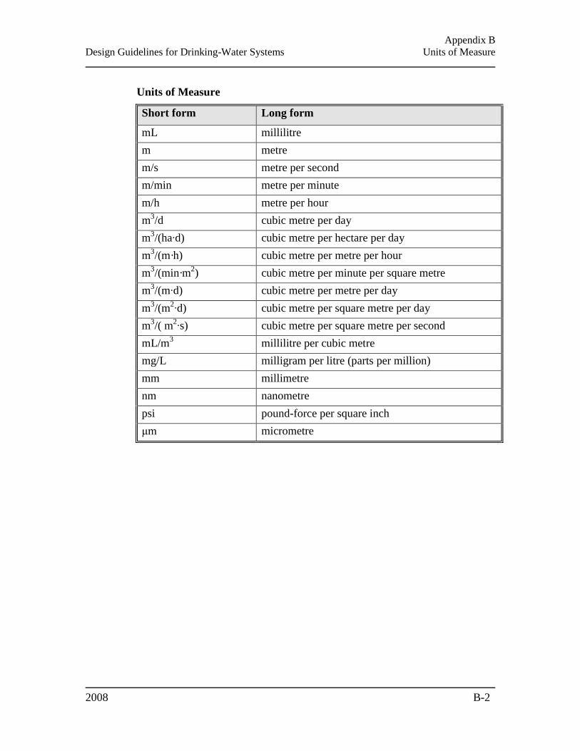
Appendix B
Design Guidelines for Drinking-Water Systems Units of Measure
2008 B-2
Units of Measure
Short form Long form
mL millilitre
m metre
m/s metre per second
m/min metre per minute
m/h metre per hour
m3/d cubic metre per day
m3/(ha∙d) cubic metre per hectare per day
m3/(m·h) cubic metre per metre per hour
m3/(min·m
2) cubic metre per minute per square metre
m3/(m∙d) cubic metre per metre per day
m3/(m
2∙d) cubic metre per square metre per day
m3/( m
2∙s) cubic metre per square metre per second
mL/m3 millilitre per cubic metre
mg/L milligram per litre (parts per million)
mm millimetre
nm nanometre
psi pound-force per square inch
μm micrometre
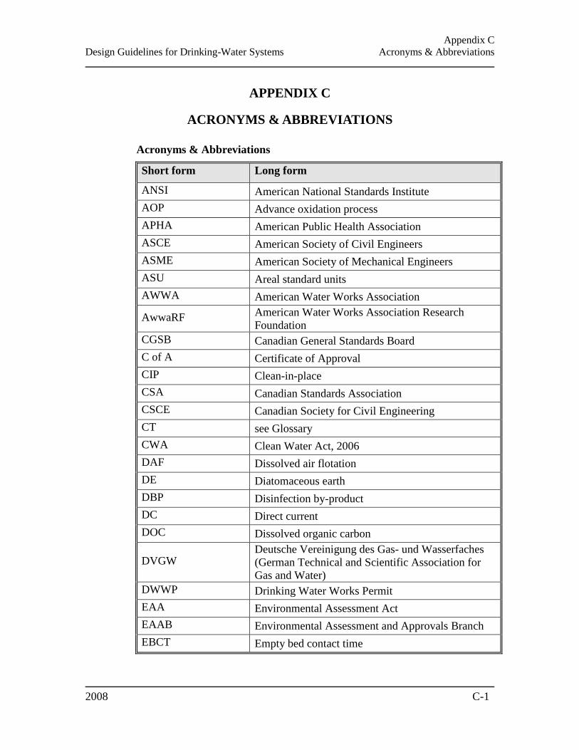
Appendix C
Design Guidelines for Drinking-Water Systems Acronyms & Abbreviations
2008 C-1
APPENDIX C
ACRONYMS & ABBREVIATIONS
Acronyms & Abbreviations
Short form Long form
ANSI American National Standards Institute
AOP Advance oxidation process
APHA American Public Health Association
ASCE American Society of Civil Engineers
ASME American Society of Mechanical Engineers
ASU Areal standard units
AWWA American Water Works Association
AwwaRF American Water Works Association Research
Foundation
CGSB Canadian General Standards Board
C of A Certificate of Approval
CIP Clean-in-place
CSA Canadian Standards Association
CSCE Canadian Society for Civil Engineering
CT see Glossary
CWA Clean Water Act, 2006
DAF Dissolved air flotation
DE Diatomaceous earth
DBP Disinfection by-product
DC Direct current
DOC Dissolved organic carbon
DVGW Deutsche Vereinigung des Gas- und Wasserfaches
(German Technical and Scientific Association for
Gas and Water)
DWWP Drinking Water Works Permit
EAA Environmental Assessment Act
EAAB Environmental Assessment and Approvals Branch
EBCT Empty bed contact time
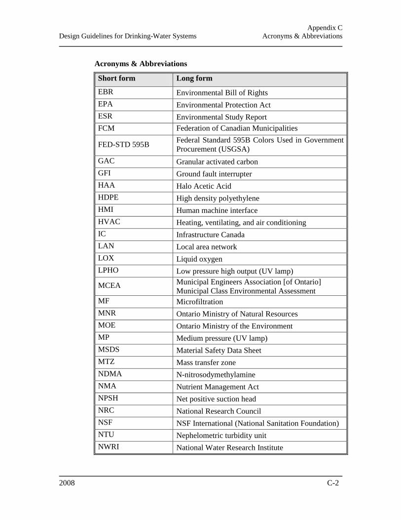
Appendix C
Design Guidelines for Drinking-Water Systems Acronyms & Abbreviations
2008 C-2
Acronyms & Abbreviations
Short form Long form
EBR Environmental Bill of Rights
EPA Environmental Protection Act
ESR Environmental Study Report
FCM Federation of Canadian Municipalities
FED-STD 595B Federal Standard 595B Colors Used in Government
Procurement (USGSA)
GAC Granular activated carbon
GFI Ground fault interrupter
HAA Halo Acetic Acid
HDPE High density polyethylene
HMI Human machine interface
HVAC Heating, ventilating, and air conditioning
IC Infrastructure Canada
LAN Local area network
LOX Liquid oxygen
LPHO Low pressure high output (UV lamp)
MCEA Municipal Engineers Association [of Ontario]
Municipal Class Environmental Assessment
MF Microfiltration
MNR Ontario Ministry of Natural Resources
MOE Ontario Ministry of the Environment
MP Medium pressure (UV lamp)
MSDS Material Safety Data Sheet
MTZ Mass transfer zone
NDMA N-nitrosodymethylamine
NMA Nutrient Management Act
NPSH Net positive suction head
NRC National Research Council
NSF NSF International (National Sanitation Foundation)
NTU Nephelometric turbidity unit
NWRI National Water Research Institute

Appendix C
Design Guidelines for Drinking-Water Systems Acronyms & Abbreviations
2008 C-3
Acronyms & Abbreviations
Short form Long form
ON ỒNorm Österreichisches Normungsinstitut (Austrian
Standards Institute)
OPS Ontario Provincial Standards for Roads and Public
Works
OPSS Ontario Provincial Standards Specification
OWRA Ontario Water Resources Act
P&ID Process and instrumentation diagrams
PAC Powdered activated carbon
PCN Process control network
PEO Professional Engineers of Ontario
PFD Process flow diagrams
PIT Pressure indicating transmitter
PRV Pressure regulating valve
PSA Pressure swing adsorption
PVC Polyvinyl Chloride
SDWA Safe Drinking Water Act
SOR Surface overflow rate
RTC Real-Time Control
TCU True colour units
TDH Total dynamic head
THM Trihalomethane
THMFP Trihalomethane formation potential
TOC Total organic carbon
TSSA Technical Standards and Safety Authority
TWL Top water level
T10 see Glossary
SCADA Supervisor control and data acquisition
SDS Simulated distribution system
UF Ultrafiltration
UNS Unified Numbering System for Metals and Alloys
UPS Uninterruptible power supply

Appendix C
Design Guidelines for Drinking-Water Systems Acronyms & Abbreviations
2008 C-4
Acronyms & Abbreviations
Short form Long form
USEPA United States Environmental Protection Agency
USGSA United States General Services Administration
UTM Universal Transverse Mercator
UV Ultraviolet light
UVT UV transmittance
VAC Volts of alternating current
VFD Variable frequency drive
VSA Vacuum swing adsorption
WEF Water Environment Federation
WTP Water treatment plant
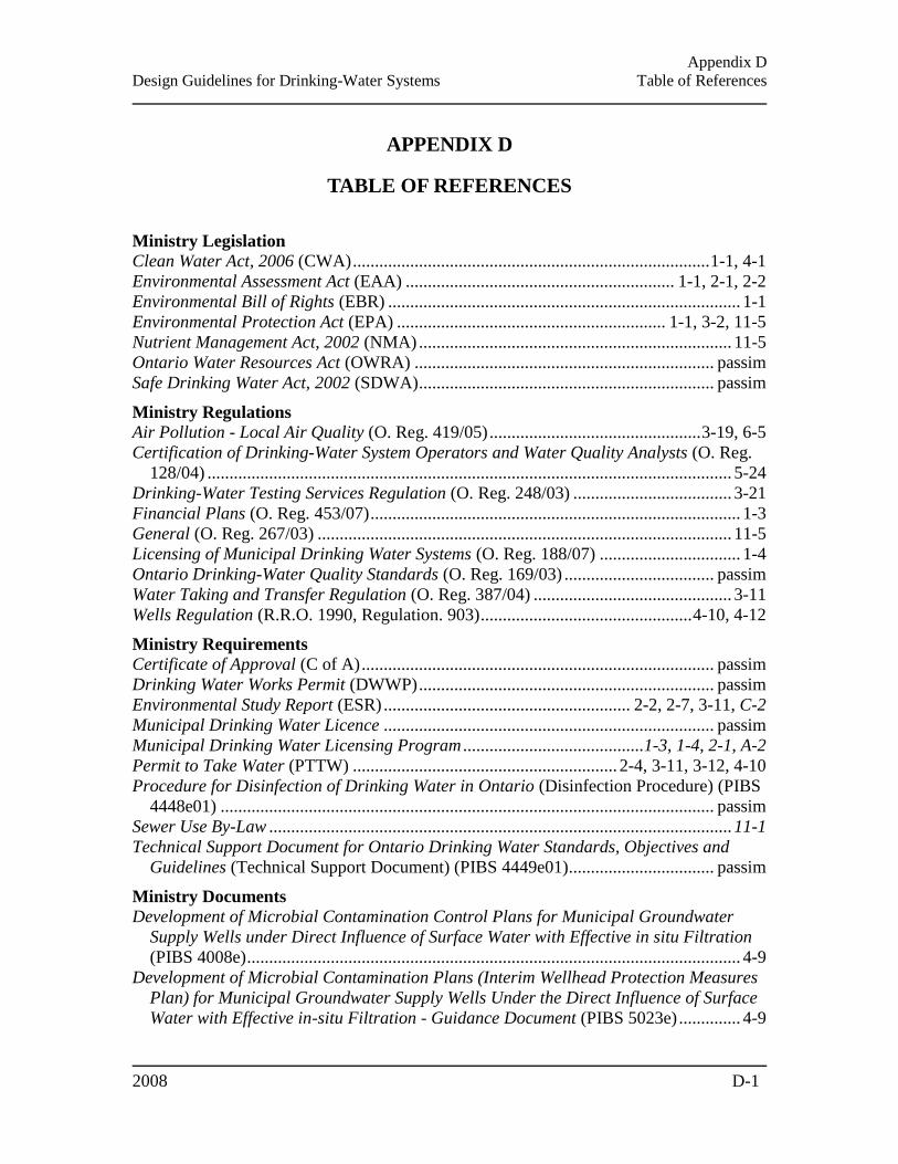
Appendix D
Design Guidelines for Drinking-Water Systems Table of References
2008 D-1
APPENDIX D
TABLE OF REFERENCES
Ministry Legislation Clean Water Act, 2006 (CWA) ................................................................................. 1-1, 4-1
Environmental Assessment Act (EAA) ............................................................. 1-1, 2-1, 2-2
Environmental Bill of Rights (EBR) ................................................................................ 1-1
Environmental Protection Act (EPA) ............................................................. 1-1, 3-2, 11-5
Nutrient Management Act, 2002 (NMA) ....................................................................... 11-5
Ontario Water Resources Act (OWRA) .................................................................... passim
Safe Drinking Water Act, 2002 (SDWA) ................................................................... passim
Ministry Regulations Air Pollution - Local Air Quality (O. Reg. 419/05) ................................................ 3-19, 6-5
Certification of Drinking-Water System Operators and Water Quality Analysts (O. Reg.
128/04) ....................................................................................................................... 5-24
Drinking-Water Testing Services Regulation (O. Reg. 248/03) .................................... 3-21
Financial Plans (O. Reg. 453/07) .................................................................................... 1-3
General (O. Reg. 267/03) .............................................................................................. 11-5
Licensing of Municipal Drinking Water Systems (O. Reg. 188/07) ................................ 1-4
Ontario Drinking-Water Quality Standards (O. Reg. 169/03) .................................. passim
Water Taking and Transfer Regulation (O. Reg. 387/04) ............................................. 3-11
Wells Regulation (R.R.O. 1990, Regulation. 903) ................................................ 4-10, 4-12
Ministry Requirements Certificate of Approval (C of A) ................................................................................ passim
Drinking Water Works Permit (DWWP) ................................................................... passim
Environmental Study Report (ESR) ........................................................ 2-2, 2-7, 3-11, C-2
Municipal Drinking Water Licence ........................................................................... passim
Municipal Drinking Water Licensing Program ......................................... 1-3, 1-4, 2-1, A-2
Permit to Take Water (PTTW) ............................................................ 2-4, 3-11, 3-12, 4-10
Procedure for Disinfection of Drinking Water in Ontario (Disinfection Procedure) (PIBS
4448e01) ................................................................................................................ passim
Sewer Use By-Law ......................................................................................................... 11-1
Technical Support Document for Ontario Drinking Water Standards, Objectives and
Guidelines (Technical Support Document) (PIBS 4449e01)................................. passim
Ministry Documents Development of Microbial Contamination Control Plans for Municipal Groundwater
Supply Wells under Direct Influence of Surface Water with Effective in situ Filtration
(PIBS 4008e) ................................................................................................................ 4-9
Development of Microbial Contamination Plans (Interim Wellhead Protection Measures
Plan) for Municipal Groundwater Supply Wells Under the Direct Influence of Surface
Water with Effective in-situ Filtration - Guidance Document (PIBS 5023e) .............. 4-9
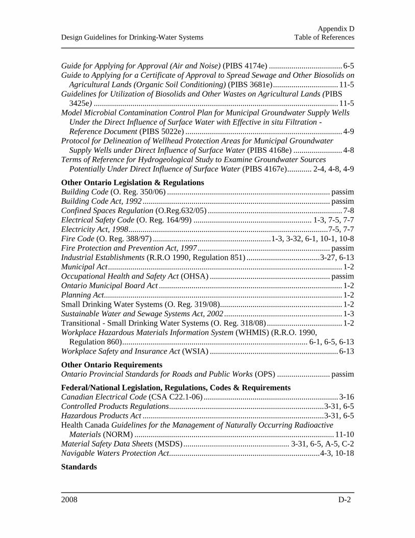
Appendix D
Design Guidelines for Drinking-Water Systems Table of References
2008 D-2
Guide for Applying for Approval (Air and Noise) (PIBS 4174e) .................................... 6-5
Guide to Applying for a Certificate of Approval to Spread Sewage and Other Biosolids on
Agricultural Lands (Organic Soil Conditioning) (PIBS 3681e) ................................ 11-5
Guidelines for Utilization of Biosolids and Other Wastes on Agricultural Lands (PIBS
3425e) ........................................................................................................................ 11-5
Model Microbial Contamination Control Plan for Municipal Groundwater Supply Wells
Under the Direct Influence of Surface Water with Effective in situ Filtration -
Reference Document (PIBS 5022e) ............................................................................. 4-9
Protocol for Delineation of Wellhead Protection Areas for Municipal Groundwater
Supply Wells under Direct Influence of Surface Water (PIBS 4168e) ........................ 4-8
Terms of Reference for Hydrogeological Study to Examine Groundwater Sources
Potentially Under Direct Influence of Surface Water (PIBS 4167e) ............ 2-4, 4-8, 4-9
Other Ontario Legislation & Regulations Building Code (O. Reg. 350/06) ................................................................................ passim
Building Code Act, 1992 ............................................................................................ passim
Confined Spaces Regulation (O.Reg.632/05) .................................................................. 7-8
Electrical Safety Code (O. Reg. 164/99) .......................................................... 1-3, 7-5, 7-7
Electricity Act, 1998.................................................................................................. 7-5, 7-7
Fire Code (O. Reg. 388/97) .......................................................... 1-3, 3-32, 6-1, 10-1, 10-8
Fire Protection and Prevention Act, 1997 ................................................................. passim
Industrial Establishments (R.R.O 1990, Regulation 851) .................................... 3-27, 6-13
Municipal Act ................................................................................................................... 1-2
Occupational Health and Safety Act (OHSA) ........................................................... passim
Ontario Municipal Board Act .......................................................................................... 1-2
Planning Act..................................................................................................................... 1-2
Small Drinking Water Systems (O. Reg. 319/08)............................................................ 1-2
Sustainable Water and Sewage Systems Act, 2002 .......................................................... 1-3
Transitional - Small Drinking Water Systems (O. Reg. 318/08) ..................................... 1-2
Workplace Hazardous Materials Information System (WHMIS) (R.R.O. 1990,
Regulation 860) ........................................................................................... 6-1, 6-5, 6-13
Workplace Safety and Insurance Act (WSIA) ............................................................... 6-13
Other Ontario Requirements Ontario Provincial Standards for Roads and Public Works (OPS) .......................... passim
Federal/National Legislation, Regulations, Codes & Requirements Canadian Electrical Code (CSA C22.1-06) .................................................................. 3-16
Controlled Products Regulations ............................................................................ 3-31, 6-5
Hazardous Products Act ......................................................................................... 3-31, 6-5
Health Canada Guidelines for the Management of Naturally Occurring Radioactive
Materials (NORM) .................................................................................................. 11-10
Material Safety Data Sheets (MSDS) .................................................... 3-31, 6-5, A-5, C-2
Navigable Waters Protection Act.......................................................................... 4-3, 10-18
Standards
Appendix D
Design Guidelines for Drinking-Water Systems Table of References
2008 D-3
ANSI/HI 9.8-1998 Pump Intake Design ........................................................................... 7-4
ANSI/HI Pump Standards ......................................................................................... 7-1, 7-4
APHA/AWWA/WEF Standard Methods for the Evaluation of Water and Wastewater .. 5-
35
AWWA Standard A100: Water Wells ........................................................................... 4-10
AWWA Standard B100: Filtering Material ................................................................... 5-17
AWWA Standard B101: Precoat Filter Media ............................................................. 5-51
AWWA Standard B102: Manganese Greensand for Filters ........................................ 5-51
AWWA Standard B302: Ammonium Sulfate ................................................................ 6-19
AWWA Standard B604: Granular Activated Carbon .................................................... 5-17
AWWA Standard C502: Dry-Barrel Fire Hydrants ..................................................... 10-8
AWWA Standard C510 Double Check Valve Backflow Prevention Assembly ............ 3-30
AWWA Standard C510: Double Check Valve Backflow Prevention Assembly ......... 10-19
AWWA Standard C511: Reduced-Pressure Principle Backflow Prevention Assembly ... 3-
30, 10-19
AWWA Standard C512: Air Release, Air/Vacuum, and Combination Air Valves for
Waterworks Service ................................................................................................. 10-11
AWWA Standard C650-series (Disinfection of Facilities) ........................................... 3-31
AWWA Standard C651-05: Disinfecting Water Mains .............................................. 10-13
AWWA Standard C652: Disinfection of Water-Storage Facilities .............................. 8-12
AWWA Standard C800: Underground Service Line Valves and Fittings .................. 10-12
AWWA Standard D104: Automatically Controlled, Impressed-Current Cathodic
Protection for the Interior of Steel Water Tanks ....................................................... 8-14
CAN/CGSB 24.3-92 Identification of Piping Systems ................................................... 3-27
CAN/CSA-B64 SERIES-01 Backflow Preventers and Vacuum Breakers . 3-30, 6-12, 10-19
CAN/CSA-B64.10-01/B64.10.1-01 Manual for the Selection and Installation of Backflow
Prevention Devices/Manual for the Maintenance and Field Testing of Backflow
Prevention Devices .................................................................... 3-30, 6-12, 10-19, 10-20
CAN/CSA-B64.10S1-04/B64.10.1S1-Supplement #1 to CAN/CSA-B64.10-01/CAN/CSA-
B64.10.1-01 ........................................................................................... 3-30, 6-13, 10-19
CGSB 1-GP-12c Standard Paint Colours, Part 1 Colour Identification and Selection 3-27
DVGW Technical Standard W 294 ............................................................................... 5-41
NSF/ANSI Standard 53: Drinking Water Treatment Units - Health Effects ................ 5-31
NSF/ANSI Standard 55: Ultraviolet Microbiological Water Treatment Systems ........ 5-41
NSF/ANSI Standard 60: Drinking Water Treatment Chemicals - Health Effects ........ 3-33
NSF/ANSI Standard 61: Drinking Water System Components - Health Effects ...... passim
ON ÖNORM M 5873 ..................................................................................................... 5-41
Ten-State Recommended Standards for Water Works .......................................... 5-43, 5-61
Guidance & Best Practice Documents ASCE/CSCE Cold Regions Utilities Monograph, 1996 ....................................... 12-1, 12-2
AWWA Emergency Power Source Planning for Water and Wastewater ....................... 7-7
AWWA Manual of Water Supply Practices M11 – Steel Water Pipe: A Guide for Design
and Installation .......................................................................................................... 10-4
Appendix D
Design Guidelines for Drinking-Water Systems Table of References
2008 D-4
AWWA Manual of Water Supply Practices M14 – Recommended Practice for Backflow
Prevention and Cross-Connection Control ................................. 3-28, 3-31, 6-13, 10-19
AWWA Manual of Water Supply Practices M20 – Water Chlorination/Chloramination
Practices and Principles ............................................................................................ 6-21
AWWA Manual of Water Supply Practices M22 – Sizing Water Service Lines and
Meters ...................................................................................................................... 10-12
AWWA Manual of Water Supply Practices M23 – PVC Pipe: Design and Installation 10-
4
AWWA Manual of Water Supply Practices M30 – Precoat Filtration ........................ 5-22
AWWA Manual of Water Supply Practices M31 – Distribution System Requirements for
Fire Protection ........................................................................................................... 10-2
AWWA Manual of Water Supply Practices M4 – Water Fluoridation Principles and
Practices .................................................................................................................... 6-28
AWWA Manual of Water Supply Practices M41 – Ductile-Iron Pipe Fittings ............ 10-4
AWWA Manual of Water Supply Practices M45 – Fibreglass Pipe Design ................ 10-4
AWWA Manual of Water Supply Practices M55 – PE Pipe - Design and Installation 10-4
AWWA Manual of Water Supply Practices M9 – Concrete Pressure Pipe ................. 10-4
AWWA Security Guidance for Water Utilities ............................................................... 8-8
AwwaRF Guidance Manual for Disposal of Chlorinated Water (Project #2513) ........ 6-21
AwwaRF Guidance Manual for Maintaining Water Quality in the Distribution System
(Project #357)............................................................................................................. 10-2
AwwaRF Maintaining Water Quality in Finished Water Storage Facilities (Project #254)
...................................................................................................................................... 8-9
AwwaRF Water Treatment Plant Residuals Engineering (Project #2934) ................... 11-2
FCM/NRC/IC InfraGuide: National Guide to Sustainable Infrastructure report Selection
of Technologies for the Rehabilitation or Replacement of Sections of a Distribution
System ...................................................................................................................... 10-14
Fire Underwriters Survey Water Supply for Public Fire Protection ............ 8-3, 10-1, 10-8
NWRI-AwwaRF Ultraviolet Disinfection Guidelines for Drinking Water and Water
Reuse .......................................................................................................................... 5-41
PEO Guideline – Engineering Services to Municipalities (1998) ................................... 2-1
USEPA Cross-Connection Control Manual ............................................. 3-28, 6-13, 10-19
USEPA Distribution System White Papers.................................................................... 10-2
USEPA Ultraviolet Disinfection Guidance Manual ............................................. 5-38, 5-41
Rules USEPA Lead and Copper Rule...................................................................................... 5-59
USEPA Long Term 1 Enhanced Surface Water Treatment Rule .................................... 4-3
USEPA Long Term 2 Enhanced Surface Water Treatment Rule ........................... 4-3, 5-38
Other Authorities American National Standards Institute (ANSI) ......................................................... passim
American Society of Civil Engineers (ASCE).............................................. 12-1, 12-2, C-1
American Society of Mechanical Engineers (ASME) ........................................... 7-14, C-1
American Water Works Association (AWWA) ........................................................ passim

Appendix D
Design Guidelines for Drinking-Water Systems Table of References
2008 D-5
American Water Works Association Research Foundation (AwwaRF) .................... passim
Austrian Standards Institute/ Österreichisches Normungsinstitut (ON) ................ 5-41, C-3
Canadian General Standards Board (CGSB) ................................................................. 3-27
Canadian Society for Civil Engineers (CSCE) ............................................. 12-1, 12-2, C-1
Canadian Standards Association (CSA) .................................................................... passim
CGI Insurance Business Services (CGI-IBS) ......................................................... 8-3, 10-1
Chlorine Institute .......................................................................................... 6-8, 6-14, 6-16
Conservation Authority [Ontario] .................................................................................... 7-2
Environment Canada ...................................................................................................... 12-1
Federation of Canadian Municipalities (FCM) ............................................................ 10-14
Fire Underwriters Survey [Canada] .............................................................. 8-3, 10-1, 10-8
German Technical and Scientific Association for Gas and Water/ Deutsche Vereinigung
des Gas und Wasserfaches (DVGW) ................................................................. 5-41, C-1
Great Lakes–Upper Mississippi River Board of State and Provincial Public Health and
Environmental Managers – Water Supply Committee (Ten States) ................. 5-43, 5-61
Health Canada .............................................................................................................. 11-10
Hydraulic Institute (HI)........................................................................................... 7-1, 7-18
Infrastructure Canada (IC) ........................................................................................... 10-14
Municipal Engineers Association (MEA) [Ontario] ............................................. i, 3-2, C-2
National Research Council of Canada (NRC) .......................................... 10-14, 12-2, 12-3
National Water Research Institute (NWRI) ........................................................... 5-41, C-2
Natural Resources Canada ............................................................................................. 12-3
North American Society for Trenchless Technologies (NASTT) ............................... 10-14
NSF International (NSF) [National Sanitation Foundation] ...................................... passim
Ontario Ministry of Agriculture, Food and Rural Affairs.............................................. 11-5
Ontario Ministry of Labour ........................................................................ 1-2, 5-8, 7-1, 7-8
Ontario Ministry of Transportation ............................................................... 3-15, 8-7, 10-6
Professional Engineers of Ontario (PEO) ................................................................ 2-1, C-3
Technical Standards and Safety Authority (TSSA) ............................................... 3-18, C-3
United States Environmental Protection Agency (USEPA) ...................................... passim


![Guidelines for Drinking-Water Quality [WHO]](https://static.fdocuments.us/doc/165x107/577d27e21a28ab4e1ea51dbf/guidelines-for-drinking-water-quality-who.jpg)