DESIGN GUIDELINES Division 23 - MECHANICAL
53
DESIGN GUIDELINES Division 23 - MECHANICAL Release 3.0 April 2017 Released by: Cleveland Clinic Facilities and Construction 9500 Euclid Ave. Cleveland OH 44195 All information within this Document is considered CONFIDENTIAL and PROPRIETARY. By receipt and use of this Document, the recipient agrees not to divulge any of the information herein and attached hereto to persons other than those within the recipients’ organization that have specific need to know for the purposes of reviewing and referencing this information. Recipient also agrees not to use this information in any manner detrimental to the interests of Cleveland Clinic.
Transcript of DESIGN GUIDELINES Division 23 - MECHANICAL
DESIGN GUIDELINES
Division 23 - MECHANICAL
Release 3.0 April 2017 Released by: Cleveland Clinic Facilities and Construction 9500 Euclid Ave. Cleveland OH 44195
All information within this Document is considered CONFIDENTIAL and PROPRIETARY. By receipt and use of this Document, the recipient agrees not to divulge any of the information herein and attached hereto to persons other than those within the recipients’ organization that have specific need to know for the purposes of reviewing and referencing this information. Recipient also agrees not to use this information in any manner detrimental to the interests of Cleveland Clinic.
Cleveland Clinic
Design Guidelines Copyright © 2017
By Cleveland Clinic
These Design Guidelines, or parts thereof, may not be reproduced in any form without the permission of Cleveland Clinic.
Cleveland Clinic
Cleveland Clinic Design Guidelines: Division 23 - Mechanical
The following pages contain guidelines for the design and construction of new and
renovated facilities at all domestic Cleveland Clinic locations. They shall be used by A/E
firms in the preparation of drawings and specifications for construction of facilities.
The general purpose of each Design Guideline is to provide minimal criteria for
construction materials and equipment at Cleveland Clinic facilities regarding Codes and
FM Global compliance, warranty, approved products, execution, and uniformity.
The Guidelines are not Contract Specifications, but are used to prepare more detailed,
project-specific specifications. The Guidelines are intended to be used to address system
design aspects of equipment that Cleveland Clinic desires to standardize among facilities,
and identify prohibited materials and construction practices.
The use of these Guidelines is mandatory for all design or maintenance projects. Deviations
are discouraged. If project conditions arise which require a deviation, it shall be thoroughly
documented by the user and submitted to Cleveland Clinic for review and approval using
the Design Standard Deviation Request Form.
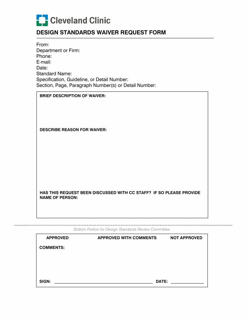
DESIGN STANDARDS WAIVER REQUEST FORM
From:
Department or Firm:
Phone:
E-mail:
Date:
Standard Name:
Specification, Guideline, or Detail Number:
Section, Page, Paragraph Number(s) or Detail Number:
BRIEF DESCRIPTION OF WAIVER:
DESCRIBE REASON FOR WAIVER:
HAS THIS REQUEST BEEN DISCUSSED WITH CC STAFF? IF SO PLEASE PROVIDE
NAME OF PERSON:
APPROVED APPROVED WITH COMMENTS NOT APPROVED
COMMENTS:
SIGN: DATE:
Bottom Portion for Design Standards Review Committee
DESIGN GUIDELINES: DIVISION 23 – MECHANICAL
1. Mechanical Drawing and Equipment Naming Requirements
2. General HVAC Design
3. HVAC Air Distribution
4. Diffuser and Grille
5. HVAC Hydronic Distribution
6. Steam and Condensate
7. Boiler Design
8. Heat Exchangers for HVAC
9. Chillers and Associated Equipment Design
10. HVAC Insulation and Labeling
11. Terminal Units
12. Facility Fuel Oil
13. Testing, Adjusting, and Balancing
** End of List **
Cleveland Clinic Design Standards Mechanical Systems Design Guidelines 1. Mechanical Drawing and Equipment Naming Requirements
April 2017 1 - 1
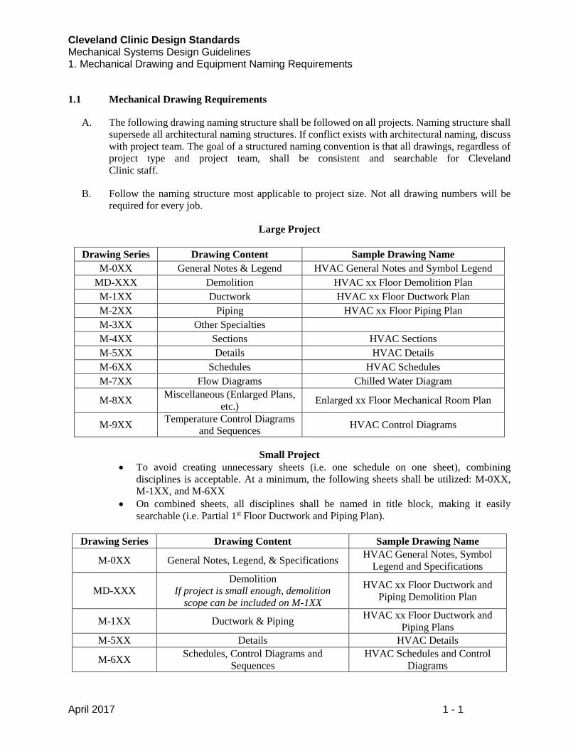
1.1 Mechanical Drawing Requirements
A. The following drawing naming structure shall be followed on all projects. Naming structure shall
supersede all architectural naming structures. If conflict exists with architectural naming, discuss
with project team. The goal of a structured naming convention is that all drawings, regardless of
project type and project team, shall be consistent and searchable for Cleveland
Clinic staff.
B. Follow the naming structure most applicable to project size. Not all drawing numbers will be
required for every job.
Large Project
Drawing Series Drawing Content Sample Drawing Name
M-0XX General Notes & Legend HVAC General Notes and Symbol Legend
MD-XXX Demolition HVAC xx Floor Demolition Plan
M-1XX Ductwork HVAC xx Floor Ductwork Plan
M-2XX Piping HVAC xx Floor Piping Plan
M-3XX Other Specialties
M-4XX Sections HVAC Sections
M-5XX Details HVAC Details
M-6XX Schedules HVAC Schedules
M-7XX Flow Diagrams Chilled Water Diagram
M-8XX Miscellaneous (Enlarged Plans,
etc.) Enlarged xx Floor Mechanical Room Plan
M-9XX Temperature Control Diagrams
and Sequences HVAC Control Diagrams
Small Project
To avoid creating unnecessary sheets (i.e. one schedule on one sheet), combining
disciplines is acceptable. At a minimum, the following sheets shall be utilized: M-0XX,
M-1XX, and M-6XX
On combined sheets, all disciplines shall be named in title block, making it easily
searchable (i.e. Partial 1st Floor Ductwork and Piping Plan).
Drawing Series Drawing Content Sample Drawing Name
M-0XX General Notes, Legend, & Specifications HVAC General Notes, Symbol
Legend and Specifications
MD-XXX
Demolition
If project is small enough, demolition
scope can be included on M-1XX
HVAC xx Floor Ductwork and
Piping Demolition Plan
M-1XX Ductwork & Piping HVAC xx Floor Ductwork and
Piping Plans
M-5XX Details HVAC Details
M-6XX Schedules, Control Diagrams and
Sequences
HVAC Schedules and Control
Diagrams
Cleveland Clinic Design Standards Mechanical Systems Design Guidelines 1. Mechanical Drawing and Equipment Naming Requirements
April 2017 1 - 2
C. Indicate all applicable codes followed on General Note Sheet (M-001).
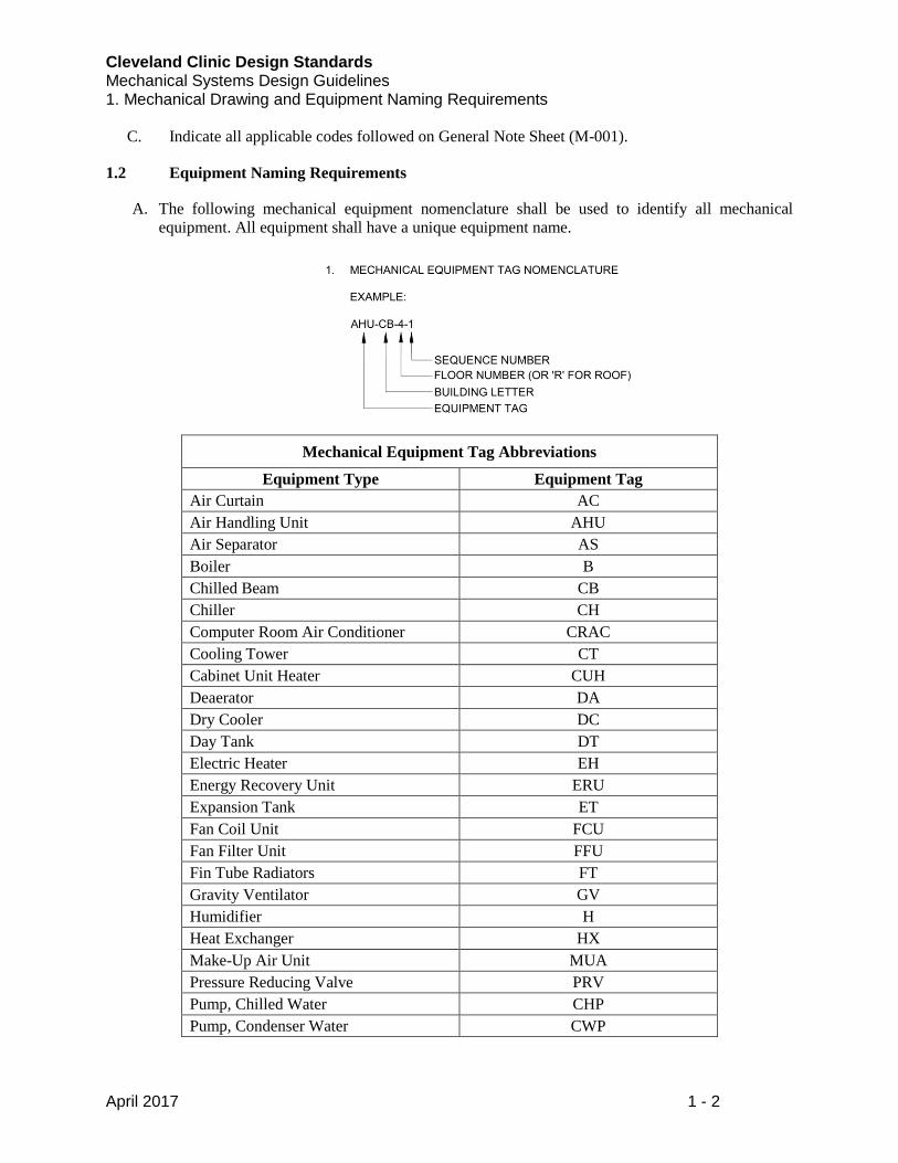
1.2 Equipment Naming Requirements
A. The following mechanical equipment nomenclature shall be used to identify all mechanical
equipment. All equipment shall have a unique equipment name.
Mechanical Equipment Tag Abbreviations
Equipment Type Equipment Tag
Air Curtain AC
Air Handling Unit AHU
Air Separator AS
Boiler B
Chilled Beam CB
Chiller CH
Computer Room Air Conditioner CRAC
Cooling Tower CT
Cabinet Unit Heater CUH
Deaerator DA
Dry Cooler DC
Day Tank DT
Electric Heater EH
Energy Recovery Unit ERU
Expansion Tank ET
Fan Coil Unit FCU
Fan Filter Unit FFU
Fin Tube Radiators FT
Gravity Ventilator GV
Humidifier H
Heat Exchanger HX
Make-Up Air Unit MUA
Pressure Reducing Valve PRV
Pump, Chilled Water CHP
Pump, Condenser Water CWP
Cleveland Clinic Design Standards Mechanical Systems Design Guidelines 1. Mechanical Drawing and Equipment Naming Requirements
April 2017 1 - 3
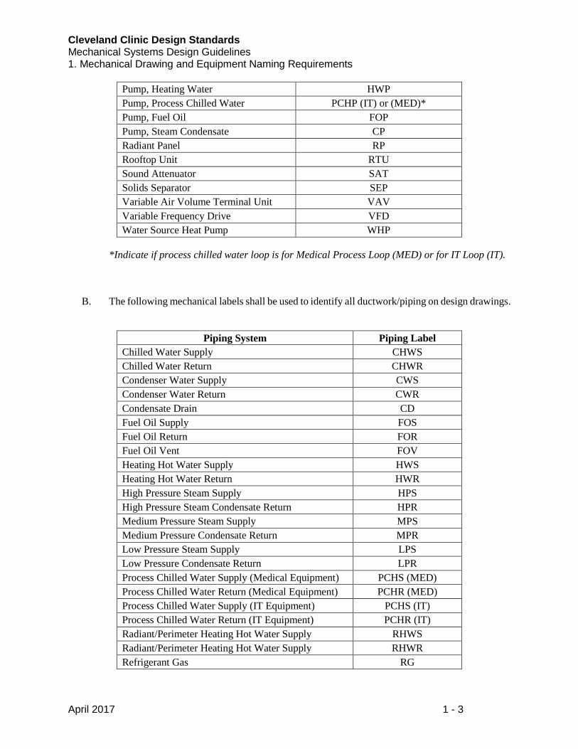
Pump, Heating Water HWP
Pump, Process Chilled Water PCHP (IT) or (MED)*
Pump, Fuel Oil FOP
Pump, Steam Condensate CP
Radiant Panel RP
Rooftop Unit RTU
Sound Attenuator SAT
Solids Separator SEP
Variable Air Volume Terminal Unit VAV
Variable Frequency Drive VFD
Water Source Heat Pump WHP
*Indicate if process chilled water loop is for Medical Process Loop (MED) or for IT Loop (IT).
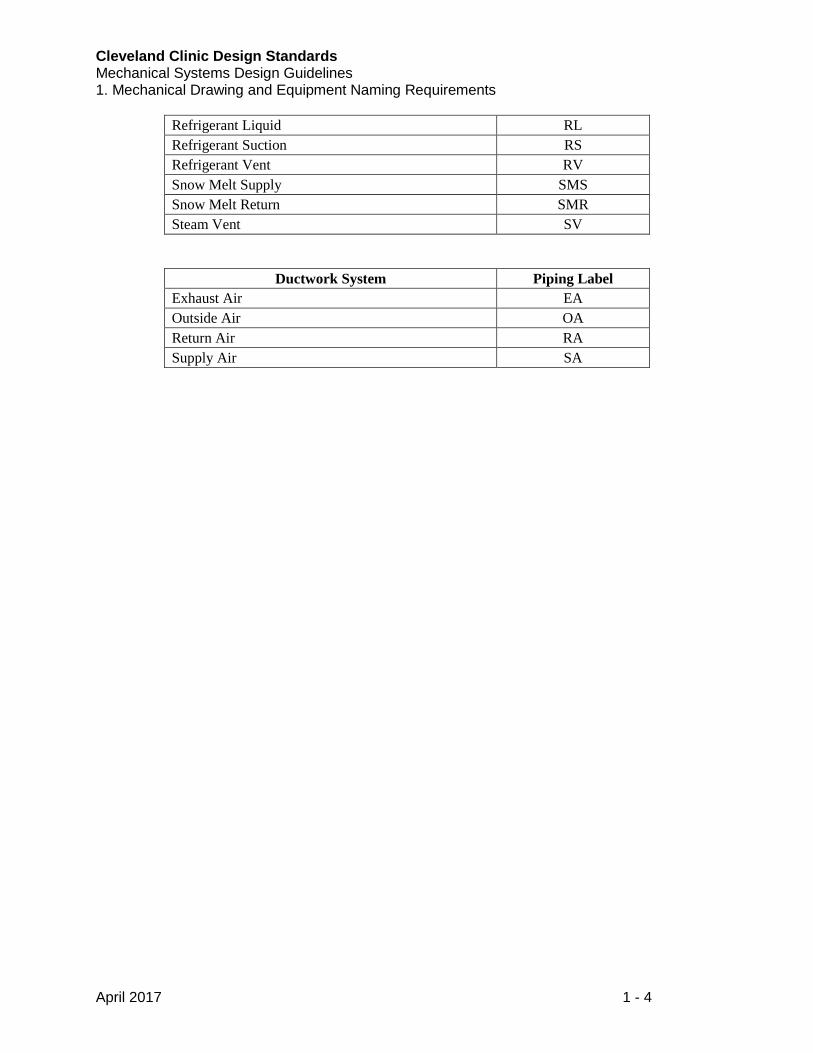
B. The following mechanical labels shall be used to identify all ductwork/piping on design drawings.
Piping System Piping Label
Chilled Water Supply CHWS
Chilled Water Return CHWR
Condenser Water Supply CWS
Condenser Water Return CWR
Condensate Drain CD
Fuel Oil Supply FOS
Fuel Oil Return FOR
Fuel Oil Vent FOV
Heating Hot Water Supply HWS
Heating Hot Water Return HWR
High Pressure Steam Supply HPS
High Pressure Steam Condensate Return HPR
Medium Pressure Steam Supply MPS
Medium Pressure Condensate Return MPR
Low Pressure Steam Supply LPS
Low Pressure Condensate Return LPR
Process Chilled Water Supply (Medical Equipment) PCHS (MED)
Process Chilled Water Return (Medical Equipment) PCHR (MED)
Process Chilled Water Supply (IT Equipment) PCHS (IT)
Process Chilled Water Return (IT Equipment) PCHR (IT)
Radiant/Perimeter Heating Hot Water Supply RHWS
Radiant/Perimeter Heating Hot Water Supply RHWR
Refrigerant Gas RG
Cleveland Clinic Design Standards Mechanical Systems Design Guidelines 1. Mechanical Drawing and Equipment Naming Requirements
April 2017 1 - 4
Refrigerant Liquid RL
Refrigerant Suction RS
Refrigerant Vent RV
Snow Melt Supply SMS
Snow Melt Return SMR
Steam Vent SV
Ductwork System Piping Label
Exhaust Air EA
Outside Air OA
Return Air RA
Supply Air SA
Cleveland Clinic Design Standards MECHANICAL SYSTEMS DESIGN GUIDELINES 2. GENERAL HVAC DESIGN GUIDELINES
NOVEMBER 2016 2 - 1
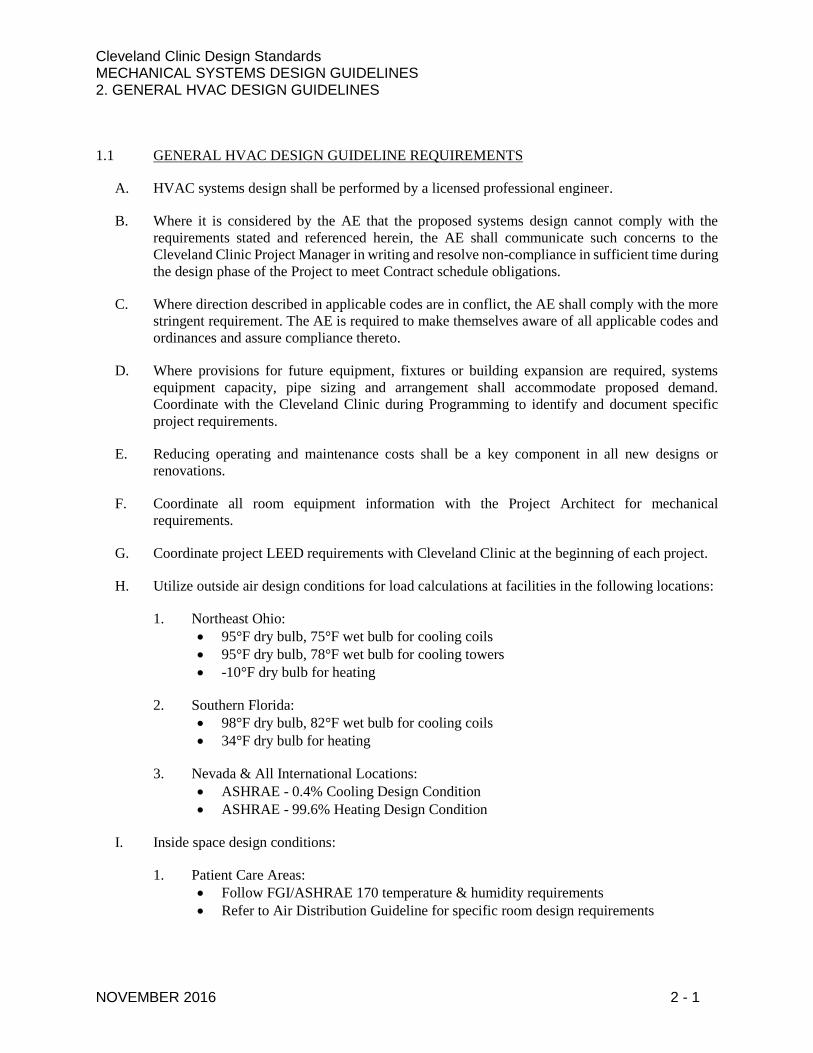
1.1 GENERAL HVAC DESIGN GUIDELINE REQUIREMENTS
A. HVAC systems design shall be performed by a licensed professional engineer.
B. Where it is considered by the AE that the proposed systems design cannot comply with the
requirements stated and referenced herein, the AE shall communicate such concerns to the
Cleveland Clinic Project Manager in writing and resolve non-compliance in sufficient time during
the design phase of the Project to meet Contract schedule obligations.
C. Where direction described in applicable codes are in conflict, the AE shall comply with the more
stringent requirement. The AE is required to make themselves aware of all applicable codes and
ordinances and assure compliance thereto.
D. Where provisions for future equipment, fixtures or building expansion are required, systems
equipment capacity, pipe sizing and arrangement shall accommodate proposed demand.
Coordinate with the Cleveland Clinic during Programming to identify and document specific
project requirements.
E. Reducing operating and maintenance costs shall be a key component in all new designs or
renovations.
F. Coordinate all room equipment information with the Project Architect for mechanical
requirements.
G. Coordinate project LEED requirements with Cleveland Clinic at the beginning of each project.
H. Utilize outside air design conditions for load calculations at facilities in the following locations:
1. Northeast Ohio:
95°F dry bulb, 75°F wet bulb for cooling coils
95°F dry bulb, 78°F wet bulb for cooling towers
-10°F dry bulb for heating
2. Southern Florida:
98°F dry bulb, 82°F wet bulb for cooling coils
34°F dry bulb for heating
3. Nevada & All International Locations:
ASHRAE - 0.4% Cooling Design Condition
ASHRAE - 99.6% Heating Design Condition
I. Inside space design conditions:
1. Patient Care Areas:
Follow FGI/ASHRAE 170 temperature & humidity requirements
Refer to Air Distribution Guideline for specific room design requirements
Cleveland Clinic Design Standards MECHANICAL SYSTEMS DESIGN GUIDELINES 2. GENERAL HVAC DESIGN GUIDELINES
NOVEMBER 2016 2 - 2
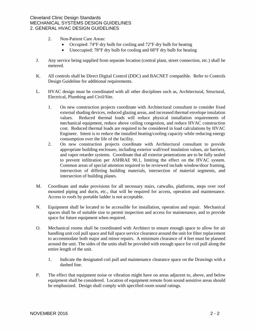
2. Non-Patient Care Areas:
Occupied: 74°F dry bulb for cooling and 72°F dry bulb for heating
Unoccupied: 78°F dry bulb for cooling and 68°F dry bulb for heating
J. Any service being supplied from separate location (central plant, street connection, etc.) shall be
metered.
K. All controls shall be Direct Digital Control (DDC) and BACNET compatible. Refer to Controls
Design Guideline for additional requirements.
L. HVAC design must be coordinated with all other disciplines such as, Architectural, Structural,
Electrical, Plumbing and Civil/Site.
1. On new construction projects coordinate with Architectural consultant to consider fixed
external shading devices, reduced glazing areas, and increased thermal envelope insulation
values. Reduced thermal loads will reduce physical installation requirements of
mechanical equipment, reduce above ceiling congestion, and reduce HVAC construction
cost. Reduced thermal loads are required to be considered in load calculations by HVAC
Engineer. Intent is to reduce the installed heating/cooling capacity while reducing energy
consumption over the life of the facility.
2. On new construction projects coordinate with Architectural consultant to provide
appropriate building enclosure, including exterior wall/roof insulation values, air barriers,
and vapor retarder systems. Coordinate that all exterior penetrations are to be fully sealed
to prevent infiltration per ASHRAE 90.1, limiting the effect on the HVAC system.
Common areas of special attention required to be reviewed include window/door framing,
intersection of differing building materials, intersection of material segments, and
intersection of building planes.
M. Coordinate and make provisions for all necessary stairs, catwalks, platforms, steps over roof
mounted piping and ducts, etc., that will be required for access, operation and maintenance.
Access to roofs by portable ladder is not acceptable.
N. Equipment shall be located to be accessible for installation, operation and repair. Mechanical
spaces shall be of suitable size to permit inspection and access for maintenance, and to provide
space for future equipment when required.
O. Mechanical rooms shall be coordinated with Architect to ensure enough space to allow for air
handling unit coil pull space and full space service clearance around the unit for filter replacement
to accommodate both major and minor repairs. A minimum clearance of 4 feet must be planned
around the unit. The sides of the units shall be provided with enough space for coil pull along the
entire length of the unit.
1. Indicate the designated coil pull and maintenance clearance space on the Drawings with a
dashed line.
P. The effect that equipment noise or vibration might have on areas adjacent to, above, and below
equipment shall be considered. Location of equipment remote from sound sensitive areas should
be emphasized. Design shall comply with specified room sound ratings.
Cleveland Clinic Design Standards MECHANICAL SYSTEMS DESIGN GUIDELINES 2. GENERAL HVAC DESIGN GUIDELINES
NOVEMBER 2016 2 - 3
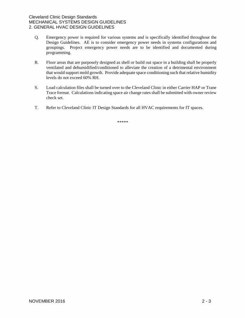
Q. Emergency power is required for various systems and is specifically identified throughout the
Design Guidelines. AE is to consider emergency power needs in systems configurations and
groupings. Project emergency power needs are to be identified and documented during
programming.
R. Floor areas that are purposely designed as shell or build out space in a building shall be properly
ventilated and dehumidified/conditioned to alleviate the creation of a detrimental environment
that would support mold growth. Provide adequate space conditioning such that relative humidity
levels do not exceed 60% RH.
S. Load calculation files shall be turned over to the Cleveland Clinic in either Carrier HAP or Trane
Trace format. Calculations indicating space air change rates shall be submitted with owner review
check set.
T. Refer to Cleveland Clinic IT Design Standards for all HVAC requirements for IT spaces.
*****
Cleveland Clinic Design Standards Mechanical Systems Design Guidelines 3. HVAC Air Distribution
April 2017 3 - 1
1.1 HVAC Air Distribution Requirements
A. Air handling unit (AHU) selection and performance shall comply with the code referenced and
Joint Commission/CMS referenced version of the following:
1. FGI Guidelines
2. ASHRAE Standard 170
3. ASHRAE Standard 62.1
4. ASHRAE Standard 90.1
B. Refer to Mechanical Systems Design Guidelines Section 2 – General HVAC for specific outdoor
and indoor design temperature and humidity requirements.
C. Buildings shall maintain a positive pressurization (5-15% net positive). Tighter buildings are
eligible for less net pressurization. Please note that if a building is connected to an adjacent
building via skyway or tunnel, the pressure relationship between the buildings shall be reviewed
and discussed with CC Engineer during design.
D. General AHU/RTU Fan Design
1. Variable frequency drives (VFD) shall be utilized in all air handling units and rooftop units.
Building type (e.g., hospital, outpatient facility, etc.) will determine level of redundancy
required for VFDs. Refer to building type requirements in this section. VFDs shall include
either a bypass switch or be configured in a manner that failure of one VFD does not
disable the entire unit. Fan motor shall be high efficiency.
2. Fans shall be selected so that they are capable of meeting the design CFM at a max 60 Hz
during normal operation. During emergency operation, 60 Hz can be exceeded.
3. The maximum shaft speed on any fan shall be 2000 rpm.
4. Normal operation shall be no greater than 80% of the max wheel rpm.
5. Fan arrays are preferred for use on air handling units and energy recovery units (ERUs).
6. Air handling unit fans shall have an efficiency rating where the ratio of the fan system
power to the supply fan airflow rate (main fan) of each HVAC system at design conditions
shall not exceed the allowable fan system power indicated in the latest ASHRAE Standard
90.1.
7. Variable-pitch and variable-inlet fans are not acceptable.
E. AHU/RTU Coil Design
1. Each cooling coil shall not exceed eight (8) rows and ten (10) fins per inch (FPI).
a. Design two (2) coils in a series arrangement if the cooling coil capacity requirement
exceeds the capability of an 8 row, 10 FPI coil. Chilled water shall be piped in series
through both coils, and a 42 inch access section shall be provided between the two
equally sized coils. Chilled water velocity through the coil tubes should be 8 fps
maximum. (The minimum ARI Standard 410 rating condition for water velocity
through a coil is 1 fps).
Cleveland Clinic Design Standards Mechanical Systems Design Guidelines 3. HVAC Air Distribution
April 2017 3 - 2
2. Maximum cooling coil discharge face velocity shall not exceed 450 fpm. Heating coil
discharge face velocity shall not exceed 800 fpm.
3. Coil connections 2 ½ inches and larger must include bolted flange spools and be arranged
to allow the coils to be pulled and installed without having to remove the control valves.
Two-inch and smaller connections may be union connections. Provide strainers on inlet of
the coils. Provide a pressure and temperature gauge downstream of the cooling coil control
valve.
4. Control valve to be on discharge side of coil.
5. Ultra violet (UV) lamps shall be located on the leaving air side of the cooling coil.
F. Access doors (or panels) on the air handling unit sections shall always open against the positive
side of the door and shall not be blocked by internal filter casings or internal equipment
components. Micro switches or safety switch interlocks need to be provided at access doors or
panels on UV sections to protect maintenance personnel from possible injuries. Windows shall
be located 5 feet above finished floor.
G. Coordinate location of wall-mounted room temperature sensors with furniture and equipment, so
that sensor locations do not conflict with tall items of furniture/equipment.
H. Electronic filters are not acceptable.
I. Fan belt self-tension adjusters are not acceptable.
J. Variable Air Volume (VAV) boxes shall be located outside of patient occupied spaces for ease
of maintenance.
K. Ductwork Design
1. Low Pressure Ductwork
a. Ductwork subjected to velocities of 1600 fpm or less and operating pressure of 2
inches w.g. or less, positive or negative.
b. Required at following locations:
1) Supply air systems downstream of terminal units and fan coil units
2) Return air systems
3) Outside air intake plenums
c. Volume dampers shall be provided at all individual, low-pressure take-offs. Low
pressure take-offs shall be bellmouth or 45 degree boot tap.
d. Low pressure ductwork may be utilized in lieu of medium pressure ductwork for
energy conservation and sustainability.
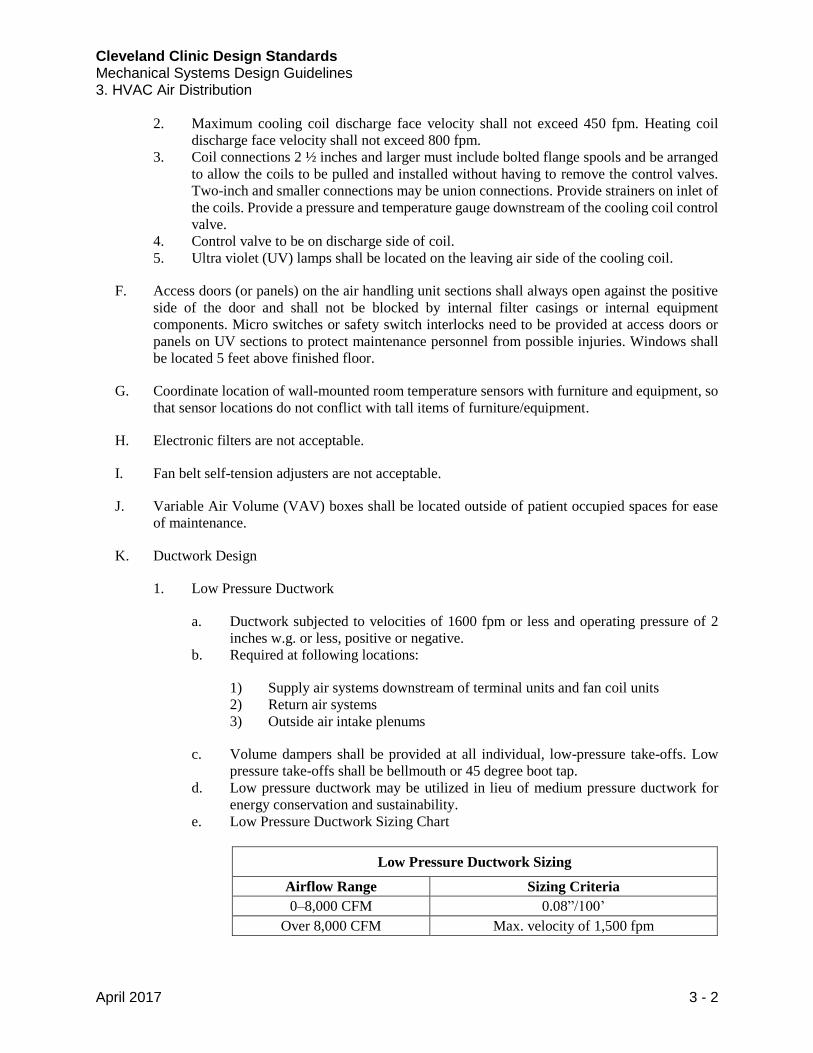
e. Low Pressure Ductwork Sizing Chart
Low Pressure Ductwork Sizing
Airflow Range Sizing Criteria
0–8,000 CFM 0.08”/100’
Over 8,000 CFM Max. velocity of 1,500 fpm
Cleveland Clinic Design Standards Mechanical Systems Design Guidelines 3. HVAC Air Distribution
April 2017 3 - 3
2. Medium and High Pressure Ductwork
a. Ductwork subject to operating pressures in excess of 2 inches w.g., positive or
negative, and up to 6 inches w.g., positive or negative.
b. Required at following locations:
1) Air conditioning supply air systems from air handling unit discharge to
terminal units
2) Exhaust air systems
3) Relief air systems
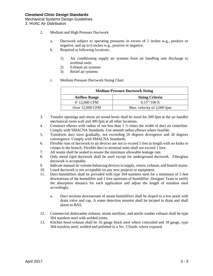
c. Medium Pressure Ductwork Sizing Chart
Medium Pressure Ductwork Sizing
Airflow Range Sizing Criteria
0–12,000 CFM 0.15”/100 ft
Over 12,000 CFM Max. velocity of 2,000 fpm
3. Transfer openings and return air sound boots shall be sized for 500 fpm at the air handler
mechanical room wall and 300 fpm at all other locations.
4. Construct elbows with radius of not less than 1 ½ times the width of duct on centerline.
Comply with SMACNA Standards. Use smooth radius elbows where feasible.
5. Transform duct sizes gradually, not exceeding 20 degrees divergence and 30 degrees
convergence. Comply with SMACNA Standards.
6. Flexible runs of ductwork to air devices are not to exceed 5 feet in length with no kinks or
crimps in the branch. Flexible duct to terminal units shall not exceed 1 foot.
7. All seams shall be sealed to ensure the minimum allowable leakage rate.
8. Only metal rigid ductwork shall be used except for underground ductwork. Fiberglass
ductwork is acceptable.
9. Indicate manual air volume balancing devices in supply, return, exhaust, and branch mains.
10. Lined ductwork is not acceptable on any new projects or equipment.
11. Duct humidifiers shall be provided with type 304 stainless steel for a minimum of 5 feet
downstream of the humidifier and 1 foot upstream of humidifier. Designer Team to verify
the absorption distance for each application and adjust the length of stainless steel
accordingly.
a. Duct sections downstream of steam humidifiers shall be sloped to a low point with
drain valve and cap. A water detection monitor shall be located in drain and shall
alarm to BAS.
12. Commercial dishwasher exhaust, steam sterilizer, and sterile washer exhaust shall be type
304 stainless steel with welded joints.
13. Kitchen hood exhaust shall be 16 gauge black steel where concealed and 18 gauge, type
304 stainless steel, welded and polished to a No. 3 finish, where exposed.
Cleveland Clinic Design Standards Mechanical Systems Design Guidelines 3. HVAC Air Distribution
April 2017 3 - 4
L. Fire & Smoke Dampers
1. Where a horizontal fire damper is required, it shall be blade type. Shutter type fire dampers
shall not be used in the horizontal position.
M. Exhaust and Intake Louvers
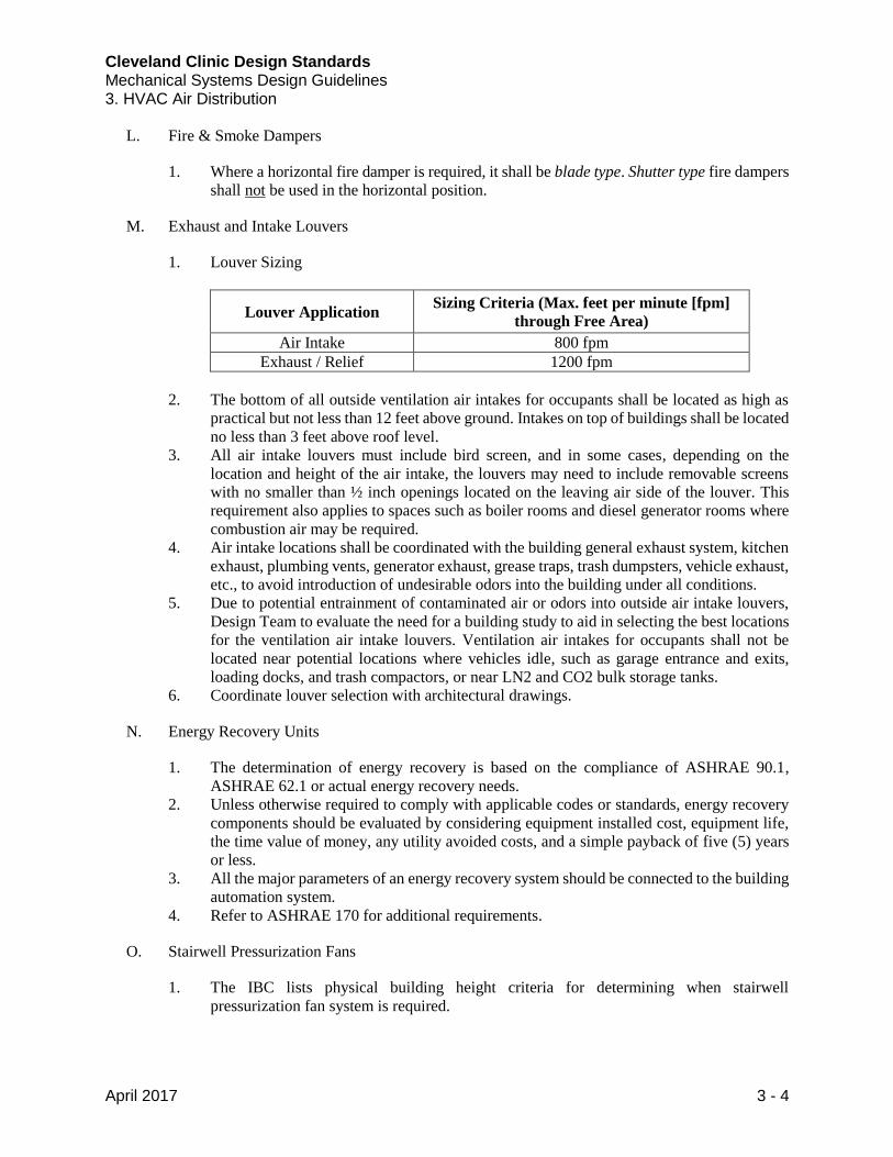
1. Louver Sizing
Louver Application Sizing Criteria (Max. feet per minute [fpm]
through Free Area)
Air Intake 800 fpm
Exhaust / Relief 1200 fpm
2. The bottom of all outside ventilation air intakes for occupants shall be located as high as
practical but not less than 12 feet above ground. Intakes on top of buildings shall be located
no less than 3 feet above roof level.
3. All air intake louvers must include bird screen, and in some cases, depending on the
location and height of the air intake, the louvers may need to include removable screens
with no smaller than ½ inch openings located on the leaving air side of the louver. This
requirement also applies to spaces such as boiler rooms and diesel generator rooms where
combustion air may be required.
4. Air intake locations shall be coordinated with the building general exhaust system, kitchen
exhaust, plumbing vents, generator exhaust, grease traps, trash dumpsters, vehicle exhaust,
etc., to avoid introduction of undesirable odors into the building under all conditions.
5. Due to potential entrainment of contaminated air or odors into outside air intake louvers,
Design Team to evaluate the need for a building study to aid in selecting the best locations
for the ventilation air intake louvers. Ventilation air intakes for occupants shall not be
located near potential locations where vehicles idle, such as garage entrance and exits,
loading docks, and trash compactors, or near LN2 and CO2 bulk storage tanks.
6. Coordinate louver selection with architectural drawings.
N. Energy Recovery Units
1. The determination of energy recovery is based on the compliance of ASHRAE 90.1,
ASHRAE 62.1 or actual energy recovery needs.
2. Unless otherwise required to comply with applicable codes or standards, energy recovery
components should be evaluated by considering equipment installed cost, equipment life,
the time value of money, any utility avoided costs, and a simple payback of five (5) years
or less.
3. All the major parameters of an energy recovery system should be connected to the building
automation system.
4. Refer to ASHRAE 170 for additional requirements.
O. Stairwell Pressurization Fans
1. The IBC lists physical building height criteria for determining when stairwell
pressurization fan system is required.
Cleveland Clinic Design Standards Mechanical Systems Design Guidelines 3. HVAC Air Distribution
April 2017 3 - 5
2. The stairwell pressurization system shall meet or exceed latest edition of NFPA
requirements.
3. Buildings over seven (7) stories should be evaluated for two (2) fans for pressurization of
each building exit stairwell. One fan shall be located at the top of the stairwell and the other
fan shall be located near the bottom of the stairwell.
4. The fan shall be variable volume using a VFD and shall maintain positive static pressure
in each stairwell. The differential pressure across the stairwell access door shall not exceed
the maximum opening force as specified in the latest edition of NFPA 92A.
P. Vestibules
1. All vestibules shall be positively pressurized with supply air from central air system. Where
feasible, provide a dedicated VAV box for vestibule.
2. Provide an air curtain at all exterior vestibule entrances. Provide steam or hot water air
curtains when available.
3. In cold weather climates, provide adequate heat to account for all wall loss and “pick-up”
load due to continual air changes.
1.2 Hospital HVAC Air Distribution Requirements
A. Baseline design for a hospital shall be a VAV system with heating hot water reheat coils. System
shall be reviewed with CC Engineer during project design.
1. One (1) patient room shall be served from one (1) VAV box. Review zoning with CC
Engineer during project design.
B. Heating and cooling systems shall include 20% extra capacity for future renovations.
C. Air handling units that are roof mounted shall be located on a structural steel platform or curb
mounted with ease of maintenance designed into the unit.
D. Patient Treatment Air Handling Units
1. Air handling systems shall be designed as single duct variable air volume (VAV)
distribution systems with supply and return ducts.
2. Air handling units serving critical care areas shall have a fan array system where if one fan
fails, the remaining fans speed up to cover a minimum of 100% of the supply airflow and
80% of return airflow. Each fan shall have a dedicated VFD.
3. VAV terminals with reheat shall provide the required air change rates and maintain critical
pressure differentials with respect to adjoining spaces.
4. Where potential exists for diesel fumes/other odors (helipads, loading dock, etc.) to enter
air intake, air handlers shall be designed to accommodate the pressure drop from 12 inch
charcoal filters.
5. Coil drain pans shall be 316 stainless steel. Coils shall be mounted at a height so that
discharge of drain pan is located 12 inches minimum above finished floor. Drain pans shall
be individually piped and trapped with a discharge of ¾ inch minimum union connection.
Cascading of drain pans is acceptable.
6. A cost benefit analysis should be performed to determine if a mixed air temperature air
handling unit should be selected for 100% OA.
Cleveland Clinic Design Standards Mechanical Systems Design Guidelines 3. HVAC Air Distribution
April 2017 3 - 6
7. Each VAV air handler may include, but is not limited to, the following components for air
distribution systems:
a. Inlet section
b. Return fan, centrifugal type. (Fan type may change due to fan array; review change
with CC Engineer.) Fan(s) speed controlled by a VFD.
c. Economizer section with air blender
d. Pre-filter section MERV 7 (30%) as rated by ASHRAE Standard 52
e. Energy recovery pre-heat coil
f. Access section
g. Steam or hot water preheat coil; copper tubes; aluminum fins; maximum 10 FPI;
integral face and bypass. Pre-heat coil discharge temperature sensor.
h. Access section
i. Supply fan, centrifugal type. (Fan type may change due to fan array, review change
with Cleveland Clinic.) Fan(s) speed controlled by a VFD.
j. Chilled water cooling coil; copper tubes; aluminum fins; maximum 8 rows,
maximum 10 fins per inch; desaturation coil (blow thru units only). Provide with
flow taps. Provide freezestat on entering face of cooling coil. Provide manual
freezestat reset button adjacent to cooling coil access door.
k. Ultra violet (UV) lamps shall be located on the leaving air side of the cooling coil.
Access section with micro switches on door to disable unit.
l. Access section
m. Mist eliminator (blow thru units only)
n. Access section
o. Final filter selection shall comply with ASHRAE Standard 170.
1) Units serving operating rooms shall have HEPA filters.
p. Access section
q. Steam humidifier should be located after the final filters or at a distant sufficient to
be 100% evaporated prior to reaching the filter.
r. Discharge section
s. High static pressure and smoke detection shutdown control and reset capability.
High static pressure reset shall be push button type with LED indicator light. Locate
in a usable location.
t. Instrument measurement taps for static pressure, temperature, etc.
E. Airborne Infection Isolation (AII) Rooms
1. Refer to Cleveland Clinic Negative Isolation Room Standard.
2. Rooms must be designed as once-through ventilation systems served with dedicated
redundant (N+1) exhaust air fan systems. The quantity of supply air to each isolation room
shall meet the required supply and exhaust air offset to maintain the room at a 0.01”
negative pressure per Cleveland Clinic Negative Isolation Room Standard and also to meet
room total cooling and heating load requirements. The supply air VAV box shall modulate
to maintain negative pressure in the isolation room. Provide differential pressure monitor
with alarm points to BAS. The exhaust airflow rate from the isolation room shall meet the
minimum required air change rate and modulate to maintain constant CFM offset exhaust
airflow during all modes of system operation. The patient private restroom shall also be
Cleveland Clinic Design Standards Mechanical Systems Design Guidelines 3. HVAC Air Distribution
April 2017 3 - 7
considered as part of the isolation room exhaust air requirement. The exhaust shall have a
VAV box.
3. For each project, the total exhaust from all of the combined isolation rooms should be
filtered with a bag-in and bag-out HEPA filter housing prior to being discharged to the
environment by an exhaust fan with a discharge 10 feet minimum above roof level.
4. VFD control of fans to maintain duct static pressure as filters load up.
F. Patient Protective Environment (PE) Rooms
1. Rooms must be designed at proper outside ventilation and recirculation air change rates,
and maintained at the required minimum positive pressure with respect to the corridor and
adjacent rooms. Filter the supply air to PE rooms using MERV 17 HEPA filter ceiling
modules. Provide differential pressure monitor with alarm points to BAS.
2. The quantity of supply air to each PE room shall meet the required supply offset to maintain
the room at a positive pressure with respect to adjacent spaces and the corridor and to meet
the room’s cooling and heating load requirements. The supply air VAV box and the return
air VAV box shall modulate to maintain positive pressure in the space to 0.01” positive.
3. The exhaust airflow rate from the patient restroom shall be constant volume and included
as part of the required air change rate.
G. General Operating Room (OR) Suites (including Orthopedic)
1. OR suites shall be served by an air handling system that is dedicated to serving only
operating rooms and the surrounding spaces.
2. The operating room air handling unit low temperature cooling coil shall be tied into the
low temperature chilled water loop where available. Verify tie in location and capacity with
CC Engineer during design development.
3. Suites must be designed at proper outside ventilation and recirculation air change rates,
and maintained at the required minimum positive pressure with respect to the corridor and
adjacent rooms or spaces per Cleveland Clinic requirements. Filter supply air to OR Suites
using MERV 17 HEPA filters in air handling unit. The supply air VAV box and return air
VAV box shall modulate to maintain 0.01” w.c. positive pressure in the space.
4. ORs shall be designed with equipment that will allow for unoccupied setbacks, and an
automated sequence of operations shall be written for the setbacks.
5. If OR humidity requirement cannot be maintained with humidifier in central air handling
unit, a booster humidifier may be required. Provide access panels in hard ceilings to gain
access to the humidifiers for maintenance purposes.
6. A cost benefit analysis should be performed to determine if new ORs should be designed
with mechanical space directly above the ORs. The humidifiers and VAV boxes serving
the ORs shall be located in the mechanical space above the operating rooms.
7. ORs shall be provided with room status monitor. Monitor shall indicate temperature,
humidity, air change rate, and differential pressure. Monitor shall have setback override
capabilities.
H. Imaging Procedure Room
1. Rooms must be designed at proper outside ventilation and recirculation air change rates
and maintained at the required minimum positive pressure with respect to the corridor and
Cleveland Clinic Design Standards Mechanical Systems Design Guidelines 3. HVAC Air Distribution
April 2017 3 - 8
adjacent rooms or spaces per Cleveland Clinic requirements. Filtration shall meet the
requirements of ASHRAE 170.
2. The quantity of supply air to each imaging procedure room shall meet the required supply
and return air offset to maintain the room at a 0.01” positive pressure with respect to
adjacent spaces and also to meet room total cooling and heating load requirements.
3. Humidity requirements for imaging procedure room shall be maintained, and the
humidifier steam distribution manifold shall be installed downstream of the final filter at
the discharge of the air handling unit.
I. Pressure Monitors
1. Wall mounted pressure monitors shall be located at the following rooms:
a. All rooms required to maintain specific pressure requirement (±0.01”) per ASHRAE
170
b. All pharmacy rooms required to maintain specific pressure requirement per USP
797/800.
c. Sterile Storage
d. Scope Processing
2. For all rooms where pressure monitor is located:
a. Rooms shall be constructed air tight. Engineer shall coordinate room requirements
with Architect.
b. Room shall be tested for leakage prior to ceiling installation. Refer to Section 13
Mechanical Design Guidelines – Testing, Adjusting, and Balancing for specific test
requirements.
c. Room monitoring panels shall be capable of indicating air change rates, temperature,
humidity, and differential pressure.
J. Mechanical and electrical rooms in a hospital shall be air conditioned.
K. Exterior supply ductwork shall be insulated, double wall construction.
1.3 Ambulatory Healthcare Facility Air Distribution Requirements
A. Baseline design for an ambulatory healthcare facility shall be a VAV system with heating hot
water reheat coils. System shall be reviewed with CC Engineer during project design.
1. Semi-custom units shall serve critical care areas (operating rooms, etc.).
2. Packaged rooftop units shall serve non-patient care areas.
3. Three (3) patient rooms shall be served from one (1) VAV box. Review zoning with CC
Engineer during project design.
B. Heating and cooling systems shall include 10-15% extra capacity for future renovations. Extra
capacity shall be reviewed with CC Engineer during project design.
C. Air handling units serving critical care areas shall have a fan array system where if one fan fails,
the remaining fans speed up to cover a minimum of 100% of the supply airflow and 80% of the
return airflow. Each air handling unit fan shall have a dedicated VFD.
Cleveland Clinic Design Standards Mechanical Systems Design Guidelines 3. HVAC Air Distribution
April 2017 3 - 9
D. Mechanical and electrical rooms in an ambulatory healthcare facility shall be air conditioned.
E. Exterior supply ductwork shall be insulated, double wall construction.
1.4 Outpatient Facility Air Distribution Requirements
A. Baseline design for an outpatient facility shall be a VAV system. A life cycle cost analysis should
be performed to determine the appropriate heating system. System shall be reviewed with CC
Engineer during project design.
1. Packaged rooftop units shall serve patient care areas.
a. UV lights downstream of cooling coils are not required.
2. Three (3) patient rooms shall be served from one (1) VAV box. Review zoning with CC
Engineer during project design.
B. Heating and cooling systems shall include 5-10% extra capacity for future renovations. Extra
capacity shall be reviewed with CC Engineer during project design.
C. Mechanical rooms in an outpatient clinic shall be ventilated. Verify associated electrical
equipment (e.g., VFDs, temperature control components) are rated for elevated temperatures.
1.5 Administration Facility Air Distribution Requirements
A. System shall be reviewed with CC Engineer during project design.
B. Mechanical rooms in an administration building shall be ventilated. Verify associated electrical
equipment (e.g., VFDs, temperature control components) are rated for elevated temperatures.
1.6 Manufacturers
A. Refer to CC Equipment Supplier List located on Buildings and Properties Website for
acceptable equipment manufacturers. (http://portals.clevelandclinic.org/ocm)
*****
Cleveland Clinic Design Standards Mechanical Systems Design Guidelines 4. Diffuser And Grille
April 2017 4 - 1
1.1 Diffuser and Grille Requirements
A. Review diffuser and grille selection with CC Engineer during project design.
B. Diffuse and grille selection shall meet all project acoustical requirements.
C. Filter supply air to OR Suites using MERV 17 HEPA filters at air handling unit.
D. Exhaust air grilles shall be located in ceiling at the head of the patient bed for patient Airborne
Infection Isolation (AII) Rooms.
E. The supply air diffusers for Protective Environment (PE) Rooms shall be located above the patient
bed. The wall return grilles or registers shall be located near the patient room door. Room filtration
shall comply with ASHRAE 170 requirements.
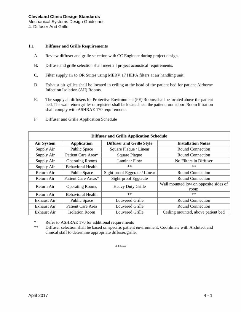
F. Diffuser and Grille Application Schedule
Diffuser and Grille Application Schedule
Air System Application Diffuser and Grille Style Installation Notes
Supply Air Public Space Square Plaque / Linear Round Connection
Supply Air Patient Care Area* Square Plaque Round Connection
Supply Air Operating Rooms Laminar Flow No Filters in Diffuser
Supply Air Behavioral Health ** **
Return Air Public Space Sight-proof Eggcrate / Linear Round Connection
Return Air Patient Care Areas* Sight-proof Eggcrate Round Connection
Return Air Operating Rooms Heavy Duty Grille Wall mounted low on opposite sides of
room
Return Air Behavioral Health ** **
Exhaust Air Public Space Louvered Grille Round Connection
Exhaust Air Patient Care Area Louvered Grille Round Connection
Exhaust Air Isolation Room Louvered Grille Ceiling mounted, above patient bed
* Refer to ASHRAE 170 for additional requirements
** Diffuser selection shall be based on specific patient environment. Coordinate with Architect and
clinical staff to determine appropriate diffuser/grille.
*****
Cleveland Clinic Design Standards Mechanical Systems Design Guidelines 5. HVAC Hydronic Distribution
April 2017 5 - 1
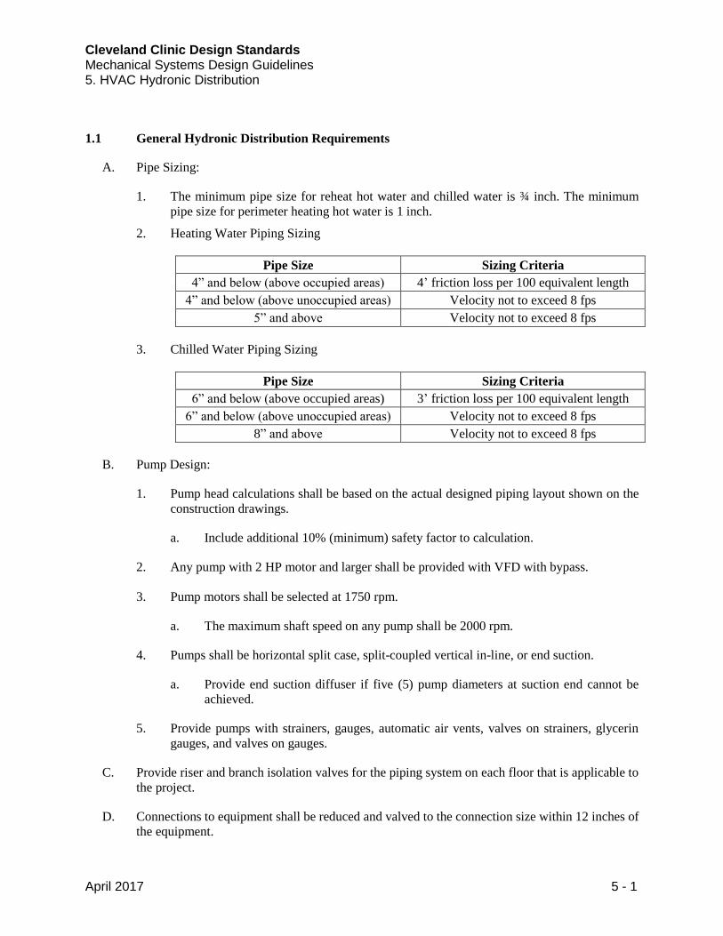
1.1 General Hydronic Distribution Requirements
A. Pipe Sizing:
1. The minimum pipe size for reheat hot water and chilled water is ¾ inch. The minimum
pipe size for perimeter heating hot water is 1 inch.
2. Heating Water Piping Sizing
Pipe Size Sizing Criteria
4” and below (above occupied areas) 4’ friction loss per 100 equivalent length
4” and below (above unoccupied areas) Velocity not to exceed 8 fps
5” and above Velocity not to exceed 8 fps
3. Chilled Water Piping Sizing
Pipe Size Sizing Criteria
6” and below (above occupied areas) 3’ friction loss per 100 equivalent length
6” and below (above unoccupied areas) Velocity not to exceed 8 fps
8” and above Velocity not to exceed 8 fps
B. Pump Design:
1. Pump head calculations shall be based on the actual designed piping layout shown on the
construction drawings.
a. Include additional 10% (minimum) safety factor to calculation.
2. Any pump with 2 HP motor and larger shall be provided with VFD with bypass.
3. Pump motors shall be selected at 1750 rpm.
a. The maximum shaft speed on any pump shall be 2000 rpm.
4. Pumps shall be horizontal split case, split-coupled vertical in-line, or end suction.
a. Provide end suction diffuser if five (5) pump diameters at suction end cannot be
achieved.
5. Provide pumps with strainers, gauges, automatic air vents, valves on strainers, glycerin
gauges, and valves on gauges.
C. Provide riser and branch isolation valves for the piping system on each floor that is applicable to
the project.
D. Connections to equipment shall be reduced and valved to the connection size within 12 inches of
the equipment.
Cleveland Clinic Design Standards Mechanical Systems Design Guidelines 5. HVAC Hydronic Distribution
April 2017 5 - 2
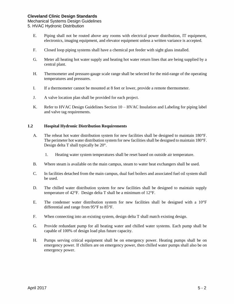
E. Piping shall not be routed above any rooms with electrical power distribution, IT equipment,
electronics, imaging equipment, and elevator equipment unless a written variance is accepted.
F. Closed loop piping systems shall have a chemical pot feeder with sight glass installed.
G. Meter all heating hot water supply and heating hot water return lines that are being supplied by a
central plant.
H. Thermometer and pressure-gauge scale range shall be selected for the mid-range of the operating
temperatures and pressures.
I. If a thermometer cannot be mounted at 8 feet or lower, provide a remote thermometer.
J. A valve location plan shall be provided for each project.
K. Refer to HVAC Design Guidelines Section 10 – HVAC Insulation and Labeling for piping label
and valve tag requirements.
1.2 Hospital Hydronic Distribution Requirements
A. The reheat hot water distribution system for new facilities shall be designed to maintain 180°F.
The perimeter hot water distribution system for new facilities shall be designed to maintain 180°F.
Design delta T shall typically be 20°.
1. Heating water system temperatures shall be reset based on outside air temperature.
B. Where steam is available on the main campus, steam to water heat exchangers shall be used.
C. In facilities detached from the main campus, dual fuel boilers and associated fuel oil system shall
be used.
D. The chilled water distribution system for new facilities shall be designed to maintain supply
temperature of 42°F. Design delta T shall be a minimum of 12°F.
E. The condenser water distribution system for new facilities shall be designed with a 10°F
differential and range from 95°F to 85°F.
F. When connecting into an existing system, design delta T shall match existing design.
G. Provide redundant pump for all heating water and chilled water systems. Each pump shall be
capable of 100% of design load plus future capacity.
H. Pumps serving critical equipment shall be on emergency power. Heating pumps shall be on
emergency power. If chillers are on emergency power, then chilled water pumps shall also be on
emergency power.
Cleveland Clinic Design Standards Mechanical Systems Design Guidelines 5. HVAC Hydronic Distribution
April 2017 5 - 3
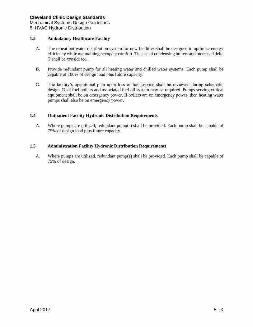
1.3 Ambulatory Healthcare Facility
A. The reheat hot water distribution system for new facilities shall be designed to optimize energy
efficiency while maintaining occupant comfort. The use of condensing boilers and increased delta
T shall be considered.
B. Provide redundant pump for all heating water and chilled water systems. Each pump shall be
capable of 100% of design load plus future capacity.
C. The facility’s operational plan upon loss of fuel service shall be reviewed during schematic
design. Dual fuel boilers and associated fuel oil system may be required. Pumps serving critical
equipment shall be on emergency power. If boilers are on emergency power, then heating water
pumps shall also be on emergency power.
1.4 Outpatient Facility Hydronic Distribution Requirements
A. Where pumps are utilized, redundant pump(s) shall be provided. Each pump shall be capable of
75% of design load plus future capacity.
1.5 Administration Facility Hydronic Distribution Requirements
A. Where pumps are utilized, redundant pump(s) shall be provided. Each pump shall be capable of
75% of design.
Cleveland Clinic Design Standards Mechanical Systems Design Guidelines 5. HVAC Hydronic Distribution
April 2017 5 - 4
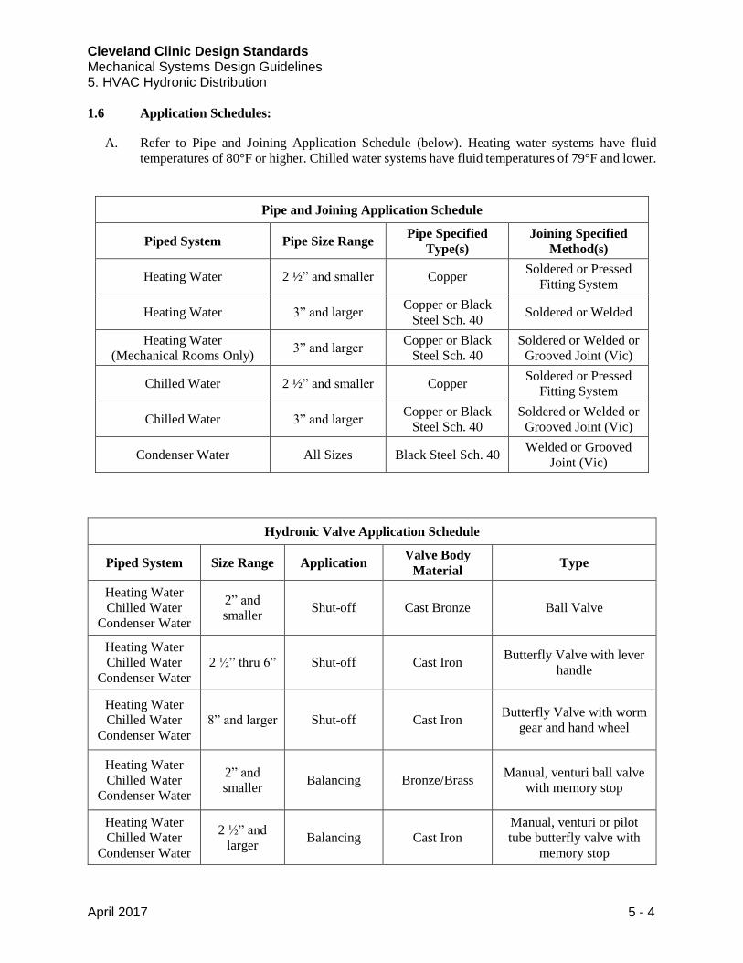
1.6 Application Schedules:
A. Refer to Pipe and Joining Application Schedule (below). Heating water systems have fluid
temperatures of 80°F or higher. Chilled water systems have fluid temperatures of 79°F and lower.
Pipe and Joining Application Schedule
Piped System Pipe Size Range Pipe Specified
Type(s)
Joining Specified
Method(s)
Heating Water 2 ½” and smaller Copper Soldered or Pressed
Fitting System
Heating Water 3” and larger Copper or Black
Steel Sch. 40 Soldered or Welded
Heating Water
(Mechanical Rooms Only) 3” and larger
Copper or Black
Steel Sch. 40
Soldered or Welded or
Grooved Joint (Vic)
Chilled Water 2 ½” and smaller Copper Soldered or Pressed
Fitting System
Chilled Water 3” and larger Copper or Black
Steel Sch. 40
Soldered or Welded or
Grooved Joint (Vic)
Condenser Water All Sizes Black Steel Sch. 40 Welded or Grooved
Joint (Vic)
Hydronic Valve Application Schedule
Piped System Size Range Application Valve Body
Material Type
Heating Water
Chilled Water
Condenser Water
2” and
smaller Shut-off Cast Bronze Ball Valve
Heating Water
Chilled Water
Condenser Water
2 ½” thru 6” Shut-off Cast Iron Butterfly Valve with lever
handle
Heating Water
Chilled Water
Condenser Water
8” and larger Shut-off Cast Iron Butterfly Valve with worm
gear and hand wheel
Heating Water
Chilled Water
Condenser Water
2” and
smaller Balancing Bronze/Brass
Manual, venturi ball valve
with memory stop
Heating Water
Chilled Water
Condenser Water
2 ½” and
larger Balancing Cast Iron
Manual, venturi or pilot
tube butterfly valve with
memory stop
Cleveland Clinic Design Standards Mechanical Systems Design Guidelines 5. HVAC Hydronic Distribution
April 2017 5 - 5
1.7 Manufacturers
Refer to CC Equipment Supplier List located on Buildings and Properties Website for acceptable
equipment manufacturers. (http://portals.clevelandclinic.org/ocm)
*****
Cleveland Clinic Design Standards Mechanical Systems Design Guidelines 6. Steam and Condensate
April 2017 6 - 1
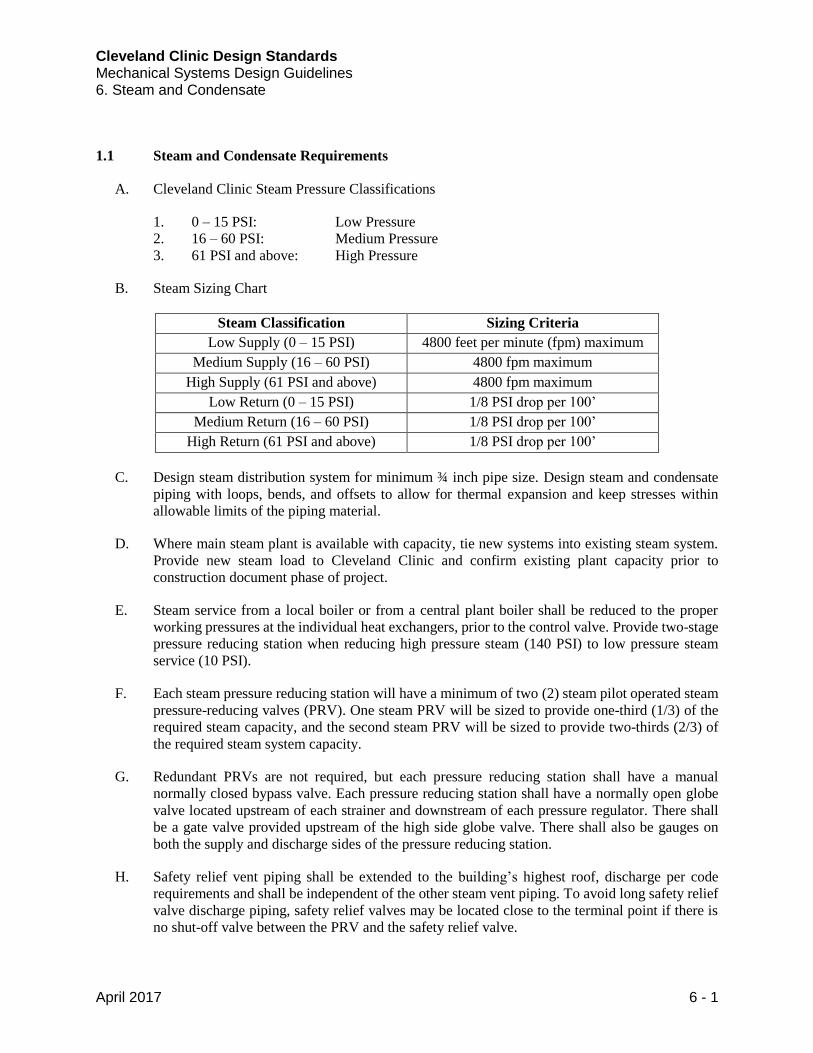
1.1 Steam and Condensate Requirements
A. Cleveland Clinic Steam Pressure Classifications
1. 0 – 15 PSI: Low Pressure
2. 16 – 60 PSI: Medium Pressure
3. 61 PSI and above: High Pressure
B. Steam Sizing Chart
Steam Classification Sizing Criteria
Low Supply (0 – 15 PSI) 4800 feet per minute (fpm) maximum
Medium Supply (16 – 60 PSI) 4800 fpm maximum
High Supply (61 PSI and above) 4800 fpm maximum
Low Return (0 – 15 PSI) 1/8 PSI drop per 100’
Medium Return (16 – 60 PSI) 1/8 PSI drop per 100’
High Return (61 PSI and above) 1/8 PSI drop per 100’
C. Design steam distribution system for minimum ¾ inch pipe size. Design steam and condensate
piping with loops, bends, and offsets to allow for thermal expansion and keep stresses within
allowable limits of the piping material.
D. Where main steam plant is available with capacity, tie new systems into existing steam system.
Provide new steam load to Cleveland Clinic and confirm existing plant capacity prior to
construction document phase of project.
E. Steam service from a local boiler or from a central plant boiler shall be reduced to the proper
working pressures at the individual heat exchangers, prior to the control valve. Provide two-stage
pressure reducing station when reducing high pressure steam (140 PSI) to low pressure steam
service (10 PSI).
F. Each steam pressure reducing station will have a minimum of two (2) steam pilot operated steam
pressure-reducing valves (PRV). One steam PRV will be sized to provide one-third (1/3) of the
required steam capacity, and the second steam PRV will be sized to provide two-thirds (2/3) of
the required steam system capacity.
G. Redundant PRVs are not required, but each pressure reducing station shall have a manual
normally closed bypass valve. Each pressure reducing station shall have a normally open globe
valve located upstream of each strainer and downstream of each pressure regulator. There shall
be a gate valve provided upstream of the high side globe valve. There shall also be gauges on
both the supply and discharge sides of the pressure reducing station.
H. Safety relief vent piping shall be extended to the building’s highest roof, discharge per code
requirements and shall be independent of the other steam vent piping. To avoid long safety relief
valve discharge piping, safety relief valves may be located close to the terminal point if there is
no shut-off valve between the PRV and the safety relief valve.
Cleveland Clinic Design Standards Mechanical Systems Design Guidelines 6. Steam and Condensate
April 2017 6 - 2
I. Avoid using expansion joints or ball joints if possible.
J. Steam traps shall be readily available for ease of maintenance. Bypass for steam trap is not
required.
K. Engineer shall submit steam piping stress analysis for all new steam piping installations.
L. Steam Testing Requirements
1. 100% of welds shall be visually inspected by installing contractor.
2. 10% of all welds shall be inspected via x-ray or ultrasonic testing.
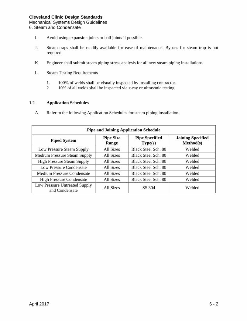
1.2 Application Schedules
A. Refer to the following Application Schedules for steam piping installation.
Pipe and Joining Application Schedule
Piped System Pipe Size
Range
Pipe Specified
Type(s)
Joining Specified
Method(s)
Low Pressure Steam Supply All Sizes Black Steel Sch. 80 Welded
Medium Pressure Steam Supply All Sizes Black Steel Sch. 80 Welded
High Pressure Steam Supply All Sizes Black Steel Sch. 80 Welded
Low Pressure Condensate All Sizes Black Steel Sch. 80 Welded
Medium Pressure Condensate All Sizes Black Steel Sch. 80 Welded
High Pressure Condensate All Sizes Black Steel Sch. 80 Welded
Low Pressure Untreated Supply
and Condensate All Sizes SS 304 Welded
Cleveland Clinic Design Standards Mechanical Systems Design Guidelines 6. Steam and Condensate
April 2017 6 - 3
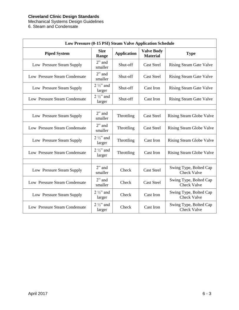
Low Pressure (0-15 PSI) Steam Valve Application Schedule
Piped System Size
Range Application
Valve Body
Material Type
Low Pressure Steam Supply 2” and
smaller Shut-off Cast Steel Rising Steam Gate Valve
Low Pressure Steam Condensate 2” and
smaller Shut-off Cast Steel Rising Steam Gate Valve
Low Pressure Steam Supply 2 ½” and
larger Shut-off Cast Iron Rising Steam Gate Valve
Low Pressure Steam Condensate 2 ½” and
larger Shut-off Cast Iron Rising Steam Gate Valve
Low Pressure Steam Supply 2” and
smaller Throttling Cast Steel Rising Steam Globe Valve
Low Pressure Steam Condensate 2” and
smaller Throttling Cast Steel Rising Steam Globe Valve
Low Pressure Steam Supply 2 ½” and
larger Throttling Cast Iron Rising Steam Globe Valve
Low Pressure Steam Condensate 2 ½” and
larger Throttling Cast Iron Rising Steam Globe Valve
Low Pressure Steam Supply 2” and
smaller Check Cast Steel
Swing Type, Bolted Cap
Check Valve
Low Pressure Steam Condensate 2” and
smaller Check Cast Steel
Swing Type, Bolted Cap
Check Valve
Low Pressure Steam Supply 2 ½” and
larger Check Cast Iron
Swing Type, Bolted Cap
Check Valve
Low Pressure Steam Condensate 2 ½” and
larger Check Cast Iron
Swing Type, Bolted Cap
Check Valve

Cleveland Clinic Design Standards Mechanical Systems Design Guidelines 6. Steam and Condensate
April 2017 6 - 4
Medium Pressure (16-60 PSI) Steam Valve Application Schedule
Piped System Size
Range Application
Valve Body
Material Type
Medium Pressure Steam Supply 2” and
smaller Shut-off Cast Steel Rising Steam Gate Valve
Medium Pressure Steam Condensate 2” and
smaller Shut-off Cast Steel Rising Steam Gate Valve
Medium Pressure Steam Supply 2 ½” and
larger Shut-off Cast Steel Rising Steam Gate Valve
Medium Pressure Steam Condensate 2 ½” and
larger Shut-off Cast Steel Rising Steam Gate Valve
Medium Pressure Steam Supply 2” and
smaller Throttling Cast Steel Rising Steam Globe Valve
Medium Pressure Steam Condensate 2” and
smaller Throttling Cast Steel Rising Steam Globe Valve
Medium Pressure Steam Supply 2 ½” and
larger Throttling Cast Steel Rising Steam Globe Valve
Medium Pressure Steam Condensate 2 ½” and
larger Throttling Cast Steel Rising Steam Globe Valve
Medium Pressure Steam Supply 2” and
smaller Check Cast Steel
Swing Type, Bolted Cap
Check Valve
Medium Pressure Steam Condensate 2” and
smaller Check Cast Steel
Swing Type, Bolted Cap
Check Valve
Medium Pressure Steam Supply 2 ½” and
larger Check Cast Steel
Swing Type, Bolted Cap
Check Valve
Medium Pressure Steam Condensate 2 ½” and
larger Check Cast Steel
Swing Type, Bolted Cap
Check Valve
Cleveland Clinic Design Standards Mechanical Systems Design Guidelines 6. Steam and Condensate
April 2017 6 - 5
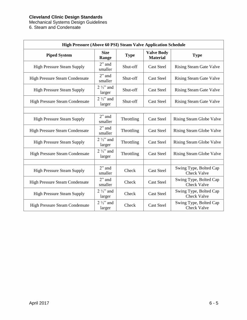
High Pressure (Above 60 PSI) Steam Valve Application Schedule
Piped System Size
Range Type
Valve Body
Material Type
High Pressure Steam Supply 2” and
smaller Shut-off Cast Steel Rising Steam Gate Valve
High Pressure Steam Condensate 2” and
smaller Shut-off Cast Steel Rising Steam Gate Valve
High Pressure Steam Supply 2 ½” and
larger Shut-off Cast Steel Rising Steam Gate Valve
High Pressure Steam Condensate 2 ½” and
larger Shut-off Cast Steel Rising Steam Gate Valve
High Pressure Steam Supply 2” and
smaller Throttling Cast Steel Rising Steam Globe Valve
High Pressure Steam Condensate 2” and
smaller Throttling Cast Steel Rising Steam Globe Valve
High Pressure Steam Supply 2 ½” and
larger Throttling Cast Steel Rising Steam Globe Valve
High Pressure Steam Condensate 2 ½” and
larger Throttling Cast Steel Rising Steam Globe Valve
High Pressure Steam Supply 2” and
smaller Check Cast Steel
Swing Type, Bolted Cap
Check Valve
High Pressure Steam Condensate 2” and
smaller Check Cast Steel
Swing Type, Bolted Cap
Check Valve
High Pressure Steam Supply 2 ½” and
larger Check Cast Steel
Swing Type, Bolted Cap
Check Valve
High Pressure Steam Condensate 2 ½” and
larger Check Cast Steel
Swing Type, Bolted Cap
Check Valve
Cleveland Clinic Design Standards Mechanical Systems Design Guidelines 6. Steam and Condensate
April 2017 6 - 6
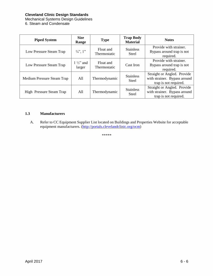
Piped System Size
Range Type
Trap Body
Material Notes
Low Pressure Steam Trap ¾”, 1” Float and
Thermostatic
Stainless
Steel
Provide with strainer.
Bypass around trap is not
required.
Low Pressure Steam Trap 1 ½” and
larger
Float and
Thermostatic Cast Iron
Provide with strainer.
Bypass around trap is not
required.
Medium Pressure Steam Trap All Thermodynamic Stainless
Steel
Straight or Angled. Provide
with strainer. Bypass around
trap is not required.
High Pressure Steam Trap All Thermodynamic Stainless
Steel
Straight or Angled. Provide
with strainer. Bypass around
trap is not required.
1.3 Manufacturers
A. Refer to CC Equipment Supplier List located on Buildings and Properties Website for acceptable
equipment manufacturers. (http://portals.clevelandclinic.org/ocm)
*****
Cleveland Clinic Design Standards Mechanical Systems Design Guidelines 7. Boilers Design
April 2017 7 - 1
1.1 General Boiler Requirements
A. Facility emergency operational plan shall be reviewed and documented with CC Owner’s
Representative and Engineer during design phase of project. The emergency operational plan
shall determine if dual-fuel boilers are required for facilities other than hospitals.
B. Where campus main plant steam is available, tie new systems into existing steam system. Provide
new steam load to CC Engineer and confirm existing plant has additional capacity prior to
construction document phase of project.
1. Campus steam shall be used as a heating medium for the following applications:
a. Heating Hot Water
b. Food Service (non-contract, as applicable)
c. Domestic Hot Water
d. Humidification
e. Autoclaves and Sterilizers
1.2 Hospital Boiler Requirements
A. Heating systems shall include 20% extra capacity for future renovations.
B. Where plant steam is unavailable, HVAC heating water shall be produced using high efficiency,
dual fuel heaters/boilers.
1. Fire tube boilers are preferred for individual building projects.
2. Central plant boilers shall be water tube.
3. Condensing style boilers shall be considered for increased efficiency, but return water
temperature system shall be designed for optimum boiler efficiency.
C. Provide redundant boiler sized at 100% of building’s peak heating load and future capacity.
D. Where steam generation is required or chosen due to existing systems, process needs, and/or
humidification:
1. All boilers shall a minimum of 10:1 turndown capability.
2. Provide high efficiency heat recovery systems (e.g. two-stage flue gas recovery) for steam
generating equipment to achieve high efficiency condensing operation.
3. Use blowdown separator/recovery units where possible to preheat make-up water to boiler
system/deaerator. Size blowdown separator/recovery unit to reduce blowdown water
temperature below 140°F prior to discharge of water to sanitary drainage system without
the addition of potable water. Breech heaters are acceptable. Continuous blowdown heaters
are not acceptable.
4. Use flue gas recovery heat exchangers to preheat boiler feed water (and/or serve other
heating loads where applicable). Use two-stage flue gas recovery (condensing) where
possible to further increase boiler efficiency. Where recovery systems result in condensing
of flue gases, design the boiler system with appropriate venting materials, proper sloping,
Cleveland Clinic Design Standards Mechanical Systems Design Guidelines 7. Boilers Design
April 2017 7 - 2
and sufficient removal of condensate. Second stage of heat recovery may be associated
with lower temperature heat requirements (e.g., HVAC heating hot water, domestic hot
water, desiccant reactivation, etc.). Equipment sizing should not be based on the
assumption that heat recovery will be available.
E. Central plant boilers shall be sized under EPA NOx limit so that NOx monitoring is not required.
F. Provide gas and oil meters for the boiler installation.
1. Provide a gas meter at the building(s). Install oil meters in both the supply line and the
return line of each storage tank. At least one (1) of the oil meters shall be a non-resettable
mechanical type.
2. Each boiler must be equipped with a natural gas totalizer for each boiler.
1.3 Ambulatory Healthcare Facility Boiler Requirements
A. Heating systems shall include 10-15% extra capacity for future renovations. Extra capacity shall
be reviewed with CC Engineer during project design.
B. Dual fuel requirement shall be determined based on facility’s emergency operational plan.
1. If dual fuel is required, boiler requirements shall match those listed in Hospital
Requirements.
2. If dual fuel is not required, HVAC heating water shall be produced using high efficiency,
natural gas fired boilers.
a. Condensing style boilers shall be considered for increased efficiency, but return
water temperature system shall be designed for optimum boiler efficiency.
1.4 Outpatient Facility Boiler Requirements
A. Heating systems shall include 5-10% extra capacity for future renovations. Extra capacity shall
be reviewed with CC Engineer during project design.
B. Dual fuel will not typically be required, but shall be reviewed with CC Engineer during project
design.
C. Condensing style boilers shall be considered for increased efficiency, but return water
temperature system shall be designed for optimum boiler efficiency.
1.5 Administration Facility Boiler Requirements
A. Review boiler redundancy requirements with CC Engineer during project design.
B. If heating water is utilized, HVAC heating water hot water shall be produced using high
efficiency, natural gas fired boilers.
Cleveland Clinic Design Standards Mechanical Systems Design Guidelines 7. Boilers Design
April 2017 7 - 3
1. Condensing style boilers shall be considered for increased efficiency, but return water
temperature system shall be designed for optimum boiler efficiency.
1.6 Manufacturers
A. Refer to CC Equipment Supplier List located on Buildings and Properties Website for acceptable
equipment manufacturers. (http://portals.clevelandclinic.org/ocm)
*****
Cleveland Clinic Design Standards Mechanical Systems Design Guidelines 8. Heat Exchangers for HVAC
April 2017 8 - 1
1.1 Heat Exchangers for HVAC General Requirements
A. When building is connected to campus steam, heating hot water shall be produced by steam to
hot water heat exchangers.
1.2 Hospital Heat Exchanger Requirements
A. Heating systems shall include 20% extra capacity for future renovations.
B. The building shall be supplied with a fully redundant heating system, including heat exchangers
and pumps. Heat exchangers shall be designed to supply 180°F at the required flow rate (GPM)
of heating hot water to the building.
C. Heat exchangers for building heating applications shall be steam to hot water using shell and
tube configuration. The tubes shall be CU-Ni (80-20), copper (18 gauge) or stainless steel (type
304). Baffle plates to be stainless steel within the heat exchanger.
1.3 Ambulatory Healthcare Facility Heat Exchanger Requirements
A. Heating systems shall include 10-15% extra capacity for future renovations. Extra capacity shall
be reviewed with CC Engineer during project design.
B. If heat exchangers are utilized, Hospital requirements shall be followed.
1.4 Outpatient Facility Heat Exchanger Requirements
A. Heating systems shall include 5-10% extra capacity for future renovations. Extra capacity shall
be reviewed with CC Engineer during project design.
B. If heat exchangers are utilized, Hospital requirements shall be followed.
1.5 Administration Facility Heat Exchanger Requirements
A. System shall be reviewed with CC Engineer during project design. Heat exchangers will
typically not be utilized.
1.6 Manufacturers
A. Refer to CC Equipment Supplier List located on Buildings and Properties Website for
acceptable equipment manufacturers. (http://portals.clevelandclinic.org/ocm)
*****
Cleveland Clinic Design Standards Mechanical Systems Design Guidelines 9. Chillers and Associated Equipment Design
April 2017 9 - 1
1.1 Chillers and Associated Equipment General Requirements
A. The selection of a specific refrigeration chiller design requires careful analysis. The following
parameters should be considered when determining what type of chiller to use:
1. Life cycle cost analysis of different types of chillers
2. Capacity
3. Application of service
4. New system or addition to existing system
B. Chiller replacements that are part of an existing building renovation project shall comply with
state code requirements pertaining to mechanical rooms that have existing chillers and boilers in
the same room with no physical barriers between them.
C. Provisions shall be made during design to install chillers and associated equipment in a separate
room from boiler.
D. Process equipment (IT equipment and/or medical equipment) shall not be placed on the comfort
chilled water loop.
E. Provide emergency chilled water flanged piping connections covered with blind flanges and
isolation valves for emergency chilled water service where redundant chillers are not installed.
F. Chiller staging shall be performed to optimize chiller efficiency.
G. When laying out equipment, provide ample space to service and repair equipment. Required
service access and tube-pull space shall be clearly shown on the drawings with a dashed line.
H. For new chiller plant construction, provide a designated space, shown on the drawings, for future
chiller(s), equal in size to the largest machine being furnished. Space planning should also be
considered with associated pumps, cooling tower, and other equipment to support additional
chiller(s).
I. Evaluate sound requirements per job. Chiller design shall comply with all acoustical and vibration
requirements listed in FGI Guidelines. Provide sound barrier covers where applicable.
1.2 Hospital Chillers and Associated Equipment Requirements
A. Cooling systems shall include 20% extra capacity for future renovations.
B. Baseline design for a hospital shall be water-cooled chiller(s) and associated cooling tower(s).
1. New pumping configurations shall be variable primary.
2. Hospitals shall be provided with a redundant chiller and associated cooling tower, pumps,
etc., sized at 100% of design load plus future capacity, an N+1 configuration for the chiller
plant.
Cleveland Clinic Design Standards Mechanical Systems Design Guidelines 9. Chillers and Associated Equipment Design
April 2017 9 - 2
C. Emergency power shall be available to the appropriate number of chillers to support ventilation
environments for all patient care facilities, laboratories, or viviariums.
1. All chilled water emergency power requirements shall be reviewed and approved by CC
Engineer during design. A steam driven turbine chiller can be considered based on LCCA
and availability of emergency power.
D. Chiller Design
1. For a new chilled water plant, select a minimum of two (2) chillers identical in size and
design. If anticipated part-load conditions justify chiller selection of uneven sizes, the
Design Team shall prepare a cooling load profile to demonstrate selection of chiller sizes.
Identify where chiller(s) are used in heat pump applications.
2. During periods when the chilling system is operating with the outdoor wet bulb temperature
below design, condenser water supply temperature setpoint is to be reset to track the
cooling tower’s wet bulb temperature approach line prescribed by the cooling tower
manufacturer. During condenser water supply reset periods, chiller minimum condenser
water supply temperatures (and minimum pressure differentials between evaporators and
condensers) shall be respected to prevent surging of refrigeration machines. Intent is to
reduce chiller lift and compressor head pressures during periods when outdoor wet bulb
temperature is below design values.
3. Condenser and chilled water piping (where marine water boxes are not specified or used)
shall be fabricated into removable spool piece sections to permit easier access to tube
bundles in the condenser and evaporator sections.
4. A solids separator shall be provided for each chilled water system.
5. Specify pre-insulated chilled water piping for underground piping.
E. Process Chiller Design
1. Process chilled water systems may serve IT cooling loads and/or medical equipment loads.
2. A process chiller shall have multiple, independent circuits for redundancy. Review level of
redundancy with CC Engineer during design. A redundant process chiller may be required
in specific applications.
3. Process chillers shall be air-cooled. In cold weather climates, chiller shall be provided with
economizer coil. Economizer coil reduces cold weather operational issues.
4. Provide redundant pumps for each process loop. Critical process loops may have city water
back-up connection.
F. Cooling Tower Design
1. Cooling towers shall be vertical crossflow utilizing variable speed propeller fans with a
minimum of two (2) cells with the ability to isolate the tower basins.
2. Provide stainless steel tower basins.
3. At facilities in cold weather climates (where freezing may occur):
a. Indoor cooling tower basin is preferred.
b. If basin is located outdoors, basin heaters shall be provided.
4. Cooling tower redundancy and additional capacity shall match chiller design.
Cleveland Clinic Design Standards Mechanical Systems Design Guidelines 9. Chillers and Associated Equipment Design
April 2017 9 - 3
5. For cooling towers with multiple tower cells:
a. An equalizing line shall be provided between cells.
b. Cooling tower basin water level controls are to be provided for each individual
cooling tower cell.
c. Basin isolation gates are to be provided between combined tower cells to permit
maintenance to be performed on one tower cell while the adjacent cell is in
operation. A compete system shutdown for maintenance is NOT acceptable.
6. If the maximum cooling tower tonnage is at or near the capacity limit of a selection, the
next larger size of tower shall be selected.
7. Cooling tower blowdown drains are to be routed to sanitary drains, and the catch basins
shall be sized for the proper capacity to manage surge flow conditions from peak cooling
tower blowdown to avoid overflow conditions.
8. Provide a side stream, solids separator on the condenser water side of the system.
9. An automatic cold water basin sediment removal system and filtration for evaporative
cooling towers shall be considered on a per project bases. Intent is to reduce cooling tower
maintenance, increase longevity, and reduce chemical water treatment (biocides).
10. Specify power operated tight, shut-off butterfly type valves to isolate the condenser water
and chilled water at the inlet connections to chiller, with the ability to manually override
the valve.
11. Elevated cooling towers require stairs, platforms, and access doorways to reach areas
outside and within the tower fill area for operation and maintenance.
1.3 Ambulatory Healthcare Facility Chiller and Associated Equipment Requirements
A. Cooling systems shall include 10-15% extra capacity for future renovations.
B. Baseline HVAC design for an ambulatory healthcare facility is DX cooling units. If chiller (and
associated components) is required, it shall meet Hospital requirements, except for future capacity
sizing.
C. Where available, connect facility to the campus centralized chiller water system.
D. Any chilled water emergency power requirements shall be reviewed and approved by CC
Engineer during design. Emergency power for cooling in patient care areas may be required.
1.4 Outpatient Facility Chiller and Associated Equipment Requirements
A. Cooling systems shall include 5-10% extra capacity for future renovations.
B. Baseline HVAC design for an outpatient facility is DX cooling units. If chiller (and associated
components) is required, it shall meet Hospital requirements, except for future capacity sizing.
1.5 Administration Facility Chiller and Associated Equipment Requirements
A. Baseline HVAC design for an administration building is DX cooling units.
Cleveland Clinic Design Standards Mechanical Systems Design Guidelines 9. Chillers and Associated Equipment Design
April 2017 9 - 4
1.6 Manufacturers
A. Refer to CC Equipment Supplier List located on Buildings and Properties Website for acceptable
equipment manufacturers. (http://portals.clevelandclinic.org/ocm)
*****
Cleveland Clinic Design Standards Mechanical Systems Design Guidelines 10. HVAC Insulation and Labeling
April 2017 10 - 1
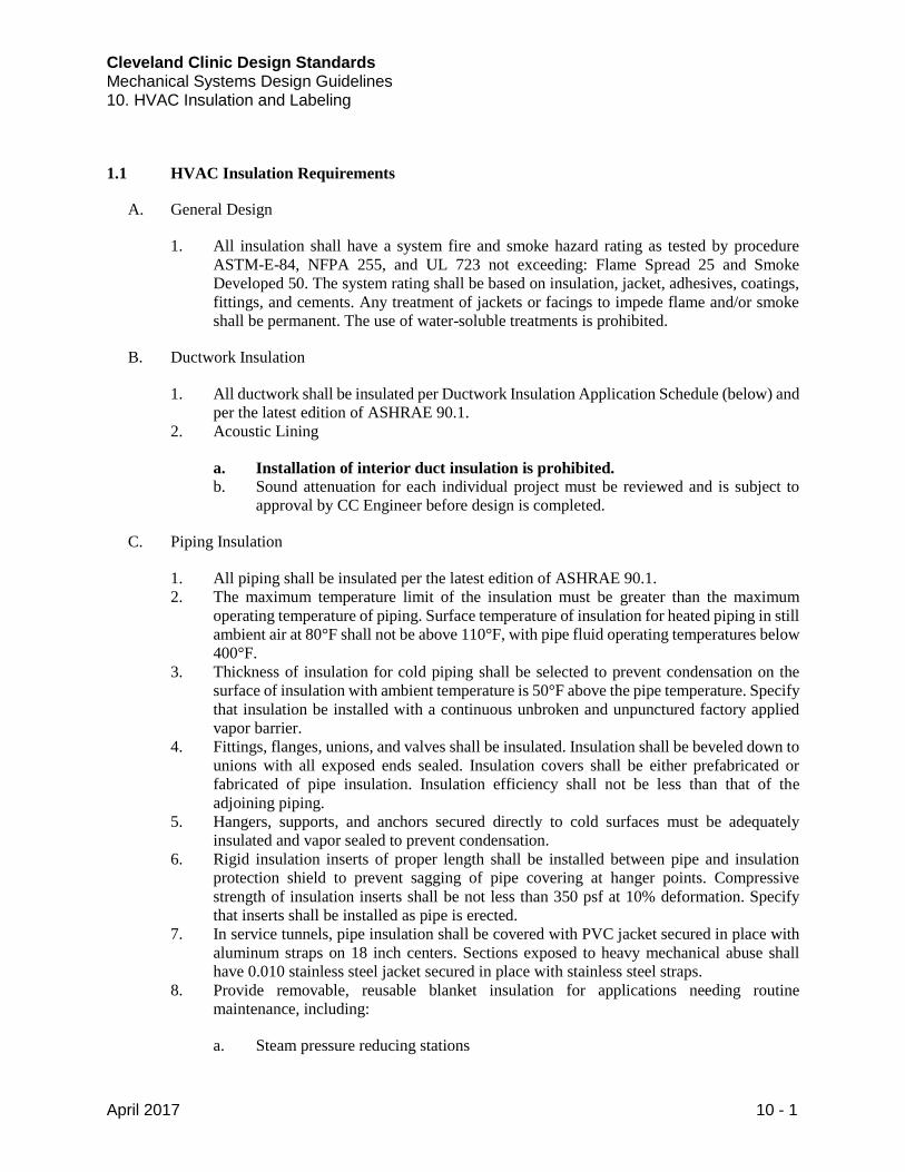
1.1 HVAC Insulation Requirements
A. General Design
1. All insulation shall have a system fire and smoke hazard rating as tested by procedure
ASTM-E-84, NFPA 255, and UL 723 not exceeding: Flame Spread 25 and Smoke
Developed 50. The system rating shall be based on insulation, jacket, adhesives, coatings,
fittings, and cements. Any treatment of jackets or facings to impede flame and/or smoke
shall be permanent. The use of water-soluble treatments is prohibited.
B. Ductwork Insulation
1. All ductwork shall be insulated per Ductwork Insulation Application Schedule (below) and
per the latest edition of ASHRAE 90.1.
2. Acoustic Lining
a. Installation of interior duct insulation is prohibited.
b. Sound attenuation for each individual project must be reviewed and is subject to
approval by CC Engineer before design is completed.
C. Piping Insulation
1. All piping shall be insulated per the latest edition of ASHRAE 90.1.
2. The maximum temperature limit of the insulation must be greater than the maximum
operating temperature of piping. Surface temperature of insulation for heated piping in still
ambient air at 80°F shall not be above 110°F, with pipe fluid operating temperatures below
400°F.
3. Thickness of insulation for cold piping shall be selected to prevent condensation on the
surface of insulation with ambient temperature is 50°F above the pipe temperature. Specify
that insulation be installed with a continuous unbroken and unpunctured factory applied
vapor barrier.
4. Fittings, flanges, unions, and valves shall be insulated. Insulation shall be beveled down to
unions with all exposed ends sealed. Insulation covers shall be either prefabricated or
fabricated of pipe insulation. Insulation efficiency shall not be less than that of the
adjoining piping.
5. Hangers, supports, and anchors secured directly to cold surfaces must be adequately
insulated and vapor sealed to prevent condensation.
6. Rigid insulation inserts of proper length shall be installed between pipe and insulation
protection shield to prevent sagging of pipe covering at hanger points. Compressive
strength of insulation inserts shall be not less than 350 psf at 10% deformation. Specify
that inserts shall be installed as pipe is erected.
7. In service tunnels, pipe insulation shall be covered with PVC jacket secured in place with
aluminum straps on 18 inch centers. Sections exposed to heavy mechanical abuse shall
have 0.010 stainless steel jacket secured in place with stainless steel straps.
8. Provide removable, reusable blanket insulation for applications needing routine
maintenance, including:
a. Steam pressure reducing stations
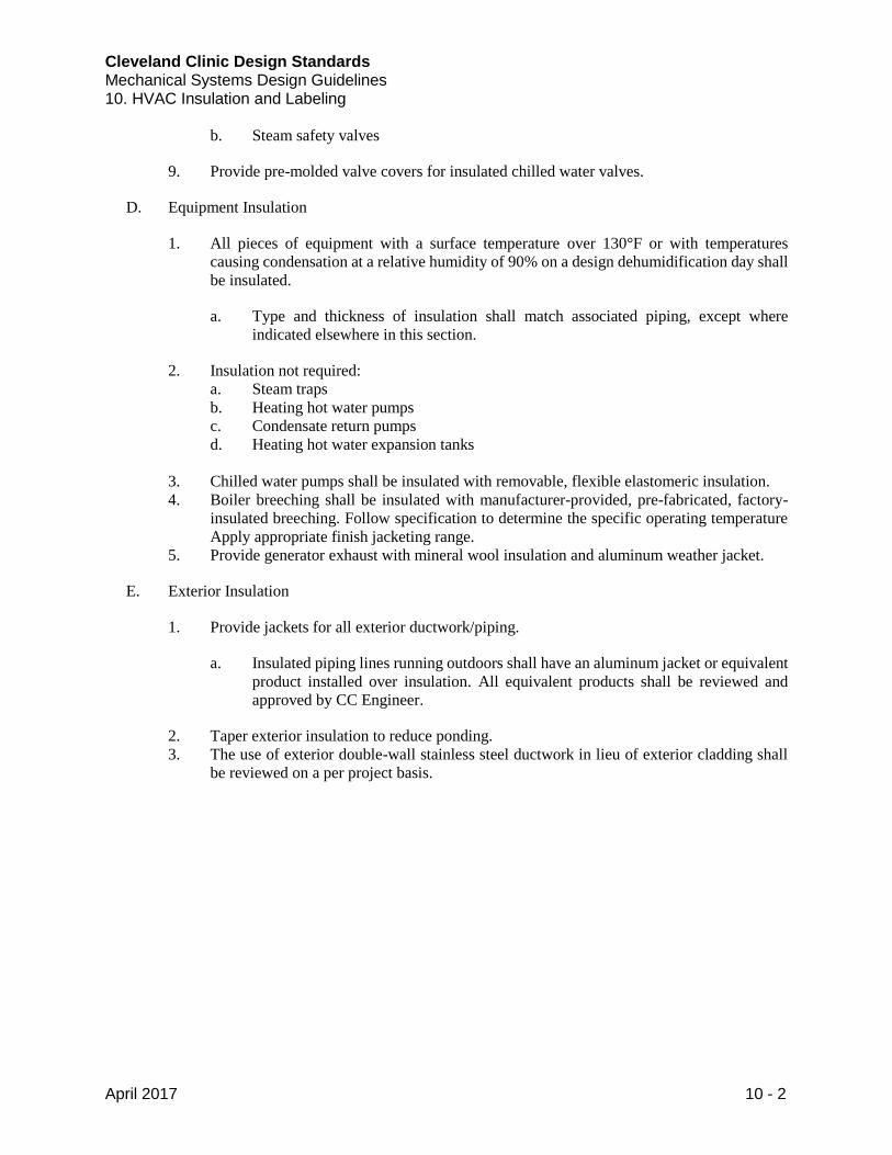
Cleveland Clinic Design Standards Mechanical Systems Design Guidelines 10. HVAC Insulation and Labeling
April 2017 10 - 2
b. Steam safety valves
9. Provide pre-molded valve covers for insulated chilled water valves.
D. Equipment Insulation
1. All pieces of equipment with a surface temperature over 130°F or with temperatures
causing condensation at a relative humidity of 90% on a design dehumidification day shall
be insulated.
a. Type and thickness of insulation shall match associated piping, except where
indicated elsewhere in this section.
2. Insulation not required:
a. Steam traps
b. Heating hot water pumps
c. Condensate return pumps
d. Heating hot water expansion tanks
3. Chilled water pumps shall be insulated with removable, flexible elastomeric insulation.
4. Boiler breeching shall be insulated with manufacturer-provided, pre-fabricated, factory-
insulated breeching. Follow specification to determine the specific operating temperature
Apply appropriate finish jacketing range.
5. Provide generator exhaust with mineral wool insulation and aluminum weather jacket.
E. Exterior Insulation
1. Provide jackets for all exterior ductwork/piping.
a. Insulated piping lines running outdoors shall have an aluminum jacket or equivalent
product installed over insulation. All equivalent products shall be reviewed and
approved by CC Engineer.
2. Taper exterior insulation to reduce ponding.
3. The use of exterior double-wall stainless steel ductwork in lieu of exterior cladding shall
be reviewed on a per project basis.
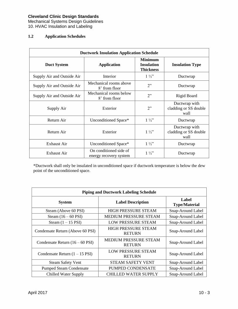
Cleveland Clinic Design Standards Mechanical Systems Design Guidelines 10. HVAC Insulation and Labeling
April 2017 10 - 3
1.2 Application Schedules
Ductwork Insulation Application Schedule
Duct System Application
Minimum
Insulation
Thickness
Insulation Type
Supply Air and Outside Air Interior 1 ½” Ductwrap
Supply Air and Outside Air Mechanical rooms above
8’ from floor 2” Ductwrap
Supply Air and Outside Air Mechanical rooms below
8’ from floor 2” Rigid Board
Supply Air Exterior 2”
Ductwrap with
cladding or SS double
wall
Return Air Unconditioned Space* 1 ½” Ductwrap
Return Air Exterior 1 ½”
Ductwrap with
cladding or SS double
wall
Exhaust Air Unconditioned Space* 1 ½” Ductwrap
Exhaust Air On conditioned side of
energy recovery system 1 ½” Ductwrap
*Ductwork shall only be insulated in unconditioned space if ductwork temperature is below the dew
point of the unconditioned space.
Piping and Ductwork Labeling Schedule
System Label Description Label
Type/Material
Steam (Above 60 PSI) HIGH PRESSURE STEAM Snap-Around Label
Steam (16 – 60 PSI) MEDIUM PRESSURE STEAM Snap-Around Label
Steam (1 – 15 PSI) LOW PRESSURE STEAM Snap-Around Label
Condensate Return (Above 60 PSI) HIGH PRESSURE STEAM
RETURN Snap-Around Label
Condensate Return (16 – 60 PSI) MEDIUM PRESSURE STEAM
RETURN Snap-Around Label
Condensate Return (1 – 15 PSI) LOW PRESSURE STEAM
RETURN Snap-Around Label
Steam Safety Vent STEAM SAFETY VENT Snap-Around Label
Pumped Steam Condensate PUMPED CONDENSATE Snap-Around Label
Chilled Water Supply CHILLED WATER SUPPLY Snap-Around Label
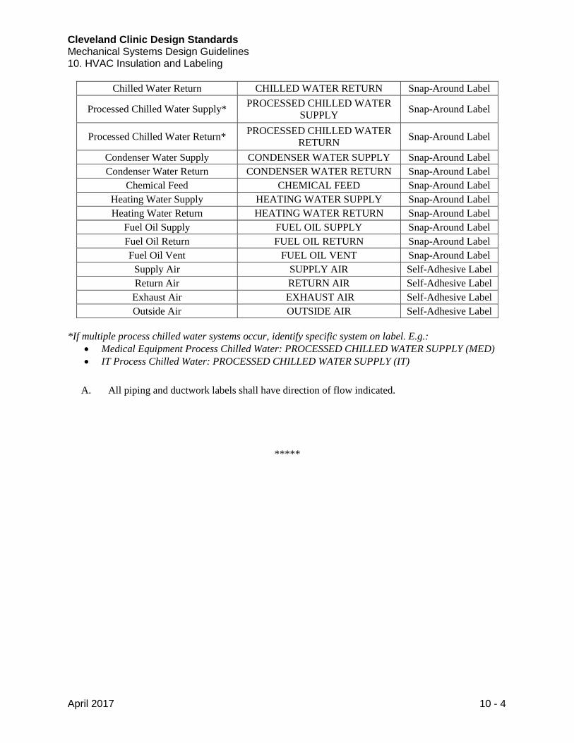
Cleveland Clinic Design Standards Mechanical Systems Design Guidelines 10. HVAC Insulation and Labeling
April 2017 10 - 4
Chilled Water Return CHILLED WATER RETURN Snap-Around Label
Processed Chilled Water Supply* PROCESSED CHILLED WATER
SUPPLY Snap-Around Label
Processed Chilled Water Return* PROCESSED CHILLED WATER
RETURN Snap-Around Label
Condenser Water Supply CONDENSER WATER SUPPLY Snap-Around Label
Condenser Water Return CONDENSER WATER RETURN Snap-Around Label
Chemical Feed CHEMICAL FEED Snap-Around Label
Heating Water Supply HEATING WATER SUPPLY Snap-Around Label
Heating Water Return HEATING WATER RETURN Snap-Around Label
Fuel Oil Supply FUEL OIL SUPPLY Snap-Around Label
Fuel Oil Return FUEL OIL RETURN Snap-Around Label
Fuel Oil Vent FUEL OIL VENT Snap-Around Label
Supply Air SUPPLY AIR Self-Adhesive Label
Return Air RETURN AIR Self-Adhesive Label
Exhaust Air EXHAUST AIR Self-Adhesive Label
Outside Air OUTSIDE AIR Self-Adhesive Label
*If multiple process chilled water systems occur, identify specific system on label. E.g.:
Medical Equipment Process Chilled Water: PROCESSED CHILLED WATER SUPPLY (MED)
IT Process Chilled Water: PROCESSED CHILLED WATER SUPPLY (IT)
A. All piping and ductwork labels shall have direction of flow indicated.
*****
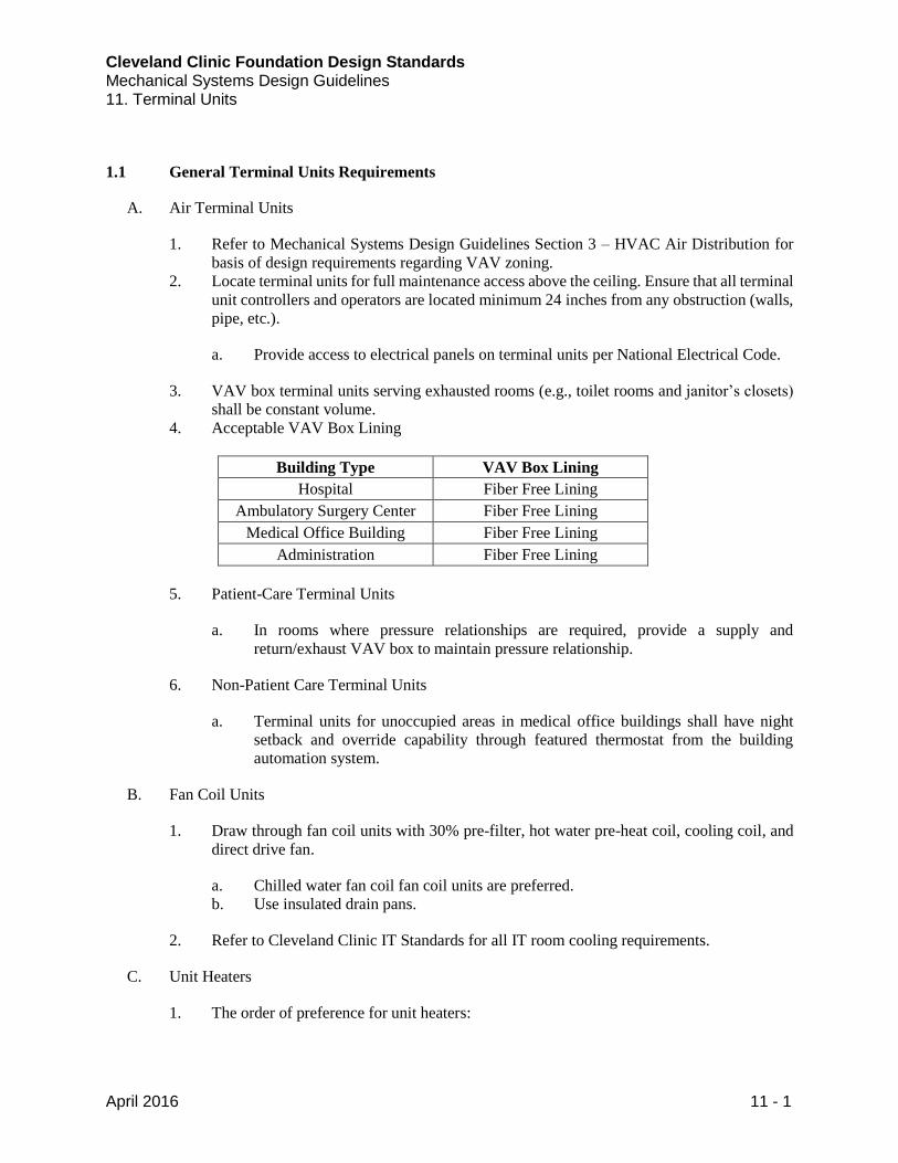
Cleveland Clinic Foundation Design Standards Mechanical Systems Design Guidelines 11. Terminal Units
April 2016 11 - 1
1.1 General Terminal Units Requirements
A. Air Terminal Units
1. Refer to Mechanical Systems Design Guidelines Section 3 – HVAC Air Distribution for
basis of design requirements regarding VAV zoning.
2. Locate terminal units for full maintenance access above the ceiling. Ensure that all terminal
unit controllers and operators are located minimum 24 inches from any obstruction (walls,
pipe, etc.).
a. Provide access to electrical panels on terminal units per National Electrical Code.
3. VAV box terminal units serving exhausted rooms (e.g., toilet rooms and janitor’s closets)
shall be constant volume.
4. Acceptable VAV Box Lining
Building Type VAV Box Lining
Hospital Fiber Free Lining
Ambulatory Surgery Center Fiber Free Lining
Medical Office Building Fiber Free Lining
Administration Fiber Free Lining
5. Patient-Care Terminal Units
a. In rooms where pressure relationships are required, provide a supply and
return/exhaust VAV box to maintain pressure relationship.
6. Non-Patient Care Terminal Units
a. Terminal units for unoccupied areas in medical office buildings shall have night
setback and override capability through featured thermostat from the building
automation system.
B. Fan Coil Units
1. Draw through fan coil units with 30% pre-filter, hot water pre-heat coil, cooling coil, and
direct drive fan.
a. Chilled water fan coil fan coil units are preferred.
b. Use insulated drain pans.
2. Refer to Cleveland Clinic IT Standards for all IT room cooling requirements.
C. Unit Heaters
1. The order of preference for unit heaters:
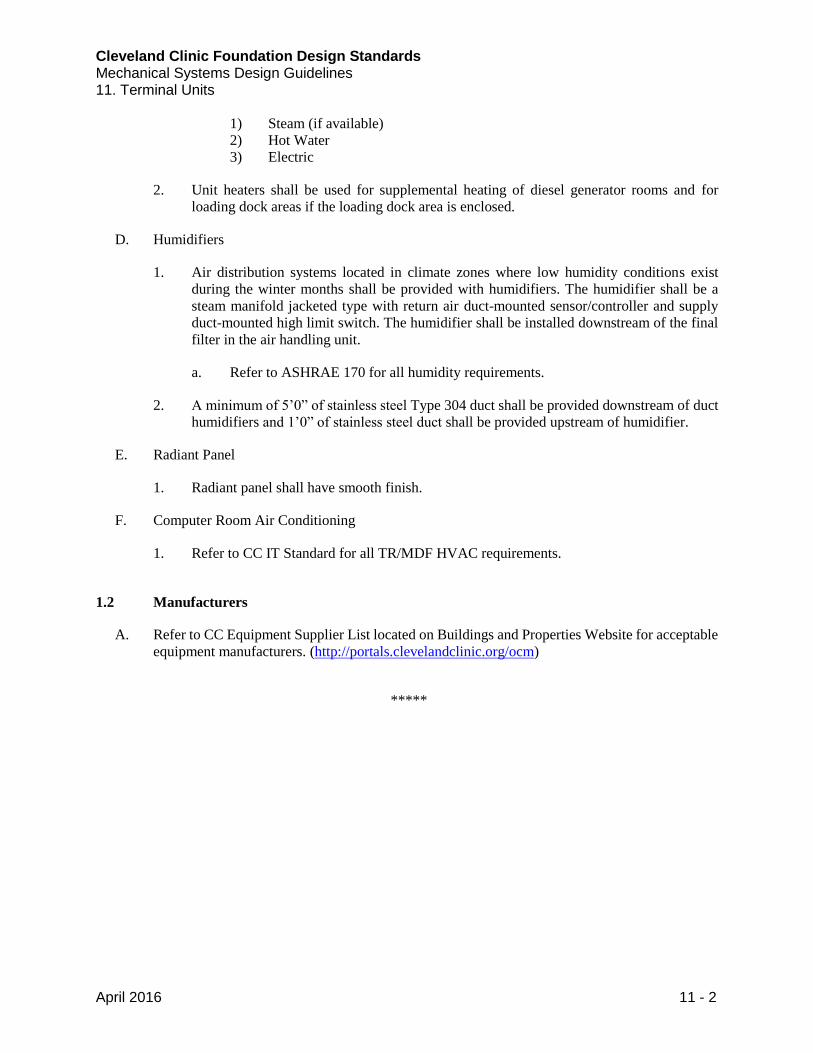
Cleveland Clinic Foundation Design Standards Mechanical Systems Design Guidelines 11. Terminal Units
April 2016 11 - 2
1) Steam (if available)
2) Hot Water
3) Electric
2. Unit heaters shall be used for supplemental heating of diesel generator rooms and for
loading dock areas if the loading dock area is enclosed.
D. Humidifiers
1. Air distribution systems located in climate zones where low humidity conditions exist
during the winter months shall be provided with humidifiers. The humidifier shall be a
steam manifold jacketed type with return air duct-mounted sensor/controller and supply
duct-mounted high limit switch. The humidifier shall be installed downstream of the final
filter in the air handling unit.
a. Refer to ASHRAE 170 for all humidity requirements.
2. A minimum of 5’0” of stainless steel Type 304 duct shall be provided downstream of duct
humidifiers and 1’0” of stainless steel duct shall be provided upstream of humidifier.
E. Radiant Panel
1. Radiant panel shall have smooth finish.
F. Computer Room Air Conditioning
1. Refer to CC IT Standard for all TR/MDF HVAC requirements.
1.2 Manufacturers
A. Refer to CC Equipment Supplier List located on Buildings and Properties Website for acceptable
equipment manufacturers. (http://portals.clevelandclinic.org/ocm)
*****
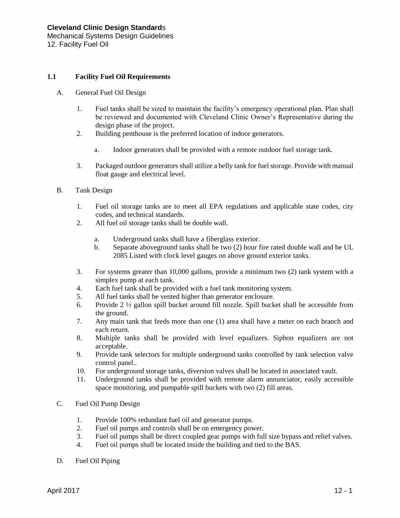
Cleveland Clinic Design Standards Mechanical Systems Design Guidelines 12. Facility Fuel Oil
April 2017 12 - 1
1.1 Facility Fuel Oil Requirements
A. General Fuel Oil Design
1. Fuel tanks shall be sized to maintain the facility’s emergency operational plan. Plan shall
be reviewed and documented with Cleveland Clinic Owner’s Representative during the
design phase of the project.
2. Building penthouse is the preferred location of indoor generators.
a. Indoor generators shall be provided with a remote outdoor fuel storage tank.
3. Packaged outdoor generators shall utilize a belly tank for fuel storage. Provide with manual
float gauge and electrical level.
B. Tank Design
1. Fuel oil storage tanks are to meet all EPA regulations and applicable state codes, city
codes, and technical standards.
2. All fuel oil storage tanks shall be double wall.
a. Underground tanks shall have a fiberglass exterior.
b. Separate aboveground tanks shall be two (2) hour fire rated double wall and be UL
2085 Listed with clock level gauges on above ground exterior tanks.
3. For systems greater than 10,000 gallons, provide a minimum two (2) tank system with a
simplex pump at each tank.
4. Each fuel tank shall be provided with a fuel tank monitoring system.
5. All fuel tanks shall be vented higher than generator enclosure.
6. Provide 2 ½ gallon spill bucket around fill nozzle. Spill bucket shall be accessible from
the ground.
7. Any main tank that feeds more than one (1) area shall have a meter on each branch and
each return.
8. Multiple tanks shall be provided with level equalizers. Siphon equalizers are not
acceptable.
9. Provide tank selectors for multiple underground tanks controlled by tank selection valve
control panel..
10. For underground storage tanks, diversion valves shall be located in associated vault.
11. Underground tanks shall be provided with remote alarm annunciator, easily accessible
space monitoring, and pumpable spill buckets with two (2) fill areas.
C. Fuel Oil Pump Design
1. Provide 100% redundant fuel oil and generator pumps.
2. Fuel oil pumps and controls shall be on emergency power.
3. Fuel oil pumps shall be direct coupled gear pumps with full size bypass and relief valves.
4. Fuel oil pumps shall be located inside the building and tied to the BAS.
D. Fuel Oil Piping
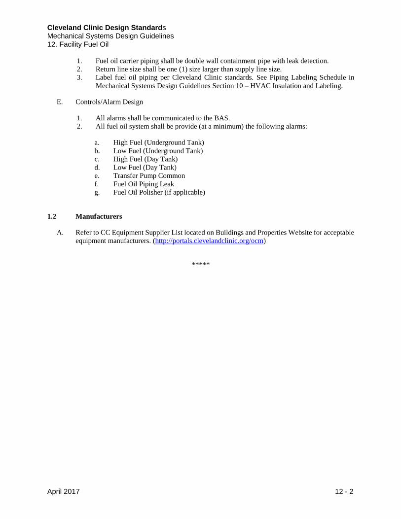
Cleveland Clinic Design Standards Mechanical Systems Design Guidelines 12. Facility Fuel Oil
April 2017 12 - 2
1. Fuel oil carrier piping shall be double wall containment pipe with leak detection.
2. Return line size shall be one (1) size larger than supply line size.
3. Label fuel oil piping per Cleveland Clinic standards. See Piping Labeling Schedule in
Mechanical Systems Design Guidelines Section 10 – HVAC Insulation and Labeling.
E. Controls/Alarm Design
1. All alarms shall be communicated to the BAS.
2. All fuel oil system shall be provide (at a minimum) the following alarms:
a. High Fuel (Underground Tank)
b. Low Fuel (Underground Tank)
c. High Fuel (Day Tank)
d. Low Fuel (Day Tank)
e. Transfer Pump Common
f. Fuel Oil Piping Leak
g. Fuel Oil Polisher (if applicable)
1.2 Manufacturers
A. Refer to CC Equipment Supplier List located on Buildings and Properties Website for acceptable
equipment manufacturers. (http://portals.clevelandclinic.org/ocm)
*****
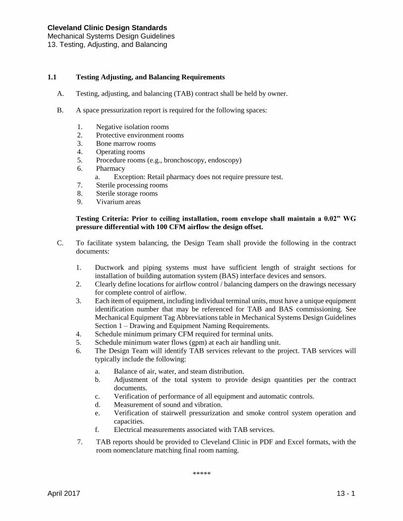
Cleveland Clinic Design Standards Mechanical Systems Design Guidelines 13. Testing, Adjusting, and Balancing
April 2017 13 - 1
1.1 Testing Adjusting, and Balancing Requirements
A. Testing, adjusting, and balancing (TAB) contract shall be held by owner.
B. A space pressurization report is required for the following spaces:
1. Negative isolation rooms
2. Protective environment rooms
3. Bone marrow rooms
4. Operating rooms
5. Procedure rooms (e.g., bronchoscopy, endoscopy)
6. Pharmacy
a. Exception: Retail pharmacy does not require pressure test.
7. Sterile processing rooms
8. Sterile storage rooms
9. Vivarium areas
Testing Criteria: Prior to ceiling installation, room envelope shall maintain a 0.02” WG
pressure differential with 100 CFM airflow the design offset.
C. To facilitate system balancing, the Design Team shall provide the following in the contract
documents:
1. Ductwork and piping systems must have sufficient length of straight sections for
installation of building automation system (BAS) interface devices and sensors.
2. Clearly define locations for airflow control / balancing dampers on the drawings necessary
for complete control of airflow.
3. Each item of equipment, including individual terminal units, must have a unique equipment
identification number that may be referenced for TAB and BAS commissioning. See
Mechanical Equipment Tag Abbreviations table in Mechanical Systems Design Guidelines
Section 1 – Drawing and Equipment Naming Requirements.
4. Schedule minimum primary CFM required for terminal units.
5. Schedule minimum water flows (gpm) at each air handling unit.
6. The Design Team will identify TAB services relevant to the project. TAB services will
typically include the following:
a. Balance of air, water, and steam distribution.
b. Adjustment of the total system to provide design quantities per the contract
documents.
c. Verification of performance of all equipment and automatic controls.
d. Measurement of sound and vibration.
e. Verification of stairwell pressurization and smoke control system operation and
capacities.
f. Electrical measurements associated with TAB services.
7. TAB reports should be provided to Cleveland Clinic in PDF and Excel formats, with the
room nomenclature matching final room naming.
*****
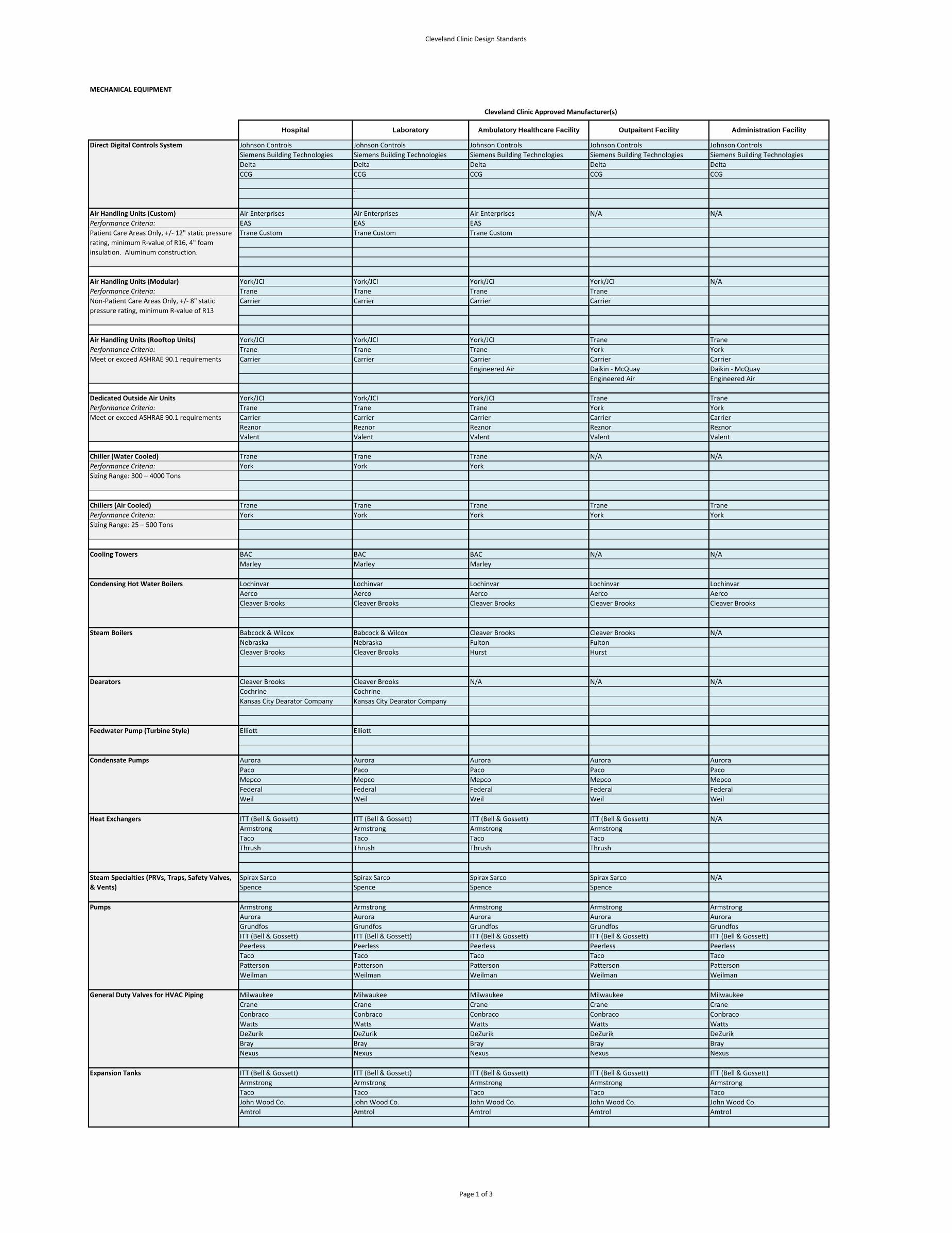
Cleveland Clinic Design Standards
MECHANICAL EQUIPMENT
Johnson Controls Johnson Controls Johnson Controls Johnson Controls Johnson Controls
Siemens Building Technologies Siemens Building Technologies Siemens Building Technologies Siemens Building Technologies Siemens Building Technologies
Delta Delta Delta Delta Delta
CCG CCG CCG CCG CCG
`
Air Handling Units (Custom) Air Enterprises Air Enterprises Air Enterprises N/A N/A
Performance Criteria: EAS EAS EAS
Trane Custom Trane Custom Trane Custom
Air Handling Units (Modular) York/JCI York/JCI York/JCI York/JCI N/A
Performance Criteria: Trane Trane Trane Trane
Carrier Carrier Carrier Carrier
Air Handling Units (Rooftop Units) York/JCI York/JCI York/JCI Trane Trane
Performance Criteria: Trane Trane Trane York York
Carrier Carrier Carrier Carrier Carrier
Engineered Air Daikin - McQuay Daikin - McQuay
Engineered Air Engineered Air
Dedicated Outside Air Units York/JCI York/JCI York/JCI Trane Trane
Performance Criteria: Trane Trane Trane York York
Carrier Carrier Carrier Carrier Carrier
Reznor Reznor Reznor Reznor Reznor
Valent Valent Valent Valent Valent
Chiller (Water Cooled) Trane Trane Trane N/A N/A
Performance Criteria: York York York
Chillers (Air Cooled) Trane Trane Trane Trane Trane
Performance Criteria: York York York York York
Cooling Towers BAC BAC BAC N/A N/A
Marley Marley Marley
Condensing Hot Water Boilers Lochinvar Lochinvar Lochinvar Lochinvar Lochinvar
Aerco Aerco Aerco Aerco Aerco
Cleaver Brooks Cleaver Brooks Cleaver Brooks Cleaver Brooks Cleaver Brooks
Steam Boilers Babcock & Wilcox Babcock & Wilcox Cleaver Brooks Cleaver Brooks N/A
Nebraska Nebraska Fulton Fulton
Cleaver Brooks Cleaver Brooks Hurst Hurst
Cleaver Brooks Cleaver Brooks N/A N/A N/A
Cochrine Cochrine
Kansas City Dearator Company Kansas City Dearator Company
Elliott Elliott
Aurora Aurora Aurora Aurora Aurora
Paco Paco Paco Paco Paco
Mepco Mepco Mepco Mepco Mepco
Federal Federal Federal Federal Federal
Weil Weil Weil Weil Weil
ITT (Bell & Gossett) ITT (Bell & Gossett) ITT (Bell & Gossett) ITT (Bell & Gossett) N/A
Armstrong Armstrong Armstrong Armstrong
Taco Taco Taco Taco
Thrush Thrush Thrush Thrush
Spirax Sarco Spirax Sarco Spirax Sarco Spirax Sarco N/A
Spence Spence Spence Spence
Pumps Armstrong Armstrong Armstrong Armstrong Armstrong
Aurora Aurora Aurora Aurora Aurora
Grundfos Grundfos Grundfos Grundfos Grundfos
ITT (Bell & Gossett) ITT (Bell & Gossett) ITT (Bell & Gossett) ITT (Bell & Gossett) ITT (Bell & Gossett)
Peerless Peerless Peerless Peerless Peerless
Taco Taco Taco Taco Taco
Patterson Patterson Patterson Patterson Patterson
Weilman Weilman Weilman Weilman Weilman
Milwaukee Milwaukee Milwaukee Milwaukee Milwaukee
Crane Crane Crane Crane Crane
Conbraco Conbraco Conbraco Conbraco Conbraco
Watts Watts Watts Watts Watts
DeZurik DeZurik DeZurik DeZurik DeZurik
Bray Bray Bray Bray Bray
Nexus Nexus Nexus Nexus Nexus
ITT (Bell & Gossett) ITT (Bell & Gossett) ITT (Bell & Gossett) ITT (Bell & Gossett) ITT (Bell & Gossett)
Armstrong Armstrong Armstrong Armstrong Armstrong
Taco Taco Taco Taco Taco
John Wood Co. John Wood Co. John Wood Co. John Wood Co. John Wood Co.
Amtrol Amtrol Amtrol Amtrol Amtrol
Meet or exceed ASHRAE 90.1 requirements
Sizing Range: 300 – 4000 Tons
Sizing Range: 25 – 500 Tons
Dearators
Steam Specialties (PRVs, Traps, Safety Valves,
& Vents)
Meet or exceed ASHRAE 90.1 requirements
Feedwater Pump (Turbine Style)
Condensate Pumps
Heat Exchangers
Expansion Tanks
General Duty Valves for HVAC Piping
Laboratory
Patient Care Areas Only, +/- 12" static pressure
rating, minimum R-value of R16, 4" foam
insulation. Aluminum construction.
Non-Patient Care Areas Only, +/- 8" static
pressure rating, minimum R-value of R13
Cleveland Clinic Approved Manufacturer(s)
Ambulatory Healthcare Facility Outpaitent Facility Administration FacilityHospital
Direct Digital Controls System
Page 1 of 3
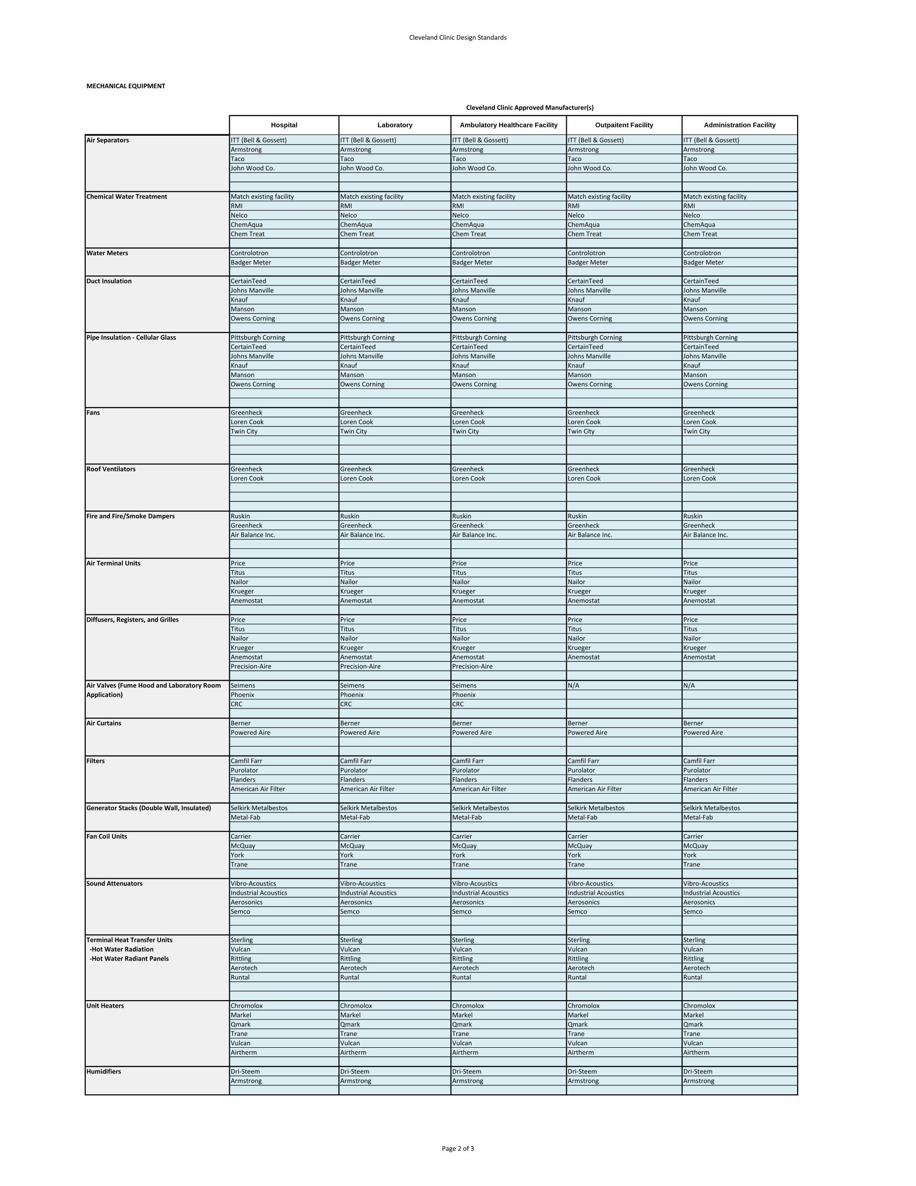
Cleveland Clinic Design Standards
MECHANICAL EQUIPMENT
Laboratory
Cleveland Clinic Approved Manufacturer(s)
Ambulatory Healthcare Facility Outpaitent Facility Administration FacilityHospital
Direct Digital Controls System ITT (Bell & Gossett) ITT (Bell & Gossett) ITT (Bell & Gossett) ITT (Bell & Gossett) ITT (Bell & Gossett)
Armstrong Armstrong Armstrong Armstrong Armstrong
Taco Taco Taco Taco Taco
John Wood Co. John Wood Co. John Wood Co. John Wood Co. John Wood Co.
Chemical Water Treatment Match existing facility Match existing facility Match existing facility Match existing facility Match existing facility
RMI RMI RMI RMI RMI
Nelco Nelco Nelco Nelco Nelco
ChemAqua ChemAqua ChemAqua ChemAqua ChemAqua
Chem Treat Chem Treat Chem Treat Chem Treat Chem Treat
Water Meters Controlotron Controlotron Controlotron Controlotron Controlotron
Badger Meter Badger Meter Badger Meter Badger Meter Badger Meter
CertainTeed CertainTeed CertainTeed CertainTeed CertainTeed
Johns Manville Johns Manville Johns Manville Johns Manville Johns Manville
Knauf Knauf Knauf Knauf Knauf
Manson Manson Manson Manson Manson
Owens Corning Owens Corning Owens Corning Owens Corning Owens Corning
Pipe Insulation - Cellular Glass Pittsburgh Corning Pittsburgh Corning Pittsburgh Corning Pittsburgh Corning Pittsburgh Corning
CertainTeed CertainTeed CertainTeed CertainTeed CertainTeed
Johns Manville Johns Manville Johns Manville Johns Manville Johns Manville
Knauf Knauf Knauf Knauf Knauf
Manson Manson Manson Manson Manson
Owens Corning Owens Corning Owens Corning Owens Corning Owens Corning
Greenheck Greenheck Greenheck Greenheck Greenheck
Loren Cook Loren Cook Loren Cook Loren Cook Loren Cook
Twin City Twin City Twin City Twin City Twin City
Greenheck Greenheck Greenheck Greenheck Greenheck
Loren Cook Loren Cook Loren Cook Loren Cook Loren Cook
Ruskin Ruskin Ruskin Ruskin Ruskin
Greenheck Greenheck Greenheck Greenheck Greenheck
Air Balance Inc. Air Balance Inc. Air Balance Inc. Air Balance Inc. Air Balance Inc.
Price Price Price Price Price
Titus Titus Titus Titus Titus
Nailor Nailor Nailor Nailor Nailor
Krueger Krueger Krueger Krueger Krueger
Anemostat Anemostat Anemostat Anemostat Anemostat
Price Price Price Price Price
Titus Titus Titus Titus Titus
Nailor Nailor Nailor Nailor Nailor
Krueger Krueger Krueger Krueger Krueger
Anemostat Anemostat Anemostat Anemostat Anemostat
Precision-Aire Precision-Aire Precision-Aire
Seimens Seimens Seimens N/A N/A
Phoenix Phoenix Phoenix
CRC CRC CRC
Berner Berner Berner Berner Berner
Powered Aire Powered Aire Powered Aire Powered Aire Powered Aire
Filters Camfil Farr Camfil Farr Camfil Farr Camfil Farr Camfil Farr
Purolator Purolator Purolator Purolator Purolator
Flanders Flanders Flanders Flanders Flanders
American Air Filter American Air Filter American Air Filter American Air Filter American Air Filter
Generator Stacks (Double Wall, Insulated) Selkirk Metalbestos Selkirk Metalbestos Selkirk Metalbestos Selkirk Metalbestos Selkirk Metalbestos
Metal-Fab Metal-Fab Metal-Fab Metal-Fab Metal-Fab
Fan Coil Units Carrier Carrier Carrier Carrier Carrier
McQuay McQuay McQuay McQuay McQuay
York York York York York
Trane Trane Trane Trane Trane
Sound Attenuators Vibro-Acoustics Vibro-Acoustics Vibro-Acoustics Vibro-Acoustics Vibro-Acoustics
Industrial Acoustics Industrial Acoustics Industrial Acoustics Industrial Acoustics Industrial Acoustics
Aerosonics Aerosonics Aerosonics Aerosonics Aerosonics
Semco Semco Semco Semco Semco
Sterling Sterling Sterling Sterling Sterling
Vulcan Vulcan Vulcan Vulcan Vulcan
Rittling Rittling Rittling Rittling Rittling
Aerotech Aerotech Aerotech Aerotech Aerotech
Runtal Runtal Runtal Runtal Runtal
Chromolox Chromolox Chromolox Chromolox Chromolox
Markel Markel Markel Markel Markel
Qmark Qmark Qmark Qmark Qmark
Trane Trane Trane Trane Trane
Vulcan Vulcan Vulcan Vulcan Vulcan
Airtherm Airtherm Airtherm Airtherm Airtherm
Humidifiers Dri-Steem Dri-Steem Dri-Steem Dri-Steem Dri-Steem
Armstrong Armstrong Armstrong Armstrong Armstrong
Terminal Heat Transfer Units
-Hot Water Radiation
-Hot Water Radiant Panels
Unit Heaters
Air Terminal Units
Diffusers, Registers, and Grilles
Air Valves (Fume Hood and Laboratory Room
Application)
Fire and Fire/Smoke Dampers
Air Curtains
Air Separators
Fans
Roof Ventilators
Duct Insulation
Page 2 of 3
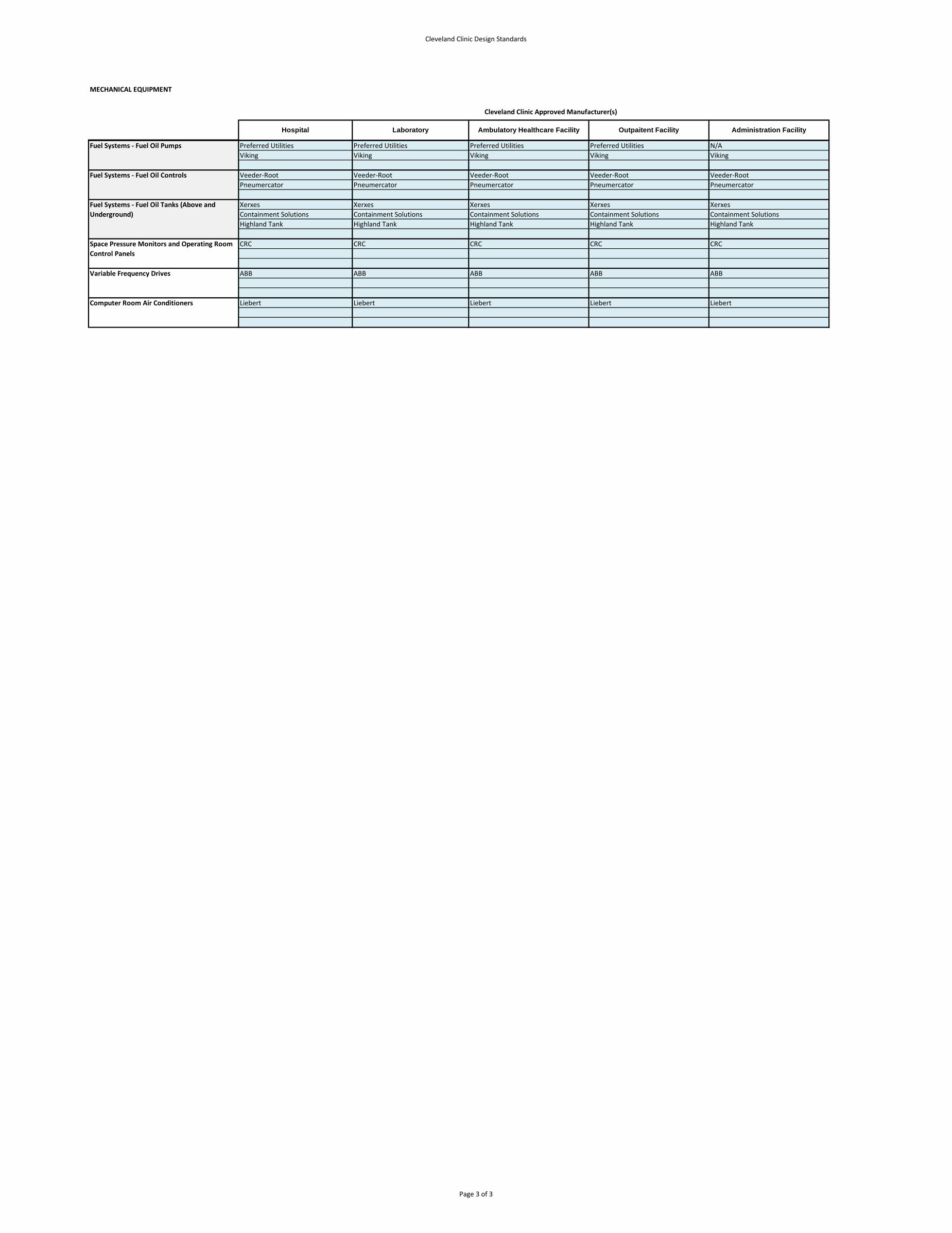
Cleveland Clinic Design Standards
MECHANICAL EQUIPMENT
Laboratory
Cleveland Clinic Approved Manufacturer(s)
Ambulatory Healthcare Facility Outpaitent Facility Administration FacilityHospital
Direct Digital Controls SystemFuel Systems - Fuel Oil Pumps Preferred Utilities Preferred Utilities Preferred Utilities Preferred Utilities N/A
Viking Viking Viking Viking Viking
Fuel Systems - Fuel Oil Controls Veeder-Root Veeder-Root Veeder-Root Veeder-Root Veeder-Root
Pneumercator Pneumercator Pneumercator Pneumercator Pneumercator
Xerxes Xerxes Xerxes Xerxes Xerxes
Containment Solutions Containment Solutions Containment Solutions Containment Solutions Containment Solutions
Highland Tank Highland Tank Highland Tank Highland Tank Highland Tank
CRC CRC CRC CRC CRC
ABB ABB ABB ABB ABB
Computer Room Air Conditioners Liebert Liebert Liebert Liebert Liebert
Space Pressure Monitors and Operating Room
Control Panels
Fuel Systems - Fuel Oil Tanks (Above and
Underground)
Variable Frequency Drives
Page 3 of 3