Design Guide to Underfloor Air Distribution - Guest Home Page
34
Design Guide to Underfloor Air Distribution 1
Transcript of Design Guide to Underfloor Air Distribution - Guest Home Page

Design Guide to Underfloor Air Distribution
1

Design Guide to Underfloor Air Distribution
INTRODUCTION The concept of underfloor air is not new, however changes in office space usage, sustainable design and indoor air quality issues have sparked considerable recent interest in the concept. Underfloor air conditioning had its start in computer rooms, at a time when mainframe computers generated considerable heat and had a considerable amount of complex cabling required by the computers. Access floor systems allowed plenty of open space to run cabling and a generous pathway to supply large quantities of cooling air under the intense heat of the electronics. The natural convection currents of warm air rising allowed cool air to enter low, cool the equipment and remove the warm air near the ceiling. Of course today’s computer rooms have changed and the need for this type of cooling has decreased. However, access floor systems have found new markets.
Reduced life cycle cost The recent interest in access floor systems has been spurred by other applications that can make use of the two principles that these earlier computer room systems addressed. First, the large open floor plenum was a convenient space to run large amounts of cable for power and communications. The greatest change in offices in the last 15 years has been an ever-growing need for voice, data and power connections to every worker’s workstation. This coupled with one other trend in office space design that is the use of more open plan space and a trend to move workers into cross-functional workgroups with great regularity. IFMA (International Facility Management Association) reported in one of their recent surveys that on average an office worker experiences a move every 5-½ months; this is 44 percent move rate. The term for these
types of office moves is often referred to as churn. The costs associated with these churn moves are one of the largest costs an owner / tenant may face. The costs associated with cabling moves and to a lesser extent HVAC system are the major portion of these move costs. So a system that could greatly simplify the costs associated with churn moves could help reduce total system life cycle cost. The advantage of access flooring is that cable and HVAC moves are greatly simplified.
Improved comfort The second feature of underfloor air distribution (UFAD) was that the same principle of warm air rising from hot electrical gear could also be applied to warm air around people. BOMA (Building Owners and Managers Association) reported in their “What Tenants Want Survey” that thermal and indoor air quality concerns were two of the top concerns and least met expectations of tenants. Traditional overhead air distribution systems are designed to do a very good job of mixing the air in the space and prevent stratification in the room. Without increased complexity and cost delivering thermal comfort to every occupant while also providing personal ventilation may be cost prohibitive. Overhead systems may require more fan energy to overcome static losses of generating the mixing, airflow patterns required within the space. Delivery of ventilation air requires sufficient mixing to assure that the ventilation component is delivered to the occupied breathing zone. By applying the warm air rising principle, air can be provided below the occupants and discharged directly into the breathing zone at relatively low velocity. The people warm the air and by natural
2

Design Guide to Underfloor Air Distribution
convection the air rises toward the ceiling. Since people only breath air in a zone from approximately the floor to 6 feet, the space above this zone can be treated as a stratified air layer and the load components in this zone treated differently. The result is that air provided underfloor can be supplied at low pressure and the energy for space conditioning can be reduced. The ventilation air can be provided in the zone where it is needed most with pollutants moved gently toward the return. Additionally, adjustable diffusers, which discharge air to small areas in the space, may be adjustable by the occupant and can result in an improvement in personal thermal comfort. This results in a system that can be more energy efficient,
comfortable, and provides better ventilation and improved indoor air quality. The application of an underfloor air distribution system requires the system designer to view the design very differently. It requires special consideration throughout the design process from design schematic stage, to load estimate, to commissioning. This document is intended to provide the designer with some of the guidelines to follow in systems design of underfloor air distribution, UFAD. Further in depth analysis of all aspects of UFAD design can be found in the ASHRAE UFAD Design Guide.
Figure 1 – Typical Underfloor Air Distribution System
3

Design Guide to Underfloor Air Distribution
UFAD System Benefits without special air-handling Several types of underfloor system designs exist. This manual covers a system offered by Carrier Corporation (see Fig. 3c). This approach employs standard air handling equipment and uses duct supply temperatures in the normal air conditioning range, which can best handle spot cooling requirements that often arise on every project. The air is distributed in the space through a pressurized plenum with swirl style floor grilles. The plenum is supplied through a zone parallel fan power box with a special DDC control to modulate temperature and controls plenum pressure. The primary damper provides the minimum ventilation air to the zone and maintains plenum pressure. The ECM style fan motor in the box modulates to mix return and primary air to maintain required temperature. Heating and cooling requirements for specialized high load spaces and perimeter zones are handled with conventional overhead systems, underfloor series fan boxes or fan coil units. APPLICATION CONSIDERATIONS Access flooring systems An access floor is a flooring system that is installed above the standard structural floor of the building. We will reference Haworth Access Flooring System in our discussions (see Fig 2). The systems consist of a matrix of adjustable pedestals mounted normally on two-foot centers, which support the weight of the access floor panels and the loads on the floor above. The two-by-two, approximately 1-1/8 inches thick concrete floor panels are laid into this grid system. The structural floor below is normally sealed to provide a moisture and dust barrier. The
primary usage of the flooring systems is to provide a service and utility space to run cabling for voice, data and power. As a result, the floors can be as little as 4 inches over the structural floor or they may be much higher. When the floor space is to be used as a supply plenum for air distribution, floor heights are normally at 12 to 18 inches high.
Figure 2 – Access Flooring System Access floor systems are successfully applied to many types of buildings both new construction and renovation. However, when applied to retrofit situations a few special considerations are required. Elevator lobbies and bathrooms which are built on the original structural floor need to be raised to the new floor elevation or ramps provided to get from the structural floor heights to the raised floor height. In new construction one architectural consideration of the floor systems is that a ceiling space could be reduced allowing a floor-to-floor height one foot less than standard. This can be accomplished by either the use of open ceiling space with only lighting and sprinklers in the space, or by reducing the ceiling plenum space since large supply ducts are not required. Then for every 12 stories of building an additional story could be added with minimal additional cost in the building shell cost. In buildings less than 12 stories the reduction
4

Design Guide to Underfloor Air Distribution
in height would result in a reduction of overall building shell cost.
Basic Concepts A traditional underfloor air distribution system uses the floor space between the structural floor and the access floor as a supply air plenum. There are three concepts normally associated with providing floor level cooling, each with distinctive characteristics:
1.) Displacement ventilation discharges air horizontally near the floor at very low velocities and near laminar flow conditions. The goal is to use only the buoyancy effects to create air motion within the space and maintain the stratification layer above the controlled zone that is not mixed. While this provides excellent ventilation effectiveness in the occupied zone it is not the optimum solution for thermal comfort. This is because of wide temperature variance, greater than the, ASHRAE (Std 55) accepted, 3 to 5 degree spread from head to toe.
2.) Under Floor Air Distribution
(UFAD) uses the same buoyancy principles as displacement however the air is discharged into the space with adequate velocity and air pattern to provide mixing only within the occupied zone. The system still tries to maintain the stagnant zone above the breathing zone. The system provides a more uniform temperature variation in the occupied zone to stay within the comfort envelope.
3.) The third concept is to provide airflow from underfloor that is controlled at the workstation. This method is called Task Ambient Conditioning. The control is normally accomplished with a small fan that directs an air jet at the occupant within the workstation.
We will use the UFAD approach in this manual. The plenum may be configured using one of two approaches. Either the entire underfloor plenum is pressurized to a relative low pressure of approximately 0.10 inch WG or air is discharged into the plenum at zero or neutral pressure and fans near the outlets draw the supply air from the plenum and discharge it to the space. Neutral pressure plenums have a reduction in leakage around floor tiles and plenum penetrations, but fan wiring and energy costs negate some of the system’s inherent benefits. The use of the underfloor plenum has two major impacts on system design. First, since the air is brought in at floor level, a chance exits for a cold floor or for cold discharge temperatures near the occupant’s feet. Both conditions are objectionable so the air must be provided at a much warmer temperature than normal air conditioning levels. The accepted level is between 61 F to 65F. This impacts equipment selection and operation, and impacts air distribution devices. The second issue is that the large surface area and mass of the structural slab provide both a thermal mass that shifts load patterns and creates significant amounts of thermal decay to diffusers located far from the point at which supply air enters the plenum. Conditioned air is handled in one of two methods. The first method is when the space return air is removed near the ceiling and the entire volume returned to the air-handler.
5

Design Guide to Underfloor Air Distribution
This method requires special treatment by the air-handler to bypass the required air and condition the required supply amount without losing control of temperature and particularly humidity in the space (see fig.3b). The second approach is to use a mixing box located near the space that draws a portion of the return air near the ceiling and mixes it with the supply air to maintain the floor plenum pressure and temperature. The Carrier system discussed here uses the second method (fig.3c). Perimeter zones and spaces such as conference rooms present some interesting challenges. These spaces have loads which vary greatly with time and which may have air requirements that cannot be handled by 65-degree air. To provide for these spot cooling situations either a fan powered box is provided under the floor to increase airflow or a separate unit that can use standard 55-degree air can be used. A fan coil unit located under the floor can also be used to provide for the cooling and heating needs. When 55-degree air is supplied to zone mixing units, the system may also employ traditional methods used with overhead air distribution, to meet high load requirements. Heating along the perimeter also presents challenges for UFAD systems. To provide the necessary heat, terminal units are frequently provided to addresses this situation. One very common method is to use a fan coil unit that may be placed under the floor and near the perimeter. The fan coil contains a heating coil, electric or hot water and it is controlled to overcome transmission losses.
Figure 3 – Basic System Design Options
3a. Conventional Overhead Distribution
84°F Return to AHU 55°F Supply from AHU
3c.
75°F
UFAD with Zone Mixing Unit
75°F
84°F
62°F
78°F Return to AHU
55°F Supply from AHU
78°F
75°F 75°F
3b.
62°F
84°F Return to AHU
62°F Supply to AHU
UFAD with Full Return
75°F 75°F
84°F RETURN RETURN
84°F
62°F
6

Design Guide to Underfloor Air Distribution
Product Overview Floor plenum - The space between the access floor and the structural floor is the floor plenum. Using this space as an air distribution plenum requires some special considerations. First the floor panel seams must provide a tight seal to prevent air leakage from the plenum into the space. In some cases ductwork is run through the space to special variable load areas and the space may need partitioning for life safety or thermal zoning. A typical underfloor plenum is between 12 and 18 inches in height. Diffusers – Room air distribution is accomplished through one of two types of floor diffusers. Interior spaces are controlled through a system of adjustable passive floor mounted diffusers. Each diffuser consists of an adjustable swirl plate located in a mounting basket and mounts through a hole cut in the concrete floor panel. The basket catches any dirt or spilled liquids and prevents contamination of the space below the floor. The adjustable swirl plate allows the occupants to adjust their diffusers to a comfortable level in their space. The diffusers are design to achieve mixing of the approximately 65 F degree supply air within a very tight radius of the diffuser and at very low velocity. Typical diffuser airflow is about 60 to 100 CFM per diffuser.
A second type of diffuser is used with underfloor mixing boxes and perimeter fan coil units. This rectangular grille is used to provide an air curtain washing exterior surfaces with warm or cold air. These grilles depend on much higher velocities and can be used in various lengths to match the airflow requirements of the mixing box or fan coil unit. Either a 0° or 15° deflection blade can be used to provide the required throw pattern. A version of the rectangular grilles can also be installed in a plenum that has a control damper to provide variable volume control to selected spaces. The rectangular grilles can also be used to allow return air from above the floor back down to the underfloor mixing boxes if desired. If used directly in the pressurized plenum, a standard balancing damper can be added to adjust airflow.
Figure 5 Rectangular grille w/ plenum – Model 35BF-D
Figure 4 Swirl Plate Style – Model 35BF-R
7
Design Guide to Underfloor Air Distribution
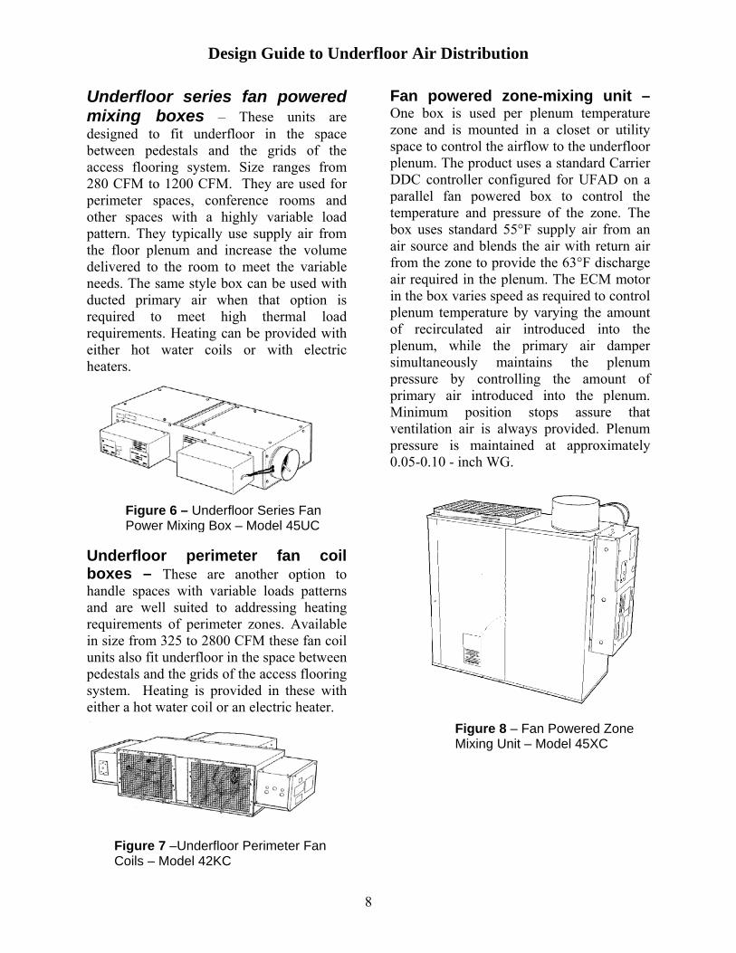
Underfloor series fan powered mixing boxes – These units are designed to fit underfloor in the space between pedestals and the grids of the access flooring system. Size ranges from 280 CFM to 1200 CFM. They are used for perimeter spaces, conference rooms and other spaces with a highly variable load pattern. They typically use supply air from the floor plenum and increase the volume delivered to the room to meet the variable needs. The same style box can be used with ducted primary air when that option is required to meet high thermal load requirements. Heating can be provided with either hot water coils or with electric heaters.
Underfloor perimeter fan coil boxes – These are another option to handle spaces with variable loads patterns and are well suited to addressing heating requirements of perimeter zones. Available in size from 325 to 2800 CFM these fan coil units also fit underfloor in the space between pedestals and the grids of the access flooring system. Heating is provided in these with either a hot water coil or an electric heater.
Fan powered zone-mixing unit – One box is used per plenum temperature zone and is mounted in a closet or utility space to control the airflow to the underfloor plenum. The product uses a standard Carrier DDC controller configured for UFAD on a parallel fan powered box to control the temperature and pressure of the zone. The box uses standard 55°F supply air from an air source and blends the air with return air from the zone to provide the 63°F discharge air required in the plenum. The ECM motor in the box varies speed as required to control plenum temperature by varying the amount of recirculated air introduced into the plenum, while the primary air damper simultaneously maintains the plenum pressure by controlling the amount of primary air introduced into the plenum. Minimum position stops assure that ventilation air is always provided. Plenum pressure is maintained at approximately 0.05-0.10 - inch WG.
Figure 6 – Underfloor Series Fan Power Mixing Box – Model 45UC
Figure 8 – Fan Powered Zone Mixing Unit – Model 45XC
Figure 7 –Underfloor Perimeter Fan Coils – Model 42KC
8

Design Guide to Underfloor Air Distribution
Central equipment – Since this system uses a zone mixing concept and air is supplied at normal unit design conditions, special air-handling equipment is not required. Mixing boxes may be used with air-handlers in chilled water or DX type systems or with many types of packaged VAV equipment as well. Careful psychrometric analysis should be made of coil entering conditions to be sure the coil will meet the required leaving air conditions particular to what may be higher than normal entering sensible heat factors. Part load operating conditions in terms of coil control or staging should be evaluated to be sure room humidity levels can be maintained below 60% RH. Economizers should be used with all system types where local climate permits and should use an integrated differential enthalpy type control. Because of low static pressure requirements, fan sizes may be lower than conventional overhead systems. Due to varying air volumes to the zones, the use of VFD’s is recommended, which will also improve system efficiency. The use of high-quality filtration is recommend since a prime consideration of the UFAD system is good indoor air quality.
Types of Buildings Underfloor air systems are not the answer to every building but may represent significant life cycle cost savings when applied to the appropriate buildings. The solution is most often related to three different types of applications. First, UFAD can be applied in new construction office space where frequent office changes are anticipated. Owners can benefit from the reduced costs of moving offices particularly as related to the cost of communications cable and wiring. In general small spaces within a building are not well suited to underfloor air systems. Nor does UFAD make good sense in a building with very
high perimeter to interior ratios or buildings with many spaces, which have highly variable loads. Normally, the best applications in new construction spaces are offices with open plan construction. UFAD may also be used successfully in other types of space with mostly internal loads and open plan construction, as is done in some schools spaces. The second application is in retrofit situations where the building characteristics make overhead air distribution systems difficult to apply. Recent trends to rehabilitate old warehouse space into offices and downtown revitalization of existing structures may fall into this category. The issues with elevator and plumbing fixture connections must be addressed. However, the savings and ease of providing the cabling services and air distribution under the floor may well pay for the cost of access flooring. The benefits of improved thermal comfort and indoor air quality may make the space even more attractive to tenants. A third area where underfloor distribution may make sense is in buildings with very high ceilings and no place to run overhead air distribution. Some places of assembly (meeting rooms, churches, auditoriums) fit into this category. Again, open plan and internal load concentration are the keys to successful applications.
System benefits and cautions (+) Thermal comfort – Since UFAD
systems allow the occupant a degree of control over ones own individual climate through adjustment of the diffuser; there is a higher degree of perceived comfort. Air distribution diffusers have also been shown to provide good head to toe temperature variations without disrupting the benefits of a stratification zone.
9
Design Guide to Underfloor Air Distribution
(+) Ventilation effectiveness – Fresh
air supply is introduced to the space low to the floor. As the air warms the air rises and pollutants are carried toward the ceiling by the warm air. Rather than mixing the air within the entire space, fresh air is provided to the breathing zone. The effect of this ventilation method may actually result in efficiencies greater than 100%, but has not yet been documented. ASHRAE Standard 62, (Table 6.2) lists the ventilation efficiency of UFAD systems at 100%. The perceived indoor air quality is better and may potentially be used to reduce total ventilation airflow, although this is not generally recommended.
(+) Energy usage – UFAD systems
may have significant energy savings when compared to overhead air systems because of lower fan static requirements. Economizer hours of operation may increase energy savings as well, but is highly dependent on the local climate.
(+) Reduced Life Cycle Costs –
Based on the reduction in costs
associated with office churn, UFAD systems may have better total life cycle costs. In addition, this energy efficient design will also increase the life cycle cost benefit and may make the system look more appealing.
(+) Reduced Floor-to-Floor Height – The ability to reduce the floor-to-floor height by up to one foot per floor can result in additional floor space or reduced shell construction cost. The reduction comes from reducing or eliminating ceiling plenums. However, this reduction must be evaluated based on the need for ceilings to hide light fixtures, piping for sprinklers, and to help improve room acoustics.
(+) Improved productivity and
health – It is often a controversial thing to prove but recent studies have shown that productivity can be improved through good indoor air quality and comfort. Since the costs associated with employees far out weigh all other operating costs, savings can be significant.
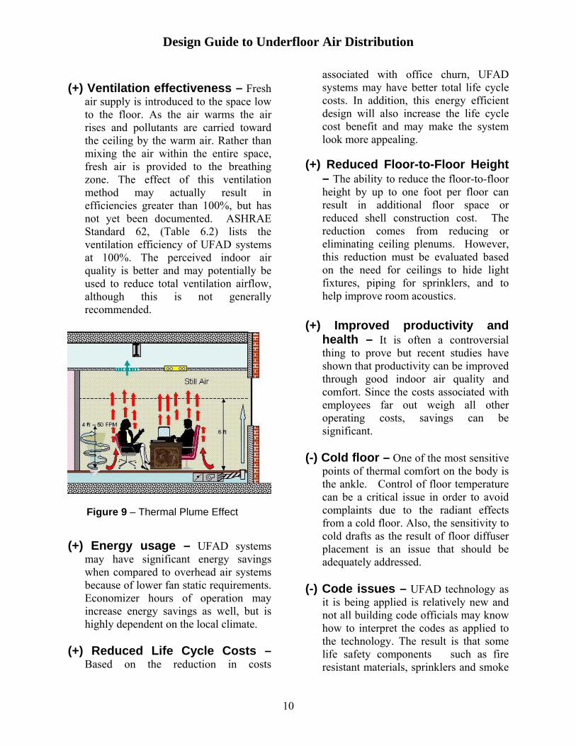
(-) Cold floor – One of the most sensitive
points of thermal comfort on the body is the ankle. Control of floor temperature can be a critical issue in order to avoid complaints due to the radiant effects from a cold floor. Also, the sensitivity to cold drafts as the result of floor diffuser placement is an issue that should be adequately addressed.
Figure 9 – Thermal Plume Effect
(-) Code issues – UFAD technology as
it is being applied is relatively new and not all building code officials may know how to interpret the codes as applied to the technology. The result is that some life safety components such as fire resistant materials, sprinklers and smoke
10

Design Guide to Underfloor Air Distribution
detectors may be required on certain projects.
(-) Condensation – Even though the
thermal mass effects of the plenum floor slabs can have a positive effect on sensible load swings, care needs to be exercised with control schemes that pre-cool the slab and then are allowed to bring in large quantities of potentially moist outdoor air. Air supplied to the underfloor plenum must be kept above the dewpoint temperature of the floor slab.
(-) Humidity control – The impact of
local climate and part load control methodologies must be carefully evaluated. The impact of higher supply air temperatures has the potential to negate some of the central system’s natural latent heat removal capability. Design analysis should evaluate the effects of part load latent control and control methodology to make sure room relative humidity is kept below 60%.
Sustainability (LEED™ points) There is a nationwide trend toward constructing buildings that are more environmentally friendly to meet green building or sustainable design construction standards. The best known green building standard is the LEED-NC™ standard issued by the U.S. Green Building council, but additional standards like the LEED-CI for interior systems is also being prototyped. The LEED (Leadership in Energy and Environmental Design) standards are a voluntary rating system that rates the building design on its environmental impact on the community, the site, the water efficiency, the energy efficiency and the indoor environmental quality for the occupants.
This standard sets green building objectives in 5 categories that offer a total of 32 credits, from which a design can accumulate up to 69 points. The rating system is based on the number of points awarded and goes from a certified level at 29 to platinum level at 52. Some prerequisite requirements are required, but other than that, the points may come from any of the 5 categories. HVAC related systems account for 40% of the possible points. The points are based on the entire building as a system. No particular product or system is certified by the program but rather the building in which they are used. Underfloor air systems have potential in at least seven areas, primarily within the environmental and indoor air quality areas. The largest points area in the program is optimizing energy performance. This credit varies from 1 point for exceeding ASHRAE 90.1 energy cost budget (ECB) model by 15%, up to 10 points for a 60% reduction. In most UFAD projects the analysis would involve using the ASHRAE energy cost budget to compare the underfloor system to the energy costs of a VAV reheat system. UFAD systems may have a distinct advantage in this area since they incorporate many potential energy saving features. Lower fan static requirements as the result of low plenum pressure distribution will reduce required fan energy. Mechanical cooling requirements and hence equipment size and part load efficiency may be improved due to the use of higher discharge temperatures. Economizer usage may be extended to get more free cooling hours and help reduce part load energy requirements. In general, UFAD systems have the potential to show significant energy savings over the required base system used in the energy budget model.
11

Design Guide to Underfloor Air Distribution
The UFAD system may also qualify for points under the material and resources category. Within this category 3 points can be earned for building reuse. If the project involves an existing building, the percentage of building shell reuse would help obtain these credits. UFAD systems lend themselves very well to certain retrofit situations where the building is being renovated to meet the requirements of new technology without destroying the current building structure. UFAD gives the architect a range of options to achieve these goals. Then, depending on the location, it is possible that the floor system used would qualify for the regional credit if the project were within 200 or 500 miles of the equipment manufacturing location. Looking at the Indoor Environmental Quality category, UFAD systems have the potential to qualify for points in 3 areas. This is the area where many of the existing certified projects have relied on points from UFAD systems. The first is the area of ventilation effectiveness. UFAD systems are not rated by ASHRAE as having any advantage in ventilation effectiveness as we noted earlier. However, in the current LEED documentation, it is implied to have ventilation effectiveness greater than one. As a result, the use of UFAD systems may be a qualifying point. The second area addresses system controllability, where the LEED requirement is for interior zones to provide individual control to at least 50% of the occupants. Since UFAD diffuser provides individual control inherently, the system again is nearly an automatic qualification for this point. The third area relates to thermal comfort. Since UFAD systems have been shown to provide a high degree of personal comfort with space control parameters that fall within the guidelines of the ASHRAE standard 55
comfort envelope, the system can qualify for this credit as well. UFAD has shown itself to be an excellent system to consider on projects seeking LEED certification. Remember, however, that certification is based on the total building system and the points and overall rating for a specific project are dependent on the design of that project.
12

Design Guide to Underfloor Air Distribution
DESIGN PROCESS Design Decisions When beginning the design of a UFAD system certain key differences and concepts need to be remembered to avoid incorporating elements of traditional overhead mixing systems:
• Underfloor systems work best when a stratification layer is established at 6 feet above the access floor. This creates a partial displacement ventilation effect within the room and improves ventilation effectiveness, contaminant control, heat capture, and reduces loads within the space, transferring them directly to the return air.
• Airflows need to be closely matched to the loads within the occupied zone so as not to over air the space, losing the partial displacement ventilation effect.
• Mixing only occurs within the occupied zone and happens so efficiently that it is normal for a 3 to 5º F temperature gradient to occur, right at the ASHRAE 55 comfort standard limit.
Do not include excess safety factors; it will lead to over airing the zone spaces, resulting in many occupant comfort complaints and loss of the stratification layer.
Zoning Decisions Because of the underfloor air supply plenum aspects of a UFAD system, zoning decisions have a few complexities:
• Thermal decay, the increase in cooling supply air temperature due to heat transfer to the floor slab and access flooring, limits the zone maximum travel distance from the terminal discharge into the plenum to the furthest diffuser to 50-60 feet.
So for a typical side-fed core location the maximum zone size would be 120 ft by 60 ft, or 7200 ft2 or less.
• Open office interior zones, those that have fairly uniform loading, lend themselves to pressurized plenums using passive swirl diffusers.
• Open area zones with loading differences are hard to “isolate” from one another without plenum barriers beneath the access floor. Too many barriers destroy the future ease of rezoning and utility access to points of use.
• Zones with high heating loads need to consider the use of ducted linear bar diffusers that deliver the conditioned air to the load point (usually exterior walls with glazing) without significant thermal decay. Insulate ductwork to prevent loss of cooling capacity.
• Perimeter zone size may be restricted by ASHRAE 90.1, requirements for exposure zoning, which limits linear wall per exposure to 50 feet.
• Locating zone-mixing terminals in vertical equipment closets does take up more useable floor space compared to locating the units within the underfloor plenum, but is a good choice for reasons of ease of maintenance and minimizing obstructions within the plenum.
• When high cooling or dehumidification loads are present, such as conference rooms and rooms with plants, process or large equipment or solar loads, consider conditioning these spaces with traditional VAV terminals using lower temperature (50 to 55ºF) primary air. This hybrid system design will result in smaller central
13

Design Guide to Underfloor Air Distribution
equipment, as well as ductwork mains and branches.
General Layout When beginning the layout of a UFAD system it is best to think of it as an upside down conventional overhead system, with the following similarities and differences:
• Central cooling and heating equipment, as well as ductwork mains and branches to zone mixing terminals, can be nearly identical to traditional overhead systems. Systems that do not employ the use of zone mixing terminals require special consideration based on the volume and temperature from the air-handling source.
s. Systems that do not employ the use of zone mixing terminals require special consideration based on the volume and temperature from the air-handling source.
• Zoning occurs in much the same way as with other systems, but due to the duct mains above and zoned distribution plenum below, there is a need for multiple vertical duct drops
and equipment chases strategically located around the floor plate.
• Zoning occurs in much the same way as with other systems, but due to the duct mains above and zoned distribution plenum below, there is a need for multiple vertical duct drops
and equipment chases strategically located around the floor plate.
• When using zone fan powered mixing boxes (FPMB) above the access floor the chases must provide adequate room to locate the terminal as well as provide required service clearances.
• When using zone fan powered mixing boxes (FPMB) above the access floor the chases must provide adequate room to locate the terminal as well as provide required service clearances.
• UFAD systems use diffusers in the access floor, much closer to the occupants, so special care needs to be exercised in their layout. Since it is a non-ducted system, simply swapping floor panels can make relocations easy.
• UFAD systems use diffusers in the access floor, much closer to the occupants, so special care needs to be exercised in their layout. Since it is a non-ducted system, simply swapping floor panels can make relocations easy.
• UFAD systems work best with uniformly loaded thermal areas. In high-load and variable-loaded zones, UFAD can be used in conjunction with traditional overhead systems. This creates an overall hybrid system that utilizes the best features of both types of systems (figure 10b).
• UFAD systems work best with uniformly loaded thermal areas. In high-load and variable-loaded zones, UFAD can be used in conjunction with traditional overhead systems. This creates an overall hybrid system that utilizes the best features of both types of systems (figure 10b).
Figure 10a - UFAD with Zone Mixing Box Figure 10a - UFAD with Zone Mixing Box
RETU RETURN
55° SA from Air Source
75°F
62°F
84°F
Underfloor Fan Coil or Fan Powered mixing Box
75°F
84°F
Zone Parallel Fan Powered mixing Box
Passive Floor Diffusers
84° RA to Air Source Figure 10 – Carrier UFAD Design Solutions
14

Design Guide to Underfloor Air Distribution
15
UFAD Hybrid System
RETUR RETUR
84° F Return to Air Source
55° F Supply from Air Source
75°F
62°F
84 ° F
75°F
Zone Parallel Fan Powered mixing Box
Passive Floor Diffusers Underfloor Fan Coil or Series Fan Powered Mixing Box
VAV Moduline Terminal
84 ° F
Figure 10b - UFAD Hybrid System

Design Guide to Underfloor Air Distribution
Building Load Considerations
NEED FOR TWO ZONES - With an effective stratification layer, running cooling and heating zone loads for use with a UFAD system is complex. The claim that loads that occur in the upper stratified zone do not affect the occupied zone have been observed in tests and completed projects, but to date, no computerized load estimating program is capable of modeling this condition. Using recent project experience, and not being conservative in assigning loads or safety factors to the occupied space can reduce space cfm requirements with a UFAD system.
LOAD ESTIMATING CONCEPTS & FACTORS - Manual output adjustment of computer program inputs and outputs allow designers to more closely model UFAD systems and correctly assign loads and set zone airflows.
• For stratification to benefit cooling loads, floor diffuser 50 fpm throw cannot exceed 4 to 5 feet, so as not to affect the stratification height, which is typically 6 feet.
• Lighting energy is predominantly radiant; so only assign 1/3rd of total watts directly to the stratified zone. When return air is taken through the light troffers, a greater portion of the total watts used, up to 50 percent, can be assigned to the stratified zone.
• Exterior wall conductive load is still transferred into the zone as predominantly radiant (often over 60 percent), so only 1/3rd of the upper wall area load should be assigned to the stratified zone.
• Alternatively, lowering the zone ceiling height to the midpoint value of the stratified zone would allow most computerized load programs to automatically assign the loads addressed above to the return air.
• Solar loading through glazing is 100 percent radiant, unless internal shading is used. Since manually adjusted shades cannot be counted on when sizing equipment or setting airflows, do not assign any direct solar load to the stratified zone.
• Solar wall loading becomes over 1/3rd convective, so an appreciable portion of this amount can be manually assigned to the upper stratified zone, especially if wall-washing linear bar supply registers and overhead perimeter returns are used in the room air distribution design.
Figure 11 – UFAD Design Load Concepts
• People loads should always remain 100 percent assigned to the occupied zone.
• Equipment loading should not be assigned to the stratified zone unless return register placement near the equipment is used to capture a portion of the load with the return air, or it is believed that aggressive thermal plumes will develop and
16

Design Guide to Underfloor Air Distribution
carry a substantial portion of the load into the stratification zone.
• Infiltration loads always remain within the occupied zone, and outdoor air ventilation loads always remain a part of the central equipment coil loading.
When the load estimates have been run with appropriate UFAD adjustments made, two loads should be compiled by the designer, QOCCUPIED for the lower mixed zone, and QUNOCCUPIED for the stratified zone above the stratification height. With these loads the designer can then calculate the following system design parameters:
1. First, solve for airflow in the occupied zone. This is the supply air delivered by the underfloor diffusers (the zone mixing box total airflow).
Equation 1 Where:
TRoom is the thermostat set point for the space, and TPlenum Supply is assumed discharge air temperature in the plenum
2. Solve for CFM primary air required.
(This is the air supply from the air handler and used in zone box selection)
Equation 2
T Room is the thermostat set point for the space, and
T AHU Supply is the assumed primary air temperature into the zone-mixing box.
3. Finally, solve for TReturn from the
stratified zone. This is the return air temperature to the zone mixing box, and the air handler before outdoor air mixing occurs.
Equation 3 Where: TRoom is the thermostat set point for the space, and CFMRoom is the airflow required in the occupied zone.
DON’T OVER AIR THE ZONE - When working with Equation 1, the space set point temperature, TRoom, can be raised up closer to the temperature at the stratification height (approximately 75 F) to more accurately determine the actual minimum airflow required to meet the occupied zone load. Similarly, in Equation 3, TRoom should use the same higher value, remembering that with UFAD systems and the partial displacement ventilation effect, return air temperatures are quite a bit higher than the space set point temperature. Other load-related concerns come from air leakage out of the plenum through construction gaps, leaks between the floor tiles directly cooling the occupied zone, and radiant and convection cooling by the cooler floor panels and structural sub-floor. The last two lower the room CFM, and if not accounted for, will lead to undesirable zone over airing and increased “too cold” complaints from the occupants in the space.
CFM room = Qoccupied / (1.10 * (Troom – T plenum supply))
CFMZone-Box = Qoccupied / (1.10 * (Troom – T AHU supply))
TReturn = (Qunoccupied /1.10 * CFMroom)+ Troom
17
Design Guide to Underfloor Air Distribution
Central Equipment Selection While a UFAD system is thought of as a predominantly air distribution design variation, there are many particulars affecting central equipment selection that the designer needs to pay attention to, particularly:
• Central fan energy should be less than a traditional system because of the low plenum pressure and substantial reduction in ductwork downstream from the air terminal.
• Primary cooling air quantities can be reduced when potential load credits are realized from the stratification zone partial displacement ventilation effect.
• The entering coil psychrometrics should be checked to be sure that the cooling coil selected would be able to achieve the required Apparatus Dew Point (ADP) and bypass factor. In some cases this may require the use of larger coils, more coil rows or lower face velocities.
• Part load loss of humidity control can be a significant issue. A part load analysis should be done to determine if the coil control methodology being used or the refrigeration staging will provide sufficient latent heat removal at part load operation.
• Air economizers should be used whenever possible based on the local climate. The use of an enthalpy wheel is recommended for periods when the 55° F supply air temperature off the coil is not required. Use care in setting up the economizer changeover temperature to ensure that the 60° F maximum space dewpoint temperature will not be exceeded.
Traditional cooling coil leaving air temperatures of 50 to 55º F should be used for the coil selection in climates requiring
dehumidification of outdoor air. Bypassing return air around the cooling coil is one method of obtaining the required 61 to 65º F supply air temperature to the underfloor plenum. This can be done in the mechanical equipment room, but is also effective by blending in the return air off the suspended ceiling return plenum using Parallel Fan Power Mixing Boxes (PFPMB).
Fan Static Requirements Reduced external static pressure on the central equipment is an advantage of a UFAD system. Supply ductwork runs and air pressure drops on the zone terminals leading to the plenums are similar to conventional systems. The same is the case with return ducts, but there is always less than 0.10 in. wg pressure requirement on the underfloor plenum and diffusers downstream from the zone mixing terminals. While this savings of 0.25 to 0.50 in. wg appears small, add to it the overall reduction in primary airflow associated with UFAD’s partial displacement effect, we should see real reductions in system fan motor horsepower.
Terminal Equipment Selection
Room Air Distribution OCCUPIED ZONE DELIVERY When a UFAD system is used, room air distribution occurs within the occupied zone (up to 6 feet above finished floor), making this area a critical design element. Designs can be either CAV (constant air volume) or VAV (variable air volume), or as is more often the case, a hybrid using some of both to satisfy the varying room requirements. CAV systems usually vary the temperature of the supply air to meet the space temperature set point, while VAV systems provide constant temperature and vary the
18
Design Guide to Underfloor Air Distribution
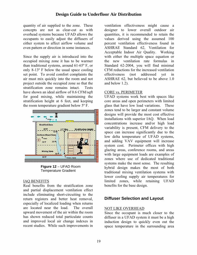
quantity of air supplied to the zone. These concepts are not as clear-cut as with overhead systems because UFAD allows the occupants to easily adjust the diffusers of either system to affect airflow volume and even pattern or direction in some instances. Since the supply air is introduced into the occupied mixing zone it has to be warmer than traditional systems, around 61-65º F, or only 8-13º F below the usual space cooling set point. To avoid comfort complaints the air must mix quickly into the room and not project outside the occupied zone so that the stratification zone remains intact. Tests have shown an ideal airflow of 0.6 CFM/sqft for good mixing, while maintaining the stratification height at 6 feet, and keeping the room temperature gradient below 5º F.
IAQ BENEFITS Real benefits from the stratification zone and partial displacement ventilation effect include eliminating short-circuiting to the return registers and better heat removal, especially of localized loading when returns are located near the load. The overall upward movement of the air within the room has shown reduced total particulate counts and improved local air change indexes in recent studies. While such improvements in
ventilation effectiveness might cause a designer to lower overall outdoor air quantities, it is recommended to retain the values derived using the assumed 100 percent ventilation effectiveness found in ASHRAE Standard 62, Ventilation for Acceptable Indoor Air Quality. Working with either the multiple space equation or the new ventilation rate formulas in Standard 62-2004, you will find minimal CFM reductions for the increased ventilation effectiveness (not addressed yet in ASHRAE 62, but believed to be above 1.0 and below 1.2). CORE vs. PERIMETER UFAD systems work best with spaces like core areas and open perimeters with limited glass that have low load variations. These zones tend to be larger and constant volume designs will provide the most cost effective installations with superior IAQ. When load concentrations increase and/or high load variability is present, CFM delivery to the space can increase significantly due to the low delta temperature of UFAD systems, and adding VAV equipment will increase system cost. Perimeter offices with high glazing areas, conference rooms, and areas with large equipment loads are examples of zones where use of dedicated traditional systems make the most sense. The resulting hybrid design makes the most of both traditional mixing ventilation systems with lower cooling supply air temperatures for limited zones, while retaining UFAD benefits for the base design.
Figure 12 – UFAD Room Temperature Gradient
Diffuser Selection and Layout NOT LIKE OVERHEAD Since the occupant is much closer to the diffuser in a UFAD system it must be a high induction design to quickly even out the space temperature in the surrounding area
19

Design Guide to Underfloor Air Distribution
and avoid drafts and occupant comfort complaints. The higher supply air temperature of a UFAD system and the need for quick mixing results in greater numbers of diffusers located in the access floor. Since the diffusers have low pressure drops and plenum pressure is very uniform, UFAD designs can be considered self-balancing at the diffuser. APPLYING DIFFERENT TYPES AND STYLES There are two basic types of diffusers to choose from: passive and active. Passive are used in pressurized plenum systems and active diffusers are used in neutral pressure or fan-assisted pressurized plenum systems. There are three basic styles of diffusers, swirl, VAV floor grille and linear bar grille. Passive styles are able to move required air quantities at low plenum pressures (0.05 to 0.10 in. wg) and have very low noise generation values, usually under NC20. In fact, a white noise generation system within the plenum is often recommended for proper acoustic privacy in open office situations. The table below summarizes the various features and application recommendations for these products. Use of other products, such as task/ambient conditioning (TAC) and personal environmental modules (PEM), are not covered in this guide, but
comprehensive information is available to learn more about these UFAD refinements. Passive type diffusers can be easily rearranged by just moving floor panels; active types require moving fan units, power and control wiring and potentially ductwork. Active diffusers are found more often in TAC/PEM designs and as part of hybrid solutions to satisfy heavy and/or widely variable loaded spaces. UFAD diffusers should not be used where liquid spillage potential is high, even though they have a catch basin for incidental spills, and they should not be placed in traffic areas where high rolling loads are expected. To select a passive diffuser, determine the required room airflow with Equation 1 and divide it by the tabulated airflow for the diffuser at the pressure maintained in the plenum. This will be the approximate number of diffusers required. Adjustments may be made to be sure all spaces receive adequate coverage.
#Diffusers = CFMRoom/Diffuser CFMat Plenum Pressure
Equation 4
Cooling Terminal Selection
Each zone (thermostat) will require a dedicated air terminal to satisfy cooling and heating airflows to the areas covered by the zone. Larger, more uniformly loaded open office interior zones can be supplied by parallel fan-powered mixing boxes (PFPMB) all the way up to 3,700 CFM primary airflow (5,800 CFM mixed airflow). Smaller perimeter zones and partitioned interior zones can be handled with the same equipment down to 500 CFM primary airflow.
DIFFUSER TYPE
DIFFUSER STYLE
UNIFORM LOADING
VARIABLE LOADING
Swirl
Core – open areas & offices Perimeter – open areas
Base loading
Passive
Floor grilles
Large equip. loads, few people
Base loading
Swirl Not recommended
Not recommended
Active (fan-forced)
Linear Bar or Floor grilles
Spaces with tighter temperature tolerances
Conference Rooms Perimeter, Htg & Clg
20

Design Guide to Underfloor Air Distribution
Once cooling loads have been completed, basic terminal selection can occur, using traditional manual or software methods. Keep the following items in mind when selecting units for UFAD systems:
• Primary airflow can come from a traditional temperature source (50 to 55º F +) or even from a low-temperature central system, keeping supply ductwork mains and branches small.
• Primary airflow is the airflow determined with equation 2 and is based on the air handler supply air temperature. Total airflow is the amount calculated by equation 1 above.
• Care must be exercised in the selection of the zone mixing unit to be sure it will provide the total mixed airflow based on calculated entering conditions to the zone mixing unit. The use of selection software is recommended.
• Since the units are closer to the occupied space, often mounted vertically within an equipment closet, care needs to be taken so that acoustic values are acceptable, by keeping inlet duct pressures down, selecting units in the low end of their range, and using the appropriate acoustic attenuation options available.
• Optional filters on the recirculated air opening are advisable, removing particulate from the return air stream before it mixes with the primary air.
Control options that meet the sequences of operation will be required. Control schemes tend to be more complex with UFAD, making a DDC system a logical choice.
Heating Terminal Selection Heating loads that are significant along a perimeter wall should be handled with dedicated ducted fan-coils located under the access floor or from overhead. First stage of heat would be recirculated room or ceiling plenum air in larger zones, with additional zones of heat provided by either hot water or electric heating coils in the fan-coil. When zones have low density uniform heating needs, either on the perimeter or the interior, it is possible to provide warm-up and/or zone heating using a low-profile series fan powered box used for cooling, with either hot water or electric heating coils. Remember that a UFAD system in heating mode is no different than any other system; there is a heating demand placed on the space by the minimum ventilation airflow setting of the terminal, determined by the temperature offset between the room set point and the supply air temperature to the terminal.
Load/Design Considerations UFAD Systems will create a high degree of personal comfort when designed with floor diffusers that provide a well-mixed zone in the lower portion of the room. Warm return air travels upward through natural convection and is carried back to the HVAC system. If the diffusers are not designed properly, the distance the air travels from the diffuser into the space could be excessive, causing stratified air to circulate back into the occupied space. Improper system design could result in poor temperature control and the ability to manage building loads. The 35BF-R Swirl diffuser throw is a function of both airflow and ΔT. Quite often, space loads are over estimated. UFAD systems were designed around
21

Design Guide to Underfloor Air Distribution
100cfm/person at a 10° FΔT from room to discharge air temperature. System analysis proves that with many projects, the cfm was too great causing over cooling, and with the 10° FΔT, difficult to control humidity. As a result of this analysis, many current project designs have elected to reduce the supply temperature in the underfloor plenum from 66° F to 62° F and the supply airflow rate from 1cfm/ft2 to 0.8 cfm/ft2 or less. The optimal airflow/delivery rate of the 35BF-R, swirl diffuser is 15° FΔT and 80 cfm per diffuser. This tested performance ensures the ideal throw of 6’ within the occupied zone. Temperature and velocity profiles for the 35BF-R, swirl diffuser, have been measured with an anemometer /temperature “tree” in accordance with ASHRAE Standard 113-90.
The temperature/velocity profiles are shown on figure 14. At the perimeter, or in conference rooms, where higher cooling demand requires considerably more air than in normal interior zones, there are other considerations to review. With the typical supply air temperature of 65° F, the quantity of air may be such that the diffuser throw may create unwanted mixing in the upper part of the room. Figure 13 shows the performance of a typical rectangular floor grille in a perimeter zone. By lowering the diffuser discharge temperature, we can reduce the throw and avoid affecting the stratification in the interior zones.
Figure 13 Perimeter Throw
22

Design Guide to Underfloor Air Distribution
Figure 14 Temperature/Velocity Profile Charts
23

Design Guide to Underfloor Air Distribution
Distribution System Design With UFAD the major differences over more conventional systems become quite apparent once the designer begins working on the air distribution system. The ductwork from the air source to the zones is essentially the same as any other all-air system, but with air delivery occurring underfloor there are routing and design requirements that are quite different than one is used to, especially with air diffusion occurring within the occupied zone (6 inches to 6 feet above the finished floor).
Plenum Design Considerations Plenums for UFAD systems are grouped into two types, pressurized and zero-pressure or neutral. Pressurized are more common because they offer the greatest offsetting cost benefits from reduction in HVAC system components, but neutral plenum designs are easier to zone and are not affected by plenum air leakage. Pressurized plenums predominantly use passive diffusers while neutral plenums require the use of active style diffusers. FEATURES/BENEFITS/CAUTIONS FOR PASSIVE PLENUMS The following guidelines can be used in developing a pressurized plenum design for HVAC use with passive and active diffusers.
• Common plenum depths are 12-18 inches from top of slab to top of floor panel, with most panels being < 2 inches thick. Practical minimum plenum depth is 8 inches and plenums deeper than 24 inches offer no HVAC advantages.
• Airflow leakage must be designed out with superior construction sealing of all joints, including overlapping joints when laying down carpet squares. The type of required
detailing is analogous to pressurized stairwell and smoke-barrier construction in high-rise buildings. Since these are not sheet metal ducts governed by industry standards like SMACNA, engineers must work closely with architects to assure proper design and close follow-up during construction to make sure the work is done and done properly.
• Sealing concrete floor slabs reduces particulate generation, though heavier dirt accumulation within the plenum will not be entrained by the low velocity airflows.
• Insulate plenum exterior surfaces, both floor and sidewall, to minimize thermal losses, which can affect the temperature of the supply air, delivered to the furthest diffusers.
• Obstructions within the plenum should be kept to less than 50% of the plenum depth to avoid affecting airflow. This is more an issue with shallow plenums.
• Plenum dividers, a part of a manufactured access flooring system, should be provided when zoning is critical, as part of an architecturally determined smoke barrier, and to separate the perimeter from the core when a hybrid solution is used.
• For good acoustic privacy between offices, the floor panels should weigh at least 10 psf. Placing a physical barrier in the plenum along the common wall line provides additional attenuation.
• Floor panel temperature will be midway between room set point and plenum temperature, creating both a radiant cooling effect, and convective heat transfer into the plenum, lowering the required room airflow.
24

Design Guide to Underfloor Air Distribution
• Floor slab mass can allow for unoccupied thermal storage to be used later for occupied period load leveling benefit.
Return Air Design MAINTAINING DISPLACEMENT BENEFITS The key design elements for the return side of the air distribution system are to help create the partial displacement ventilation effect and more directly remove local high cooling loading conditions. Placing return registers on the ceiling or high sidewall, coupled with the stratification layer created by the short throw supply diffusers in the floor, creates the desired overall upward vertical flow of the air within the room. When a space has high cooling loads like a copier or a cluster of data terminals, place the return directly above the area to effectively capture a large portion of the heat. How much will depend on the height of the ceiling and nature of the supply airflow in the immediate area. RECIRCULATING RETURN AIR Variations in return airflow occur when space humidity control is critical or a CAV plenum design is used, either pressurized or neutral. To control the supply air moisture
content during humid summer conditions, off-coil temperatures must be lower than the supply air temperatures used with UFAD diffusers. To warm these temperatures back up, return air is routed back into the supply air stream, either at the zone air terminal or at the supply fan housing, bypassing the cooling coil. For the zone terminal design to work, warm air is usually ducted back from a ceiling return plenum. Placing ceiling return registers along the exterior walls brings an added benefit of pulling in any thermal plumes that develop under high solar loading conditions, reducing zone cooling load in the summer and increasing the first stage heating effectiveness in the winter. If active diffusers are used, additional floor registers are provided to allow room air to reenter the plenum, maintaining supply diffuser CAV feature when reduced loads lower the supply airflow entering the plenum. Remember, if room air is returned back into the zone without flowing through the main cooling coil, cooling load credits indicated in the loads section discussed above need to be lowered or eliminated all together.
Figure 15 – Carpet used to prevent plenum leakage
Ductwork Design One of the main benefits of UFAD is deleting ductwork associated with air distribution downstream of the zone terminals and using an airflow plenum underneath a raised access flooring system for low-pressure distribution to the room diffusers. All the ductwork from the air-handling unit to the zone terminals is laid out and sized using the same methods used on traditional mixing ventilation systems. This applies to both supply and return ducts, as well as the outdoor air ductwork. There is little which is special about UFAD systems for duct mains and branches.
25
Design Guide to Underfloor Air Distribution
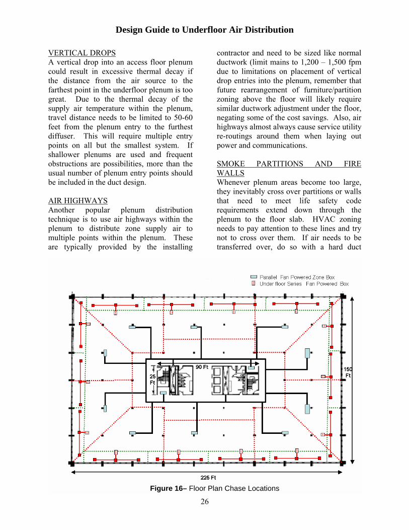
VERTICAL DROPS A vertical drop into an access floor plenum could result in excessive thermal decay if the distance from the air source to the farthest point in the underfloor plenum is too great. Due to the thermal decay of the supply air temperature within the plenum, travel distance needs to be limited to 50-60 feet from the plenum entry to the furthest diffuser. This will require multiple entry points on all but the smallest system. If shallower plenums are used and frequent obstructions are possibilities, more than the usual number of plenum entry points should be included in the duct design. AIR HIGHWAYS Another popular plenum distribution technique is to use air highways within the plenum to distribute zone supply air to multiple points within the plenum. These are typically provided by the installing
contractor and need to be sized like normal ductwork (limit mains to 1,200 – 1,500 fpm due to limitations on placement of vertical drop entries into the plenum, remember that future rearrangement of furniture/partition zoning above the floor will likely require similar ductwork adjustment under the floor, negating some of the cost savings. Also, air highways almost always cause service utility re-routings around them when laying out power and communications. SMOKE PARTITIONS AND FIRE WALLS Whenever plenum areas become too large, they inevitably cross over partitions or walls that need to meet life safety code requirements extend down through the plenum to the floor slab. HVAC zoning needs to pay attention to these lines and try not to cross over them. If air needs to be transferred over, do so with a hard duct
Figure 16– Floor Plan Chase Locations
26

Design Guide to Underfloor Air Distribution
sleeve with the appropriate smoke and/or fire damper installed per code.
Heating System Design CENTRAL SYSTEM OR HYBRID How we choose to heat the perimeter zones depends primarily on the magnitude of the load and whether or not simultaneous heating and cooling is required. The need for continuous cooling in too many interior zones makes it hard to switch over the central equipment to heating. If the wintertime temperatures drop below 40ºF and the building perimeter has more than 1/4 glass area, increased SAT’s will be required to counteract the high heating loads and downdrafts along the outside walls. In either of these cases it is recommended that a separate heating system be designed for the perimeter zones, creating a hybrid system with UFAD heating being reserved for the interior. PERIMETER FAN-COILS WITH LINEAR BAR GRILLES High heating loads along the outside walls often require higher SAT’s than interior spaces need for morning warm-up or offsetting roof loads, so selecting zone fan-coils and locating them in the perimeter plenums is an ideal solution. Using either hot water or electric heating coils allows local boosting of the zone SAT above those obtained by recirculating ceiling plenum air that is traditionally stage one heating for light load conditions. Use of a linear bar grille style diffuser is recommended to spread the air out along the perimeter wall and offset the downdrafts that develop. During summer cooling this style of grill is also beneficial in treating the higher cooling loads that are typical along the perimeter of most buildings.
HEATING INTERIORS WITH CENTRAL EQUIPMENT Smaller single-story buildings are often able to switchover during the peak heating times to full heating from the central HVAC equipment. When this happens, normal control strategies for the zone terminals will control mixing of the warmer SAT with recirculated plenum air and adjust terminal fan speed to control plenum pressure so that the “cooling” diffusers will now operate properly as heating diffusers.
Control Systems UFAD systems rely on proper design and operation of the controls like any other system. Listed below are concepts and concerns that, if incorporated into the design, will result in maintaining the stratification layer and its many benefits:
• Most UFAD systems use pressurized plenums and CAV passive diffusers, requiring some type of pressurization control on either the zone mixing box or central equipment.
• Zone control with CAV diffusers requires adjustment of the supply air temperature at the air terminal. This is best accomplished using Parallel Fan Powered Mixing Boxes (PFPMB) connected to the zone ceiling plenum return air that mixes with the primary air.
• Resetting Supply Air Temperature up under light loads allows additional hours of outdoor air economizer cooling, especially in drier climates.
• Nighttime pre-cooling, done correctly to avoid potential condensation on the plenum surfaces, can offset or delay thermal decay of the zone SAT.
27

Design Guide to Underfloor Air Distribution
• Thermostat mounting heights are often being set lower because of ADA (Americans with Disabilities Act), from 54 to 48 inches above the access floor. This is actually a benefit because if mounted too high the thermostat would be sensing the higher temperatures near the stratification layer, requiring adjusting the set point upwards to compensate.
• Systems, which use Parallel Fan Powered Mixing Boxes to control the zone primary airflow for ventilation requirements, can use Demand Controlled Ventilation, DCV, to reduce primary airflow in lower occupancy periods resulting in additional energy savings.
• Control requirements of ASHRAE Standard 90.1 should be adhered to. Including setback requirements and optimum start requirements.
TYPICAL CONTROL SEQUENCES (Up To Two 45X Mixing Boxes Serving A Common Underfloor Plenum): Plenum mixing boxes with variable speed fans can provide pressure and temperature control for plenums serving interior zones, and exterior zones using a separate perimeter heating system. This control sequence has the capability to over pressurize the plenum at start-up or during high load requirements. Typical operating sequence is shown in figure 17.
• The sequence shows basic VAV control of the primary air.
• The fan provides plenum temperature control by varying the amount of recirculated air introduced into the plenum, while the primary air damper simultaneously maintains the plenum pressure by controlling the amount of primary air introduced into the plenum.
• A wall mounted space temperature sensor located in the zone will sense load requirements.
• As the zone’s cooling load decreases, the fan speed increases, which increases the amount of recirculated air drawn in from the ceiling plenum.
• Simultaneously, the amount of primary air is reduced to maintain a constant plenum pressure.
• The terminal fan will operate whenever the primary air source is operating.
System Start-up • Points 1 to 2 from figure17 indicate
that maximum cooling airflow is established by the user-defined maximum cooling plenum pressure set point until the zone comes under control at point 2. The fan operates at minimum speed.
• From point 2, slowing the primary airflow until the minimum cooling plenum pressure set point is reached at point 3 reduces the plenum pressure.
Typical Cooling Operation • Point 3 indicates that the zone
temperature is above the control (heating) set point; the plenum pressure is maintained at the user-defined minimum cooling plenum pressure setpoint.
• At point 4 from figure17, the zone temperature decreases; increasing the fan speed to introduce more recirculated air, while simultaneously reducing the primary airflow, increases the plenum temperature. The plenum pressure remains constant at the user-defined minimum cooling plenum pressure set point.
• As indicated by points 4 to 5, should the zone temperature continue to fall the primary air damper will close,
28

Design Guide to Underfloor Air Distribution
29
but not below the user defined minimum ventilation set point at point 5 (may be set to zero), while the fan provides recirculated air to maintain the plenum pressure set point.
Heating Operation
• Upon receiving a signal for heating and heated air is being provided from the air source, the system heating-mode is automatically in effect.
• If the zone temperature is above the occupied heating setpoint, the primary air damper modulates to maintain the minimum heating plenum pressure set point. The fan operates at minimum speed.
• Should the zone temperature fall, the plenum pressure will increase up to the user-defined maximum heating plenum pressure set point. The
control may be configured to provide constant volume heating for a constant supply of heated air to the zone.
Morning Warm-up
• Upon receiving a morning warm-up signal generated by the air source controller, the primary air damper will modulate to maintain the maximum heating plenum pressure set point if the zone temperature is below the occupied heating set point. This allows a maximum quantity of warm primary air to be delivered to the zone. As the zone’s temperature rises, the plenum pressure is reduced to the minimum heating plenum pressure. The terminal fan operates at minimum speed.
UFAD Control Operating Sequences
Min. Fan Airflow
Occupied Cooling Set point
Maximum Fan Airflow
Plenum Pressure (Minimum Cooling)
Minimum Ventilation
Plenum Temperature Cool
Warmer
4
5
5
4
3
Occupied Heating Setpoint
(Heating & Morning Warm-up)
Plenum Pressure (Maximum Cooling)
Primary Airflow 2 1
Figure 17 – Carrier UFAD Control Sequence Equipment Cooling
LEGEND NTFC – Nighttime Free Cooling --------- Air Source Supplying Heated Air Air Source Supplying Cool Air

Design Guide to Underfloor Air Distribution
TYPICAL CONTROL SEQUENCES (Three or more 45X Mixing Boxes Serving a Common Underfloor Plenum): For applications requiring multiple mixing boxes serving a common plenum, it is necessary to maintain a balance between each of the mixing units. To accomplish this, plenum mixing boxes with variable speed fans can provide constant cfm and temperature control for these large common plenums. A Typical operating sequence is shown in figure 18.
• The sequences show basic VAV control of the primary air.
• The control provides volume airflow from each terminal into a common access floor plenum, thus maintaining the plenum pressure constant during both cooling and heating. The fan provides plenum temperature control by varying the amount of recirculated air introduced into the plenum, while the primary air damper simultaneously maintains the constant volume airflow set point by controlling the amount of primary air introduced into the plenum.
• A wall mounted space temperature sensor located in the zone will sense load requirements.
• As the zone’s cooling load decreases, the fan speed increases, which increases the amount of recirculated air drawn in from the ceiling plenum.
• Simultaneously, the amount of primary air is reduced to maintain constant airflow into the plenum.
• The terminal fan operates whenever the primary air source is operating.
System Start-up
• Points 1 to 4 from figure 18 indicates that maximum cooling airflow is provided by primary air until the
zone comes under control at point 4. The fan operates at minimum speed.
Typical Cooling Operation
• Point 3 indicates that the zone temperature is above the control (heating) set point; the terminals primary airflow is maximized to provide cold air to the plenum and cool the space. The fan is at a minimum airflow and the total volume of air is maintained at the required constant airflow set point.
• At point 4 from figure 18, as the zone temperature decreases; the discharge air temperature from the terminal into the plenum is increased by increasing the fan speed to introduce more recirculated air, while simultaneously reducing the primary airflow to maintain the total airflow into the access underfloor plenum.
• As indicated by points 4 to 5, should the zone temperature continue to fall the primary air damper will close, but not below the user defined minimum ventilation set point at point 5 (may be set to zero), while the fan provides recirculated air to maintain constant airflow into the underfloor access plenum.
Heating/Morning Warm-up
• Upon receiving a heating signal generated by the air source controller, (or a primary temperature sensor is installed to detect that the air source is heating), the heating mode is automatically in effect and the primary air damper is modulated to maintain constant airflow into the plenum. The fan operates at minimum speed.
30

Design Guide to Underfloor Air Distribution
31
Occupied Control Setpoint
Resulting Plenum Pressure
(Configured Heating)
Warmer
Maximum Fan Airflow
Plenum Temperature
Total Supply Airflow to Plenum
Maximum Primary Airflow
Cooler
Minimum Primary Airflow Minimum Fan Airflow Ventilation Fan
Figure 18 – Carrier UFAD Control Sequence – Equipment Cooling
1 4 2 3
5
4
5
UFAD Control Operating Sequences

Design Guide to Underfloor Air Distribution
• Controls costs should be similar to traditional systems when basic zoning is unchanged.
Installation Costs Many owners and developers have found that raised floor systems with UFAD significantly reduce costs associated with space reconfiguration. With the national churn rate now approaching 50%, it is not unexpected to find that many new office buildings use raised flooring. Buildings using UFAD systems have certain cost components that make them more expensive than traditional systems and compensating ones that lower the overall price premium that currently exist for this application. Recent job costs show that raised floor can represent a cost increase of from $3 to $5 per square foot. A few of these cost components are worth mentioning:
• Raised floor systems have the potential to reduce slab-to-slab heights by as much as 6 to 12 inches per floor. This is particularly beneficial in mid-rise and high-rise markets with zoning code height limitations.
• Testing and balancing savings can be realized from CAV pressurized plenum designs, which are essentially self-balancing.
Energy usage UFAD systems have the potential to save energy in comparison to traditional designs. The bulk of these savings come from reduced fan energy associated with lower static pressures and overall CFM reductions created by the stratification layer partial displacement ventilation effect. Documented energy costs savings remain difficult to predict because to date there is no energy simulation software that accurately models UFAD system performance.
• The raised floor system is the
component with the single largest cost increase, which should be cost justified based on the benefits to the entire service delivery system (HVAC, power, voice and data) and not against the UFAD alone.
• Local building and fire inspectors may require sprinkler protection if plenum depth exceeds 18 inches and often require smoke detectors within the plenum.
O&M Considerations • Generally, HVAC costs for central
cooling and heating equipment and ductwork mains are no different for UFAD systems.
Office building UFAD systems are quite new, making it difficult to get actual owning and maintenance cost data to compare them against traditional HVAC systems. Operations and maintenance costs are primarily replacement costs for equipment, and labor expenses associated with maintaining the HVAC system and responding to occupant complaints. While many engineers believe that UFAD may prove to be more costly to service, research suggests that the frequency of occupant
• Diffuser costs are dependent on the type(s) chosen for the majority of air delivered.
• If a relatively open underfloor plenum can be used, significant ductwork savings can be realized compared to the typical overhead air distribution system.
32

complaints will be reduced when they are given some individual control of their local environment. RECOMMENDATIONS
1. Do not eliminate the suspended ceiling. Shallow up the ceiling plenum and use it as a return air plenum, gaining additional airflow benefits from assigning greater amounts of cooling load directly to the return air.
2. Keep plenum depths below 18 inches to avoid potential requirement for underfloor sprinklers.
3. Do not use too many zoning barriers in the plenum or you will restrict the ease of future rezoning and running of service utilities to various points of use.
4. Using multiple vertical drops avoids air highways, while meeting the 50-60 foot guideline for maximum travel to the farthest diffuser.
5. Do not include excess safety factors; airflows need to closely match load requirements within the occupied zone so as not to over air the system.
Tests have shown an ideal airflow of 0.6 cfm/sqft for good mixing while maintaining the stratification height at 6 feet and keeping the room temperature gradient below 5º F.
6. Carefully run loads for both Qoccupied and Qunoccupied, and determine if load credits can be taken; equipment size reduction will benefit the job costs.
7. Select diffusers so that T50 throws are around 4-5 feet so as not to disturb the stratification zone. Use CAV passive swirls in the interior and uniformly loaded large perimeter spaces.
8. Hybrid designs, using conventional VAV in high load/variable load situations, maximizes the benefits of the lower AHU supply air temperatures and keeps summertime humidity concerns under control.
9. Placing returns over heat producing equipment and/or at the outside wall when high solar loads exist will maximize benefit of the partial displacement ventilation effect.
10. DDC controls should be considered as a basis of design for realizing true UFAD benefits.
33
Design Guide to Underfloor Air Distribution
References Bauman, Fred S., 2003. “Underfloor Air Distribution (UFAD) Design Guide. American Society of Heating, Refrigerating and Air-Conditioning Engineers, Inc. Building Owners and Managers Association (BOMA) International and ULI, the Urban Land Institute. 1999. “What do office tenants want”. IFMA. 1997. Benchmark III International Facility Management Association, Houston Tex. ASHRAE. 1990. ANSI/ASHRAE Standard 113-1990, Method of testing for room air distribution. Atlanta: American Society of Heating, Refrigerating and Air-Conditioning Engineers, Inc. ASHRAE. 1992 ANSI/ASHRAE Standard 55-1992, Thermal environmental conditions for human occupancy. Atlanta: American Society of Heating, Refrigerating and Air-Conditioning Engineers, Inc. ASHRAE. 2001b. ANSI/ASHRAE Standard 62-2001, Ventilation for acceptable indoor air quality. Atlanta: American Society of Heating, Refrigerating and Air-Conditioning Engineers, Inc. ASHRAE. 2001c. ANSI/ASHRAE Standard 90.1-2001, Energy standard for buildings except low-rise residential buildings. Atlanta: American Society of Heating, Refrigerating and Air-Conditioning Engineers, Inc.
34