Mass Customization Capabilities in Practice – Introducing ...

DESIGN FOR MASS CUSTOMIZATION OF MEDICAL DEVICES VIA PLATFORM
METHODOLOGY
A Thesis Presented
by
Tathagat Siddharth Pathak
to
The Department of Mechanical and Industrial Engineering
in partial fulfillment of the requirements
for the degree of
Master of Science
in the field of
Industrial Engineering
Northeastern University
Boston, Massachusetts
August 2014

i
Abstract
The medical device industry seeks to deliver customized products to a vast variety of its
customers. Medical device companies are looking for ways to decrease the product
development cost and at the same time increase heterogeneity in products. In other
words, the industry is looking for new methods and approaches to mass customize
medical devices. This thesis presents a novel design methodology for mass customization
of medical devices. The thesis proposes an approach to developing individualized devices
to custom fit to the patient’s physiology. It applies techniques from mass customization to
design medical devices to contain cost and handle large varieties of patient geometries. It
uses the Design Structure Matrix (DSM), scalable product architecture and product
platforms design processes to develop mass customized medical device concepts. The
proposed method is demonstrated on hip and knee implant products to show its
applicability to numerous medical devices. The hip and knee implants are divided into
components and then analysed utilizing the DSM and product platform design techniques
to generate scalable and modular implants each with different shape and size. The
developed design implants are then analysed using finite element analysis to ensure that
the new components can support the forces encountered by them once they are implanted
in a human body.

ii
Acknowledgements
First and foremost, I would like to express my most sincere gratitude to my advisors Dr.
Abe Zeid, Dr. Sagar Kamarthi and Dr. Tucker Marion for their guidance and patience. I
thank them for teaching me all the skills necessary to complete this journey.
I would also like to thank Andrew G. Wallace and Adam Medla for their help in the 3D
Design of Hip & Knee Implant and special thanks to Donald W. Blanchet M.S.M.E for
his help with the stress analysis of the implants.
I would like to thank my parents, Siddharth Pathak and Anokhi Pathak, my American
family, Gretchen Bronke, Bob Bronke and Doris Neilson, my good friend Sandeep Lahiri
and my mentors, Stoney Lingo and Helder Simoes for their endless support and patience.
Without them I couldn’t have come this far. I thank them for always being there for me.
I am grateful to Northeastern University for supporting my research. This work was
supported by Northeastern University Tier 1 Interdisciplinary Research Proof of Concept
Grant, “Research Frontiers in Healthcare Mass Customization for Personalization of
Diagnosis, Care and Cure”.
Thank You Very Much God. Jai Shri Krishna.

iii
Table of Contents
Abstract ................................................................................................................................ i
Acknowledgements ............................................................................................................. ii
Table of Contents ............................................................................................................... iii
List of Figures .................................................................................................................. viii
List of Tables .................................................................................................................... xii
Chapter 1 Introduction ........................................................................................................ 1
1.1 Overview of Medical Devices .................................................................................. 1
1.2 Problem Statement .................................................................................................... 2
1.3 Proposed Solution ..................................................................................................... 2
1.4 Thesis Contribution ................................................................................................... 3
Chapter 2 Tools for Developing Mass Customized Medical Devices ................................ 4
2.1 Product Platform Methodologies .............................................................................. 4
2.2 Product Review ......................................................................................................... 6
2.3 Design Structure Matrix (DSM) ............................................................................... 7
2.4 Energy Material-Signal Diagram (EMS) .................................................................. 9
2.5 Interface Diagram ................................................................................................... 11
2.6 Design for Mass Customized Medical Devices (DMCMD) ................................... 11

iv
Chapter 3 Hip Implant Customization .............................................................................. 14
3.1 Product Review ....................................................................................................... 14
3.2 Design Structure Matrix (DSM) ............................................................................. 16
3.3 Energy Material-Signal Diagram (EMS) ................................................................ 17
3.4 Interface Diagram ................................................................................................... 18
3.5 Customized Designs................................................................................................ 19
3.6 3-D Prototype of Designs...................................................................................... 21
Chapter 4 Knee Implant Customization ............................................................................ 23
4.1 Product Review ....................................................................................................... 23
4.2 Design Structure Matrix (DSM) ............................................................................. 24
4.3 Energy Material-Signal Diagram (EMS) ................................................................ 25
4.4 Interface Diagram ................................................................................................... 26
4.5 Customized Designs................................................................................................ 28
4.6 3-D Prototype of Designs...................................................................................... 31
Chapter 5 3D modeling of Hip and Knee Implants .......................................................... 32
5.1 Hip Implant Products Design .................................................................................. 32
5.1.1 Acetabular Cup Design ........................................................................................ 32
5.1.2 Femoral Head Design .......................................................................................... 34
5.1.3 Plastic Liner Design ............................................................................................. 37
5.1.4 Femoral Stem Design ........................................................................................... 38

v
5.2 Hip Implant Assembly Setup .................................................................................. 41
5.3 Knee Implant Products Design ............................................................................... 41
5.3.1 Femoral Component 1 Design ............................................................................. 42
5.3.2 Femoral Component 2 Design ............................................................................. 42
5.3.3 Plastic Spacer Design ........................................................................................... 43
5.3.4 Tibial Component 1 Design ................................................................................. 46
5.3.5 Tibial Component 2 Design ................................................................................. 46
5.4 Knee Implant Assembly Setup ................................................................................ 47
5.5 Hip and Knee Implant Products Rapid Prototyping ............................................... 48
6.1 Problem Setup: Assembly Analysis ........................................................................ 51
6.2 Material Properties .................................................................................................. 52
6.3 Contact Interactions ................................................................................................ 53
6.4 Loading and Boundary Conditions ......................................................................... 54
6.5 Meshing................................................................................................................... 54
6.6 Stress Analysis Results ........................................................................................... 55
6.6.1 Hip Implant with Circular Interface ..................................................................... 55
6.6.2 Hip Implant with Square Interface ....................................................................... 56
6.6.3 Hip Implant with Elliptical Interface ................................................................... 57
6.7 Displacement Results .............................................................................................. 58
6.7.1 Hip Implant with Circular Interface:.................................................................... 58

vi
6.7.2 Hip Implant with Square Interface ....................................................................... 58
6.7.3 Hip Implant with Elliptical Interface ................................................................... 59
6.8 Factor of Safety Results .......................................................................................... 61
6.8.1 Hip Implant with Circular Interface ..................................................................... 61
6.8.2 Hip Implant with Square Interface ....................................................................... 61
6.8.3 Hip Implant with Elliptical Interface ................................................................... 62
Chapter 7 Finite Element Analysis of Knee Implant ........................................................ 64
7.1 Problem Setup: Assembly Analysis ........................................................................ 64
7.2 Material Properties .................................................................................................. 65
7.3 Contact Interactions ................................................................................................ 65
7.4 Loading and Boundary Conditions ......................................................................... 66
7.5 Meshing................................................................................................................... 67
7.6 Results ..................................................................................................................... 68
7.6.1 Knee Implant customized products stress analysis .............................................. 68
7.6.2 Knee Implant customized products FEA displacement ....................................... 71
7.6.3 Knee Implant customized products FEA Factor of Safety ................................... 73
Chapter 8 Discussion and Conclusion .............................................................................. 76
8.1 Discussion ............................................................................................................... 76
8.2 Conclusion .............................................................................................................. 78
References ......................................................................................................................... 80

vii
Appendix: Hip implant analysis for different materials ................................................... 85

viii
List of Figures
Figure 2.1: Module based product family development architecture ................................. 4
Figure 2.2: Sony Walkmans™ module based product ....................................................... 5
Figure 2.3: Example of braun coffee makers modular products ......................................... 5
Figure 2.4: Rolls Royce scalar product family ................................................................... 6
Figure 2.5: Example of DSM application on interaction of components .......................... 8
Figure 2.6: Steps for developing DSM for medical device X ............................................ 8
Figure 2.7: EMS diagram .................................................................................................. 10
Figure 2.8: Interface diagram ............................................................................................ 11
Figure 2.9: Proposed Design for Mass Customized Medical Devices (DMCMD) .......... 13
Figure 3.1: A hip and its implant ...................................................................................... 15
Figure 3.2: DSM of hip implant product ......................................................................... 16
Figure 3.3: EMS of a hip implant product ........................................................................ 17
Figure 3.4: Interface diagram of hip implant .................................................................... 18
Figure 3.5: Present interface of the hip implant ................................................................ 18
Figure 3.6: New proposed square and elliptical interfaces .............................................. 18
Figure 3.7: Solidworks™ CAD module scale stem and head platform ........................... 20
Figure 3.8: Solidworks™ CAD module scale hip products ............................................ 21
Figure 3.9: 3D Hip Implant Product Prototype ............................................................... 22

ix
Figure 4.1: A knee and its implant .................................................................................... 23
Figure 4.2: Total knee replacement ................................................................................. 24
Figure 4.3: DSM of knee implant product ........................................................................ 25
Figure 4.4: EMS diagram of knee implant product .......................................................... 26
Figure 4.5: Interface diagram of knee implant .................................................................. 27
Figure 4.6: Present interface between plastic spacer and tibial component ..................... 27
Figure 4.7: Proposed two new common interfaces ........................................................... 27
Figure 4.8: Modular customized plastic spacer platforms of the knee implant ................ 29
Figure 4.9: Modular customized knee implant products .................................................. 30
Figure 4.10: Modular customized knee implant 3D prototype products .......................... 31
Figure 5.1: Acetabular cup sketch .................................................................................... 33
Figure 5.2: Tapped hole sketch ......................................................................................... 33
Figure 5.3: Design tree and acetabular cup design ........................................................... 34
Figure 5.4: Femoral head sketch ....................................................................................... 34
Figure 5.5: Dowel hole for femoral stem with circular interface ..................................... 35
Figure 5.6: Elliptical hole in the head for the stem with elliptical interface ..................... 35
Figure 5.7: Square hole in the head for the stem with square interface ............................ 36
Figure 5.8: Femoral heads for stems with various interfaces ........................................... 36
Figure 5.9: Design tree of femoral head ........................................................................... 36
Figure 5.10: Plastic liner sketch ........................................................................................ 37

x
Figure 5.11: Design tree and plastic liner design .............................................................. 38
Figure 5.12: Base sketch for stem interfaces .................................................................... 38
Figure 5.13: Lofted femoral stem ..................................................................................... 39
Figure 5.14: Design tree and stem with circular interface extruded ................................. 40
Figure 5.15: Stem with square and elliptical interface extruded ...................................... 40
Figure 5.16: Hip implant assembly and mates .................................................................. 41
Figure 5.17: Femoral component 1 design ....................................................................... 42
Figure 5.18: Femoral component 2 design ....................................................................... 43
Figure 5.19: Plastic spacer platform 1 design ................................................................... 44
Figure 5.20: Plastic spacer platform 2 design ................................................................... 44
Figure 5.21: Plastic spacer platform 3 design ................................................................... 45
Figure 5.22: Plastic spacer platform 4 design ................................................................... 45
Figure 5.23: Tibial component 1 design ........................................................................... 46
Figure 5.24: Tibial component 2 design ........................................................................... 47
Figure 5.25: Knee implant assembly and mates ............................................................... 48
Figure 5.26: Dimension sst 1200es rapid prototyping machine ....................................... 49
Figure 5.27: 3D prototypes of hip and knee implant designs ........................................... 50
Figure 6.1: Contact sets for FEA of hip implant products ................................................ 54
Figure 6.2: Loading and boundary conditions for hip implant stress analysis ................. 55
Figure 6.3: Module scale hip implant mesh ...................................................................... 56

xi
Figure 6.4: FEA of customized hip product with circular interface ................................. 57
Figure 6.5: FEA of customized hip product with square interface ................................... 57
Figure 6.6: FEA of customized hip product with elliptical interface ............................... 58
Figure 6.7: Displacement of customized hip product with circular interface ................... 59
Figure 6.8: Displacement of customized hip product with square interface..................... 60
Figure 6.9: Displacement of customized hip product with elliptical interface ................. 61
Figure 6.10: Factor of safety of customized hip Product with circular interface ............. 62
Figure 6.11: Factor of safety of customized hip product with square interface ............... 63
Figure 6.12: Factor of safety of customized hip product with elliptical interface ............ 64
Figure 7.1: Contact sets for FEA of knee implant products ............................................. 67
Figure 7.2: Loading and boundary conditions for knee implant stress analysis ............... 68
Figure 7.3: Modular knee implant mesh ........................................................................... 69
Figure 7.4: FEA of modular customized knee products ................................................... 71
Figure 7.5: Displacement of modular customized knee products ..................................... 74
Figure 7.6: Factor of safety of modular customized knee products .................................. 76
Figure 8.1: Operation phases in DMCMD method ........................................................... 76
Figure A.1: Different material FEA results of hip product with circular interface .......... 86
Figure A.2: Different material FEA results of hip product with elliptical interface......... 87
Figure A.3: Different material FEA results of hip product with square interface ............ 88

xii
List of Tables
Table 6.1: Material Properties of Ti6Al4v ........................................................................ 52
Table 6.2: Material Properties of Cross-Linked High Density Polyethylene ................... 52

1
Chapter 1 Introduction
1.1 Overview of Medical Devices
A medical device is a biocompatible artificial object utilized or inserted in the human
body to diagnose, cure or avert a disease or a distinct condition or substituted for
dysfunctional body unit [1]. Applications of medical devices are highly complicated due
to complex human physiology. Illustrations range from simple devices such as
thermometers and tongue depressors to cutting edge devices like implants and prostheses.
According to the Food and Drug Administration (FDA), medical devices are categorized
into three classes: class 1, 2 and 3, based on the level of control required to prove their
safety and effectiveness.
Class 1 devices, are subjected to the least regulatory control, they are not critical to
support human life and are considered less likely to cause illness or injury. Elastic
Bandages, nitrile gloves and surgical instruments are some of the examples of Class 1
Devices. About 47% of medical devices fall under this category out of which 95 % are
exempted from the regulatory process [2].
Class 2 devices pose moderate amount of risks and that is why they are approved through
the 510(k) FDA approval process. Examples of Class 2 devices include powered
wheelchairs, pregnancy test kits, and hip and knee implants. Nearly 43% of medical
devices fall under this category [2].
Class 3 devices pose the maximum amount of risk to human health and safety. Therefore
2
they are the most regulated devices by the FDA among all 3 classes of devices. These
devices have to pass through the premarket approval (PMA) process in which the device
manufacturer has to submit pre-clinical as well as clinical information to demonstrate its
safety and effectiveness. These devices also require general as well as special controls
[1]. Examples of Class 3 devices include implantable pacemakers, breast implants, and
automated external defibrillators. Approximately 10% of medical devices fall under this
category [2].
1.2 Problem Statement
Medical device companies either develop one-size-fits-all products or a highly
customized product for very rare cases. This represents an opportunity for developing
customized low cost products at the individual level. However, many companies are
finding it difficult to customize medical devices at mass scale while still being dexterous
in creating individualized devices. Additionally, firms are under pressure to produce
successive generations of devices in order to reduce the product development time and
cost. As documented by Dalgarno, et al. [3], companies are meeting the challenge by
adopting mass customization strategies for creating individualized devices. Mass
customization of devices, according to Marion et al. [4], is “the ability to design and
manufacture a customized product at mass production speed and efficiency.”
1.3 Proposed Solution
The medical device industry can leverage product platform methodology for developing a
variety of customized products. This will lead to a reduction in manufacturing costs and

3
process complexity, while increasing the variety of customized products. Ulrich and
Robertson have mentioned that “by sharing components and production processes across
a platform of products, companies can develop differentiated products efficiently,
increase the flexibility and responsiveness of their manufacturing processes, and take
market share away from those competitors that develop only one new product at a time.”
[5].
1.4 Thesis Contribution
The purpose of this thesis is to develop a methodology for designing mass customized
medical devices leveraging product platform techniques. This approach combines several
established tools to form a unique methodology which will assist the design engineer to
identify and arrange component architecture and interfaces. In the design process, since
medical devices are complex compared to other consumer products, we add a dimension
of the Design Structure Matrix (DSM) to understand the relationship of each part with
other parts of a complex system [11]. Additionally, we use the concept of modularization
to organize complex designs and process operations more efficiently by decomposing
complex systems into simpler portions [12]. Combining DSM, mass customization,
product platforms and modularity, a firm can economically develop a customized medical
device for an individual.

4
Chapter 2 Tools for Developing Mass
Customized Medical Devices
2.1 Product Platform Methodologies
There are two main custom platform based device development techniques:
Module-Based Product Family Development: In this approach several different
products are created by adding, subtracting or replacing one or a combination of modules
from the product platform [6] as shown in Figure 2.1.
Figure 2.1: Module-based product family development architecture [6]
Following are some of the example of modular product families from the literature:
Sony developed 250+Walkmans™ in the 1980’s by leveraging modular designs in
USA. Example of Walkmans™ is shown in Figure 2.2 [7].

5
Figure 2.2: Sony Walkmans™ module based product [7]
Braun Family of Coffee Makers, this product family is another example of a
modular platform as shown in Figure 2.3 [6]
Figure 2.3: Example of braun coffee makers modular products [6]
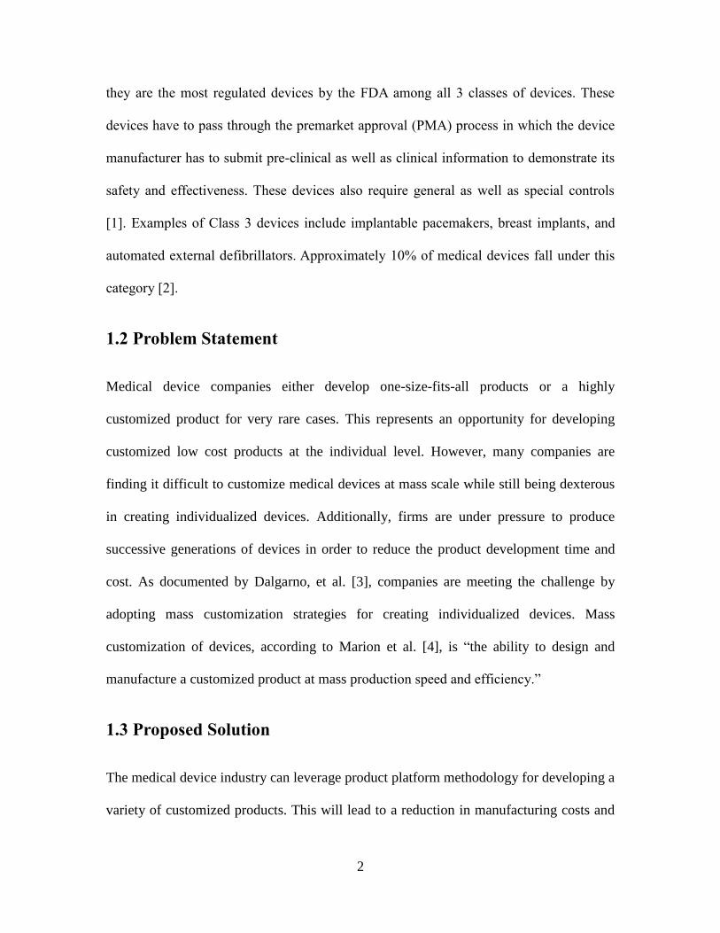
Scale Based Product Family Development: In this technique, one or more dimensions
of the product platform is increased or decreased to develop a variety of products for
various market niches [8]. Rolls Royce utilized a scalar platform to develop a variety of
products delivering different horsepower and thrust by scaling its RTM 322 design
example, as shown in Figure 2.4.
6
Figure 2.4: Rolls Royce scalar product family [8]
Integrating four different paradigms of research: DSM, product platforms in the
form of energy material signal diagram, modularity and mass customization in the form
of interface diagram and customized designs respectively. Combining these techniques
leads to the formation of a unique methodology termed Design for Mass Customized
Medical Devices (DMCMD). The remainder of this thesis applies the developed concept
to customizing hip and knee implant products. Multiple designs are developed for each
implant. Finite element analysis is performed on each design in the Solidworks™ CAD
tool and each design is then critiqued. The method and model are discussed in chapter 7
and conclusions are drawn with implications for future work in chapter 8.
2.2 Product Review
It is necessary to understand the present design of the medical device product to begin the
first phase of mass customized product development. The knowledge gained from this
research will help one to develop a roadmap for a particular medical device. Next product

7
platforms methodology is applied to develop the modular, scalar or module scale
platform. Utilizing that platform numerous customized products are developed.
Tools covered in the remainder of this chapter have not been applied to medical implants.
In this thesis they are applied innovatively to the customization of medical devices,
specifically medical implants.
2.3 Design Structure Matrix (DSM)
According to Lindemann [13], a DSM is “a simple tool to perform both the analysis and
the management of complex systems. It enables the user to model, visualize, and analyze
the dependencies among the entities of any system and derive suggestions for the
improvement or synthesis of a system”. It is also known as a problem solving matrix
(PSM). The DSM is a square matrix which can be used in understanding various complex
systems [15].
DSM-based design methodologies are applied in various disciplines. They are used for
project scheduling and management in new product development [14]. A DSM helps one
to analyze a particular system using powerful clustering algorithms. In this thesis a
component-based DSM, which is also known as architecture DSM is used. Component-
based DSM success has been proven by Pimmler and Eppinger [16] at Ford Motor
Company for developing modular design for an automatic climate control system. Figure
2.5 shows an example of DSM. Utilizing the DSM in developing a customized medical

8
device platform is unique to the overall concept of Design for Mass Customized Medical
Devices DMCMD.
Figure 2.5: Example of DSM application on interaction of components.
A component-based DSM is useful to decompose, document and analyze the medical
device X. Since medical devices are very complex assemblies, a DSM serves as a tool to
manage and decompose the device. These are the steps we are going to follow for
understanding the complexity of the medical device also shown in Figure 2.6:
(1) Decompose the device into elements
(2) Understand and document the interactions between the elements
(3) Analyze the potential reintegration via clustering
Figure 2.6: Steps for developing DSM for medical device X

9
2.4 Energy Material-Signal Diagram (EMS)
In order to apply mass customization, it is important to develop a framework for the
device. During the design process, it is necessary to separate the components that interact
with the customer/patient the most. Since some of the medical devices are fitted inside
the patient’s body, it can be a challenge to understand the component interaction with the
body parts as well as the other component/s of the device itself.
As defined by Fujimoto [17] product architecture is “the overall mapping to envision and
identify product functions and distribute them through common elements and critical
interfaces through which vital information and value creation are shared and realized.”
This will be useful in developing modular product architecture with platform-based
design. Steps for the modular product architecture are as follows [17]:
(1) Find the desirable functions of the product
(2) Divide the functions depending on various components
(3) Plan the interfaces among the component parts which interact
The Energy Material Signal (EMS) diagram is useful for developing a modular medical
device architecture that is an extension of “black box” model, which is used for defining
input and output of a system. It is a simple diagram used for visualizing the
electromechanical system in addition to inputs and outputs to and from the system [18].
The EMS diagram is an augmentation of the function diagram; it is a visual tool for
recognizing energy, material and/or signal flows, which are either hurtful or incompetent
[19].

10
Figure 2.7: EMS diagram of a hip implant product
The EMS shown in Figure 2.7 is an example of how it can be used for developing a
modular medical device platform. Various components are named starting from C1 to C5.
As one can see in the Figure, the primary interface C1 could be an electric switch, which
when pressed activates a motor to provide mechanical movement to C2. This in turn
initiates the electrical input and oil transfer to C3 in addition to providing mechanical
input to C4. Finally, C4 provides the mechanical input to C5. The dashed rectangular
shapes in the Figure represent the possible platforms for the particular product. By
utilizing EMS, one can also define a component or a platform, which can be mass
customized [4]. By decomposing a medical device via EMS, one can develop platform
architecture for the device in addition to identifying possible components for mass
customization. EMS as described is used for understanding the flow between various
components of the device. In this thesis, EMS is utilized in a different and distinct way in
order to understand the connection between the medical device components.

11
2.5 Interface Diagram
The interface diagram can be developed using the information gained from the EMS
diagram. Through the interface diagram one will be able to find common components or
parts for mass customization [20]. As can be seen in Figure 2.8, there are a total of three
platforms. The mass customized platform, which includes C2 and C3, does not interact
with the customer but interfaces internally with components C1 and C4. The interface
diagram was used to identify a mass customized platform as compared to mass
customized components, thus contributing in the development of modular, scalar or
module scale platform for customized device design.
Figure 2.8: Interface diagram
2.6 Design for Mass Customized Medical Devices (DMCMD)
The method described above as a combination of various tools is explained as a whole in
this section. Utilizing the proposed tool, an engineer can mass customize any medical
device with ease. The design for mass customized medical devices (DMCMD) is a new

12
product platform methodology to be applied in the development of customized medical
device products leveraging the combination of product platform methodology described
above. The DMCMD shown in Figure 2.9 starts with product research to identify the
proper medical device X. Secondly the DSM is applied to understand the complexity of
the medical device X by decomposing, documenting and analysing the device. Step 3
defines the platform for the medical device using the EMS diagram in addition to
identifying the mass customized component in the platform developed. Step 4 uses the
Interface diagram to define various interfaces for the mass customized component
identified. Step 5 generates a 3D design of the medical device X using design software.
Step 6: A 3D prototype is constructed to verify the design. Figure 2.9 show the steps of
DMCMD.

13
Figure 2.9: Proposed design for mass customized medical devices (DMCMD) method

14
Chapter 3 Hip Implant Customization
3.1 Product Review
One of the most common implant operations among patients is the hip replacement using
a hip implant. The hip implant has been chosen as one of the examples to show the
impact of our method on medical devices. Hip implants [21] consist of a ball and socket
joint in which the pelvis is the socket inside which the femur ball fits. Damage in the hip
can be due to either osteoarthritis as shown in Figure 3.1(A) or wear and tear arthritis.
The latter type of arthritis is caused by degeneration of cartilage over time which causes
the bone ends to rub against each other.
Hip implants are common practice today. The artificial hip joint consists of 4 parts
including femoral stem, femoral head, polyethylene liner and acetabular cup as shown in
Figure 3.1(B).
There are various types of hip implants available in the market, based on the patient
needs as listed below [22]:
(1) Stem type with acrylic cement fixation
(2) Stem type without cement fixation
(3) Stem type with hybrid fixation
(4) Bearing materials used in joint replacement
(5) Metal on metal bearings

15
(6) Ceramic on ceramic bearings
(7) Hemi surface replacement for osteonecrosis
(8) Surface replacement of the hip
The proposed method concentrates on total hip replacement without cement fixation
product which is, also known as "metal-on-plastic" hip implant as shown in Figure
3.1(C).
Figure 3.1: A hip and its implant
(A) Hip with arthritis
(B) Hip implant parts (C) Hip implant product

16
3.2 Design Structure Matrix (DSM)
Next, step 2 is applied to the hip implant product. The DSM is developed to understand
the complexity of the medical implant product. From the DSM shown in Figure 3.2 it is
clear that the femoral stem is connected to the femoral head. The femoral head and plastic
liner are both connected in a manner which makes them very important components of an
hip implant product. DSM helps one to determine which components to focus on. In this
case it is the femoral head and the plastic liner.
Figure 3.2: DSM of hip implant product
Before advancing to step 3, it is important to understand how the two end components of
the hip implant, the femoral stem and the acetabular cup, are connected to other bones.
With the help of Figure 3.3(A) one learns that femur stem is connected to condyles which
are further connected to the knee. The acetabular bone is connected to pelvic bone.

17
3.3 Energy Material-Signal Diagram (EMS)
As a third step, utilizing the EMS diagram, the hip implant is deconstructed as shown in
Figure 3.3(B). It shows that all components are mechanically connected. Three different
platforms have been developed: platform 1 for the stem, platform 2 for the head and liner,
platform 3 for the cup. Figure 3.3(B) also indicates femoral head as the mass customized
component. The next section demonstrates mass customization of this component in
detail. Thus developing various platforms will be useful for further preparing the
interface diagram.
Figure 3.3: EMS of a hip implant device
(A) End components connections[23] (B) EMS diagram of hip implant

18
3.4 Interface Diagram
As shown in Figure 3.4, one can observe that there is only one interface proposed in the
new customized hip implant product. In this Figure it can be noticed that the plastic liner
is not mentioned. The original hip implant product has the liner fixed with the cup and
therefore they are combined to make one platform in the interface diagram as platform 3.
The original circular interface is shown in Figure 3.5.The new interfaces developed are
square and elliptical in shape as shown in Figure 3.6. Both the proposed interface models
provide a better locking mechanism between head and cup.
Figure 3.4: Interface diagram of hip implant
Figure 3.5: Present interface of the hip implant
(A) Actual implant (B) CAD model

19
Figure 3.6: New proposed interfaces
3.5 Customized Designs
3D computer-aided-design (CAD) modelling of the customized hip implant has been
performed using Solidworks™. In this design the diameter of the head is scaled, utilizing
the information gained from the EMS diagram. The scalar customized platform of the
femoral head is developed as shown in Figure 3.7. As noticed in Figure 3.7 the femoral
head is scaled very similar to the Rolls Royce example [8]. By scaling the head itself one
can develop numerous products of hip implant which would fit individual's hip with
different physiologies. In addition, as in Figure 3.7, the modular stem is shown with
square and elliptical interfaces. Each provides a better locking mechanism to the femoral
head. Combining the modular stem and the scalar head makes a unique module scale hip
implant product platform. Utilizing the developed module scale platform, more products
can be generated in a manner similar to the scalar platform of the femoral head. Figure
3.8 shows a 3D model of customized hip implant products utilizing the combined module
scale platform of stem and head with the assembly of acetabular cup and liner. The 3D
design thus helps in observing the impact of DMCMD on the customization of the hip
(A) Square interface (B) Elliptical interface

20
implant product, which is further applied to the knee implant in the next section.
Figure 3.7: Solidworks™ CAD module scale stem and head platform

21
Figure 3.8: Solidworks™ CAD module scale hip products
3.6 3-D Prototype of Designs
Lastly, in order to verify the design, a 3D prototype is developed as shown in Figure 3.9.
The prototype helps in validating the design, thus proving that DMCMD is a useful
technique for the medical device industry. This technique will provide patients requiring
(A) Hip with modular square stem (B) Hip with modular elliptical stem
(C) Hip with module scale square platform (D) Hip with module scale elliptical platform

22
customized products with individualized devices at the same price of mass production of
a one-size-fits-all device.
Figure 3.9: 3D Hip Implant Product Prototype with square interface

23
Chapter 4 Knee Implant Customization
4.1 Product Review
Another very common implant operation among patients is knee replacement surgery. As
per orthopaedic info, there are more than 600,000 knee replacement surgeries performed
each year in the USA [24]. Knee replacement is a replica of a hinge joint with its
movement very similar to the hinged door. As shown in Figure 4.1(A) the tibial plate and
polyethylene part are fixed while the femoral component has the ability to bend and
straighten [25].Currently the market has around 150 varieties of knee replacement
products sold by different manufacturers [25]. Due to arthritis as shown in Figure 4.1(B)
or injury, it becomes difficult for a patient to do daily activities like walking and running.
The patient may also experience pain while sitting or lying down. Thus to reduce pain
and allow the patient to resume normal activities, knee replacement surgery is performed.
Figure 4.1: A knee and its implant
(A) Arthritic knee (B) Knee implant with various components

24
There are various different types of knee implant products available in the market as
listed below [26]:
(1) Total knee replacement
(2) Unicomparmental (partial) knee replacement
(3) Kneecap replacement
(4) Complex or revision knee replacement
DMCMD method impact is demonstrated focusing on the total knee replacement product
also known as "metal-on-plastic" knee implant as shown in Figure 4.2(A).
Figure 4.2: Total knee replacement
4.2 Design Structure Matrix (DSM)
By applying the design structure matrix (DSM), the components internal interaction of
the knee implant product can be understood. As demonstrated in Figure 4.3 there are two
main connections: one between the femoral component and the plastic spacer and the
(A) Total knee replacement components (B) X-Ray of total knee replacement
Femoral component
Tibial component
Plastic Liner

25
other between the plastic spacer and the tibial component. Analysing the DSM, it is
realised that the plastic spacer is a very important component in the customized platform
development. The reason for this is that the spacer is connected to both the hinged
femoral component and the fixed tibial component. As shown in Figure 4.2(B), the tibial
component is connected to the tibia and the femoral component is connected to the femur
[27]. This connection will be useful in the development of the energy material signal
diagram.
Figure 4.3: DSM of knee implant product
4.3 Energy Material-Signal Diagram (EMS)
As the next step in developing a customized platform, the EMS diagram is utilized to
deconstruct the functions of the knee implant thus leading to the development of a better
modular architecture as shown in Figure 4.4. The femoral component (platform 1),
which replicates the knee of a patient is connected mechanically to the femur (bone) and
plastic spacer (implant component) with a movement similar to a hinged door. The tibial
component is also connected mechanically to the plastic spacer and tibia. Both the EMS
and the DSM demonstrate the significance of the plastic spacer. Therefore the plastic
spacer is chosen to be customized, shown in Figure 4.4 as the mass customized

26
component. Additionally, potential modular platforms are also shown in the EMS
diagram inside square boxes.
Figure 4.4: EMS diagram of knee implant product
4.4 Interface Diagram
Utilizing the potential platforms information from the EMS diagram, the interface
diagram is developed to identify a common interface. This goes further to the
development of the customized modular platform. As shown in Figure 4.5 there is no new
interface proposed between the femoral component and the plastic spacer, while a new
interface is proposed between the plastic spacer and the tibial component. Figure 4.6 also
shows that at present there is no interface between the plastic spacer and the tibial
component: they are simply bonded with each other. A 3D CAD model of the two new
proposed interfaces have been developed as shown in Figure 4.7. Both proposed
interfaces shown in the Figure are similar in dimensions. The only difference is that the
interface number 2 has a keyway. The reason for developing two separate interfaces is

27
explained in detail in the 3-D modelling of the knee implant in section 4.5.
Figure 4.5: Interface diagram of knee implant
Figure 4.6: Present interface between plastic spacer and tibial component
Figure 4.7: Proposed two new common interfaces
Interface 1: Tapered circular interface Interface 2: Tapered circular interface with keyway

28
4.5 Customized Designs
3-D CAD models are developed utilizing the platforms and interfaces proposed in the
previous steps. As shown in Figure 4.8 four different platforms are identified each of
which can be used as a modular customized component to develop a range of knee
implant products. Plastic spacer platform 1 is very similar to the knee implant product
presently available on the market; the only difference is the interfaces shown in Figure
4.7. Plastic spacer platform 2 is customized by leveraging the same design as platform 1
but with more support for the femoral component, depending on the specific physiology
of the individual. Plastic spacer platform 3 is customized by developing a keyway to the
common interface proposed above, thus providing a locking mechanism between the
plastic spacer and the tibial component of the implant. Plastic spacer platform 4 is
customized by adding more material depth to platform 2 for patients who are heavy, since
most of the knee implants need to be replaced within 5-10 years due to excessive wear
and tear on the spacer. Figure 4.8 demonstrates that, numerous modular customized
platforms can be easily developed in response to the individual’s specific needs using
DMCMD concepts.

29
Figure 4.8: Modular customized plastic spacer platforms of the knee implant
As a final step in Figure 4.9, the femoral components 1 and 2 (shown in two upper
corners) are assembled with platform 1 and platform 2 (shown in the centre). These
assemblies are then combined with the tibial components 1 and 2 shown in (two lower
corners) to develop variety of customized products. As demonstrated in Figure 4.9, 8
different products starting from P1, P2, P3 to P8 are developed utilizing just 2 of the 4
modular customized platforms from Figure 4.8. A family of customized products for
patients is developed with different physiologies. This will lead to a reduction in design
cost and production cost as the same platform of plastic spacer can be used for creating 4
different products. With further femoral and tibial component designs more products
could be developed utilizing the same common plastic spacer platforms.

30
Figure 4.9: Modular customized knee implant products
Femoral Component 1 Femoral Component 2
Tibial Component 1 Tibial Component 2

31
4.6 3-D Prototype of Designs
To verify the developed design, a 3-D prototype of the customized knee implant product
is manufactured using a rapid prototyping machine. The prototypes of product P1 and P2
are shown in Figure 4.10. These prototypes are created to verify their application on real
knee implant products.
Figure 4.10: Modular customized knee implant 3D prototype products

32
Chapter 5 3D modeling of Hip and Knee
Implants
In this chapter, high level steps of various designs of the hip and knee implant products
are discussed. 3D prototype of each design is also developed and shown for the
verification of each design.
5.1 Hip Implant Products Design
Hip implant components are designed to exactly replicate the total hip replacement
product as explained in detail in chapter 3.
5.1.1 Acetabular Cup Design
Acetabular cup is one of the four components of the hip implant product as explained in
detail in chapter 3. This component is kept the same in the various hip implant products
developed.
Step 1, Draw the sketch and then revolve it 360 degree to develop the acetabular cup, as
shown in Figure 5.1.

33
Figure 5.1: Acetabular cup sketch
Step 2, the hole is taped on top of the cup with size M6x1.0, as shown in Figure 5.2.
Figure 5.2: Tapped hole sketch
The design tree and acetabular cup design are shown in Figure 5.3.

34
Figure 5.3: Design tree and acetabular cup design
5.1.2 Femoral Head Design
Femoral head is the second component of the hip implant. It is also the scalar platform
for customizing the products based on patient’s physiology as demonstrated in chapter 3.
Step 1, Draw the sketch and then revolve it 360 degree to develop the femoral head, as
shown in Figure 5.4.
Figure 5.4: Femoral head sketch

35
Step 2, a dowel hole of diameter 12 mm is developed so that the femoral stem with
circular interface could fit in the head, as shown in Figure 5.5.
Figure 5.5: Dowel hole for femoral stem with circular interface
Since in the design of the customized modular component, a locking mechanism is
proposed, two more femoral heads are designed, one with elliptical hole and other with
the square hole, to fit the appropriate customized modular femoral stem during the
assembly process as shown in Figure 5.6 and 5.7 respectively.
Figure 5.6: Elliptical hole in the head for the stem with elliptical interface

36
Figure 5.7: Square hole in the head for the stem with square interface
Finally, the variety of designs of the femoral head is shown in Figure 5.8 to demonstrate
the difference in the hole for holding the stem interface.
Figure 5.8: Femoral heads for stems with various interfaces
The sample design tree of the circular femoral head design is shown in Figure 5.9.
Figure 5.9: Design tree and circular femoral head design
(B) elliptical interface (A) square interface

37
5.1.3 Plastic Liner Design
Plastic Liner is the third component of the hip implant product explained in detail in
chapter 3. This component is also kept the same in the various hip implant products
developed.
Step 1, Draw the sketch and then revolve it 360 degree to develop the plastic liner, as
shown in Figure 5.10.
Figure 5.10: Plastic liner sketch
The design tree of the liner and the developed plastic liner are, as shown in Figure 5.11.

38
Figure 5.11: Design tree and plastic liner design
5.1.4 Femoral Stem Design
Femoral stem is the fourth component of the hip implant. It is also the modular platform
for customizing the products based on patient’s physiology as demonstrated in chapter 3.
Step 1, Draw the sketch as shown in Figure 5.12 to develop a base for various extruded
interfaces on the modular stem.
Figure 5.12: Base sketch for stem interfaces

39
Step 2, create a loft to create exact replica of femoral stem that would fit in human femur
bone, as shown in Figure 5.13.
Figure 5.13: Lofted femoral stem
Step 3, create an extruded boss base that would fit in the appropriate femoral head during
assembly. Figure 5.14 shows, the stem extruded with the circular interface and the whole
stem development design tree. The stems with square and elliptical extruded interface
are, as shown in Figure 5.15.

40
Figure 5.14: Design tree and stem with circular interface extruded
Figure 5.15: Stem with square and elliptical interface extruded
(B) Elliptical interface (A) Square interface

41
5.2 Hip Implant Assembly Setup
The assembly of the hip implant is as shown in Figure 5.16. There are a total of 12 mates
between hip implant components: 3 concentric mates, 1 parallel mate and 8 coincident
mates also shown in Figure 5.16.
Figure 5.16: Hip implant assembly and mates
5.3 Knee Implant Products Design
Knee implant components are designed to exactly replicate the total knee replacement
product as explained in detail in chapter 4.

42
5.3.1 Femoral Component 1 Design
Femoral component 1 design is shown in Figure 5.17 with its design tree.
Figure 5.17: Femoral component 1 design
5.3.2 Femoral Component 2 Design
Femoral component 2 design is shown in Figure 5.18 with its design tree.

43
Figure 5.18: Femoral component 2 design
5.3.3 Plastic Spacer Design
Plastic spacer is the proposed modular platform in the knee implant product development.
The design of the spacer is such that it can be easily customized per patient’s physiology.
Plastic spacer platform 1 design is the simplest of all. Its design is shown in Figure 5.19
with its design tree.

44
Figure 5.19: Plastic spacer platform 1 design
Plastic spacer platform 2 is designed to provide more support. Its design is shown in
Figure 5.20 with its design tree.
Figure 5.20: Plastic spacer platform 2 design

45
Plastic spacer platform 3 is designed to provide locking mechanism by creating keyway.
Its design is shown in Figure 5.21 with its design tree.
Figure 5.21: Plastic spacer platform 3 design
Plastic spacer platform 4 is designed with more plastic for heavy patients. Its design is
shown in Figure 5.22 with its design tree.
Figure 5.22: Plastic spacer platform 4 design=

46
5.3.4 Tibial Component 1 Design
Tibial component 1 design is shown in Figure 5.23 with its design tree.
Figure 5.23: Tibial component 1 design
5.3.5 Tibial Component 2 Design
Tibial component 2 design is shown in Figure 5.24 with its design tree.

47
Figure 5.24: Tibial component 2 design
5.4 Knee Implant Assembly Setup
The assembly of the knee implant is shown in Figure 5.25. There are a total of 6 mates
between hip implant components: 1 concentric mate, 1 parallel mate, 2 coincident mates
and 2 distance mates, also shown in Figure.

48
Figure 5.25: Knee implant assembly and mates
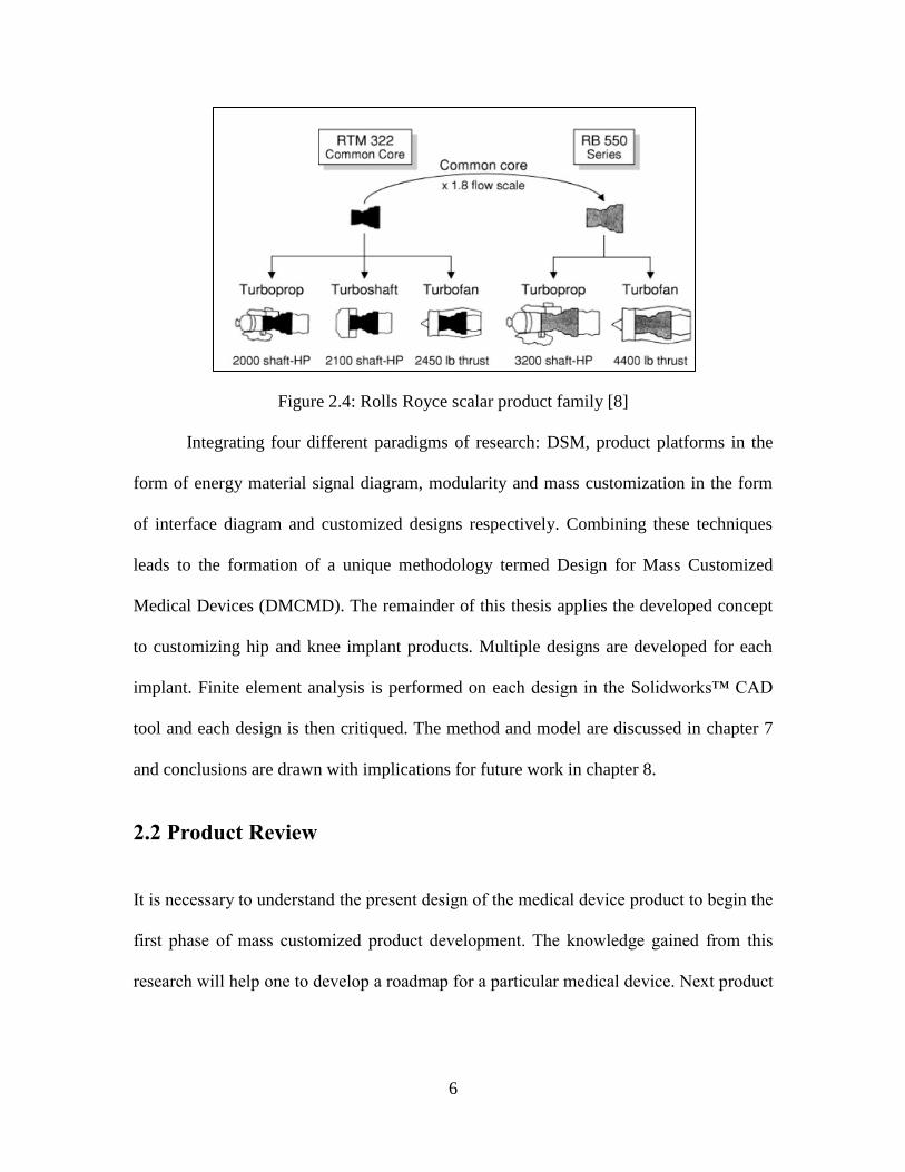
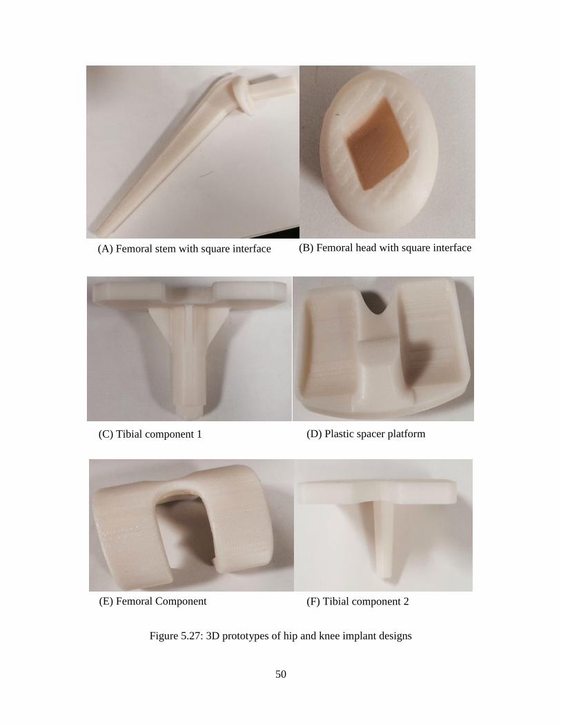
5.5 Hip and Knee Implant Products Rapid Prototyping
Developed designs were converted to stl files in Solidworks™ software for 3D printing
purpose. The products were 3D printed using the dimension sst1200es 3d printing
machine shown in Figure 5.26, located in the mechanical and Industrial Engineering
laboratory at Northeastern University. Dissolving method was used in printing. It took 24
hours to print the prototypes and 24 more hours for removing the dissolving support
utilized in 3d printing. 3D prototypes of the hip and knee implant products developed
utilizing this machine are as shown in Figure 5.27.

49
Figure 5.26: Dimension sst 1200es rapid prototyping machine
50
Figure 5.27: 3D prototypes of hip and knee implant designs
(A) Femoral stem with square interface (B) Femoral head with square interface
(C) Tibial component 1
(F) Tibial component 2
(D) Plastic spacer platform
(E) Femoral Component

51
Chapter 6 Finite Element Analysis of Hip
Implant
Over the past decade from November 2002 to July 2011, a total of 578 hip implants were
recalled. Issues ranging from design flaws, early failure, manufacturing issues, cracking,
and fracturing are some of the many reasons [28]. Recalls were done by well-known
medical device companies like Stryker, Zimmer and J&J Depuy. Data suggests that some
of the devices recalled were already implanted [28]. Looking at this analysis by safe
patient project organisation, it is important to test the products that have been developed
by leveraging DMCMD. In order to prove that the module scale customized hip implant
products and platforms are robust and safe, static stress analysis is performed on them.
6.1 Problem Setup: Assembly Analysis
The customized module scale hip implant products developed in chapter 3 are converted
to three dimensional finite element models. The finite element analysis is carried out
utilizing Solidworks™ Simulation tool. Direct sparse solver is utilized for the Finite
Element Analysis (FEA). In this study the same materials, contact interactions, meshing,
loading and boundary conditions are used for all the developed module scale customized
hip implant products. The present study emphasizes the variety of interfaces of the hip
implant product.

52
6.2 Material Properties
As mentioned in chapter 3 we have focused on developing a "metal-on- plastic" hip
implant products. In this study the metal material selected is Ti6Al4v. This is a
biocompatible material with very high yield strength as shown in Table 6.1[29]. The
material selected for plastic liner in this study is cross-linked high density polyethylene.
This material is used by most of the medical device companies manufacturing hip
implant products in the present market. Material properties for polyethylene are shown in
Table 6.2 [30]. The acetabular cup, the femoral head and the femoral stem are considered
to be made of Ti6Al4v in the analysis.
Tensile strength, ultimate 138000 psi
Tensile strength, yield 128000 psi
Modulus of elasticity 16510 ksi
Density 0.160 lb/in³
Poisson's ratio 0.342
Table 6.1: Material Properties of Ti6Al4v
Tensile strength, ultimate 1450 - 6240 psi
Tensile strength, yield 1600 - 6240 psi
Modulus of elasticity 81.9-218 ksi
Density 0.0356 lb/in^3
Poisson's ratio 0.46
Table 6.2: Material Properties of Cross-Linked High Density Polyethylene

53
6.3 Contact Interactions
This finite element model study has a total of 4 contact sets. Similar to the original hip
implant product, the plastic liner is attached with the acetabular cup. The acetabular cup
and the plastic liner are attached in the analysis with two separate bonded contact sets
between them. Between the femoral head and plastic liner, there is free movement so the
contact set selected between them has no penetration. Lastly in between the femoral stem
and femoral head the contact set is kept as bonded to exactly replicate the scenario of hip
implant in the body. All 4 contact sets are shown in Figure 6.1.
Figure 6.1: Contact sets for FEA of hip implant products
(C) No penetration between head and liner (D) Bonded contact head and stem
(A) Bonded contact 1 cup and liner (B) Bonded contact 2 cup and liner

54
6.4 Loading and Boundary Conditions
According to the survey by the statistic brain website, the average male weight is 194.7
lbs [31]. The weight of the patient in our study is selected to be 250lbs, which is 50 lbs
above the average male weight, equivalent to the force of 1112 N as shown in Figure
6.2(A). This force is applied axially on the acetabular cup considering that the patient is
standing and immobile as shown in the X-ray image in Figure 6.2(B) [32]. The X-ray
image of the hip implant inside the body as shown in Figure 6.2(B); it demonstrates that
the femoral stem is fixed inside the body, thus the stem is fixed in the analysis.
Figure 6.2: Loading and boundary conditions for hip implant stress analysis
6.5 Meshing
Mesh for the hip implant product is automatically generated utilizing the Solidworks™
simulation tool. As demonstrated in Figure 6.3 the hip implant product has a complex
geometry hence the curvature based meshing is utilized from the simulation tool.
(A) Loading and boundary conditions for hip implant FEA (B) X-ray of hip implant

55
Minimum and maximum element sizes of the mesh are 0.069 inches and 0.347 inches
respectively. There are a minimum number of 8 elements in the mesh circle. The element
size growth ratio is considered as 1.2.
Figure 6.3: Module scale hip implant mesh
6.6 Stress Analysis Results
6.6.1 Hip Implant with Circular Interface
As shown in Figure 6.4, the maximum stress 1,149.9 psi is seen at the interface that has
been developed and it is very minimal, since the yield stress of the Ti6Al4v material is
128000 psi. Judging from these results the module scale customized product 1 can be said
to be strong.

56
Figure 6.4: FEA of customized hip product with circular interface
6.6.2 Hip Implant with Square Interface
As shown in Figure 6.5 the maximum stress 2373.1 psi is again seen at the interface that
has been developed. It is very minimal but a little more than the implant with the circular
interface, since the yield stress of the Ti6Al4v material is 128000 psi. Observing these
results the module scale customized product 2 can also be said to be strong.
Figure 6.5: FEA of customized hip product with square interface

57
6.6.3 Hip Implant with Elliptical Interface
As shown in Figure 6.6 the maximum stress 3119.4 psi is again seen at the interface that
has been developed. This is also much low, since the yield stress of the Ti6Al4v material
is 128000 psi. Observing these results the module scale customized product 3 can also be
said to be strong.
Figure 6.6: FEA of customized hip product with elliptical interface
Comparing the results of the three different interfaces we conclude that the circular
interface is the strongest, the square interface is somewhat less so, and the elliptical
interface is the weakest of all these. However as demonstrated, all of them are certainly
strong enough for implanting purposes. In the design phase it is proposed that the module
scale hip implant product would have a locking mechanism. Therefore because the
circular interface could not be locked, it is recommended to select the square interface in
the product development phase.

58
6.7 Displacement Results
6.7.1 Hip Implant with Circular Interface
As shown in Figure 6.7 the maximum displacement is seen at the acetabular cup. The
displacement value is very small for the force of 1100 N. Thus, it can be concluded that
the hip implant customized product is safe and not prone to dislocation in the patient’s
body under heavy loading conditions.
Figure 6.7: Displacement of customized hip product with circular interface
6.7.2 Hip Implant with Square Interface
As shown in Figure 6.8 the maximum displacement again is seen at the acetabular cup.
The displacement value is very small for the force of 1100 N. Thus, it can be concluded
that the hip implant customized product is safe and not prone to dislocation in the
patient’s body under heavy loading conditions.

59
Figure 6.8: Displacement of customized hip product with square interface
6.7.3 Hip Implant with Elliptical Interface
As shown in Figure 6.9 the maximum displacement is seen inside the acetabular cup. The
displacement value is very small for the force of 1100 N. Thus, it can be concluded that
the hip implant customized product is safe and not prone to dislocation in the patient’s
body under heavy loading conditions.

60
Figure 6.9: Displacement of customized hip product with elliptical interface
Examining the results of 3 different interfaces it can be concluded that the acetabular cup
with circular interface stem is the least prone to dislocation, the cup with elliptical
interface stem somewhat more so, and the cup with square interface stem is most likely to
dislocate among all of the 3 stem interfaces. However as demonstrated, all of them are
showing very minute displacement for heavy loading conditions, therefore they are good
enough for implanting purposes. In the design phase it is proposed that the module scale
hip implant product would have a locking mechanism. Therefore because the circular
interface could not be locked, it is recommended to select the elliptical interface in the
product development phase. The result provides a different selection compared to stress
analysis.

61
6.8 Factor of Safety Results
6.8.1 Hip Implant with Circular Interface
Observing the factor of safety results as shown in Figure 6.10, the hip implant with
circular interfaced stem can be said to be safe. It can be noticed that there are few green
colored area in the results but still the overall design can be considered safe for
implanting.
Figure 6.10: Factor of safety of customized hip product with circular interface
6.8.2 Hip Implant with Square Interface
Observing the factor of safety results as shown in Figure 6.11, the hip implant with

62
square interfaced stem can also be said to be safe. It can be noticed that there are few
green colored and few blue colored at the bottom end of the femoral stem in the results,
but still, the overall design can be considered safe for implanting.
Figure 6.11: Factor of safety of customized hip product with square interface
6.8.3 Hip Implant with Elliptical Interface
Observing the factor of safety results as shown in Figure 6.12, the hip implant with
circular interfaced stem can also be said to be safe. It can be noticed that there are few
green colored and few blue colored at the bottom end of the femoral stem in the results, a
little less than the square interfaced stem. The overall design can be considered safe for
implanting.

63
Figure 6.12: Factor of safety of customized hip product with elliptical interface
Observing the results of the customized implants with 3 different interfaces, it is seen that
the results of the products are very similar to each other. Thus, it can be concluded that
all the developed hip implant products are safe for implanting purpose.

64
Chapter 7 Finite Element Analysis of Knee
Implant
Over the past decade from February 2003 to May 2013, a total of 709 Knee implants
were recalled. Issues ranging from faulty design, early wear and delamination, difficulty
with plastic spacer inserts and manufacturing issues are some of the many reasons [33].
The issues as noticed are different from those of the hip implant described above. Recalls
were done by companies well-known in medical device industry like Stryker, Zimmer,
and J&J Depuy; the same companies that manufacture hip implants. Data suggest that
some of the devices recalled were already implanted, a situation similar to that of hip
implants discussed above. Looking at this analysis by safe patient project organization, it
is important to test the products that have been developed by leveraging DMCMD. In
order to prove that the modular customized knee implant products and platforms are
robust and safe, static stress analysis is performed on the designed products.
7.1 Problem Setup: Assembly Analysis
The modular customized knee implant products developed in chapter 4 are converted to
three dimensional finite element models. The finite element analysis is carried out in
Solidworks™ Simulation. Direct sparse solver is utilized for the Finite Element Analysis
(FEA). In this study the same materials, contact interactions, meshing, loading and
boundary conditions are used for all the developed modular customized knee implant
products. There are 8 different products designed, however testing of only 4 different
modular customized products is done to prove the design is flawless. It was felt that if all

65
four designs tested were successful, it could be assumed that the remainder would also
meet the standards. Our study is concentrated on the developed modular customized
products of the knee implant rather than the interfaces as was the case in the hip implant
stress analysis.
7.2 Material Properties
As mentioned in chapter 4 we have focused on developing "metal-on-plastic" knee
implant products. In this study the metal material selected is Ti6Al4v. This is a
biocompatible material with very high yield strength as shown in Table 6.1. The material
selected for plastic spacer in this study is cross-linked high density polyethylene .This
material is used in manufacturing by most of the medical device companies developing
knee implant products in the present market. Material properties for polyethylene are
shown in Table 6.2. The femoral component and the tibial component are considered to
be made of Ti6Al4v in the analysis.
7.3 Contact Interactions
This finite element model study has a total of 4 contact sets. Similar to the original knee
implant product the plastic spacer is attached to the tibial component. The plastic spacer
and the tibial component are bonded together in this analysis with 3 different bonded
contact sets. Between the femoral component and the plastic spacer there is free
movement so the contact set selected between them has no penetration, to exactly
replicate the scenario of knee implant in the body. All 4 contact sets are shown in Figure
7.1.

66
Figure 7.1: Contact sets for FEA of knee implant products
7.4 Loading and Boundary Conditions
The weight of the patient in this study is selected to be 250lbs, which is 50 lbs above the
average male weight, equivalent to the force of 1112 N as shown in Figure 7.2(A).The
force is applied axially on the femoral component assuming that the patient is standing
and immobile as shown in the X-ray image in Figure 7.2(B) [34]. The X-ray image of the
knee implant inside the body as shown in Figure 7.2(B), demonstrated that the tibial
component is fixed inside the body. Thus the tibial component is fixed in the analysis.
(A) Bonded contact 1 tibial and spacer (B) Bonded contact 2 tibial and spacer
(C) Bonded contact 3 tibial and spacer (D) No penetration between femoral and spacer

67
Figure 7.2: Loading and boundary conditions for knee implant stress analysis
7.5 Meshing
Mesh for the knee implant product is automatically generated utilizing the Solidworks™
simulation tool. As demonstrated in Figure 7.3, the knee implant product also has a
complex geometry similar to the hip implant, hence the curvature based meshing is
utilized from the simulation tool. Minimum and maximum element sizes of the mesh are
0.069 inches and 0.347 inches respectively. There are a minimum number of 8 elements
in the mesh circle. The element size growth ratio is considered as 1.2.
(A) Loading and boundary conditions for knee implant FEA (B) X-ray of knee implant

68
Figure 7.3: Modular knee implant mesh
7.6 Results
7.6.1 Knee Implant customized products stress analysis
FEA results of the knee implant products can be observed in the Figure 7.4. Product 4 is
the strongest while Product 5 is the least strong among all four products. Stress value of
the rest of the 8 products is in between the range of Product 4 and 5 in terms of stress as
observed in the results of stress analysis. All the products are strong enough for the
purpose of implanting since the highest stress among all 8 products is just 626.235 psi,
which is substantially low compared to the yield stress of Ti6Al4v, which is 128000 psi.

69
Product 1: Femoral component 1,
Tibial component 1 and platform 1
Product 2: Femoral component 2,
Tibial component 1 and platform 1
Product 3: Femoral component 1,
Tibial component 1 and platform 2
Product 4: Femoral component 2,
Tibial component 1 and platform 2

70
Figure 7.4: FEA of modular customized knee products
Product 5: Femoral component 1,
Tibial component 2 and platform 2
Product 6: Femoral component 2,
Tibial component 2 and platform 2
Product 7: Femoral component 1,
Tibial component 2 and platform 1
Product 8: Femoral component 2,
Tibial component 2 and platform 1

71
7.6.2 Knee Implant customized products FEA displacement
Displacement results of the knee implant products can be observed in the Figure 7.5.
Examining the results, Product 3 shows the maximum displacement while product 4
shows the least among all eight products. Displacement results of the remainder of the 8
products are in between the range of product 3 and 4 in terms of displacement as
observed in the results of the FEA displacement. All the products are good enough for the
purpose of implanting since the highest displacement among all 8 products is .000729
inches which is very minimal. The product will surely not dislocate inside the patient’s
body.
Product 1: Femoral component 1,
Tibial component 1 and platform 1
Product 2: Femoral component 2,
Tibial component 1 and platform 1

72
Product 3: Femoral component 1,
Tibial component 1 and platform 2
Product 4: Femoral component 2,
Tibial component 1 and platform 2
Product 5: Femoral component 1,
Tibial component 2 and platform 2
Product 6: Femoral component 2,
Tibial component 2 and platform 2

73
Figure 7.5: Displacement of modular customized knee products
7.6.3 Knee Implant customized products FEA Factor of Safety
Factor of safety results for the customized knee implant products are as shown in Figure
7.6. The results show that all the customized products are fully safe. Product 2 is the
safest while product for the least safe among the 8 knee product results. These results
verify and validate that the designed customized knee are safe for implanting purpose.
Product 7: Femoral component 1,
Tibial component 2 and platform 1
Product 8: Femoral component 2,
Tibial component 2 and platform 1

74
Product 1: Femoral component 1,
Tibial component 1 and platform 1
Product 3: Femoral component 1,
Tibial component 1 and platform 2
Product 2: Femoral component 2,
Tibial component 1 and platform 1
Product 4: Femoral component 2,
Tibial component 1 and platform 2

75
Figure 7.6: Factor of safety of modular customized knee products
Product 5: Femoral component 1,
Tibial component 2 and platform 2
Product 6: Femoral component 2,
Tibial component 2 and platform 2
Product 7: Femoral component 1,
Tibial component 2 and platform 1
Product 8: Femoral component 2,
Tibial component 2 and platform 1

76
Chapter 8 Discussion and Conclusion
8.1 Discussion
As pointed out in the previous chapters, a combination of techniques from the fields of
management and engineering has been recommended to develop a new methodology
termed as DMCMD. It is then applied on two of the most common implanted medical
devices, the hip implant and the knee implant. Figure 8.1 shows various operation phases
of the DMCMD method.
After defining and reviewing the medical device product a specific type of product is
selected, which is further customized utilizing product platform methodology. The use of
DSM was fruitful in understanding various connections between the components of the
hip and the knee implant products. Overall, as seen in Figure 3.2 and 4.3 both systems are
not complex. But, this planned methodology would be very useful when implemented on
a more complex medical device. In future research, the plan is to apply this methodology
to more complex devices like artificial hearts and other complex implants.
Figure 8.1: Operation phases in DMCMD method

77
In the next phase, the EMS diagram was developed. This helped in deconstructing the hip
and knee implant products in order to understand the connections between various
components. In addition the mass customized component was identified using the EMS
diagram. Three different platforms were proposed for the hip and the knee implants. The
EMS diagram was leveraged to develop an interface diagram. From this, an interface
with a better locking mechanism between the femoral stem and femoral head was created
in the case of hip implant. In the case of the knee implant there were two interfaces
proposed. The interface number 1 consisted of the circular taper while the interface
number 2 was designed with the keyway on the taper to provide a locking mechanism
between the plastic spacer and the tibial component. Then a module scale platform was
developed for the hip implant and a modular platform developed for the knee implant.
Utilizing the platforms designed, a family of products was created both for the hip and
the knee implant. A benefit of this process is the identification of a mass customized
element or platform. This allows the product development team to focus on increasing the
robustness and quality of the engineering within those parts and developing numerous
products out of them. Further research on more non-toxic material and/or a material
subject to less wear and tear are the logical next steps in improving the design.
Lastly, we used Solidworks™ to develop a 3D model of the implant products with
various mass customized modular and scalar platforms for the hip and the knee implant
that could easily be customized based on the individual needs. Going further, the design
was validated by making a prototype of the implant using a 3D printer. Digital design and
rapid prototyping are increasingly being used to design and manufacture custom medical
devices, not only for external uses, but also for internal devices such as skull fragments

78
and dental implants. We view the inclusion of digital design and prototyping directly into
the process, as essential in developing high variety and low cost mass customized
devices. Finally, finite element analysis was performed on various products of the
customized hip and knee implants. Then various different products were compared to find
the best possible product among them.
8.2 Conclusion
In this thesis we have demonstrated the use of product platform, modularization and mass
customization on the hip and knee implant products. We applied DSM on hip and knee
implants to simplify the complexity of the devices. Furthermore, we used an EMS
diagram to procure platform elements. The mass customized component was found using
EMS. We then developed an interface diagram to obtain various interfaces for both the
hip and the knee implant. Solidworks™ CAD was employed to develop a 3D model of
the mass customized implant assembly, resulting in a well-defined interface for the mass
customized component. In summary the DMCMD method applied on the implant
examples demonstrate an amalgamation of tools like the DSM, product platform and
mass customization can be employed with efficacy in healthcare. The stress analysis
results prove that the family of products created using DMCMD are strong enough for
implanting purpose
Future work includes conducting cost benefit analysis on mass customizable medical
devices that encompasses platform-based modular and/or scalar architecture. It will help
us understand the actual impact of mass customization and the product platform
methodologies. DMCMD will also be implemented on more complex medical devices

79
and to expand its use in various other areas of healthcare to ensure its effectiveness.
Further market segmentation can be used to modularize the platform based on various
market niches for a particular product or device. Individualized medical devices can be
developed by applying the shape commonalization technique on the X-ray images of
multiple patients. A macro can be developed to find commonality indices from the
patients X-ray images using which one can propose a tailor made medical device for a
specific patient group type. The designs can then be developed in Solidworks™ which
can be converted to stl files for developing a product using rapid prototyping.

80
References
1. Is The Product A Medical Device?, Food and Drug Administration(FDA),10 June
2014. Available online at: http://www.fda.gov/medicaldevices/deviceregulation
andguidance/overview/classifyyourdevice/ucm051512.htm (accessed 6 July
2014).
2. Learn if a Has Been Cleared by FDA for Marketing, Food and Drug Administration
(FDA), 4 June 2014. Available online at: http://www.fda.gov/medicaldevices/
resourcesforyou/consumers/ucm142523 .htm (accessed 6 July 2014).
3. Dalgarno, K. W., Pallari, J. H., Woodburn, J., Xiao, K., Wood, D. J., Goodridge, R.
D., and Ohtsuki, C., Mass customization of medical devices and implants: state
of the art and future directions. Virtual and Physical Prototyping, 2006, 1(3),
137-145.
4. Marion, T. J., Freyer, M., Simpson, T. W., and Wysk, R. A., Design for mass
customization in the early stages of product development. ASME 2006
International Design Engineering Technical Conferences and Computers and
Information in Engineering Conference, ASME, 2006, Paper no.
DETC2006/DFLMC-99641.
5. Robertson, D. and K. Ulrich , Planning for product platforms. Sloan management
review, 1998, 39(4).
6. Product Architecture and Platforms, University of California, Berkeley. Available
online at: http://best.berkeley.edu/~aagogino/Slides/11_SPD_platforms.pdf,
(accessed 26 May 2014).

81
7. Sanderson, S. and M. Uzumeri, Managing product families: The case of the Sony
Walkman. Research policy, 1995, 24(5), 761-782.
8. Simpson, T. W., Siddique, Z., and Jiao, J. R., Platform-based product family
development. Product platform and product family design, Springer US, 2006,
1-15.
9. Simpson, T. W., Product Platform Design and Customization: Status and Promise.
Artificial Intelligence for Engineering Design, Analysis and Manufacturing,
2004, 18(1), 3-20.
10. Meyer, M. H. and Lehnerd, A. P., The Power of Product Platforms: Building Value
and Cost Leadership, 1997 (The FreePress: New York).
11. Sharman, D.M. and Yassine, A.A., Characterizing Complex Product Architectures.
Systems Engineering , 2004, 7(1), 35-60.
12. Jose, A. and Tollenaere, M., Modular and Platform Methods for Product Family
Design Literature Analysis. Journal of Intelligent Manufacturing, 2005, 16(3),
371-390.
13. Lindemann, U., The Design Structure Matrix. Institute of Product Development:
Garching/Munich, Germany, 2009; Available online at:
http://www.dsmweb.org (accessed 1st February 2013).
14. Chen, C.H., Ling, S.F. and Chen, W., Project Scheduling for Collaborative Product
Development using DSM. International Journal of Project Management, 2003,
21(4), 291-299.

82
15. Browning, T.R., Applying the Design Structure Matrix to System Decomposition
and Integration Problems: A Review and New Directions. IEEE Transaction on
Engineering Management, 2001, 48(3), 292-306.
16. Pimmler, T. U., and Eppinger, S. D.,Integration analysis of product decompositions.
Alfred P. Sloan School of Management, Massachusetts Institute of Technology:
Cambridge, MA, 1994, 343-351.
17. Fujimoto, T., Noryokukochikukyoso (Capability-building competition), hukousinsyo
(in Japanese). English translation: Competing to be really, really good
(translated by Miller, Brian), International House of Japan, Tokyo, 2003.
18. Ogot, M., EMS Models: Adaptation of Engineering Design Black-box Modeling for
Use in TRIZ. European TRIZ Association World Conference, TRIZ Future,
Florence, Italy, 2004.
19. Mikkola, J. H., Product Architecture Design: Implications for Modularization and
Interface Management, LINK Workshop, Copenhagen Business School,
Denmark, 2000.
20. Anderson, D. M. and Pine, B. J., II, Agile Product Development for Mass
Customization. Irwin, Chicago, IL, 1997.
21. Hips, Hartzband Center for Hip and Knee Replacement, 2006. Available online at:
www.hartzbandjoints.com/hips.htm (accessed 22 February 2013).
22. Types of Hip Replacement and Methods of Fixation, Joint Replacement Institute,
2012. Available online at: http://www.jridocs.com/HIP/HIPREPLACEMENT
/RESOURCES/Pages/TypesofHipReplacementandMethodsofFixation.aspx
(accessed 22 February 2013).

83
23. Unit 6-The Hip, Virginia Commonwealth University. Available online at:
http://www.courses.vcu.edu/DANC291003/unit_6.htm (accessed 7 April 2013).
24. Total Knee Replacement, OrthoInfo, 2011. Available online at: http://orthoinfo
.aaos.org/topic.cfm?topic=a00389 (accessed 7 June 2014).
25. Knee Replacement Implants, OrthoInfo, 2011. Available online at: http://orthoinfo
.aaos.org/topic.cfm?topic=A00221 (accessed 7 June 2014).
26. Kneecap Replacement, Arthritis Research UK, 2013. Available online at:
http://www.arthritisresearchuk.org/arthritis-information/surgery/knee-
replacement/different-types/kneecap-replacement.aspx (accessed 12 June 2014).
27. Agarwal, S., Knee Replacement Surgery, Cardiff Hip and Knee. Available online at:
http://cardiffhipandknee.com/id2.html (accessed 15 June 2014).
28. Henry, S., A Summary of Hip Implant Recalls Safe Patient Project, Consumers
Union, 9 September 2013. Available online at: http://safepatientproject.org/
wordpress/wp-content/uploads/2013/09/Hip-Recalls-Summary-Final-9-9-
131.pdf (accessed 17 June 2014).
29. Titanium Ti-6Al-4V(Grade 5, Annealed), MatWeb, 2014. Available online at:
http://www.matweb.com/search/DataSheet.aspx?MatGUID=a0655d261898456
b958e5f825ae85390&ckck=1 (accessed 12 April 2014).
30. High Density Polyethelene ( Injection Molded), MatWeb, 2014. Available online at:
http://www.matweb.com/search/datasheet.aspx?MatGUID=fce23f90005d4fbe8e
12a1bce53ebdc8 (accessed 12 April 2014).
31. Human Body Statistics, Statistic Brain, 14 July 2014. Available online at:
http://www.statisticbrain.com/human-body-statistics/ (accessed 16 July 2014).

84
32. Rajagopalan, B., Hip Treatment, Dr. Hip and Knee,2014. Available online at:
http://www.drhipandknee.com/wp- content/uploads/2013/08/canstockphoto
130929101.jpg (accessed 12 June 2014).
33. Henry, S., A Summary of Knee Implant Recalls Safe Patient Project, Consumers
Union, 9 September 2013. Available online at: http://safepatientproject.org/
wordpress/wp-content/uploads/2013/09/Knee-Recall-Summary-Final-9-9-
13.pdf (accessed 15 June 2014).
34. Matthys, G., Revision Knee Replacement, Matthys Orthopaedics, 2011. Available
online at: http://www.jointpain.md/Procedures/KneeRevision.aspx (accessed 15
June 2014).

85
Appendix: Hip implant analysis for different
materials
Just out of curiosity, FEA was done on hip implant module scale products with three
different types of materials. The three material considered in stress analysis were
Ti6Al4v, Titanium Grade 4 and Stainless steel. The results obtained are compared in
terms of materials in this appendix.
Comparing the results for hip with circular interface, it is observed from stress analysis
that the hip product with Ti6Al4v material is the strongest while, the product with
stainless steel is the least strong with titanium grade 4 hip product in between both of
them. There is not a significant difference between the results as shown in Figure A.1.
(A) Hip material Ti6Al4v (B) Hip material stainless steel

86
Figure A.1: Different material FEA results of hip product with circular interface
(C) Hip material titanium
grade 4
(A) Hip material Ti6Al4v (B) Hip material stainless steel

87
Figure A.2: Different material FEA results of hip product with elliptical interface
Comparing the results for hip with elliptical interface, it is again observed from stress
analysis that the hip product with Ti6Al4v material is the strongest while, the product
with stainless steel is the least strong with titanium grade 4 hip product in between both
of them. There is not a significant difference between the results as shown in Figure A.2.
(C) Hip material titanium grade 4

88
Figure A.3: Different material FEA results of hip product with square interface
(A) Hip material Ti6Al4v (B) Hip material stainless steel
(C) Hip material titanium grade 4

89
Comparing the results for hip with square interface, it is again observed from stress
analysis that the hip product with Ti6Al4v material is the strongest while, the product
with stainless steel is the least strong with titanium grade 4 hip product in between both
of them. There is not a significant difference between the results as shown in Figure A.3.