design audits of machinery: rotor dynamics
15
D ESIGN A UDITS OF MACHINERY: R OTOR D YNAMICS C. Hunter Cloud Turbomachinery’s overall reliability depends heavily on its underlying rotordynamic character- istics. This tutorial briefly reviews some of the important rotordynamic principles and phenom- ena. Case history examples are presented illustrating the influence of operating conditions on machinery vibration performance. Presented at: Twenty-First Ethylene Producers’ Conference AIChE Spring National Meeting April 2009 Tampa, Florida Published in: Proceedings of the Twenty-First Ethylene Producers’ Conference EPC–143761, Vol. 1, 2009 BRG Machinery Consulting, LLC 703 Highland Avenue Charlottesville, Virginia 22903 USA Phone\Fax: (434) 293–9926 www.BRGmachinery.com
Transcript of design audits of machinery: rotor dynamics
DESIGN AUDITS OF MACHINERY:
ROTOR DYNAMICS
C. Hunter Cloud
Turbomachinery’s overall reliability depends heavily on its underlying rotordynamic character-istics. This tutorial briefly reviews some of the important rotordynamic principles and phenom-ena. Case history examples are presented illustrating the influence of operating conditions onmachinery vibration performance.
Presented at:Twenty-First Ethylene Producers’ Conference
AIChE Spring National MeetingApril 2009
Tampa, Florida
Published in:Proceedings of the Twenty-FirstEthylene Producers’ Conference
EPC–143761, Vol. 1, 2009
BRG Machinery Consulting, LLC703 Highland Avenue
Charlottesville, Virginia 22903 USAPhone\Fax: (434) 293–9926
www.BRGmachinery.com
Design Audits of Machinery–Rotor Dynamics
1 Introduction
The costs associated with critical machinery downtime in ethylene and other petrochemical plants continueto increase. While machinery OEMs may guarantee their hardware, they do not guarantee these downtimelosses in the event the machine does not work reliably over the expected life. Therefore, the end-user bearssubstantially greater costs and is the one most concerned with minimizing risks. To mitigate the risks ofsuch machinery downtime, there are many types of machinery design audits that can be performed: aero-dynamic and thermodynamic performance, blade and impeller stresses, auxiliary system sizing, couplingsizing and rotordynamic performance [2].
The fundamental objective of all such audits is to identify problems before manufacturing to avoiddelays during shop testing and downtime in the field. If a rotordynamic problem is encountered aftermanufacturing begins, the end-user may have to deal with delays in machine delivery. If the problem isnot identified until after field commissioning, the implications include reduced production due to restrictedoperating range (speed, pressure, power, flow, etc.), poor long term reliability/performance reducing timebetween outages, or even failure threatening life and environment.
Given these implications, it is important to perform rotordynamics audits for not only new machinesbut also for any modification of existing machines in critical applications. Debottlenecking projects thatmay involve gas composition or speed changes can adversely affect a machine’s rotordynamics just as muchas a bearing, seal or coupling design upgrade.
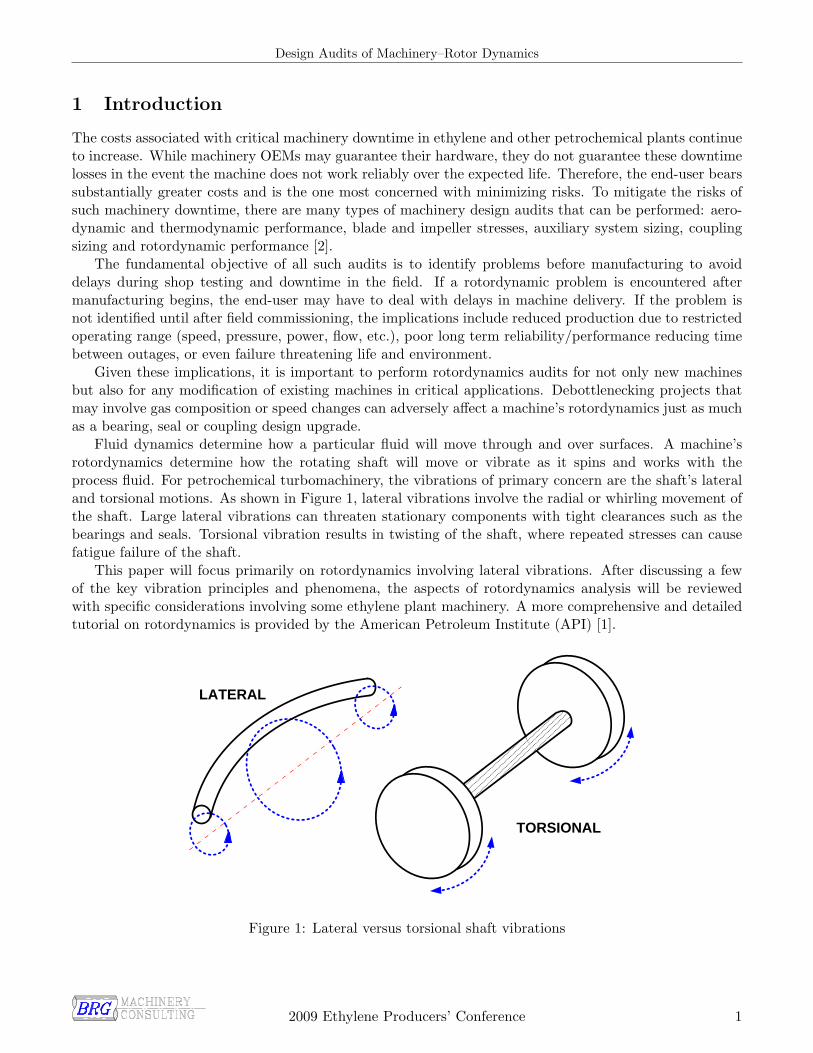
Fluid dynamics determine how a particular fluid will move through and over surfaces. A machine’srotordynamics determine how the rotating shaft will move or vibrate as it spins and works with theprocess fluid. For petrochemical turbomachinery, the vibrations of primary concern are the shaft’s lateraland torsional motions. As shown in Figure 1, lateral vibrations involve the radial or whirling movement ofthe shaft. Large lateral vibrations can threaten stationary components with tight clearances such as thebearings and seals. Torsional vibration results in twisting of the shaft, where repeated stresses can causefatigue failure of the shaft.
This paper will focus primarily on rotordynamics involving lateral vibrations. After discussing a fewof the key vibration principles and phenomena, the aspects of rotordynamics analysis will be reviewedwith specific considerations involving some ethylene plant machinery. A more comprehensive and detailedtutorial on rotordynamics is provided by the American Petroleum Institute (API) [1].
LATERAL
TORSIONAL
Figure 1: Lateral versus torsional shaft vibrations
2009 Ethylene Producers’ Conference 1
Design Audits of Machinery–Rotor Dynamics
2 Vibration Principles and Phenomena
Throughout a machine’s operating range and life (between turnarounds), maintaining small rotor vibrationamplitudes is our basic desire. Small rotor vibrations result in low stresses on the shaft, bearings andsurrounding equipment. Furthermore, when lateral vibrations are kept at low levels, machine designersare able to implement tighter seal clearances yielding better thermodynamic efficiency of the machine.Though numerous vibration phenomena threaten these benefits, two deserve the most attention, resonanceand instability.
2.1 Resonance
Resonances are a concern because small excitations can be amplified to yield very large vibrations. Strictlyspeaking, a resonance condition occurs when an excitation’s frequency nearly coincides with a systemnatural frequency. An opera singer breaking a wine glass is a classic example of resonance, where thesinger’s pitch nearly equals the natural frequency of the glass. Even though the force of the sound wavesis very small, their frequency causes large vibrations in the glass that eventually cause it to crack.
Just like wine glasses, guitar strings and tuning forks, shafts and machine structures have frequencieswhere they naturally prefer to oscillate when excited. These natural frequencies are dependent on variousproperties of the system. For a simple weight hung from a spring, its natural frequency, ωn, equals:
ωn =
√k
m
where k is the spring’s stiffness and m is the weight’s mass. A turbomachine will have many naturalfrequencies, not just one, that are also dependent on its stiffness and mass properties.
As mentioned earlier, the recipe for resonance demands not only a natural frequency, but also thepresence of an excitation source with a similar frequency. The biggest excitation source of concern withinturbomachinery is shaft unbalance. Just like an unbalanced washing machine load or an unbalanced tire,shaft unbalance occurs when the center of mass is not coincident with the center of rotation. Caused bymaterial imperfections within the shaft, manufacturing tolerances and anything that affects the rotationalmass distribution (such as fouling), unbalance can never be totally eliminated.
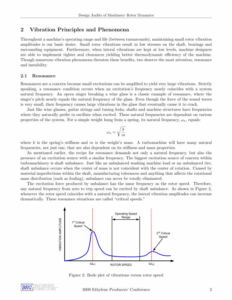
The excitation force produced by unbalance has the same frequency as the rotor speed. Therefore,any natural frequency from zero to trip speed can be excited by shaft unbalance. As shown in Figure 2,whenever the rotor speed coincides with a natural frequency, the lateral vibration amplitudes can increasedramatically. These resonance situations are called “critical speeds.”
ROTOR SPEED
VIB
RA
TIO
N A
MP
LITU
DE
Operating Speed Range
ωn1 ωn2
1st Critical Speed
2nd Critical Speed
Figure 2: Bode plot of vibrations versus rotor speed
2009 Ethylene Producers’ Conference 2

Design Audits of Machinery–Rotor Dynamics
Whether or not a critical speed will cause large vibrations is highly dependent on damping in thesystem. Adding wine to the glass makes it more difficult, if not impossible, for the singer to crack theglass. Relative to the glass material by itself, the wine has very large damping helping to decay anyvibrations quickly. The oil film within the journal bearings provides the main source of damping for manyturbomachines. However, for pumps, the main source of damping comes from the process fluid within theclose clearance wear rings.
Figure 3 shows how increasing the bearings’ damping can reduce vibrations when going through acritical speed. However, bearings have a limit to how much damping they can provide and this may not beenough to restrict critical speed vibration levels. When this is the case, the critical speed must be avoidedthrough startup procedures (quickly accelerating through it) as well as by ensuring adequate separationmargin with the operating speed range. As shown in Figure 2, the first critical speed often has less dampingthan the second critical speed. Most large compressors and turbines are designed to operate between theirfirst and second critical speeds.
Rotor Speed
Vib
ratio
nA
mpl
itude
ωnIncreasing Damping
Figure 3: Bearing damping’s influence on critical speed amplification
2.2 Instability
Resonances and critical speeds are phenomena falling into the class of forced vibration problems. Withoutthe presence of an excitation source like unbalance, the vibration would not occur. Another class ofvibration problems exists, however, which are self-induced or self-excited in nature. Self-excited impliesthat the forces causing the vibration are controlled by the vibration itself. Turbomachines can experiencethese self-excited vibrations through a phenomenon called rotor instability [4].
A common example of self-excited instability is the unpleasant squeal sometimes heard to due feedbackwithin a microphone-amplifier-speaker system. The frequency of the squeal is actually the natural frequencyof the sound system, and it is so loud because the system has no damping allowing the squeal to grownuncontrollably. Eliminating the squeal is accomplished by reducing the amount of feedback by eitherturning down the volume, moving the speakers, or using a directional microphone.
Acting just like feedback mechanisms, various components within a turbomachine produce forces whosemagnitude and direction are functions of the rotor’s motion. Their strength is often dependent on rotorspeed and the process fluid’s pressure and density. Figure 4 shows how these destabilizing mechanismsencourage vibration by acting tangential to the rotor’s whirling motion. Battling against these destabilizingforces is damping. When the damping forces are larger than the destabilizing forces, the vibrations remainstable.
2009 Ethylene Producers’ Conference 3

Design Audits of Machinery–Rotor Dynamics
PATH OF ROTOR VIBRATION
INERTIA
STIFFNESS
DAMPING
DESTABILIZING
MECHANISM
CENTRIFUGAL
FORCE
Figure 4: Forces battling over rotor stability
Figure 5 shows how rotor vibrations can grow when destabilizing forces win the battle. For this exper-iment on an actual rotor, the destabilizing mechanism could be manually turned on or off. When turnedon, the rotor vibrations grew uncontrollably to very large levels until 3.2 seconds when the mechanism wasturned off and stable vibration returned. Unfortunately, it’s difficult to simply turn off these destabilizingmechanisms on industrial turbomachines.
Time (sec)
Sha
ftD
ispl
acem
ent(
mils
)
0 1 2 3 4-3
-2
-1
0
1
2
3
Destabilizing MechanismTurned Off
Unstable Growthof Shaft Vibration
Figure 5: Vibrations of an unstable rotor
Unstable vibrations are able to reach such large levels because of the immense energy available withinthe spinning rotor. Like a flywheel which stores energy, the spinning motion of a turbomachine’s rotorcreates a large kinetic energy reservoir. The whirling vibration of the shaft is a separate reservoir that ishopefully small. Destabilizing mechanisms provide a pipeline between these two energy sources, stealingrotational energy and pumping it into whirling vibration energy [3]. When the energy injected into thewhirling vibration exceeds the energy dissipated by damping, the rotor vibrations become unstable andlarge because their source, rotational energy, is so large.
2009 Ethylene Producers’ Conference 4
Design Audits of Machinery–Rotor Dynamics
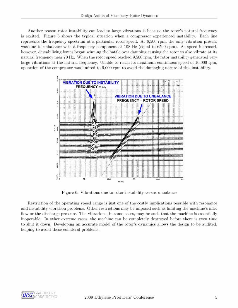
Another reason rotor instability can lead to large vibrations is because the rotor’s natural frequencyis excited. Figure 6 shows the typical situation when a compressor experienced instability. Each linerepresents the frequency spectrum at a particular rotor speed. At 6,500 rpm, the only vibration presentwas due to unbalance with a frequency component at 108 Hz (equal to 6500 cpm). As speed increased,however, destabilizing forces began winning the battle over damping causing the rotor to also vibrate at itsnatural frequency near 70 Hz. When the rotor speed reached 9,500 rpm, the rotor instability generated verylarge vibrations at the natural frequency. Unable to reach its maximum continuous speed of 10,000 rpm,operation of the compressor was limited to 9,000 rpm to avoid the damaging nature of this instability.
VIBRATION DUE TO UNBALANCEFREQUENCY = ROTOR SPEED
VIBRATION DUE TO INSTABILITYFREQUENCY ≈ ωn
Figure 6: Vibrations due to rotor instability versus unbalance
Restriction of the operating speed range is just one of the costly implications possible with resonanceand instability vibration problems. Other restrictions may be imposed such as limiting the machine’s inletflow or the discharge pressure. The vibrations, in some cases, may be such that the machine is essentiallyinoperable. In other extreme cases, the machine can be completely destroyed before there is even timeto shut it down. Developing an accurate model of the rotor’s dynamics allows the design to be audited,helping to avoid these collateral problems.
2009 Ethylene Producers’ Conference 5
Design Audits of Machinery–Rotor Dynamics
3 Rotordynamic Modeling and Auditing Aspects
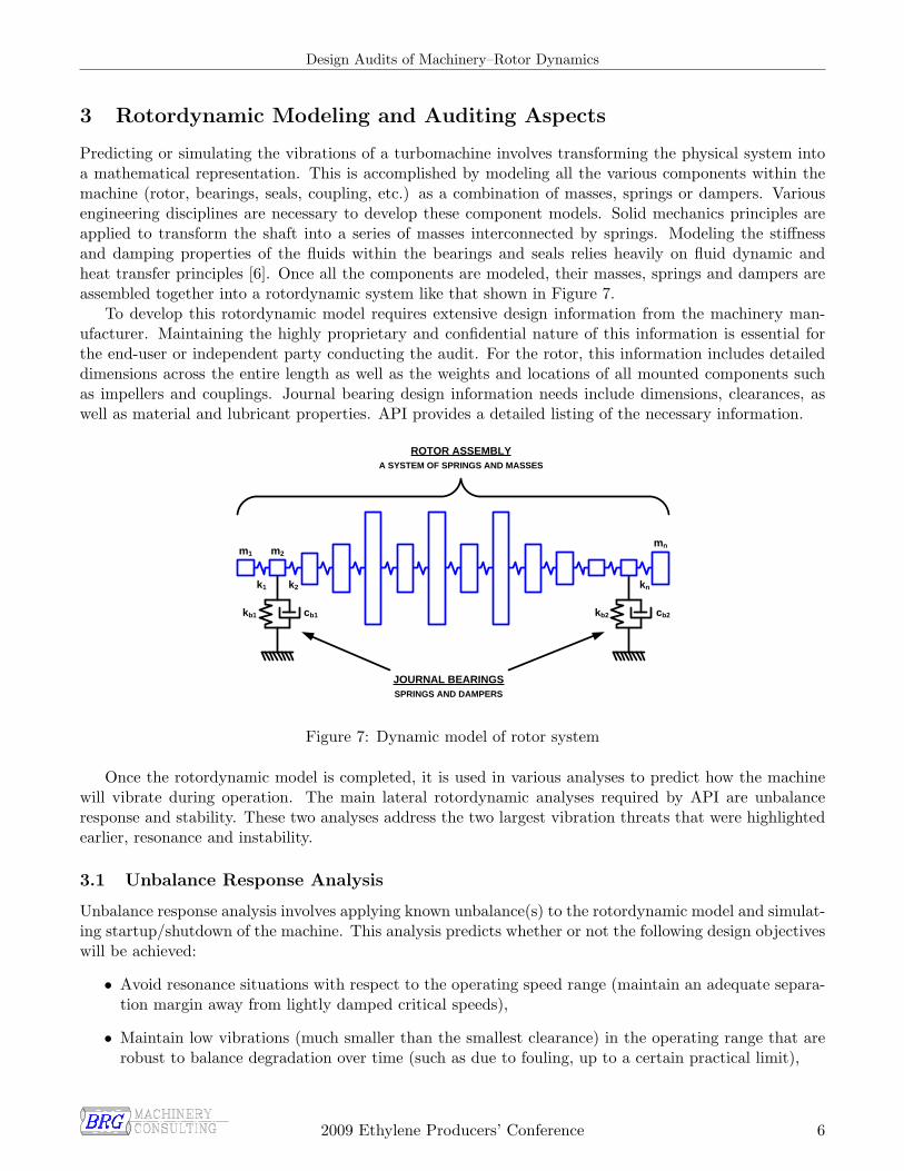
Predicting or simulating the vibrations of a turbomachine involves transforming the physical system intoa mathematical representation. This is accomplished by modeling all the various components within themachine (rotor, bearings, seals, coupling, etc.) as a combination of masses, springs or dampers. Variousengineering disciplines are necessary to develop these component models. Solid mechanics principles areapplied to transform the shaft into a series of masses interconnected by springs. Modeling the stiffnessand damping properties of the fluids within the bearings and seals relies heavily on fluid dynamic andheat transfer principles [6]. Once all the components are modeled, their masses, springs and dampers areassembled together into a rotordynamic system like that shown in Figure 7.
To develop this rotordynamic model requires extensive design information from the machinery man-ufacturer. Maintaining the highly proprietary and confidential nature of this information is essential forthe end-user or independent party conducting the audit. For the rotor, this information includes detaileddimensions across the entire length as well as the weights and locations of all mounted components suchas impellers and couplings. Journal bearing design information needs include dimensions, clearances, aswell as material and lubricant properties. API provides a detailed listing of the necessary information.
m1
k1
m2
k2
mn
kn
kb1 cb1 kb2 cb2
JOURNAL BEARINGSSPRINGS AND DAMPERS
ROTOR ASSEMBLYA SYSTEM OF SPRINGS AND MASSES
Figure 7: Dynamic model of rotor system
Once the rotordynamic model is completed, it is used in various analyses to predict how the machinewill vibrate during operation. The main lateral rotordynamic analyses required by API are unbalanceresponse and stability. These two analyses address the two largest vibration threats that were highlightedearlier, resonance and instability.
3.1 Unbalance Response Analysis
Unbalance response analysis involves applying known unbalance(s) to the rotordynamic model and simulat-ing startup/shutdown of the machine. This analysis predicts whether or not the following design objectiveswill be achieved:
• Avoid resonance situations with respect to the operating speed range (maintain an adequate separa-tion margin away from lightly damped critical speeds),
• Maintain low vibrations (much smaller than the smallest clearance) in the operating range that arerobust to balance degradation over time (such as due to fouling, up to a certain practical limit),
2009 Ethylene Producers’ Conference 6
Design Audits of Machinery–Rotor Dynamics
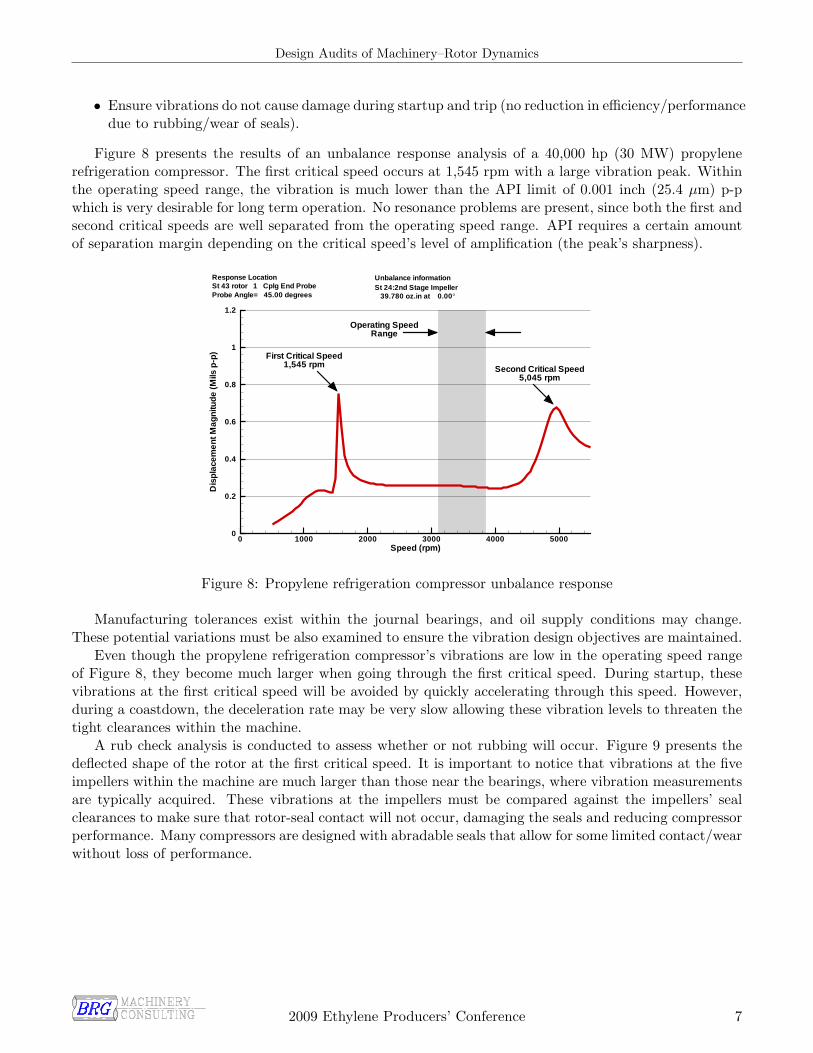
• Ensure vibrations do not cause damage during startup and trip (no reduction in efficiency/performancedue to rubbing/wear of seals).
Figure 8 presents the results of an unbalance response analysis of a 40,000 hp (30 MW) propylenerefrigeration compressor. The first critical speed occurs at 1,545 rpm with a large vibration peak. Withinthe operating speed range, the vibration is much lower than the API limit of 0.001 inch (25.4 µm) p-pwhich is very desirable for long term operation. No resonance problems are present, since both the first andsecond critical speeds are well separated from the operating speed range. API requires a certain amountof separation margin depending on the critical speed’s level of amplification (the peak’s sharpness).
First Critical Speed1,545 rpm Second Critical Speed
5,045 rpm
Operating SpeedRange
Speed (rpm)
Dis
pla
cem
entM
agni
tude
(Mils
p-p
)
0 1000 2000 3000 4000 50000
0.2
0.4
0.6
0.8
1
1.2
Unbalance informationSt 24:2nd Stage Impeller
39.780 oz.in at 0.00°Probe Angle= 45.00 degrees
Response LocationSt 43 rotor 1 Cplg End Probe
Figure 8: Propylene refrigeration compressor unbalance response
Manufacturing tolerances exist within the journal bearings, and oil supply conditions may change.These potential variations must be also examined to ensure the vibration design objectives are maintained.
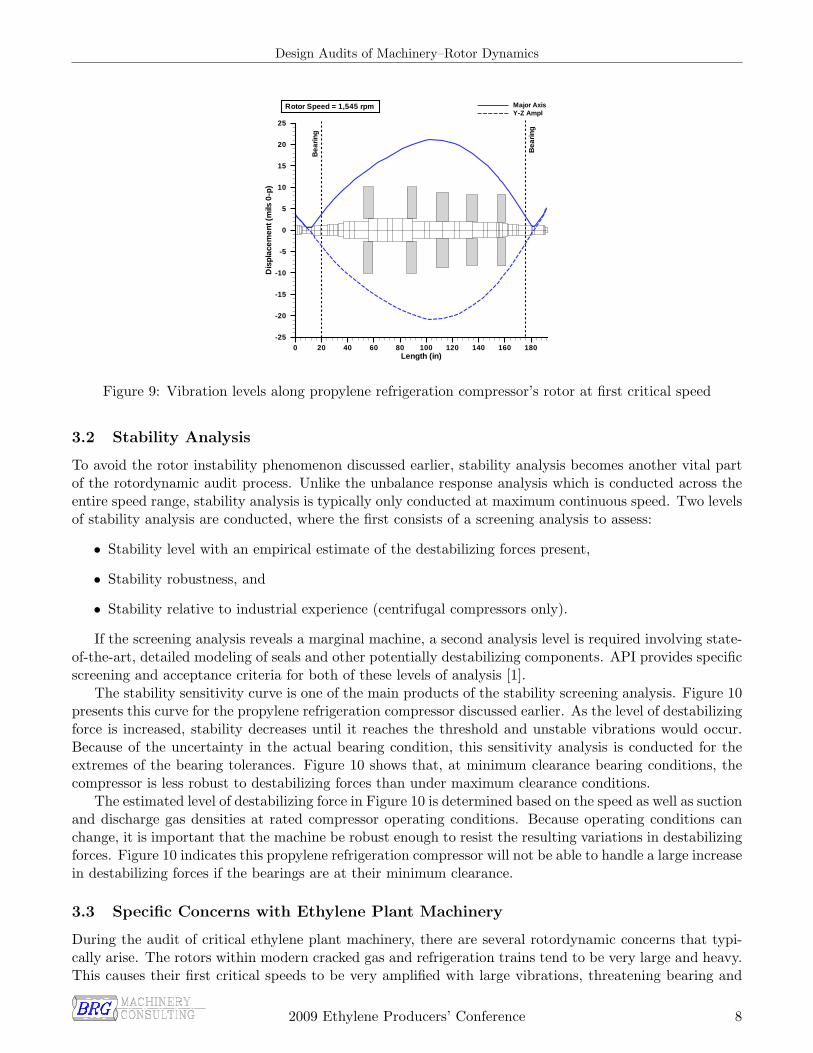
Even though the propylene refrigeration compressor’s vibrations are low in the operating speed rangeof Figure 8, they become much larger when going through the first critical speed. During startup, thesevibrations at the first critical speed will be avoided by quickly accelerating through this speed. However,during a coastdown, the deceleration rate may be very slow allowing these vibration levels to threaten thetight clearances within the machine.
A rub check analysis is conducted to assess whether or not rubbing will occur. Figure 9 presents thedeflected shape of the rotor at the first critical speed. It is important to notice that vibrations at the fiveimpellers within the machine are much larger than those near the bearings, where vibration measurementsare typically acquired. These vibrations at the impellers must be compared against the impellers’ sealclearances to make sure that rotor-seal contact will not occur, damaging the seals and reducing compressorperformance. Many compressors are designed with abradable seals that allow for some limited contact/wearwithout loss of performance.
2009 Ethylene Producers’ Conference 7
Design Audits of Machinery–Rotor Dynamics
Length (in)
Dis
pla
cem
ent(
mils
0-p
)
0 20 40 60 80 100 120 140 160 180-25
-20
-15
-10
-5
0
5
10
15
20
25
Major AxisY-Z Ampl
Rotor Speed = 1,545 rpm
Bea
ring
Bea
ring
Figure 9: Vibration levels along propylene refrigeration compressor’s rotor at first critical speed
3.2 Stability Analysis
To avoid the rotor instability phenomenon discussed earlier, stability analysis becomes another vital partof the rotordynamic audit process. Unlike the unbalance response analysis which is conducted across theentire speed range, stability analysis is typically only conducted at maximum continuous speed. Two levelsof stability analysis are conducted, where the first consists of a screening analysis to assess:
• Stability level with an empirical estimate of the destabilizing forces present,
• Stability robustness, and
• Stability relative to industrial experience (centrifugal compressors only).
If the screening analysis reveals a marginal machine, a second analysis level is required involving state-of-the-art, detailed modeling of seals and other potentially destabilizing components. API provides specificscreening and acceptance criteria for both of these levels of analysis [1].
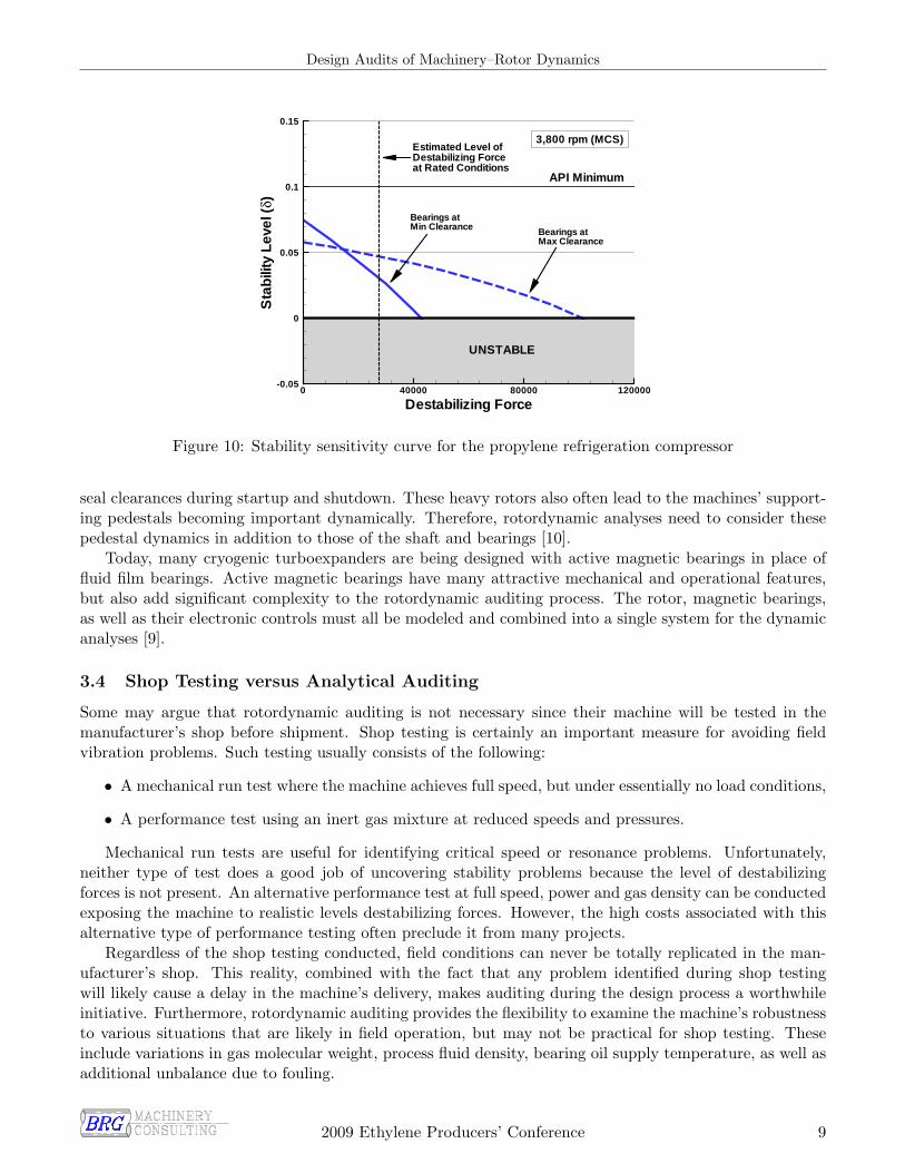
The stability sensitivity curve is one of the main products of the stability screening analysis. Figure 10presents this curve for the propylene refrigeration compressor discussed earlier. As the level of destabilizingforce is increased, stability decreases until it reaches the threshold and unstable vibrations would occur.Because of the uncertainty in the actual bearing condition, this sensitivity analysis is conducted for theextremes of the bearing tolerances. Figure 10 shows that, at minimum clearance bearing conditions, thecompressor is less robust to destabilizing forces than under maximum clearance conditions.
The estimated level of destabilizing force in Figure 10 is determined based on the speed as well as suctionand discharge gas densities at rated compressor operating conditions. Because operating conditions canchange, it is important that the machine be robust enough to resist the resulting variations in destabilizingforces. Figure 10 indicates this propylene refrigeration compressor will not be able to handle a large increasein destabilizing forces if the bearings are at their minimum clearance.
3.3 Specific Concerns with Ethylene Plant Machinery
During the audit of critical ethylene plant machinery, there are several rotordynamic concerns that typi-cally arise. The rotors within modern cracked gas and refrigeration trains tend to be very large and heavy.This causes their first critical speeds to be very amplified with large vibrations, threatening bearing and
2009 Ethylene Producers’ Conference 8
Design Audits of Machinery–Rotor Dynamics
Destabilizing Force
Sta
bili
tyL
evel
(δ)
0 40000 80000 120000-0.05
0
0.05
0.1
0.15
UNSTABLE
API Minimum
3,800 rpm (MCS)Estimated Level ofDestabilizing Forceat Rated Conditions
Bearings atMin Clearance Bearings at
Max Clearance
Figure 10: Stability sensitivity curve for the propylene refrigeration compressor
seal clearances during startup and shutdown. These heavy rotors also often lead to the machines’ support-ing pedestals becoming important dynamically. Therefore, rotordynamic analyses need to consider thesepedestal dynamics in addition to those of the shaft and bearings [10].
Today, many cryogenic turboexpanders are being designed with active magnetic bearings in place offluid film bearings. Active magnetic bearings have many attractive mechanical and operational features,but also add significant complexity to the rotordynamic auditing process. The rotor, magnetic bearings,as well as their electronic controls must all be modeled and combined into a single system for the dynamicanalyses [9].
3.4 Shop Testing versus Analytical Auditing
Some may argue that rotordynamic auditing is not necessary since their machine will be tested in themanufacturer’s shop before shipment. Shop testing is certainly an important measure for avoiding fieldvibration problems. Such testing usually consists of the following:
• A mechanical run test where the machine achieves full speed, but under essentially no load conditions,
• A performance test using an inert gas mixture at reduced speeds and pressures.
Mechanical run tests are useful for identifying critical speed or resonance problems. Unfortunately,neither type of test does a good job of uncovering stability problems because the level of destabilizingforces is not present. An alternative performance test at full speed, power and gas density can be conductedexposing the machine to realistic levels destabilizing forces. However, the high costs associated with thisalternative type of performance testing often preclude it from many projects.
Regardless of the shop testing conducted, field conditions can never be totally replicated in the man-ufacturer’s shop. This reality, combined with the fact that any problem identified during shop testingwill likely cause a delay in the machine’s delivery, makes auditing during the design process a worthwhileinitiative. Furthermore, rotordynamic auditing provides the flexibility to examine the machine’s robustnessto various situations that are likely in field operation, but may not be practical for shop testing. Theseinclude variations in gas molecular weight, process fluid density, bearing oil supply temperature, as well asadditional unbalance due to fouling.
2009 Ethylene Producers’ Conference 9
Design Audits of Machinery–Rotor Dynamics
4 Case Histories
To demonstrate some of these rotordynamic principles, several case histories will now examined. Twoof these cases illustrate how rotordynamic auditing during the design phase could have easily avoidedsubsequent vibration problems.
4.1 Cryogenic Turboexpander
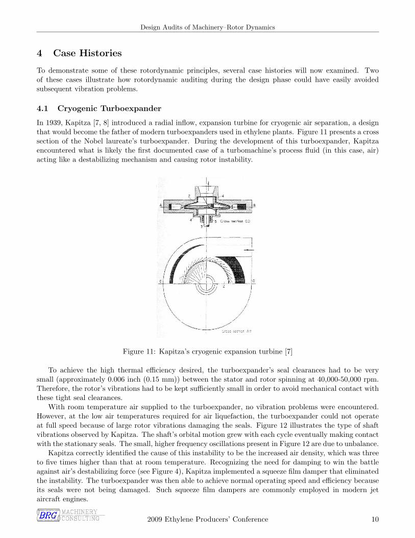
In 1939, Kapitza [7, 8] introduced a radial inflow, expansion turbine for cryogenic air separation, a designthat would become the father of modern turboexpanders used in ethylene plants. Figure 11 presents a crosssection of the Nobel laureate’s turboexpander. During the development of this turboexpander, Kapitzaencountered what is likely the first documented case of a turbomachine’s process fluid (in this case, air)acting like a destabilizing mechanism and causing rotor instability.
Figure 11: Kapitza’s cryogenic expansion turbine [7]
To achieve the high thermal efficiency desired, the turboexpander’s seal clearances had to be verysmall (approximately 0.006 inch (0.15 mm)) between the stator and rotor spinning at 40,000-50,000 rpm.Therefore, the rotor’s vibrations had to be kept sufficiently small in order to avoid mechanical contact withthese tight seal clearances.
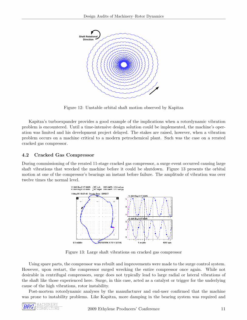
With room temperature air supplied to the turboexpander, no vibration problems were encountered.However, at the low air temperatures required for air liquefaction, the turboexpander could not operateat full speed because of large rotor vibrations damaging the seals. Figure 12 illustrates the type of shaftvibrations observed by Kapitza. The shaft’s orbital motion grew with each cycle eventually making contactwith the stationary seals. The small, higher frequency oscillations present in Figure 12 are due to unbalance.
Kapitza correctly identified the cause of this instability to be the increased air density, which was threeto five times higher than that at room temperature. Recognizing the need for damping to win the battleagainst air’s destabilizing force (see Figure 4), Kapitza implemented a squeeze film damper that eliminatedthe instability. The turboexpander was then able to achieve normal operating speed and efficiency becauseits seals were not being damaged. Such squeeze film dampers are commonly employed in modern jetaircraft engines.
2009 Ethylene Producers’ Conference 10
Design Audits of Machinery–Rotor Dynamics
Shaft RotationalDirection
Figure 12: Unstable orbital shaft motion observed by Kapitza
Kapitza’s turboexpander provides a good example of the implications when a rotordynamic vibrationproblem is encountered. Until a time-intensive design solution could be implemented, the machine’s oper-ation was limited and his development project delayed. The stakes are raised, however, when a vibrationproblem occurs on a machine critical to a modern petrochemical plant. Such was the case on a reratedcracked gas compressor.
4.2 Cracked Gas Compressor
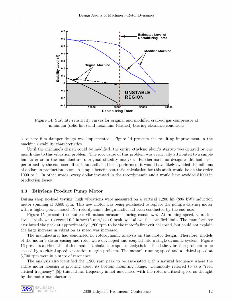
During commissioning of the rerated 11-stage cracked gas compressor, a surge event occurred causing largeshaft vibrations that wrecked the machine before it could be shutdown. Figure 13 presents the orbitalmotion at one of the compressor’s bearings an instant before failure. The amplitude of vibration was overtwelve times the normal level.
Figure 13: Large shaft vibrations on cracked gas compressor
Using spare parts, the compressor was rebuilt and improvements were made to the surge control system.However, upon restart, the compressor surged wrecking the entire compressor once again. While notdesirable in centrifugal compressors, surge does not typically lead to large radial or lateral vibrations ofthe shaft like those experienced here. Surge, in this case, acted as a catalyst or trigger for the underlyingcause of the high vibrations, rotor instability.
Post-mortem rotordynamic analyses by the manufacturer and end-user confirmed that the machinewas prone to instability problems. Like Kapitza, more damping in the bearing system was required and
2009 Ethylene Producers’ Conference 11
Design Audits of Machinery–Rotor Dynamics
Destabilizing Force
Sta
bili
tyLe
vel(
δ)
0 10000 20000 30000 40000-0.3
-0.2
-0.1
0
0.1
0.2
0.3
0.4
0.5
0.6
0.7
UNSTABLEREGION
Estimated Level ofDestabilizing Force
Original Machine
Modified Machine
Figure 14: Stability sensitivity curves for original and modified cracked gas compressor atminimum (solid line) and maximum (dashed) bearing clearance conditions
a squeeze film damper design was implemented. Figure 14 presents the resulting improvement in themachine’s stability characteristics.
Until the machine’s design could be modified, the entire ethylene plant’s startup was delayed by onemonth due to this vibration problem. The root cause of this problem was eventually attributed to a simplehuman error in the manufacturer’s original stability analysis. Furthermore, no design audit had beenperformed by the end-user. If such an audit had been performed, it would have likely avoided the millionsof dollars in production losses. A simple benefit-cost ratio calculation for this audit would be on the order1000 to 1. In other words, every dollar invested in the rotordynamic audit would have avoided $1000 inproduction losses.
4.3 Ethylene Product Pump Motor
During shop no-load testing, high vibrations were measured on a vertical 1,200 hp (895 kW) inductionmotor spinning at 3,600 rpm. This new motor was being purchased to replace the pump’s existing motorwith a higher power model. No rotordynamic design audit had been conducted by the end-user.
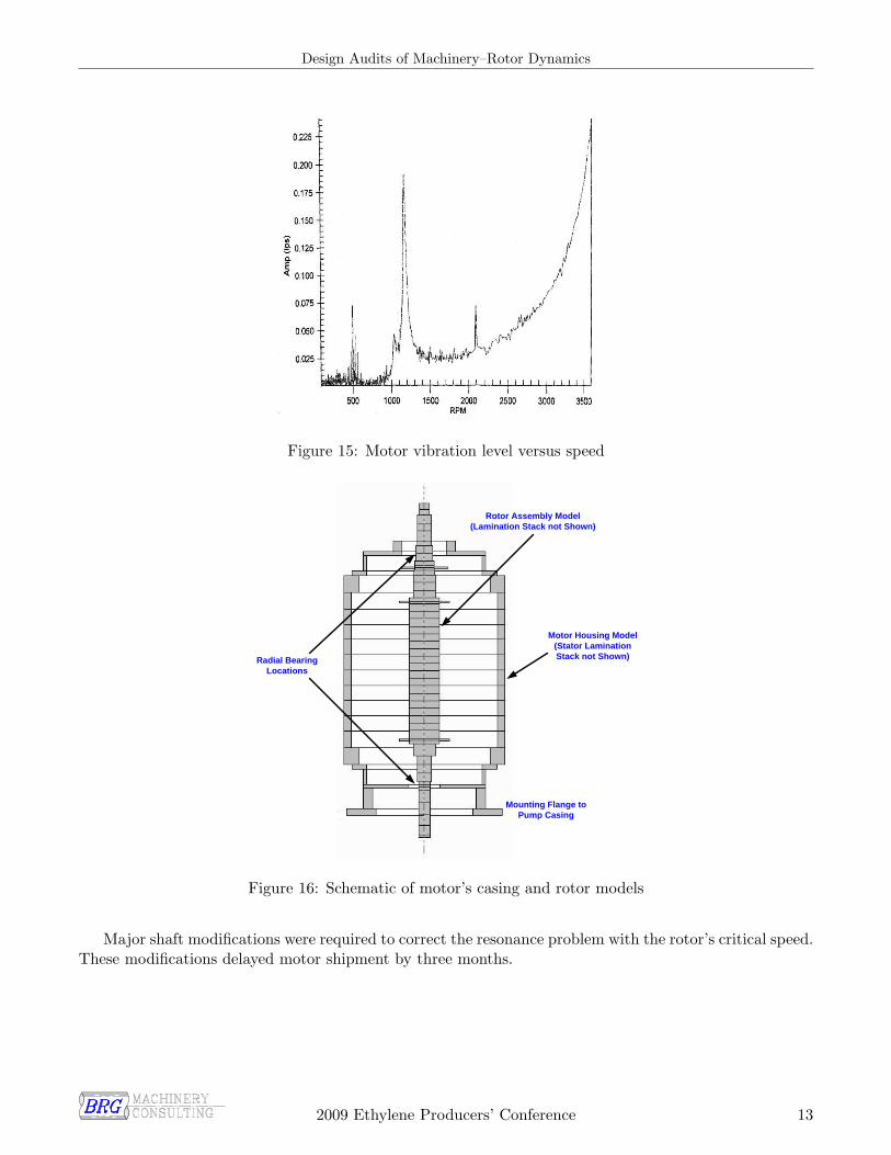
Figure 15 presents the motor’s vibrations measured during coastdown. At running speed, vibrationlevels are shown to exceed 0.2 in/sec (5 mm/sec) 0-peak, well above the specified limit. The manufacturerattributed the peak at approximately 1,200 rpm to be the motor’s first critical speed, but could not explainthe large increase in vibration as speed was increased.
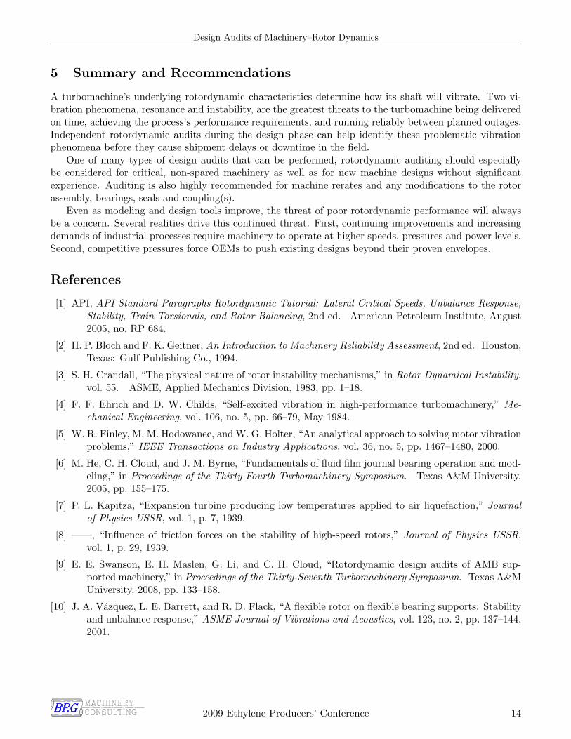
The manufacturer had conducted no rotordynamic analysis on this motor design. Therefore, modelsof the motor’s stator casing and rotor were developed and coupled into a single dynamic system. Figure16 presents a schematic of this model. Unbalance response analysis identified the vibration problem to becaused by a critical speed separation margin problem. The motor’s running speed and a critical speed at3,700 rpm were in a state of resonance.
The analysis also identified the 1,200 rpm peak to be associated with a natural frequency where theentire motor housing is pivoting about its bottom mounting flange. Commonly referred to as a “reedcritical frequency” [5], this natural frequency is not associated with the rotor’s critical speed as thoughtby the motor manufacturer.
2009 Ethylene Producers’ Conference 12
Design Audits of Machinery–Rotor Dynamics
Figure 15: Motor vibration level versus speed
Mounting Flange toPump Casing
Motor Housing Model(Stator Lamination Stack not Shown)
Rotor Assembly Model (Lamination Stack not Shown)
Radial BearingLocations
Figure 16: Schematic of motor’s casing and rotor models
Major shaft modifications were required to correct the resonance problem with the rotor’s critical speed.These modifications delayed motor shipment by three months.
2009 Ethylene Producers’ Conference 13
Design Audits of Machinery–Rotor Dynamics
5 Summary and Recommendations
A turbomachine’s underlying rotordynamic characteristics determine how its shaft will vibrate. Two vi-bration phenomena, resonance and instability, are the greatest threats to the turbomachine being deliveredon time, achieving the process’s performance requirements, and running reliably between planned outages.Independent rotordynamic audits during the design phase can help identify these problematic vibrationphenomena before they cause shipment delays or downtime in the field.
One of many types of design audits that can be performed, rotordynamic auditing should especiallybe considered for critical, non-spared machinery as well as for new machine designs without significantexperience. Auditing is also highly recommended for machine rerates and any modifications to the rotorassembly, bearings, seals and coupling(s).
Even as modeling and design tools improve, the threat of poor rotordynamic performance will alwaysbe a concern. Several realities drive this continued threat. First, continuing improvements and increasingdemands of industrial processes require machinery to operate at higher speeds, pressures and power levels.Second, competitive pressures force OEMs to push existing designs beyond their proven envelopes.
References
[1] API, API Standard Paragraphs Rotordynamic Tutorial: Lateral Critical Speeds, Unbalance Response,Stability, Train Torsionals, and Rotor Balancing, 2nd ed. American Petroleum Institute, August2005, no. RP 684.
[2] H. P. Bloch and F. K. Geitner, An Introduction to Machinery Reliability Assessment, 2nd ed. Houston,Texas: Gulf Publishing Co., 1994.
[3] S. H. Crandall, “The physical nature of rotor instability mechanisms,” in Rotor Dynamical Instability,vol. 55. ASME, Applied Mechanics Division, 1983, pp. 1–18.
[4] F. F. Ehrich and D. W. Childs, “Self-excited vibration in high-performance turbomachinery,” Me-chanical Engineering, vol. 106, no. 5, pp. 66–79, May 1984.
[5] W. R. Finley, M. M. Hodowanec, and W. G. Holter, “An analytical approach to solving motor vibrationproblems,” IEEE Transactions on Industry Applications, vol. 36, no. 5, pp. 1467–1480, 2000.
[6] M. He, C. H. Cloud, and J. M. Byrne, “Fundamentals of fluid film journal bearing operation and mod-eling,” in Proceedings of the Thirty-Fourth Turbomachinery Symposium. Texas A&M University,2005, pp. 155–175.
[7] P. L. Kapitza, “Expansion turbine producing low temperatures applied to air liquefaction,” Journalof Physics USSR, vol. 1, p. 7, 1939.
[8] ——, “Influence of friction forces on the stability of high-speed rotors,” Journal of Physics USSR,vol. 1, p. 29, 1939.
[9] E. E. Swanson, E. H. Maslen, G. Li, and C. H. Cloud, “Rotordynamic design audits of AMB sup-ported machinery,” in Proceedings of the Thirty-Seventh Turbomachinery Symposium. Texas A&MUniversity, 2008, pp. 133–158.
[10] J. A. Vazquez, L. E. Barrett, and R. D. Flack, “A flexible rotor on flexible bearing supports: Stabilityand unbalance response,” ASME Journal of Vibrations and Acoustics, vol. 123, no. 2, pp. 137–144,2001.
2009 Ethylene Producers’ Conference 14