LECTURE 18: Horn Antennas Rectangular horn antennas Circular
Upload
truongliemCategory
view
220download
4
Chandana & Prudhvi/ Star Vol.5 Issue 12(2), December (2017) ISSN: 2321-676X
7
DESIGN AND SIMULATION OF H-PLANE SECTORAL HORN ANTENNA WITH
ENHANCED BANDWIDTH
CHANDANA VISWANADHAM1 & Prof. PRUDHVI MALLIKARJUNA RAO
2
1Ph.D., student Andhra University, Visakhapatnam, Andhra Pradesh, India.
2Professor, Department of ECE, Andhra University, Visakhapatnam, Andhra Pradesh, India.
ABSTRACT
Various standard methods for feeding the pyramidal, cylindrical and tapered horns are popular and used in
many applications. Numerous technical papers are published in the open literature explaining the advantages and disadvantages of these methods. However, it is evident that most of these methods are suitable for narrow band
applications like conventional radars and satellite communications with some limitations. Very few papers have been published which suitable for U.W.B applications. In this paper, an optimized technique to enhance the bandwidth of
H-plane sectoral horn antenna is presented, which is used as an array element for linear array of H-plane sectoral
horns. The enhancement of bandwidth is achieved through optimization of impedance of the feed pin with he suitable mechanical modification. The frequency enhancement, lower down to 6 GHz is achieved without changing the
dimensions of the sectoral horn. It is observed that the simulated and measured results are in agreement.
KEYWORDS: Band Width Ratio (BWR), Electronic Warfare, Impedance, Matching networks, Traveling Wave Tubes (T.W.T), Ultra
Wide Band (U.W.B).
INTRODUCTION
Electronic Counter Measures (E.C.M) systems
are configured with high power transmitters consisting of
Digital Radio Frequency Memory (D.R.F.M), high
power microwave amplifiers and highly directive and
electronically steerable antenna [1-2]. The antenna
should withstand high power signals and shall have good
matching with free space impedance (Z0) of 120π Ω. The
active V.S.W.R of the array is very critical parameter in
these applications and depends on V.S.W.R of each
element in the array. Many engineers have experimented
standard and modified techniques to improve V.S.W.R of
pyramidal horns, such as dielectric loading, stub
matching, etc., [3 – 5]. These authors also explained the
disadvantages of these methods like reduction in gain
and operating bandwidths, though V.S.W.R is improved
to great extent in the operating band. Recently, ridge gap
waveguides are considered as guiding structures in high-
frequency applications. One of the major drawbacks of
these guiding structures is the operating bandwidth and
mostly these structures are suitable for narrow bandwidth
applications. This is not suitable for wide and U.W.B
array applications. Further, to maintain the spacing in the
array of sectoral horn antennas operating in 18-40 GHz,
6-18 GHz and 2-6 GHz frequency range, it is desirable to
feed point of the H-plane sectoral horn antenna element
should be from the back wall of the waveguide adapter.
The wideband coaxial to ridge gap waveguide transition
is based on five different sections of matching networks.
The introduced transition shows excellent return loss,
which is better than 15 dB over the entire frequency
range. In this method the pin of the co-axial connector is
directly inserted in the ridge of the waveguide plate of
the horn body. The radiating elements have smoothly
curved bent in the ridged transmission line in the plates
of the horns, which is suitable for feeding from co-axial
pin. The H-plane sectoral horn, as an aperture control
device, is designed with selected flare angle and aperture
shape is in accordance with the laws of optics for
limiting the beam width in the plane orthogonal to the
plane of scanning of the array.
SPECIFICATIONS
The specifications of the 8-18 GHz sectoral
horn are considered as the targeted specifications of side
fed H-plane sectoral horn antenna with frequency range
of 6-18 GHz in this paper. These are tabulated in Table-1.
These specifications are derived from the open literature.
The objective is to enhance the frequency range of this
antenna down to 6 GHz without any dimensional
changes.
Original Article
STAR Research Journal
Availableonlineatwww.starresearchjournal.com(StarInternationalJournal)
ENGINEERING UGC Journal No: 63023
Chandana & Prudhvi/ Star Vol.5 Issue 12(2), December (2017) ISSN: 2321-676X
8
TABLE 1
DESIGN SPECIFICATIONS
In the above Table, bandwidth enhancement is
considered by improving the V.S.W.R. without any
change in the dimensions. This is achieved by using
suitable probe for matching the impedance in 6-18 GHz
frequency range.
SPECIFICATIONS
Based on the above requirements, the
dimensional values have been computed using the design
equations [2] and the calculated values are tabulated at
Table-2. In the calculations, the dimension of the antenna
size is 130.55 x 8.2 x 225.35 mm, which is same as the
existing antenna. Now the objective is to design the H-
plane sectoral horn antenna with the same dimensions
with bandwidth enhancement up to 6 GHz. This is
achieved by designing a new feeding probe.
TABLE 2
DESIGN CALCULATIONS
Sl.
No.
Parameter Calculated specifications
1. Frequency
range
6–18 GHz or 8-18 GHz
2. DH (dBi) ~5.5 dBi @6 GHz
13.1dBi @18 GHz
3. DH 3.93 @ 7 GHz
20.46 @ 18 GHz
4. GH 80
5. b 8.2
6. X 8.69mm@ 7 GHz
15.06mm@18GHz
7. A 130.55 mm
8. R0 215.7 mm (Existing
dimensions)
9. lH 225.35 mm (Existing
dimensions)
Where, Hl Slant length of the horn, 0R Straight
length of the horn, A Aperture, H Flare angle,
HR Flare length and a Waveguide height, GH is
calculated constant.
DH is obtained from below equation.
50
HH
H
GbD
l
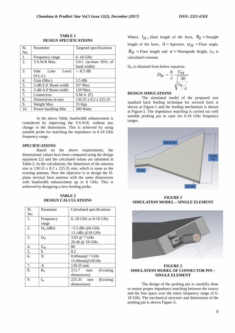
DESIGN SIMULATIONS
The simulated model of the proposed non
standard back feeding technique for sectoral horn is
shown at Figure-1 and the feeding mechanism is shown
at Figure-2. The impedance matching is carried out with
suitable probing pin to cater for 6-18 GHz frequency
ranges.
FIGURE I
SIMULATION MODEL – SINGLE ELEMENT
FIGURE 2
SIMULATION MODEL OF CONNECTOR PIN –
SINGLE ELEMENT
The design of the probing pin is carefully done
to ensure proper impedance matching between the source
and the free space over the entire frequency range of 6-
18 GHz. The mechanical structure and dimensions of the
probing pin is shown Figure-3.
Sl.
No.
Parameter Targeted specifications
1. Frequency range 6–18 GHz
2. V.S.W.R Max. 3.0:1 (at-least 85% of
band width)
3. Side Lobe Level
(S.L.L)
< -8.5 dB
4. Gain (Min.) 5.5 dBi
5. 3-dB E.P. Beam width 35° Max.
6. 3-dB A.P Beam width 120°Max.
7. Connectors S.M.A (F)
8. Dimensions in mm 130.55 x 8.2 x 225.35
9. Weight Max 15 Kgs
10. Power handling Min 300 Watts
Chandana & Prudhvi/ Star Vol.5 Issue 12(2), December (2017) ISSN: 2321-676X
9
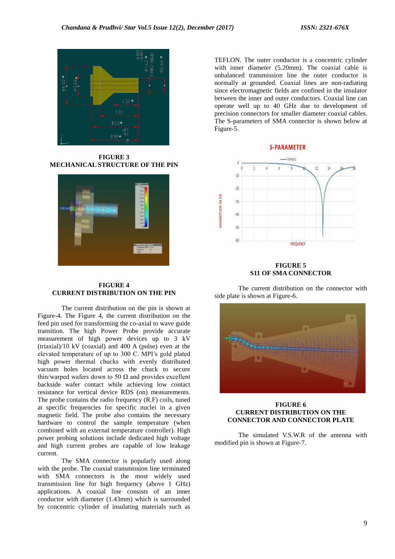
FIGURE 3
MECHANICAL STRUCTURE OF THE PIN
FIGURE 4
CURRENT DISTRIBUTION ON THE PIN
The current distribution on the pin is shown at
Figure-4. The Figure 4, the current distribution on the
feed pin used for transforming the co-axial to wave guide
transition. The high Power Probe provide accurate
measurement of high power devices up to 3 kV
(triaxial)/10 kV (coaxial) and 400 A (pulse) even at the
elevated temperature of up to 300 C. MPI’s gold plated
high power thermal chucks with evenly distributed
vacuum holes located across the chuck to secure
thin/warped wafers down to 50 Ω and provides excellent
backside wafer contact while achieving low contact
resistance for vertical device RDS (on) measurements.
The probe contains the radio frequency (R.F) coils, tuned
at specific frequencies for specific nuclei in a given
magnetic field. The probe also contains the necessary
hardware to control the sample temperature (when
combined with an external temperature controller). High
power probing solutions include dedicated high voltage
and high current probes are capable of low leakage
current.
The SMA connector is popularly used along
with the probe. The coaxial transmission line terminated
with SMA connectors is the most widely used
transmission line for high frequency (above 1 GHz)
applications. A coaxial line consists of an inner
conductor with diameter (1.43mm) which is surrounded
by concentric cylinder of insulating materials such as
TEFLON. The outer conductor is a concentric cylinder
with inner diameter (5.20mm). The coaxial cable is
unbalanced transmission line the outer conductor is
normally at grounded. Coaxial lines are non-radiating
since electromagnetic fields are confined in the insulator
between the inner and outer conductors. Coaxial line can
operate well up to 40 GHz due to development of
precision connectors for smaller diameter coaxial cables.
The S-parameters of SMA connector is shown below at
Figure-5.
FIGURE 5
S11 OF SMA CONNECTOR
The current distribution on the connector with
side plate is shown at Figure-6.
FIGURE 6
CURRENT DISTRIBUTION ON THE
CONNECTOR AND CONNECTOR PLATE
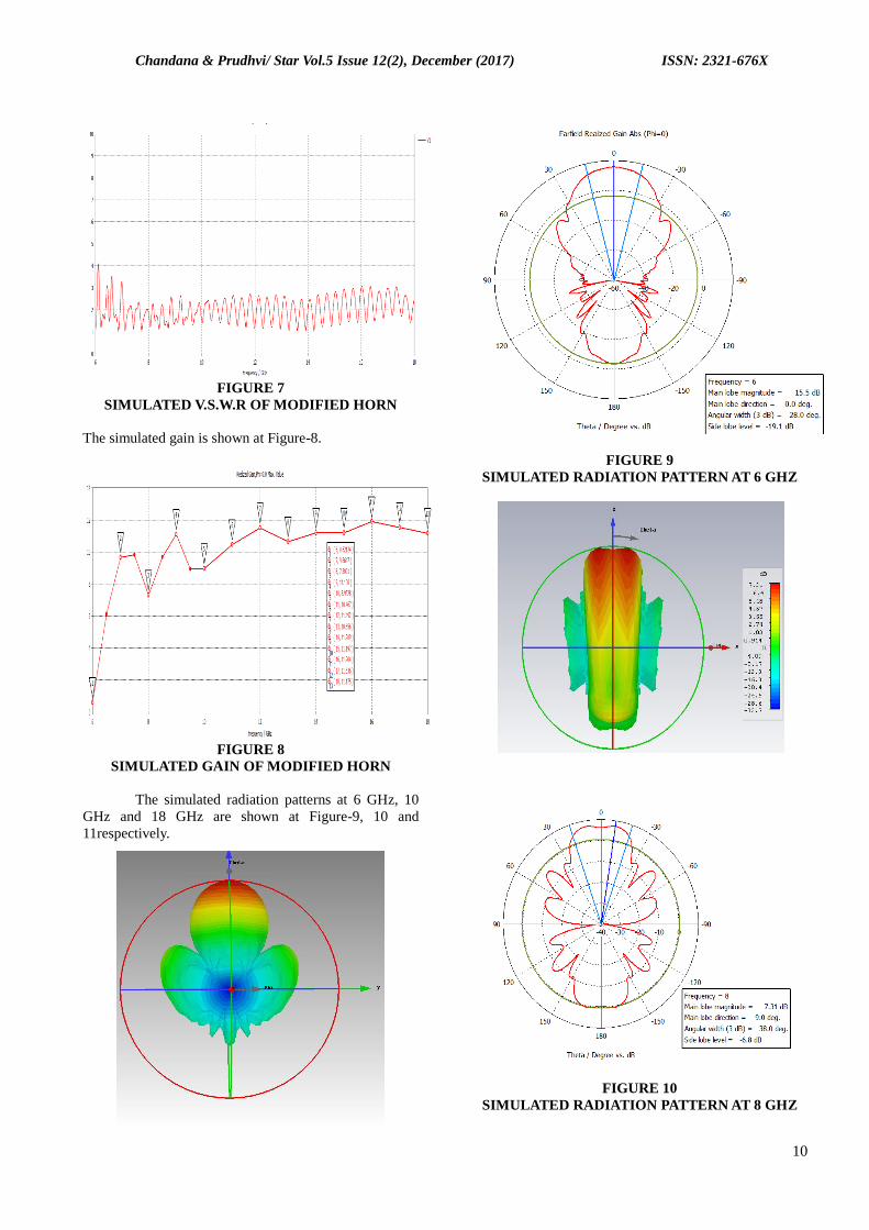
The simulated V.S.W.R of the antenna with
modified pin is shown at Figure-7.
Chandana & Prudhvi/ Star Vol.5 Issue 12(2), December (2017) ISSN: 2321-676X
10
FIGURE 7
SIMULATED V.S.W.R OF MODIFIED HORN
The simulated gain is shown at Figure-8.
FIGURE 8
SIMULATED GAIN OF MODIFIED HORN
The simulated radiation patterns at 6 GHz, 10
GHz and 18 GHz are shown at Figure-9, 10 and
11respectively.
FIGURE 9
SIMULATED RADIATION PATTERN AT 6 GHZ
FIGURE 10
SIMULATED RADIATION PATTERN AT 8 GHZ

Chandana & Prudhvi/ Star Vol.5 Issue 12(2), December (2017) ISSN: 2321-676X
11
FIGURE 11
SIMULATED RADIATION PATTERN AT 18 GHZ
The simulated model of eight element linear
array of sectoral horn is shown at Figure-12.
FIGURE 12
SIMULATION MODEL OF EIGHT ELEMENT
ARRAY
The simulated radiation patterns of the array are
shown at Figure-13 to 15. The simulated data with equal
phase to all eight ports are fed and hence the mai beam is
expected at center of the array.
FIGURE 13
SIMULATED RADIATION PATTERN AT 6 GHZ
Chandana & Prudhvi/ Star Vol.5 Issue 12(2), December (2017) ISSN: 2321-676X
12
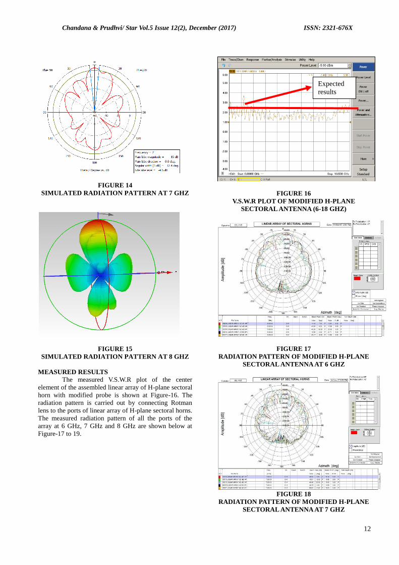
FIGURE 14
SIMULATED RADIATION PATTERN AT 7 GHZ
FIGURE 15
SIMULATED RADIATION PATTERN AT 8 GHZ
MEASURED RESULTS
The measured V.S.W.R plot of the center
element of the assembled linear array of H-plane sectoral
horn with modified probe is shown at Figure-16. The
radiation pattern is carried out by connecting Rotman
lens to the ports of linear array of H-plane sectoral horns.
The measured radiation pattern of all the ports of the
array at 6 GHz, 7 GHz and 8 GHz are shown below at
Figure-17 to 19.
FIGURE 16
V.S.W.R PLOT OF MODIFIED H-PLANE
SECTORAL ANTENNA (6-18 GHZ)
FIGURE 17
RADIATION PATTERN OF MODIFIED H-PLANE
SECTORAL ANTENNA AT 6 GHZ
FIGURE 18
RADIATION PATTERN OF MODIFIED H-PLANE
SECTORAL ANTENNA AT 7 GHZ
Expected
results

Chandana & Prudhvi/ Star Vol.5 Issue 12(2), December (2017) ISSN: 2321-676X
13
FIGURE 19
RADIATION PATTERN OF MODIFIED H-PLANE
SECTORAL ANTENNA AT 8 GHZ
CONCLUSION
A sectoral horn antenna with suitable
modification to feed point for extension of frequency up
to 6 GHz is simulated and presented in this paper. The
V.S.W.R of the antenna is close to the design
specification of 3:1 in the extended frequency range also.
The radiation patterns and gain parameters are also
simulated and presented. The simulation of array has
been carried out for all parameters. The array elements
and connectors are fabricated and is assembled with
modified pins. The measured radiation patterns of the
array are presented in the extended frequency range.
ACKNOWLEDGEMENT
The authors are thankful to the engineers
working at BEL for sparing their valuable time during
the simulation. We also extend our sincere thanks to
management of B.E.L for providing all the facilities like
Simulation tools, High end work stations, during the
simulation work. We sincerely extend our gratitude to
Prof. G Sashibhushana Rao, HOD, ECE department,
Andhra University, Visakhapatnam for his support
during the preparation of the paper.
REFERENCES
1. Hans Schantz, “Antenna as Transducers and
Antennas as transformer“, in the title of Art and
Science of Ultra Wide Band antennas” 1st edition,
2005, Artech publications
2. Pues H.F, “An impedance-matching techniques for
increasing the bandwidth of micro strip antennas”,
Antennas and Propagation, IEEE transactions Vol.
37, issue 11, pages 1345-1354, ISSN: 0018-926X,
06 Aug 2002.
3. Constantine A Balanis, “Antenna Theory Analysis
and design with multimedia CD”, 3rd
edition, Wiley
India, reprint 2012.
4. Ronaldo O. dos Santos and Carlos Leonidas da S.
S. Sobrinho, “FDTD method: Analysis of an one-
dimensional array of H-plane sectoral horn
antennas with dielectric lens”, Revista Científica
Periódica, Telecomunicações, Telecomunicações,
Vol. 06, No.1, pp. 28-32, June 2003
5. Tae-Young Kim, Young-Min Yoon, Gun-Su Kim,
and Boo-Gyoun Kim, “A Linear Phased Array
Antenna Composed of Inductive Loaded Patch
Antennas”, IEEE Antennas and Wireless
Propagation Letters (Volume: 10), 2011
6. Pues H.F, “An impedance-matching techniques for
increasing the bandwidth of micro strip antennas”,
Antennas and Propagation, IEEE transactions Vol.
37, issue 11, pages 1345-1354, ISSN: 0018-926X,
06 Aug 2002.
7. P. M. Russo, R. C. Ruddock, and L. Peters, Jr., “A
Method for Computing E-Plane Patterns of Horn
Antennas,” IEEE Trans. Antennas Propagat., Vol.
AP-13, No. 2, pp. 219–224, March 1965.
8. J. S. Yu, R. C. Ruddock, and L. Peters, Jr.,
“Comprehensive Analysis for E-Plane of Horn
Antennas by Edge Diffraction Theory,” IEEE
Trans. Antennas Propagat., Vol. AP-14, No.2, pp.
138–149, March 1966.
9. Ch Viswanadham, Prof P Mallikarjuna Rao,
“Hybrid tapering and aperture smoothening for
improving V.S.W.R of U.W.B Phased Array Horn
Antenna for ECM applications”, Feb 2016,
presented at ICACCS, Coimbatore, India,
10. M. J. May bell and P. S. Simon, “Pyramidal Horn
Gain Calculation with Improved Accuracy,” IEEE
Trans. Antennas Propagat., Vol. 41, No. 7, pp. 884–
889, July 1993.
11. W. D. Burnside and C. W. Chuang, “An Aperture-
Matched Horn Design,” IEEE Trans. Antennas
Propagat., Vol. AP-30, No. 4, pp. 790–796, July
1982.