Design and Performance of a Two-Dimensional Tactile...
8
Design and Performance of a Two-Dimensional Tactile Slip Display Todd E. Murphy, Robert J. Webster III, and Allison M. Okamura The Johns Hopkins University, Dept. of Mechanical Engineering, 3400 N. Charles St, Baltimore, MD 21218 USA {tmurphy, robert.webster, aokamura}@jhu.edu http://www.haptics.me.jhu.edu Abstract. We introduce a novel two-degree-of-freedom haptic display capable of reproducing the sensation of sliding contact on a fingertip. The modular device can be attached to a PHANTOM haptic interface and generates tactile sensations by actuating a ball positioned under the user’s index finger. Specifications for the device and mechanical design considerations are presented. Integration of the slip display, PHANTOM, and a virtual environment results in a system capable of generating both tactile and kinesthetic haptic sensations. We also present the results of two psychophysical experiments, detection of slip angle and slip velocity variation, on human perception of sliding contact. These experiments demonstrate that, despite design and manufacturing tolerance limitations, the functional performance of the device is sufficient for realistic display of sliding contact. 1 Introduction The sense of touch plays a crucial role in our perception of the world around us and in our performance of identification and grasping tasks. To improve the immersiveness of virtual environments and the effectiveness of other robot-human interactions, systems must include accurate haptic representations of the relevant objects. For full transparency and functionality in such environments, it is important to simulate a wide variety of possible human-object interaction modes. For example, humans often tap, rub, or envelop objects during exploration. While kinesthetic force information is widely used in haptic simulations, tactile sensations are often lacking, in part because design and construction of accurate and transparent tactile displays is very challenging. Virtual reality and teleoperated systems can be improved through the development of new interfaces and algorithms capable of displaying tactile sensations. We present here the design of a device for displaying sliding contact at a fingertip in two degrees of freedom (DOF). The device displays relative motion between the fingertip and a virtual surface through the use of an actuated ball under the fingertip, and can be used as a modular attachment to a 3-DOF PHANTOM haptic interface. Initial experiments with a slip-enabled virtual environment have garnered positive feedback from users. 130
Transcript of Design and Performance of a Two-Dimensional Tactile...

Design and Performance of a Two-Dimensional Tactile Slip Display
Todd E. Murphy, Robert J. Webster III, and Allison M. Okamura
The Johns Hopkins University, Dept. of Mechanical Engineering, 3400 N. Charles St, Baltimore, MD 21218 USA
{tmurphy, robert.webster, aokamura}@jhu.edu http://www.haptics.me.jhu.edu
Abstract. We introduce a novel two-degree-of-freedom haptic display capable of reproducing the sensation of sliding contact on a fingertip. The modular device can be attached to a PHANTOM haptic interface and generates tactile sensations by actuating a ball positioned under the user’s index finger. Specifications for the device and mechanical design considerations are presented. Integration of the slip display, PHANTOM, and a virtual environment results in a system capable of generating both tactile and kinesthetic haptic sensations. We also present the results of two psychophysical experiments, detection of slip angle and slip velocity variation, on human perception of sliding contact. These experiments demonstrate that, despite design and manufacturing tolerance limitations, the functional performance of the device is sufficient for realistic display of sliding contact.
1 Introduction
The sense of touch plays a crucial role in our perception of the world around us and in our performance of identification and grasping tasks. To improve the immersiveness of virtual environments and the effectiveness of other robot-human interactions, systems must include accurate haptic representations of the relevant objects. For full transparency and functionality in such environments, it is important to simulate a wide variety of possible human-object interaction modes. For example, humans often tap, rub, or envelop objects during exploration. While kinesthetic force information is widely used in haptic simulations, tactile sensations are often lacking, in part because design and construction of accurate and transparent tactile displays is very challenging.
Virtual reality and teleoperated systems can be improved through the development of new interfaces and algorithms capable of displaying tactile sensations. We present here the design of a device for displaying sliding contact at a fingertip in two degrees of freedom (DOF). The device displays relative motion between the fingertip and a virtual surface through the use of an actuated ball under the fingertip, and can be used as a modular attachment to a 3-DOF PHANTOM haptic interface. Initial experiments with a slip-enabled virtual environment have garnered positive feedback from users.
130
Allison M Okamura
Proceedings of EuroHaptics 2004, Munich Germany, June 5-7, 2004.

2 Murphy, Webster and Okamura
Psychophysical experiments demonstrate that the performance of our device, despite limitations in slip angle and velocity control, is sufficient for realistic haptic display.
1.1 Previous Work
Given the importance of tactile sensing for manipulation and exploration, it is no surprise that there has been active research in this area. Much of the work has focused on displaying vibrations, temperature, texture, or geometry. The last two are often displayed on haptic devices employing an array of actuated point contacts. However, most of these systems have no direct application to the display of sliding contact forces. Recognizing the role that slip detection plays in human grasping, there has also been a great deal of work on slip sensing, such as for teleoperated robotic graspers [1]. A system equipped with these types of sensors and our slip display would create an unprecedented degree of telepresence.
There has also been previous work on development of devices for displaying sliding contact. Johnson and Phillips used a 1-DOF system for administering neuroscience experiments [2]. Chen and Marcus developed a 1-DOF device that we drew from heavily in our work [3]. Salada, et al. [4,5,6] demonstrated that 1-DOF sliding can be displayed on their bench-top haptic device with enough fidelity to make it perceptually comparable to sliding a finger across a real surface. Also, the force-feedback trackball developed by Engel, et al. [7] gives valuable insight into the design of a two DOF device.
Other recent work provides examples of tactile displays attached to a larger kinesthetic haptic device. The effect of a rolling ball on the fingertip was studied in [8]. In contrast to the system we present, the ball does not slide with respect to the finger, but displays a moving point contact.
We also see a link between our work and studies on tactile illusions, e.g. [9]; understanding and exploiting these effects could lead to improved strategies for controlling our device.
2 Device Design
The device, pictured in Figures 1 and 3, consists of a spherical ball supported under the user’s fingertip. The user contacts a portion of the ball through an aperture in the mechanism housing. Two orthogonal wheels actuate the ball and create relative motion between the surface of the ball and the user’s fingertip. The device connects to the PHANTOM through a passive gimbal attachment. In the following sections we describe the design specifications and the current device design.
2.2 Specifications
To smooth integration with the PHANTOM haptic device and maximize transparency, we sought to minimize the size and weight of the device. However, there is a fundamental tradeoff between miniaturization and perception of a flat
131

Design and Performance of a Two-Dimensional Tactile Slip Display 3
sliding contact surface. As ball diameter is reduced, the contact area with the fingertip becomes smaller and at its limit approaches a point contact. A larger ball increases the size and weight of the device. We selected a 25.4 mm diameter Delrin ball as the contact object and designed around this centerpiece.
To determine the required driving torque, we estimated that the normal force applied by a user on the ball would be 1.5N. This was measured by pushing on a scale with a force comparable to that used when sliding across a real-world surface. To determine motor torque, the coefficient of friction between the fingertip and a sanded Delrin ball was also required. Several sources (e.g. [10]) suggest a value of µ = 0.5 as a reasonable estimate. Combining these specifications with the known ball size and estimated gear ratios led to a motor torque requirement of 7.5 mNm.
Another important specification necessary for motor selection was the desired maximum speed at which the ball would turn. We desired the ability to accurately recreate the slip sensation for hand speeds up to 50 cm/s. Using the 25.4 mm ball diameter, this requires a rotational speed of approximately 6.3 rpm for the ball.
From [5], we knew the size of the aperture where the fingertip contacts the ball would affect users’ perception of the device. Using this reference and our own testing, we targeted for an aperture of 15 mm in diameter.
2.3 Design
Users experience a slip contact with the ball, which is spun by two orthogonal wheels via friction contact. The ball is supported by low-friction rolling contact in a
Fig. 1. The two-degree of freedom slip display mounted on the output link of a PHANTOM haptic interface
A
B
2 1
ball
bearing
2
1
bearing
ball
path
Fig. 2. The positions of the drive wheels (1 and 2) result in additional frictional contact and off-axis ball rotation (axis A is desired and axis B results)
132

4 Murphy, Webster and Okamura
special bearing developed for this project, a hemispherical pocket lined with ball bearings. Around the top edge of the pocket is a bearing race. The bearing is designed to allow the ball bearings to roll under the ball until they reach the race, where they may move around the rim and then return to the area beneath the ball.
As suggested by the design in [7], the optimal placement of each drive wheel would be on the axis of rotation created by the other wheel. This arrangement minimizes the friction generated by each wheel during rotation of the other wheel. However, when both wheels turn simultaneously this arrangement still requires that some slip occur at the wheel-ball interface. Our bearing design prevented placement of the drive wheels in this ideal configuration, so we first tried to solve the friction problem through the use of “omniwheels,” which are designed for applications where wheels must impart forces tangential to the outer rim, yet present little impedance to motion normal to the disk of the wheel. However, we found it difficult to manufacture omniwheels with a sufficiently circular outer perimeter at this scale, resulting in undesirable performance on a number of fronts. Consequently, the final design incorporates drive wheels that are solid cylinders with O-rings stretched around the perimeter for a high-friction contact with the ball. As mentioned earlier, each wheel is not located on the axis of rotation created by the other wheel. Thus, with only one wheel turning, the other wheel creates an additional constraint, altering the axis of rotation and changing the path a point on the ball would trace under the user’s fingertip, as illustrated in Figure 2. It is not clear whether moving both wheels simultaneously can eliminate this effect, so this is a topic of future research. This problem motivated the slip angle experiment discussed in Section 4.
The design includes two motors as part of the fingertip assembly, where they supply torque to the drive wheels through a gear train. The motors selected are capable of 6.75 mNm of torque and a maximum speed of 9,900 rpm. Reductions in the gearhead and the mechanism limit the ball speed to 5.4 rev/sec, corresponding to a maximum slip speed of about 43 cm/s. To account for tolerances in the assembly and to provide a consistent normal force between the wheels and the ball, each module containing the drive wheel, gear train, and motor is hinged and loaded against the ball with torsional springs. The entire fingertip assembly is connected to the PHANTOM through a passive gimbal attachment that permits rotation around three axes while maintaining the point of finger contact at a fixed location relative to the PHANTOM’s output link. The entire assembly weighs 192 grams.
3 System Integration
To date, the slip display has been integrated with the PHANTOM haptic device and demonstrated with a planar virtual environment created using Microsoft Visual C++. The slip display is attached to the PHANTOM with a gimbal assembly, as shown in Figure 1. The PHANTOM and the slip display were controlled using a single computer equipped with a PHANTOM control card in addition to a quadrature encoder board and a D/A card used for controlling the motors on the slip display.
The program contained a graphic thread running at 10 Hz and a haptic thread running at 333 Hz. During interaction, the position of the user’s fingertip is obtained
133

Design and Performance of a Two-Dimensional Tactile Slip Display 5
using the encoders on the PHANTOM. The position is differentiated and filtered to obtain an estimate of the fingertip velocity. The environment contained two types of virtual objects. When the cursor was moved over the first type of object, the ball was driven at the user’s estimated linear velocity, but in the opposite direction, to simulate the sensation of sliding a finger across a tabletop. The second type of object behaved like a conveyor belt; users were displayed slip at a constant speed while positioned over the object. Subjective evaluation of this system by a number of users indicates that these virtual surfaces provide realistic slip sensations.
4 Psychophysical Experiments
Two experiments were performed to evaluate the impact of device limitations. As mentioned earlier, the location of the drive wheels induces some error in the ball’s axis of rotation. Thus, the first experiment evaluates the level at which angular differences in the direction of slip become noticeable to users of the device. Other potential sources of error in ball motion come from friction or inconsistencies on the rotating portions of the device. For example, there are finite tolerances for holes drilled in round parts (such as drive wheels and gears), and in the straightness of rotating shafts. Such manufacturing tolerances could induce periodic variation in the velocity of the ball, even with perfect control of the motor speed. Thus, the second experiment explores the level at which these variations are detectable by a typical user. Both experiments were conducted using the device shown in Figure 4. This device mimics the tactile interface of the slip display by using the same lightly sanded Delrin ball and a similar aperture. In this arrangement, the ball is directly attached to the shaft of a single encoded motor, so it spins around a known axis at a known angular velocity.
Fig. 3. An exploded view of the device assembly
Fig. 4. Single-axis slip device used in psychophysical experiments
134

6 Murphy, Webster and Okamura
4.1 Angle Discrimination Experiment
To determine the effect of the angular direction of slip on user perception, we performed an experiment to determine the absolute threshold of the direction of relative slip on the index finger. We placed the test apparatus on a table oriented such that the direction of ball motion simulated the feeling of placing one’s finger on a horizontal surface and drawing the finger towards oneself.
Twelve subjects (seven male, five female, aged 21 to 31 years) participated in the experiments. Each participant was instructed to use the index finger of the right hand to press on the surface of the ball with a light, constant pressure of approximately 0.5 N. Each user was asked to press on a scale at the start of the experiment until the reading showed 50 g in order to get a feel for this level of force. All test participants were familiarized with the device and the intent of the experiment before starting. The device was aligned so that the axis of rotation was parallel with the participant’s coronal plane, identified as the “straight” orientation, and each subject had a chance to experience this. The device was then rotated 50 degrees counterclockwise and each subject experienced this as an example of an “angled” configuration.
Subjects were then blindfolded and presented with a random sequence of 10 angles ranging from 0-50 degrees, in 5 degree increments. During the experiment the ball was spun at approximately 1.25 rev/s, creating a linear slip rate under the fingertip of 10 cm/s. Between presentation of each individual angle, subjects were asked to lift their index finger off the device. Subjects were allowed to feel each angle for as long as they liked, but were instructed not to conduct search activities such as moving their index finger in the horizontal plane or varying contact pressure. For each angle, the subjects verbally selected either “angled” or “straight” as the best description of the sensation they were experiencing. Subject responses are presented in Figure 5. These results demonstrate that the average user cannot discriminate angles up to about 20 degrees of deviation from the nominal value. The results are encouraging for our application, as they suggest that users’ perceptual experience will not be affected by the limitations of our device.
0.0
0.2
0.4
0.6
0.8
1.0
0 5 10 15 20 25 30 35 40 45 50
Slip Angle (deg)
Pro
po
rtio
n o
f "A
ng
led
" R
esp
on
ses
Fig. 5. Subject responses from the angle discrimination experiment. The average angle of detection was between 20 and 25 degrees.
135

Design and Performance of a Two-Dimensional Tactile Slip Display 7
4.2 Velocity Variation Experiment
A second experiment was conducted to determine the level at which humans can perceive sinusoidal variations in the velocity of a sliding contact under their index finger. The experiment was administered with the same device used in the first experiment, and the ball was spun at the same nominal velocity (simulating a 10 cm/s slip speed). Superimposed on this speed was a sine wave with variable amplitude and a constant frequency selected to match the frequency of ball rotation, approximately 1.25 Hz. The amplitude of the sine wave was varied as a ratio of the mean speed. When the ratio was zero, the slip speed was a constant 10 cm/s. When the ratio was 1.0, the speed of slip varied from 0 – 20 cm/s.
Subjects interacted with the test device in the same way as in the angle experiment, but were not blindfolded because no visual cues were available to them in this experiment. However, participants did wear headphones to eliminate auditory cues provided by sounds from the motor and gear head as the speed varied. Similar to the first experiment, subjects were allowed to feel both the zero amplitude and maximum amplitude test cases and were told they would be presented with a randomly ordered sequence of values in between. Subjects were then presented with eleven values of amplitude in increments of 10% of the nominal velocity, and asked to classify each as “varying” or “constant.” Subject responses are presented in Figure 6, showing that significant amplitude ratios (up to 0.3) can generally be displayed without an average user detecting any velocity variation.
5 Conclusions and Future Work
In this paper we present a two-dimensional tactile device that displays sliding contact to the user. The slip display was demonstrated successfully in conjunction
0.0
0.2
0.4
0.6
0.8
1.0
0.0 0.1 0.2 0.3 0.4 0.5 0.6 0.7 0.8 0.9 1.0Amplitude Ratio
Pro
po
rtio
n o
f "V
aryi
ng
" R
esp
on
ses
Fig. 6. Subject responses from the slip velocity variation experiment. The average amplitude ratio detected was between 0.3 and 0.4.
136
8 Murphy, Webster and Okamura
with a PHANTOM haptic interface and appropriate virtual environment to provide combined tactile and kinesthetic sensations. Anecdotally, users suggested the tactile sensation they felt was effective in simulating slip. Future work on the device may include investigating methods for encoding the motion of the ball itself, since the current method does not account for slippage of the ball relative to the wheels.
Because of difficulties in designing an optimal slip display, we performed two psychophysical experiments to better understand the effects of implementation issues. The slip angle experiment showed that the average angle detection threshold is larger than the angle errors resulting from our device design. The velocity variation experiment showed that, given reasonable device tolerances, most users are unlikely to detect any small variations in speed that may occur. Future work may include more detailed studies in this area, including a probit analysis to better estimate the underlying model for these stimuli.
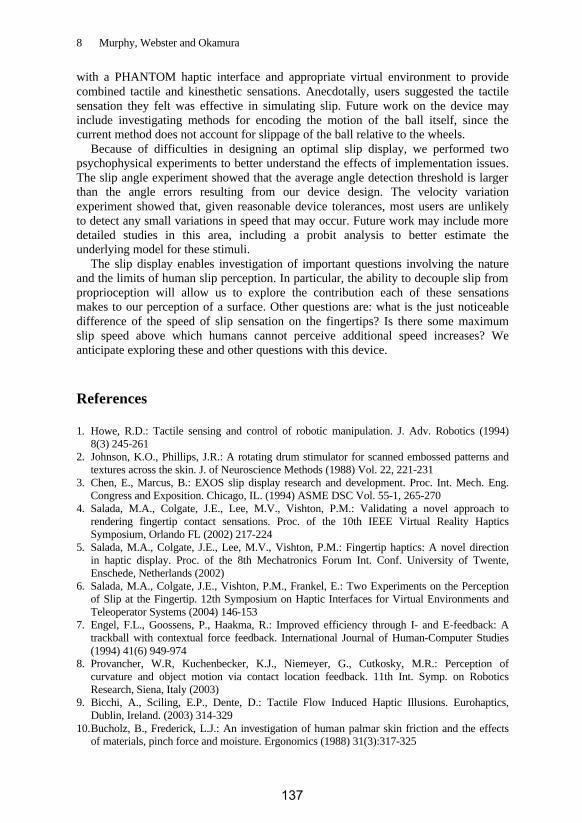
The slip display enables investigation of important questions involving the nature and the limits of human slip perception. In particular, the ability to decouple slip from proprioception will allow us to explore the contribution each of these sensations makes to our perception of a surface. Other questions are: what is the just noticeable difference of the speed of slip sensation on the fingertips? Is there some maximum slip speed above which humans cannot perceive additional speed increases? We anticipate exploring these and other questions with this device.
References
1. Howe, R.D.: Tactile sensing and control of robotic manipulation. J. Adv. Robotics (1994) 8(3) 245-261
2. Johnson, K.O., Phillips, J.R.: A rotating drum stimulator for scanned embossed patterns and textures across the skin. J. of Neuroscience Methods (1988) Vol. 22, 221-231
3. Chen, E., Marcus, B.: EXOS slip display research and development. Proc. Int. Mech. Eng. Congress and Exposition. Chicago, IL. (1994) ASME DSC Vol. 55-1, 265-270
4. Salada, M.A., Colgate, J.E., Lee, M.V., Vishton, P.M.: Validating a novel approach to rendering fingertip contact sensations. Proc. of the 10th IEEE Virtual Reality Haptics Symposium, Orlando FL (2002) 217-224
5. Salada, M.A., Colgate, J.E., Lee, M.V., Vishton, P.M.: Fingertip haptics: A novel direction in haptic display. Proc. of the 8th Mechatronics Forum Int. Conf. University of Twente, Enschede, Netherlands (2002)
6. Salada, M.A., Colgate, J.E., Vishton, P.M., Frankel, E.: Two Experiments on the Perception of Slip at the Fingertip. 12th Symposium on Haptic Interfaces for Virtual Environments and Teleoperator Systems (2004) 146-153
7. Engel, F.L., Goossens, P., Haakma, R.: Improved efficiency through I- and E-feedback: A trackball with contextual force feedback. International Journal of Human-Computer Studies (1994) 41(6) 949-974
8. Provancher, W.R, Kuchenbecker, K.J., Niemeyer, G., Cutkosky, M.R.: Perception of curvature and object motion via contact location feedback. 11th Int. Symp. on Robotics Research, Siena, Italy (2003)
9. Bicchi, A., Sciling, E.P., Dente, D.: Tactile Flow Induced Haptic Illusions. Eurohaptics, Dublin, Ireland. (2003) 314-329
10. Bucholz, B., Frederick, L.J.: An investigation of human palmar skin friction and the effects of materials, pinch force and moisture. Ergonomics (1988) 31(3):317-325
137