Design and Optimized of Solar PV System a Case Study of ...
9
Journal of Electrical and Electronic Engineering 2020; 8(1): 27-35 http://www.sciencepublishinggroup.com/j/jeee doi: 10.11648/j.jeee.20200801.15 ISSN: 2329-1613 (Print); ISSN: 2329-1605 (Online) Design and Optimized of Solar PV System a Case Study of KIOT Administration Offices Degarege Anteneh 1, * , Birhanu Alene 1, 2 1 Department of Electrical & Computer Engineering, Debre Berhan University, Debre Berhan, Ethiopia 2 Department of Electrical & Computer Engineering, Bahir Dar University, Bahir Dar, Ethiopia Email address: * Corresponding author To cite this article: Degarege Anteneh, Birhanu Alene. Design and Optimized of Solar PV System a Case Study of KIOT Administration Offices. Journal of Electrical and Electronic Engineering. Vol. 8, No. 1, 2020, pp. 27-35. doi: 10.11648/j.jeee.20200801.15 Received: August 2, 2019; Accepted: November 12, 2019; Published: March 2, 2020 Abstract: Design and optimized of solar PV system is a leading trend in modern energy management of distribution system. In modern or currently most of the life, customers take in energy from different sources like, sunlight, wind, diesel, biomass, even batteries and from main grid of electric power and facilitate not only its conversion into electric energy, but also the demand management, storage and generation association with the system’s output. In recently distributions generations (micro grid) implementations combine loads with sources, allow for intentional islanding and try to use the available waste heat. These solutions rely on complex communication and control, and are dependent on key components and require extensive site engineering. This paper focuses on the design, optimization and simulation of 48-V rated stand-alone solar PV using HOMER software that is suppling primarily by photovoltaic (PV) panels and using battery and diesel for comparison, but which also has the capability to tie in to a main electrical grid. A system of this size should be able to supply power for KIOT administration office buildings. The most important objectives of this paper are the selections of an appropriate PV array, the selection or design of a charge controller and the design of the system’s renewable energy converter. Keywords: Design of PV, HOMER, Charge Controller, Battery Sizing, Feasibility Study, Inverter 1. Introduction One of the best ways to get power to remote, off-grid locations and reliable electric power in grid connected system, whether in developed or developing countries is through Solar Home System (SHS). The system includes Solar PV, battery, solar charge controller and inverter. In most cases consumers consume solar energy at evening hours. So, solar energy shall be stored into batteries [1]. A solar charge controller is similar to the voltage regulator. It regulates the voltage and current that is coming from the solar panels and going to the battery. Most of the batteries are fully charged at 14 to 14.5 volts. On the other hand, battery's life time drastically reduces due to the discharge over the level of 70%-80%, at this discharge level the battery voltage normally goes down to 11.5 volts. Each battery has a certain limit of capacity. Battery lifetime reduces drastically due to overcharging and deep discharging. As battery is a very expensive component of a Solar Home System, it is necessary to protect the batteries from being over charged or deeply discharged. In this case charge controller plays a vital role to protect the battery. A series charge controller disables further current flow into batteries when they are full. A shunt charge controller diverts excess electricity to an auxiliary or "shunt" load, such as an electric water heater, when batteries are full. Since the industrial revolution, human activities have constantly changed the natural composition of earth’s atmosphere. Concentrations of trace atmospheric gases, nowadays termed “greenhouse gases” are increasing at an alarming rate [2]. The consumption of fossil fuels, conversion of forests to agricultural land and the emission of industrial chemicals are principal contribution factor to air pollution. Under normal atmospheric conditions, energy from the sun controls Earth’s whether and climate pattern. Heating of Earth’s surface from the sun radiates energy back to the space. This will result the greenhouse effect or global warming. Global and national scenarios of primary and in
Transcript of Design and Optimized of Solar PV System a Case Study of ...
Journal of Electrical and Electronic Engineering 2020; 8(1): 27-35 http://www.sciencepublishinggroup.com/j/jeee doi: 10.11648/j.jeee.20200801.15 ISSN: 2329-1613 (Print); ISSN: 2329-1605 (Online)
Design and Optimized of Solar PV System a Case Study of KIOT Administration Offices
Degarege Anteneh1, *
, Birhanu Alene1, 2
1Department of Electrical & Computer Engineering, Debre Berhan University, Debre Berhan, Ethiopia 2Department of Electrical & Computer Engineering, Bahir Dar University, Bahir Dar, Ethiopia
Email address:
*Corresponding author
To cite this article: Degarege Anteneh, Birhanu Alene. Design and Optimized of Solar PV System a Case Study of KIOT Administration Offices. Journal of
Electrical and Electronic Engineering. Vol. 8, No. 1, 2020, pp. 27-35. doi: 10.11648/j.jeee.20200801.15
Received: August 2, 2019; Accepted: November 12, 2019; Published: March 2, 2020
Abstract: Design and optimized of solar PV system is a leading trend in modern energy management of distribution system.
In modern or currently most of the life, customers take in energy from different sources like, sunlight, wind, diesel, biomass,
even batteries and from main grid of electric power and facilitate not only its conversion into electric energy, but also the
demand management, storage and generation association with the system’s output. In recently distributions generations (micro
grid) implementations combine loads with sources, allow for intentional islanding and try to use the available waste heat.
These solutions rely on complex communication and control, and are dependent on key components and require extensive site
engineering. This paper focuses on the design, optimization and simulation of 48-V rated stand-alone solar PV using HOMER
software that is suppling primarily by photovoltaic (PV) panels and using battery and diesel for comparison, but which also has
the capability to tie in to a main electrical grid. A system of this size should be able to supply power for KIOT administration
office buildings. The most important objectives of this paper are the selections of an appropriate PV array, the selection or
design of a charge controller and the design of the system’s renewable energy converter.
Keywords: Design of PV, HOMER, Charge Controller, Battery Sizing, Feasibility Study, Inverter
1. Introduction
One of the best ways to get power to remote, off-grid
locations and reliable electric power in grid connected
system, whether in developed or developing countries is
through Solar Home System (SHS). The system includes
Solar PV, battery, solar charge controller and inverter. In
most cases consumers consume solar energy at evening
hours. So, solar energy shall be stored into batteries [1]. A
solar charge controller is similar to the voltage regulator. It
regulates the voltage and current that is coming from the
solar panels and going to the battery. Most of the batteries are
fully charged at 14 to 14.5 volts. On the other hand, battery's
life time drastically reduces due to the discharge over the
level of 70%-80%, at this discharge level the battery voltage
normally goes down to 11.5 volts. Each battery has a certain
limit of capacity. Battery lifetime reduces drastically due to
overcharging and deep discharging. As battery is a very
expensive component of a Solar Home System, it is
necessary to protect the batteries from being over charged or
deeply discharged. In this case charge controller plays a vital
role to protect the battery. A series charge controller disables
further current flow into batteries when they are full. A shunt
charge controller diverts excess electricity to an auxiliary or
"shunt" load, such as an electric water heater, when batteries
are full. Since the industrial revolution, human activities have
constantly changed the natural composition of earth’s
atmosphere. Concentrations of trace atmospheric gases,
nowadays termed “greenhouse gases” are increasing at an
alarming rate [2]. The consumption of fossil fuels,
conversion of forests to agricultural land and the emission of
industrial chemicals are principal contribution factor to air
pollution. Under normal atmospheric conditions, energy from
the sun controls Earth’s whether and climate pattern. Heating
of Earth’s surface from the sun radiates energy back to the
space. This will result the greenhouse effect or global
warming. Global and national scenarios of primary and in

28 Degarege Anteneh and Birhanu Alene: Design and Optimized of Solar PV System a Case Study of KIOT Administration Offices
particular electrical energy consumption for the coming
decades basically all predict a strong increase in technical
utilization of renewable energy (RE). A significant increase
in the use of RE satisfies the requirements of climate
protection and allows suitable growth in energy consumption
for newly developed and developing countries. At the same
time, the aims to decrease the share of fossil primary energies
in the medium and long time, and has the potential to reduce
the share of nuclear energy to zero. However, to achieve this
goal all RE technologies (hydro power, wind power, biomass,
geothermal heat and solar irradiation) have to be mobilized in
a balanced way and in coordinated time sequence, which is
according to their economic market relevance and their
technical potential. Among RE, solar irradiation will in the
long term have to become the main contributor to a global
renewable energy supply because of its unlimited potential.
Photovoltaic (PV) is favored by its flexibility with respect to
size and fields of application, its long life-time and low
required maintenance. PV system is a device that mainly
used to convert solar energy (which is the utilization of the
radiant energy from the sun) to the electricity [3]. Solar
power is often used interchangeably with solar energy but
refer more specifically to the conversion of sunlight into
electricity. Presented of PV technology that used to convert
solar energy to the electric energy was acknowledge and used
in many countries around the world nowadays.
Photovoltaic (PV) is the technology used to convert the
energy directly from the sunlight into electricity by using the
solar cell. The photon from the sunlight knock electron into
higher energy which will produce electricity. A typical
photovoltaic cell produces less than 3 watts at approximately
0.5 volt dc, cells must be connected in series-parallel
configurations to produce enough power for high power
applications. The electricity produce are in direct current
which can be used to power equipment or to recharge battery.
The first application of photovoltaic was used to power up
the orbiting satellites and space shuttle. Nowadays,
photovoltaic is important in grid-connection generation
which required an inverter to convert DC current to AC
current [4].
Table 1. Factor that can attract people interested using PV system.
Advantage of using PV Disadvantage of using PV
Have a warranty until 20 years and more. and System is very durable and not
easily damage The production of electricity is uneven throughout the day.
Solar energy production is quite System does not produce electricity at the night or when it is overcast.
Pay off point (which mean no need pay monthly bill) Even there are many
advantages of PV system. Initial cost of installation PV system is very high.
This research is involved to design the software to make
the calculation to choose the solar panel and inverter become
easier. The software must be based on the case study to
implement the solar panel to the KIOT administration offices.
To choose the suitable solar panel and inverter that can be
implemented to KIOT administration offices, the data of the
power consumption must be get first before can design the
suitable software to make the calculation to find and choose
the suitable inverter and solar panel that can be implemented
to KIOT administration offices.
2. Solar Radiation
Based on different researches, 51% of the total solar
energy reaches at ground, 6% is reflected by the atmosphere,
10% is reflected by the clouds, 4% is reflected from the
earth’s surface, 16% is absorbed by the atmosphere and the
other 3% is absorbed by the clouds as shown in the figure
below [5-6].
Figure 1. Total sun radiation and earth energy budget.
Journal of Electrical and Electronic Engineering 2020; 8(1): 27-35 29
Solar radiation is an electromagnetic wave emitted by the
sun’s surface that originates in the bulk of the sun where
fusion reactions convert hydrogen atoms into helium. Every
second 3.89×1026J of nuclear energy is released by the sun’s
core. This nuclear energy flux is rapidly converted into
thermal energy and transported toward the surface of the star
where it is released in the form of electromagnetic radiation.
The power density emitted by the sun is of the order of
64MW/m2 of which approximately 1370W/m2 reach the top
of the Earth’s atmosphere with no significant absorption in
the space [8]. The latter quantity is called the solar constant.
The spectral range of the solar radiation is very large and
encompasses nano metric wavelengths of gamma- and x-
rays through metric wavelengths of radio waves.
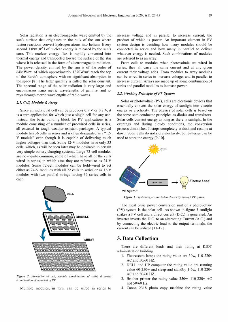
2.1. Cell, Module & Array
Since an individual cell can be produces 0.5 V or 0.8 V, it
is a rare application for which just a single cell for any use.
Instead, the basic building block for PV applications is a
module consisting of a number of pre-wired cells in series,
all encased in tough weather-resistant packages. A typical
module has 36 cells in series and is often designated as a “12-
V module” even though it is capable of delivering much
higher voltages than that. Some 12-V modules have only 33
cells, which, as will be seen later may be desirable in certain
very simple battery charging systems. Large 72-cell modules
are now quite common, some of which have all of the cells
wired in series, in which case they are referred to as 24-V
modules. Some 72-cell modules can be field-wired to act
either as 24-V modules with all 72 cells in series or as 12-V
modules with two parallel strings having 36 series cells in
each.
Figure 2. Formation of cell, module (combination of cells) & array
(combination of modules) of PV.
Multiple modules, in turn, can be wired in series to
increase voltage and in parallel to increase current, the
product of which is power. An important element in PV
system design is deciding how many modules should be
connected in series and how many in parallel to deliver
whatever energy is needed. Such combinations of modules
are referred to as an array.
From cells to modules when photovoltaic are wired in
series, they all carry the same current and at any given
current their voltage adds. From modules to array modules
can be wired in series to increase voltage, and in parallel to
increase current. Arrays are made up of some combination of
series and parallel modules to increase power.
2.2. Working Principle of PV System
Solar or photovoltaic (PV), cells are electronic devices that
essentially convert the solar energy of sunlight into electric
energy or electricity. The physics of solar cells is based on
the same semiconductor principles as diodes and transistors.
Solar cells convert energy as long as there is sunlight. In the
evenings and during cloudy conditions, the conversion
process diminishes. It stops completely at dusk and resume at
dawn. Solar cells do not store electricity, but batteries can be
used to store the energy [9-10].
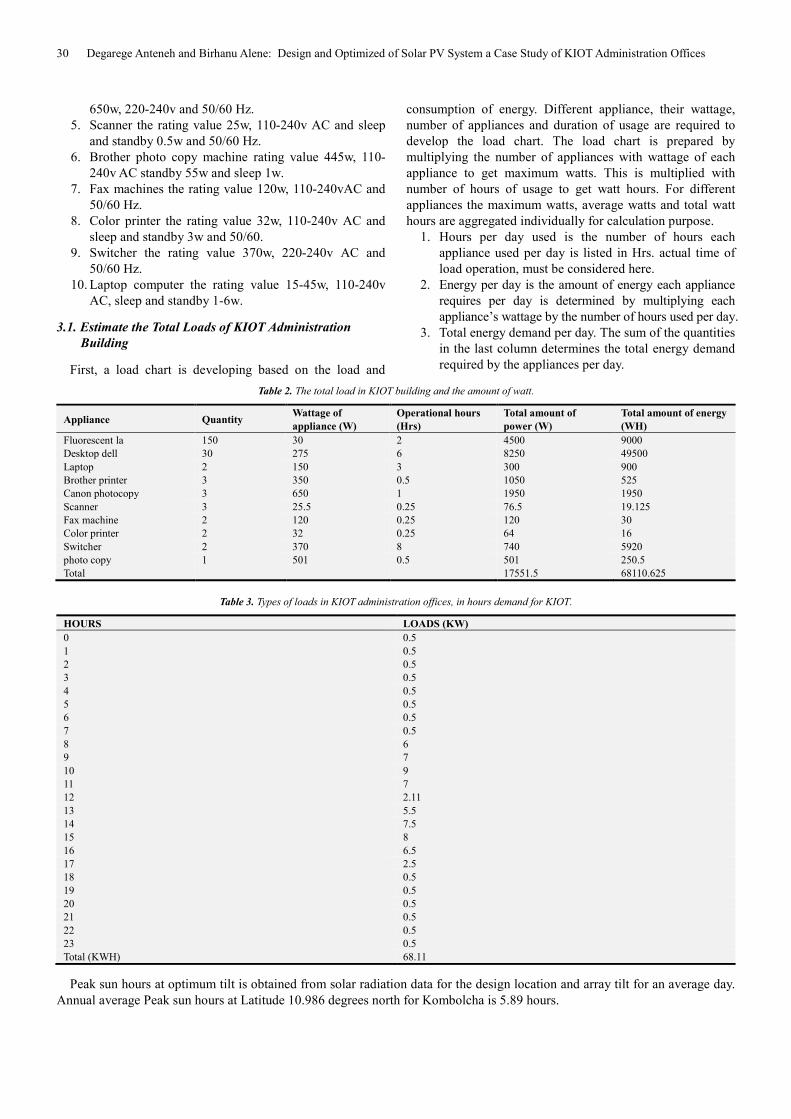
Figure 3. Light energy converted to electricity through PV system.
The most basic power conversion unit of a photovoltaic
(PV) system is the solar cell. As shown in figure 3 sunlight
strikes a PV cell and a direct current (D.C.) is generated. An
inverter inverts the D.C. to an alternating Current (A.C.) and
by connecting the electric load to the output terminals, the
current can be utilized [11-12].
3. Data Collection
There are different loads and their rating at KIOT
administration building.
1. Fluorescent lamps the rating value are 30w, 110-220v
AC and 50/60 HZ.
2. DELL and HP computer the rating value are running
value 60-250w and sleep and standby 1-6w, 110-220v
AC and 50/60 HZ.
3. Brother printer the rating value 350w, 110-220v AC
and 50/60 Hz.
4. Canon 2318 photo copy machine the rating value
30 Degarege Anteneh and Birhanu Alene: Design and Optimized of Solar PV System a Case Study of KIOT Administration Offices
650w, 220-240v and 50/60 Hz.
5. Scanner the rating value 25w, 110-240v AC and sleep
and standby 0.5w and 50/60 Hz.
6. Brother photo copy machine rating value 445w, 110-
240v AC standby 55w and sleep 1w.
7. Fax machines the rating value 120w, 110-240vAC and
50/60 Hz.
8. Color printer the rating value 32w, 110-240v AC and
sleep and standby 3w and 50/60.
9. Switcher the rating value 370w, 220-240v AC and
50/60 Hz.
10. Laptop computer the rating value 15-45w, 110-240v
AC, sleep and standby 1-6w.
3.1. Estimate the Total Loads of KIOT Administration
Building
First, a load chart is developing based on the load and
consumption of energy. Different appliance, their wattage,
number of appliances and duration of usage are required to
develop the load chart. The load chart is prepared by
multiplying the number of appliances with wattage of each
appliance to get maximum watts. This is multiplied with
number of hours of usage to get watt hours. For different
appliances the maximum watts, average watts and total watt
hours are aggregated individually for calculation purpose.
1. Hours per day used is the number of hours each
appliance used per day is listed in Hrs. actual time of
load operation, must be considered here.
2. Energy per day is the amount of energy each appliance
requires per day is determined by multiplying each
appliance’s wattage by the number of hours used per day.
3. Total energy demand per day. The sum of the quantities
in the last column determines the total energy demand
required by the appliances per day.
Table 2. The total load in KIOT building and the amount of watt.
Appliance Quantity Wattage of
appliance (W)
Operational hours
(Hrs)
Total amount of
power (W)
Total amount of energy
(WH)
Fluorescent la 150 30 2 4500 9000
Desktop dell 30 275 6 8250 49500
Laptop 2 150 3 300 900
Brother printer 3 350 0.5 1050 525
Canon photocopy 3 650 1 1950 1950
Scanner 3 25.5 0.25 76.5 19.125
Fax machine 2 120 0.25 120 30
Color printer 2 32 0.25 64 16
Switcher 2 370 8 740 5920
photo copy 1 501 0.5 501 250.5
Total 17551.5 68110.625
Table 3. Types of loads in KIOT administration offices, in hours demand for KIOT.
HOURS LOADS (KW)
0 0.5
1 0.5
2 0.5
3 0.5
4 0.5
5 0.5
6 0.5
7 0.5
8 6
9 7
10 9
11 7
12 2.11
13 5.5
14 7.5
15 8
16 6.5
17 2.5
18 0.5
19 0.5
20 0.5
21 0.5
22 0.5
23 0.5
Total (KWH) 68.11
Peak sun hours at optimum tilt is obtained from solar radiation data for the design location and array tilt for an average day.
Annual average Peak sun hours at Latitude 10.986 degrees north for Kombolcha is 5.89 hours.

Journal of Electrical and Electronic Engineering 2020; 8(1): 27-35 31
Figure 4. Monthly solar radiation of Kombolcha.
3.2. Solar PV System Design Calculation for KIOT
Administration Building
In this part, determine the number of inverters, charge
controller, battery, solar PV modules and series and parallel
connection of battery and determine the rating value of each
equipment based on the collected data (electrical loads). The
figure shows below the block diagram of the connection
procedures of KIOT administration offices.
Figure 5. Block diagram of the connection procedures.
3.2.1. Mounting Structure
The PV module should be designed in such a way that it
can withstand rain, hail, wind and other adverse conditions.
Tilting angle optimally varies the efficiency of the solar PV
module so; the mounting structure also serves as a PV
module tilting structure which tilts the PV arrays at an angle
determined by the latitude of the site location, to maximize
the solar insulations falling on the panels. The optimum tilt
angle required to maximize the solar insulations changes as
the position of the sun varies every month. Similarly, shading
has a significant effect on PV generation. Partial shading can
reduce the system production up to 90%. Thus, it is essential
that the PV arrays to be installed at a suitable location
without any difficulties.
The angle formed between the plane of the equator and a
line drawn from the center of the sun to the center of the
earth is called the solar declination, δ. It varies between the
extremes of ± 23.45◦, and a simple sinusoidal relationship
that assumes a 365-day year and which puts the spring
equinox on day n = 81 provides a very good approximation.
� � 23.45 sin�360 � 365�� � 81�� (1)
Then, the design month is May.
n=121.
� � 23.45 sin�360 � 365�121 � 81��
� � 14.9
Then, the altitude angle of the sun
�� � 90° � � � �= 90-10.986+14.9= 64.114
The tilt angle that would make the sunray perpendicular to
the module at noon would therefore be Tilt angle= 90° �
�� � 90 � 64.114 � 25.886

32 Degarege Anteneh and Birhanu Alene: Design and Optimized of Solar PV System a Case Study of KIOT Administration Offices
3.2.2. Cost Estimation of KIOT Administration Building
PV panels are the most expensive part of a solar electric
system; as such, they are sometimes targets for theft.
Vandalism can also be a problem. For larger loads, their high
capital cost can render them a less preferable option if grid
extensions or fuel for generators are readily available.
Table 4. Cost considerations of PV system design of KIOT.
Components Cost Total cost ($) Percentage of total cost
PV module 0.6 ($/w) 11352 38.08
Battery $345 9660 32.4
Inverter $200/KW 4000 13.42
Charge controller 750.75 3753.75 12.6
Mounting 500 1.7
Labor 100 0.3
Miscellaneous 200 0.7
Cables 150 0.5
Maintenance 100 0.3
Total $29815.75 100%
Regular maintenance on batteries is essential; they should be checked every month, with the electrolyte level replenished as
needed. Properly maintained, batteries should last several years before needing replacement.
3.2.3. Electrical Loads
The average hourly electrical loads for each month of the year for the KIOT administration building are inputs of HOMER
software. The system immediately graphs the load and calculates parameters as shown in figure 6 below.
Figure 6. Daily power usage of KIOT and encode to HOMER software.
4. Simulation Analysis
The simulation process models the system configuration. It
serves two purposes. First, it determines whether the system is
feasible or not. HOMER considers the system to be feasible if
it can adequately serve the electric loads and satisfy any other
constraints imposed by the user. Second, it estimates the life-
cycle cost of the system, which is the total cost of installing
and operating the system over its lifetime. The quantity to
represent the life-cycle cost of the system is the total net
present cost (NPC). This single value includes all costs and
revenues that occur within the project lifetime, with future
cash flows discounted to the present. The total net present cost
includes the initial capital cost of the system components, the
cost of any component replacements that occur within the
project lifetime, the cost of maintenance and fuel.
Table 5 below is generated based on the set of input values
of the system configuration. The costs, capacity, quantity and
lifespan of each component of the system are taken from the
different websites. The diesel price is 0.75$/L and it is the
current price of diesel in the country. Figure 7 shows the
complete configuration of the system. It is composed of the
PV panel, generating unit, batteries, converters, electrical
loads and the AC and DC bus bars.

Journal of Electrical and Electronic Engineering 2020; 8(1): 27-35 33
Table 5. Inputs of data used for homer software simulation.
Considerations PV Diesel generator Battery Converter
Size (KW) 18.9 1 6594AH 1
Capital ($) 600/KW 200/KW 345 200
Replacement cost ($) 400/KW 150/KW 300 200
Op & ma cost ($/yr) 0 0.6 60
Sizes considered (KW) 0, 18.9 0, 5, 10, 15, 25, 40, 50 0, 10, 20, 25, 30
Quantities considered 0, 1, 2, 3, 4, 5, 6, 7
Life time 25 years 30660hrs 5453KWh 10yrs
4.1. Hybrid PV-Diesel System Optimizations Analysis
Figure 7. HOMER hybrid combination of PV and diesel with battery and
converter.
The optimization process determines the best possible
system configuration. In HOMER, the best possible, or
optimal, system configuration is the one that satisfies the
user-specified constraints at the lowest total net present cost.
Finding the optimal system configuration may involve
deciding on the standalone of components that the system
should contain, the size or quantity of each component, and
the dispatch strategy the system should use. In the
optimization process, HOMER simulates many different
system configurations, discards the infeasible ones, ranks the
feasible ones according to total net present cost, and presents
the feasible one with the lowest total net present cost as the
optimal system configuration.
The optimization results are generated in either of two
forms; an overall form in which the top-ranked system
configurations are listed according to their net present cost
(NPC) and in a categorized form where only the least-cost
system configuration is considered for each system.
Figure 8. Hybrid system supply optimizations analysis.
Figure 9. HOMER output of standalone PV system.
4.2. Standalone PV System
The result shows when we use PV system consider as
standalone, so the graphs tell about different cost relation of
over all the system. Currently, PV cell have high initial cost
due to the it increase the total cost of the system, but PV has
less O&M, COE and relatively low operating cost.
34 Degarege Anteneh and Birhanu Alene: Design and Optimized of Solar PV System a Case Study of KIOT Administration Offices
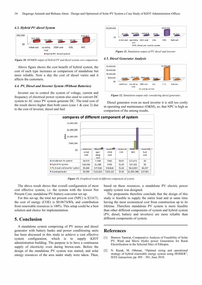
4.3. Hybrid PV-diesel System
Figure 10. HOMER output of Hybrid PV and diesel system cost comparison.
Above figure shows the cost benefit of hybrid system, the
cost of each type increases as comparison of standalone but
more reliable. Now a day the cost of diesel varies and it
affects the customers.
4.4. PV, Diesel and Inverter System (Without Batteries)
Inverter use to control the system of voltage, current and
frequency of electrical power system also used to convert DC
system to AC since PV system generate DC. The total cost of
the result shows higher than both cases (case 1 & case 2) due
to the cost of inverter, diesel and fuel.
Figure 11. Simulation output of PV, diesel and inverter.
4.5. Diesel Generator Analysis
Figure 12. Simulation output only considering diesel generator.
Diesel generator even no need inverter it is still too costly
in operating and maintenance (O&M), so, that NPC is high as
comparison of the among results.
Figure 13. Graphical result of different component of system.
The above result shows that overall configuration of most
cost effective system, i.e. the system with the lowest Net
Present Cost, standalone PV-battery-converter set-up.
For this set-up, the total net present cost (NPC) is $21673,
the cost of energy (COE) is $0.067/kWh, and contribution
from renewable resources is 100%. This setup could be a best
solution and choice for implementation.
5. Conclusion
A standalone system comprising of PV arrays and diesel
generator with battery banks and power conditioning units
has been discussed in this study to achieve a cost effective
system configuration, which is to supply KIOT
administration building. The purpose is to have a continuous
supply of electricity even during brown-outs. Before the
design of the standalone PV system was started, and solar
energy resources of the area under study were taken. Then,
based on these resources, a standalone PV electric power
supply system was designed.
The proponents therefore conclude that the design of this
study is feasible to supply the entire load and at same time
having the most economical cost from construction up to its
lifetime. Therefore standalone PV system is more feasible
than other different components of system and hybrid system
(PV, diesel, battery and inverters) are more reliable than
different components of system.
References
[1] Bimrew Tamirat, Comparative Analysis of Feasibility of Solar PV, Wind and Micro Hydro power Generation for Rural Electrification in the Selected Sites of Ethiopia.
[2] N. Razak, M. Othman, “Optimal sizing and operational strategy of hybrid renewable energy system using HOMER”, IEEE transaction, pp. 495 – 501, June 2010.
Journal of Electrical and Electronic Engineering 2020; 8(1): 27-35 35
[3] A. T. D. Perera, R. A. Attalage, K. K. C. K. Perera and V. P. C. Dassanayake, “Designing standalone hybrid energy systems minimizing initial investment, life cycle cost and pollutant emission”, Energy, 2013.
[4] S. M. Hakimi and S. M. Moghaddas-Tafreshi, “Optimal sizing of a stand-alone hybrid power system via particle swarm optimization for Kahnouj area in south-east of Iran”, Renewable Energy.
[5] G. Bekele and G. Tadesse, “Feasibility study of small Hydro/PV/Wind hybrid system for off-grid rural electrification in Ethiopia”, Applied Energy, 2011.
[6] Farret, F. A. and Simoes, M. G. (2006) Integration of Alternative Energy Sources of Energy. John Wiley & Sons, Hoboken.
[7] DOE’s Office of Energy Efficiency and Renewable Energy (2004) Solar Energy Technologies Program Multi-Year Technical Plan 2003-2007.
[8] Keyhani, A., Marwal, M. N. and Dai, M. (2010) Integration of Green and Renewable Energy in Electric Power Systems. John Wiley and Sons, Hoboken.
[9] http://rredc.nrel.gov/solar
[10] H. Bai, C. Mai, “The impact of bidirectional DC-DC converter on the inverter operation and battery current in hybrid electric vehicles”, Power Electronics and ECCE Asia (ICPE & ECCE), 2011 IEEE 8th International Conference on May 2011.
[11] Steeby, Donald L. Alternative Energy: Sources and Systems. The Green Destination Series. Clifton Park NY, USA: Delmar Cengage Learning. 1st Edition; 2012.
[12] Hart, Daniel W. Introduction to Power Electronics. Prentice Hall. 1st Edition; 1996.
[13] Morra, James. “Multi-Input Power Converter Will Upgrade Renewable Energy Networks.” Electronic Design. Online. Published 10 June 2015.
[14] PV Battery: Photovoltaic System Component. Solar Direct 2018.
[15] Rashid, Muhammad H. Power Electronics: Circuits, Devices, and Applications. Upper Saddle River NJ, USA: Pearson Educational Press. 4th Edition; 2014.
[16] F. A. Farret and M. G. Simões, Integration of alternative sources of energy, John Wiley & Sons, New Jersey (2006).