DESIGN AND OPTIMIZATION OF PARABOLIC TROUGH...
22
DESIGN AND OPTIMIZATION OF PARABOLIC TROUGH ORGANIC RANKINE CYCLE POWERPLANTS Andrew C. McMahan Sanford A. Klein Douglas T. Reindl University of Wisconsin - Madison Solar Energy Laboratory July 12, 2006
Transcript of DESIGN AND OPTIMIZATION OF PARABOLIC TROUGH...
DESIGN AND OPTIMIZATION OF PARABOLIC TROUGH ORGANIC
RANKINE CYCLE POWERPLANTSAndrew C. McMahan
Sanford A. KleinDouglas T. Reindl
University of Wisconsin - MadisonSolar Energy Laboratory
July 12, 2006
Summary
• Optimal design of power cycles for solar-thermal applications requires techniques different from those used in traditional powerplant design

Background• Organic Rankine Cycles
– Organic working fluids (toluene, n-pentane)– Well suited for lower resource temperatures– Used extensively in geothermal applications– Compact, economical design relative to steam Rankine cycles
Österreichische 400 kW ORC
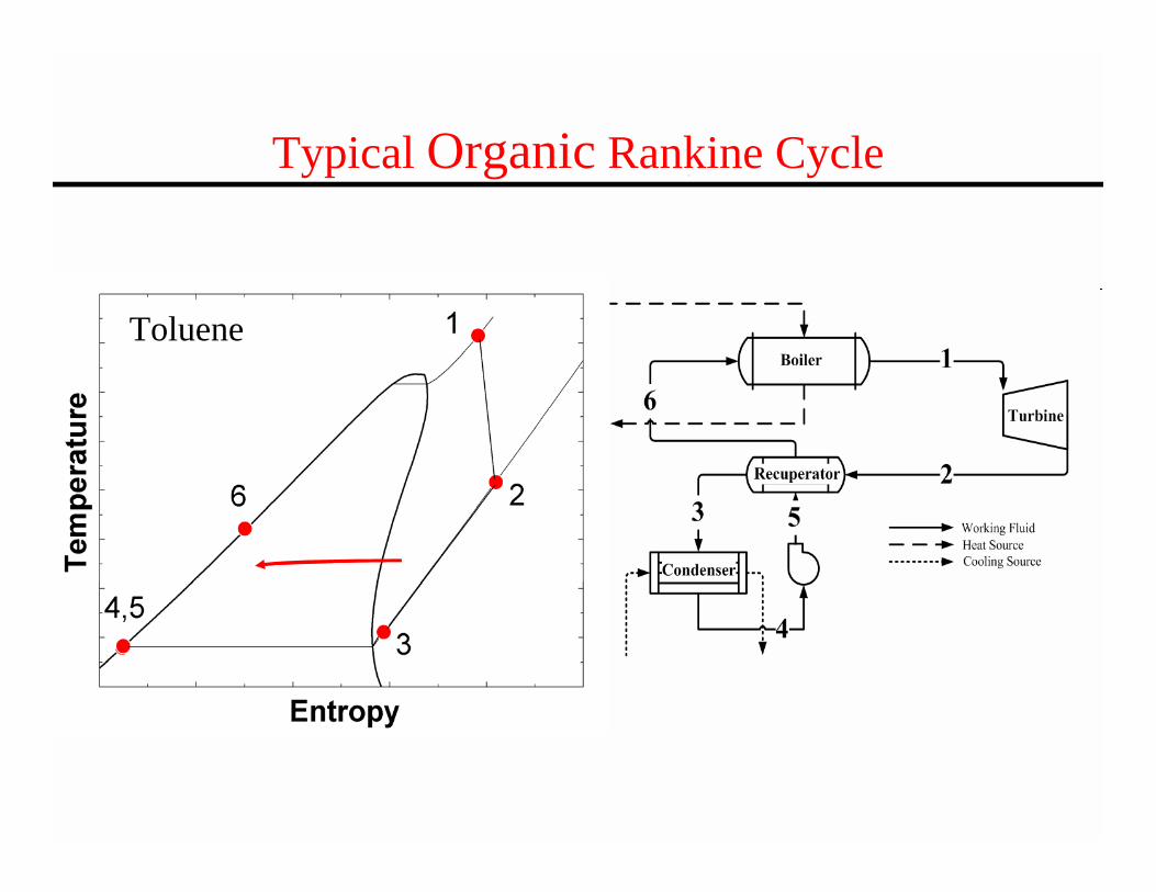
Typical Organic Rankine Cycle
Toluene
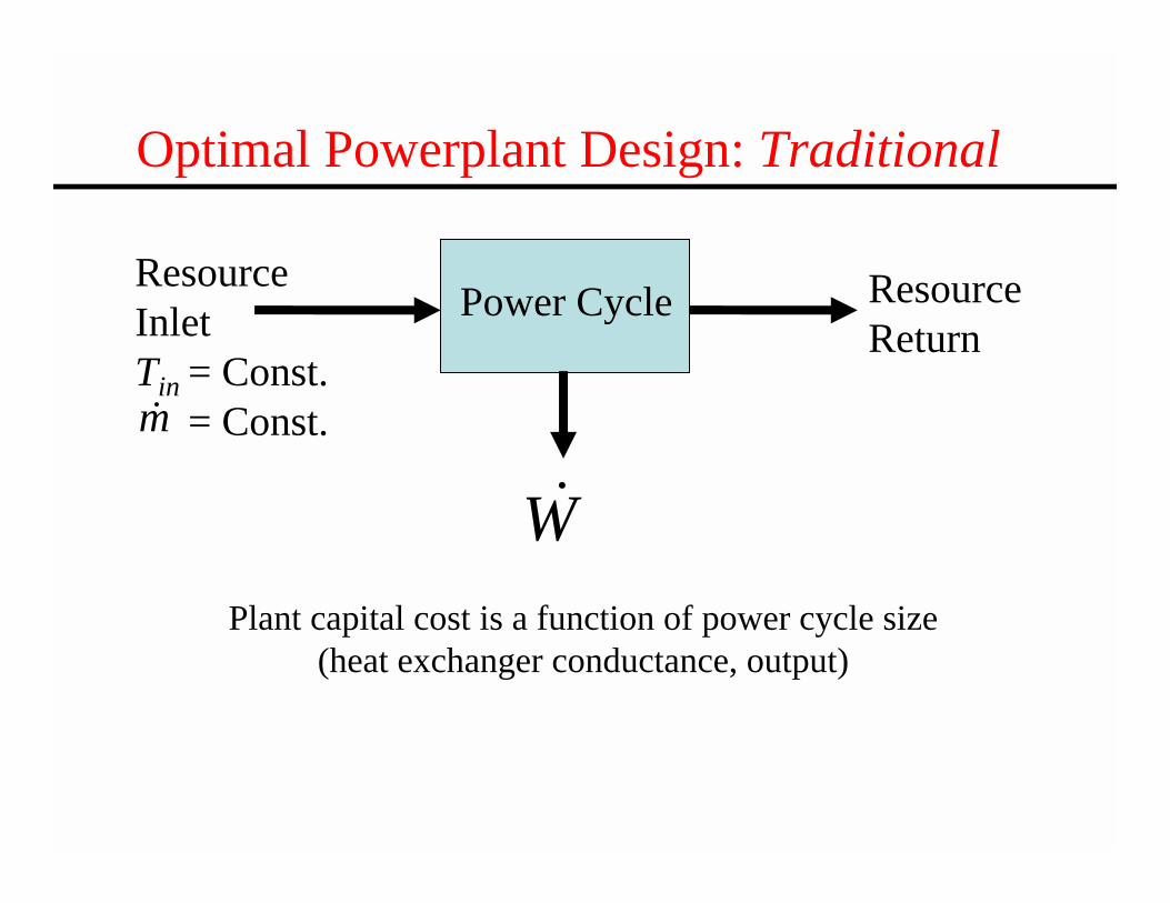
Power CycleResourceInlet Tin = Const.
= Const.
ResourceReturn
Optimal Powerplant Design: Traditional
Plant capital cost is a function of power cycle size (heat exchanger conductance, output)
W&m&
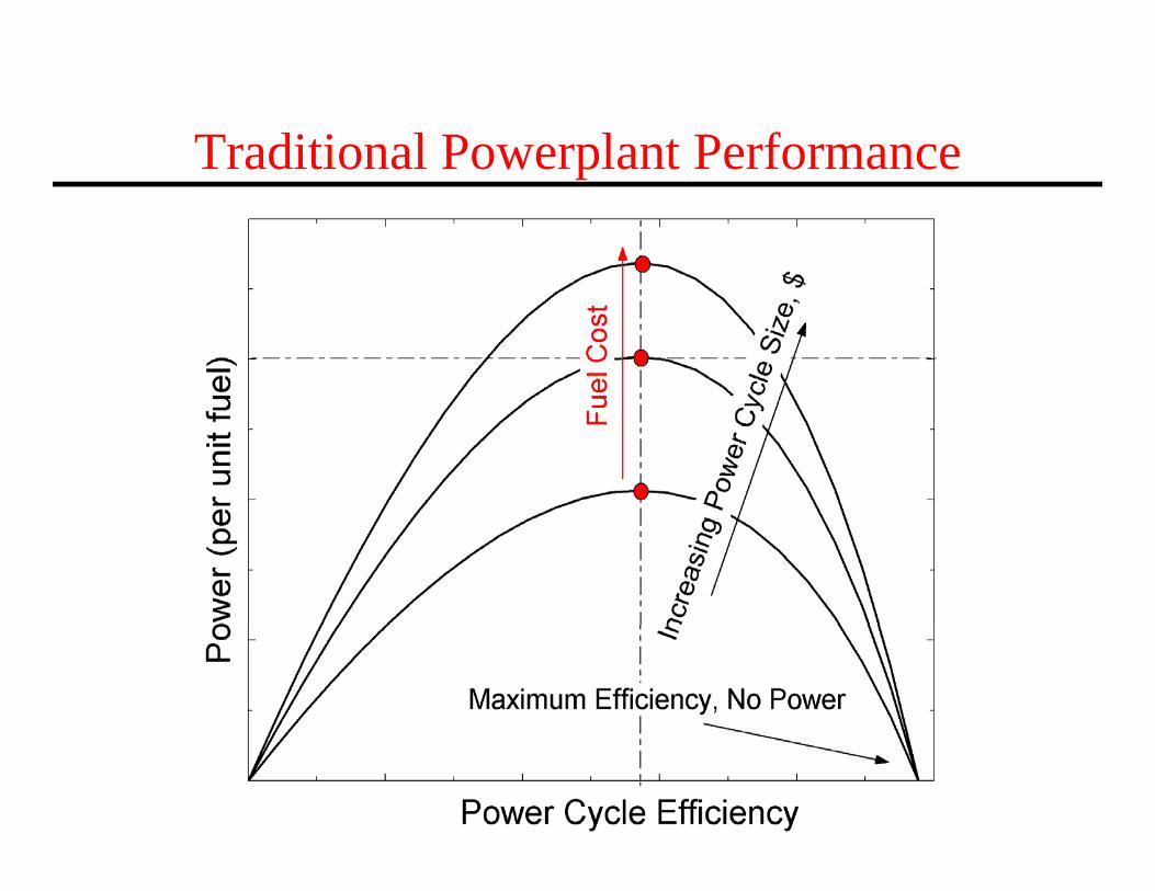
Traditional Powerplant Performance

Power Cycle
Solar Field
Optimal Powerplant Design: Solar
• Solar Field and power cycle performance are coupled• Capital cost is a function of solar field and power cycle size• Solar “fuel” is a capital, rather than recurring, cost
W&
Typical capital cost break-down:• 75% Solar Field
• 25% Power Cycle
Solar Radiation

Solar Powerplant Performance

Solar Powerplant Performance
Power Cycle Cost + Solar Field Cost
Total Plant Cost

Solar Powerplant Performance
Power Cycle Cost + Solar Field Cost
Total Plant Cost

Case Study: Plant Description
• 1 MW Organic Rankine Cycle– n-pentane working fluid– Turbine exhaust recuperation
• Parabolic-trough solar field– Synthetic oil heat transfer fluid

Case Study: Objective Function
$Capital CostIR Investment RatioPlant Output kW
⎡ ⎤= = ⎢ ⎥⎣ ⎦

Case Study: Power Cycle Model

Case Study: Solar Field Model
inT outT
Beam Radiation Losses (Small)

Case Study: Process
Power Cycle Model*
Solar Field Model
Power Cycle Cost Model
$=f(size, output) Solar Field Cost Model
$=f(size)
IR
Boiler PressureHeat Exchanger AreaHeat Exchanger Allocation
*Power Output Fixed

Case Study: Reference Case
100 100ref
IRIR
⋅ =13.1%solar electricη − =
19.8%cycleη =

Case Study: Optimized Case
100 83ref
IRIR
⋅ =16.2%solar electricη − =
25.7%cycleη =

Case Study: Results
• No Change in Power Output
• 5% Increase in total power plant heat exchanger size– 30% Increase in power cycle efficiency
– 24% Increase in solar-to-electric efficiency
– 23% Decrease in solar field area
– 17% Decrease in investment ratio ($/kWNET)

Conclusion
• Optimal design of power cycles for solar-thermal applications favors higher efficiency power cycle operation than traditional powerplants in order to mitigate solar field cost.

QUESTIONS?
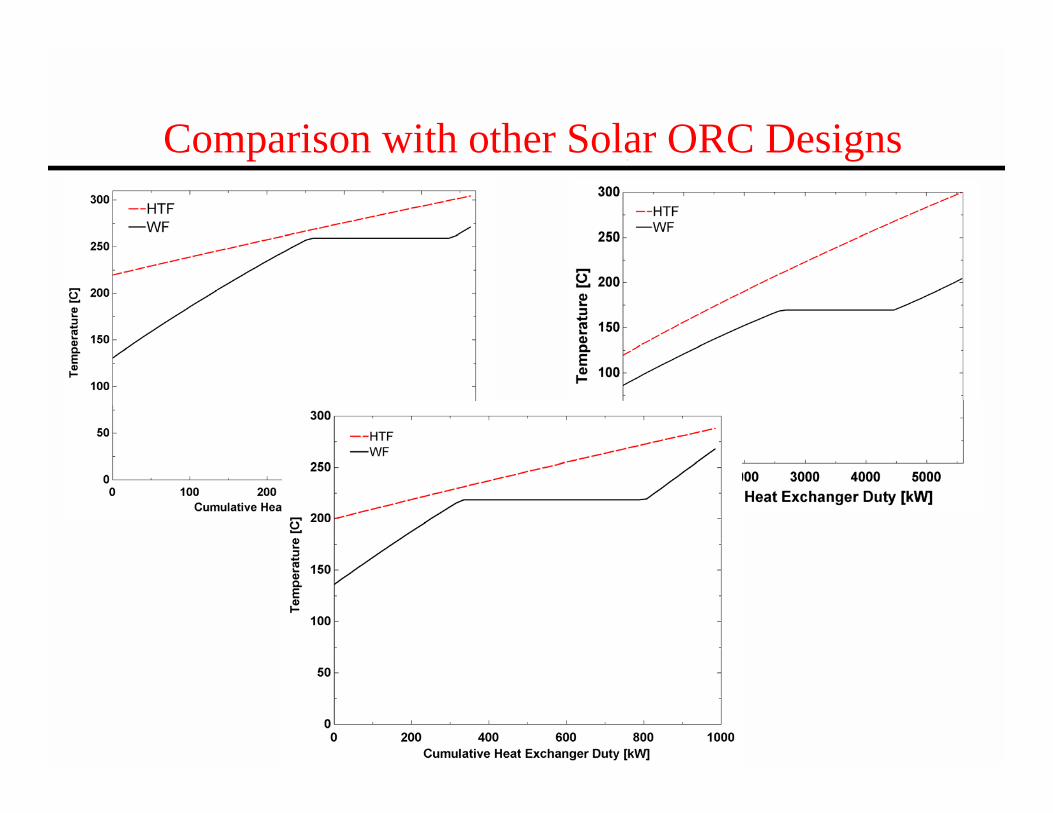
Comparison with other Solar ORC Designs

Cost Model
( )Solar Field Cost f Solar Field Size=
( , )Power Cycle Cost f Power CycleUA Power CycleCapacity=
SF SFSolar Field Cost A C=
0.6
,8 8SF SF PC SF SF
PC REF
Power Cycle CostA C A A C
A=
⎛ ⎞+ ⎜ ⎟⎜ ⎟⎝ ⎠