Design and Optimization of 2-Stage Reduction Gearbox · PDF fileDesign and Optimization of...
12
© 2017 IJEDR | Volume 5, Issue 2 | ISSN: 2321-9939 IJEDR1702095 International Journal of Engineering Development and Research (www.ijedr.org ) 541 Design and Optimization of 2-Stage Reduction Gearbox 1 Neeraj Patel 2 Tarun Gupta 3 Aniket Wankhede 4 Vilas Warudkar 1 2 3 B.Tech Scholar 4 Assistant Professor 1 2 3 4 Department of Mechanical Engineering 1 2 3 4 MANIT Bhopal India ________________________________________________________________________________________________________ Abstract — Engineering design is an iterative process that requires to be dealt with all feasible design solutions in order to arrive at desired objective. Proper design of gearbox has a significant place in power transmission applications. Traditional methods used in its design do not have ability in automating the process. Thus an attempt to automate preliminary design of gearbox has been accomplished in the paper. Software to automate preliminary design of gearbox with spur helical and bevel gears was developed. In the software KISSsoft we apply the problem with the objective function of minimizing of volume of gear trains. The objective function was constrained by bending strength contact stress face width and number of pinion and gear teeth. The preliminary design parameters module number of teeth and width of teeth for pinion and gear pairs of the stages were optimized and gear ratios were determined in respect to the objective function and design constraints. Design optimization of a two stage gearbox by using KISSsoft was accomplished by readily supplying the design parameters requested. Index Terms—Design optimization Gearbox KISSsoft ________________________________________________________________________________________________________ I. I N TRO DUC TION Engineering design is an iterative process that is started with a poorly defined problem refined and then developed a model finally arrived at a solution. Due to nature of engineering design there could be more than one solution therefore a search should be conducted in order to find the best solution. As a mechanical design problem design of gearbox is very complex because of multiple and conflicting objectives. A gearbox utilizes a group of gears to achieve a gear ratio between the driver and driven shafts. The material volume of gear trains is the main determination factor in sizing of this power transmitting units. Trail-and-error method is mainly used in traditional design of gearbox. Researchers have developed several applications using different design and calculation methods. A gearbox producing the required output speed was designed by KISSsoft. An optimal weight design problem of a gear pair system was studied using KISSSOFT. The system was able to find the number of design variables considering specified constraints. A generalized optimal design formulation to gear trains was presented. A computer aided design of gears approach was proposed to optimize one stage gear pair. KISSSOFT was employed for minimizing gear volume by reducing the distance between the centre of gear pairs and other parameters such as transmitting power reduction ratio. The KISSSOFT module was used for optimizing volumes of pitch cylinders of gears for a single reduction gearing system. II. PROJ ECT REQUIREMENTS AND ENGINEERING SPECIFICATIONS We have a desire to switch their drive train reduction from a chain to a gear reduction in order to improve efficiency. We recognized that a gear reduction will increase the weight of the vehicle but we would like the weight to be minimized so that the drive train weight does not increase the weight of the vehicle by more than 10% of the weight of the previous vehicle. We would also like to keep final gear reduction of 10.0:1. In order to meet the packaging requirements of the vehicle the drive train must work with a 0.75 inch input shaft. For optimal integration of the reduction box to each system and the vehicle there is a minimum distance of six inches and maximum distance of eight inches between the centerlines of each shaft. The width of the gear box cannot be greater than five inches. The friction of the drive train must be decreased by 10% when measured by using breakaway torque to rotate as the friction causes a loss of power. To increase the acceleration of vehicle. Also to increase the reliability of the power train. III. MATERIAL SELECTION The first step in the gearbox design process is to select the material. A material is to be selected by doing intensive research on the properties of the various materials. A material is to be selected keeping in mind the various parameters like strength weight
Transcript of Design and Optimization of 2-Stage Reduction Gearbox · PDF fileDesign and Optimization of...

© 2017 IJEDR | Volume 5, Issue 2 | ISSN: 2321-9939
IJEDR1702095 International Journal of Engineering Development and Research (www.ijedr.org) 541
Design and Optimization of 2-Stage Reduction
Gearbox
1Neeraj Patel
2Tarun Gupta
3Aniket Wankhede
4Vilas Warudkar
1 2 3B.Tech Scholar
4Assistant Professor
1 2 3 4 Department of Mechanical Engineering
1 2 3 4 MANIT Bhopal India
________________________________________________________________________________________________________
Abstract— Engineering design is an iterative process that requires to be dealt with all feasible design solutions in order to
arrive at desired objective. Proper design of gearbox has a significant place in power transmission applications.
Traditional methods used in its design do not have ability in automating the process. Thus an attempt to automate
preliminary design of gearbox has been accomplished in the paper. Software to automate preliminary design of gearbox
with spur helical and bevel gears was developed. In the software KISSsoft we apply the problem with the objective
function of minimizing of volume of gear trains. The objective function was constrained by bending strength contact
stress face width and number of pinion and gear teeth. The preliminary design parameters module number of teeth and
width of teeth for pinion and gear pairs of the stages were optimized and gear ratios were determined in respect to the
objective function and design constraints. Design optimization of a two stage gearbox by using KISSsoft was accomplished
by readily supplying the design parameters requested.
Index Terms—Design optimization Gearbox KISSsoft
________________________________________________________________________________________________________
I. INTRO DUCTION
Engineering design is an iterative process that is started with a poorly defined problem refined and then developed a model
finally arrived at a solution. Due to nature of engineering design there could be more than one solution therefore a search should
be conducted in order to find the best solution. As a mechanical design problem design of gearbox is very complex because of
multip le and conflicting objectives.
A gearbox utilizes a group of gears to achieve a gear ratio between the driver and driven shafts. The material volume of gear
trains is the main determination factor in sizing of this power trans mitting units. Trail-and-error method is mainly used in
traditional design of gearbox. Researchers have developed several applications using different design and calculation methods. A
gearbox producing the required output speed was designed by KISSsoft. An optimal weight design problem of a gear pair system
was studied using KISSSOFT. The system was able to find the number of design variab les considering specified constraints. A
generalized optimal design formulation to gear trains was pres ented. A computer aided design of gears approach was proposed
to optimize one stage gear pair. KISSSOFT was employed for min imizing gear volume by reducing the distance between the
centre of gear pairs and other parameters such as transmitting power reduction ratio. The KISSSOFT module was used for
optimizing volumes of pitch cylinders of gears for a single reduction gearing system.
II. PROJECT REQUIREMENTS AND ENGINEERING SPECIFICATIONS
We have a desire to switch their drive train reduction from a chain to a gear reduction in order to improve efficiency. We
recognized that a gear reduction will increase the weight of the vehicle but we would like the weight to be minimized so that the
drive train weight does not increase the weight of the vehicle by more than 10% of the weight of the previous vehicle. We would
also like to keep final gear reduction of 10.0:1. In order to meet the packaging requirements of the vehicle the drive train must
work with a 0.75 inch input shaft.
For optimal integration of the reduction box to each system and the vehicle there is a minimum distance of six inches
and maximum distance of eight inches between the centerlines of each shaft.
The width of the gear box cannot be greater than five inches.
The friction of the drive train must be decreased by 10% when measured by using breakaway torque to rotate as the
friction causes a loss of power.
To increase the acceleration of vehicle.
Also to increase the reliability of the power train.
III. MATERIAL S ELECTION
The first step in the gearbox design process is to select the material. A material is to be selected by doing intensive resea rch on the
properties of the various materials. A material is to be selected keeping in mind the various parameters like strength weight

© 2017 IJEDR | Volume 5, Issue 2 | ISSN: 2321-9939
IJEDR1702095 International Journal of Engineering Development and Research (www.ijedr.org) 542
durability cost and other parameters for the sake of designing gearbox 18CrNiMo case-carburized steel is selected as gear
material due to its better mechanical properties.
TABLE 1 .GEAR MATERIAL SPECIFICATIONS
45C8 carbon steel is selected as shaft material due to its better mechanical properties.
TABLE 2 .SHAFT MATERIAL SPECIFICATIONS
IV. SPUR GEAR DES IGN
Input characteristics:
Power=7.5 KW Rpm=2048
B&G engine- 13.755 ft. lb f@2600 10 hp@3600
Input Torque=25.81 ft. lbf
Gearbox is coupled with CVTech CVT having min imum ratio of 3
and maximum rat io of 0.5.
CVT ratio=3-[𝟐.𝟓(𝒓𝒑𝒎−𝟏𝟖𝟎𝟎)
𝟏𝟖𝟎𝟎]
Rpm = 2600 rcvt=1.88 T=18.65 Nm
Rpm = 2000 rcvt=2.72 T=17.89 Nm
Rpm = 2200 rcvt=2.44
Rpm = 2400 rcvt=2.16
Rpm = 2800 rcvt=1.61
Now for wheel diameter D= 22 inch= 0.558m.
Power=Torque*angular velocity Fig.1 Powertrain Assembly
P=T*ω=7.5*1000=35*ω ω=214.285=2*𝝅*N/60
Hence N=2047.3 rpm.
V= 𝝅∗𝑫∗𝑵
𝟔𝟎=
3 .14∗0.558∗3800∗0.8
60∗10∗0.6=14.81 m/s=53.3 kmph(max.)
Hence to achieve the speed of 53kmph we required the gear reduction of gearbox as 10:1.
IV.I. 1st
Stage Reduction
Following are the input parameters for first stage reduction
Ratio=3.16:1
T=35 Nm P= 7.5 KW N = 2048 rpm for p ressure angle 𝜑 = 20° min. no. of teeth=18.
IV.I.I. Module estimation on the basis of beam strength
𝐦 = [𝟔𝟎∗𝟏𝟎𝟔
𝟑.𝟏𝟒{
𝒌𝒘 ∗𝑪𝒔∗𝒇𝒔
𝒛∗𝑵∗𝑪𝒗 ∗𝒃𝒎
∗𝑺𝒖𝒕𝟑
∗𝒀}]1/3

© 2017 IJEDR | Volume 5, Issue 2 | ISSN: 2321-9939
IJEDR1702095 International Journal of Engineering Development and Research (www.ijedr.org) 543
where Cs=1.5 fs=1.5 Y=0.308 Cv=3
3+𝑣=3/8…assuming velocity = 5m/s.
Substituting values
m=2.66 mm
IV.I.II. Module estimation on the basis of wear strength
m= [𝟔𝟎∗𝟏𝟎𝟔
𝟑.𝟏𝟒{
𝒌𝒘 ∗𝑪𝒔∗𝒇𝒔
𝒛𝟐∗𝒏𝒑∗𝑪𝒗∗𝒃𝒎
∗𝑸∗𝑲}]1/3 Q=
2𝑧𝑔
𝑧𝑔−𝑧𝑝=
2∗57
57−18=2.92 K=0.156{
𝐵𝐻𝑁
100}2
HRC to BHN
HB=5.97*HRC +104.7 HRC=25(for steel)
HB=254 BHN.
Hence module m=3.52 mm
On the basis of above two values the module is selected as 3mm according to the standard value and this value of module have
been verified as per design.
IV.I.III. Check for Design
Pt=𝟐∗𝑴𝒕
𝒅𝒑=2*35000/54=1296.4 V=3.14*dp*np/60*10^3=5.79m/s Cv =3/3+5.79=0.34
Peff .=Cs/Cv*Pt=1.5*648.2*2/0.3412=5697.67 Sb=mb𝜎𝑏Y=3*30*400*0.308=11088N
fs=𝑆𝑏
𝑃𝑒𝑓𝑓 .=1.94 design is satisfied.
So module is selected as 3mm.
IV.I.IV. Minimum number of teeth to avoid interference
For pressure angle= 20° 𝑘 = 1 𝑚 = 3 Np=14.98=15(approx.)
IV.I.V. AGMA /ANSI Procedure
Failure by bending will occur when the significant tooth stress equals or exceeds either the yield strength or the bending
endurance strength. A surface failure occurs when the significant contact stress equals or exceeds the surface endurance stre ngth.
The American Gear Manufacturers Association1 (AGMA) has for many years been the responsible authority for the dissemination
of knowledge pertaining to the design and analysis of gearing. The methods this organization presents are in general use in the
United States when strength and wear are primary considerations. In view of this fact it is important that the AGMA approach to
the subject have been used here.
Diameteral pitch=1/m=25.4/3=8.46teeth/inch V=3.14*dp*np/12 V=1136.1 ft/min.
𝑊=33000*h/V=33000*10/1136.1=290.46 lbf
Face width (f)=1.18 inch.
Two fundamental stress equations are used in the AGMA methodology one for bending stress and another for pitting resistance
(contact stress).
IV.I.V.I. For Bending
1. Velocity factor Kv=1200+V/1200 kv=1.94.
2. Overload factor Ko=1.5
3. Size factor Ks=1
4. Load distribution factor Km= 1.2
5. Rim thickness factor Kb=1
6. Geometry factor J= 0.33
𝜎=wt*ko*kv*ks*pd/f*km*kb/J 𝝈=22036.1126 psi.
𝝈𝒂𝒍𝒍 =St/Sf∗𝒀𝑵
𝑲𝒕∗𝑲𝒓
1. Temp. factor Kt=1
2. Reliab ility factor Kr=1
3. Stress cycle factor Yn =1

© 2017 IJEDR | Volume 5, Issue 2 | ISSN: 2321-9939
IJEDR1702095 International Journal of Engineering Development and Research (www.ijedr.org) 544
St=65000 psi (grade-2) for carburized and hardened steel
Bending factor of safety=65000/22036.1126 using (𝜎𝑎𝑙𝑙
𝜎)
FOSben =2.9 (design is acceptable)
IV.I.V.II. For pitting
1. Elastic coefficient Cp=2300
2. Surface condition factor Cf=1
3. Geometry factor(I)= cos∅t*Sin∅t*ma/2*mn*(ma+1)
ma=gear ratio=3.16 mn=1 hence I=0.12.
𝜎c=Cp*(𝜔𝑡 ∗ 𝐾𝑜 ∗ 𝐾𝑣 ∗ 𝐾𝑠 ∗ 𝐾𝑚 ∗𝐶𝑓
𝐷𝑝∗ 𝐹 ∗ 𝐼)^0.5
σc=133692.96psi
FOSpitting=𝝈𝒄
𝝈𝒂𝒍𝒍=2.039.
Comparing (fos)bending&(fos)2
pitting i.e 1.94 & 4.16
IV.II. 2nd
Stage Reduction
Torque=35*3.16=110.6 Nm Pitch line velocity(V)=3.14*2.12*648.1/12=359.52ft/min.
Wt=33000*H/V=33000*10/359.52=917.88 lbf
Facewidth=37.68/25.4=1.48 inch.
IV.II. I. For bending
1. Velocity factor=1200+V/1200 Kv=1.29
2. Overload factor Ko=1.5
3. Size factor Ks=1
4. Load distribution factor Km=1.2
5. Rim thickness factor Kb=1
6. Geometry factor J=0.33
𝜎=917.88*1.5*1.29*1*8.46*1.2/1.48*0.33
𝝈 =36918psi
FOSben =65000/36918=1.76
IV.II.II. For pitting
1. Elastic coefficient Cp=2300
2. Surface condition factor Cf=1
3. Geometry factor I=0.12
𝝈 = 𝟐𝟑𝟎𝟎 𝟗𝟏𝟕. 𝟖𝟖 ∗ 𝟏. 𝟓 ∗ 𝟏. 𝟐𝟗 ∗ 𝟏 ∗ 𝟏. 𝟐 ∗𝟏
𝟐 .𝟏𝟐∗ 𝟏. 𝟒𝟖 ∗ 𝟎. 𝟏𝟐 0.5
=173046psi
𝜎c all=225000*1.2*1.01/1*1=272700psi
𝐅𝐎𝐒pitting =272700/173046=1.57
Comparing fosb & (fos)2
pitting i.e 1.76 &2.46.
IV.III. Shaft calculations
As shafts are subjected to fluctuating bending and torsional stresses. Hence shafts are designed using DE-Goodman’s criteria of
failure as it is conservative as well as optimum as per design.
IV.III.I. For Intermediate shaft
Wt12=290.46lbf W
t34=917.88lbf
Wcos20= wt12 W
r12=105.72 lbf
Wr34=334.08 lb f d2=6.732inch
T=977.73 lb f.inch (wt12*d3/2)
For X-Y Plane
Wr12+ W
r34=RAY+RBY=105.72+334.08=439.8
Taking moment about point A
RBY*4.2393=wr34*2.9070+w
r12*1.1811
RBY=258.5418lbf

© 2017 IJEDR | Volume 5, Issue 2 | ISSN: 2321-9939
IJEDR1702095 International Journal of Engineering Development and Research (www.ijedr.org) 545
RAY=181.258lbf.
Fig.1 Intermediate shaft (SFD and BMD)
For X-Z Plane
wt12+RAZ+RBZ=W
t34
RAZ+RBZ=627.42
Taking moment about point A
RBZ*4.2393+Wt12*1.1811=W
t34*2.9070
RBZ=548.49 lbf
RAZ=78.9297lbf
Calculating bending moment
For X-Y Plane
Mb=0
Md=Rby*1.3323=344.455 lbf.inch
Me=288.426lbf.in Mc=214.073 lbf.in
Ma=0.
For X-Z Plane
Mb=0
Md=RBZ*1.3323
Md=730.753 lbf.in
Me=456.77 lbf.in
Mc=(RBZ*3.058-Wt34*1.726) Mc=93.02 lbf.in Fig.1 Intermediate shaft (SFD and BMD)
Ma=0.
For shaft material (45 C8 Steel)
Kt=1.7 Kts=1.5 A lloyed steel Sut=95.0 Kpsi.
For Se
1. Surface factor ka=a*(Sut)b a=2.7 b= -0.265. Ka=0.8077.
2. Size factor Kb=0.9
3. Loading factor Kc=1
4. Temp.factor Kd=1
5. Reliab ility factor Ke=0.753
6. Miscellaneous factor Kf=0.5
Se=0.8077*0.9*1*1*0.753*0.5*95=26Kpsi
Using DE-Goodman’s criteria
Ma=540.21 lbf.in Tm=977.73lbf.in
d={𝟏𝟔∗𝟐
𝟑 .𝟏𝟒∗ (𝟐 ∗ 𝑲f*Ma/Se+[3*(Kf s*Tm)
2]0.5
/Sut)}0.33
d=0.7852 inch.
d=0.875 inch (from standard table)
End dia. range=0.726-0.728 inch.
D/d = 1.2 (std.) D= 1.2 *0.875 inch=1.125 inch.
D/d=1.125/0.875=1.2857 which is acceptable.
Assume fillet rad ius r=d/10=0.0875 inch
Kt=1.6 q=0.82 kf=1+q(Kt-1)=1.49
Kts=1.35 qs=0.95.
Kfs=1+qs(Kts-1)=1+0.95(1.35-1)=1.33 Ka=0.8077(no change)
Kb=(d/0.3)-0.107
=0.8917.
Now Se=0.8077*0.8917*1*1*0.753*0.5*95=25.76 Kpsi
𝝈a’=32*Kf*Ma/3.14*d3=12244.61psi
𝝈m’=1.73*16*1.33*977.73/3.14*(0.875)
3’=17131.076 psi
Using Goodman equation
1/nf=𝝈a’/Se+𝝈m
’/Sut=1.54
Check for y ield ing
ny=Sy/𝜎max’>Sy/𝜎a
’+𝜎m
’=82000/12244.61+17131.076=2.8.
IV.III.II. For Input shaft
Wt12=290.46lbf
Wr12=105.72lbf.

© 2017 IJEDR | Volume 5, Issue 2 | ISSN: 2321-9939
IJEDR1702095 International Journal of Engineering Development and Research (www.ijedr.org) 546
T=308.756 lb f.in=309lbf.in
For X-Y Plane
Wr12=RAY+RBY=105.72
Taking moment about point A
RBY*4.2393=Wr12*1.1811
RBY=29.45lbf.
RAY=76.27lbf.
For X-Z Plane
RAZ+RBZ=wt12
Taking moment about point A
RBZ=80.92 lbf.
RAZ=209.79 lbf.
Calculating Bending Moment
For X-Y plane
Mb=0
Mc=76.27*1.1811
Mc=90.08lbf.in
MB=76.27*4.2393-105.72*3.0582=0
For X-Z plane
Mc=RAZ*1.1811=209.79*1.1811=247.78lbf.in
Mr=(Mcxz2+Mcxy
2)0.5
Fig.2 Input shaft (SFD and BMD)
Mr=263.65lbf.in
Se=26Kpsi (from intermediate)
Using DE-Goodman’s criteria
using Mm=Ta=0
Ma=263.65 lbf.in
Tm=309 lb f.in
d=0.5743 inch
d=0.6368 inch.
Kt=1.6 q=0.82 kf=1+q(Kt-1) kf=1.49
kts=1.35 qs=0.95 Kfs=1.33
Ka=0.807 (no change)
Kb=(d/3)-0.107
Kb=0.9226
Now Se=0.8077*0.9226*1*1*0.753*0.5*95=26.65 Kpsi
𝝈a’=15503.337 psi
𝝈m’=14045.56 psi
1/nf=𝝈a’/Se+𝝈m
’/Sut =1.371
IV.III.III. For Output Shaft
For X-Z plane
RAZ+RBZ=Wt34=917.88.
Taking moment about point A
RBZ*4.2393=917.88*2.9070.
RBZ=629.4145 lbf
RAZ=288.465lbf.
For X-Y plane
RAY+RBY=W34t=334.08
Taking moment about point A
RBY*4.2393=Wr34*2.9070
RBY=229.087lbf
RAY=104.9925lbf
Taking X-Y plane
Mc=RAY*2.9070=104.9925*2.9070=305.2132 lb f.inch
Taking X-Z plane
Mc=RAZ*2.9070=288.465*2.9070=838.5677 lbf.inch
Mr= (MCXY2+MCXZ
2)0.5
=892.384lbf.inch
Se=26Kpsi (from intermediate) Fig.3 Output shaft (SFD and BMD)

© 2017 IJEDR | Volume 5, Issue 2 | ISSN: 2321-9939
IJEDR1702095 International Journal of Engineering Development and Research (www.ijedr.org) 547
Mm=Ta=0
Ma=892.384 lbf.inch Tm=3089.6288lbf.inch
d={32/3.14(2*0.5*892.384/26000+{[3*(1.5*3089.6288)2]0.5
}0.33
d=1.0658 inch
d=1.128 inch.
Kt=1.6 q=0.82 Kf=1+q(Kt-1)
Kfs=1.35 qs=0.95 Kfs=1+qs(kfs-1)=1.33.
ka=0.8077
Kb for0.11≤d≤2 inch
Kb=(d/0.3)-0.107
=0.8678
Now Se=0.8077*0.8678*1*1*0.753*0.5*95=25.07 psi.
𝝈a’=32*kf*Ma/3.14*d
3=9441.28psi
𝝈m’=[3*(16*kf s*Tm/3.14*d
3)2]0.5
=25267.87 psi
Using Goodman equation
1/nf=𝝈a’/Se+𝝈m
’/Sut nf=1.556
V. Optimization of parameters
Optimization have been done by using the KISSsoft software.
V.I. For 1st
Stage Reduction
At first power and torque are entered as the basic parameters and other parameters have been optimized in further steps.
Fig.4 User interface of KISSsoft to input parameters
Various iterations have been done through the software of which some of the main iterat ions are listed below, out of which mos t
optimum one have been selected.

© 2017 IJEDR | Volume 5, Issue 2 | ISSN: 2321-9939
IJEDR1702095 International Journal of Engineering Development and Research (www.ijedr.org) 548
Fig.5 List of iterations for 1
st stage reduction
V.II. For 2nd
Stage Reduction
Input parameters
Fig.6 User interface of KISSsoft to input parameters

© 2017 IJEDR | Volume 5, Issue 2 | ISSN: 2321-9939
IJEDR1702095 International Journal of Engineering Development and Research (www.ijedr.org) 549
Fig.7 List of iterations for 2
nd stage reduction
V.III. For Input shaft
The diameter of shaft have been optimized on the basis of strength and deflection.
Fig.8 Optimized input shaft

© 2017 IJEDR | Volume 5, Issue 2 | ISSN: 2321-9939
IJEDR1702095 International Journal of Engineering Development and Research (www.ijedr.org) 550
V.IV. For Intermediate Shaft
Fig.9 Optimized intermediate shaft
V.V. For Output Shaft
Fig.10 Optimized output shaft
VI. RES ULT AND CONCLUS ION
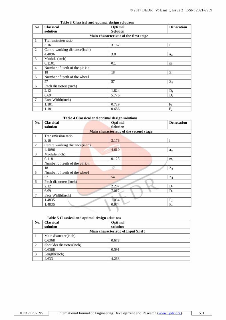
The comparative study of the solutions shown in Table 3 leads to the following conclusions:
− The volume of the all gears and shafts calculated with the classical method is 99.3788 cu.in, while the optimal design
solution offers a smaller volume, equal to 68.069 cu.in. i.e . a 31.503% reduction.
− The optimal design solution has the transmission ratio for the first stage almost equal to the second stage. That confirms
the recommendations found in literature.
© 2017 IJEDR | Volume 5, Issue 2 | ISSN: 2321-9939
IJEDR1702095 International Journal of Engineering Development and Research (www.ijedr.org) 551
Table 3 Classical and optimal design solutions
No. Classical
solution
Optimal
Solution
Denotation
Main characteristic of the first stage
1 Transmission ratio
3.16 3.167 i
2 Centre working distance(inch)
4.4096 3.8 aw
3 Module (inch)
0.1181 0.1 mn
4 Number of teeth of the pin ion
18 18 Z1
5 Number of teeth of the wheel
57 57 Z2
6 Pitch diameters(inch)
2.12 1.824 D1
6.69 5.776 D2
7 Face Width(inch)
1.181 0.729 F1
1.181 0.686 F2
Table 4 Classical and optimal design solutions
No. Classical
solution
Optimal
Solution
Denotation
Main characteristic of the second stage
1 Transmission ratio
3.16 3.176 i
2 Centre working distance(inch)
4.4096 4.610 aw
3 Module(inch)
0.1181 0.125 mn
4 Number of teeth of the pin ion
18 17 Z3
5 Number of teeth of the wheel
57 54 Z4
6 Pitch diameters(inch)
2.12 2.207 D3
6.69 7.012 D4
7 Face Width(inch)
1.4835 1.034 F3
1.4835 0.974 F4
Table 5 Classical and optimal design solutions
No. Classical
solution
Optimal
solution
Main characteristic of Input Shaft
1 Main diameter(inch)
0.6368 0.678
2 Shoulder diameter(inch)
0.6368 0.591
3 Length(inch)
4.633 4.268

© 2017 IJEDR | Volume 5, Issue 2 | ISSN: 2321-9939
IJEDR1702095 International Journal of Engineering Development and Research (www.ijedr.org) 552
Table 6 Classical and optimal design solutions
No. Classical
solution
Optimal
solution
Main characteristic of Intermediate Shaft
1 Main diameter(inch)
0.875 0.875
2 Shoulder diameter(inch)
1.125 0.669
3 Length(inch)
4.633 4.268
Table 7 Classical and optimal design solutions
No. Classical
solution
Optimal
solution
Main characteristic of Output Shaft
1 Main diameter(inch)
1.128 1.100
2 Shoulder diameter(inch)
1.128 1.102
3 Length(inch)
4.633 4.268
VII. REFERENCES
1. Optimal design of two-stage speed reducer, LUCIAN TUDOSE, OVIDIU BUIGA, DANIELA JUCAN, CORNEL
STEFANACHE, ISBN: 978-960-474-019-2, ISSN: 1790-2769, MACMESE'08.
2. Shigley S Mechanical Engineering Design 8th Edition, Pg.349-943.
3. Design of Machine Elements, V.B.Bhandari-2010,Pg 330, 646.
4. KISSsoft Software, Copyright 1998-2015, KISSsoft AG, Rosengartenstrasse 4, CH-8608 Bubikon.
5. Budynas−Nisbett: “Shigley’s Mechanical Engineering Design”, Eighth Edition, 2008; Pg. 746-47
6. Git in M. Maitra:” Handbook of gear design”, 1994
7. Stephen P. Radzevich; “Dudley’s Handbook of Practical Gear Design and Manufacture”, Second Edit ion, 2012
8. Kapelevich, A. and McNamara, T., "Direct Gear Design® for Automotive Applications”, 2013
9. Milosav Ognjanovic1 – Miroslav Milutinovic2,” Design for Reliability Based Methodology For Automotive Gearbox Load
Capacity Identification”, 2012
10. Wikipedia