Design and Manufacturing of Automatic Screw Jack Stepney ...
4
1 Design and Manufacturing of Automatic Screw Jack Stepney for Automobiles Car Suman Kirtaniya #1 , Sumegh Moon #2 , Atul Rajak #3 , Suyog Khadilkar #4 , Suraj Patil #5 Abstract- As the technology is growing so rapidly, the efforts required to do any work is going on decreasing day by day. By implementation of better design the efforts which are required to achieve the desired output can be effectively and economically be decreased. A person an lift heavy load for certain limit of weight, so in this case to lift the overweight screw jack is needed. It becomes more convenient to use when it is motorised. In order to implement this idea, we have designed and developed a system called automatic screw jack stepney. In this system we have used IR (Infrared sensor) and screw jack with small wheel attached to the vehicle axel. Keywords- Battery , DC Motor, Gear Drive ,Lead Screw, Screw Jack. ———————————————————— I. INTRODUCTION When we travel in four-wheeler and if there is puncture in tyre, then problems are face by the user like cannot reach in proper time at the destination and to change the punctured tyre or Stepney. We cannot control and manage the vehicle in puncture situation burst leads to stop the further movement of the car. Our research survey in this regard revealed that in several automobile garages, revealed the facts that mostly some difficult methods were adopted in lifting the vehicles for repair and maintenance. This fabricated model has mainly concentrated on this difficulty. There are mainly two types of jacks- Hydraulic jacks and Mechanical jacks. A Hydraulic jack consists of a cylinder and piston mechanism. The movement of the piston rod is used to raise or lower the load. Mechanical jacks are either hand operated or power driven. The main parts of mechanical screw jack (cylindrical) jack are Body, Screw, Nut and Thrust Bearings. In this type of a jack, the nut remains stationary while the screw rotates and helps in lifting or lowering the load. A screw jack is a portable device consisting of a screw mechanism used to raise or lower the load. The principle on which the screw jack works is similar to that of an inclined plane. Jacks are used frequently in raising cars so that a tire can be changed. A screw jack is commonly used with cars but is also used in many other ways, including industrial machinery and even airplanes. They can be short, tall, fat, or thin depending on the amount of pressure they will be under and the space that they need to fit into. The jack is made out of various types of metal, but the screw itself is generally made out of lead. Some screw jacks are built with anti-backlash. The anti-backlash device moderates the axial backlash in the lifting screw and nut assembly to a regulated minimum. II. PROBLEM DEFINITION Most of the time while travelling problems like leakage of air through tire or puncture of tire occurs. When we are travelling by four-wheeler or more wheeler vehicles and if suddenly the tire gets flat i.e. (puncture), then at that time problems faced by the user like they cannot reach in proper time at their destination & also main problem is it can cause accident. Then at that time we use manual screw jack to lift the car. This process is time consuming and if person don’t know that how to change stepeny then it might be a big problem. III. OBJECTIVES The main objectives of this project are To study the working of motorized screw jack mechanism. Develop the model of the automatic screw jack stepney. Designing of effective mechanism for LMV. IV.MATERIAL and CONSTRUCTION A. Lead Screw The lead screw used as a linkage in a machine to turning motion into linear motion. The size and shape International Journal of Scientific & Engineering Research Volume 11, Issue 7, July-2020 ISSN 2229-5518 22 IJSER © 2020 http://www.ijser.org IJSER
Transcript of Design and Manufacturing of Automatic Screw Jack Stepney ...
1
Design and Manufacturing of Automatic Screw Jack Stepney for Automobiles Car
Suman Kirtaniya#1, Sumegh Moon#2, Atul Rajak#3, Suyog Khadilkar#4, Suraj Patil#5
Abstract- As the technology is growing so rapidly, the efforts required to do any work is going on decreasing day by day. By implementation of better
design the efforts which are required to achieve the desired output can be effectively and economically be decreased. A person an lift heavy load for
certain limit of weight, so in this case to lift the overweight screw jack is needed. It becomes more convenient to use when it is motorised. In order to
implement this idea, we have designed and developed a system called automatic screw jack stepney. In this system we have used IR (Infrared
sensor) and screw jack with small wheel attached to the vehicle axel.
Keywords- Battery , DC Motor, Gear Drive ,Lead Screw, Screw Jack.
————————————————————
I. INTRODUCTION
When we travel in four-wheeler and if there is
puncture in tyre, then problems are face by the user
like cannot reach in proper time at the destination and
to change the punctured tyre or Stepney. We cannot
control and manage the vehicle in puncture situation
burst leads to stop the further movement of the car.
Our research survey in this regard revealed that in
several automobile garages, revealed the facts that
mostly some difficult methods were adopted in lifting
the vehicles for repair and maintenance. This
fabricated model has mainly concentrated on this
difficulty. There are mainly two types of jacks-
Hydraulic jacks and Mechanical jacks. A Hydraulic jack
consists of a cylinder and piston mechanism. The
movement of the piston rod is used to raise or lower
the load. Mechanical jacks are either hand operated or
power driven. The main parts of mechanical screw jack
(cylindrical) jack are Body, Screw, Nut and Thrust
Bearings. In this type of a jack, the nut remains
stationary while the screw rotates and helps in lifting
or lowering the load. A screw jack is a portable device
consisting of a screw mechanism used to raise or lower
the load. The principle on which the screw jack works
is similar to that of an inclined plane. Jacks are used
frequently in raising cars so that a tire can be changed.
A screw jack is commonly used with cars but is also
used in many other ways, including industrial
machinery and even airplanes. They can be short, tall,
fat, or thin depending on the amount of pressure they
will be under and the space that they need to fit into.
The jack is made out of various types of metal, but the
screw itself is generally made out of lead. Some screw
jacks are built with anti-backlash. The anti-backlash
device moderates the axial backlash in the lifting screw
and nut assembly to a regulated minimum.
II. PROBLEM DEFINITION
Most of the time while travelling problems like leakage
of air through tire or puncture of tire occurs. When we
are travelling by four-wheeler or more wheeler
vehicles and if suddenly the tire gets flat i.e.
(puncture), then at that time problems faced by the
user like they cannot reach in proper time at their
destination & also main problem is it can cause
accident. Then at that time we use manual screw jack
to lift the car. This process is time consuming and if
person don’t know that how to change stepeny then it
might be a big problem.
III. OBJECTIVES The main objectives of this project are
To study the working of motorized screw jack
mechanism.
Develop the model of the automatic screw jack
stepney.
Designing of effective mechanism for LMV.
IV.MATERIAL and CONSTRUCTION A. Lead Screw
The lead screw used as a linkage in a machine to
turning motion into linear motion. The size and shape
International Journal of Scientific & Engineering Research Volume 11, Issue 7, July-2020 ISSN 2229-5518
22
IJSER © 2020 http://www.ijser.org
IJSER
23
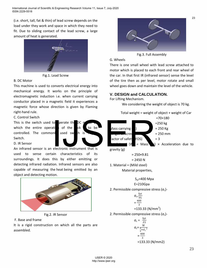
(i.e. short, tall, fat & thin) of lead screw depends on the
load under they work and space in which they need to
fit. Due to sliding contact of the lead screw, a large
amount of heat is generated.
Fig.1. Lead Screw
B. DC Motor
This machine is used to converts electrical energy into
mechanical energy. It works on the principle of
electromagnetic induction i.e. when current carrying
conductor placed in a magnetic field it experiences a
magnetic force whose direction is given by Flaming
right-hand rule.
C. Control Switch
This is the switch used to operate the DC motor by
which the entire operation of the jack is to be
controlled. The commonly used switch is Toggle
Switch.
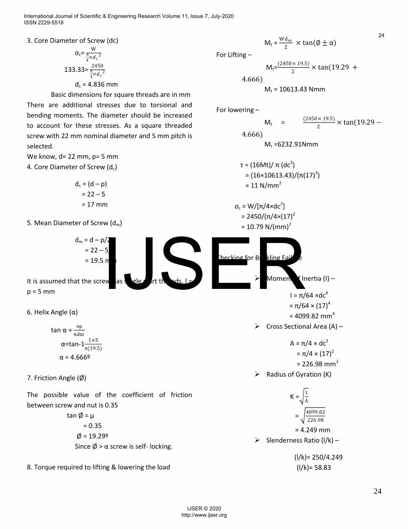
D. IR Sensor
An infrared sensor is an electronic instrument that is
used to sense certain characteristics of its
surroundings. It does this by either emitting or
detecting infrared radiation. Infrared sensors are also
capable of measuring the heat being emitted by an
object and detecting motion.
Fig.2. IR Sensor
F. Base and frame
It is a rigid construction on which all the parts are
assembled.
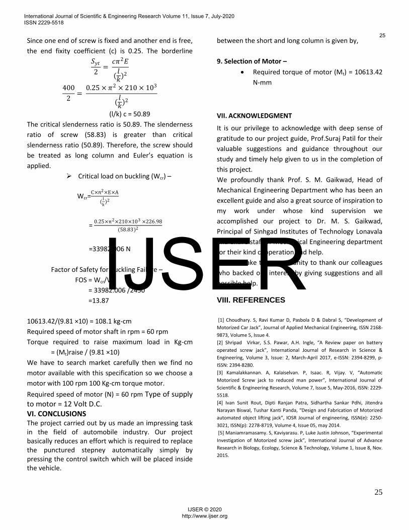
Fig.3. Full Assembly
G. Wheels
There is one small wheel with lead screw attached to
motor which is placed to each front and rear wheel of
the car. In that first IR (infrared sensor) sense the level
of the tire then as per level, motor rotate and small
wheel goes down and maintain the level of the vehicle.
V. DESIGN and CALCULATION. For Lifting Mechanism.
We considering the weight of object is 70 kg.
Total weight = weight of object + weight of Car
=70+180
=250 kg
Mass carrying (m) = 250 Kg
Length of screw = 250 mm
Factor of safety (FOS) = 3
Total Load (W) = Mass (m) × Acceleration due to
gravity (g)
= 250×9.81
= 2450 N
1. Material = (Mild steel)
Material properties,
Syt=400 Mpa
E=210Gpa
2. Permissible compressive stress (σc)-
σc=Syt
FS
= 400
3
=133.33 (N/mm2)
2. Permissible compressive stress (σc)-
σc = Syt
𝐹𝑆
σc= W
π
4×𝑑𝑐
2
= 400
3
=133.33 (N/mm2)
International Journal of Scientific & Engineering Research Volume 11, Issue 7, July-2020 ISSN 2229-5518
23
IJSER © 2020 http://www.ijser.org
IJSER
24
3. Core Diameter of Screw (dc)
σc= W
π
4×𝑑𝑐
2
133.33= 2450
π
4×𝑑𝑐
2
dc = 4.836 mm
Basic dimensions for square threads are in mm
There are additional stresses due to torsional and
bending moments. The diameter should be increased
to account for these stresses. As a square threaded
screw with 22 mm nominal diameter and 5 mm pitch is
selected.
We know, d= 22 mm, p= 5 mm
4. Core Diameter of Screw (dc)
dc = (d – p)
= 22 – 5
= 17 mm
5. Mean Diameter of Screw (dm)
dm = d – p/2
= 22 – 5/2
= 19.5 mm
It is assumed that the screw has single start threads. l =
p = 5 mm
6. Helix Angle (α)
tan α = np
πdm
α=tan-11×5
π(19.5)
α = 4.666º
7. Friction Angle (Ø)
The possible value of the coefficient of friction
between screw and nut is 0.35
tan Ø = μ
= 0.35
Ø = 19.29º
Since Ø > α screw is self- locking.
8. Torque required to lifting & lowering the load
Mt = Wdm
2 × tan(∅± α)
For Lifting –
Mt=(2450× 19.5)
2 × tan(19.29 +
4.666)
Mt = 10613.43 Nmm
For lowering –
Mt = (2450× 19.5)
2 × tan(19.29−
4.666)
Mt =6232.91Nmm
τ = (16Mt)/ π (dc3)
= (16×10613.43)/(π(17)3)
= 11 N/mm2
σc = W/*π/4×dc2]
= 2450/(π/4×(17)2
= 10.79 N/(mm)2
Checking for Buckling Failure
Moment of Inertia (I) –
I = π/64 ×dc4
= π/64 × (17)4
= 4099.82 mm4
Cross Sectional Area (A) –
A = π/4 × dc2
= π/4 × (17)2
= 226.98 mm2
Radius of Gyration (K)
K = I
A
= 4099.82
226.98
= 4.249 mm
Slenderness Ratio (l/k) –
(l/k)= 250/4.249
(l/k)= 58.83
International Journal of Scientific & Engineering Research Volume 11, Issue 7, July-2020 ISSN 2229-5518
24
IJSER © 2020 http://www.ijser.org
IJSER
25
Since one end of screw is fixed and another end is free,
the end fixity coefficient (c) is 0.25. The borderline
between the short and long column is given by,
𝑆𝑦𝑡
2= 𝑐𝜋2𝐸
(𝑙𝑘
)2
400
2=
0.25 × 𝜋2 × 210 × 103
(𝑙𝑘
)2
(l/k) c = 50.89
The critical slenderness ratio is 50.89. The slenderness
ratio of screw (58.83) is greater than critical
slenderness ratio (50.89). Therefore, the screw should
be treated as long column and Euler’s equation is
applied.
Critical load on buckling (Wcr) –
Wcr=C×π2×E×A
(l
k)2
= 0.25×π2×210×103 ×226.98
(58.83)2
=33982.006 N
Factor of Safety for Buckling Failure –
FOS = Wcr/W
= 33982.006 /2450
=13.87
9. Selection of Motor –
Required torque of motor (Mt) = 10613.42
N-mm
VII. ACKNOWLEDGMENT
It is our privilege to acknowledge with deep sense of
gratitude to our project guide, Prof.Suraj Patil for their
valuable suggestions and guidance throughout our
study and timely help given to us in the completion of
this project.
We profoundly thank Prof. S. M. Gaikwad, Head of
Mechanical Engineering Department who has been an
excellent guide and also a great source of inspiration to
my work under whose kind supervision we
accomplished our project to Dr. M. S. Gaikwad,
Principal of Sinhgad Institutes of Technology Lonavala
and entire staff of Mechanical Engineering department
for their kind cooperation and help.
We also take this opportunity to thank our colleagues
who backed our interest by giving suggestions and all
possible help.
VIII. REFERENCES
10613.42/(9.81 ×10) = 108.1 kg-cm
Required speed of motor shaft in rpm = 60 rpm
Torque required to raise maximum load in Kg-cm
= (Mt)raise / (9.81 ×10)
We have to search market carefully then we find no
motor available with this specification so we choose a
motor with 100 rpm 100 Kg-cm torque motor.
Required speed of motor (N) = 60 rpm Type of supply to motor = 12 Volt D.C. VI. CONCLUSIONS The project carried out by us made an impressing task in the field of automobile industry. Our project basically reduces an effort which is required to replace the punctured stepney automatically simply by pressing the control switch which will be placed inside the vehicle.
*1+ Choudhary. S, Ravi Kumar D, Pasbola D & Dabral S, “Development of
Motorized Car Jack”, Journal of Applied Mechanical Engineering, ISSN 2168-
9873, Volume 5, Issue 4.
*2+ Shripad Virkar, S.S. Pawar, A.H. Ingle, “A Review paper on battery
operated screw jack”, International Journal of Research in Science &
Engineering, Volume 3, Issue: 2, March-April 2017, e-ISSN: 2394-8299, p-
ISSN: 2394-8280.
[3] Kamalakkannan. A, Kalaiselvan. P, Isaac. R, Vijay. V, “Automatic
Motorized Screw jack to reduced man power”, International Journal of
Scientific & Engineering Research, Volume 7, Issue 5, May-2016, ISSN: 2229-
5518.
[4] Ivan Sunit Rout, Dipti Ranjan Patra, Sidhartha Sankar Pdhi, Jitendra
Narayan Biswal, Tushar Kanti Panda, “Design and Fabrication of Motorized
automated object lifting jack”, IOSR Journal of engineering, ISSN(e): 2250-
3021, ISSN(p): 2278-8719, Volume 4, Issue 05, may 2014.
[5] Maniamramasamy. S, Kaviyarasu. P, Luke Justin Johnson, “Experimental
Investigation of Motorized screw jack”, International Journal of Advance
Research in Biology, Ecology, Science & Technology, Volume 1, Issue 8, Nov.
2015.
International Journal of Scientific & Engineering Research Volume 11, Issue 7, July-2020 ISSN 2229-5518
25
IJSER © 2020 http://www.ijser.org
IJSER